EP4186805A1 - Production system - Google Patents
Production system Download PDFInfo
- Publication number
- EP4186805A1 EP4186805A1 EP21846161.4A EP21846161A EP4186805A1 EP 4186805 A1 EP4186805 A1 EP 4186805A1 EP 21846161 A EP21846161 A EP 21846161A EP 4186805 A1 EP4186805 A1 EP 4186805A1
- Authority
- EP
- European Patent Office
- Prior art keywords
- information
- containers
- main bodies
- caps
- plastic bottles
- Prior art date
- Legal status (The legal status is an assumption and is not a legal conclusion. Google has not performed a legal analysis and makes no representation as to the accuracy of the status listed.)
- Pending
Links
Images


Classifications
-
- B—PERFORMING OPERATIONS; TRANSPORTING
- B67—OPENING, CLOSING OR CLEANING BOTTLES, JARS OR SIMILAR CONTAINERS; LIQUID HANDLING
- B67B—APPLYING CLOSURE MEMBERS TO BOTTLES JARS, OR SIMILAR CONTAINERS; OPENING CLOSED CONTAINERS
- B67B3/00—Closing bottles, jars or similar containers by applying caps
- B67B3/26—Applications of control, warning, or safety devices in capping machinery
-
- B—PERFORMING OPERATIONS; TRANSPORTING
- B29—WORKING OF PLASTICS; WORKING OF SUBSTANCES IN A PLASTIC STATE IN GENERAL
- B29C—SHAPING OR JOINING OF PLASTICS; SHAPING OF MATERIAL IN A PLASTIC STATE, NOT OTHERWISE PROVIDED FOR; AFTER-TREATMENT OF THE SHAPED PRODUCTS, e.g. REPAIRING
- B29C49/00—Blow-moulding, i.e. blowing a preform or parison to a desired shape within a mould; Apparatus therefor
- B29C49/42—Component parts, details or accessories; Auxiliary operations
- B29C49/4273—Auxiliary operations after the blow-moulding operation not otherwise provided for
-
- B—PERFORMING OPERATIONS; TRANSPORTING
- B65—CONVEYING; PACKING; STORING; HANDLING THIN OR FILAMENTARY MATERIAL
- B65B—MACHINES, APPARATUS OR DEVICES FOR, OR METHODS OF, PACKAGING ARTICLES OR MATERIALS; UNPACKING
- B65B61/00—Auxiliary devices, not otherwise provided for, for operating on sheets, blanks, webs, binding material, containers or packages
- B65B61/26—Auxiliary devices, not otherwise provided for, for operating on sheets, blanks, webs, binding material, containers or packages for marking or coding completed packages
-
- B—PERFORMING OPERATIONS; TRANSPORTING
- B67—OPENING, CLOSING OR CLEANING BOTTLES, JARS OR SIMILAR CONTAINERS; LIQUID HANDLING
- B67B—APPLYING CLOSURE MEMBERS TO BOTTLES JARS, OR SIMILAR CONTAINERS; OPENING CLOSED CONTAINERS
- B67B3/00—Closing bottles, jars or similar containers by applying caps
- B67B3/006—Applying date marks, code marks, or the like, to caps during capping
-
- B—PERFORMING OPERATIONS; TRANSPORTING
- B67—OPENING, CLOSING OR CLEANING BOTTLES, JARS OR SIMILAR CONTAINERS; LIQUID HANDLING
- B67B—APPLYING CLOSURE MEMBERS TO BOTTLES JARS, OR SIMILAR CONTAINERS; OPENING CLOSED CONTAINERS
- B67B3/00—Closing bottles, jars or similar containers by applying caps
- B67B3/20—Closing bottles, jars or similar containers by applying caps by applying and rotating preformed threaded caps
- B67B3/204—Linear-type capping machines
-
- B—PERFORMING OPERATIONS; TRANSPORTING
- B67—OPENING, CLOSING OR CLEANING BOTTLES, JARS OR SIMILAR CONTAINERS; LIQUID HANDLING
- B67C—CLEANING, FILLING WITH LIQUIDS OR SEMILIQUIDS, OR EMPTYING, OF BOTTLES, JARS, CANS, CASKS, BARRELS, OR SIMILAR CONTAINERS, NOT OTHERWISE PROVIDED FOR; FUNNELS
- B67C3/00—Bottling liquids or semiliquids; Filling jars or cans with liquids or semiliquids using bottling or like apparatus; Filling casks or barrels with liquids or semiliquids
- B67C3/007—Applications of control, warning or safety devices in filling machinery
-
- B—PERFORMING OPERATIONS; TRANSPORTING
- B67—OPENING, CLOSING OR CLEANING BOTTLES, JARS OR SIMILAR CONTAINERS; LIQUID HANDLING
- B67C—CLEANING, FILLING WITH LIQUIDS OR SEMILIQUIDS, OR EMPTYING, OF BOTTLES, JARS, CANS, CASKS, BARRELS, OR SIMILAR CONTAINERS, NOT OTHERWISE PROVIDED FOR; FUNNELS
- B67C7/00—Concurrent cleaning, filling, and closing of bottles; Processes or devices for at least two of these operations
-
- B—PERFORMING OPERATIONS; TRANSPORTING
- B29—WORKING OF PLASTICS; WORKING OF SUBSTANCES IN A PLASTIC STATE IN GENERAL
- B29C—SHAPING OR JOINING OF PLASTICS; SHAPING OF MATERIAL IN A PLASTIC STATE, NOT OTHERWISE PROVIDED FOR; AFTER-TREATMENT OF THE SHAPED PRODUCTS, e.g. REPAIRING
- B29C2795/00—Printing on articles made from plastics or substances in a plastic state
- B29C2795/007—Printing on articles made from plastics or substances in a plastic state after shaping
-
- B—PERFORMING OPERATIONS; TRANSPORTING
- B29—WORKING OF PLASTICS; WORKING OF SUBSTANCES IN A PLASTIC STATE IN GENERAL
- B29C—SHAPING OR JOINING OF PLASTICS; SHAPING OF MATERIAL IN A PLASTIC STATE, NOT OTHERWISE PROVIDED FOR; AFTER-TREATMENT OF THE SHAPED PRODUCTS, e.g. REPAIRING
- B29C2949/00—Indexing scheme relating to blow-moulding
- B29C2949/07—Preforms or parisons characterised by their configuration
- B29C2949/0715—Preforms or parisons characterised by their configuration the preform having one end closed
-
- B—PERFORMING OPERATIONS; TRANSPORTING
- B29—WORKING OF PLASTICS; WORKING OF SUBSTANCES IN A PLASTIC STATE IN GENERAL
- B29C—SHAPING OR JOINING OF PLASTICS; SHAPING OF MATERIAL IN A PLASTIC STATE, NOT OTHERWISE PROVIDED FOR; AFTER-TREATMENT OF THE SHAPED PRODUCTS, e.g. REPAIRING
- B29C49/00—Blow-moulding, i.e. blowing a preform or parison to a desired shape within a mould; Apparatus therefor
- B29C49/08—Biaxial stretching during blow-moulding
- B29C49/10—Biaxial stretching during blow-moulding using mechanical means for prestretching
-
- B—PERFORMING OPERATIONS; TRANSPORTING
- B29—WORKING OF PLASTICS; WORKING OF SUBSTANCES IN A PLASTIC STATE IN GENERAL
- B29C—SHAPING OR JOINING OF PLASTICS; SHAPING OF MATERIAL IN A PLASTIC STATE, NOT OTHERWISE PROVIDED FOR; AFTER-TREATMENT OF THE SHAPED PRODUCTS, e.g. REPAIRING
- B29C49/00—Blow-moulding, i.e. blowing a preform or parison to a desired shape within a mould; Apparatus therefor
- B29C49/42—Component parts, details or accessories; Auxiliary operations
- B29C49/4273—Auxiliary operations after the blow-moulding operation not otherwise provided for
- B29C49/428—Joining
- B29C49/42802—Joining a closure or a sealing foil to the article or pincing the opening
-
- B—PERFORMING OPERATIONS; TRANSPORTING
- B29—WORKING OF PLASTICS; WORKING OF SUBSTANCES IN A PLASTIC STATE IN GENERAL
- B29C—SHAPING OR JOINING OF PLASTICS; SHAPING OF MATERIAL IN A PLASTIC STATE, NOT OTHERWISE PROVIDED FOR; AFTER-TREATMENT OF THE SHAPED PRODUCTS, e.g. REPAIRING
- B29C49/00—Blow-moulding, i.e. blowing a preform or parison to a desired shape within a mould; Apparatus therefor
- B29C49/42—Component parts, details or accessories; Auxiliary operations
- B29C49/4273—Auxiliary operations after the blow-moulding operation not otherwise provided for
- B29C49/42808—Filling the article
- B29C49/4281—Filling the article outside the mould
-
- B—PERFORMING OPERATIONS; TRANSPORTING
- B65—CONVEYING; PACKING; STORING; HANDLING THIN OR FILAMENTARY MATERIAL
- B65B—MACHINES, APPARATUS OR DEVICES FOR, OR METHODS OF, PACKAGING ARTICLES OR MATERIALS; UNPACKING
- B65B2220/00—Specific aspects of the packaging operation
- B65B2220/16—Packaging contents into primary and secondary packaging
-
- B—PERFORMING OPERATIONS; TRANSPORTING
- B67—OPENING, CLOSING OR CLEANING BOTTLES, JARS OR SIMILAR CONTAINERS; LIQUID HANDLING
- B67C—CLEANING, FILLING WITH LIQUIDS OR SEMILIQUIDS, OR EMPTYING, OF BOTTLES, JARS, CANS, CASKS, BARRELS, OR SIMILAR CONTAINERS, NOT OTHERWISE PROVIDED FOR; FUNNELS
- B67C3/00—Bottling liquids or semiliquids; Filling jars or cans with liquids or semiliquids using bottling or like apparatus; Filling casks or barrels with liquids or semiliquids
- B67C3/02—Bottling liquids or semiliquids; Filling jars or cans with liquids or semiliquids using bottling or like apparatus
- B67C3/22—Details
- B67C2003/227—Additional apparatus related to blow-moulding of the containers, e.g. a complete production line forming filled containers from preforms
-
- G—PHYSICS
- G05—CONTROLLING; REGULATING
- G05B—CONTROL OR REGULATING SYSTEMS IN GENERAL; FUNCTIONAL ELEMENTS OF SUCH SYSTEMS; MONITORING OR TESTING ARRANGEMENTS FOR SUCH SYSTEMS OR ELEMENTS
- G05B19/00—Program-control systems
- G05B19/02—Program-control systems electric
- G05B19/418—Total factory control, i.e. centrally controlling a plurality of machines, e.g. direct or distributed numerical control [DNC], flexible manufacturing systems [FMS], integrated manufacturing systems [IMS] or computer integrated manufacturing [CIM]
- G05B19/4183—Total factory control, i.e. centrally controlling a plurality of machines, e.g. direct or distributed numerical control [DNC], flexible manufacturing systems [FMS], integrated manufacturing systems [IMS] or computer integrated manufacturing [CIM] characterised by data acquisition, e.g. workpiece identification
-
- G—PHYSICS
- G05—CONTROLLING; REGULATING
- G05B—CONTROL OR REGULATING SYSTEMS IN GENERAL; FUNCTIONAL ELEMENTS OF SUCH SYSTEMS; MONITORING OR TESTING ARRANGEMENTS FOR SUCH SYSTEMS OR ELEMENTS
- G05B19/00—Program-control systems
- G05B19/02—Program-control systems electric
- G05B19/418—Total factory control, i.e. centrally controlling a plurality of machines, e.g. direct or distributed numerical control [DNC], flexible manufacturing systems [FMS], integrated manufacturing systems [IMS] or computer integrated manufacturing [CIM]
- G05B19/41875—Total factory control, i.e. centrally controlling a plurality of machines, e.g. direct or distributed numerical control [DNC], flexible manufacturing systems [FMS], integrated manufacturing systems [IMS] or computer integrated manufacturing [CIM] characterised by quality surveillance of production
-
- Y—GENERAL TAGGING OF NEW TECHNOLOGICAL DEVELOPMENTS; GENERAL TAGGING OF CROSS-SECTIONAL TECHNOLOGIES SPANNING OVER SEVERAL SECTIONS OF THE IPC; TECHNICAL SUBJECTS COVERED BY FORMER USPC CROSS-REFERENCE ART COLLECTIONS [XRACs] AND DIGESTS
- Y02—TECHNOLOGIES OR APPLICATIONS FOR MITIGATION OR ADAPTATION AGAINST CLIMATE CHANGE
- Y02P—CLIMATE CHANGE MITIGATION TECHNOLOGIES IN THE PRODUCTION OR PROCESSING OF GOODS
- Y02P90/00—Enabling technologies with a potential contribution to greenhouse gas [GHG] emissions mitigation
- Y02P90/02—Total factory control, e.g. smart factories, flexible manufacturing systems [FMS] or integrated manufacturing systems [IMS]
Definitions
- the present application relates to a production system.
- PTL 1 discloses a system for producing cans for holding food.
- the bottom surfaces of the cans are printed with individual identification information for identifying the cans (for example, the manufacturing numbers or specimen number etc.).
- the same bottom surfaces of the cans are printed with product information relating to food contained in the cans (for example, the manufacturing lot numbers, manufacturing plants, dates of manufacture, best consumption dates, etc.) by visible ink.
- the cans are inspected by various inspection apparatuses and the results of inspection of the cans are stored in a server linked with the above identification information printed on the cans by invisible ink.
- Food containers are sometimes comprised of main bodies and caps.
- problems can arise in the containers, for example, due to either the main bodies or the caps, or due to the combination of the main bodies and caps.
- only predetermined surfaces of the containers such as the bottom surfaces are printed with identification information and product information, so when a problem arises, there is a possibility that it would be impossible to identify which of the main bodies and caps the cause of the problem lay or which combination of the main bodies and caps it lay in. For this reason, it may be impossible to quickly identify the cause of the problem.
- the present disclosure has as its object the provision of a production system able to improve traceability.
- the production system comprises a conveyor line for conveying the containers, a capper for attaching the caps to the main bodies of the containers on the conveyor line, a reading apparatus configured so as to read first information attached to top surfaces of caps of the containers for identifying the containers at one or more predetermined points after the capper on the conveyor line, and a memory apparatus configured so as to store linked together the first information of the containers, second information attached to the main bodies of the containers for identifying the main bodies, and times when the containers passed one or more predetermined points.
- the containers have main bodies and caps, the top surfaces of the caps are given first information for identifying the containers as a whole, and the main bodies are given second information for identifying the main bodies in the containers. Therefore, by tracing second information of the main bodies to which the caps having the first information are attached at the capper, it is possible to individually identify the main bodies and caps rather than the containers as a whole. Accordingly, when a problem occurs in a container, it is, for example, possible to identify that the problem occurs at what main bodies or caps, or at what combination of the main body and cap. Furthermore, in the production system of one aspect of the present disclosure, the above first information, second information, and times when the containers passed one or more predetermined points are stored linked together in the storage apparatus.
- the containers having the main bodies and caps are usually conveyed with the top surfaces of the caps facing a fixed direction (for example, upward). Accordingly, by attaching the first information to the top surfaces of the caps, it is possible to easily read the first information.
- the production system may further comprise a first apparatus configured so as to attach the first information to the top surfaces of the caps on the conveyor line. In this case, it is possible to attach the first information to the containers on the conveyor line.
- the first apparatus may attach the first information to the top surfaces of the caps by invisible ink unable to be viewed under visible light.
- the first information is used for tracing when containers passed points on a conveyor line, so the first information, for example, need not be made visible to the consumers etc. Therefore, by attaching the first information to containers by invisible ink, it is possible, for example, to improve the design look of the containers.
- the production system may further comprise a second apparatus configured so as to attach second information to the main bodies on the conveyor line. In this case, it is possible to attach second information to the containers on the conveyor line.
- the production system may further comprise a plurality of inspection apparatuses arranged on the conveyor line. Reading apparatuses may be configured so as to read the first information at a plurality of predetermined points corresponding to the plurality of inspection apparatuses. In this case, it is possible to identify the times at which containers pass the inspection apparatuses. Therefore, it is possible to further improve the traceability of the containers.
- FIG. 1 is a schematic view showing a production system according to an embodiment.
- plastic bottles 1 for holding a beverage are manufactured.
- plastic bottles mean bottles made of plastic such as polyethylene terephthalate (PET), polypropylene (PP), and polyethylene (PE). It should be noted that they are not limited to PET bottles.
- the containers may also be beverage containers other than plastic bottles (for example, metal cans or glass bottles). Further, the containers may be containers for holding food other than beverages (for example, health foods, enriched foods, general foods, etc.).
- food can mean all food and beverages (except drugs, quasi-drugs, and regenerative medical products as prescribed for example in Japan's Act on Securing Quality, Efficacy, and Safety of Drugs, Medical Devices, Etc.).
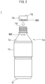
- FIG. 2 is a schematic front view showing one example of a container
- FIG. 3 is a schematic plan view of the container of FIG. 2
- the plastic bottle 1 manufactured by the production system 100 has a main body 1a, cap 1b, and label 1c.
- the main body 1a has a generally hollow cylindrical shape and has a mouth part 1d at the top end part, a barrel part 1e below the mouth part 1d, and a bottom part 1f closing a bottom end part of the barrel part 1e.
- a male screw is formed for screwing with a female screw of the cap 1b.
- the mouth part 1d has an opening for filling a beverage and for drinking it.
- the cap 1b (for example, the top surface 1g of the cap 1b) is given first information M1. Further, referring to FIG. 2 , the main body 1a (for example, the side surface of the barrel part 1e) is given second information M2. Further, the cap 1b (for example, the side surface of the cap 1b) is given third information M3 (the first information M1, second information M2, and third information M3 will be described in detail later).
- the production system 100 for manufacturing the above such plastic bottles 1 comprises a conveyor line L, blow molding machine 2, laser marker (second apparatus) 3, filler 4, capper 5, first printer (first apparatus) 6, bottle inspection machine 7, accumulator 8, temperature regulation apparatus 9, labeler 10, label inspection machine 11, second printer (third apparatus) 12, first cross mark inspection machine 13, caser 14, third printer 15, second print inspection machine 16, palletizer 17, and reading apparatus 18.
- the reading apparatus 18 has a first reader R1, second reader R2, third reader R3, fourth reader R4, and fifth reader R5.
- the production system 100 further comprises a control device 50 configured so as to control all or part of the above component elements.
- the production system 100 may further comprise other component elements.
- the conveyor line L can, for example, be configured so as to convey plastic bottles 1 from the blow molding machine 2 to the palletizer 17.
- the conveyor line L may be configured so as to convey plastic bottles 1 in a single line in the section up to the caser 14 except at specific areas (for example, the accumulator 8 etc.).
- the conveyor line L may also have various conveyor apparatuses.
- the conveyor line L may have a plurality of rotating wheels having grippers for individually holding the main bodies 1a of the plastic bottles 1 (gripper conveyance).
- the conveyor line L may have a plurality of conveyors (for example, belt conveyors).
- the conveyor line L may also have other types of conveyor apparatuses.
- the blow molding machine 2 manufactures the main bodies 1a of the plastic bottles 1 from preforms.
- the blow molding machine 2 may form the main bodies 1a by the stretch blow molding process.
- the preforms are heated then inserted into the molds.
- the preforms are stretched in the height direction by stretch rods and stretched in the width direction by pressurized air.
- the inside surfaces of the preforms are cooled by cold air.
- the main bodies 1a are taken out from the molds.
- the laser marker 3 is configured so as to attach the second information M2 for identifying the main bodies 1a to the main bodies 1a.
- the laser marker 3 is arranged on the conveyor line L in front of the filler 4. Therefore, the second information M2 is attached to the main bodies 1a before the beverage is filled in the main bodies 1a.
- the laser marker 3 may attach the second information M2 to the main bodies 1a at any position of the conveyor line L (for example, any position between the blow molding machine 2 to the accumulator 8 to which the main bodies 1a are conveyed in a certain order).
- the laser marker 3 may be arranged on the conveyor line L downstream from the first printer 6.
- the laser marker 3 is configured so as to print the second information M2 on the side surfaces of the barrel parts 1e of the main bodies 1a. Therefore, the second information M2 can be viewed under visible light.
- the second information M2 can include any symbols enabling differentiation of the main bodies 1a (for example, letters, numbers, shapes, or combinations of these etc.).
- the second information M2 may also, for example, include serial numbers of the manufacturing facilities, manufacturing lot numbers and so on.
- the second information M2 attached to the main bodies 1a by the laser marker 3 can be assigned by the processor 51 of the control device 50 and can be stored in the memory apparatus 52. Further, it should be noted that the second information M2 may also be attached to the main bodies 1a by an apparatus other than the laser marker (for example, an inkjet printer etc.) so long as the second information can be viewed under visible light.
- the filler 4 is configured so as to fill a beverage in the main bodies 1a.
- the filler 4 can have filling ports of one or more beverages. If the filler 4 has a plurality of filling ports, the control device 50 can grasp which filling ports filled the beverages in the main bodies 1a.
- the plastic bottles 1 can be conveyed by the grippers of rotating wheels. The number of grippers of the rotating wheels is known. Further, the rotating wheels can be driven by servo motors controlled by the control device 50. Therefore, the control device 50 can judge by what grippers of what rotating wheels the plastic bottles 1 having specific second information M2 are held and, furthermore, what filling ports the grippers are assigned to.
- the memory apparatus 52 can be configured so as to store linked the second information M2 of the main bodies 1a and the serial numbers of the filling ports filling beverages in the main bodies 1a.
- the beverage contained in the main bodies 1a can be various beverages (for example, water, coffee, tea, cocoa, juice, soup, alcoholic beverages and nonalcoholic beverages and so on).
- the capper 5 is configured so as to close by the caps 1b the mouth parts 1d of the main bodies 1a in which the beverage is filled.
- the filler 4 and the capper 5 are arranged at the inside part of the sterilized chamber C. At the inside part of the chamber C, other component elements (for example, a rinser etc.) may be further arranged.
- the plastic bottles 1 can be conveyed by the conveyors in the above way. While being conveyed by the conveyors, the plastic bottles 1 are placed on the conveyors so that the top surfaces 1g of the caps 1b face upward.
- the first printer 6 is configured so as to attach the first information M1 for identifying the plastic bottles 1 to the plastic bottles 1.
- the first printer 6 is arranged on the conveyor line L behind the capper 5 and in front of the first inspection machine 7 (for example, the exit of the chamber C).
- the first printer 6 may also be configured so as to attach the first information M1 to the plastic bottles 1 held at the final gripper of the final rotating wheel inside of the chamber C or to the plastic bottles 1 right after that.
- the first printer 6 can be an inkjet printer.
- the first information M1 is configured so as to be printed by invisible ink on the top surfaces 1g of the caps 1b.
- the invisible ink can, for example, be ink emitting fluorescent light when irradiated by ultraviolet light. Therefore, the first information M1 cannot be viewed under visible light.
- the first information M1 can include any symbols enabling differentiation of the plastic bottles 1 (for example, letters, numbers, shapes, or combinations of these and so on).
- the first information M1 can be printed as a plurality of dots arranged two-dimensionally. The plurality of dots can, for example, be converted to certain numerical values.
- the first information M1 can be viewed under visible light.
- the first information M1 may be printed on the top surfaces 1g of the caps 1b (for example, by the laser marker).
- the first information M1 can contact the lips of the consumers, so the first information M1 may also be embossed.
- the first information M1 attached to the plastic bottles 1 by the first printer 6 can be assigned by the processor 51 of the control device 50 and can be stored in the memory apparatus 52 linked with the second information M2 attached to the main bodies 1a.
- the control device 50 can judge by what grippers of what rotating wheels the plastic bottles 1 having specific second information M2 are held in the chamber C.
- the first printer 6 can be configured so as to attach the first information M1 to the plastic bottles 1 held by the final gripper in the chamber C or the plastic bottles 1 right after them, so the control device 50 can grasp what second information M2 is attached to the plastic bottles 1 arranged at the first printer 6. Therefore, the control device 50 can link the first information M1 and the second information M2 of the plastic bottles.
- the first reader R1 is arranged corresponding to the bottle inspection machine 7 and is configured so as to read the first information M1 attached to the plastic bottles 1.
- the first reader R1 can be arranged at the conveyor line L so as to detect the times when the plastic bottles 1 pass the bottle inspection machine 7 (for example, right before or right after the bottle inspection machine 7).
- the first reader R1 can include an ultraviolet light emitting apparatus for reading the first information M1 printed by invisible ink.
- the first reader R1 can include any camera configured so as to detect fluorescent light which the invisible ink emits (for example, CCD camera or CMOS camera).
- the first information M1 of the plastic bottles 1 read by the first reader R1 is sent to the control device 50.
- the times when the plastic bottles 1 pass the first reader R1 (that is, substantially the times when the plastic bottles 1 pass the bottle inspection machine 7) are stored in the memory apparatus 52 linked with the first information M1.
- the bottle inspection machine 7 is configured so as to inspect the caps for dirt, scratches, immersion line, etc.
- the inspection results of the plastic bottles 1 at the bottle inspection machine 7 are sent to the control device 50 and stored in the memory apparatus 52 linked with the first information M1 of the plastic bottles 1.
- the accumulator 8 is a buffer area for temporarily holding the plastic bottles 1.
- a single line of a plurality of plastic bottles 1 enters the accumulator 8 and is randomly divided into a plurality of lines inside the accumulator 8. Further, when the plastic bottles 1 exit the accumulator 8, the plurality of lines of plastic bottles 1 are randomly returned to a single line. At this time, the plurality of lines of plastic bottles 1 are not returned to a single line in the same order as when entering. Therefore, the plurality of plastic bottles 1 exit the accumulator 8 in an order different from the time of entry. Further, the accumulator 8 may have a temperature regulation apparatus 9 arranged in it.
- the temperature regulation apparatus 9 can, for example, be a warmer or cooler and is configured so as to discharge cold water, ordinary temperature water, or hot water so as to change the temperature of the beverage in the plastic bottles 1 to ordinary temperature.
- the accumulator 8 may have a sterilization apparatus arranged in it.
- the second reader R2 is arranged corresponding to the labeler 10 and the label inspection machine 11 and is configured so as to read the first information M1 attached to the plastic bottles 1.
- the second reader R2 can be arranged on the conveyor line L so as to detect the times when the plastic bottles 1 passed the labeler 10 and the label inspection machine 11 (for example, right in front of the labeler 10, between the labeler and the label inspection machine 11, or right after the label inspection machine 11).
- the second reader R2 can be configured in the same way as the above first reader R1.
- the first information M1 of the plastic bottles 1 read by the second reader R2 is sent to the control device 50.
- the times when the plastic bottles 1 passed the second reader R2 (that is, substantially the times when the plastic bottles 1 passed the labeler 10 and the label inspection machine 11) are stored in the memory apparatus 52 linked with the first information M1.
- the labeler 10 is configured so as to attach the labels 1c to the main bodies 1a of the plastic bottles 1.
- the labeler 10 can be configured so as to wrap the labels 1c round the main bodies 1a.
- the label inspection machine 11 is configured so as to inspect the labels 1c attached to the main bodies 1a (for example, the positions of the labels 1c etc.). The inspection results of the plastic bottles 1 at the label inspection machine 11 are sent to the control device 50 and are stored in the memory apparatus 52 linked with the first information M1 of the plastic bottles 1.
- the second printer 12 is configured so as to attach the third information M3 to the plastic bottles 1.
- the second printer 12 may be arranged on the conveyor line L after the label inspection machine 11.
- the second printer 12 may also be arranged at another position of the conveyor line L.
- the second printer 12 can be an inkjet printer and can be configured so as to print the third information M3 on the side surfaces of the caps 1b.
- the third information M3 can be viewed under visible light.
- the third information M3, for example, can be information relating to food contained in the containers. For example, it can include at least one of the manufacturing date, best consumption date, and manufacturing lot number.
- the third information M3 attached by the second printer 12 to the plastic bottles 1 can be determined by the processor 51 of the control device 50.
- the third information M3 can be stored in the memory apparatus 52 linked with at least one of the first information M1 and the second information M2.
- the third reader R3 is arranged corresponding to the first print inspection machine 13 and is configured so as to read the first information M1 attached to the plastic bottles 1.
- the third reader R3 can be arranged on the conveyor line L so as to detect the times when the plastic bottles 1 passed the first print inspection machine 13 (for example, right before or right after the first print inspection machine 13).
- the third reader R3 can be similarly configured as the first reader R1 and the second reader R2.
- the first information M1 of the plastic bottles 1 read by the third reader R3 is sent to control device 50.
- the times when the plastic bottles 1 passed the third reader R3 (that is, substantially the times when the plastic bottles 1 passed the first print inspection machine 13) are stored in the memory apparatus 52 linked with the first information M1.
- the first print inspection machine 13 is configured so as to inspect the printing attached to the plastic bottles 1 (for example, the positions of the third information M3 attached to the caps 1b etc.)
- the inspection results of the plastic bottles 1 at the first print inspection machine 13 are sent to the control device 50 and stored in the memory apparatus 52 linked with the first information M1 of the plastic bottles 1.
- the fourth reader R4 is arranged corresponding to the caser 14 and is configured so as to read the first information M1 attached to the plastic bottles 1 entering the caser 14 (for example, right before the caser 14).
- the caser 14 packages pluralities of plastic bottles 1 in cases B (for example, carton boxes etc.)
- a single line of plastic bottles 1 may be divided into a plurality of lines before entering the caser 14.
- the fourth reader R4 may be configured so as to read the first information M1 of the plastic bottles 1 before the single line of plastic bottles 1 is divided into the plurality of lines.
- the fourth reader R4 may be configured so as to read the first information M1 of plastic bottles 1 divided into a plurality of lines.
- the fourth reader R4 can be similarly configured as the first reader R1, the second reader R2, and the third reader R3.
- the first information M1 of the plastic bottles 1 read by the fourth reader R4 is sent to the control device 50. Therefore, the control device 50 can grasp the first information M1 of the pluralities of plastic bottles contained in the cases B.
- the third printer 15 is configured so as to attach to the cases B fourth information for identifying the cases B.
- the third printer 15 can be arranged on the conveyor line L after the caser 14.
- the third printer 15 can be an inkjet printer and the fourth information can be viewed under visible light.
- the fourth information can include any symbols enabling differentiation of the cases B (for example, letters, numbers, shapes, or combinations of these and so forth). Further, the fourth information may include other information (for example, at least one of the first information M1, the second information M2, and the third information M3 of the plastic bottles 1 contained in the cases B).
- the fourth information attached to the cases B by the third printer 15 can be determined by the processor 51 of the control device 50 and is stored in the memory apparatus 52 linked with at least one of the first information M1 and second information M2 of the plastic bottles 1 contained in the cases B.
- the second print inspection machine 16 is configured so as to inspect the printing applied to the cases B (for example, the positions of fourth information attached to the cases B).
- the inspection results of the cases B at the second print inspection machine 16 may be sent to the control device 50 or may be stored in the memory apparatus 52 linked with the fourth information of the cases B.
- the fifth reader R5 is arranged corresponding to the palletizer 17 and is configured so as to read the fourth information attached to the cases B entering the palletizer 17 (for example, right before the palletizer 17).
- the palletizer 17 stacks a plurality of cases B on the pallets.
- a single line of cases B may be divided into a plurality of lines before entering the palletizer 17.
- the fifth reader R5 may be configured so as to read the fourth information of the single line of cases B before the single line of cases B is divided into the plurality of lines.
- the fifth reader R5 may be configured so as to read the fourth information of the cases B divided into the plurality of lines.
- the fifth reader R5 may be any camera configured so as to detect visible ink (for example, a CCD camera or CMOS camera).
- the fourth information of the cases B read by the fifth reader R5 is sent to the control device 50.
- the fourth information of the plurality of cases B stacked on the pallets by the palletizer 17 is stored in the memory apparatus 52.
- the pallets may be given fifth information for identifying the pallets.
- the fifth information can be determined by the processor 51 of the control device 50 and stored in the memory apparatus 52 linked with the fourth information of the cases B contained at the pallets. After that, the pallets can be shipped outside of the production system 100.
- the control device 50 is configured so as to control all or some of the above component elements and can communicate with these component elements by cables or wirelessly.
- the control device 50 can include one or more PLCs (Programmable Logic Controllers) and/or PCs (Personal Computers) etc.
- the control device 50 includes the processor 51, memory apparatus 52, and interface 53.
- the control device 50 may further include other component elements (for example, a display device (for example, a liquid crystal display and/or touch panel etc.) and/or an input device (for example, a mouse, keyboard, touch panel, and/or buttons and so forth)).
- the component elements of the control device 50 can be connected with each other through a bus etc.
- the processor 51 can, for example, include at least one of a CPU, MPU, ASIC, LSI, DSP, or FPGA.
- the processor 51 can be configured so as to perform various processing in accordance with programs stored in the memory apparatus 52.
- the memory apparatus 52 can, for example, include at least one of a hard disk and ROM or RAM.
- the memory apparatus 52 can store programs to be run by the processor 51.
- the processor 51 can be configured so as to store various information in the memory apparatus 52 linked with the first information M1 of the plastic bottles 1, such as
- the plastic bottles 1 have the main bodies 1a and caps 1b.
- the top surfaces 1g of the caps 1b are given first information M1 for identifying the containers 1 as a whole, while the main bodies 1a are given second information M2 for identifying the main bodies 1a in the containers 1. Therefore, by tracing what second information M2 the main bodies 1a, which the caps 1b having the first information M1 are attached to at the capper 5, have, it is possible to also individually identify the main bodies 1a and caps 1b rather than just the containers 1 as a whole.
- the main bodies 1a or caps 1b can be respectively supplied from several suppliers.
- the main bodies 1a and caps 1b can be respectively supplied from several suppliers.
- problems might arise in the containers in only a specific combination. In the production system 100, such a combination can be identified.
- the above first information M1, second information M2, and times at which the plastic bottles 1 pass points at which the readers R1 to R4 are arranged are stored linked together in the memory apparatus 52. Therefore, it is possible to easily trace what point (reader) the many containers 1 having a problem passed at a specific time and possible to quickly identify the cause of the problem. Accordingly, it is possible to improve the traceability. Further, the plastic bottles 1 having the main bodies 1a and caps 1b are usually conveyed so that the top surfaces 1g of the caps 1b face a predetermined direction (for example, upward). Accordingly, by attaching the first information M1 to the top surfaces 1g of the caps 1b, the first information M1 can be easily read.
- the production system 100 further comprises a first printer 6 configured so as to attach the first information M1 to the top surfaces 1g of the caps 1b on the conveyor line L. Therefore, it is possible to attach the first information M1 to the caps 1b on the conveyor line L.
- the first printer 6 attaches the first information M1 to the top surfaces 1g of the caps 1b by invisible ink not able to be viewed under visible light.
- the first information M1 is used for tracing which points on the conveyor line L the plastic bottles 1 passed at what times, so the first information M1 need not, for example, be visible to the consumers etc. Therefore, by attaching the first information M1 on the plastic bottles 1 by invisible ink, for example, the design look of the plastic bottles 1 can be improved.
- the production system 100 further comprises a laser marker 3 configured so as to attach the second information M2 to the main bodies 1a on the conveyor line L. Therefore, it is possible to attach the second information M2 to the main bodies 1a on the conveyor line L.
- the production system 100 comprises a plurality of inspection apparatuses 7, 11, and 13 arranged on the conveyor line L.
- the reading apparatus 18 is configured so as to read the first information M1 at a plurality of predetermined points corresponding to the plurality of inspection apparatuses 7, 11, and 13. Therefore, it is possible to identify the times at which the plastic bottles 1 passed the inspection apparatuses 7, 11, and 13. Therefore, the traceability can be further improved.
- the plurality of plastic bottles 1 exit the accumulator 8 in an order different from when they entered it, so the order of the plastic bottles 1 changes on the conveyor line L.
- the plastic bottles 1 include the first information M1 for identifying the plastic bottles 1. This first information M1 is read by the reading apparatus 18 at predetermined points of the conveyor line. Further, the times when the plastic bottles 1 passed the reading apparatus 18 are stored in the memory apparatus 52 linked with the first information M1 of the plastic bottles 1. Therefore, even if the order of the plastic bottles 1 on the conveyor line L changes, the operator can identify the times at which the plastic bottles 1 passed the points based on the memory apparatus 52. Therefore, the traceability of the plastic bottles 1 can be improved.
- the positions of the third information M3 attached to the caps 1b are inspected at the first print inspection machine 13. If it is judged at the first print inspection machine 13 that the positions of the third information M3 are not in the allowable ranges in the caps 1b, the following causes may be considered.
- the production system 100 is equipped with the first printer 6 on the conveyor line L and first information M1 is attached to the caps 1b on the conveyor line L.
- the first information M1 may also be attached to the caps 1b in advance.
- an additional reader having a configuration similar to the first reader R1 can be arranged at the exit of the chamber C whereby the first information M1 can be linked with other information.
- the production system 100 is equipped with the laser marker 3 on the conveyor line L and the second information M2 is attached to the main bodies 1a on the conveyor line L.
- the second information M2 may also be attached to the main bodies 1a (preforms) in advance. In this case, instead of the laser marker 3, an additional reader able to read the second information M2 can be set at any position whereby the second information M2 can be linked with other information.
- the first information M1 is attached to the plastic bottles 1 by invisible ink.
- the first information M1 may also be attached to the plastic bottles 1 by visible ink.
- the containers having the main bodies and caps plastic bottles 1 are used.
- the containers may also be glass bottles or metal cans having main bodies and caps.
- caps can mean anything able to close the main bodies after food is filled in them and can include caps which cannot be opened by the consumers.
- the main bodies are closed by caps having pull tabs after being filled with food.
- Such caps with pull tabs normally cannot be detached from the main bodies by the consumers.
- the "caps" of the present disclosure may also include such caps.
Landscapes
- Engineering & Computer Science (AREA)
- Mechanical Engineering (AREA)
- Manufacturing & Machinery (AREA)
- General Factory Administration (AREA)
- Details Of Rigid Or Semi-Rigid Containers (AREA)
- Auxiliary Devices For And Details Of Packaging Control (AREA)
- Labeling Devices (AREA)
Abstract
Description
- The present application relates to a production system.
- Known in the past has been a production system for containers for food. For example,
PTL 1 discloses a system for producing cans for holding food. In this system, the bottom surfaces of the cans are printed with individual identification information for identifying the cans (for example, the manufacturing numbers or specimen number etc.). Further, in this system, the same bottom surfaces of the cans are printed with product information relating to food contained in the cans (for example, the manufacturing lot numbers, manufacturing plants, dates of manufacture, best consumption dates, etc.) by visible ink. The cans are inspected by various inspection apparatuses and the results of inspection of the cans are stored in a server linked with the above identification information printed on the cans by invisible ink. - [PTL 1]
Japanese Unexamined Patent Publication No. 2012-79020 - Food containers are sometimes comprised of main bodies and caps. In a production system handling such containers, problems can arise in the containers, for example, due to either the main bodies or the caps, or due to the combination of the main bodies and caps. However, in the system of
PTL 1, only predetermined surfaces of the containers such as the bottom surfaces are printed with identification information and product information, so when a problem arises, there is a possibility that it would be impossible to identify which of the main bodies and caps the cause of the problem lay or which combination of the main bodies and caps it lay in. For this reason, it may be impossible to quickly identify the cause of the problem. - In consideration of the above-such problem, the present disclosure has as its object the provision of a production system able to improve traceability.
- One aspect of the present disclosure is a production system of food containers. In the production system the containers have hollow main bodies having openings at their top parts and caps for closing the openings. The production system comprises a conveyor line for conveying the containers, a capper for attaching the caps to the main bodies of the containers on the conveyor line, a reading apparatus configured so as to read first information attached to top surfaces of caps of the containers for identifying the containers at one or more predetermined points after the capper on the conveyor line, and a memory apparatus configured so as to store linked together the first information of the containers, second information attached to the main bodies of the containers for identifying the main bodies, and times when the containers passed one or more predetermined points.
- In the production system of one aspect of the present disclosure, the containers have main bodies and caps, the top surfaces of the caps are given first information for identifying the containers as a whole, and the main bodies are given second information for identifying the main bodies in the containers. Therefore, by tracing second information of the main bodies to which the caps having the first information are attached at the capper, it is possible to individually identify the main bodies and caps rather than the containers as a whole. Accordingly, when a problem occurs in a container, it is, for example, possible to identify that the problem occurs at what main bodies or caps, or at what combination of the main body and cap. Furthermore, in the production system of one aspect of the present disclosure, the above first information, second information, and times when the containers passed one or more predetermined points are stored linked together in the storage apparatus. Therefore, it is possible to easily trace which points a large number of containers having problems passed at a specific time and possible to quickly identity the cause of the problem. Accordingly, the traceability can be improved. Further, the containers having the main bodies and caps are usually conveyed with the top surfaces of the caps facing a fixed direction (for example, upward). Accordingly, by attaching the first information to the top surfaces of the caps, it is possible to easily read the first information.
- The production system may further comprise a first apparatus configured so as to attach the first information to the top surfaces of the caps on the conveyor line. In this case, it is possible to attach the first information to the containers on the conveyor line.
- The first apparatus may attach the first information to the top surfaces of the caps by invisible ink unable to be viewed under visible light. The first information is used for tracing when containers passed points on a conveyor line, so the first information, for example, need not be made visible to the consumers etc. Therefore, by attaching the first information to containers by invisible ink, it is possible, for example, to improve the design look of the containers.
- The production system may further comprise a second apparatus configured so as to attach second information to the main bodies on the conveyor line. In this case, it is possible to attach second information to the containers on the conveyor line.
- The production system may further comprise a plurality of inspection apparatuses arranged on the conveyor line. Reading apparatuses may be configured so as to read the first information at a plurality of predetermined points corresponding to the plurality of inspection apparatuses. In this case, it is possible to identify the times at which containers pass the inspection apparatuses. Therefore, it is possible to further improve the traceability of the containers.
- According to one aspect of the present disclosure, it is possible to provide a production system for containers able to improve traceability.
-
-
FIG. 1 is a schematic view showing a production system according to an embodiment. -
FIG. 2 is a schematic front view showing one example of a container. -
FIG. 3 is a schematic plan view of the container ofFIG. 2 . - Below, referring to the attached drawings, production systems according to embodiments will be explained. Similar or corresponding elements will be assigned the same reference signs and overlapping explanations will be omitted. To facilitate understanding, sometimes the scale of the figures have been changed.
-
FIG. 1 is a schematic view showing a production system according to an embodiment. In theproduction system 100, as containers for holding food,plastic bottles 1 for holding a beverage are manufactured. Note that, in this Description, "plastic bottles" mean bottles made of plastic such as polyethylene terephthalate (PET), polypropylene (PP), and polyethylene (PE). It should be noted that they are not limited to PET bottles. The containers may also be beverage containers other than plastic bottles (for example, metal cans or glass bottles). Further, the containers may be containers for holding food other than beverages (for example, health foods, enriched foods, general foods, etc.). In this Description, "food" can mean all food and beverages (except drugs, quasi-drugs, and regenerative medical products as prescribed for example in Japan's Act on Securing Quality, Efficacy, and Safety of Drugs, Medical Devices, Etc.). -
FIG. 2 is a schematic front view showing one example of a container, whileFIG. 3 is a schematic plan view of the container ofFIG. 2 . Referring toFIG. 2 , theplastic bottle 1 manufactured by theproduction system 100 has amain body 1a,cap 1b, andlabel 1c. Themain body 1a has a generally hollow cylindrical shape and has amouth part 1d at the top end part, abarrel part 1e below themouth part 1d, and abottom part 1f closing a bottom end part of thebarrel part 1e. Around the outer circumference of themouth part 1d, a male screw is formed for screwing with a female screw of thecap 1b. Themouth part 1d has an opening for filling a beverage and for drinking it. - Referring to
FIG. 3 , thecap 1b (for example, thetop surface 1g of thecap 1b) is given first information M1. Further, referring toFIG. 2 , themain body 1a (for example, the side surface of thebarrel part 1e) is given second information M2. Further, thecap 1b (for example, the side surface of thecap 1b) is given third information M3 (the first information M1, second information M2, and third information M3 will be described in detail later). - Referring to
FIG. 1 , theproduction system 100 for manufacturing the above suchplastic bottles 1 comprises a conveyor line L, blow molding machine 2, laser marker (second apparatus) 3, filler 4,capper 5, first printer (first apparatus) 6,bottle inspection machine 7,accumulator 8,temperature regulation apparatus 9,labeler 10,label inspection machine 11, second printer (third apparatus) 12, first crossmark inspection machine 13,caser 14,third printer 15, secondprint inspection machine 16,palletizer 17, andreading apparatus 18. Thereading apparatus 18 has a first reader R1, second reader R2, third reader R3, fourth reader R4, and fifth reader R5. Further, theproduction system 100 further comprises acontrol device 50 configured so as to control all or part of the above component elements. Theproduction system 100 may further comprise other component elements. - The conveyor line L can, for example, be configured so as to convey
plastic bottles 1 from the blow molding machine 2 to thepalletizer 17. For example, the conveyor line L may be configured so as to conveyplastic bottles 1 in a single line in the section up to thecaser 14 except at specific areas (for example, theaccumulator 8 etc.). The conveyor line L may also have various conveyor apparatuses. For example, in the entire section or partial section from the blow molding machine 2 to the chamber C, the conveyor line L may have a plurality of rotating wheels having grippers for individually holding themain bodies 1a of the plastic bottles 1 (gripper conveyance). Further, for example, in the entire section or partial section from the exit of the chamber C to thepalletizer 17, the conveyor line L may have a plurality of conveyors (for example, belt conveyors). The conveyor line L may also have other types of conveyor apparatuses. - The blow molding machine 2 manufactures the
main bodies 1a of theplastic bottles 1 from preforms. For example, the blow molding machine 2 may form themain bodies 1a by the stretch blow molding process. For example, in the blow molding machine 2, the preforms are heated then inserted into the molds. Next, the preforms are stretched in the height direction by stretch rods and stretched in the width direction by pressurized air. Then, when the preforms swell to the desired shapes, the inside surfaces of the preforms are cooled by cold air. Finally, themain bodies 1a are taken out from the molds. - The
laser marker 3 is configured so as to attach the second information M2 for identifying themain bodies 1a to themain bodies 1a. In the present embodiment, thelaser marker 3 is arranged on the conveyor line L in front of the filler 4. Therefore, the second information M2 is attached to themain bodies 1a before the beverage is filled in themain bodies 1a. For example, in another embodiment, so long as thecontrol device 50 can identify the order of themain bodies 1a, thelaser marker 3 may attach the second information M2 to themain bodies 1a at any position of the conveyor line L (for example, any position between the blow molding machine 2 to theaccumulator 8 to which themain bodies 1a are conveyed in a certain order). For example, thelaser marker 3 may be arranged on the conveyor line L downstream from the first printer 6. Referring toFIG. 2 , for example, thelaser marker 3 is configured so as to print the second information M2 on the side surfaces of thebarrel parts 1e of themain bodies 1a. Therefore, the second information M2 can be viewed under visible light. The second information M2 can include any symbols enabling differentiation of themain bodies 1a (for example, letters, numbers, shapes, or combinations of these etc.). The second information M2 may also, for example, include serial numbers of the manufacturing facilities, manufacturing lot numbers and so on. Referring toFIG. 1 , for example, the second information M2 attached to themain bodies 1a by thelaser marker 3 can be assigned by theprocessor 51 of thecontrol device 50 and can be stored in thememory apparatus 52. Further, it should be noted that the second information M2 may also be attached to themain bodies 1a by an apparatus other than the laser marker (for example, an inkjet printer etc.) so long as the second information can be viewed under visible light. - The filler 4 is configured so as to fill a beverage in the
main bodies 1a. The filler 4 can have filling ports of one or more beverages. If the filler 4 has a plurality of filling ports, thecontrol device 50 can grasp which filling ports filled the beverages in themain bodies 1a. Specifically, for example, as explained above, in the section from the blow molding machine 2 to the inside part of the chamber C, theplastic bottles 1 can be conveyed by the grippers of rotating wheels. The number of grippers of the rotating wheels is known. Further, the rotating wheels can be driven by servo motors controlled by thecontrol device 50. Therefore, thecontrol device 50 can judge by what grippers of what rotating wheels theplastic bottles 1 having specific second information M2 are held and, furthermore, what filling ports the grippers are assigned to. Therefore, thememory apparatus 52 can be configured so as to store linked the second information M2 of themain bodies 1a and the serial numbers of the filling ports filling beverages in themain bodies 1a. The beverage contained in themain bodies 1a can be various beverages (for example, water, coffee, tea, cocoa, juice, soup, alcoholic beverages and nonalcoholic beverages and so on). Thecapper 5 is configured so as to close by thecaps 1b themouth parts 1d of themain bodies 1a in which the beverage is filled. The filler 4 and thecapper 5 are arranged at the inside part of the sterilized chamber C. At the inside part of the chamber C, other component elements (for example, a rinser etc.) may be further arranged. - After the chamber C as well, the
plastic bottles 1 can be conveyed by the conveyors in the above way. While being conveyed by the conveyors, theplastic bottles 1 are placed on the conveyors so that thetop surfaces 1g of thecaps 1b face upward. - The first printer 6 is configured so as to attach the first information M1 for identifying the
plastic bottles 1 to theplastic bottles 1. The first printer 6 is arranged on the conveyor line L behind thecapper 5 and in front of the first inspection machine 7 (for example, the exit of the chamber C). For example, the first printer 6 may also be configured so as to attach the first information M1 to theplastic bottles 1 held at the final gripper of the final rotating wheel inside of the chamber C or to theplastic bottles 1 right after that. For example, the first printer 6 can be an inkjet printer. - Referring to
FIG. 3 , for example, the first information M1 is configured so as to be printed by invisible ink on thetop surfaces 1g of thecaps 1b. The invisible ink can, for example, be ink emitting fluorescent light when irradiated by ultraviolet light. Therefore, the first information M1 cannot be viewed under visible light. The first information M1 can include any symbols enabling differentiation of the plastic bottles 1 (for example, letters, numbers, shapes, or combinations of these and so on). For example, the first information M1 can be printed as a plurality of dots arranged two-dimensionally. The plurality of dots can, for example, be converted to certain numerical values. In another embodiment, the first information M1 can be viewed under visible light. For example, the first information M1 may be printed on thetop surfaces 1g of thecaps 1b (for example, by the laser marker). For example, in the case where the containers are metal cans having pull tabs, the first information M1 can contact the lips of the consumers, so the first information M1 may also be embossed. - Referring to
FIG. 1 , the first information M1 attached to theplastic bottles 1 by the first printer 6 can be assigned by theprocessor 51 of thecontrol device 50 and can be stored in thememory apparatus 52 linked with the second information M2 attached to themain bodies 1a. Specifically, in the above way, thecontrol device 50 can judge by what grippers of what rotating wheels theplastic bottles 1 having specific second information M2 are held in the chamber C. Further, as explained above, the first printer 6 can be configured so as to attach the first information M1 to theplastic bottles 1 held by the final gripper in the chamber C or theplastic bottles 1 right after them, so thecontrol device 50 can grasp what second information M2 is attached to theplastic bottles 1 arranged at the first printer 6. Therefore, thecontrol device 50 can link the first information M1 and the second information M2 of the plastic bottles. - The first reader R1 is arranged corresponding to the
bottle inspection machine 7 and is configured so as to read the first information M1 attached to theplastic bottles 1. The first reader R1 can be arranged at the conveyor line L so as to detect the times when theplastic bottles 1 pass the bottle inspection machine 7 (for example, right before or right after the bottle inspection machine 7). For example, the first reader R1 can include an ultraviolet light emitting apparatus for reading the first information M1 printed by invisible ink. Further, for example, the first reader R1 can include any camera configured so as to detect fluorescent light which the invisible ink emits (for example, CCD camera or CMOS camera). The first information M1 of theplastic bottles 1 read by the first reader R1 is sent to thecontrol device 50. The times when theplastic bottles 1 pass the first reader R1 (that is, substantially the times when theplastic bottles 1 pass the bottle inspection machine 7) are stored in thememory apparatus 52 linked with the first information M1. - The
bottle inspection machine 7 is configured so as to inspect the caps for dirt, scratches, immersion line, etc. The inspection results of theplastic bottles 1 at thebottle inspection machine 7 are sent to thecontrol device 50 and stored in thememory apparatus 52 linked with the first information M1 of theplastic bottles 1. - The
accumulator 8 is a buffer area for temporarily holding theplastic bottles 1. A single line of a plurality ofplastic bottles 1 enters theaccumulator 8 and is randomly divided into a plurality of lines inside theaccumulator 8. Further, when theplastic bottles 1 exit theaccumulator 8, the plurality of lines ofplastic bottles 1 are randomly returned to a single line. At this time, the plurality of lines ofplastic bottles 1 are not returned to a single line in the same order as when entering. Therefore, the plurality ofplastic bottles 1 exit theaccumulator 8 in an order different from the time of entry. Further, theaccumulator 8 may have atemperature regulation apparatus 9 arranged in it. Thetemperature regulation apparatus 9 can, for example, be a warmer or cooler and is configured so as to discharge cold water, ordinary temperature water, or hot water so as to change the temperature of the beverage in theplastic bottles 1 to ordinary temperature. Alternatively or additionally, theaccumulator 8 may have a sterilization apparatus arranged in it. - The second reader R2 is arranged corresponding to the
labeler 10 and thelabel inspection machine 11 and is configured so as to read the first information M1 attached to theplastic bottles 1. The second reader R2 can be arranged on the conveyor line L so as to detect the times when theplastic bottles 1 passed thelabeler 10 and the label inspection machine 11 (for example, right in front of thelabeler 10, between the labeler and thelabel inspection machine 11, or right after the label inspection machine 11). For example, the second reader R2 can be configured in the same way as the above first reader R1. The first information M1 of theplastic bottles 1 read by the second reader R2 is sent to thecontrol device 50. The times when theplastic bottles 1 passed the second reader R2 (that is, substantially the times when theplastic bottles 1 passed thelabeler 10 and the label inspection machine 11) are stored in thememory apparatus 52 linked with the first information M1. - The
labeler 10 is configured so as to attach thelabels 1c to themain bodies 1a of theplastic bottles 1. For example, thelabeler 10 can be configured so as to wrap thelabels 1c round themain bodies 1a. Thelabel inspection machine 11 is configured so as to inspect thelabels 1c attached to themain bodies 1a (for example, the positions of thelabels 1c etc.). The inspection results of theplastic bottles 1 at thelabel inspection machine 11 are sent to thecontrol device 50 and are stored in thememory apparatus 52 linked with the first information M1 of theplastic bottles 1. - The
second printer 12 is configured so as to attach the third information M3 to theplastic bottles 1. For example, thesecond printer 12 may be arranged on the conveyor line L after thelabel inspection machine 11. Thesecond printer 12 may also be arranged at another position of the conveyor line L. Referring toFIG. 2 , for example, thesecond printer 12 can be an inkjet printer and can be configured so as to print the third information M3 on the side surfaces of thecaps 1b. The third information M3 can be viewed under visible light. The third information M3, for example, can be information relating to food contained in the containers. For example, it can include at least one of the manufacturing date, best consumption date, and manufacturing lot number. Referring toFIG. 1 , the third information M3 attached by thesecond printer 12 to theplastic bottles 1 can be determined by theprocessor 51 of thecontrol device 50. The third information M3 can be stored in thememory apparatus 52 linked with at least one of the first information M1 and the second information M2. - The third reader R3 is arranged corresponding to the first
print inspection machine 13 and is configured so as to read the first information M1 attached to theplastic bottles 1. The third reader R3 can be arranged on the conveyor line L so as to detect the times when theplastic bottles 1 passed the first print inspection machine 13 (for example, right before or right after the first print inspection machine 13). For example, the third reader R3 can be similarly configured as the first reader R1 and the second reader R2. The first information M1 of theplastic bottles 1 read by the third reader R3 is sent to controldevice 50. The times when theplastic bottles 1 passed the third reader R3 (that is, substantially the times when theplastic bottles 1 passed the first print inspection machine 13) are stored in thememory apparatus 52 linked with the first information M1. - The first
print inspection machine 13 is configured so as to inspect the printing attached to the plastic bottles 1 (for example, the positions of the third information M3 attached to thecaps 1b etc.) The inspection results of theplastic bottles 1 at the firstprint inspection machine 13 are sent to thecontrol device 50 and stored in thememory apparatus 52 linked with the first information M1 of theplastic bottles 1. - The fourth reader R4 is arranged corresponding to the
caser 14 and is configured so as to read the first information M1 attached to theplastic bottles 1 entering the caser 14 (for example, right before the caser 14). Thecaser 14 packages pluralities ofplastic bottles 1 in cases B (for example, carton boxes etc.) A single line ofplastic bottles 1 may be divided into a plurality of lines before entering thecaser 14. In this case, for example, the fourth reader R4 may be configured so as to read the first information M1 of theplastic bottles 1 before the single line ofplastic bottles 1 is divided into the plurality of lines. Alternatively, for example, the fourth reader R4 may be configured so as to read the first information M1 ofplastic bottles 1 divided into a plurality of lines. For example, the fourth reader R4 can be similarly configured as the first reader R1, the second reader R2, and the third reader R3. The first information M1 of theplastic bottles 1 read by the fourth reader R4 is sent to thecontrol device 50. Therefore, thecontrol device 50 can grasp the first information M1 of the pluralities of plastic bottles contained in the cases B. - The
third printer 15 is configured so as to attach to the cases B fourth information for identifying the cases B. For example, thethird printer 15 can be arranged on the conveyor line L after thecaser 14. For example, thethird printer 15 can be an inkjet printer and the fourth information can be viewed under visible light. The fourth information can include any symbols enabling differentiation of the cases B (for example, letters, numbers, shapes, or combinations of these and so forth). Further, the fourth information may include other information (for example, at least one of the first information M1, the second information M2, and the third information M3 of theplastic bottles 1 contained in the cases B). The fourth information attached to the cases B by thethird printer 15 can be determined by theprocessor 51 of thecontrol device 50 and is stored in thememory apparatus 52 linked with at least one of the first information M1 and second information M2 of theplastic bottles 1 contained in the cases B. - The second
print inspection machine 16 is configured so as to inspect the printing applied to the cases B (for example, the positions of fourth information attached to the cases B). The inspection results of the cases B at the secondprint inspection machine 16 may be sent to thecontrol device 50 or may be stored in thememory apparatus 52 linked with the fourth information of the cases B. - The fifth reader R5 is arranged corresponding to the
palletizer 17 and is configured so as to read the fourth information attached to the cases B entering the palletizer 17 (for example, right before the palletizer 17). Thepalletizer 17 stacks a plurality of cases B on the pallets. A single line of cases B may be divided into a plurality of lines before entering thepalletizer 17. In this case, for example, the fifth reader R5 may be configured so as to read the fourth information of the single line of cases B before the single line of cases B is divided into the plurality of lines. Alternatively, for example, the fifth reader R5 may be configured so as to read the fourth information of the cases B divided into the plurality of lines. For example, the fifth reader R5 may be any camera configured so as to detect visible ink (for example, a CCD camera or CMOS camera). The fourth information of the cases B read by the fifth reader R5 is sent to thecontrol device 50. The fourth information of the plurality of cases B stacked on the pallets by thepalletizer 17 is stored in thememory apparatus 52. The pallets may be given fifth information for identifying the pallets. The fifth information can be determined by theprocessor 51 of thecontrol device 50 and stored in thememory apparatus 52 linked with the fourth information of the cases B contained at the pallets. After that, the pallets can be shipped outside of theproduction system 100. - The
control device 50 is configured so as to control all or some of the above component elements and can communicate with these component elements by cables or wirelessly. For example, thecontrol device 50 can include one or more PLCs (Programmable Logic Controllers) and/or PCs (Personal Computers) etc. For example, thecontrol device 50 includes theprocessor 51,memory apparatus 52, andinterface 53. Thecontrol device 50 may further include other component elements (for example, a display device (for example, a liquid crystal display and/or touch panel etc.) and/or an input device (for example, a mouse, keyboard, touch panel, and/or buttons and so forth)). The component elements of thecontrol device 50 can be connected with each other through a bus etc. - The
processor 51 can, for example, include at least one of a CPU, MPU, ASIC, LSI, DSP, or FPGA. Theprocessor 51 can be configured so as to perform various processing in accordance with programs stored in thememory apparatus 52. Thememory apparatus 52 can, for example, include at least one of a hard disk and ROM or RAM. Thememory apparatus 52 can store programs to be run by theprocessor 51. Further, theprocessor 51 can be configured so as to store various information in thememory apparatus 52 linked with the first information M1 of theplastic bottles 1, such as - ·the second information M2 and the third information M3 of the
plastic bottles 1 and the fourth information of the cases B including theplastic bottles 1 and the fifth information of the pallets - ·the times when the
plastic bottles 1 passed each reader R1, R2, R3, R4, and R5 - ·the inspection results, numerical values, images, and other data at the
inspection machines plastic bottles 1 - ·the pressure of the air at the blow molding machine 2
- ·the ID numbers of the filling ports at the filler 4 and the amounts of the beverage filled
- ·the fastening torque of the
caps 1b at thecapper 5 - ·the wrapping tension at the
labeler 10 - ·the inspection data of selected samples
- In the
production system 100 according to the above such embodiment, theplastic bottles 1 have themain bodies 1a and caps 1b. The top surfaces 1g of thecaps 1b are given first information M1 for identifying thecontainers 1 as a whole, while themain bodies 1a are given second information M2 for identifying themain bodies 1a in thecontainers 1. Therefore, by tracing what second information M2 themain bodies 1a, which thecaps 1b having the first information M1 are attached to at thecapper 5, have, it is possible to also individually identify themain bodies 1a and caps 1b rather than just thecontainers 1 as a whole. Accordingly, when a problem arises incontainers 1, for example, it is possible to identify at which of themain bodies 1a or caps 1b the problem lies, or at which combination of themain bodies 1a and caps 1b the problem lies. For example, themain bodies 1a and caps 1b can be respectively supplied from several suppliers. In this case, for example, there would be a possibility of the existence of several combinations of themain bodies 1a and caps 1b (combinations of suppliers) in the same lot. Problems might arise in the containers in only a specific combination. In theproduction system 100, such a combination can be identified. Furthermore, in theproduction system 100, the above first information M1, second information M2, and times at which theplastic bottles 1 pass points at which the readers R1 to R4 are arranged are stored linked together in thememory apparatus 52. Therefore, it is possible to easily trace what point (reader) themany containers 1 having a problem passed at a specific time and possible to quickly identify the cause of the problem. Accordingly, it is possible to improve the traceability. Further, theplastic bottles 1 having themain bodies 1a and caps 1b are usually conveyed so that thetop surfaces 1g of thecaps 1b face a predetermined direction (for example, upward). Accordingly, by attaching the first information M1 to thetop surfaces 1g of thecaps 1b, the first information M1 can be easily read. - Furthermore, the
production system 100 further comprises a first printer 6 configured so as to attach the first information M1 to thetop surfaces 1g of thecaps 1b on the conveyor line L. Therefore, it is possible to attach the first information M1 to thecaps 1b on the conveyor line L. - Further, in the
production system 100, the first printer 6 attaches the first information M1 to thetop surfaces 1g of thecaps 1b by invisible ink not able to be viewed under visible light. The first information M1 is used for tracing which points on the conveyor line L theplastic bottles 1 passed at what times, so the first information M1 need not, for example, be visible to the consumers etc. Therefore, by attaching the first information M1 on theplastic bottles 1 by invisible ink, for example, the design look of theplastic bottles 1 can be improved. - Further, the
production system 100 further comprises alaser marker 3 configured so as to attach the second information M2 to themain bodies 1a on the conveyor line L. Therefore, it is possible to attach the second information M2 to themain bodies 1a on the conveyor line L. - Further, the
production system 100 comprises a plurality ofinspection apparatuses reading apparatus 18 is configured so as to read the first information M1 at a plurality of predetermined points corresponding to the plurality ofinspection apparatuses plastic bottles 1 passed theinspection apparatuses - Further, in the
production system 100, the plurality ofplastic bottles 1 exit theaccumulator 8 in an order different from when they entered it, so the order of theplastic bottles 1 changes on the conveyor line L. However, theplastic bottles 1 include the first information M1 for identifying theplastic bottles 1. This first information M1 is read by thereading apparatus 18 at predetermined points of the conveyor line. Further, the times when theplastic bottles 1 passed thereading apparatus 18 are stored in thememory apparatus 52 linked with the first information M1 of theplastic bottles 1. Therefore, even if the order of theplastic bottles 1 on the conveyor line L changes, the operator can identify the times at which theplastic bottles 1 passed the points based on thememory apparatus 52. Therefore, the traceability of theplastic bottles 1 can be improved. - For example, in the
production system 100, as explained above, the positions of the third information M3 attached to thecaps 1b are inspected at the firstprint inspection machine 13. If it is judged at the firstprint inspection machine 13 that the positions of the third information M3 are not in the allowable ranges in thecaps 1b, the following causes may be considered. - (1) At the blow molding machine 2, the
main bodies 1a are not formed to the desired heights, the heights of themouth parts 1d and caps 1b end up deviating from the desired heights, and, therefore, at thesecond printer 12, the positions of the third information M3 become off (that is, the blow molding machine 2 has a problem). - (2) At the
labeler 10, thelabels 1c are wrapped around themain bodies 1a with excessive tension, the heights of themouth parts 1d and caps 1b end up deviating from the desired heights, and, therefore, at thesecond printer 12, the positions of the third information M3 become off (that is, thelabeler 10 has a problem). - (3) The settings of the
second printer 12 were poor (that is, thesecond printer 12 has a problem). - If it is learned that several
plastic bottles 1 having third information M3 attached to unsuitable positions have passed a specific apparatus at a similar time, it can be judged that that apparatus has a problem. However, as explained above, the order of theplastic bottles 1 changes on the conveyor line L, so the order of theplastic bottles 1 at the firstprint inspection machine 13 can differ from that at other apparatuses. In theproduction system 100, regarding this point, as explained above, the times when theplastic bottles 1 pass the readers are stored in thememory apparatus 52 linked with the first information M1. Due to this, which apparatuses the severalplastic bottles 1 having third information M3 attached to unsuitable positions passed at a similar time can be easily identified by the operator. Therefore, in theproduction system 100, if for example a defective product is found, it can be possible to easily identify the apparatus having the problem. - An embodiment of a production system of containers was explained, but the present invention is not limited to the above embodiment. A person skilled in the art would understand that various modifications of the above embodiment are possible.
- For example, in the above embodiment, the
production system 100 is equipped with the first printer 6 on the conveyor line L and first information M1 is attached to thecaps 1b on the conveyor line L. However, in another embodiment, the first information M1 may also be attached to thecaps 1b in advance. In this case, instead of the first printer 6, an additional reader having a configuration similar to the first reader R1 can be arranged at the exit of the chamber C whereby the first information M1 can be linked with other information. Further, for example, in the above embodiment, theproduction system 100 is equipped with thelaser marker 3 on the conveyor line L and the second information M2 is attached to themain bodies 1a on the conveyor line L. However, in another embodiment, the second information M2 may also be attached to themain bodies 1a (preforms) in advance. In this case, instead of thelaser marker 3, an additional reader able to read the second information M2 can be set at any position whereby the second information M2 can be linked with other information. - Further, for example, in the above embodiment, the first information M1 is attached to the
plastic bottles 1 by invisible ink. However, in another embodiment, the first information M1 may also be attached to theplastic bottles 1 by visible ink. - Further, for example, in the above embodiment, as the containers having the main bodies and caps,
plastic bottles 1 are used. However, in another embodiment, the containers may also be glass bottles or metal cans having main bodies and caps. Note that, in the present disclosure, "caps" can mean anything able to close the main bodies after food is filled in them and can include caps which cannot be opened by the consumers. For example, in cans having pull tabs, the main bodies are closed by caps having pull tabs after being filled with food. Such caps with pull tabs normally cannot be detached from the main bodies by the consumers. However, the "caps" of the present disclosure may also include such caps. -
- 1
- plastic bottle (container)
- 1a
- main body
- 1b
- cap
- 1g
- top surface of cap
- 3
- laser marker (second apparatus)
- 6
- first printer (first apparatus)
- 7
- bottle inspection machine
- 11
- label inspection machine
- 13
- first cross mark inspection machine
- 18
- reading apparatus
- 52
- memory apparatus
- 100
- production system
- L
- conveyor line
- M1
- first information
- M2
- second information
Claims (5)
- A production system of food containers,in which production system,the containers have hollow main bodies having openings at their top parts and caps for closing the openings, andthe production system comprisesa conveyor line for conveying the containers,a capper for attaching the caps to the main bodies of the containers on the conveyor line,a reading apparatus configured so as to read first information attached to top surfaces of caps of the containers for identifying the containers at one or more predetermined points after the capper on the conveyor line, anda memory apparatus configured so as to store linked together the first information of the containers, second information attached to the main bodies of the containers for identifying the main bodies, and times when the containers passed one or more predetermined points.
- The production system according to claim 1, further comprising a first apparatus configured so as to attach the first information to the top surfaces of the caps on the conveyor line.
- The production system according to claim 2, wherein the first apparatus is configured so as to attach the first information to the top surfaces of the caps by invisible ink unable to be seen under visible light.
- The production system according to any one of claims 1 to 3, further comprising a second apparatus configured so as to attach the second information to the main bodies on the conveyor line.
- The production system according to any one of claims 1 to 4, whereinthe production system further comprises a plurality of inspection apparatuses arranged on the conveyor line, andthe reading apparatuses is configured so as to read the first information at a plurality of predetermined points corresponding to the plurality of inspection apparatuses.
Applications Claiming Priority (2)
| Application Number | Priority Date | Filing Date | Title |
|---|---|---|---|
| JP2020124352A JP7204711B2 (en) | 2020-07-21 | 2020-07-21 | production system |
| PCT/JP2021/027033 WO2022019281A1 (en) | 2020-07-21 | 2021-07-19 | Production system |
Publications (2)
| Publication Number | Publication Date |
|---|---|
| EP4186805A1 true EP4186805A1 (en) | 2023-05-31 |
| EP4186805A4 EP4186805A4 (en) | 2025-01-15 |
Family
ID=79728788
Family Applications (1)
| Application Number | Title | Priority Date | Filing Date |
|---|---|---|---|
| EP21846161.4A Pending EP4186805A4 (en) | 2020-07-21 | 2021-07-19 | PRODUCTION SYSTEM |
Country Status (4)
| Country | Link |
|---|---|
| US (1) | US12084332B2 (en) |
| EP (1) | EP4186805A4 (en) |
| JP (1) | JP7204711B2 (en) |
| WO (1) | WO2022019281A1 (en) |
Families Citing this family (4)
| Publication number | Priority date | Publication date | Assignee | Title |
|---|---|---|---|---|
| JP7823990B2 (en) * | 2022-08-23 | 2026-03-04 | エルジー エナジー ソリューション リミテッド | Cell ID recovery device and its operation method |
| JP2024132667A (en) * | 2023-03-17 | 2024-10-01 | サントリーホールディングス株式会社 | Containment and access restriction methods |
| DE102023133224A1 (en) * | 2023-11-28 | 2025-05-28 | Krones Aktiengesellschaft | METHOD FOR CONTROLLING A PRODUCTION PROCESS IN A PRODUCTION LINE AND PRODUCTION LINE, IN PARTICULAR FILLING LINE |
| DE102023133223A1 (en) * | 2023-11-28 | 2025-05-28 | Krones Aktiengesellschaft | Method and device for tracking containers in a filling plant |
Family Cites Families (13)
| Publication number | Priority date | Publication date | Assignee | Title |
|---|---|---|---|---|
| JP2008035828A (en) * | 2006-08-09 | 2008-02-21 | Takano Foods Kk | Method for producing natto (fermented soybeans) container subjected to laser processing |
| US7765776B1 (en) | 2006-10-19 | 2010-08-03 | Medco Health Solutions, Inc. | Systems and methods for dispensing pharmaceutical/medical product and branding pharmaceutical/medical containers |
| JP4676558B1 (en) | 2010-03-10 | 2011-04-27 | 政行 田口 | Questionnaire system using container lid and container lid |
| JP2012079024A (en) | 2010-09-30 | 2012-04-19 | Hitachi Engineering & Services Co Ltd | Commodity managing system |
| JP4679671B1 (en) | 2010-09-30 | 2011-04-27 | 株式会社日立エンジニアリング・アンド・サービス | production management system |
| JP4759099B1 (en) | 2011-04-12 | 2011-08-31 | 株式会社日立エンジニアリング・アンド・サービス | Production management system and production management method |
| JP4832607B1 (en) | 2011-06-17 | 2011-12-07 | 株式会社日立エンジニアリング・アンド・サービス | Filling equipment |
| JP5835564B2 (en) * | 2011-09-30 | 2015-12-24 | サントリーホールディングス株式会社 | Traceability system for transported goods, linked rotary transport equipment and operation method thereof |
| DE102016203722A1 (en) * | 2016-03-08 | 2017-09-14 | Krones Ag | Device for printing closures of sealed containers |
| FR3062333B1 (en) * | 2017-07-31 | 2021-03-19 | Sidel Participations | PROCESS FOR PRODUCING A SUCCESSION OF CONTAINERS INCLUDING A CONTAINER MARKING STEP |
| JP7340906B2 (en) * | 2017-09-07 | 2023-09-08 | 東洋製罐株式会社 | Container production management system and method |
| JP6914185B2 (en) * | 2017-12-27 | 2021-08-04 | サントリーホールディングス株式会社 | Container inspection device |
| CN208070420U (en) | 2018-03-29 | 2018-11-09 | 新疆乾坤信息技术有限公司 | A kind of blind sample box and quality inspection system |
-
2020
- 2020-07-21 JP JP2020124352A patent/JP7204711B2/en active Active
-
2021
- 2021-07-19 EP EP21846161.4A patent/EP4186805A4/en active Pending
- 2021-07-19 US US18/017,210 patent/US12084332B2/en active Active
- 2021-07-19 WO PCT/JP2021/027033 patent/WO2022019281A1/en not_active Ceased
Also Published As
| Publication number | Publication date |
|---|---|
| JP2022021018A (en) | 2022-02-02 |
| US12084332B2 (en) | 2024-09-10 |
| JP7204711B2 (en) | 2023-01-16 |
| WO2022019281A1 (en) | 2022-01-27 |
| EP4186805A4 (en) | 2025-01-15 |
| US20230294972A1 (en) | 2023-09-21 |
Similar Documents
| Publication | Publication Date | Title |
|---|---|---|
| US12084332B2 (en) | Production system | |
| EP3680739B1 (en) | Container production management system and method | |
| US6834473B2 (en) | Bottling plant and method of operating a bottling plant and a bottling plant with sections for stabilizing the bottled product | |
| US20120085071A1 (en) | Method of treating at least one container in a container treatment plant | |
| US7855648B2 (en) | RFID tag | |
| US8469185B2 (en) | Packaging structure of containers for pharmaceutical use | |
| US20240199401A1 (en) | Container treatment system and container treatment method for treating containers | |
| US8834779B2 (en) | Method and device for assembling a handling unit of filled containers | |
| US20140284380A1 (en) | Readout device for reading out machine-readable markings on receptacles | |
| US20110266293A1 (en) | Deformable Container With Hoop Rings | |
| JP2935263B1 (en) | Rotary body code recognition system and method | |
| US20070163213A1 (en) | Beverage bottling plant for filling beverage bottles with a liquid beverage material and a method of operation thereof | |
| EP3386903B1 (en) | Bottling machine comprising at least two micro-carousels for additive fluids, and related method | |
| AU2017207730A1 (en) | System and method for orienting the rolling direction of an end shell in a metal container manufacturing process | |
| WO2010022385A2 (en) | Container for use in pneumatic transport system | |
| JP5835564B2 (en) | Traceability system for transported goods, linked rotary transport equipment and operation method thereof | |
| WO2015159252A1 (en) | Packaging comprising a case and a product contained therein, both having an identification code, and method for making it | |
| US20230142537A1 (en) | Cartoning machine system and method for cartoning a product | |
| EP2354013B1 (en) | Process for applying a protective device to beverage recipients | |
| JP2019064672A (en) | Commodity control system | |
| CN108268907A (en) | A kind of bad products checkout system and method | |
| Sruthi et al. | Packaging material for coconut beverages | |
| US20240208745A1 (en) | Method and apparatus for inspecting containers filled with liquid | |
| CN106494753A (en) | Compound package material, sheet material group and pack | |
| CN120397394A (en) | Filling equipment, facilities and methods for filling, closing and packaging containers |
Legal Events
| Date | Code | Title | Description |
|---|---|---|---|
| STAA | Information on the status of an ep patent application or granted ep patent |
Free format text: STATUS: THE INTERNATIONAL PUBLICATION HAS BEEN MADE |
|
| PUAI | Public reference made under article 153(3) epc to a published international application that has entered the european phase |
Free format text: ORIGINAL CODE: 0009012 |
|
| STAA | Information on the status of an ep patent application or granted ep patent |
Free format text: STATUS: REQUEST FOR EXAMINATION WAS MADE |
|
| 17P | Request for examination filed |
Effective date: 20230210 |
|
| AK | Designated contracting states |
Kind code of ref document: A1 Designated state(s): AL AT BE BG CH CY CZ DE DK EE ES FI FR GB GR HR HU IE IS IT LI LT LU LV MC MK MT NL NO PL PT RO RS SE SI SK SM TR |
|
| DAV | Request for validation of the european patent (deleted) | ||
| DAX | Request for extension of the european patent (deleted) | ||
| REG | Reference to a national code |
Ref country code: DE Ref legal event code: R079 Free format text: PREVIOUS MAIN CLASS: B65B0043500000 Ipc: G05B0019418000 |
|
| A4 | Supplementary search report drawn up and despatched |
Effective date: 20241212 |
|
| RIC1 | Information provided on ipc code assigned before grant |
Ipc: B65B 61/26 20060101ALI20241206BHEP Ipc: G05B 19/418 20060101AFI20241206BHEP |