EP4186803A2 - Powder intake unit - Google Patents
Powder intake unit Download PDFInfo
- Publication number
- EP4186803A2 EP4186803A2 EP22209776.8A EP22209776A EP4186803A2 EP 4186803 A2 EP4186803 A2 EP 4186803A2 EP 22209776 A EP22209776 A EP 22209776A EP 4186803 A2 EP4186803 A2 EP 4186803A2
- Authority
- EP
- European Patent Office
- Prior art keywords
- powder
- intake unit
- inlet
- powder intake
- ceiling
- Prior art date
- Legal status (The legal status is an assumption and is not a legal conclusion. Google has not performed a legal analysis and makes no representation as to the accuracy of the status listed.)
- Pending
Links
Images


Classifications
-
- B—PERFORMING OPERATIONS; TRANSPORTING
- B65—CONVEYING; PACKING; STORING; HANDLING THIN OR FILAMENTARY MATERIAL
- B65B—MACHINES, APPARATUS OR DEVICES FOR, OR METHODS OF, PACKAGING ARTICLES OR MATERIALS; UNPACKING
- B65B69/00—Unpacking of articles or materials, not otherwise provided for
-
- B—PERFORMING OPERATIONS; TRANSPORTING
- B65—CONVEYING; PACKING; STORING; HANDLING THIN OR FILAMENTARY MATERIAL
- B65B—MACHINES, APPARATUS OR DEVICES FOR, OR METHODS OF, PACKAGING ARTICLES OR MATERIALS; UNPACKING
- B65B37/00—Supplying or feeding fluent-solid, plastic, or liquid material, or loose masses of small articles, to be packaged
- B65B37/02—Supplying or feeding fluent-solid, plastic, or liquid material, or loose masses of small articles, to be packaged by gravity flow
-
- B—PERFORMING OPERATIONS; TRANSPORTING
- B08—CLEANING
- B08B—CLEANING IN GENERAL; PREVENTION OF FOULING IN GENERAL
- B08B9/00—Cleaning hollow articles by methods or apparatus specially adapted thereto
- B08B9/08—Cleaning containers, e.g. tanks
- B08B9/093—Cleaning containers, e.g. tanks by the force of jets or sprays
-
- B—PERFORMING OPERATIONS; TRANSPORTING
- B65—CONVEYING; PACKING; STORING; HANDLING THIN OR FILAMENTARY MATERIAL
- B65B—MACHINES, APPARATUS OR DEVICES FOR, OR METHODS OF, PACKAGING ARTICLES OR MATERIALS; UNPACKING
- B65B69/00—Unpacking of articles or materials, not otherwise provided for
- B65B69/0008—Opening and emptying bags
-
- B—PERFORMING OPERATIONS; TRANSPORTING
- B05—SPRAYING OR ATOMISING IN GENERAL; APPLYING FLUENT MATERIALS TO SURFACES, IN GENERAL
- B05B—SPRAYING APPARATUS; ATOMISING APPARATUS; NOZZLES
- B05B13/00—Machines or plants for applying liquids or other fluent materials to surfaces of objects or other work by spraying, not covered by groups B05B1/00 - B05B11/00
- B05B13/06—Machines or plants for applying liquids or other fluent materials to surfaces of objects or other work by spraying, not covered by groups B05B1/00 - B05B11/00 specially designed for treating the inside of hollow bodies
- B05B13/0627—Arrangements of nozzles or spray heads specially adapted for treating the inside of hollow bodies
-
- B—PERFORMING OPERATIONS; TRANSPORTING
- B65—CONVEYING; PACKING; STORING; HANDLING THIN OR FILAMENTARY MATERIAL
- B65B—MACHINES, APPARATUS OR DEVICES FOR, OR METHODS OF, PACKAGING ARTICLES OR MATERIALS; UNPACKING
- B65B2210/00—Specific aspects of the packaging machine
- B65B2210/06—Sterilising or cleaning machinery or conduits
Definitions
- the invention relates to a powder intake unit and to a method using the powder intake unit for emptying food powder from a bag.
- Various food ingredients are held in bags, such as sugar, milk powder, salt, flour and other forms of food product in powdery or granular form.
- the powder bags are often transported into a hygienic area in which they are opened by an operator and emptied in a powder intake unit, which may also be referred to as a bag tipping unit.
- the powder intake unit has an inlet to receive the powder from the bag and an outlet to discharge the powder for further downstream processing.
- Powder intake units typically have a rectangular shape. Rectangular powder intake units may be deficient in handling powder due to the arrangement of the surfaces in the powder intake unit. For example, powder may adhere to interior surfaces such that some of the powder may not be discharged from the powder intake unit for downstream processing. Conventional powder intake units may also be difficult to clean due to the arrangement of the surfaces. The surfaces may be difficult to clean as the cleaning fluid that is sprayed into the powder intake unit is unable to reach all of the surface area of the surfaces.
- a powder intake unit is configured to receive powder from an opened powder bag.
- the powder intake unit includes an upper section defining an inlet, and a lower conical section that tapers radially inwardly from a top end at which the lower conical section is connected to the upper section to a bottom end at which an outlet for discharging the powder is arranged.
- An upper section of the powder intake unit has a rear wall arranged opposite the inlet and a ceiling that is inclined downwardly from the inlet toward the rear wall.
- the powder intake unit described herein is advantageous in that all of the surfaces are inclined relative to a vertical axis of the powder intake unit, such that the powder moves downwardly along the surfaces toward the outlet during operation.
- the inclined surfaces also facilitate powder removal from the surfaces during cleaning.
- the cleaning spray is able to move downwardly along the surfaces to remove excess powder from the surfaces. The excess powder and cleaning spray are then drawn out of the powder intake unit.
- a method for emptying food powder from a bag includes feeding the powder into the inlet; and discharging the powder from the outlet, such that food powder inside the powder intake unit moves downwardly toward the outlet.
- a powder intake unit 1 configured to receive powder from an opened powder bag.
- the powder bag may contain a food ingredient such as sugar, milk powder, salt, flour or other forms of food product in powdery or granular form.
- the powder intake unit 1 is arranged in a hygienic area along a food processing line.
- the powder intake unit 1 may be configured to receive the powder bag from a conveyor or a machine operator, such that the powder bag is provided to the powder intake unit 1 using an automated process, manual operation, or a combination thereof.
- the powder is emptied from the powder bag into the powder intake unit 1 and subsequently discharged from the powder intake unit 1 for further downstream processing, such as mixing, to produce a food product.
- the powder intake unit 1 is oriented vertically on a ground surface.
- the powder intake unit 1 includes an upper section 2 that defines an inlet 3 configured to receive the powder from the opened powder bag.
- the inlet 3 defines a front of the powder intake unit 1.
- the powder intake unit 1 includes a lower conical section 4 having a top end 5 at which the lower conical section 4 is connected to the upper section 2.
- the lower conical section 4 has a bottom end 6 that is opposite the top end 5 and has an outlet 7 for discharging the powder from the powder intake unit 1.
- the top end 5 and the bottom end 6 may be arranged in horizontal planes.
- the outlet 7 may be circular in shape and defines a vertical axis A which may be a central axis of the powder intake unit 1.
- the lower conical section 4 is tapered radially inwardly from the top end 5 to the bottom end 6 to define a funnel for the powder.
- the entire bottom of the powder intake unit 1 may be defined by the outlet 7.
- the upper section 2 of the powder intake unit 1 has a rear wall 8 that is arranged opposite the inlet 3 that is at the front of the powder intake unit 1.
- a ceiling 9 of the upper section 2 is inclined downwardly from the inlet 3 toward the rear wall 8, such that a top end of the inlet 3 is higher than a top end of the rear wall 8.
- a vacuum outlet 10 is arranged on the ceiling 9 between the rear wall 8 and the inlet 3.
- the vacuum outlet 10 is configured for connection to a vacuum for drawing out the cleaning fluid and powder removed from the surfaces of the powder intake unit 1 during a cleaning operation of the powder intake unit 1.
- the vacuum outlet 10 may be inclined along with the ceiling 9 and is arranged at a location along the ceiling 9 that is proximate the rear wall 8.
- the inlet 3 is opened and closed by a door 11 that is connected to the upper section 2 by arms 12.
- the door 11 is hinged to the ceiling 9 and connected to a rectangular portion 13 of the upper section 2 by the arms 12.
- the rectangular portion 13 defines the inlet 3 and forms a front of the powder intake unit 1 opposite the rear wall 8.
- the arms 12 may be telescoping arms that extend when the door 11 is opened away from the inlet 3 and retract when the door 11 is closed over the inlet 3.
- the door 11 is movable in an upward and downward direction.
- the door 11 has a seal 14 that is arranged along an entirety of the perimeter of the door 11.
- the seal 14 is configured to mate with the inlet 3 for sealing the door 11 and the powder intake unit 1 when the door 11 is closed during operation.
- the inlet 3 and the seal 14 have a complementary shape.
- the door 11 When the door 11 is opened, the door 11 is raised above the powder intake unit 1 such that the inlet 3 is unhindered by the door 11 to enable a maximum open area for receiving the powder inside the powder intake unit 1.
- the door 11 may be held in the open position by the extended arms 12 and a hinge having a mechanical locking mechanism 15 connected between the door 11 and the ceiling 9.
- the inlet 3 and the door 11 may have any suitable shapes.
- the inlet 3 and the door 11 may be rectangular in shape, such that the seal 14 is also rectangular in shape.
- the rectangular portion 13 defines part of the ceiling 9 that is inclined downwardly from the inlet 3 toward the rear wall 8.
- the rectangular portion 13 defines the inlet 3 that is inclined downwardly from the ceiling 9 toward the front of the powder intake unit 1.
- the powder intake unit 1 is supported above the ground by legs 16.
- the legs 16 may be attached to the lower conical section 4 and any number of legs 16 may be provided.
- the powder intake unit 1 may be supported such that the outlet 7 is raised slightly above the ground on which the legs 16 sit.
- the powder intake unit 1 may be supported such that the inlet 3 is positioned at a height that is manually accessible by an operator of the powder intake unit 1.
- a table 17 for the opened powder bag is arranged at the front of the powder intake unit 1 proximate the inlet 3.
- the table 17 is horizontal and removably connectable to the front of the powder intake unit 1.
- the table 17 may include any suitable releasable mechanical connection to the legs 16 arranged at the front of the powder intake unit 1 and the inlet 3.
- the connection may include linkages 18 that directly connect the table 17 to the powder intake unit 1 such that the table 17 is supported above the ground by the connection to the powder intake unit 1.
- a nozzle 19 is mounted to the ceiling 9 and extends downwardly inside the upper section 2.
- the nozzle 19 is configured to spray a cleaning fluid into the powder intake unit 1 for cleaning the inside surfaces of the powder intake unit 1.
- a clamp 20 is provided to clamp the nozzle 19 to the ceiling 9.
- the nozzle 19 includes a spray ball 21 arranged at an axial end of a pipe of the nozzle 19 inside the powder intake unit 1.
- the spray ball 21 may be arranged at a central location of the upper section 2 to ensure that cleaning spray reaches a maximum area of the surfaces during the cleaning operation.
- the pipe of the nozzle 19 has a vertical axis B that is offset from the vertical axis A of the outlet 7.
- the vertical axis B of the nozzle 19 is arranged between the rear wall 8 and the vertical axis A with the vertical axis B being closer to the vertical axis A than the rear wall 8.
- the vertical axis B is offset from the vertical axis A by a distance D that is between 5 and 15 centimeters.
- the distance between the vertical axes A, B may be approximately 10 centimeters.
- the nozzle 19 extends downwardly through a cylindrical portion 22 of the upper section 2 that is connected to the rectangular portion 13.
- the cylindrical portion 22 defines the rear wall 8.
- the bottom of the cylindrical portion 22 is connected to the top end 5 of the lower conical section 4.
- the top end 5 of the lower conical section 4 lies in a horizontal plane, such that the bottom of the cylindrical portion 22 and the top end 5 of the lower conical section 4 meet along the horizontal plane.
- a top portion 23 of the upper section 2 is disc-shaped and extends over the cylindrical portion 22 and the rectangular portion 13 to define the ceiling 9.
- the rectangular portion 13, the cylindrical portion 22, and the top portion 23 may be formed integrally as one piece or as separate pieces that are subsequently attached together.
- ends of the inlet 3 and the ceiling 9 meet at a point 30 that is arranged along the vertical axis A defined by the outlet 7, such that the ceiling 9 is arranged on one side of the vertical axis A and the inlet 3 is arranged on the opposite side of the vertical axis A.
- the rear wall 8 is arranged on the same side of the vertical axis A as the ceiling 9.
- the surface of the lower conical section 4 extends around the vertical axis A.
- the point 30 may form a topmost point of the powder intake unit 1.
- the nozzle 19 is arranged between the rear wall 8 and the topmost point 30.
- the inlet 3 may extend downwardly in a direction toward the front 311 of the powder intake unit 1.
- the inlet 3 may extend downwardly in a direction toward a frontmost end 31, of the powder intake unit 1.
- the front 311 of the powder intake unit 1 may be defined as the side of the powder intake unit 1 where the inlet 3 is arranged. Downwardly may be defined as the direction that is downwards in relation to the vertical direction.
- the inlet 3 may be angled downward toward the front 311 of the powder intake unit 1 relative to the vertical axis A by an angle ⁇ that is smaller than 90 degrees, by an angle ⁇ that is smaller than 80 degrees, or by an angle ⁇ that is even smaller.
- the inlet 3 may be angled toward the front 311 of the powder intake unit 1 relative to the vertical axis A by an angle ⁇ that is between 20 and 60 degrees, or by an angle ⁇ that is between 30 and 60 degrees.
- the angle ⁇ may be approximately 45 degrees.
- the inlet 3 extends downwardly from the topmost point 30 away from the ceiling 9 to the frontmost end 31 of the powder intake unit 1.
- the frontmost end 31 also defines a bottom of the inlet 3.
- the lower conical section 4 meets the inlet 3 at the frontmost end 31.
- the table 17 may be removably connected to the powder intake unit 1 proximate the frontmost end 31 such that the table 17 extends horizontally outwardly from the frontmost end 31.
- all of the surfaces of the powder intake unit 1 are inclined relative to the vertical axes A, B. All of the surfaces being inclined enables the powder to move downwardly along the surfaces toward the outlet 7 during operation by way of gravity. During cleaning, the inclined surfaces enable the cleaning spray to move downwardly along the surfaces and remove excess powder from the surfaces. The removed powder and cleaning spray is then drawn out of the powder intake unit 1 by a vacuum.
- Each of the inlet 3, the ceiling 9, and the surface of the lower conical section 4 is inclined by at least 20 degrees relative to the vertical axes A, B.
- the ceiling 9 is angled downwardly from the topmost point 30 toward the rear wall 8 relative to the vertical axis A by an angle ⁇ .
- the angle ⁇ is less than 90 degrees and greater than the angle ⁇ between the vertical axis A and the inlet 3.
- the angle ⁇ may be approximately 60 degrees.
- the ceiling 9 meets the rear wall 8 of the cylindrical portion 22 along a curved portion 32 of the upper section 2.
- the curved portion 32 is defined by the top portion 23 of the upper section 2 and may form a rearmost portion of the powder intake unit 1.
- the ceiling 9 and the rear wall 8 may be angled relative to each other by an angle ⁇ that is less than 90 degrees.
- the rear wall 8 is angled relative to the vertical axes A, B of the powder intake unit 1 by an angle ⁇ that is greater than an angle ⁇ by which a surface of the lower conical section 4 is angled relative to the vertical axes A, B.
- Each of the angles ⁇ , ⁇ may be between 30 and 60 degrees.
- a length of the rear wall 8 extending from the ceiling 9 to the top end 5 of the lower conical section 4 is less than a length of the surface of the lower conical section 4 from the bottom end 6 to the top end 5.
- the length of the rear wall 8 may be less than the length of the inlet 3 from the topmost point 30 to the frontmost end 31 and the length of the ceiling 9 from the topmost point 30 to the curved portion 32.
- the inlet 3 is defined by parallel inclined sides 33 and parallel horizontal sides 34, 35.
- the parallel horizontal sides 34, 35 define a bottom and top of the inlet 3.
- the topmost point 30 of the powder intake unit 1 is arranged along the top horizontal side 34 and the frontmost end 31 is arranged along the bottom horizontal side 35.
- the parallel inclined sides 33 extend from the bottom horizontal side 35 to the top horizontal side 34 and are inclined relative to the vertical axis B of the nozzle 20.
- the parallel horizontal sides 34, 35 extend between the parallel inclined sides 33 to define a width W of the inlet 3.
- the length of the parallel horizontal sides 34, 35 may be longer than the length of the parallel inclined sides 33.
- Each of the corners at which one of the inclined sides 33 meets one of the parallel horizontal sides 34, 35 defines a radius of curvature R that is less than the width W of the inlet 3.
- the radius of curvature R may be between 5 and 15% of the width W.
- Each radius of curvature R may be the same along the inlet 3.
- the seal 14 and the door 11 has a shape that is complementary to the shape of the inlet 3, such that the door 11 includes similar radii of curvature to the inlet 3. Providing the inlet 3 with radii of curvature enables a maximum opening area for the powder intake unit 1 to facilitate emptying of the powder bag.
- a top view of the powder intake unit 1 is shown.
- the vacuum outlet 10 is formed in a central location of the top portion 23 of the upper section 2.
- the top portion 23 is continuously formed with the rear wall 8 and the rectangular portion 24.
- the clamp 20 for the nozzle is arranged between the rectangular portion 24 and the top portion 23.
- the clamp 20 may be arranged along a horizontal central axis C of the powder intake unit 1 that is defined from a front end to a back end of the powder intake unit 1.
- the door 11 includes a handle 36 formed on an outside surface of the door 11.
- the top portion 23 of the upper section 2, the rectangular section 24, the door 11, and the table 17 may have a symmetrical shape about the central axis C.
- the upper section 2 does not have a symmetrical shape about the vertical axis A, as shown in Fig. 2 .
- a bottom view of the powder intake unit 1 is shown.
- the cylindrical portion 22 of the upper section 2 that defines the rear wall 8 extends past the lower conical section 4 in a horizontal direction to define the rearmost end of the powder intake unit 1.
- the rectangular portion 24 of the upper section 2 also extends past the lower conical section 4 in a horizontal direction.
- the powder intake unit 1 includes three legs 17 that are disposed symmetrically about the outlet 7 which defines a center of the powder intake unit 1.
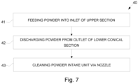
- Step 41 of the method 40 includes feeding the powder into the inlet 3.
- Step 42 of the method 40 includes discharging the powder from the outlet 7.
- the inclination of the ceiling 9 enables the food powder to move downwardly along the ceiling 9 toward the rear wall 8 and downwardly along the rear wall 8 toward the outlet 7.
- Step 43 of the method 40 includes cleaning the powder intake unit 1 via the nozzle 19 mounted to the ceiling 9.
Landscapes
- Engineering & Computer Science (AREA)
- Mechanical Engineering (AREA)
- Basic Packing Technique (AREA)
- Catching Or Destruction (AREA)
- Bag Frames (AREA)
- Nozzles (AREA)
- Filling Or Emptying Of Bunkers, Hoppers, And Tanks (AREA)
Abstract
Description
- The invention relates to a powder intake unit and to a method using the powder intake unit for emptying food powder from a bag.
- Various food ingredients are held in bags, such as sugar, milk powder, salt, flour and other forms of food product in powdery or granular form. During food processing, the powder bags are often transported into a hygienic area in which they are opened by an operator and emptied in a powder intake unit, which may also be referred to as a bag tipping unit. The powder intake unit has an inlet to receive the powder from the bag and an outlet to discharge the powder for further downstream processing.
- Powder intake units typically have a rectangular shape. Rectangular powder intake units may be deficient in handling powder due to the arrangement of the surfaces in the powder intake unit. For example, powder may adhere to interior surfaces such that some of the powder may not be discharged from the powder intake unit for downstream processing. Conventional powder intake units may also be difficult to clean due to the arrangement of the surfaces. The surfaces may be difficult to clean as the cleaning fluid that is sprayed into the powder intake unit is unable to reach all of the surface area of the surfaces.
- It is an object of the invention to at least partly overcome one or more limitations of the prior art. In particular, it is an object to provide a powder intake unit having surfaces that are designed to facilitate removal of powder from the surfaces during cleaning.
- According to a first aspect of the invention, a powder intake unit is configured to receive powder from an opened powder bag. The powder intake unit includes an upper section defining an inlet, and a lower conical section that tapers radially inwardly from a top end at which the lower conical section is connected to the upper section to a bottom end at which an outlet for discharging the powder is arranged. An upper section of the powder intake unit has a rear wall arranged opposite the inlet and a ceiling that is inclined downwardly from the inlet toward the rear wall.
- The powder intake unit described herein is advantageous in that all of the surfaces are inclined relative to a vertical axis of the powder intake unit, such that the powder moves downwardly along the surfaces toward the outlet during operation. The inclined surfaces also facilitate powder removal from the surfaces during cleaning. The cleaning spray is able to move downwardly along the surfaces to remove excess powder from the surfaces. The excess powder and cleaning spray are then drawn out of the powder intake unit.
- According to a second aspect of the invention, a method for emptying food powder from a bag is provided. The method includes feeding the powder into the inlet; and discharging the powder from the outlet, such that food powder inside the powder intake unit moves downwardly toward the outlet.
- Still other objectives, features, aspects and advantages of the invention will appear from the following detailed description as well as from the drawings.
- Embodiments of the invention will now be described, by way of example, with reference to the accompanying schematic drawings.
-
Fig. 1 is a perspective view of a powder intake unit configured to receive powder from an opened powder bag. -
Fig. 2 is a side sectional view of the powder intake unit shown inFig. 1 . -
Fig. 3 is a side view of the powder intake unit shown inFig. 1 . -
Fig. 4 is a front view of the powder intake unit shown inFig. 1 . -
Fig. 5 is a top view of the powder intake unit shown inFig. 1 . -
Fig. 6 is a bottom view of the powder intake unit shown inFig. 1 . -
Fig. 7 is a flow chart of a method for emptying food powder from an opened bag containing food powder using a powder intake unit such as the powder intake unit shown inFig. 1 . - Embodiments of the invention will now be described more fully hereinafter with reference to the accompanying drawings, in which some, but not all, embodiments of the invention are shown. The invention may be embodied in many different forms and should not be construed as limited to the embodiments set forth herein.
- With reference to
Figs. 1-3 , apowder intake unit 1 configured to receive powder from an opened powder bag is illustrated. The powder bag may contain a food ingredient such as sugar, milk powder, salt, flour or other forms of food product in powdery or granular form. Thepowder intake unit 1 is arranged in a hygienic area along a food processing line. Thepowder intake unit 1 may be configured to receive the powder bag from a conveyor or a machine operator, such that the powder bag is provided to thepowder intake unit 1 using an automated process, manual operation, or a combination thereof. The powder is emptied from the powder bag into thepowder intake unit 1 and subsequently discharged from thepowder intake unit 1 for further downstream processing, such as mixing, to produce a food product. - The
powder intake unit 1 is oriented vertically on a ground surface. Thepowder intake unit 1 includes anupper section 2 that defines aninlet 3 configured to receive the powder from the opened powder bag. Theinlet 3 defines a front of thepowder intake unit 1. Thepowder intake unit 1 includes a lowerconical section 4 having atop end 5 at which the lowerconical section 4 is connected to theupper section 2. The lowerconical section 4 has abottom end 6 that is opposite thetop end 5 and has anoutlet 7 for discharging the powder from thepowder intake unit 1. Thetop end 5 and thebottom end 6 may be arranged in horizontal planes. Theoutlet 7 may be circular in shape and defines a vertical axis A which may be a central axis of thepowder intake unit 1. The lowerconical section 4 is tapered radially inwardly from thetop end 5 to thebottom end 6 to define a funnel for the powder. The entire bottom of thepowder intake unit 1 may be defined by theoutlet 7. - The
upper section 2 of thepowder intake unit 1 has arear wall 8 that is arranged opposite theinlet 3 that is at the front of thepowder intake unit 1. Aceiling 9 of theupper section 2 is inclined downwardly from theinlet 3 toward therear wall 8, such that a top end of theinlet 3 is higher than a top end of therear wall 8. Avacuum outlet 10 is arranged on theceiling 9 between therear wall 8 and theinlet 3. Thevacuum outlet 10 is configured for connection to a vacuum for drawing out the cleaning fluid and powder removed from the surfaces of thepowder intake unit 1 during a cleaning operation of thepowder intake unit 1. Thevacuum outlet 10 may be inclined along with theceiling 9 and is arranged at a location along theceiling 9 that is proximate therear wall 8. - The
inlet 3 is opened and closed by adoor 11 that is connected to theupper section 2 byarms 12. Thedoor 11 is hinged to theceiling 9 and connected to arectangular portion 13 of theupper section 2 by thearms 12. Therectangular portion 13 defines theinlet 3 and forms a front of thepowder intake unit 1 opposite therear wall 8. Thearms 12 may be telescoping arms that extend when thedoor 11 is opened away from theinlet 3 and retract when thedoor 11 is closed over theinlet 3. Thedoor 11 is movable in an upward and downward direction. Thedoor 11 has aseal 14 that is arranged along an entirety of the perimeter of thedoor 11. Theseal 14 is configured to mate with theinlet 3 for sealing thedoor 11 and thepowder intake unit 1 when thedoor 11 is closed during operation. Theinlet 3 and theseal 14 have a complementary shape. - When the
door 11 is opened, thedoor 11 is raised above thepowder intake unit 1 such that theinlet 3 is unhindered by thedoor 11 to enable a maximum open area for receiving the powder inside thepowder intake unit 1. Thedoor 11 may be held in the open position by the extendedarms 12 and a hinge having amechanical locking mechanism 15 connected between thedoor 11 and theceiling 9. Theinlet 3 and thedoor 11 may have any suitable shapes. Theinlet 3 and thedoor 11 may be rectangular in shape, such that theseal 14 is also rectangular in shape. Therectangular portion 13 defines part of theceiling 9 that is inclined downwardly from theinlet 3 toward therear wall 8. Therectangular portion 13 defines theinlet 3 that is inclined downwardly from theceiling 9 toward the front of thepowder intake unit 1. - The
powder intake unit 1 is supported above the ground bylegs 16. Thelegs 16 may be attached to the lowerconical section 4 and any number oflegs 16 may be provided. Thepowder intake unit 1 may be supported such that theoutlet 7 is raised slightly above the ground on which thelegs 16 sit. Thepowder intake unit 1 may be supported such that theinlet 3 is positioned at a height that is manually accessible by an operator of thepowder intake unit 1. - A table 17 for the opened powder bag is arranged at the front of the
powder intake unit 1 proximate theinlet 3. The table 17 is horizontal and removably connectable to the front of thepowder intake unit 1. The table 17 may include any suitable releasable mechanical connection to thelegs 16 arranged at the front of thepowder intake unit 1 and theinlet 3. The connection may includelinkages 18 that directly connect the table 17 to thepowder intake unit 1 such that the table 17 is supported above the ground by the connection to thepowder intake unit 1. - As shown in
Figs. 1 and 2 , anozzle 19 is mounted to theceiling 9 and extends downwardly inside theupper section 2. Thenozzle 19 is configured to spray a cleaning fluid into thepowder intake unit 1 for cleaning the inside surfaces of thepowder intake unit 1. Aclamp 20 is provided to clamp thenozzle 19 to theceiling 9. Thenozzle 19 includes aspray ball 21 arranged at an axial end of a pipe of thenozzle 19 inside thepowder intake unit 1. Thespray ball 21 may be arranged at a central location of theupper section 2 to ensure that cleaning spray reaches a maximum area of the surfaces during the cleaning operation. The pipe of thenozzle 19 has a vertical axis B that is offset from the vertical axis A of theoutlet 7. The vertical axis B of thenozzle 19 is arranged between therear wall 8 and the vertical axis A with the vertical axis B being closer to the vertical axis A than therear wall 8. The vertical axis B is offset from the vertical axis A by a distance D that is between 5 and 15 centimeters. The distance between the vertical axes A, B may be approximately 10 centimeters. - The
nozzle 19 extends downwardly through acylindrical portion 22 of theupper section 2 that is connected to therectangular portion 13. Thecylindrical portion 22 defines therear wall 8. The bottom of thecylindrical portion 22 is connected to thetop end 5 of the lowerconical section 4. Thetop end 5 of the lowerconical section 4 lies in a horizontal plane, such that the bottom of thecylindrical portion 22 and thetop end 5 of the lowerconical section 4 meet along the horizontal plane. Atop portion 23 of theupper section 2 is disc-shaped and extends over thecylindrical portion 22 and therectangular portion 13 to define theceiling 9. Therectangular portion 13, thecylindrical portion 22, and thetop portion 23 may be formed integrally as one piece or as separate pieces that are subsequently attached together. - As shown in
Fig. 2 , ends of theinlet 3 and theceiling 9 meet at apoint 30 that is arranged along the vertical axis A defined by theoutlet 7, such that theceiling 9 is arranged on one side of the vertical axis A and theinlet 3 is arranged on the opposite side of the vertical axis A. Therear wall 8 is arranged on the same side of the vertical axis A as theceiling 9. The surface of the lowerconical section 4 extends around the vertical axis A. Thepoint 30 may form a topmost point of thepowder intake unit 1. Thenozzle 19 is arranged between therear wall 8 and thetopmost point 30. - The
inlet 3 may extend downwardly in a direction toward thefront 311 of thepowder intake unit 1. Theinlet 3 may extend downwardly in a direction toward afrontmost end 31, of thepowder intake unit 1. Thefront 311 of thepowder intake unit 1 may be defined as the side of thepowder intake unit 1 where theinlet 3 is arranged. Downwardly may be defined as the direction that is downwards in relation to the vertical direction. - The
inlet 3 may be angled downward toward thefront 311 of thepowder intake unit 1 relative to the vertical axis A by an angle µ that is smaller than 90 degrees, by an angle µ that is smaller than 80 degrees, or by an angle µ that is even smaller. Theinlet 3 may be angled toward thefront 311 of thepowder intake unit 1 relative to the vertical axis A by an angle µ that is between 20 and 60 degrees, or by an angle µ that is between 30 and 60 degrees. The angle µ may be approximately 45 degrees. Theinlet 3 extends downwardly from thetopmost point 30 away from theceiling 9 to thefrontmost end 31 of thepowder intake unit 1. Thefrontmost end 31 also defines a bottom of theinlet 3. The lowerconical section 4 meets theinlet 3 at thefrontmost end 31. The table 17 may be removably connected to thepowder intake unit 1 proximate thefrontmost end 31 such that the table 17 extends horizontally outwardly from thefrontmost end 31. - In contrast to conventional powder intake units that have straight surfaces, such as horizontal ceilings and vertical walls, all of the surfaces of the
powder intake unit 1 are inclined relative to the vertical axes A, B. All of the surfaces being inclined enables the powder to move downwardly along the surfaces toward theoutlet 7 during operation by way of gravity. During cleaning, the inclined surfaces enable the cleaning spray to move downwardly along the surfaces and remove excess powder from the surfaces. The removed powder and cleaning spray is then drawn out of thepowder intake unit 1 by a vacuum. - Each of the
inlet 3, theceiling 9, and the surface of the lowerconical section 4 is inclined by at least 20 degrees relative to the vertical axes A, B. Theceiling 9 is angled downwardly from thetopmost point 30 toward therear wall 8 relative to the vertical axis A by an angle λ. The angle λ is less than 90 degrees and greater than the angle µ between the vertical axis A and theinlet 3. The angle λ may be approximately 60 degrees. Theceiling 9 meets therear wall 8 of thecylindrical portion 22 along acurved portion 32 of theupper section 2. Thecurved portion 32 is defined by thetop portion 23 of theupper section 2 and may form a rearmost portion of thepowder intake unit 1. Theceiling 9 and therear wall 8 may be angled relative to each other by an angle γ that is less than 90 degrees. - The
rear wall 8 is angled relative to the vertical axes A, B of thepowder intake unit 1 by an angle θ that is greater than an angle α by which a surface of the lowerconical section 4 is angled relative to the vertical axes A, B. Each of the angles θ, α may be between 30 and 60 degrees. A length of therear wall 8 extending from theceiling 9 to thetop end 5 of the lowerconical section 4 is less than a length of the surface of the lowerconical section 4 from thebottom end 6 to thetop end 5. The length of therear wall 8 may be less than the length of theinlet 3 from thetopmost point 30 to thefrontmost end 31 and the length of theceiling 9 from thetopmost point 30 to thecurved portion 32. - Referring now to
Fig. 4 , a front view of thepowder intake unit 1 is shown. Theinlet 3 is defined by parallelinclined sides 33 and parallelhorizontal sides horizontal sides inlet 3. Thetopmost point 30 of thepowder intake unit 1 is arranged along the tophorizontal side 34 and thefrontmost end 31 is arranged along the bottomhorizontal side 35. The parallelinclined sides 33 extend from the bottomhorizontal side 35 to the tophorizontal side 34 and are inclined relative to the vertical axis B of thenozzle 20. The parallelhorizontal sides inclined sides 33 to define a width W of theinlet 3. The length of the parallelhorizontal sides - Each of the corners at which one of the
inclined sides 33 meets one of the parallelhorizontal sides inlet 3. The radius of curvature R may be between 5 and 15% of the width W. Each radius of curvature R may be the same along theinlet 3. Theseal 14 and thedoor 11 has a shape that is complementary to the shape of theinlet 3, such that thedoor 11 includes similar radii of curvature to theinlet 3. Providing theinlet 3 with radii of curvature enables a maximum opening area for thepowder intake unit 1 to facilitate emptying of the powder bag. - Referring now to
Fig. 5 , a top view of thepowder intake unit 1 is shown. Thevacuum outlet 10 is formed in a central location of thetop portion 23 of theupper section 2. Thetop portion 23 is continuously formed with therear wall 8 and therectangular portion 24. Theclamp 20 for the nozzle is arranged between therectangular portion 24 and thetop portion 23. Theclamp 20 may be arranged along a horizontal central axis C of thepowder intake unit 1 that is defined from a front end to a back end of thepowder intake unit 1. Thedoor 11 includes ahandle 36 formed on an outside surface of thedoor 11. As shown inFig. 5 , thetop portion 23 of theupper section 2, therectangular section 24, thedoor 11, and the table 17 may have a symmetrical shape about the central axis C. In contrast, theupper section 2 does not have a symmetrical shape about the vertical axis A, as shown inFig. 2 . - Referring now to
Fig. 6 , a bottom view of thepowder intake unit 1 is shown. Thecylindrical portion 22 of theupper section 2 that defines therear wall 8 extends past the lowerconical section 4 in a horizontal direction to define the rearmost end of thepowder intake unit 1. Therectangular portion 24 of theupper section 2 also extends past the lowerconical section 4 in a horizontal direction. Thepowder intake unit 1 includes threelegs 17 that are disposed symmetrically about theoutlet 7 which defines a center of thepowder intake unit 1. - Referring now to
Fig. 7 , amethod 40 for emptying food powder from an opened bag containing food powder using the powder intake unit shown inFigs. 1-6 is shown.Step 41 of themethod 40 includes feeding the powder into theinlet 3.Step 42 of themethod 40 includes discharging the powder from theoutlet 7. During operation, the inclination of theceiling 9 enables the food powder to move downwardly along theceiling 9 toward therear wall 8 and downwardly along therear wall 8 toward theoutlet 7.Step 43 of themethod 40 includes cleaning thepowder intake unit 1 via thenozzle 19 mounted to theceiling 9. - While the invention has been described with reference to one or more preferred features, which features have been set forth in considerable detail for the purposes of making a complete disclosure of the invention, such features are merely exemplary and are not intended to be limiting or represent an exhaustive enumeration of all aspects of the invention. The scope of the invention, therefore, shall be defined solely by the following claims. Further, it will be apparent to those of skill in the art that numerous changes may be made in such details without departing from the spirit and the principles of the invention.
Claims (15)
- A powder intake unit (1) configured to receive powder from an opened powder bag, the powder intake unit (1) comprising:an upper section (2) defining an inlet (3) for receiving the powder; anda lower conical section (4) that tapers radially inwardly from a top end (5) at which the lower conical section (4) is connected to the upper section (2) to a bottom end (6) at which an outlet (7) for discharging the powder is arranged,characterized bythe upper section (2) having a rear wall (8) arranged opposite the inlet (3) and a ceiling (9) that is inclined downwardly from the inlet (3) toward the rear wall (8).
- The powder intake unit (1) according to claim 1, comprising a nozzle (19) mounted to the ceiling (9) and extending downwardly inside the upper section (2) for cleaning the powder intake unit (1).
- The powder intake unit (1) according to claim 2, wherein a vertical axis (A) of the outlet (7) is offset from a vertical axis (B) of the nozzle (19).
- The powder intake unit (1) according to claim 3, wherein the vertical axis (B) of the nozzle (19) is arranged between the rear wall (8) and the vertical axis (A) of the outlet (7).
- The powder intake unit (1) according to any preceding claim, wherein the inlet (3) and the ceiling (9) meet at a point (30) arranged along a vertical axis (A) of the outlet (7).
- The powder intake unit (1) according to any preceding claim, comprising a vacuum outlet (10) arranged on the ceiling (9).
- The powder intake unit (1) according to any preceding claim, comprising a door (11) for closing the inlet (3), the door (11) connected to the ceiling (9) and having a seal (14) configured to mate with the inlet (3).
- The powder intake unit (1) according to any preceding claim, wherein the inlet (3) is defined by parallel inclined sides (33) that extend between a horizontal top side (34) and a horizontal bottom side (35) of the inlet (3), such that the inlet has four corners, wherein each corner has a radius (R) between 5 and 15 percent of a width (W) of the inlet (3), the width (W) being defined by a distance between the parallel inclined sides (33).
- The powder intake unit (1) according to any preceding claim, wherein each of the inlet (3), the ceiling (9), and a surface of the lower conical section (4) is inclined by at least 20 degrees relative to a vertical axis (A, B) of the powder intake unit (1).
- The powder intake unit (1) according to any preceding claim, wherein the rear wall (8) is inclined inwardly from the ceiling (9) toward the lower conical section (4).
- The powder intake unit (1) according to any preceding claim, wherein the rear wall (8) is angled relative to a vertical axis (A, B) of the powder intake unit (1) by an angle (θ) that is greater than an angle (α) by which a surface of the lower conical section (4) is angled relative to the vertical axis (A, B).
- The powder intake unit (1) according to any preceding claim, wherein the upper section (2) has a cylindrical portion (22) that defines the rear wall (8).
- The powder intake unit (1) according to any preceding claim, comprising a table (17) removably connected to a frontmost end (31) of the powder intake unit (1) at which the inlet (3) meets the top end (5) of the lower conical section (4).
- A method (40) for emptying food powder from a bag, the method (40) using a powder intake unit (1) according to any preceding claim and comprising:feeding (41) the powder into the inlet (3); anddischarging (42) the powder from the outlet (7), such that food powder inside the powder intake unit (1) moves downwardly toward the outlet (7).
- The method (40) according to claim 14, comprising cleaning (43) the powder intake unit (1) by feeding cleaning liquid through the nozzle (19).
Applications Claiming Priority (1)
| Application Number | Priority Date | Filing Date | Title |
|---|---|---|---|
| EP21211437 | 2021-11-30 |
Publications (2)
| Publication Number | Publication Date |
|---|---|
| EP4186803A2 true EP4186803A2 (en) | 2023-05-31 |
| EP4186803A3 EP4186803A3 (en) | 2023-08-16 |
Family
ID=78820066
Family Applications (1)
| Application Number | Title | Priority Date | Filing Date |
|---|---|---|---|
| EP22209776.8A Pending EP4186803A3 (en) | 2021-11-30 | 2022-11-28 | Powder intake unit |
Country Status (4)
| Country | Link |
|---|---|
| US (1) | US20250033815A1 (en) |
| EP (1) | EP4186803A3 (en) |
| CN (1) | CN118339080A (en) |
| WO (1) | WO2023099379A1 (en) |
Family Cites Families (10)
| Publication number | Priority date | Publication date | Assignee | Title |
|---|---|---|---|---|
| US2293160A (en) * | 1941-08-14 | 1942-08-18 | Du Pont | Portable container for calcium carbide and the like |
| GB1248035A (en) * | 1968-01-03 | 1971-09-29 | Alcoa Container Syst | Improvements in or relating to containers for materials in bulk |
| US4541549A (en) * | 1983-03-18 | 1985-09-17 | Deere & Company | Agricultural hopper structure |
| US5226775A (en) * | 1990-12-24 | 1993-07-13 | L. B. Bohle Pharmatechnik Gmbh | Method of and apparatus for conveying and storing tablets, pills and like products |
| US5992699A (en) * | 1998-08-07 | 1999-11-30 | Deere & Company | Multifaceted product tank |
| HUE026139T2 (en) * | 2011-03-11 | 2016-05-30 | Bayer Ip Gmbh | Mixing silo |
| EP3096869B1 (en) * | 2014-01-20 | 2018-06-20 | Johnson Matthey Process Technologies, Inc. | System for adding material to one or more units |
| PL3196136T3 (en) * | 2016-01-20 | 2019-07-31 | Inversiones Hiki6, S.L. | Method and modular, mobile mixing and packaging plant |
| CN214397468U (en) * | 2021-01-27 | 2021-10-15 | 天津中益包装科技股份有限公司 | Feeding mechanism of hangers coffee packaging machine |
| CN113291880A (en) * | 2021-07-07 | 2021-08-24 | 上海威泽尔机械设备制造有限公司 | Feeding station with small broken block bags |
-
2022
- 2022-11-28 WO PCT/EP2022/083417 patent/WO2023099379A1/en not_active Ceased
- 2022-11-28 CN CN202280079470.4A patent/CN118339080A/en active Pending
- 2022-11-28 US US18/713,727 patent/US20250033815A1/en active Pending
- 2022-11-28 EP EP22209776.8A patent/EP4186803A3/en active Pending
Also Published As
| Publication number | Publication date |
|---|---|
| US20250033815A1 (en) | 2025-01-30 |
| WO2023099379A1 (en) | 2023-06-08 |
| EP4186803A3 (en) | 2023-08-16 |
| CN118339080A (en) | 2024-07-12 |
Similar Documents
| Publication | Publication Date | Title |
|---|---|---|
| JP2003516287A (en) | Steel container especially intended for the transportation of large goods | |
| US20200139389A1 (en) | Feed center for dense phase system | |
| US5130093A (en) | Cleaning and sterilizing machine for articles, such as closure elements for pharmaceutical containers | |
| CN101827767B (en) | Material separator for delivery systems | |
| US8118944B2 (en) | Self-cleaning pill counting device, and cleaning method | |
| US20250033815A1 (en) | Powder intake unit | |
| JPH0228306B2 (en) | ||
| US12389921B2 (en) | Nozzle arrangement for a powder handling apparatus | |
| US20010030202A1 (en) | Dry particulate dispenser | |
| CN110520360A (en) | round dispensing equipment | |
| CN113940547B (en) | Flour cooking system | |
| US20110048317A1 (en) | Portable, compact, food seasoning replenishment system | |
| US2894664A (en) | Fluid dispensing apparatus | |
| US20220046932A1 (en) | Apparatus for Mixing Powdery Baking Ingredients with Water | |
| CN108298321B (en) | Multi-stage material conveying equipment | |
| CN211159506U (en) | Even compounding system that piles of light material | |
| CN108067146A (en) | Material mixing equipment | |
| US20180148255A1 (en) | Apparatus for bulk handling | |
| US20090261125A1 (en) | Container including valve assembly for storing liquids containing solids | |
| WO2016191801A1 (en) | Mixing apparatus | |
| NL2011126C2 (en) | Blender for particulate materials. | |
| CN222273330U (en) | Leak protection material conveyor | |
| CN109692606B (en) | Even heap compounding system of light material | |
| CN211223948U (en) | Split charging device convenient for fermentation of food raw materials | |
| CN208532638U (en) | A kind of production line of powdered modified explosive |
Legal Events
| Date | Code | Title | Description |
|---|---|---|---|
| PUAI | Public reference made under article 153(3) epc to a published international application that has entered the european phase |
Free format text: ORIGINAL CODE: 0009012 |
|
| STAA | Information on the status of an ep patent application or granted ep patent |
Free format text: STATUS: THE APPLICATION HAS BEEN PUBLISHED |
|
| AK | Designated contracting states |
Kind code of ref document: A2 Designated state(s): AL AT BE BG CH CY CZ DE DK EE ES FI FR GB GR HR HU IE IS IT LI LT LU LV MC ME MK MT NL NO PL PT RO RS SE SI SK SM TR |
|
| PUAL | Search report despatched |
Free format text: ORIGINAL CODE: 0009013 |
|
| AK | Designated contracting states |
Kind code of ref document: A3 Designated state(s): AL AT BE BG CH CY CZ DE DK EE ES FI FR GB GR HR HU IE IS IT LI LT LU LV MC ME MK MT NL NO PL PT RO RS SE SI SK SM TR |
|
| RIC1 | Information provided on ipc code assigned before grant |
Ipc: B65D 90/00 20060101ALI20230711BHEP Ipc: B08B 9/093 20060101ALI20230711BHEP Ipc: B65B 69/00 20060101ALI20230711BHEP Ipc: B08B 3/02 20060101ALI20230711BHEP Ipc: B05B 1/02 20060101ALI20230711BHEP Ipc: B65B 37/02 20060101AFI20230711BHEP |
|
| STAA | Information on the status of an ep patent application or granted ep patent |
Free format text: STATUS: REQUEST FOR EXAMINATION WAS MADE |
|
| 17P | Request for examination filed |
Effective date: 20240216 |
|
| RBV | Designated contracting states (corrected) |
Designated state(s): AL AT BE BG CH CY CZ DE DK EE ES FI FR GB GR HR HU IE IS IT LI LT LU LV MC ME MK MT NL NO PL PT RO RS SE SI SK SM TR |