EP4186752A1 - Imaging-apparatus attachment device - Google Patents
Imaging-apparatus attachment device Download PDFInfo
- Publication number
- EP4186752A1 EP4186752A1 EP21846299.2A EP21846299A EP4186752A1 EP 4186752 A1 EP4186752 A1 EP 4186752A1 EP 21846299 A EP21846299 A EP 21846299A EP 4186752 A1 EP4186752 A1 EP 4186752A1
- Authority
- EP
- European Patent Office
- Prior art keywords
- bracket
- engaging
- hood
- lens hood
- lens
- Prior art date
- Legal status (The legal status is an assumption and is not a legal conclusion. Google has not performed a legal analysis and makes no representation as to the accuracy of the status listed.)
- Pending
Links
Images




Classifications
-
- B—PERFORMING OPERATIONS; TRANSPORTING
- B60—VEHICLES IN GENERAL
- B60R—VEHICLES, VEHICLE FITTINGS, OR VEHICLE PARTS, NOT OTHERWISE PROVIDED FOR
- B60R11/00—Arrangements for holding or mounting articles, not otherwise provided for
- B60R11/04—Mounting of cameras operative during drive; Arrangement of controls thereof relative to the vehicle
-
- G—PHYSICS
- G03—PHOTOGRAPHY; CINEMATOGRAPHY; ANALOGOUS TECHNIQUES USING WAVES OTHER THAN OPTICAL WAVES; ELECTROGRAPHY; HOLOGRAPHY
- G03B—APPARATUS OR ARRANGEMENTS FOR TAKING PHOTOGRAPHS OR FOR PROJECTING OR VIEWING THEM; APPARATUS OR ARRANGEMENTS EMPLOYING ANALOGOUS TECHNIQUES USING WAVES OTHER THAN OPTICAL WAVES; ACCESSORIES THEREFOR
- G03B11/00—Filters or other obturators specially adapted for photographic purposes
- G03B11/04—Hoods or caps for eliminating unwanted light from lenses, viewfinders or focusing aids
- G03B11/045—Lens hoods or shields
-
- G—PHYSICS
- G03—PHOTOGRAPHY; CINEMATOGRAPHY; ANALOGOUS TECHNIQUES USING WAVES OTHER THAN OPTICAL WAVES; ELECTROGRAPHY; HOLOGRAPHY
- G03B—APPARATUS OR ARRANGEMENTS FOR TAKING PHOTOGRAPHS OR FOR PROJECTING OR VIEWING THEM; APPARATUS OR ARRANGEMENTS EMPLOYING ANALOGOUS TECHNIQUES USING WAVES OTHER THAN OPTICAL WAVES; ACCESSORIES THEREFOR
- G03B17/00—Details of cameras or camera bodies; Accessories therefor
- G03B17/02—Bodies
-
- G—PHYSICS
- G03—PHOTOGRAPHY; CINEMATOGRAPHY; ANALOGOUS TECHNIQUES USING WAVES OTHER THAN OPTICAL WAVES; ELECTROGRAPHY; HOLOGRAPHY
- G03B—APPARATUS OR ARRANGEMENTS FOR TAKING PHOTOGRAPHS OR FOR PROJECTING OR VIEWING THEM; APPARATUS OR ARRANGEMENTS EMPLOYING ANALOGOUS TECHNIQUES USING WAVES OTHER THAN OPTICAL WAVES; ACCESSORIES THEREFOR
- G03B30/00—Camera modules comprising integrated lens units and imaging units, specially adapted for being embedded in other devices, e.g. mobile phones or vehicles
-
- H—ELECTRICITY
- H04—ELECTRIC COMMUNICATION TECHNIQUE
- H04N—PICTORIAL COMMUNICATION, e.g. TELEVISION
- H04N23/00—Cameras or camera modules comprising electronic image sensors; Control thereof
- H04N23/50—Constructional details
-
- H—ELECTRICITY
- H04—ELECTRIC COMMUNICATION TECHNIQUE
- H04N—PICTORIAL COMMUNICATION, e.g. TELEVISION
- H04N23/00—Cameras or camera modules comprising electronic image sensors; Control thereof
- H04N23/50—Constructional details
- H04N23/51—Housings
-
- B—PERFORMING OPERATIONS; TRANSPORTING
- B60—VEHICLES IN GENERAL
- B60R—VEHICLES, VEHICLE FITTINGS, OR VEHICLE PARTS, NOT OTHERWISE PROVIDED FOR
- B60R11/00—Arrangements for holding or mounting articles, not otherwise provided for
- B60R2011/0001—Arrangements for holding or mounting articles, not otherwise provided for characterised by position
- B60R2011/0003—Arrangements for holding or mounting articles, not otherwise provided for characterised by position inside the vehicle
- B60R2011/0026—Windows, e.g. windscreen
-
- G—PHYSICS
- G03—PHOTOGRAPHY; CINEMATOGRAPHY; ANALOGOUS TECHNIQUES USING WAVES OTHER THAN OPTICAL WAVES; ELECTROGRAPHY; HOLOGRAPHY
- G03B—APPARATUS OR ARRANGEMENTS FOR TAKING PHOTOGRAPHS OR FOR PROJECTING OR VIEWING THEM; APPARATUS OR ARRANGEMENTS EMPLOYING ANALOGOUS TECHNIQUES USING WAVES OTHER THAN OPTICAL WAVES; ACCESSORIES THEREFOR
- G03B11/00—Filters or other obturators specially adapted for photographic purposes
- G03B11/04—Hoods or caps for eliminating unwanted light from lenses, viewfinders or focusing aids
Definitions
- the present disclosure relates to an imaging device for a mounting device provided for an imaging device mounted, for example, on a window glass of a vehicle.
- An imaging device for a vehicle is mounted on a surface, of a pair of surfaces having a windshield glass, that is one example of a window glass, inside a vehicle cabin.
- An imaging device is used to detect the presence or absence of another vehicle or an obstacle positioned in front of an own vehicle.
- An imaging device is provided with a bracket secured to a windshield glass, a first housing supported by the bracket, a camera unit supported by the first housing, and a hood mounted on the first housing.
- the hood has a substantially triangular shape that widens in a direction away from the camera unit in front of a lens provided on the camera unit (for example, see Patent Document 1).
- An imaging device is provided with a securing bracket secured to a windshield glass, a camera unit, and a camera bracket that secures the camera unit to the securing bracket.
- a hood part having a substantially triangular shape that widens in a direction away from the camera unit in front of a lens provided on the camera unit is integrally molded to the securing bracket. That is, with the imaging device according to the second example, the hood part, which corresponds to the hood provided on the imaging device according to the first example, is integrated with the securing bracket (for example, see Patent Document 2).
- the imaging device With the imaging device according to the first example, because a lens is assembled to an end of a hood mounted on a first housing, a camera unit must be removed from the first housing before the hood when removing the hood from the imaging device. Furthermore, with the imaging device according to the second example, because a hood is integrated with a securing bracket, the hood cannot be removed from the imaging device while the imaging device is mounted on a windshield.
- An object of the present disclosure is to provide an imaging device for a mounting device that makes it easy to remove a hood.
- an imaging device for a mounting device comprises a bracket supporting a camera unit having a light receiving unit, and configured to be mounted on an attachment subject, and a hood having a surface expanding in a direction away from the light receiving unit in front of the light receiving unit, and mounted on the bracket so that the surface faces the attachment subject, wherein the hood can be removed from the bracket along the attachment subject while the camera unit is being supported by the bracket.
- FIG. 1 through FIG. 6 A first embodiment of an imaging device for a mounting device will be described with reference to FIG. 1 through FIG. 6 .
- An imaging device for a vehicle 10 illustrated in FIG. 1 is mounted on an attachment subject and receives light incident through the attachment subject.
- the attachment subject is a surface of a transparent member that is optically transparent and transmits visible light, and is, for example, a surface inside a vehicle cabin on a window glass for a vehicle.
- the imaging device for a vehicle 10 is mounted on a surface of a pair of surfaces of the window glass included inside a vehicle cabin.
- the window glass is, for example, a windshield glass, but may also be a sunroof glass, a rear glass, or the like.
- the imaging device for a vehicle 10 includes a camera unit 11 and a mounting device 12.
- the camera unit 11 includes a camera body 11A, and a lens 11B, which is one example of a light receiving unit.
- the camera body 11A includes, for example, an imaging element, a recording element, and a housing, and the like, in which these elements are housed.
- the lens 11B is exposed outside the camera body 11A and receives light incident through the attachment subject.
- the mounting device 12 is a device for mounting the camera unit 11 to the attachment subject.
- the mounting device 12 includes a bracket 21 and a lens hood 22.
- the bracket 21 supports the camera unit 11 that includes the lens 11B.
- the bracket 21 is mounted on the attachment subject while supporting the camera unit 11.
- the lens hood 22 includes a surface 22F that expands in a direction away from the lens 11B in front of the lens 11B.
- the lens hood 22 is mounted on the bracket 21 so that the surface 22F faces the attachment subject.
- the lens hood 22 can be removed from the bracket 21 along the attachment subject while the camera unit 11 is being supported by the bracket 21.
- the lens hood 22 can be removed along the attachment subject from the bracket 21 supporting the camera unit 11, the lens hood 22 can be removed without removing the camera unit 11 or the entire mounting device 12. Therefore, the lens hood 22 can be removed easily.
- the lens hood 22 can, while the camera unit 11 is mounted on the bracket 21, be mounted on the bracket 21 along a direction opposite a direction in which the lens hood 22 is removed. Therefore, because the lens hood 22 can be mounted along the attachment subject to the bracket 21 supporting the camera unit 11, mounting the lens hood 22 does not require removal of the camera unit 11 or the entire mounting device 12. Therefore, the lens hood 22 can be mounted easily.
- Each member included in the imaging device for a vehicle 10 is described in detail below with reference to FIG. 1 .
- the camera body 11A included in the camera unit 11 has an outer shape in which a substantially L-shaped cross-sectional shape is continuous along a left-right direction of the imaging device for a vehicle 10.
- the camera unit 11 includes a first right engaging part 11R1, a second right engaging part 11R2, a first left engaging part 11L1, and a second left engaging part 11L2.
- a pair of the right engaging parts 11R1 and 11R2 has a columnar shape protruding in the left-right direction from a right side surface of the camera body 11A.
- a pair of the left engaging parts 11L1 and 11L2 has a columnar shape protruding in the left-right direction from a left side surface of the camera body 11A.
- a pair of the first engaging parts 11R1 and 11L1 extends along the same central axis.
- a pair of the second engaging parts 11R2 and 11L2 extends along the same central axis in a different position than the pair of first engaging parts 11R1 and 11L1.
- the pair of second engaging parts 11R2 and 11L2 is positioned in front of the pair of first engaging parts 11R1 and 11L1.
- the bracket 21 is mounted on the attachment subject by a mounting member such as an adhesive member, a fastening member, or the like.
- the bracket 21 is a resin molded product formed using synthetic resin.
- the bracket 21 includes a right engaging leg 21LR and a left engaging leg 21LL. A pair of the engaging legs 21LR and 21LL is aligned in the left-right direction in the bracket 21 with a gap therebetween.
- Each of the engaging legs 21LR and 21LL is shaped extending along a front-rear direction.
- the right engaging leg 21LR includes a first right engaging groove LR1 and a second right engaging groove LR2.
- the left engaging leg 21LL includes a first left engaging groove LL1 and a second left engaging groove LL2.
- a pair of the first engaging grooves LR1 and LL1 is positioned on the same axis extending in the left-right direction.
- a pair of the second engaging grooves LR2 and LL2 is positioned on the same axis extending in the left-right direction.
- the pair of second engaging grooves LR2 and LL2 is positioned in front the pair of first engaging grooves LR1 and LL1.
- the first right engaging part 11R1 is fitted into the first right engaging groove LR1, and the first left engaging part 11L1 is fitted into the first left engaging groove LL1. Furthermore, the second right engaging part 11R2 is fitted into the second right engaging groove LR2, and the second left engaging part 11L2 is fitted into the second left engaging groove LL2. This results in the bracket 21 supporting the camera unit 11.
- the bracket 21 includes a right engaging hole 21HR that passes through the right engaging leg 21LR.
- the right engaging hole 21HR is positioned midway along the front-rear direction in the right engaging leg 21LR.
- the right engaging hole 21HR is positioned above the first right engaging groove LR1 and the second right engaging groove LR2, which are on the right engaging leg 21LR.
- the bracket 21 also includes a left engaging piece 21PL and a left guiding strip 21BL.
- the left engaging piece 21PL is positioned on, of a pair of sides extending in the left-right direction on the bracket 21, the rearward of these sides.
- the left engaging piece 21PL and the left guiding strip 21BL are positioned above the first left engaging groove LL1 and the second engaging groove LL2, which are on the left engaging leg 21LL.
- the left guiding strip 21BL is positioned below the left engaging piece 21PL.
- the left engaging piece 21PL is rectangular extending along the front-rear direction and projects into an opening defined by the bracket 21.
- the left guiding strip 21BL is positioned on, in a pair of sides extending in the left-right direction on the bracket 21, the rearward of these sides.
- the left guiding strip 21BL extends along the left-right direction from a left end on said side.
- bracket 21 includes a right leg engaging hole and a left leg engaging hole that are not illustrated in the drawings (see FIG. 4 ).
- the lens hood 22 is a resin molded product formed using synthetic resin.
- the lens hood 22 includes a hood body 22A.
- the hood body 22A is substantially trapezoidal and includes a surface 22F.
- the surface 22F is a surface of the lens hood 22 that faces the attachment subject when the imaging device for a vehicle 10 is mounted on the attachment subject.
- a rear surface 22R is a surface on the hood body 22A on a side opposite the surface 22F.
- the lens hood 22 includes a right wall part 22WR and a left wall part 22WL.
- the right wall part 22WR is substantially L-shaped along a right diagonal side of and part of an upper base on the hood body 22A.
- the left wall part 22WL is substantially L-shaped along a left diagonal side of and part of an upper base on the hood body 22A.
- the lens 11B of the camera unit 11 is positioned between the pair of wall parts 22WR and 22WL when the lens hood 22 is supported by the bracket 21. Therefore, the hood body 22A is shaped expanding in front of the lens 11B in a direction away from the lens 11B.
- the lens hood 22 includes a right engaging protrusion 22PR, a left engaging protrusion 22PL, a right engaging leg 22LR, and a left engaging leg 22LL.
- the right engaging protrusion 22PR protrudes from the hood body 22A and is thus shaped so as to extend along the direction in which the lens hood 22 is removed. By engaging with the bracket 21, the right engaging protrusion 22PR engages the hood body 22A to the bracket 21.
- the right engaging protrusion 22PR is one example of a first engaging part.
- the right engaging protrusion 22PR is connected to a rear right end of the hood body 22A.
- the right engaging protrusion 22PR is rectangular extending along the left-right direction.
- the left engaging protrusion 22PL is one example of a second engaging part.
- the left engaging protrusion 22PL is connected to a rear left end of the hood body 22A.
- the left engaging protrusion 22PL is rectangular extending along the front-rear direction and protrudes from the hood body 22A in the front-rear direction. By engaging with the bracket 21, the left engaging protrusion 22PL engages the hood body 22A to the bracket 21.
- the left engaging protrusion 22PL extends along a direction that intersects a direction in which the right engaging protrusion 22PR extends.
- the lens hood 22 is mounted on the bracket 21, the lens hood 22 is inserted into the bracket 21 along, in the same way as when removed, the attachment subject and the left-right direction.
- a direction in which the lens hood 22 slides when mounted, and a direction in which the lens hood 22 slides when removed are oriented opposite one another. That is, the direction in which the lens hood 22 slides when mounted is a direction on the bracket 21 from the left engaging leg 21LL to the right engaging leg 21LR.
- the direction in which the lens hood 22 slides when removed is a direction on the bracket 21 from the right engaging leg 21LR to the left engaging leg 21LL.
- the lens hood 22 slides in the direction from the right engaging leg 21LR to the left engaging leg 21LL when the lens hood 22 is mounted on the bracket 21, the left engaging protrusion 22PL is positioned behind the right engaging protrusion 22PR in a direction in which the lens hood 22 is mounted.
- the lens hood 22 can be mounted on the bracket 21 by both the right engaging protrusion 22PR and the left engaging protrusion 22PL by mounting the lens hood 22 along the attachment subject.
- the lens hood 22 can be mounted on the bracket 21 more securely than in a case where the lens hood 22 is mounted on the bracket 21 by one engaging part.
- the right engaging leg 22LR is connected to the rear surface 22R of the hood body 22A.
- the right engaging leg 22LR protrudes along an up-down direction from a front side on the hood body 22A.
- the right engaging leg 22LR is substantially L-shaped in a cross section along a surface prescribed by the left-right direction and the up-down direction, and the L-shaped cross section has a shape that continues along the front-rear direction.
- the left engaging leg 22LL is connected to the rear surface 22R of the hood body 22A.
- the left engaging leg 22LL protrudes along the up-down direction from a front left end on the hood body 22A.
- the left engaging leg 22LL is substantially L-shaped in a cross section along a surface prescribed by the left-right direction and the up-down direction, and the L-shaped cross section has a shape that continues along the front-rear direction.
- the right engaging leg 22LR is fitted into the right leg engaging hole (see FIG. 4 ) described above, and the left engaging leg 22LL is fitted into the left leg engaging hole described above. This results in the lens hood 22 being supported by the bracket 21.
- the mounting device 12 includes a heating unit 23.
- the heating unit 23 is substantially trapezoidal.
- a width of the heating unit 23 in the left-right direction is about the same as a width of the hood body 22A.
- a width of the heating unit 23 in the front-rear direction is about the same as a width of the hood body 22A.
- An area to be heated by the heating unit 23 is about the same shape and size as an external form of the heating unit 23.
- the heating unit 23 may be, for example, a planar heating element.
- the heating unit 23 includes, for example, a planar good conductor, a current-carrying unit, and a pair of insulating films.
- the current-carrying unit is formed of a single heating wire and is connected to a supplying unit not illustrated in the drawings.
- the current-carrying unit is sandwiched between the pair of insulating films.
- the planar good conductor is affixed on one of the insulating films.
- the supplying unit is electrically connected to the heating unit 23 and supplies electric current to the heating unit 23.
- the heating unit 23 is affixed to the rear surface 22R of the hood body 22A by an adhesive, a glue, and the like.
- FIG. 2 illustrates the imaging device for a vehicle 10 in an assembled state.
- the camera unit 11 is first mounted on the pair of engaging legs 21LR and 21LL included on the bracket 21.
- sliding the lens hood 22 along the left-right direction slides the left engaging protrusion 22PL along the left guiding strip 21BL of the bracket 21 while inserting the right engaging protrusion 22PR of the lens hood 22 into the right engaging hole 21HR of the bracket 21.
- the right engaging leg 22LR of the lens hood 22 is fitted into the right leg engaging hole (see FIG. 4 ) of the bracket 21, and the left engaging leg 22LL of the lens hood 22 is fitted into the left leg engaging hole (see FIG. 4 ) of the bracket 21.
- a gap G in the front-rear direction between the camera body 11A that supports the lens 11B and the lens hood 22 is larger than an amount by which the lens 11B protrudes from the camera body 11A. Therefore, the camera unit 11 does not interfere with sliding of the lens hood 22 when the camera unit 11 is mounted on the bracket 21. That is, the camera unit 11 does not hinder the sliding of the lens hood 22. Therefore, the lens hood 22 can be mounted on the bracket 21 to which the camera unit 11 has been mounted.
- the lens hood 22 when the lens hood 22 is mounted on the bracket 21 for the first time, the camera unit 11 is mounted on the bracket 21, the bracket 21 supporting the camera unit 11 is mounted on the attachment subject, and then, the lens hood 22 is mounted on the bracket 21. Or, the camera unit 11 and the lens hood 22 may be mounted on the bracket 21 in that order, and then, the bracket 21 may be mounted on the attachment subject. In either case, the lens hood 22 can be mounted on the bracket 21 while the camera unit 11 is mounted on the bracket 21.
- the lens hood 22 can also be removed from the bracket 21 mounted on the attachment subject. Because, as is described above, the camera unit 11 does not hinder the sliding of the lens hood 22, the lens hood 22 can be removed from the bracket 21 while the camera unit 11 is mounted on the bracket 21. Because the surface 22F of the lens hood 22 faces the attachment subject while the imaging device for a vehicle 10 is mounted on the attachment subject, the lens hood 22 can be removed along the attachment subject by sliding the lens hood 22 along the left-right direction. For example, the lens hood 22 removed from the bracket 21 for maintenance, or the like, can be remounted on the bracket 21 mounted on the attachment subject.
- the bracket 21 supports part of the camera unit 11 on a side opposite the attachment subject with respect to the lens hood 22 while the camera unit 11 and the lens hood 22 are mounted on the bracket 21. Because, as is described above, the lens hood 22 can be removed along the attachment subject, the lens hood 22 can be removed from the bracket 21, even if part of the camera unit 11 is positioned on a side opposite the attachment subject with respect to the lens hood 22.
- FIG. 3 illustrates a planar structure of the imaging device for a vehicle 10 as seen from a viewpoint facing the rear surface 22R of the lens hood 22. Note that in FIG. 3 through FIG. 6 , which will be referenced below, the left-right direction is reversed from that in FIG. 1 and FIG. 2 for the convenience of illustration. Also, illustration of the camera unit 11 is omitted in FIG. 3 through FIG. 6 for the convenience of illustration.
- FIG. 4 illustrates an end surface structure along line IV-IV illustrated in FIG. 3 .
- FIG. 5 illustrates an end surface structure along line V-V illustrated in FIG. 3 .
- FIG. 6 illustrates an end surface structure along line VI-VI illustrated in FIG. 3 .
- the right engaging protrusion 22PR, the left engaging protrusion 22PL, the right engaging leg 22LR, and the left engaging leg 22LL included on the lens hood 22 are all supported by the bracket 21.
- the structure where the right engaging protrusion 22PR, the left engaging protrusion 22PL, the right engaging leg 22LR, and the left engaging leg 22LL are all supported by the bracket 21 is described in greater detail below with reference to FIG. 4 to FIG. 6 .
- FIG. 4 illustrates a structure where the right engaging leg 22LR and the left engaging leg 22LL of the lens hood 22 are supported by the bracket 21.
- the bracket 21 includes a right leg engaging hole HLR and a left leg engaging hole HLL that pass through the bracket 21 in the left-right direction.
- the right engaging leg 22LR is fitted into the right leg engaging hole HLR and the left engaging leg 22LL is fitted into the left leg engaging hole HLL.
- the left engaging leg 22LL fits into the left leg locking hold HLL so as to be able to slide in the left-right direction with respect to the left leg engaging hole HLL. Therefore, the left engaging leg 22LL can be removed from the left leg engaging hole HLL simply by sliding the lens hood 22 in the left-right direction.
- the right engaging leg 22LR is restricted from sliding in the left-right direction by the bracket 21.
- the slide restriction by the bracket 21 can be released by pushing up from below on a portion of the right engaging leg 22LR that has passed through the right leg engaging hole HLR.
- the right engaging leg 22LR can be removed from the right leg engaging hole HLR by pushing up on the portion of the right engaging leg 22LR that has passed through the right leg engaging hole HLR and sliding the lens hood 22 in the left-right direction while maintaining an upward pushing state.
- FIG. 5 illustrates a structure where the right engaging protrusion 22PR of the lens hood 22 is supported by the bracket 21.
- the right engaging protrusion 22PR is fitted into the right engaging hole 21HR while the lens hood 22 is mounted on the bracket 21.
- the right engaging protrusion 22PR is thus restricted from sliding in the left-right direction by the bracket 21.
- the slide restriction by the bracket 21 can be released by pushing up from below on a portion of the right engaging protrusion 22PR that has passed through the right engaging hole 21HR.
- the right engaging protrusion 22PR can be removed from the right engaging hole 21HR by sliding the lens hood 22 in the left-right direction while maintaining a state of pushing upward on the portion of the right engaging protrusion 22PR that has passed through the right engaging hole 21HR.
- FIG. 6 illustrates a structure where the left engaging protrusion 22PL of the lens hood 22 is supported by the bracket 21.
- the left engaging protrusion 22PL is sandwiched between the left engaging piece 21PL and the left guiding strip 21BL in the up-down direction. Because the left engaging protrusion 22PL is sandwiched between the left engaging piece 21PL and the left guiding strip 21BL in a state where the left engaging protrusion 22PL can be slid in the left-right direction, the left engaging protrusion 22PL can be moved to the left of the left engaging piece 21PL just by sliding the lens hood 22 in the left-right direction.
- a second embodiment of the imaging device mounting device will be described with reference to FIG. 7 through FIG. 13 .
- a lens hood is slid in a different direction with respect to a bracket than in the first embodiment described above. Therefore, points that differ from the first embodiment will be described in particular detail below.
- an imaging device for a vehicle 30 illustrated in FIG. 7 is mounted on an attachment subject and receives light incident through the attachment subject.
- the attachment subject is a transparent member that is optically transparent and transmits visible light, and is, for example, a window glass for a vehicle.
- the imaging device for a vehicle 10 is mounted on a surface, in a pair of surfaces the window glass includes, inside a vehicle cabin.
- the window glass is, for example, a windshield glass, but may also be a sunroof glass, a rear glass, or the like.
- the imaging device for a vehicle 30 includes a camera unit 31 and a mounting device 32.
- the camera unit 31 includes a camera body 31A and a lens 31B, which is one example of a light receiving unit.
- the camera body 31A includes, for example, an imaging element, a recording element, a housing, and the like, in which these elements are housed.
- the lens 31B is exposed outside the camera body 31A and receives light incident through the attachment subject.
- the mounting device 32 is a device for mounting the camera unit 31 to the attachment subject.
- the mounting device 32 includes a bracket 41 and a lens hood 42.
- the bracket 41 supports the camera unit 31 that includes the lens 31B.
- the bracket 41 is mounted on the attachment subject while supporting the camera unit 31.
- the lens hood 42 includes a surface 42F that expands in a direction away from the lens 31B in front of the lens 31B.
- the lens hood 42 is mounted on the bracket 41 so that the surface 42F faces the attachment subject.
- the lens hood 42 can be removed from the bracket 41 along the attachment subject while the camera unit 31 is being supported by the bracket 41.
- the lens hood 42 can be removed along the attachment subject from the bracket 41 supporting the camera unit 31, the lens hood 42 can be removed without removing the camera unit 31 or the entire mounting device 32. Therefore, the lens hood 42 can be removed easily.
- the lens hood 42 can, while the camera unit 31 is mounted on the bracket 41, be mounted on the bracket 41 along a direction opposite a direction in which the lens hood 42 is removed. Therefore, because the lens hood 42 can be mounted along the attachment subject to the bracket 41 supporting the camera unit 31, mounting the lens hood 42 does not require removal of the camera unit 31 or the entire mounting device 32. Therefore, the lens hood 42 can be mounted easily.
- Each member included in the imaging device for a vehicle 30 is described in detail below with reference to FIG. 7 .
- the camera body 31A included in the camera unit 31 has an outer shape in which a substantially L-shaped cross-sectional shape is continuous along a left-right direction of the imaging device for a vehicle 30.
- the camera unit 31 includes a first right engaging part 31R1, a second right engaging part 31R2, a first left engaging part not illustrated in the drawings, and a second left engaging part not illustrated in the drawings.
- a pair of the right engaging parts 31R1 and 31R2 has a columnar shape protruding in the left-right direction from a right side surface of the camera body 31A.
- a pair of the left engaging parts has a columnar shape protruding in the left-right direction from a left side surface of the camera body 31A.
- a pair of the first engaging parts extends along the same central axis.
- a pair of the second engaging parts extends along the same central axis in a different position than the pair of first engaging parts.
- the pair of second engaging parts is positioned in front of the pair of first engaging parts.
- the bracket 41 is mounted on the attachment subject by a mounting member such as an adhesive member, a fastening member, or the like.
- the bracket 41 is a resin molded product formed using synthetic resin.
- the bracket 41 includes a substantially rectangular plate-shaped bracket body 41A.
- the bracket body 41A includes a surface 41F, and a rear surface 41R on a side opposite the surface 41F.
- the surface 41F of the bracket body 41A is positioned along the attachment subject.
- the bracket body 41A includes a substantially V-shaped cutout 41C on a front edge extending along the left-right direction.
- the bracket 41 includes a right engaging leg 41LR and a left engaging leg 41LL.
- Each of the engaging legs 41LR and 41LL is connected to the rear surface 41R of the bracket body 41A.
- Each of the engaging legs 41LR and 41LL is shaped extending along the front-rear direction, and part of each of the engaging legs 41LR and 41LL is exposed in the cutout 41C.
- the right engaging leg 41LR includes a first right engaging groove and a second right engaging groove that are not illustrated in the drawings.
- the left engaging leg 21LL includes a first left engaging groove LL1 and a second left engaging groove LL2.
- a pair of the first engaging grooves is positioned on the same axis extending in the left-right direction.
- a pair of the second engaging grooves is positioned on the same axis extending in the left-right direction.
- the pair of second engaging grooves is positioned in front of the pair of first engaging grooves.
- the first right engaging part 31R1 is fitted into the first right engaging groove, and the first left engaging part is fitted into the first left engaging groove LL1. Furthermore, the second right engaging part 31R2 is fitted into the second right engaging groove, and the second left engaging part is fitted into the second left engaging groove LL2. This results in the bracket 41 supporting the camera unit 31.
- the bracket body 41A includes a first right body groove AR1 and a first left body groove AL1.
- the first right body groove AR1 is positioned to the right of a center of the cutout 41C.
- the first right body groove AR1 forms a cavity in the surface 41F and an opening in the cutout 41C.
- the first left body groove AL1 is positioned to the left of the center of the cutout 41C.
- the first left body groove AL1 forms a cavity in the surface 41F and an opening in the cutout 41C.
- the bracket body 41A includes a second right body groove AR2 and a second left body groove AL2.
- the second right body groove AR2 and the second left body groove AL2 are positioned on a side surface of the bracket body 41A.
- the side surface connects the surface 41F and the rear surface 41R.
- the second right body groove AR2 is open facing downward on a right end of the cutout 41C.
- the second left body groove AL2 is open facing sideways on a left end of the cutout 41C.
- the first right body groove AR1, second right body groove AR2, first left body groove AL1, and second left body groove AL2 are grooves for securing the lens hood 42 to the bracket 41.
- the first right body groove AR1, second right body groove AR2, first left body groove AL1, and second left body groove AL2 are positioned above the right engaging leg 41LR and the left engaging leg 41LL.
- the lens hood 42 is a resin molded product formed using synthetic resin.
- the lens hood 42 includes a hood body 42A.
- the hood body 42A is substantially trapezoidal and includes a surface 42F.
- the surface 42F is a surface of the lens hood 42 that faces the attachment subject when the imaging device for a vehicle 30 is mounted on the attachment subject.
- the lens hood 42 includes a right wall part 42WR and a left wall part 42WL.
- the right wall part 42WR is substantially L-shaped along a right diagonal side of and part of an upper base on the hood body 42A.
- the left wall part 42WL is substantially L-shaped along a left diagonal side of and part of an upper base on the hood body 42A.
- the lens 31B of the camera unit 31 is positioned between the pair of wall parts 42WR and 42WL when the lens hood 42 is supported by the bracket 41. Therefore, the hood body 42A is shaped expanding in front of the lens 31B in a direction away from the lens 31B.
- the lens hood 42 includes a first right engaging protrusion 42R1, a second right engaging protrusion 42R2, a first left engaging protrusion 42L1, and a second left engaging protrusion 42L2.
- Each of the engaging protrusions 42R1, 42R2, 42L1, and 42L2 is an example of an engaging part. That is, by engaging with the bracket 41, each of the engaging protrusions 42R1, 42R2, 42L1, and 42L2 locks the hood body 42A to the bracket 41.
- the first right engaging protrusion 42R1 is connected to a middle of a right diagonal side of the hood body 42A.
- the first right engaging protrusion 42R1 is rectangular extending along the front-rear direction.
- the first left engaging protrusion 42L1 is connected to a middle of a left diagonal side of the hood body 42A.
- the first left engaging protrusion 42L1 is rectangular extending along the front-rear direction.
- the second right engaging protrusion 42R2 is connected to a right end of the hood body 42A.
- the second right engaging protrusion 42R2 is substantially rectangular extending along the front-rear direction.
- the second left engaging protrusion 42L2 is connected to a left end of the hood body 42A.
- the second left engaging protrusion 42L2 is substantially rectangular extending along the front-rear direction.
- the lens hood 42 mounted on the bracket 41 When the lens hood 42 mounted on the bracket 41 is removed from the bracket 21, the lens hood 42 is pulled out along the attachment subject and the front-rear direction.
- the lens hood 42 can be removed from the bracket 41 by sliding the lens hood 42 along the attachment subject.
- a mounting device 42 includes a heating unit 43.
- the heating unit 43 is substantially trapezoidal.
- a width of the heating unit 43 in the left-right direction is about the same as a width of the hood body 42A.
- a width of the heating unit 43 in the front-rear direction is about the same as a width of the hood body 42A.
- An area to be heated by the heating unit 43 is about the same shape and size as an external form of the heating unit 43.
- the heating unit 43 may be, for example, a planar heating element.
- the heating unit 43 includes, for example, a planar good conductor, a current-carrying unit, and a pair of insulating films.
- the current-carrying unit is formed of a single heating wire and is connected to a supplying unit not illustrated in the drawings.
- the current-carrying unit is sandwiched between the pair of insulating films.
- the planar good conductor is affixed on one of the insulating films.
- the supplying unit is electrically connected to the heating unit 43 and supplies electric current to the heating unit 43.
- the heating unit 43 is affixed to a rear surface on a side opposite the surface 42F of the hood body 42A by an adhesive, a glue, and the like.
- FIG. 8 illustrates the imaging device for a vehicle 30 in an assembled state.
- the camera unit 31 is first mounted on the pair of engaging legs 41LR and 41LL included on the bracket 41.
- a pair of the first engaging protrusions 42R1 and 42L1 are inserted into the first body grooves AR1 and AL1 corresponding to each of the first engaging protrusions 42R1 and 42L1 by sliding the lens hood 42 along the front-rear direction.
- a pair of the second engaging protrusions 42R2 and 42L2 is inserted into the second body grooves AR2 and AL2 corresponding to each of the engaging protrusions 42R2 and 42L2. This makes it possible to mount the lens hood 42 to the bracket 41.
- the lens hood 42 is removed from the bracket 41 along the front-rear direction. That is, the lens hood 42 is removed from the bracket 41 by sliding the lens hood 42 further forward than the lens 31B along the front-rear direction. Therefore, the camera unit 31 does not interfere with sliding of the lens hood 42 when the camera unit 31 is mounted on the bracket 41. That is, the camera unit 31 does not hinder the sliding of the lens hood 42. Therefore, the lens hood 42 can be mounted on the bracket 41 to which the camera unit 31 has been mounted.
- the lens hood 42 when the lens hood 42 is mounted on the bracket 41 for the first time, the camera unit 31 is mounted on the bracket 41, the bracket 41 supporting the camera unit 31 is mounted on the attachment subject, and then, the lens hood 42 is mounted on the bracket 41.
- the camera unit 31 and the lens hood 42 may be mounted on the bracket 41 in that order, and then, the bracket 41 may be mounted on the attachment subject.
- the lens hood 42 can be mounted on the bracket 41 while the camera unit 31 is mounted on the bracket 41.
- the lens hood 42 can also be removed from the bracket 41 mounted on the attachment subject. Because, as is described above, the camera unit 31 does not hinder the sliding of the lens hood 42, the lens hood 42 can be removed from the bracket 41 while the camera unit 31 is mounted on the bracket 41. Because the surface 42F of the lens hood 42 faces the attachment subject while the imaging device for a vehicle 30 is mounted on the attachment subject, the lens hood 42 can be removed along the attachment subject by sliding the lens hood 42 along the front-rear direction. For example, the lens hood 42 removed from the bracket 41 for maintenance, or the like, can be remounted on the bracket 41 mounted on the attachment subject.
- each of the pair of engaging legs 41LR and 41LL that includes engaging grooves for supporting the camera unit 31 in the bracket 41 is positioned below each of the body grooves AR1, AR2, AL1, and AL2 for supporting the lens hood 42. Therefore, the bracket 41 supports part of the camera unit 31 on a side opposite the attachment subject with respect to the lens hood 42 while the camera unit 31 and the lens hood 42 are mounted on the bracket 41. Because, as is described above, the lens hood 42 can be removed along the attachment subject, the lens hood 42 can be removed from the bracket 41, even if part of the camera unit 31 is positioned on a side opposite the attachment subject with respect to the lens hood 42.
- FIG. 9 illustrates a planar structure of the imaging device for a vehicle 30 as seen from a viewpoint facing the rear surface 41R of the bracket 41.
- FIG. 9 through FIG. 13 which will be referenced below, the front-rear direction is reversed from that in FIG. 7 and FIG. 8 for the convenience of illustration.
- illustration of the camera unit 31 is omitted in FIG. 9 through FIG. 13 for the convenience of illustration.
- FIG. 10 illustrates an end surface structure along line X-X illustrated in FIG. 9 .
- FIG. 11 illustrates an end surface structure along line XI-XI illustrated in FIG. 9 .
- FIG. 12 illustrates an end surface structure along line XII-XII illustrated in FIG. 9 .
- FIG. 13 illustrates an end surface structure along line XIII-XIII illustrated in FIG. 9 .
- the engaging protrusions 42R1, 42R2, 42L1, and 42L2 included on the lens hood 42 are supported by the bracket 41. This results in the lens hood 42 being supported by the bracket 41.
- a structure whereby the each of the engaging protrusions 42R1, 42R2, 42L1, and 42L2 is supported by the bracket 41 is described in detail below with reference to FIG. 10 through FIG. 13 .
- FIG. 10 illustrates a structure where the first left engaging protrusion 42L1 of the lens hood 42 is supported by the bracket 41.
- the first left engaging protrusion 42L1 is fitted into the hole included in the first left body groove AL1 while the lens hood 42 is mounted on the bracket 41.
- the bracket 41 sliding of the first left engaging protrusion 42L1 in the front-rear direction is restricted by the bracket 41.
- the slide restriction by the bracket 41 can be released by pushing up from below on a portion of the first left engaging protrusion 42L1 that has passed through the first left body groove AL1.
- the first left engaging protrusion 42L1 can be removed from the first left body groove AL1 by pushing up on the portion of the first left engaging protrusion 42L1 that has passed through the first left body groove AL1 and sliding the lens hood 42 in the front-rear direction while maintaining an upward pushing state.
- FIG. 11 illustrates a structure where the first right engaging protrusion 42R1 of the lens hood 42 is supported by the bracket 41.
- the first right engaging protrusion 42R1 is fitted into the hole included in the first right body groove AR1 while the lens hood 42 is mounted on the bracket 41.
- the bracket 41 After the first right engaging protrusion 42R1 is fitted into the hole in the first right body groove AR1, sliding of the first right engaging protrusion 42R1 in the front-rear direction is restricted by the bracket 41.
- the slide restriction by the bracket 41 can be released by pushing up from below on a portion of the first right engaging protrusion 42R1 that has passed through the first right body groove AR1.
- the first right engaging protrusion 42R1 can be removed from the first right body groove AR1 by pushing up on the portion of the first right engaging protrusion 42R1 that has passed through the first right body groove AR1 and sliding the lens hood 42 in the front-rear direction while maintaining an upward pushing state.
- FIG. 12 illustrates a structure where the second right engaging protrusion 42R2 of the lens hood 42 is supported by the bracket 41.
- the second right engaging protrusion 42R2 is fitted into the bracket body 41A in a state where sliding in the front-rear direction with respect to the hole in the second right body groove AR2 is possible. Therefore, the second right engaging protrusion 42R2 can be removed from the second right body groove AR2 simply by sliding the lens hood 42 in the front-rear direction.
- FIG. 13 illustrates a structure where the second left engaging protrusion 42L2 of the lens hood 42 is supported by the bracket 41.
- the second left engaging protrusion 42L2 is fitted into the second left body groove AL2 in a state slidable in the front-rear direction with respect to the second left body groove AL2. Therefore, the second left engaging protrusion 42L2 can be removed from the second left body groove AL2 simply by sliding the lens hood 42 in the front-rear direction.
- the heating units 23 and 43 may be positioned on the surfaces 22F and 42F of the lens hoods 22 and 42. In such cases, it is preferable that the mounting devices 12 and 32 cover the surfaces of the heating units 23 and 43, and include anti-reflection sheets with lower visible light reflectance than the heating units 23 and 43. This makes it easy to heat just the portion of the attachment subject where the lens hoods 22 and 42 are not positioned between the heating units 23 and 43 and the attachment subject.
- the brackets 21 and 41 may not support parts of the camera units 11 and 31 on sides opposite the attachment subj ect with respect to the lens hoods 22 and 42. That is, the brackets 21 and 41 may support the camera units 11 and 31 only behind the lens hoods 22 and 42. Even in such cases, effects like those in (1) through (4) described above can be obtained in the case of the imaging device for a vehicle 10 according to the first embodiment, and effects like those in (1) through (3) described above can be obtained in the case of the imaging device for a vehicle 30 according to the second embodiment.
- the lens hood 22 included on the imaging device for a vehicle 10 according to the first embodiment may include an engaging part that extends along the left-right direction, and, conversely, not include an engaging part that extends in a direction that intersects the left-right direction. Effects like those in (1) through (3) and (5) described above can be obtained even in such cases.
- the lens hoods 22 and 42 may be configured to be mountable in a direction that intersects the direction in which the hood lens 22 and 42 are removed from the brackets 21 and 41. Effects like those in (1) described above can be obtained even in such cases as long as the lens hoods 22 and 42 can be removed along the direction in which the hoods are removed from the brackets 21 and 41.
- the lens hoods 22 and 42 may be configured to be removable from the brackets 21 and 41 by being rotated around rotation axes positioned within the lens hoods 22 and 42. In such cases, at least the lens hoods 22 and 42 may be configured to be moveable along the attachment subject immediately after the lens hoods 22 and 42 are removed from the brackets 21 and 41. Or, the lens hoods 22 and 42 may be configured to be removable from the brackets 21 and 41 by being rotated around rotation axes positioned outside the lens hoods 22 and 42. In such cases, at least the lens hoods 22 and 42 may be configured to be moveable along the attachment subject immediately after the lens hoods 22 and 42 are removed from the brackets 21 and 41.
- the lens hoods 22 and 42 when the lens hoods 22 and 42 are configured to be removable from the brackets 21 and 41 by rotation around rotation axes positioned within the lens hoods 22 and 42, the lens hoods 22 and 42 may be configured to be mountable with respect to the brackets 21 and 41 by rotation around the same axes as the axes used during removal. Also note that when the lens hoods 22 and 42 are configured to be removable from the brackets 21 and 41 by rotation around rotation axes positioned outside the lens hoods 22 and 42, the lens hoods 22 and 42 may be configured to be mountable with respect to the brackets 21 and 41 by rotation around the same axes as the axes used during removal.
Landscapes
- Engineering & Computer Science (AREA)
- Physics & Mathematics (AREA)
- General Physics & Mathematics (AREA)
- Mechanical Engineering (AREA)
- Multimedia (AREA)
- Signal Processing (AREA)
- Fittings On The Vehicle Exterior For Carrying Loads, And Devices For Holding Or Mounting Articles (AREA)
- Studio Devices (AREA)
- Blocking Light For Cameras (AREA)
- Accessories Of Cameras (AREA)
Abstract
Description
- The present disclosure relates to an imaging device for a mounting device provided for an imaging device mounted, for example, on a window glass of a vehicle.
- An imaging device for a vehicle is mounted on a surface, of a pair of surfaces having a windshield glass, that is one example of a window glass, inside a vehicle cabin. An imaging device is used to detect the presence or absence of another vehicle or an obstacle positioned in front of an own vehicle.
- An imaging device according to a first example is provided with a bracket secured to a windshield glass, a first housing supported by the bracket, a camera unit supported by the first housing, and a hood mounted on the first housing. The hood has a substantially triangular shape that widens in a direction away from the camera unit in front of a lens provided on the camera unit (for example, see Patent Document 1).
- An imaging device according to a second example is provided with a securing bracket secured to a windshield glass, a camera unit, and a camera bracket that secures the camera unit to the securing bracket. In a case where the camera unit is secured to the securing bracket, a hood part having a substantially triangular shape that widens in a direction away from the camera unit in front of a lens provided on the camera unit is integrally molded to the securing bracket. That is, with the imaging device according to the second example, the hood part, which corresponds to the hood provided on the imaging device according to the first example, is integrated with the securing bracket (for example, see Patent Document 2).
-
- Patent Document 1:
Japanese Patent Publication No. 2019-64425 - Patent Document 2:
Japanese Patent Publication No. 2018-12406 - With the imaging device according to the first example, because a lens is assembled to an end of a hood mounted on a first housing, a camera unit must be removed from the first housing before the hood when removing the hood from the imaging device. Furthermore, with the imaging device according to the second example, because a hood is integrated with a securing bracket, the hood cannot be removed from the imaging device while the imaging device is mounted on a windshield.
- An object of the present disclosure is to provide an imaging device for a mounting device that makes it easy to remove a hood.
- According to one aspect of the present disclosure, an imaging device for a mounting device, comprises a bracket supporting a camera unit having a light receiving unit, and configured to be mounted on an attachment subject, and a hood having a surface expanding in a direction away from the light receiving unit in front of the light receiving unit, and mounted on the bracket so that the surface faces the attachment subject, wherein the hood can be removed from the bracket along the attachment subject while the camera unit is being supported by the bracket.
-
-
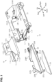
FIG. 1 is an exploded perspective view illustrating a structure of an imaging device for a vehicle according to a first embodiment. -
FIG. 2 is a perspective view of the imaging device for a vehicle illustrated inFIG. 1 in an assembled state. -
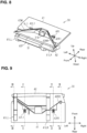
FIG. 3 is a plan view of the imaging device for a vehicle illustrated inFIG. 2 from a perspective facing a rear surface of a bracket body. -
FIG. 4 is an end surface view along line IV-IV ofFIG. 3 . -
FIG. 5 is an end surface view along line V-V ofFIG. 3 . -
FIG. 6 is an end surface view along line VI-VI ofFIG. 3 . -
FIG. 7 is an exploded perspective view illustrating a structure of an imaging device for a vehicle according to a second embodiment. -
FIG. 8 is a perspective view of the imaging device for a vehicle illustrated inFIG. 7 in an assembled state. -
FIG. 9 is a plan view of the imaging device for a vehicle illustrated inFIG. 8 from a perspective facing a rear surface of a bracket body. -
FIG. 10 is an end surface view along line X-X ofFIG. 9 . -
FIG. 11 is an end surface view along line XI-XI ofFIG. 9 . -
FIG. 12 is an end surface view along line XII-XII ofFIG. 9 . -
FIG. 13 is an end surface view along line XIII-XIII ofFIG. 9 . - A first embodiment of an imaging device for a mounting device will be described with reference to
FIG. 1 through FIG. 6 . - An imaging device for a
vehicle 10 illustrated inFIG. 1 is mounted on an attachment subject and receives light incident through the attachment subject. The attachment subject is a surface of a transparent member that is optically transparent and transmits visible light, and is, for example, a surface inside a vehicle cabin on a window glass for a vehicle. The imaging device for avehicle 10 is mounted on a surface of a pair of surfaces of the window glass included inside a vehicle cabin. The window glass is, for example, a windshield glass, but may also be a sunroof glass, a rear glass, or the like. The imaging device for avehicle 10 includes acamera unit 11 and a mountingdevice 12. - The
camera unit 11 includes a camera body 11A, and alens 11B, which is one example of a light receiving unit. The camera body 11A includes, for example, an imaging element, a recording element, and a housing, and the like, in which these elements are housed. Thelens 11B is exposed outside the camera body 11A and receives light incident through the attachment subject. - The mounting
device 12 is a device for mounting thecamera unit 11 to the attachment subject. The mountingdevice 12 includes abracket 21 and alens hood 22. Thebracket 21 supports thecamera unit 11 that includes thelens 11B. Thebracket 21 is mounted on the attachment subject while supporting thecamera unit 11. Thelens hood 22 includes asurface 22F that expands in a direction away from thelens 11B in front of thelens 11B. Thelens hood 22 is mounted on thebracket 21 so that thesurface 22F faces the attachment subject. Thelens hood 22 can be removed from thebracket 21 along the attachment subject while thecamera unit 11 is being supported by thebracket 21. - Because the
lens hood 22 can be removed along the attachment subject from thebracket 21 supporting thecamera unit 11, thelens hood 22 can be removed without removing thecamera unit 11 or the entire mountingdevice 12. Therefore, thelens hood 22 can be removed easily. - Furthermore, the
lens hood 22 can, while thecamera unit 11 is mounted on thebracket 21, be mounted on thebracket 21 along a direction opposite a direction in which thelens hood 22 is removed. Therefore, because thelens hood 22 can be mounted along the attachment subject to thebracket 21 supporting thecamera unit 11, mounting thelens hood 22 does not require removal of thecamera unit 11 or the entire mountingdevice 12. Therefore, thelens hood 22 can be mounted easily. - Each member included in the imaging device for a
vehicle 10 is described in detail below with reference toFIG. 1 . - The camera body 11A included in the
camera unit 11 has an outer shape in which a substantially L-shaped cross-sectional shape is continuous along a left-right direction of the imaging device for avehicle 10. Thecamera unit 11 includes a first right engaging part 11R1, a second right engaging part 11R2, a first left engaging part 11L1, and a second left engaging part 11L2. A pair of the right engaging parts 11R1 and 11R2 has a columnar shape protruding in the left-right direction from a right side surface of the camera body 11A. A pair of the left engaging parts 11L1 and 11L2 has a columnar shape protruding in the left-right direction from a left side surface of the camera body 11A. A pair of the first engaging parts 11R1 and 11L1 extends along the same central axis. A pair of the second engaging parts 11R2 and 11L2 extends along the same central axis in a different position than the pair of first engaging parts 11R1 and 11L1. The pair of second engaging parts 11R2 and 11L2 is positioned in front of the pair of first engaging parts 11R1 and 11L1. - The
bracket 21 is mounted on the attachment subject by a mounting member such as an adhesive member, a fastening member, or the like. Thebracket 21 is a resin molded product formed using synthetic resin. Thebracket 21 includes a right engaging leg 21LR and a left engaging leg 21LL. A pair of the engaging legs 21LR and 21LL is aligned in the left-right direction in thebracket 21 with a gap therebetween. Each of the engaging legs 21LR and 21LL is shaped extending along a front-rear direction. - The right engaging leg 21LR includes a first right engaging groove LR1 and a second right engaging groove LR2. The left engaging leg 21LL includes a first left engaging groove LL1 and a second left engaging groove LL2. A pair of the first engaging grooves LR1 and LL1 is positioned on the same axis extending in the left-right direction. A pair of the second engaging grooves LR2 and LL2 is positioned on the same axis extending in the left-right direction. The pair of second engaging grooves LR2 and LL2 is positioned in front the pair of first engaging grooves LR1 and LL1.
- When the imaging device for a
vehicle 10 is assembled, the first right engaging part 11R1 is fitted into the first right engaging groove LR1, and the first left engaging part 11L1 is fitted into the first left engaging groove LL1. Furthermore, the second right engaging part 11R2 is fitted into the second right engaging groove LR2, and the second left engaging part 11L2 is fitted into the second left engaging groove LL2. This results in thebracket 21 supporting thecamera unit 11. - The
bracket 21 includes a right engaging hole 21HR that passes through the right engaging leg 21LR. The right engaging hole 21HR is positioned midway along the front-rear direction in the right engaging leg 21LR. The right engaging hole 21HR is positioned above the first right engaging groove LR1 and the second right engaging groove LR2, which are on the right engaging leg 21LR. - The
bracket 21 also includes a left engaging piece 21PL and a left guiding strip 21BL. The left engaging piece 21PL is positioned on, of a pair of sides extending in the left-right direction on thebracket 21, the rearward of these sides. The left engaging piece 21PL and the left guiding strip 21BL are positioned above the first left engaging groove LL1 and the second engaging groove LL2, which are on the left engaging leg 21LL. The left guiding strip 21BL is positioned below the left engaging piece 21PL. The left engaging piece 21PL is rectangular extending along the front-rear direction and projects into an opening defined by thebracket 21. In the same way as the left engaging piece 21PL, the left guiding strip 21BL is positioned on, in a pair of sides extending in the left-right direction on thebracket 21, the rearward of these sides. The left guiding strip 21BL extends along the left-right direction from a left end on said side. - Note that the
bracket 21 includes a right leg engaging hole and a left leg engaging hole that are not illustrated in the drawings (seeFIG. 4 ). - In the same way as the
bracket 21 described above, thelens hood 22 is a resin molded product formed using synthetic resin. Thelens hood 22 includes ahood body 22A. Thehood body 22A is substantially trapezoidal and includes asurface 22F. Thesurface 22F is a surface of thelens hood 22 that faces the attachment subject when the imaging device for avehicle 10 is mounted on the attachment subject. Arear surface 22R is a surface on thehood body 22A on a side opposite thesurface 22F. - The
lens hood 22 includes a right wall part 22WR and a left wall part 22WL. The right wall part 22WR is substantially L-shaped along a right diagonal side of and part of an upper base on thehood body 22A. The left wall part 22WL is substantially L-shaped along a left diagonal side of and part of an upper base on thehood body 22A. Thelens 11B of thecamera unit 11 is positioned between the pair of wall parts 22WR and 22WL when thelens hood 22 is supported by thebracket 21. Therefore, thehood body 22A is shaped expanding in front of thelens 11B in a direction away from thelens 11B. - The
lens hood 22 includes a right engaging protrusion 22PR, a left engaging protrusion 22PL, a right engaging leg 22LR, and a left engaging leg 22LL. - The right engaging protrusion 22PR protrudes from the
hood body 22A and is thus shaped so as to extend along the direction in which thelens hood 22 is removed. By engaging with thebracket 21, the right engaging protrusion 22PR engages thehood body 22A to thebracket 21. The right engaging protrusion 22PR is one example of a first engaging part. - The right engaging protrusion 22PR is connected to a rear right end of the
hood body 22A. The right engaging protrusion 22PR is rectangular extending along the left-right direction. When thelens hood 22 mounted on thebracket 21 is removed from thebracket 21, thelens hood 22 is pulled out along the attachment subject and the left-right direction from thebracket 21. Because, at this time, the right engaging protrusion 22PR extends along the direction in which thelens hood 22 is removed, thelens hood 22 can be removed from thebracket 21 by sliding thelens hood 22 along the attachment subject. - The left engaging protrusion 22PL is one example of a second engaging part. The left engaging protrusion 22PL is connected to a rear left end of the
hood body 22A. The left engaging protrusion 22PL is rectangular extending along the front-rear direction and protrudes from thehood body 22A in the front-rear direction. By engaging with thebracket 21, the left engaging protrusion 22PL engages thehood body 22A to thebracket 21. - The left engaging protrusion 22PL extends along a direction that intersects a direction in which the right engaging protrusion 22PR extends. When the
lens hood 22 is mounted on thebracket 21, thelens hood 22 is inserted into thebracket 21 along, in the same way as when removed, the attachment subject and the left-right direction. However, a direction in which thelens hood 22 slides when mounted, and a direction in which thelens hood 22 slides when removed, are oriented opposite one another. That is, the direction in which thelens hood 22 slides when mounted is a direction on thebracket 21 from the left engaging leg 21LL to the right engaging leg 21LR. Conversely, the direction in which thelens hood 22 slides when removed is a direction on thebracket 21 from the right engaging leg 21LR to the left engaging leg 21LL. - Because the
lens hood 22 slides in the direction from the right engaging leg 21LR to the left engaging leg 21LL when thelens hood 22 is mounted on thebracket 21, the left engaging protrusion 22PL is positioned behind the right engaging protrusion 22PR in a direction in which thelens hood 22 is mounted. Thelens hood 22 can be mounted on thebracket 21 by both the right engaging protrusion 22PR and the left engaging protrusion 22PL by mounting thelens hood 22 along the attachment subject. Thus, thelens hood 22 can be mounted on thebracket 21 more securely than in a case where thelens hood 22 is mounted on thebracket 21 by one engaging part. - The right engaging leg 22LR is connected to the
rear surface 22R of thehood body 22A. The right engaging leg 22LR protrudes along an up-down direction from a front side on thehood body 22A. The right engaging leg 22LR is substantially L-shaped in a cross section along a surface prescribed by the left-right direction and the up-down direction, and the L-shaped cross section has a shape that continues along the front-rear direction. - The left engaging leg 22LL is connected to the
rear surface 22R of thehood body 22A. The left engaging leg 22LL protrudes along the up-down direction from a front left end on thehood body 22A. The left engaging leg 22LL is substantially L-shaped in a cross section along a surface prescribed by the left-right direction and the up-down direction, and the L-shaped cross section has a shape that continues along the front-rear direction. - When the imaging device for a
vehicle 10 is assembled, the right engaging leg 22LR is fitted into the right leg engaging hole (seeFIG. 4 ) described above, and the left engaging leg 22LL is fitted into the left leg engaging hole described above. This results in thelens hood 22 being supported by thebracket 21. - The mounting
device 12 includes aheating unit 23. Theheating unit 23 is substantially trapezoidal. A width of theheating unit 23 in the left-right direction is about the same as a width of thehood body 22A. A width of theheating unit 23 in the front-rear direction is about the same as a width of thehood body 22A. An area to be heated by theheating unit 23 is about the same shape and size as an external form of theheating unit 23. - The
heating unit 23 may be, for example, a planar heating element. Theheating unit 23 includes, for example, a planar good conductor, a current-carrying unit, and a pair of insulating films. The current-carrying unit is formed of a single heating wire and is connected to a supplying unit not illustrated in the drawings. The current-carrying unit is sandwiched between the pair of insulating films. The planar good conductor is affixed on one of the insulating films. The supplying unit is electrically connected to theheating unit 23 and supplies electric current to theheating unit 23. Theheating unit 23 is affixed to therear surface 22R of thehood body 22A by an adhesive, a glue, and the like. -
FIG. 2 illustrates the imaging device for avehicle 10 in an assembled state. - When the imaging device for a
vehicle 10 illustrated inFIG. 2 is assembled, thecamera unit 11 is first mounted on the pair of engaging legs 21LR and 21LL included on thebracket 21. Next, sliding thelens hood 22 along the left-right direction slides the left engaging protrusion 22PL along the left guiding strip 21BL of thebracket 21 while inserting the right engaging protrusion 22PR of thelens hood 22 into the right engaging hole 21HR of thebracket 21. At this time, the right engaging leg 22LR of thelens hood 22 is fitted into the right leg engaging hole (seeFIG. 4 ) of thebracket 21, and the left engaging leg 22LL of thelens hood 22 is fitted into the left leg engaging hole (seeFIG. 4 ) of thebracket 21. This makes it possible to mount thelens hood 22 to thebracket 21. - As is illustrated in
FIG. 2 , with the imaging device for avehicle 10 according to the present embodiment, a gap G in the front-rear direction between the camera body 11A that supports thelens 11B and thelens hood 22 is larger than an amount by which thelens 11B protrudes from the camera body 11A. Therefore, thecamera unit 11 does not interfere with sliding of thelens hood 22 when thecamera unit 11 is mounted on thebracket 21. That is, thecamera unit 11 does not hinder the sliding of thelens hood 22. Therefore, thelens hood 22 can be mounted on thebracket 21 to which thecamera unit 11 has been mounted. - Note that when the
lens hood 22 is mounted on thebracket 21 for the first time, thecamera unit 11 is mounted on thebracket 21, thebracket 21 supporting thecamera unit 11 is mounted on the attachment subject, and then, thelens hood 22 is mounted on thebracket 21. Or, thecamera unit 11 and thelens hood 22 may be mounted on thebracket 21 in that order, and then, thebracket 21 may be mounted on the attachment subject. In either case, thelens hood 22 can be mounted on thebracket 21 while thecamera unit 11 is mounted on thebracket 21. - Meanwhile, the
lens hood 22 can also be removed from thebracket 21 mounted on the attachment subject. Because, as is described above, thecamera unit 11 does not hinder the sliding of thelens hood 22, thelens hood 22 can be removed from thebracket 21 while thecamera unit 11 is mounted on thebracket 21. Because thesurface 22F of thelens hood 22 faces the attachment subject while the imaging device for avehicle 10 is mounted on the attachment subject, thelens hood 22 can be removed along the attachment subject by sliding thelens hood 22 along the left-right direction. For example, thelens hood 22 removed from thebracket 21 for maintenance, or the like, can be remounted on thebracket 21 mounted on the attachment subject. - As is described above, all of the engaging grooves LR1, LR2, LL1, and LL2 for supporting the
camera unit 11 in thebracket 21 are positioned below the right engaging hole 21HR, the left engaging piece 21PL, and the left guiding strip 21BL for supporting thelens hood 22. Therefore, thebracket 21 supports part of thecamera unit 11 on a side opposite the attachment subject with respect to thelens hood 22 while thecamera unit 11 and thelens hood 22 are mounted on thebracket 21. Because, as is described above, thelens hood 22 can be removed along the attachment subject, thelens hood 22 can be removed from thebracket 21, even if part of thecamera unit 11 is positioned on a side opposite the attachment subject with respect to thelens hood 22. -
FIG. 3 illustrates a planar structure of the imaging device for avehicle 10 as seen from a viewpoint facing therear surface 22R of thelens hood 22. Note that inFIG. 3 through FIG. 6 , which will be referenced below, the left-right direction is reversed from that inFIG. 1 andFIG. 2 for the convenience of illustration. Also, illustration of thecamera unit 11 is omitted inFIG. 3 through FIG. 6 for the convenience of illustration.FIG. 4 illustrates an end surface structure along line IV-IV illustrated inFIG. 3 .FIG. 5 illustrates an end surface structure along line V-V illustrated inFIG. 3 .FIG. 6 illustrates an end surface structure along line VI-VI illustrated inFIG. 3 . - As is illustrated in
FIG. 3 , with the imaging device for avehicle 10, the right engaging protrusion 22PR, the left engaging protrusion 22PL, the right engaging leg 22LR, and the left engaging leg 22LL included on thelens hood 22 are all supported by thebracket 21. This results in thelens hood 22 being supported by thebracket 21. The structure where the right engaging protrusion 22PR, the left engaging protrusion 22PL, the right engaging leg 22LR, and the left engaging leg 22LL are all supported by thebracket 21 is described in greater detail below with reference toFIG. 4 to FIG. 6 . -
FIG. 4 illustrates a structure where the right engaging leg 22LR and the left engaging leg 22LL of thelens hood 22 are supported by thebracket 21. - As is illustrated in
FIG. 4 , thebracket 21 includes a right leg engaging hole HLR and a left leg engaging hole HLL that pass through thebracket 21 in the left-right direction. When thelens hood 22 is mounted on thebracket 21, the right engaging leg 22LR is fitted into the right leg engaging hole HLR and the left engaging leg 22LL is fitted into the left leg engaging hole HLL. - The left engaging leg 22LL fits into the left leg locking hold HLL so as to be able to slide in the left-right direction with respect to the left leg engaging hole HLL. Therefore, the left engaging leg 22LL can be removed from the left leg engaging hole HLL simply by sliding the
lens hood 22 in the left-right direction. - Meanwhile, after the right engaging leg 22LR has been fitted into the right leg engaging hole HLR, the right engaging leg 22LR is restricted from sliding in the left-right direction by the
bracket 21. However, the slide restriction by thebracket 21 can be released by pushing up from below on a portion of the right engaging leg 22LR that has passed through the right leg engaging hole HLR. The right engaging leg 22LR can be removed from the right leg engaging hole HLR by pushing up on the portion of the right engaging leg 22LR that has passed through the right leg engaging hole HLR and sliding thelens hood 22 in the left-right direction while maintaining an upward pushing state. -
FIG. 5 illustrates a structure where the right engaging protrusion 22PR of thelens hood 22 is supported by thebracket 21. - As is illustrated in
FIG. 5 , the right engaging protrusion 22PR is fitted into the right engaging hole 21HR while thelens hood 22 is mounted on thebracket 21. The right engaging protrusion 22PR is thus restricted from sliding in the left-right direction by thebracket 21. However, the slide restriction by thebracket 21 can be released by pushing up from below on a portion of the right engaging protrusion 22PR that has passed through the right engaging hole 21HR. The right engaging protrusion 22PR can be removed from the right engaging hole 21HR by sliding thelens hood 22 in the left-right direction while maintaining a state of pushing upward on the portion of the right engaging protrusion 22PR that has passed through the right engaging hole 21HR. - Note that, to remove the
lens hood 22 from thebracket 21, the slide restriction on the right engaging leg 22LR and the slide restriction on the right engaging protrusion 22PR must be released simultaneously. -
FIG. 6 illustrates a structure where the left engaging protrusion 22PL of thelens hood 22 is supported by thebracket 21. - As is illustrated in
FIG. 6 , when thelens hood 22 is mounted on thebracket 21, the left engaging protrusion 22PL is sandwiched between the left engaging piece 21PL and the left guiding strip 21BL in the up-down direction. Because the left engaging protrusion 22PL is sandwiched between the left engaging piece 21PL and the left guiding strip 21BL in a state where the left engaging protrusion 22PL can be slid in the left-right direction, the left engaging protrusion 22PL can be moved to the left of the left engaging piece 21PL just by sliding thelens hood 22 in the left-right direction. - The effects disclosed below can be obtained according to the first embodiment of the imaging device mounting device as described above.
- (1) Because the
lens hood 22 can be removed along the attachment subject from thebracket 21 supporting thecamera unit 11, thelens hood 22 can be removed without removing thecamera unit 11 or the entire mountingdevice 12. Therefore, thelens hood 22 can be removed easily. - (2) Because the
lens hood 22 can be mounted along the attachment subject to thebracket 21 supporting thecamera unit 11, mounting thelens hood 22 does not require removal of thecamera unit 11 or the entire mountingdevice 12. Therefore, thelens hood 22 can be mounted easily. - (3) Because the right engaging protrusion 22PR extends along the direction in which the
lens hood 22 is removed, thelens hood 22 can be removed from thebracket 21 by sliding thelens hood 22 along the attachment subject. - (4) The
lens hood 22 can be mounted on thebracket 21 by both the right engaging protrusion 22PR and the left engaging protrusion 22PL. Thus, thelens hood 22 can be mounted on thebracket 21 more securely than in a case where thelens hood 22 is mounted on thebracket 21 by one engaging part. - (5) Because the
lens hood 22 can be removed along the attachment subject, thelens hood 22 can be removed from thebracket 21, even if part of thecamera unit 11 is positioned on a side opposite the attachment subject with respect to thelens hood 22. - A second embodiment of the imaging device mounting device will be described with reference to
FIG. 7 through FIG. 13 . In the second embodiment, a lens hood is slid in a different direction with respect to a bracket than in the first embodiment described above. Therefore, points that differ from the first embodiment will be described in particular detail below. - In the same way as the imaging device for a
vehicle 10 according to the first embodiment, an imaging device for avehicle 30 illustrated inFIG. 7 is mounted on an attachment subject and receives light incident through the attachment subject. The attachment subject is a transparent member that is optically transparent and transmits visible light, and is, for example, a window glass for a vehicle. The imaging device for avehicle 10 is mounted on a surface, in a pair of surfaces the window glass includes, inside a vehicle cabin. The window glass is, for example, a windshield glass, but may also be a sunroof glass, a rear glass, or the like. The imaging device for avehicle 30 includes acamera unit 31 and a mountingdevice 32. - The
camera unit 31 includes acamera body 31A and alens 31B, which is one example of a light receiving unit. Thecamera body 31A includes, for example, an imaging element, a recording element, a housing, and the like, in which these elements are housed. Thelens 31B is exposed outside thecamera body 31A and receives light incident through the attachment subject. - The mounting
device 32 is a device for mounting thecamera unit 31 to the attachment subject. The mountingdevice 32 includes abracket 41 and alens hood 42. Thebracket 41 supports thecamera unit 31 that includes thelens 31B. Thebracket 41 is mounted on the attachment subject while supporting thecamera unit 31. Thelens hood 42 includes asurface 42F that expands in a direction away from thelens 31B in front of thelens 31B. Thelens hood 42 is mounted on thebracket 41 so that thesurface 42F faces the attachment subject. Thelens hood 42 can be removed from thebracket 41 along the attachment subject while thecamera unit 31 is being supported by thebracket 41. - Because the
lens hood 42 can be removed along the attachment subject from thebracket 41 supporting thecamera unit 31, thelens hood 42 can be removed without removing thecamera unit 31 or the entire mountingdevice 32. Therefore, thelens hood 42 can be removed easily. - Furthermore, the
lens hood 42 can, while thecamera unit 31 is mounted on thebracket 41, be mounted on thebracket 41 along a direction opposite a direction in which thelens hood 42 is removed. Therefore, because thelens hood 42 can be mounted along the attachment subject to thebracket 41 supporting thecamera unit 31, mounting thelens hood 42 does not require removal of thecamera unit 31 or the entire mountingdevice 32. Therefore, thelens hood 42 can be mounted easily. - Each member included in the imaging device for a
vehicle 30 is described in detail below with reference toFIG. 7 . - The
camera body 31A included in thecamera unit 31 has an outer shape in which a substantially L-shaped cross-sectional shape is continuous along a left-right direction of the imaging device for avehicle 30. Thecamera unit 31 includes a first right engaging part 31R1, a second right engaging part 31R2, a first left engaging part not illustrated in the drawings, and a second left engaging part not illustrated in the drawings. A pair of the right engaging parts 31R1 and 31R2 has a columnar shape protruding in the left-right direction from a right side surface of thecamera body 31A. A pair of the left engaging parts has a columnar shape protruding in the left-right direction from a left side surface of thecamera body 31A. A pair of the first engaging parts extends along the same central axis. A pair of the second engaging parts extends along the same central axis in a different position than the pair of first engaging parts. The pair of second engaging parts is positioned in front of the pair of first engaging parts. - The
bracket 41 is mounted on the attachment subject by a mounting member such as an adhesive member, a fastening member, or the like. Thebracket 41 is a resin molded product formed using synthetic resin. Thebracket 41 includes a substantially rectangular plate-shapedbracket body 41A. Thebracket body 41A includes asurface 41F, and arear surface 41R on a side opposite thesurface 41F. When the imaging device for avehicle 30 is mounted on the attachment subject, thesurface 41F of thebracket body 41A is positioned along the attachment subject. Thebracket body 41A includes a substantially V-shapedcutout 41C on a front edge extending along the left-right direction. - The
bracket 41 includes a right engaging leg 41LR and a left engaging leg 41LL. Each of the engaging legs 41LR and 41LL is connected to therear surface 41R of thebracket body 41A. Each of the engaging legs 41LR and 41LL is shaped extending along the front-rear direction, and part of each of the engaging legs 41LR and 41LL is exposed in thecutout 41C. - The right engaging leg 41LR includes a first right engaging groove and a second right engaging groove that are not illustrated in the drawings. The left engaging leg 21LL includes a first left engaging groove LL1 and a second left engaging groove LL2. A pair of the first engaging grooves is positioned on the same axis extending in the left-right direction. A pair of the second engaging grooves is positioned on the same axis extending in the left-right direction. The pair of second engaging grooves is positioned in front of the pair of first engaging grooves.
- When the imaging device for a
vehicle 30 is assembled, the first right engaging part 31R1 is fitted into the first right engaging groove, and the first left engaging part is fitted into the first left engaging groove LL1. Furthermore, the second right engaging part 31R2 is fitted into the second right engaging groove, and the second left engaging part is fitted into the second left engaging groove LL2. This results in thebracket 41 supporting thecamera unit 31. - The
bracket body 41A includes a first right body groove AR1 and a first left body groove AL1. The first right body groove AR1 is positioned to the right of a center of thecutout 41C. The first right body groove AR1 forms a cavity in thesurface 41F and an opening in thecutout 41C. On a side surface defined by the first right body groove AR1, a hole is formed that passes through thebracket 41 along the front-rear direction. The first left body groove AL1 is positioned to the left of the center of thecutout 41C. The first left body groove AL1 forms a cavity in thesurface 41F and an opening in thecutout 41C. On a side surface defined by the first left body groove AL1, a hole is formed that passes through thebracket 41 along the front-rear direction. - The
bracket body 41A includes a second right body groove AR2 and a second left body groove AL2. The second right body groove AR2 and the second left body groove AL2 are positioned on a side surface of thebracket body 41A. The side surface connects thesurface 41F and therear surface 41R. The second right body groove AR2 is open facing downward on a right end of thecutout 41C. On a side surface defined by the second left body groove AL2, a hole is formed that passes through thebracket 41 along the front-rear direction. The second left body groove AL2 is open facing sideways on a left end of thecutout 41C. - The first right body groove AR1, second right body groove AR2, first left body groove AL1, and second left body groove AL2 are grooves for securing the
lens hood 42 to thebracket 41. The first right body groove AR1, second right body groove AR2, first left body groove AL1, and second left body groove AL2 are positioned above the right engaging leg 41LR and the left engaging leg 41LL. - In the same way as the
bracket 41 described above, thelens hood 42 is a resin molded product formed using synthetic resin. Thelens hood 42 includes ahood body 42A. Thehood body 42A is substantially trapezoidal and includes asurface 42F. Thesurface 42F is a surface of thelens hood 42 that faces the attachment subject when the imaging device for avehicle 30 is mounted on the attachment subject. - The
lens hood 42 includes a right wall part 42WR and a left wall part 42WL. The right wall part 42WR is substantially L-shaped along a right diagonal side of and part of an upper base on thehood body 42A. The left wall part 42WL is substantially L-shaped along a left diagonal side of and part of an upper base on thehood body 42A. Thelens 31B of thecamera unit 31 is positioned between the pair of wall parts 42WR and 42WL when thelens hood 42 is supported by thebracket 41. Therefore, thehood body 42A is shaped expanding in front of thelens 31B in a direction away from thelens 31B. - The
lens hood 42 includes a first right engaging protrusion 42R1, a second right engaging protrusion 42R2, a first left engaging protrusion 42L1, and a second left engaging protrusion 42L2. Each of the engaging protrusions 42R1, 42R2, 42L1, and 42L2 is an example of an engaging part. That is, by engaging with thebracket 41, each of the engaging protrusions 42R1, 42R2, 42L1, and 42L2 locks thehood body 42A to thebracket 41. The first right engaging protrusion 42R1 is connected to a middle of a right diagonal side of thehood body 42A. The first right engaging protrusion 42R1 is rectangular extending along the front-rear direction. The first left engaging protrusion 42L1 is connected to a middle of a left diagonal side of thehood body 42A. The first left engaging protrusion 42L1 is rectangular extending along the front-rear direction. The second right engaging protrusion 42R2 is connected to a right end of thehood body 42A. The second right engaging protrusion 42R2 is substantially rectangular extending along the front-rear direction. The second left engaging protrusion 42L2 is connected to a left end of thehood body 42A. The second left engaging protrusion 42L2 is substantially rectangular extending along the front-rear direction. - When the
lens hood 42 mounted on thebracket 41 is removed from thebracket 21, thelens hood 42 is pulled out along the attachment subject and the front-rear direction. Thus, because each of the engaging protrusions 42R1, 42R2, 42L1, and 42L2 extends along the direction in which thelens hood 42 is removed, thelens hood 42 can be removed from thebracket 41 by sliding thelens hood 42 along the attachment subject. - A mounting
device 42 includes aheating unit 43. Theheating unit 43 is substantially trapezoidal. A width of theheating unit 43 in the left-right direction is about the same as a width of thehood body 42A. A width of theheating unit 43 in the front-rear direction is about the same as a width of thehood body 42A. An area to be heated by theheating unit 43 is about the same shape and size as an external form of theheating unit 43. - The
heating unit 43 may be, for example, a planar heating element. Theheating unit 43 includes, for example, a planar good conductor, a current-carrying unit, and a pair of insulating films. The current-carrying unit is formed of a single heating wire and is connected to a supplying unit not illustrated in the drawings. The current-carrying unit is sandwiched between the pair of insulating films. The planar good conductor is affixed on one of the insulating films. The supplying unit is electrically connected to theheating unit 43 and supplies electric current to theheating unit 43. Theheating unit 43 is affixed to a rear surface on a side opposite thesurface 42F of thehood body 42A by an adhesive, a glue, and the like. -
FIG. 8 illustrates the imaging device for avehicle 30 in an assembled state. - When the imaging device for a
vehicle 30 illustrated inFIG. 8 is assembled, thecamera unit 31 is first mounted on the pair of engaging legs 41LR and 41LL included on thebracket 41. Next, a pair of the first engaging protrusions 42R1 and 42L1 are inserted into the first body grooves AR1 and AL1 corresponding to each of the first engaging protrusions 42R1 and 42L1 by sliding thelens hood 42 along the front-rear direction. At the same time, a pair of the second engaging protrusions 42R2 and 42L2 is inserted into the second body grooves AR2 and AL2 corresponding to each of the engaging protrusions 42R2 and 42L2. This makes it possible to mount thelens hood 42 to thebracket 41. - With the imaging device for a
vehicle 30 according to the present embodiment, thelens hood 42 is removed from thebracket 41 along the front-rear direction. That is, thelens hood 42 is removed from thebracket 41 by sliding thelens hood 42 further forward than thelens 31B along the front-rear direction. Therefore, thecamera unit 31 does not interfere with sliding of thelens hood 42 when thecamera unit 31 is mounted on thebracket 41. That is, thecamera unit 31 does not hinder the sliding of thelens hood 42. Therefore, thelens hood 42 can be mounted on thebracket 41 to which thecamera unit 31 has been mounted. - Note that, in the same way as the imaging device for a
vehicle 10 according to the first embodiment, when thelens hood 42 is mounted on thebracket 41 for the first time, thecamera unit 31 is mounted on thebracket 41, thebracket 41 supporting thecamera unit 31 is mounted on the attachment subject, and then, thelens hood 42 is mounted on thebracket 41. Or, thecamera unit 31 and thelens hood 42 may be mounted on thebracket 41 in that order, and then, thebracket 41 may be mounted on the attachment subject. In either case, thelens hood 42 can be mounted on thebracket 41 while thecamera unit 31 is mounted on thebracket 41. - Meanwhile, the
lens hood 42 can also be removed from thebracket 41 mounted on the attachment subject. Because, as is described above, thecamera unit 31 does not hinder the sliding of thelens hood 42, thelens hood 42 can be removed from thebracket 41 while thecamera unit 31 is mounted on thebracket 41. Because thesurface 42F of thelens hood 42 faces the attachment subject while the imaging device for avehicle 30 is mounted on the attachment subject, thelens hood 42 can be removed along the attachment subject by sliding thelens hood 42 along the front-rear direction. For example, thelens hood 42 removed from thebracket 41 for maintenance, or the like, can be remounted on thebracket 41 mounted on the attachment subject. - As is described above, each of the pair of engaging legs 41LR and 41LL that includes engaging grooves for supporting the
camera unit 31 in thebracket 41 is positioned below each of the body grooves AR1, AR2, AL1, and AL2 for supporting thelens hood 42. Therefore, thebracket 41 supports part of thecamera unit 31 on a side opposite the attachment subject with respect to thelens hood 42 while thecamera unit 31 and thelens hood 42 are mounted on thebracket 41. Because, as is described above, thelens hood 42 can be removed along the attachment subject, thelens hood 42 can be removed from thebracket 41, even if part of thecamera unit 31 is positioned on a side opposite the attachment subject with respect to thelens hood 42. -
FIG. 9 illustrates a planar structure of the imaging device for avehicle 30 as seen from a viewpoint facing therear surface 41R of thebracket 41. Note that inFIG. 9 through FIG. 13 , which will be referenced below, the front-rear direction is reversed from that inFIG. 7 andFIG. 8 for the convenience of illustration. Also, illustration of thecamera unit 31 is omitted inFIG. 9 through FIG. 13 for the convenience of illustration.FIG. 10 illustrates an end surface structure along line X-X illustrated inFIG. 9 .FIG. 11 illustrates an end surface structure along line XI-XI illustrated inFIG. 9 .FIG. 12 illustrates an end surface structure along line XII-XII illustrated inFIG. 9 .FIG. 13 illustrates an end surface structure along line XIII-XIII illustrated inFIG. 9 . - As is illustrated in
FIG. 9 , with the imaging device for avehicle 30, the engaging protrusions 42R1, 42R2, 42L1, and 42L2 included on thelens hood 42 are supported by thebracket 41. This results in thelens hood 42 being supported by thebracket 41. A structure whereby the each of the engaging protrusions 42R1, 42R2, 42L1, and 42L2 is supported by thebracket 41 is described in detail below with reference toFIG. 10 through FIG. 13 . -
FIG. 10 illustrates a structure where the first left engaging protrusion 42L1 of thelens hood 42 is supported by thebracket 41. - As is illustrated in
FIG. 10 , the first left engaging protrusion 42L1 is fitted into the hole included in the first left body groove AL1 while thelens hood 42 is mounted on thebracket 41. After the first left engaging protrusion 42L1 is fitted into the hole in the first left body groove AL1, sliding of the first left engaging protrusion 42L1 in the front-rear direction is restricted by thebracket 41. However, the slide restriction by thebracket 41 can be released by pushing up from below on a portion of the first left engaging protrusion 42L1 that has passed through the first left body groove AL1. The first left engaging protrusion 42L1 can be removed from the first left body groove AL1 by pushing up on the portion of the first left engaging protrusion 42L1 that has passed through the first left body groove AL1 and sliding thelens hood 42 in the front-rear direction while maintaining an upward pushing state. -
FIG. 11 illustrates a structure where the first right engaging protrusion 42R1 of thelens hood 42 is supported by thebracket 41. - As is illustrated in
FIG. 11 , the first right engaging protrusion 42R1 is fitted into the hole included in the first right body groove AR1 while thelens hood 42 is mounted on thebracket 41. After the first right engaging protrusion 42R1 is fitted into the hole in the first right body groove AR1, sliding of the first right engaging protrusion 42R1 in the front-rear direction is restricted by thebracket 41. However, the slide restriction by thebracket 41 can be released by pushing up from below on a portion of the first right engaging protrusion 42R1 that has passed through the first right body groove AR1. The first right engaging protrusion 42R1 can be removed from the first right body groove AR1 by pushing up on the portion of the first right engaging protrusion 42R1 that has passed through the first right body groove AR1 and sliding thelens hood 42 in the front-rear direction while maintaining an upward pushing state. - Note that, to remove the
lens hood 42 from thebracket 41, the slide restriction on the first right engaging protrusion 42R1 and the slide restriction on the first left engaging protrusion 42L1 must be released simultaneously. -
FIG. 12 illustrates a structure where the second right engaging protrusion 42R2 of thelens hood 42 is supported by thebracket 41. - As is illustrated in
FIG. 12 , the second right engaging protrusion 42R2 is fitted into thebracket body 41A in a state where sliding in the front-rear direction with respect to the hole in the second right body groove AR2 is possible. Therefore, the second right engaging protrusion 42R2 can be removed from the second right body groove AR2 simply by sliding thelens hood 42 in the front-rear direction. -
FIG. 13 illustrates a structure where the second left engaging protrusion 42L2 of thelens hood 42 is supported by thebracket 41. - As is illustrated in
FIG. 13 , while thelens hood 42 is mounted in thebracket 41, the second left engaging protrusion 42L2 is fitted into the second left body groove AL2 in a state slidable in the front-rear direction with respect to the second left body groove AL2. Therefore, the second left engaging protrusion 42L2 can be removed from the second left body groove AL2 simply by sliding thelens hood 42 in the front-rear direction. - The effects like those in (1) through (3) and (5) described above can be obtained according to the second embodiment of the imaging device mounting device as described above.
- Note that each of the embodiments described above may be modified as described below.
- The
heating units surfaces lens hoods devices heating units heating units lens hoods heating units - The
brackets camera units lens hoods brackets camera units lens hoods vehicle 10 according to the first embodiment, and effects like those in (1) through (3) described above can be obtained in the case of the imaging device for avehicle 30 according to the second embodiment. - The
lens hood 22 included on the imaging device for avehicle 10 according to the first embodiment may include an engaging part that extends along the left-right direction, and, conversely, not include an engaging part that extends in a direction that intersects the left-right direction. Effects like those in (1) through (3) and (5) described above can be obtained even in such cases. - The
lens hoods hood lens brackets lens hoods brackets - The
lens hoods brackets lens hoods lens hoods lens hoods brackets lens hoods brackets lens hoods lens hoods lens hoods brackets - Note that when the
lens hoods brackets lens hoods lens hoods brackets lens hoods brackets lens hoods lens hoods brackets
Claims (5)
- An imaging device for a mounting device, comprising:a bracket supporting a camera unit having a light receiving unit, and configured to be mounted on an attachment subject; anda hood having a surface expanding in a direction away from the light receiving unit in front of the light receiving unit, and mounted on the bracket so that the surface faces the attachment subject,wherein the hood can be removed from the bracket along the attachment subject while the camera unit is being supported by the bracket.
- An imaging device for a mounting device according to claim 1, wherein the hood can, while the camera unit is mounted on the bracket, be mounted on the bracket along a direction opposite a direction in which the hood is removed from the bracket.
- An imaging device for a mounting device according to claim 1 or 2, wherein the hood further comprises:a hood body having a shape expanding in a direction away from the light receiving unit in front of the light receiving unit; andan engaging part protruding from the hood body and having a shape so as to extend along a direction in which the hood is removed, and locking the hood body to the bracket by engaging with the bracket.
- An imaging device for a mounting device according to any one of claims 1 through 3, wherein the bracket supports part of the camera unit on a side opposite the attachment subject with respect to the hood.
- An imaging device for a mounting device according to claim 2, wherein the hood further comprises:a hood body having a shape expanding in a direction away from the light receiving unit in front of the light receiving unit;a first engaging part protruding from the hood body to have a shape so as to extend along a direction in which the hood is mounted, and locking the hood body to the bracket by engaging with the bracket; anda second engaging part extending in a direction intersecting the first engaging part, positioned behind the first engaging part in a direction in which the hood is mounted, and locking the hood body to the bracket by engaging with the bracket.
Applications Claiming Priority (2)
| Application Number | Priority Date | Filing Date | Title |
|---|---|---|---|
| JP2020125494A JP7344853B2 (en) | 2020-07-22 | 2020-07-22 | Mounting device for imaging device |
| PCT/JP2021/024684 WO2022019066A1 (en) | 2020-07-22 | 2021-06-30 | Imaging-apparatus attachment device |
Publications (2)
| Publication Number | Publication Date |
|---|---|
| EP4186752A1 true EP4186752A1 (en) | 2023-05-31 |
| EP4186752A4 EP4186752A4 (en) | 2024-07-24 |
Family
ID=79729419
Family Applications (1)
| Application Number | Title | Priority Date | Filing Date |
|---|---|---|---|
| EP21846299.2A Pending EP4186752A4 (en) | 2020-07-22 | 2021-06-30 | Imaging-apparatus attachment device |
Country Status (5)
| Country | Link |
|---|---|
| US (1) | US12194929B2 (en) |
| EP (1) | EP4186752A4 (en) |
| JP (1) | JP7344853B2 (en) |
| CN (1) | CN115835981B (en) |
| WO (1) | WO2022019066A1 (en) |
Families Citing this family (1)
| Publication number | Priority date | Publication date | Assignee | Title |
|---|---|---|---|---|
| JP7802296B2 (en) * | 2023-02-01 | 2026-01-20 | 株式会社ニフコ | Vehicle equipment mounting structure |
Family Cites Families (16)
| Publication number | Priority date | Publication date | Assignee | Title |
|---|---|---|---|---|
| WO2013123161A1 (en) * | 2012-02-17 | 2013-08-22 | Magna Electronics, Inc. | Vehicle vision system with light baffling system |
| WO2013019795A1 (en) | 2011-08-02 | 2013-02-07 | Magna Electronics Inc. | Vehicular camera system |
| JP5761100B2 (en) | 2012-03-28 | 2015-08-12 | 株式会社デンソー | Car camera |
| KR101698783B1 (en) * | 2013-12-16 | 2017-01-23 | 엘지전자 주식회사 | Stereo camera and Vehicle including the same |
| US9352692B2 (en) * | 2014-03-10 | 2016-05-31 | Magna Mirrors Of America, Inc. | Vehicle vision system with camera and mirror mount |
| DE102014224860A1 (en) | 2014-12-04 | 2016-06-09 | Conti Temic Microelectronic Gmbh | Lens Hood |
| KR101724300B1 (en) * | 2015-02-04 | 2017-04-07 | 엘지전자 주식회사 | Stereo camera |
| WO2016145431A1 (en) * | 2015-03-12 | 2016-09-15 | Trw Automotive U.S. Llc | Low gloss housing assembly for a driver assist system camera |
| CN106476714A (en) * | 2015-08-27 | 2017-03-08 | 日本电产艾莱希斯株式会社 | Vehicle-mounted camera and the manufacture method of vehicle-mounted camera |
| JP6494569B2 (en) | 2016-07-20 | 2019-04-03 | 株式会社ニフコ | Camera unit |
| JP6939353B2 (en) | 2017-09-29 | 2021-09-22 | 株式会社デンソー | In-vehicle camera device |
| JP7025234B2 (en) * | 2018-02-13 | 2022-02-24 | 株式会社Subaru | Out-of-vehicle monitoring device |
| US10863063B2 (en) | 2018-06-20 | 2020-12-08 | Trw Automotive U.S. Llc | Driver assist system |
| JP6726265B2 (en) | 2018-12-18 | 2020-07-22 | 本田技研工業株式会社 | Sensor bracket |
| JP7042206B2 (en) | 2018-12-18 | 2022-03-25 | 本田技研工業株式会社 | Transport equipment and sensor brackets |
| JP7147613B2 (en) | 2019-02-14 | 2022-10-05 | トヨタ自動車株式会社 | Camera mounting structure |
-
2020
- 2020-07-22 JP JP2020125494A patent/JP7344853B2/en active Active
-
2021
- 2021-06-30 EP EP21846299.2A patent/EP4186752A4/en active Pending
- 2021-06-30 CN CN202180048492.XA patent/CN115835981B/en active Active
- 2021-06-30 US US18/016,967 patent/US12194929B2/en active Active
- 2021-06-30 WO PCT/JP2021/024684 patent/WO2022019066A1/en not_active Ceased
Also Published As
| Publication number | Publication date |
|---|---|
| CN115835981B (en) | 2025-11-28 |
| CN115835981A (en) | 2023-03-21 |
| EP4186752A4 (en) | 2024-07-24 |
| WO2022019066A1 (en) | 2022-01-27 |
| US20230280636A1 (en) | 2023-09-07 |
| JP2022021723A (en) | 2022-02-03 |
| JP7344853B2 (en) | 2023-09-14 |
| US12194929B2 (en) | 2025-01-14 |
Similar Documents
| Publication | Publication Date | Title |
|---|---|---|
| EP1411598B1 (en) | A connector assembly, connector, connector assembling construction and method of assembling them | |
| CN108602468B (en) | Apparatus for mounting a camera device on a motor vehicle | |
| US12391181B2 (en) | Base assembly with camera, cleaning system, base frame and base cover, rear view device, vehicle and assembling and dis-assembling method | |
| CN104736392B (en) | display mirror assembly | |
| US20210162932A1 (en) | Module and Support Structure Assembly | |
| EP2112724A1 (en) | Mountable connector assemblies and frames | |
| US7575269B2 (en) | Connector connecting construction, a clamping member and a method of mounting a connector connecting construction | |
| CN109328153B (en) | camera unit | |
| JP2001122003A (en) | Electrical connection structure between seat and body and method thereof | |
| JPH09298808A (en) | Switch box mounting structure | |
| US20210031689A1 (en) | Exterior rearview mirror or winglet for a vehicle having a lighting lens assembly attached to a housing | |
| EP1096617A1 (en) | A connector mounting construction, a connector and a holder therefor | |
| CN120245866A (en) | Display mirror assembly | |
| EP2244346A2 (en) | Flat Panel Display Device | |
| DE102023212939A1 (en) | SYSTEM FOR MONITORING A DRIVER OF A VEHICLE | |
| US12194929B2 (en) | Imaging device for mounting device | |
| US6238242B1 (en) | Panel-mount connector | |
| CN108111719A (en) | For the camera system and assemble method of motor vehicles | |
| JP6650118B2 (en) | Occupant monitoring device | |
| CA2824054C (en) | Systems and methods for installing motorized window shade mechanism in aircraft | |
| FR2849543A1 (en) | LAMP UNIT SWITCH STRUCTURE | |
| US20080302644A1 (en) | Electrical interface shield and method | |
| US20170002835A1 (en) | Fan module | |
| US20250115193A1 (en) | Attachment structure of onboard stereo camera unit | |
| US6095831A (en) | Electrical connector mating structure |
Legal Events
| Date | Code | Title | Description |
|---|---|---|---|
| STAA | Information on the status of an ep patent application or granted ep patent |
Free format text: STATUS: THE INTERNATIONAL PUBLICATION HAS BEEN MADE |
|
| PUAI | Public reference made under article 153(3) epc to a published international application that has entered the european phase |
Free format text: ORIGINAL CODE: 0009012 |
|
| STAA | Information on the status of an ep patent application or granted ep patent |
Free format text: STATUS: REQUEST FOR EXAMINATION WAS MADE |
|
| 17P | Request for examination filed |
Effective date: 20230126 |
|
| AK | Designated contracting states |
Kind code of ref document: A1 Designated state(s): AL AT BE BG CH CY CZ DE DK EE ES FI FR GB GR HR HU IE IS IT LI LT LU LV MC MK MT NL NO PL PT RO RS SE SI SK SM TR |
|
| DAV | Request for validation of the european patent (deleted) | ||
| DAX | Request for extension of the european patent (deleted) | ||
| REG | Reference to a national code |
Ref country code: DE Ref legal event code: R079 Free format text: PREVIOUS MAIN CLASS: B60R0011020000 Ipc: B60R0011040000 |
|
| A4 | Supplementary search report drawn up and despatched |
Effective date: 20240626 |
|
| RIC1 | Information provided on ipc code assigned before grant |
Ipc: H04N 23/51 20230101ALI20240620BHEP Ipc: G03B 30/00 20210101ALI20240620BHEP Ipc: G03B 17/02 20210101ALI20240620BHEP Ipc: G03B 11/04 20210101ALI20240620BHEP Ipc: B60R 11/04 20060101AFI20240620BHEP |
|
| STAA | Information on the status of an ep patent application or granted ep patent |
Free format text: STATUS: EXAMINATION IS IN PROGRESS |
|
| 17Q | First examination report despatched |
Effective date: 20260120 |