EP4186702A1 - Liquid discharge head - Google Patents
Liquid discharge head Download PDFInfo
- Publication number
- EP4186702A1 EP4186702A1 EP22177336.9A EP22177336A EP4186702A1 EP 4186702 A1 EP4186702 A1 EP 4186702A1 EP 22177336 A EP22177336 A EP 22177336A EP 4186702 A1 EP4186702 A1 EP 4186702A1
- Authority
- EP
- European Patent Office
- Prior art keywords
- common
- flow path
- damper
- pressure chamber
- chamber
- Prior art date
- Legal status (The legal status is an assumption and is not a legal conclusion. Google has not performed a legal analysis and makes no representation as to the accuracy of the status listed.)
- Withdrawn
Links
Images




Classifications
-
- B—PERFORMING OPERATIONS; TRANSPORTING
- B41—PRINTING; LINING MACHINES; TYPEWRITERS; STAMPS
- B41J—TYPEWRITERS; SELECTIVE PRINTING MECHANISMS, i.e. MECHANISMS PRINTING OTHERWISE THAN FROM A FORME; CORRECTION OF TYPOGRAPHICAL ERRORS
- B41J2/00—Typewriters or selective printing mechanisms characterised by the printing or marking process for which they are designed
- B41J2/005—Typewriters or selective printing mechanisms characterised by the printing or marking process for which they are designed characterised by bringing liquid or particles selectively into contact with a printing material
- B41J2/01—Ink jet
- B41J2/015—Ink jet characterised by the jet generation process
- B41J2/04—Ink jet characterised by the jet generation process generating single droplets or particles on demand
-
- B—PERFORMING OPERATIONS; TRANSPORTING
- B41—PRINTING; LINING MACHINES; TYPEWRITERS; STAMPS
- B41J—TYPEWRITERS; SELECTIVE PRINTING MECHANISMS, i.e. MECHANISMS PRINTING OTHERWISE THAN FROM A FORME; CORRECTION OF TYPOGRAPHICAL ERRORS
- B41J2/00—Typewriters or selective printing mechanisms characterised by the printing or marking process for which they are designed
- B41J2/005—Typewriters or selective printing mechanisms characterised by the printing or marking process for which they are designed characterised by bringing liquid or particles selectively into contact with a printing material
- B41J2/01—Ink jet
- B41J2/135—Nozzles
- B41J2/14—Structure thereof only for on-demand ink jet heads
- B41J2/14201—Structure of print heads with piezoelectric elements
- B41J2/14209—Structure of print heads with piezoelectric elements of finger type, chamber walls consisting integrally of piezoelectric material
-
- B—PERFORMING OPERATIONS; TRANSPORTING
- B41—PRINTING; LINING MACHINES; TYPEWRITERS; STAMPS
- B41J—TYPEWRITERS; SELECTIVE PRINTING MECHANISMS, i.e. MECHANISMS PRINTING OTHERWISE THAN FROM A FORME; CORRECTION OF TYPOGRAPHICAL ERRORS
- B41J2/00—Typewriters or selective printing mechanisms characterised by the printing or marking process for which they are designed
- B41J2/005—Typewriters or selective printing mechanisms characterised by the printing or marking process for which they are designed characterised by bringing liquid or particles selectively into contact with a printing material
- B41J2/01—Ink jet
- B41J2/135—Nozzles
- B41J2/14—Structure thereof only for on-demand ink jet heads
- B41J2002/14362—Assembling elements of heads
-
- B—PERFORMING OPERATIONS; TRANSPORTING
- B41—PRINTING; LINING MACHINES; TYPEWRITERS; STAMPS
- B41J—TYPEWRITERS; SELECTIVE PRINTING MECHANISMS, i.e. MECHANISMS PRINTING OTHERWISE THAN FROM A FORME; CORRECTION OF TYPOGRAPHICAL ERRORS
- B41J2/00—Typewriters or selective printing mechanisms characterised by the printing or marking process for which they are designed
- B41J2/005—Typewriters or selective printing mechanisms characterised by the printing or marking process for which they are designed characterised by bringing liquid or particles selectively into contact with a printing material
- B41J2/01—Ink jet
- B41J2/135—Nozzles
- B41J2/14—Structure thereof only for on-demand ink jet heads
- B41J2002/14419—Manifold
-
- B—PERFORMING OPERATIONS; TRANSPORTING
- B41—PRINTING; LINING MACHINES; TYPEWRITERS; STAMPS
- B41J—TYPEWRITERS; SELECTIVE PRINTING MECHANISMS, i.e. MECHANISMS PRINTING OTHERWISE THAN FROM A FORME; CORRECTION OF TYPOGRAPHICAL ERRORS
- B41J2202/00—Embodiments of or processes related to ink-jet or thermal heads
- B41J2202/01—Embodiments of or processes related to ink-jet heads
- B41J2202/08—Embodiments of or processes related to ink-jet heads dealing with thermal variations, e.g. cooling
-
- B—PERFORMING OPERATIONS; TRANSPORTING
- B41—PRINTING; LINING MACHINES; TYPEWRITERS; STAMPS
- B41J—TYPEWRITERS; SELECTIVE PRINTING MECHANISMS, i.e. MECHANISMS PRINTING OTHERWISE THAN FROM A FORME; CORRECTION OF TYPOGRAPHICAL ERRORS
- B41J2202/00—Embodiments of or processes related to ink-jet or thermal heads
- B41J2202/01—Embodiments of or processes related to ink-jet heads
- B41J2202/12—Embodiments of or processes related to ink-jet heads with ink circulating through the whole print head
Definitions
- Embodiments described herein relate generally to a liquid discharge head.
- An inkjet head that discharges ink is known as an example of a liquid discharge head used in a liquid discharge device. Further, an inkjet head including a damper for keeping the negative pressure in the common pressure chamber constant at the time of ink discharge is also known. The inkjet head needs to remove air bubbles inside when filling ink. However, such an inkjet head has a problem in that many air bubbles remain in the damper portion. Further, as an inkjet head, a technique is also known in which a rib is provided in a damper chamber to push out air bubbles in the same path as the ink flow. Such an inkjet head needs to include a path communicating with the outside air for discharging air bubbles, which increases the size of the inkjet head.
- a liquid discharge head comprising: a common liquid chamber including an opening; a common pressure chamber connected to the common liquid chamber; an actuator including a plurality of pressure chambers connected to the common pressure chamber; a substrate provided with the actuator and forming the common pressure chamber together with the actuator; a nozzle plate including a plurality of nozzles arranged to face the plurality of pressure chambers, respectively; a damper covering the opening of the common liquid chamber; and a bypass flow path connecting the common liquid chamber and the common pressure chamber.
- the damper is a polyimide film formed to have a thickness of 25 ⁇ m or less.
- the opening of the common liquid chamber covered by the damper has a long shape in one direction, and a width of the damper in a lateral direction is 4 mm or more.
- a fluid resistance of the bypass flow path is smaller than a fluid resistance of the common liquid chamber and the common pressure chamber.
- a flow path cross section of the bypass flow path has a rectangular shape having a width of 1 mm.
- a length of the bypass flow path is 10 mm or more.
- the damper has Young's modulus of 3.4 GPa.
- the head may comprise a manifold unit including a manifold formed in a plate shape or a block shape, the manifold is fixed to a main surface of the substrate, wherein the common liquid chamber is formed in the manifold.
- the manifold may comprise a lower part at a side where the substrate is fixed and an upper part at a side opposite to the side where the substrate is fixed, the upper part forming a ceiling portion of the common liquid chamber.
- the opening may be formed in the upper part and the damper may be fixed around the opening.
- the bypass flow path may be connected to the ceiling portion of the common liquid chamber.
- the bypass flow path may be provided directly below the damper.
- the bypass flow path may be formed into a bent shape in which at least a part of the bypass flow path is bent.
- the manifold unit may further comprise an ink discharge pipe.
- the present invention also relates to a printer comprising the above-described liquid discharge head.
- Embodiments of the present disclosure provide a liquid discharge head capable of removing air bubbles with a simple configuration.
- a liquid discharge head includes a common liquid chamber, a common pressure chamber, an actuator, a substrate, a nozzle plate, a damper, and a bypass flow path.
- the common liquid chamber includes an opening.
- the common pressure chamber is connected to the common liquid chamber.
- the actuator includes a plurality of pressure chambers connected to the common pressure chamber.
- the substrate is provided with the actuator and forms the common pressure chamber together with the actuator.
- the nozzle plate includes a plurality of nozzles arranged in the plurality of pressure chambers, respectively.
- the damper covers the opening of the common liquid chamber.
- the bypass flow path connects the common liquid chamber and the common pressure chamber.
- FIG. 1 is a perspective view showing a configuration of the liquid discharge head 1 according to the embodiment.
- FIG. 2 is a perspective view showing a configuration of a head main body 11 and a manifold unit 12 of the liquid discharge head 1 and
- FIG. 3 is a plan view showing the configuration of the head main body 11 with a nozzle plate 114 omitted.
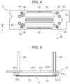
- FIG. 4 is a plan view showing the configuration of the manifold unit 12.
- FIG. 5 is a cross-sectional view showing the configuration of the head main body 11 and the manifold unit 12 in a cross section taken along line V-V in FIG. 4
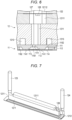
- FIG. 6 is a cross-sectional view showing the configuration of the head main body 11 and the manifold unit 12.
- FIG. 7 is a perspective view showing a part of the flow path configuration of the head main body 11 and the manifold unit 12
- FIG. 8 is a plan view showing a part of the flow path configuration of the head main body 11 and the manifold unit 12.
- FIGS. 9 and 10 are side views showing a part of the flow path configuration of the head main body 11 and the manifold unit 12, and FIGS. 9 and 10 are shown from different directions.
- FIGS. 9 and 10 are side views showing a part of the flow path configuration of the head main body 11 and the manifold unit 12, and FIGS. 9 and 10 are shown from different directions.
- FIGS. 9 and 10 are side views showing a part of the flow path configuration of the head main body 11 and
- FIGS. 11 to 16 are explanatory diagrams showing changes in the pressure of the common pressure chamber due to differences in the shape of a damper 127
- FIGS. 17 and 18 are explanatory diagrams showing the relationship between the shape of the damper 127 and the strain area.
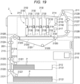
- FIG. 19 is an explanatory diagram showing the configuration of the liquid discharge device 2. For the sake of explanation in each drawing, the configuration is shown enlarged, reduced, or omitted as appropriate.
- the liquid discharge head 1 is, for example, an inkjet head provided in the liquid discharge device 2 such as an inkjet recording device shown in FIG. 19 .
- the liquid discharge head 1 is provided in a head unit 2130 including a supply tank 2132 as a liquid accommodating unit provided in the liquid discharge device 2.
- the liquid discharge head 1 is supplied with ink as a liquid stored in the supply tank 2132.
- the liquid discharge head 1 may be a non-circulation type head that does not circulate ink, or may be a circulation type head that circulates ink. In the present embodiment, the liquid discharge head 1 will be described with reference to an example of a non-circulation type head. Further, the liquid discharge head 1 is connected to a temperature control device 2116 provided in the liquid discharge device 2, and a temperature control liquid (temperature control water) for controlling the temperature of the ink is supplied.
- a temperature control liquid temperature control water
- the liquid discharge head 1 includes the head main body 11, the manifold unit 12, a circuit board 13, and a cover 14.
- the liquid discharge head 1 is a side shooter type four-row integrated structure head including two sets of head main bodies 11 having a pair of actuators 113.
- the head main body 11 discharges the liquid.
- the head main body 11 includes a substrate 111, a frame 112, an actuator 113, and a nozzle plate 114. Further, the head main body 11 includes a common pressure chamber 116. In the example of the present embodiment, an example in which one head main body 11 has two actuators 113 will be described.
- the substrate 111 is formed in a rectangular plate shape by, for example, a ceramic material.
- the substrate 111 is formed, for example, in a rectangular shape that is long in one direction.
- the substrate 111 includes a single or a plurality of supply ports 1111 and a single or a plurality of discharge ports 1112.
- the substrate 111 is provided with a pair of actuators 113 and has a wiring pattern for driving the actuators 113 formed thereon.
- the supply port 1111 and the discharge port 1112 are through-holes penetrating between both main surfaces of the substrate 111.
- a single supply port 1111 is provided, for example, at a position facing a first common pressure chamber 1161 described later in the common pressure chamber 116.
- the supply port 1111 is, for example, an elongated hole long in one direction along the longitudinal direction of the first common pressure chamber 1161.
- Two discharge ports 1112 are provided, for example, at positions facing one of the third common pressure chambers 1163 of the two third common pressure chambers 1163 described later in the common pressure chamber 116. Further, for example, the discharge port 1112 is provided on the substrate 111 adjacent to one end portion in the longitudinal direction of the pair of actuators 113.
- the frame 112 is fixed to one main surface of the substrate 111 with an adhesive or the like.
- the frame 112 surrounds the supply port 1111, the plurality of discharge ports 1112, and the actuators 113, which are provided on the substrate 111.
- the frame 112 is formed in a rectangular frame shape to form a long opening in one direction along the longitudinal direction of the frame 112.
- a pair of actuators 113, the supply port 1111, and two discharge ports 1112 are arranged in the opening of the frame 112.
- the pair of actuators 113 adhere to the mounting surface of the substrate 111.
- the pair of actuators 113 are provided on the substrate 111 side by side in two rows with the supply port 1111 interposed therebetween.
- the actuator 113 is formed in the shape of a long plate in one direction.
- the actuator 113 is disposed in the opening of the frame 112 and adhered to the main surface of the substrate 111.
- the actuator 113 is formed by adhering two pieces of piezoelectric materials having a rectangular plate shape long in one direction to face each other so that their polarization directions are opposite to each other.
- the piezoelectric material is, for example, PZT (lead zirconate titanate).
- the actuator 113 is adhered to the mounting surface of the substrate 111 with, for example, a thermosetting epoxy adhesive.
- the actuator 113 has, for example, a plurality of pressure chambers 1131 arranged at equal intervals in the longitudinal direction.
- the actuator 113 has a plurality of grooves formed in the longitudinal direction of the actuator 113 on the main surface side opposite to the substrate 111 side, and the pressure chamber 1131 is formed by these grooves.
- the actuator 113 has a plurality of walls that are evenly spaced in the longitudinal direction to form grooves therebetween.
- the plurality of walls 1133 form a plurality of pressure chambers 1131 between adjacent walls.
- the wall 1133 is a piezoelectric body as a driving element that changes the volume of the pressure chamber 1131 by applying a drive voltage.
- the surface of the actuator 113 opposite to the substrate 111 adheres to the nozzle plate 114. Further, the actuator 113 is formed with a wiring pattern for driving the plurality of pressure chambers 1131.
- the pressure chamber 1131 is a pressure chamber for injecting ink from the nozzle 1141 during operations such as printing by the liquid discharge head 1.
- the actuator 113 may have a configuration having air chambers alternately arranged with the plurality of pressure chambers 1131. If the air chamber adjacent to the pressure chamber 1131 is provided, the nozzle 1141 is disposed in the portion of the nozzle plate 114 facing the pressure chamber 1131, and the nozzle 1141 is not disposed in the portion facing the air chamber. That is, ink is not discharged from the air chamber.
- the air chamber is closed, for example, by a wall formed of a photosensitive resin at both ends of the groove of the actuator 113.
- the air chamber is formed by closing the groove of the actuator 113 with the substrate 111, the nozzle plate 114, and the walls at both ends.
- the nozzle plate 114 is formed in a plate shape.
- the nozzle plate 114 is fixed to the main surface of the frame 112 on the opposite side of the substrate 111 with an adhesive or the like.
- the nozzle plate 114 includes a plurality of nozzles 1141 formed at positions facing the plurality of pressure chambers 1131.
- the nozzle plate 114 has two rows of nozzles in which the plurality of nozzles 1141 are arranged in one direction.
- the plurality of nozzles 1141 facing the plurality of pressure chambers 1131 are holes for injecting ink during operations such as printing by the liquid discharge head 1.
- the common pressure chamber 116 communicates with the supply port 1111.
- the common pressure chamber 116 is provided around the pair of actuators 113. Specifically, the common pressure chamber 116 communicates with the primary side and the secondary side of the plurality of pressure chambers 1131 of each actuator 113. Further, the common pressure chamber 116 communicates with the discharge port 1112.
- the common pressure chamber 116 includes a first common pressure chamber 1161 long in one direction, two second common pressure chambers 1162 long in one direction, and a third common pressure chamber 1163 connecting both ends of the first common pressure chamber 1161 and both ends of the two second common pressure chambers 1162. Further, in the common pressure chamber 116, the supply port 1111 communicates with the primary sides of the plurality of pressure chambers 1131 of the actuator 113 by the first common pressure chamber 1161 and the third common pressure chamber 1163 communicates with the secondary sides of the plurality of pressure chambers 1131 by the second common pressure chamber 1162.
- the primary side of the pressure chamber 1131 is the upstream side of the pressure chamber 1131 in the direction in which the liquid flows, and in the present embodiment, it is the first common pressure chamber 1161 side of the pressure chamber 1131.
- the secondary side of the pressure chamber 1131 is the downstream side of the pressure chamber 1131 in the direction in which the liquid flows, but in the present embodiment, it is the second common pressure chamber 1162 side of the pressure chamber 1131.
- the first common pressure chamber 1161 is formed between the pair of actuators 113.
- the first common pressure chamber 1161 constitutes an ink flow path from the supply port 1111 to the openings on the primary sides of the plurality of pressure chambers 1131 of each actuator 113. Further, the first common pressure chamber 1161 constitutes an ink flow path from the supply port 1111 to the two third common pressure chambers 1163 on both end sides in the longitudinal direction of the first common pressure chamber 1161 (actuator 113).
- the second common pressure chamber 1162 is formed between each actuator 113 and the frame 112, respectively.
- the second common pressure chamber 1162 forms an ink flow path from the third common pressure chamber 1163 to the secondary side openings of the plurality of pressure chambers 1131.
- the third common pressure chamber 1163 is adjacent to both ends of the actuator 113 in the longitudinal direction, for example.
- the first common pressure chamber 1161 communicates with the two second common pressure chambers 11162 on both end sides in the longitudinal direction of the pair of actuators 113.
- the third common pressure chamber 1163 forms a partial ink flow path from the first common pressure chamber 1161 to the second common pressure chamber 1162 without passing through the plurality of pressure chambers 1131 of each actuator 113. Further, the third common pressure chamber 1163 forms an ink flow path from the first common pressure chamber 1161 and the two second common pressure chambers 1162 to the discharge port 1112.
- the manifold unit 12 includes a manifold 121, a top plate 122, an ink supply pipe 123, an ink discharge pipe 124, a temperature control water supply pipe 125 and a temperature control water discharge pipe, which are a pair of temperature control pipes, a damper 127, and a bypass flow path 128.
- the number of the ink supply pipe 123, the ink discharge pipe 124, the temperature control water supply pipe 125, and the temperature control water discharge pipe can be appropriately set.
- the manifold 121 is formed in a plate shape or a block shape. As shown in FIGS. 6 to 9 , the manifold 121 includes a common liquid chamber 1211 continuous with the supply port 1111 of the substrate 111 and forming the liquid supply flow path, a discharge flow path 1212 continuous with the discharge port 1112 of the substrate 111 and forming the liquid discharge flow path, and a temperature control flow path 1213 forming a flow path of a temperature control fluid.
- FIGS. 7 to 10 are views showing the configuration of the flow path formed by the head main body 11 and the manifold unit 12.
- One main surface of the manifold 121 is fixed to the main surface of the substrate 111. Further, in the manifold 121, the top plate 122 is fixed to the main surface opposite to the main surface to which the substrate 111 is fixed. Further, in the manifold 121, the ink supply pipe 123, the ink discharge pipe 124, the temperature control water supply pipe 125, and the temperature control water discharge pipe are fixed via, for example, the top plate 122.
- the common liquid chamber 1211 is a flow path formed in the manifold 121 by holes and grooves.
- the common liquid chamber 1211 fluidly connects the ink supply pipe 123 and the supply port 1111 of the substrate 111.
- the common liquid chamber 1211 is a square-shaped flow path extending along the longitudinal direction of the actuator 113 and the longitudinal direction of the supply port 1111.
- the supply port 1111 is continuous below the common liquid chamber 1211, and the damper 127 is provided on a ceiling portion 12111 above the common liquid chamber 1211.
- the longitudinal width on the substrate 111 side is larger than the longitudinal width of the supply port 1111, and the longitudinal width of the ceiling portion 12111 is smaller than the longitudinal width on the substrate 111 side.
- the width of the upper ceiling portion 12111 is larger than the width of the other portion (on the substrate 111 side) in the lateral direction orthogonal to the longitudinal direction of the common liquid chamber 1211.
- the manifold 121 is formed by integrally assembling two parts divided into upper and lower parts, the substrate 111 side is formed by the lower part, and the ceiling portion 12111 is formed by the upper part.
- the discharge flow path 1212 is a flow path formed in the manifold 121 by holes and grooves.
- the discharge flow path 1212 fluidly connects, for example, the ink discharge pipe 124 and two discharge ports 1112 of the substrate 111.
- the temperature control flow path 1213 is a flow path formed in the manifold 121 by holes and grooves.
- the temperature control flow path 1213 fluidly connects the temperature control water supply pipe 125 and the temperature control water discharge pipe.
- Both ends of the temperature control flow path 1213 are openings connected to the temperature control water supply pipe 125 and the temperature control water discharge pipe provided on one main surface of the manifold 121. Further, the temperature control flow path 1213 is formed to be capable of heat exchange with the substrate 111 fixed to the manifold 121.
- the top plate 122 is provided on the surface of the manifold 121 opposite to the surface on which the substrate 111 is provided.
- the top plate 122 covers the manifold 121 to seal the common liquid chamber 1211, the discharge flow path 1212, and the temperature control flow path 1213.
- the top plate 122 includes an opening for connecting the pipes 123, 124, and 125 and causing the pipes 123, 124, and 125 to communicate with the flow paths 1211, 1212, and 1213.
- the ink supply pipe 123 is connected to the common liquid chamber 1211.
- the ink discharge pipe 124 is connected to the discharge flow path 1212.
- the temperature control water supply pipe 125 and the temperature control water discharge pipe are connected to the primary side and the secondary side of the temperature control flow path 1213.
- the ink supply pipe 123 is disposed on one end side in the longitudinal direction of the manifold 121, and the ink discharge pipe 124 is disposed on the other end side in the longitudinal direction of the manifold 121. Further, one of the temperature control water supply pipe 125 and the temperature control water discharge pipe is disposed on one end side in the longitudinal direction of the manifold 121, and the other of the temperature control water supply pipe 125 and the temperature control water discharge pipe is disposed on the other end side in the longitudinal direction of the manifold 121.
- the damper 127 is formed in the form of a thin film or a sheet that can be elastically deformed.
- the damper 127 covers the opening 12112 of the ceiling portion 12111 of the common liquid chamber 1211.
- the opening 12112 of the ceiling portion 12111 is an opening formed on the surface of the manifold 121 on the side where the top plate 122 is provided.
- the damper 127 elastically deforms in response to pressure fluctuations in the common liquid chamber 1211.
- the damper 127 is fixed around the opening 12112 of the ceiling portion 12111 of the manifold 121. Further, for example, the damper 127 is sandwiched between the manifold 121 and the top plate 122.
- the lower surface of the damper 127 faces the common liquid chamber 1211, and the upper surface of the damper 127 faces the opening of the top plate 122.
- the damper 127 is formed of a polyimide film.
- the damper 127 is formed in a rectangular shape that is long in the same direction as the longitudinal direction of the opening 12112 of the ceiling portion 12111 of the common liquid chamber 1211 which is long in one direction.
- the width of the damper 127 in the lateral direction is 4 mm or more.
- the width of the damper 127 in the lateral direction is a width that can be secured if the damper 127 is used for the head main body 11.
- the width of the damper 127 in the lateral direction is the width of the opening 12112 of the ceiling portion 12111 of the common liquid chamber 1211 in the lateral direction.
- the thickness of the damper 127 is 25 ⁇ m or less.
- the lower limit of the thickness of the damper 127 is a thickness at which the deformation of the damper 127 does not become a plastic deformation due to the pressure of the common liquid chamber 1211, and is set by the characteristics of the damper 127.
- the damper 127 is formed by using, for example, a polyimide film having Young's modulus of 3.4 GPa.
- FIGS. 11 to 14 show the fluctuation of the pressure if the width of the damper 127 in the lateral direction is changed.
- FIGS. 11 to 14 graph the pressure detected at the end portion of the common pressure chamber 116 in the longitudinal direction, the central portion of the common pressure chamber 116 in the longitudinal direction, and the inlet of the common liquid chamber 1211 as the inlet of the ink supply path.
- FIG. 11 is an example in which the width W of the damper 127 in the lateral direction (the width in the lateral direction of the opening 12112 of the ceiling portion 12111 of the common liquid chamber 1211) is set to 1.2 mm, and FIG.
- FIG. 12 is an example in which the width W of the damper 127 in the lateral direction (the width in the lateral direction of the opening 12112 of the ceiling portion 12111 of the common liquid chamber 1211) is set to 2.0 mm.
- FIG. 15 is an example in which the width W of the damper 127 in the lateral direction (the width in the lateral direction of the opening 12112 of the ceiling portion 12111 of the common liquid chamber 1211) is set to 3.0 mm
- FIG. 16 is an example in which the width W of the damper 127 in the lateral direction (the width in the lateral direction of the opening 12112 of the ceiling portion 12111 of the common liquid chamber 1211) is set to 4.0 mm.
- the liquid discharge head 1 is driven under the same conditions, and the damper 127 is formed by using a polyimide film having a thickness t of 25 ⁇ m and Young's modulus E of 3.4 GPa.
- FIGS. 15 and 16 show the relationship of pressure fluctuation if the thickness t of the damper 127 is 50 ⁇ m and 25 ⁇ m.
- the width W of the damper 127 in the lateral direction is 4.0 mm and the damper 127 is formed of a polyimide film having Young's modulus of 3.4 GPa.
- FIGS. 15 and 16 graph the pressure at the end portion of the common pressure chamber 116, the central portion of the common pressure chamber 116, and the inlet of the common liquid chamber 1211 as the inlet of the ink supply path.
- the pressure fluctuation if the damper 127 having a thickness of 50 ⁇ m is used is larger than the pressure fluctuation if the damper 127 having a thickness of 25 ⁇ m is used.
- the thickness t of the damper 127 is 25 ⁇ m, almost no pressure fluctuation is observed.
- the damper 127 is provided, the effect of reducing the pressure fluctuation can be obtained.
- the pressure fluctuation can be suitably reduced.
- FIGS. 17 and 18 are graphs of the relationship of the strain area ds with respect to the width of the damper 127 in the lateral direction if Young's modulus E of the polyimide film forming the damper 127 is 9.1 GPa and 3.4 Gpa, obtained at the thickness t of the damper 127 of 10 ⁇ m, 20 ⁇ m, 30 ⁇ m, 40 ⁇ m, and 50 ⁇ m, respectively.
- the coefficient k varies depending on Young's modulus E of the damper 127. For example, if Young's modulus E of the damper 127 is 9.1 GPa, the coefficient k is 2.066 ⁇ 10 -12 , and if Young's modulus E of the damper 127 is 3.4 GPa, the coefficient k is 5.530 ⁇ 10 -12 .
- the damper 127 made of a polyimide film having Young's modulus E of 3.4 GPa at each thickness t has a strain area ds larger than the damper 127 made of a polyimide film having Young's modulus E of 9.1 GPa.
- the damper 127 is preferably formed of a polyimide film having Young's modulus E of 3.4 GPa. Therefore, a suitable example of the damper 127 is, for example, a damper in which the width W in the lateral direction of the damper 127 is 4 mm or more, the thickness t of the damper 127 is 25 ⁇ m or less, and Young's modulus E of the polyimide film forming the damper 127 is 3.4 GPa.
- the strain area ds is, for example, 3.18 ⁇ 10 -10 or more.
- the strain area ds can be set to a desired value, the thickness t of the damper 127, the width W in the lateral direction, and Young's modulus E can be appropriately set.
- the bypass flow path 128 connects the ceiling portion 12111 of the common liquid chamber 1211 with the common pressure chamber 116 or the secondary side of the common pressure chamber 116.
- the bypass flow path 128 is connected to, for example, a position of the ceiling portion 12111 of the common liquid chamber 1211 adjacent to the damper 127.
- the common pressure chamber 116 or the secondary side of the common pressure chamber 116 to which the bypass flow path 128 is connected is, for example, the second common pressure chamber 1162 or the third common pressure chamber 1163 of the common pressure chamber 116, and the discharge flow path 1212 or the ink discharge pipe 124.
- the fluid resistance of the bypass flow path 128 is larger than the fluid resistance of the common liquid chamber 1211 and the fluid resistance of the common pressure chamber 116.
- the bypass flow path 128 bypasses the common liquid chamber 1211 and the common pressure chamber 116 to discharge air bubbles in the common liquid chamber 1211 during maintenance and ink filling.
- the bypass flow path 128 is formed so that the cross section of the flow path is rectangular or circular.
- the shape of the bypass flow path 128 is formed, for example, into a straight line or a bent shape in which a part of the bypass flow path 128 is bent.
- bypass flow path 128 is set in the flow path cross-sectional area, length, and shape so that the area, length, and shape can prevent ink from flowing more than necessary.
- preventing ink from flowing more than necessary means the ink flow without hindering maintenance or ink filling while the air bubbles flow during maintenance or ink filling, and/or the ink flow without impeding the function of the liquid discharge head 1.
- bypass flow path 128 of the present embodiment A specific example of the bypass flow path 128 of the present embodiment will be described.
- one end of the bypass flow path 128 is in the ceiling portion 12111 of the common liquid chamber 1211 and directly below the damper 127, and is connected to the side opposite to the side on which the ink supply pipe 123 is connected in the longitudinal direction of the common liquid chamber 1211.
- one end of the bypass flow path 128 is on the secondary side of the ceiling portion 12111 of the common liquid chamber 1211 and is connected directly below the damper 127.
- bypass flow path 128 is connected to the ink discharge pipe 124 connected to the discharge flow path 1212.
- the bypass flow path 128 is formed, for example, in a rectangular shape in the cross section of the flow path.
- the flow path cross section of the bypass flow path 128 is, for example, 1 mm ⁇ 1 mm.
- the length of the bypass flow path 128 is 10 mm.
- the bypass flow path 128 is formed, for example, in a shape that bends 90° at three points.
- the circuit board 13 includes, for example, a wiring film, a driver IC mounted on the wiring film, and a printed wiring board mounted on the wiring film.
- the circuit board 13 drives the actuator by applying a drive voltage to the wiring pattern of the actuator by the driver IC, increases or decreases the volume of the pressure chamber 1131, and discharges droplets from the nozzle 1141.
- the wiring film is, for example, a Chip on Film (COF) on which a driver IC is mounted.
- COF Chip on Film
- the driver IC is electrically connected to the wiring pattern formed in the pressure chamber 1131 via the wiring film.
- the printed wiring board is a Printing Wiring Assembly (PWA) on which various electronic components and connectors are mounted.
- the cover 14 covers or accommodates a part of the head main body 11, a part of the manifold unit 12, and the circuit board 13.
- the liquid discharge head 1 configured in this way is provided in, for example, an inkjet recording device which is an example of the liquid discharge device 2 shown in FIG. 19 .
- the liquid discharge device 2 will be described as an inkjet recording device 2.
- the liquid discharge head 1 is connected to the supply tank 2132 as a liquid accommodating unit provided in the inkjet recording device 2.
- the liquid discharge head 1 is a circulation type head that circulates ink between the liquid discharge head 1 and the supply tank 2132, or a non-circulation type head in which ink is supplied from the supply tank 2132 and the ink is discharged to a maintenance device 2117 at the time of maintenance.
- the liquid discharge head 1 is arranged so that the nozzle 1141 of the nozzle plate 114 of the head main body 11 faces downward.
- the inkjet recording device 2 includes a housing 2111, a medium supply unit 2112, an image forming unit 2113, a medium discharge unit 2114, a conveyance device 2115 which is a support device, a temperature control device 2116, a maintenance device 2117, and a control unit 2118.
- the inkjet recording device 2 is an inkjet printer that performs image forming processing on paper P by discharging a liquid such as ink or the like while conveying, for example, the paper P as a recording medium which is a target of the discharge along a predetermined conveyance path 2001 from the medium supply unit 2112 to the medium discharge unit 2114 through the image forming unit 2113.
- the medium supply unit 2112 includes a plurality of paper feed cassettes 21121.
- the image forming unit 2113 includes a support unit 2120 that supports the paper, and a plurality of head units 2130 that are arranged so as to face each other above the support unit 2120.
- the medium discharge unit 2114 includes a paper discharge tray 21141.
- the support unit 2120 includes a conveyance belt 21201 provided in a loop shape in a predetermined region for image formation, a support plate 21202 for supporting the conveyance belt 21201 from the back side, and a plurality of belt rollers 21203 provided on the back side of the conveyance belt 21201.
- the head unit 2130 includes the liquid discharge heads 1 which are a plurality of inkjet heads, a plurality of supply tanks 2132 as liquid tanks mounted on the liquid discharge heads 1, respectively, a pump 2134 for supplying ink, and connection flow paths 2135 for connecting the liquid discharge heads 1 and the supply tanks 2132.
- the liquid discharge head 1 includes the liquid discharge heads 1 of four colors of cyan, magenta, yellow, and black, and the supply tanks 2132 of four colors for accommodating inks of each of these colors.
- the supply tank 2132 is connected to the liquid discharge head 1 by the connection flow path 2135.
- the pump 2134 is, for example, a liquid feed pump composed of a piezoelectric pump.
- the pump 2134 is connected to the control unit 2118 and is driven and controlled by the control unit 2118.
- connection flow path 2135 includes a supply flow path connected to the ink supply pipe 123 of the liquid discharge head 1. Further, the connection flow path 2135 includes a recovery flow path connected to the ink discharge pipe 124 of the liquid discharge head 1. For example, since the liquid discharge head 1 is of a non-circulation type, the recovery circuit is connected to the maintenance device 2117. For example, if the liquid discharge head 1 is of a circulation type, the recovery flow path is connected to the supply tank 2132.
- the conveyance device 2115 conveys the paper P along the conveyance path 2001 from the paper feed cassette 21121 of the medium supply unit 2112 to the paper discharge tray 21141 of the medium discharge unit 2114 through the image forming unit 2113.
- the conveyance device 2115 includes a plurality of guide plate pairs 21211 to 21218 arranged along the conveyance path 2001, and a plurality of conveyance rollers 21221 to 21228.
- the conveyance device 2115 supports the paper P to be relatively movable to the liquid discharge head 1.
- the temperature control device 2116 includes a temperature control water tank 21161, a temperature control circuit 21162 such as pipes or tubes for supplying temperature control water, a pump for supplying temperature control water, and a temperature control device for adjusting the temperature of the temperature control water.
- the temperature control device 2116 supplies the temperature control water of the temperature control tank 21161 adjusted to a predetermined temperature by the temperature control device to the temperature control water supply pipe 125 via the temperature control circuit 21162 by the water supply of the pump. Further, the temperature control device 2116 collects the water discharged from the temperature control water discharge pipe through the manifold 121 into the temperature control water tank 21161 via the temperature control circuit 21162.
- the temperature control device is, for example, a heater or a cooler.
- the maintenance device 2117 sucks and collects the ink remaining on the outer surface of the nozzle plate 114 at the time of maintenance, for example. If the liquid discharge head 1 is of a non-circulating type, the maintenance device 2117 collects the ink in the head main body 11 from the nozzle 1141 at the time of maintenance.
- a maintenance device 2117 includes a tray, a tank, or the like for storing the collected ink.
- the control unit 2118 includes a CPU 21181 as an example of a processor, a memory such as a Read Only Memory (ROM) for storing various programs, and a Random Access Memory (RAM) for temporarily storing various variable data and image data, and an interface unit for inputting data from the outside and outputting data to the outside.
- a CPU 21181 as an example of a processor
- a memory such as a Read Only Memory (ROM) for storing various programs, and a Random Access Memory (RAM) for temporarily storing various variable data and image data
- RAM Random Access Memory
- the flow of ink as a liquid in the liquid discharge head 1 configured in this way will be described. First, if the ink as a liquid is supplied to the ink supply pipe 123, the ink flows through the common liquid chamber 1211 of the manifold 121. Then, the ink moves from the supply port 1111 of the substrate 111 facing the common liquid chamber 1211 to the first common pressure chamber 1161.
- a part of the ink that moved to the first common pressure chamber 1161 moves to the plurality of pressure chambers 1131 as shown by arrows in FIG. 3 . Further, a part of the ink that moved to the first common pressure chamber 1161 moves to the third common pressure chamber 1163 as shown by arrows in FIG. 3 .
- the ink that moved to the third common pressure chamber 1163 moves to the second common pressure chamber 1162.
- the ink that moved to the second common pressure chamber 1162 moves to the plurality of pressure chambers 1131. That is, in the example of the present embodiment, the ink is supplied to the plurality of pressure chambers 1131 from both the first common pressure chamber 1161 and the second common pressure chamber 1162. By driving the pressure chamber 1131, the ink in the driven pressure chamber 1131 is discharged from the nozzle 1141.
- the ink in the second common pressure chamber 1162 moves to the plurality of pressure chambers 1131. If the secondary side of the ink discharge pipe 124 is opened during maintenance or ink filling, the ink in the second common pressure chamber 1162 moves to the ink discharge pipe 124 through the third common pressure chamber 1163, the discharge port 1112 of the substrate 111, and the discharge flow path 1212 of the manifold 121.
- the ink in the pressure chamber 1131 is discharged from the nozzle 1141 together with the air bubbles accumulated in, for example, the first common pressure chamber 1161, the second common pressure chamber 1162, and the third common pressure chamber 1163.
- the liquid discharge head 1 is in a posture in which the head main body 11 is located downward and the manifold unit 12 is located upward in the direction of gravity, if air bubbles are present in the common liquid chamber 1211, the air bubbles inside the common liquid chamber 1211 exist directly below the damper 127. Therefore, during maintenance or ink filling, the ink and air bubbles in the common liquid chamber 1211 move to the common pressure chamber 116 or the secondary side of the common pressure chamber 116 through the bypass flow path 128 and are discharged from the inside of the common liquid chamber 1211. The air bubbles having passed through the bypass flow path 128 from the common liquid chamber 1211 are discharged from the nozzle 1141. The air bubbles having passed through the bypass flow path 128 from the common liquid chamber 1211 may be discharged from the ink discharge pipe 124 to the maintenance device 2117.
- the damper 127 is provided on the ceiling portion 12111 of the common liquid chamber 1211 connected to the common pressure chamber 116.
- the damper 127 is in contact with the ink in the common liquid chamber 1211 and is deformed by the pressure fluctuation of the ink.
- the damper 127 reduces the pressure fluctuation and it is possible to keep the negative pressure of the common pressure chamber 116 connected to the common liquid chamber 1211 constant, or keep the negative pressure of the common pressure chamber 116 substantially constant.
- the liquid discharge head 1 can reduce pressure fluctuations in the flow path of the common liquid chamber 1211 and the flow path of the liquid discharge head 1 such as the common pressure chamber 116 and the actuator 113 which are the secondary sides of the common liquid chamber 1211.
- the liquid discharge head 1 can obtain high discharge stability by reducing pressure fluctuations.
- the liquid discharge head 1 can further suppress pressure fluctuations by using the damper 127 in a suitable shape and material.
- the liquid discharge head 1 can further reduce the pressure fluctuation as shown in FIG. 14 .
- the thickness of the damper 127 By setting the thickness of the damper 127 to 25 ⁇ m or less, the liquid discharge head 1 can further reduce the pressure fluctuations as shown in FIG. 16 .
- the strain area ds can be further increased, and thus, the pressure fluctuation can be further reduced.
- the liquid discharge head 1 is configured to provide the damper 127 on the ceiling portion 12111 of the common liquid chamber 1211 facing the supply port 1111 of the substrate 111 continuous with the common pressure chamber 116. That is, the liquid discharge head 1 has a simple configuration in which an opening for forming the common liquid chamber 1211 is provided in the manifold 121, and the damper 127 is fixed to the manifold 121 to cover the opening. Therefore, the liquid discharge head 1 can be easily manufactured. Further, since the damper 127 is formed in the common liquid chamber 1211 formed by the manifold 121, the damper 127 can ensure a region having a sufficient size to contact the common liquid chamber 1211. As described above, the liquid discharge head 1 having the damper 127 can obtain a damper having sufficient performance at a low cost and can be easily manufactured.
- the liquid discharge head 1 connects the common liquid chamber 1211 and the common pressure chamber 116 or the secondary side of the common pressure chamber 116 by the bypass flow path 128.
- the liquid discharge head 1 can easily discharge air bubbles in the common liquid chamber 1211 during maintenance or ink filling. Therefore, the liquid discharge head 1 can easily perform maintenance including ink filling work and cleaning of the flow path of the liquid discharge head 1.
- the bypass flow path 128 is connected to the ceiling portion 12111 of the common liquid chamber 1211 and directly below the damper 127.
- the liquid discharge head 1 can efficiently discharge the air bubbles accumulated directly below the damper 127.
- the fluid resistance of the bypass flow path 128 to, for example, a flow path cross section of 1 mm ⁇ 1 mm and a length of 10 mm or more, the liquid discharge head 1 can prevent the ink from flowing more than necessary through the bypass flow path 128.
- the embodiment of the present disclosure is not limited to the above-described configuration.
- the head main body 11 may be of a circulation type or may be configured not to have the third common pressure chamber 1163.
- the liquid discharge head 1 may have a configuration in which the third common pressure chamber 1163 is not provided and the discharge port 1112 is provided in the second common pressure chamber 1162.
- bypass flow path 128 connects the secondary side of the common liquid chamber 1211 and the flow path in the common pressure chamber 116 or the secondary side of the common pressure chamber 116 is described, but the present disclosure is not limited thereto.
- the bypass flow path 128 may be configured to connect the primary side of the common liquid chamber 1211 and the flow path in the common pressure chamber 116 or the secondary side of the common pressure chamber 116.
- a plurality of bypass flow paths 128 may be provided.
- the liquid discharge head 1 may be configured to provide two bypass flow paths 128.
- the liquid discharge head 1 having such a configuration may be connected with the bypass flow paths 128 in which one bypass flow path 128 connects the secondary side of the common liquid chamber 1211 and the flow path in the common pressure chamber 116 or the secondary side of the common pressure chamber 116, and the other bypass flow path 128 connects the primary side of the common liquid chamber 1211 and the flow path in the common pressure chamber 116 or the secondary side of the common pressure chamber 116.
- liquid discharge head 1 and the liquid discharge device 2 are used in a recording device for discharging ink as a liquid is illustrated, but the present disclosure is not limited thereto. That is, the liquid discharge head 1 and the liquid discharge device 2 can also be used, for example, in a 3D printer, an industrial manufacturing machine, and a medical application.
- air bubbles in the common liquid chamber can be removed by a simple configuration in which a damper and a bypass flow path are provided.
Landscapes
- Particle Formation And Scattering Control In Inkjet Printers (AREA)
Abstract
According to one embodiment, a liquid discharge head includes a common liquid chamber, a common pressure chamber, an actuator, a substrate, a nozzle plate, a damper, and a bypass flow path. The common liquid chamber includes an opening. The common pressure chamber is connected to the common liquid chamber. The actuator includes a plurality of pressure chambers connected to the common pressure chamber. The substrate is provided with the actuator and forms the common pressure chamber together with the actuator. The nozzle plate includes a plurality of nozzles arranged in the plurality of pressure chambers, respectively. The damper covers the opening of the common liquid chamber. The bypass flow path connects the common liquid chamber and the common pressure chamber.
Description
- Embodiments described herein relate generally to a liquid discharge head.
- An inkjet head that discharges ink is known as an example of a liquid discharge head used in a liquid discharge device. Further, an inkjet head including a damper for keeping the negative pressure in the common pressure chamber constant at the time of ink discharge is also known. The inkjet head needs to remove air bubbles inside when filling ink. However, such an inkjet head has a problem in that many air bubbles remain in the damper portion. Further, as an inkjet head, a technique is also known in which a rib is provided in a damper chamber to push out air bubbles in the same path as the ink flow. Such an inkjet head needs to include a path communicating with the outside air for discharging air bubbles, which increases the size of the inkjet head.
- To this end, there is provided a liquid discharge head comprising: a common liquid chamber including an opening; a common pressure chamber connected to the common liquid chamber; an actuator including a plurality of pressure chambers connected to the common pressure chamber; a substrate provided with the actuator and forming the common pressure chamber together with the actuator; a nozzle plate including a plurality of nozzles arranged to face the plurality of pressure chambers, respectively; a damper covering the opening of the common liquid chamber; and a bypass flow path connecting the common liquid chamber and the common pressure chamber.
- Preferably, the damper is a polyimide film formed to have a thickness of 25 µm or less.
- Preferably, the opening of the common liquid chamber covered by the damper has a long shape in one direction, and a width of the damper in a lateral direction is 4 mm or more.
- Preferably, a fluid resistance of the bypass flow path is smaller than a fluid resistance of the common liquid chamber and the common pressure chamber.
- Preferably, a flow path cross section of the bypass flow path has a rectangular shape having a width of 1 mm.
- Preferably, a length of the bypass flow path is 10 mm or more.
- Preferably, the damper has Young's modulus of 3.4 GPa.
- The head may comprise a manifold unit including a manifold formed in a plate shape or a block shape, the manifold is fixed to a main surface of the substrate, wherein the common liquid chamber is formed in the manifold.
- The manifold may comprise a lower part at a side where the substrate is fixed and an upper part at a side opposite to the side where the substrate is fixed, the upper part forming a ceiling portion of the common liquid chamber.
- The opening may be formed in the upper part and the damper may be fixed around the opening.
- The bypass flow path may be connected to the ceiling portion of the common liquid chamber.
- The bypass flow path may be provided directly below the damper.
- The bypass flow path may be formed into a bent shape in which at least a part of the bypass flow path is bent.
- The manifold unit may further comprise an ink discharge pipe.
- The present invention also relates to a printer comprising the above-described liquid discharge head.
-
-
FIG. 1 is a perspective view showing a configuration of a liquid discharge head according to an embodiment; -
FIG. 2 is a perspective view showing a configuration of a head main body and a manifold unit; -
FIG. 3 is a plan view showing the configuration of the head main body; -
FIG. 4 is a plan view showing the configuration of the manifold unit; -
FIG. 5 is a cross-sectional view showing the configuration of the head main body and the manifold unit in a cross section taken along line V-V inFIG. 4 ; -
FIG. 6 is a cross-sectional view showing the configuration of the head main body and the manifold unit; -
FIG. 7 is a perspective view showing a part of the flow path configuration of the head main body and the manifold unit; -
FIG. 8 is a plan view showing a part of the flow path configuration of the head main body and the manifold unit; -
FIG. 9 is a side view showing a part of the flow path configuration of the head main body and the manifold unit; -
FIG. 10 is a side view showing a part of the flow path configuration of the head main body and the manifold unit; -
FIG. 11 is an explanatory diagram showing a change in pressure in a common pressure chamber; -
FIG. 12 is an explanatory diagram showing a change in pressure in the common pressure chamber; -
FIG. 13 is an explanatory diagram showing a change in pressure in the common pressure chamber; -
FIG. 14 is an explanatory diagram showing a change in pressure in the common pressure chamber; -
FIG. 15 is an explanatory diagram showing a change in pressure in the common pressure chamber; -
FIG. 16 is an explanatory diagram showing a change in pressure in the common pressure chamber; -
FIG. 17 is an explanatory diagram showing the relationship between the width of the damper and the strain area; -
FIG. 18 is an explanatory diagram showing the relationship between the width of the damper and the strain area; and -
FIG. 19 is an explanatory diagram showing a configuration of a liquid discharge device according to an embodiment. - Embodiments of the present disclosure provide a liquid discharge head capable of removing air bubbles with a simple configuration.
- In general, according to one embodiment, a liquid discharge head includes a common liquid chamber, a common pressure chamber, an actuator, a substrate, a nozzle plate, a damper, and a bypass flow path. The common liquid chamber includes an opening. The common pressure chamber is connected to the common liquid chamber. The actuator includes a plurality of pressure chambers connected to the common pressure chamber. The substrate is provided with the actuator and forms the common pressure chamber together with the actuator. The nozzle plate includes a plurality of nozzles arranged in the plurality of pressure chambers, respectively. The damper covers the opening of the common liquid chamber. The bypass flow path connects the common liquid chamber and the common pressure chamber.
- Hereinafter, a
liquid discharge head 1 and aliquid discharge device 2 using theliquid discharge head 1 according to an embodiment will be described with reference toFIGS. 1 to 19 .FIG. 1 is a perspective view showing a configuration of theliquid discharge head 1 according to the embodiment.FIG. 2 is a perspective view showing a configuration of a headmain body 11 and amanifold unit 12 of theliquid discharge head 1 andFIG. 3 is a plan view showing the configuration of the headmain body 11 with anozzle plate 114 omitted.FIG. 4 is a plan view showing the configuration of themanifold unit 12. -
FIG. 5 is a cross-sectional view showing the configuration of the headmain body 11 and themanifold unit 12 in a cross section taken along line V-V inFIG. 4 , andFIG. 6 is a cross-sectional view showing the configuration of the headmain body 11 and themanifold unit 12.FIG. 7 is a perspective view showing a part of the flow path configuration of the headmain body 11 and themanifold unit 12, andFIG. 8 is a plan view showing a part of the flow path configuration of the headmain body 11 and themanifold unit 12.FIGS. 9 and 10 are side views showing a part of the flow path configuration of the headmain body 11 and themanifold unit 12, andFIGS. 9 and 10 are shown from different directions.FIGS. 11 to 16 are explanatory diagrams showing changes in the pressure of the common pressure chamber due to differences in the shape of adamper 127, andFIGS. 17 and 18 are explanatory diagrams showing the relationship between the shape of thedamper 127 and the strain area.FIG. 19 is an explanatory diagram showing the configuration of theliquid discharge device 2. For the sake of explanation in each drawing, the configuration is shown enlarged, reduced, or omitted as appropriate. - The
liquid discharge head 1 is, for example, an inkjet head provided in theliquid discharge device 2 such as an inkjet recording device shown inFIG. 19 . Theliquid discharge head 1 is provided in ahead unit 2130 including asupply tank 2132 as a liquid accommodating unit provided in theliquid discharge device 2. - The
liquid discharge head 1 is supplied with ink as a liquid stored in thesupply tank 2132. Theliquid discharge head 1 may be a non-circulation type head that does not circulate ink, or may be a circulation type head that circulates ink. In the present embodiment, theliquid discharge head 1 will be described with reference to an example of a non-circulation type head. Further, theliquid discharge head 1 is connected to atemperature control device 2116 provided in theliquid discharge device 2, and a temperature control liquid (temperature control water) for controlling the temperature of the ink is supplied. - As shown in
FIGS. 1 to 5 , theliquid discharge head 1 includes the headmain body 11, themanifold unit 12, acircuit board 13, and acover 14. For example, theliquid discharge head 1 is a side shooter type four-row integrated structure head including two sets of headmain bodies 11 having a pair ofactuators 113. - The head
main body 11 discharges the liquid. As shown inFIGS. 3 ,5 , and6 , the headmain body 11 includes asubstrate 111, aframe 112, anactuator 113, and anozzle plate 114. Further, the headmain body 11 includes acommon pressure chamber 116. In the example of the present embodiment, an example in which one headmain body 11 has twoactuators 113 will be described. - The
substrate 111 is formed in a rectangular plate shape by, for example, a ceramic material. Thesubstrate 111 is formed, for example, in a rectangular shape that is long in one direction. Thesubstrate 111 includes a single or a plurality ofsupply ports 1111 and a single or a plurality ofdischarge ports 1112. Thesubstrate 111 is provided with a pair ofactuators 113 and has a wiring pattern for driving theactuators 113 formed thereon. Thesupply port 1111 and thedischarge port 1112 are through-holes penetrating between both main surfaces of thesubstrate 111. - A
single supply port 1111 is provided, for example, at a position facing a firstcommon pressure chamber 1161 described later in thecommon pressure chamber 116. Thesupply port 1111 is, for example, an elongated hole long in one direction along the longitudinal direction of the firstcommon pressure chamber 1161. - Two
discharge ports 1112 are provided, for example, at positions facing one of the thirdcommon pressure chambers 1163 of the two thirdcommon pressure chambers 1163 described later in thecommon pressure chamber 116. Further, for example, thedischarge port 1112 is provided on thesubstrate 111 adjacent to one end portion in the longitudinal direction of the pair ofactuators 113. - The
frame 112 is fixed to one main surface of thesubstrate 111 with an adhesive or the like. Theframe 112 surrounds thesupply port 1111, the plurality ofdischarge ports 1112, and theactuators 113, which are provided on thesubstrate 111. - For example, the
frame 112 is formed in a rectangular frame shape to form a long opening in one direction along the longitudinal direction of theframe 112. A pair ofactuators 113, thesupply port 1111, and twodischarge ports 1112 are arranged in the opening of theframe 112. - The pair of
actuators 113 adhere to the mounting surface of thesubstrate 111. The pair ofactuators 113 are provided on thesubstrate 111 side by side in two rows with thesupply port 1111 interposed therebetween. Theactuator 113 is formed in the shape of a long plate in one direction. Theactuator 113 is disposed in the opening of theframe 112 and adhered to the main surface of thesubstrate 111. As a specific example, theactuator 113 is formed by adhering two pieces of piezoelectric materials having a rectangular plate shape long in one direction to face each other so that their polarization directions are opposite to each other. Here, the piezoelectric material is, for example, PZT (lead zirconate titanate). Theactuator 113 is adhered to the mounting surface of thesubstrate 111 with, for example, a thermosetting epoxy adhesive. - The
actuator 113 has, for example, a plurality ofpressure chambers 1131 arranged at equal intervals in the longitudinal direction. Theactuator 113 has a plurality of grooves formed in the longitudinal direction of theactuator 113 on the main surface side opposite to thesubstrate 111 side, and thepressure chamber 1131 is formed by these grooves. In other words, theactuator 113 has a plurality of walls that are evenly spaced in the longitudinal direction to form grooves therebetween. The plurality ofwalls 1133 form a plurality ofpressure chambers 1131 between adjacent walls. Thewall 1133 is a piezoelectric body as a driving element that changes the volume of thepressure chamber 1131 by applying a drive voltage. - The surface of the
actuator 113 opposite to thesubstrate 111 adheres to thenozzle plate 114. Further, theactuator 113 is formed with a wiring pattern for driving the plurality ofpressure chambers 1131. - The
pressure chamber 1131 is a pressure chamber for injecting ink from thenozzle 1141 during operations such as printing by theliquid discharge head 1. In the present embodiment, the example in which theactuator 113 has a plurality ofpressure chambers 1131 is described, but for example, theactuator 113 may have a configuration having air chambers alternately arranged with the plurality ofpressure chambers 1131. If the air chamber adjacent to thepressure chamber 1131 is provided, thenozzle 1141 is disposed in the portion of thenozzle plate 114 facing thepressure chamber 1131, and thenozzle 1141 is not disposed in the portion facing the air chamber. That is, ink is not discharged from the air chamber. The air chamber is closed, for example, by a wall formed of a photosensitive resin at both ends of the groove of theactuator 113. The air chamber is formed by closing the groove of theactuator 113 with thesubstrate 111, thenozzle plate 114, and the walls at both ends. - The
nozzle plate 114 is formed in a plate shape. Thenozzle plate 114 is fixed to the main surface of theframe 112 on the opposite side of thesubstrate 111 with an adhesive or the like. Thenozzle plate 114 includes a plurality ofnozzles 1141 formed at positions facing the plurality ofpressure chambers 1131. In the present embodiment, thenozzle plate 114 has two rows of nozzles in which the plurality ofnozzles 1141 are arranged in one direction. - The plurality of
nozzles 1141 facing the plurality ofpressure chambers 1131 are holes for injecting ink during operations such as printing by theliquid discharge head 1. - The
common pressure chamber 116 communicates with thesupply port 1111. Thecommon pressure chamber 116 is provided around the pair ofactuators 113. Specifically, thecommon pressure chamber 116 communicates with the primary side and the secondary side of the plurality ofpressure chambers 1131 of eachactuator 113. Further, thecommon pressure chamber 116 communicates with thedischarge port 1112. - As a specific example, the
common pressure chamber 116 includes a firstcommon pressure chamber 1161 long in one direction, two secondcommon pressure chambers 1162 long in one direction, and a thirdcommon pressure chamber 1163 connecting both ends of the firstcommon pressure chamber 1161 and both ends of the two secondcommon pressure chambers 1162. Further, in thecommon pressure chamber 116, thesupply port 1111 communicates with the primary sides of the plurality ofpressure chambers 1131 of theactuator 113 by the firstcommon pressure chamber 1161 and the thirdcommon pressure chamber 1163 communicates with the secondary sides of the plurality ofpressure chambers 1131 by the secondcommon pressure chamber 1162. - The primary side of the
pressure chamber 1131 is the upstream side of thepressure chamber 1131 in the direction in which the liquid flows, and in the present embodiment, it is the firstcommon pressure chamber 1161 side of thepressure chamber 1131. The secondary side of thepressure chamber 1131 is the downstream side of thepressure chamber 1131 in the direction in which the liquid flows, but in the present embodiment, it is the secondcommon pressure chamber 1162 side of thepressure chamber 1131. - The first
common pressure chamber 1161 is formed between the pair ofactuators 113. The firstcommon pressure chamber 1161 constitutes an ink flow path from thesupply port 1111 to the openings on the primary sides of the plurality ofpressure chambers 1131 of eachactuator 113. Further, the firstcommon pressure chamber 1161 constitutes an ink flow path from thesupply port 1111 to the two thirdcommon pressure chambers 1163 on both end sides in the longitudinal direction of the first common pressure chamber 1161 (actuator 113). - The second
common pressure chamber 1162 is formed between each actuator 113 and theframe 112, respectively. The secondcommon pressure chamber 1162 forms an ink flow path from the thirdcommon pressure chamber 1163 to the secondary side openings of the plurality ofpressure chambers 1131. - The third
common pressure chamber 1163 is adjacent to both ends of theactuator 113 in the longitudinal direction, for example. In the thirdcommon pressure chamber 1163, the firstcommon pressure chamber 1161 communicates with the two second common pressure chambers 11162 on both end sides in the longitudinal direction of the pair ofactuators 113. The thirdcommon pressure chamber 1163 forms a partial ink flow path from the firstcommon pressure chamber 1161 to the secondcommon pressure chamber 1162 without passing through the plurality ofpressure chambers 1131 of eachactuator 113. Further, the thirdcommon pressure chamber 1163 forms an ink flow path from the firstcommon pressure chamber 1161 and the two secondcommon pressure chambers 1162 to thedischarge port 1112. - As shown in
FIGS. 1, 2 , and4 to 6 , themanifold unit 12 includes a manifold 121, atop plate 122, anink supply pipe 123, anink discharge pipe 124, a temperature controlwater supply pipe 125 and a temperature control water discharge pipe, which are a pair of temperature control pipes, adamper 127, and abypass flow path 128. The number of theink supply pipe 123, theink discharge pipe 124, the temperature controlwater supply pipe 125, and the temperature control water discharge pipe can be appropriately set. - The manifold 121 is formed in a plate shape or a block shape. As shown in
FIGS. 6 to 9 , the manifold 121 includes acommon liquid chamber 1211 continuous with thesupply port 1111 of thesubstrate 111 and forming the liquid supply flow path, adischarge flow path 1212 continuous with thedischarge port 1112 of thesubstrate 111 and forming the liquid discharge flow path, and a temperaturecontrol flow path 1213 forming a flow path of a temperature control fluid.FIGS. 7 to 10 are views showing the configuration of the flow path formed by the headmain body 11 and themanifold unit 12. - One main surface of the manifold 121 is fixed to the main surface of the
substrate 111. Further, in the manifold 121, thetop plate 122 is fixed to the main surface opposite to the main surface to which thesubstrate 111 is fixed. Further, in the manifold 121, theink supply pipe 123, theink discharge pipe 124, the temperature controlwater supply pipe 125, and the temperature control water discharge pipe are fixed via, for example, thetop plate 122. - The
common liquid chamber 1211 is a flow path formed in the manifold 121 by holes and grooves. Thecommon liquid chamber 1211 fluidly connects theink supply pipe 123 and thesupply port 1111 of thesubstrate 111. - For example, as shown in
FIGS. 6 to 9 , thecommon liquid chamber 1211 is a square-shaped flow path extending along the longitudinal direction of theactuator 113 and the longitudinal direction of thesupply port 1111. Thesupply port 1111 is continuous below thecommon liquid chamber 1211, and thedamper 127 is provided on aceiling portion 12111 above thecommon liquid chamber 1211. - For example, in the
common liquid chamber 1211, the longitudinal width on thesubstrate 111 side is larger than the longitudinal width of thesupply port 1111, and the longitudinal width of theceiling portion 12111 is smaller than the longitudinal width on thesubstrate 111 side. Further, for example, in thecommon liquid chamber 1211, the width of theupper ceiling portion 12111 is larger than the width of the other portion (on thesubstrate 111 side) in the lateral direction orthogonal to the longitudinal direction of thecommon liquid chamber 1211. For example, the manifold 121 is formed by integrally assembling two parts divided into upper and lower parts, thesubstrate 111 side is formed by the lower part, and theceiling portion 12111 is formed by the upper part. - The
discharge flow path 1212 is a flow path formed in the manifold 121 by holes and grooves. Thedischarge flow path 1212 fluidly connects, for example, theink discharge pipe 124 and twodischarge ports 1112 of thesubstrate 111. - The temperature
control flow path 1213 is a flow path formed in the manifold 121 by holes and grooves. The temperaturecontrol flow path 1213 fluidly connects the temperature controlwater supply pipe 125 and the temperature control water discharge pipe. - Both ends of the temperature
control flow path 1213 are openings connected to the temperature controlwater supply pipe 125 and the temperature control water discharge pipe provided on one main surface of themanifold 121. Further, the temperaturecontrol flow path 1213 is formed to be capable of heat exchange with thesubstrate 111 fixed to themanifold 121. - The
top plate 122 is provided on the surface of the manifold 121 opposite to the surface on which thesubstrate 111 is provided. Thetop plate 122 covers the manifold 121 to seal thecommon liquid chamber 1211, thedischarge flow path 1212, and the temperaturecontrol flow path 1213. - Further, the
top plate 122 includes an opening for connecting thepipes pipes flow paths - The
ink supply pipe 123 is connected to thecommon liquid chamber 1211. Theink discharge pipe 124 is connected to thedischarge flow path 1212. The temperature controlwater supply pipe 125 and the temperature control water discharge pipe are connected to the primary side and the secondary side of the temperaturecontrol flow path 1213. - In the present embodiment, the
ink supply pipe 123 is disposed on one end side in the longitudinal direction of the manifold 121, and theink discharge pipe 124 is disposed on the other end side in the longitudinal direction of themanifold 121. Further, one of the temperature controlwater supply pipe 125 and the temperature control water discharge pipe is disposed on one end side in the longitudinal direction of the manifold 121, and the other of the temperature controlwater supply pipe 125 and the temperature control water discharge pipe is disposed on the other end side in the longitudinal direction of themanifold 121. - The
damper 127 is formed in the form of a thin film or a sheet that can be elastically deformed. Thedamper 127 covers theopening 12112 of theceiling portion 12111 of thecommon liquid chamber 1211. Here, theopening 12112 of theceiling portion 12111 is an opening formed on the surface of the manifold 121 on the side where thetop plate 122 is provided. Thedamper 127 elastically deforms in response to pressure fluctuations in thecommon liquid chamber 1211. Thedamper 127 is fixed around theopening 12112 of theceiling portion 12111 of themanifold 121. Further, for example, thedamper 127 is sandwiched between the manifold 121 and thetop plate 122. The lower surface of thedamper 127 faces thecommon liquid chamber 1211, and the upper surface of thedamper 127 faces the opening of thetop plate 122. - As a specific example, the
damper 127 is formed of a polyimide film. Thedamper 127 is formed in a rectangular shape that is long in the same direction as the longitudinal direction of theopening 12112 of theceiling portion 12111 of thecommon liquid chamber 1211 which is long in one direction. - As a suitable example, the width of the
damper 127 in the lateral direction is 4 mm or more. The width of thedamper 127 in the lateral direction is a width that can be secured if thedamper 127 is used for the headmain body 11. Here, the width of thedamper 127 in the lateral direction is the width of theopening 12112 of theceiling portion 12111 of thecommon liquid chamber 1211 in the lateral direction. The thickness of thedamper 127 is 25 µm or less. The lower limit of the thickness of thedamper 127 is a thickness at which the deformation of thedamper 127 does not become a plastic deformation due to the pressure of thecommon liquid chamber 1211, and is set by the characteristics of thedamper 127. Further, for example, thedamper 127 is formed by using, for example, a polyimide film having Young's modulus of 3.4 GPa. - Hereinafter, the relationship between the width in the lateral direction, thickness, and Young's modulus of the
damper 127 and the function of thedamper 127 will be described with reference toFIGS. 11 to 18 . -
FIGS. 11 to 14 show the fluctuation of the pressure if the width of thedamper 127 in the lateral direction is changed.FIGS. 11 to 14 graph the pressure detected at the end portion of thecommon pressure chamber 116 in the longitudinal direction, the central portion of thecommon pressure chamber 116 in the longitudinal direction, and the inlet of thecommon liquid chamber 1211 as the inlet of the ink supply path. Further,FIG. 11 is an example in which the width W of thedamper 127 in the lateral direction (the width in the lateral direction of theopening 12112 of theceiling portion 12111 of the common liquid chamber 1211) is set to 1.2 mm, andFIG. 12 is an example in which the width W of thedamper 127 in the lateral direction (the width in the lateral direction of theopening 12112 of theceiling portion 12111 of the common liquid chamber 1211) is set to 2.0 mm.FIG. 15 is an example in which the width W of thedamper 127 in the lateral direction (the width in the lateral direction of theopening 12112 of theceiling portion 12111 of the common liquid chamber 1211) is set to 3.0 mm, andFIG. 16 is an example in which the width W of thedamper 127 in the lateral direction (the width in the lateral direction of theopening 12112 of theceiling portion 12111 of the common liquid chamber 1211) is set to 4.0 mm. - In any of the examples shown in
FIGS. 11 to 14 , theliquid discharge head 1 is driven under the same conditions, and thedamper 127 is formed by using a polyimide film having a thickness t of 25 µm and Young's modulus E of 3.4 GPa. - As shown in
FIG. 11 , if the width W of thedamper 127 in the lateral direction is 1.2 mm, the pressure fluctuation at each position is large. As shown inFIGS. 11 to 14 , as the width of thedamper 127 in the lateral direction increases, the pressure fluctuation at each position becomes smaller, and if the width W of thedamper 127 in the lateral direction becomes 4 mm, there is almost no pressure fluctuation at each position. As is clear from the results of these pressure fluctuations, as the width W of thedamper 127 in the lateral direction increases, both the peak pressure value and the number of fluctuations per hour decrease. As is clear from such a result, if thedamper 127 is provided, the effect of reducing the pressure fluctuation can be obtained. Further, by setting the width W of thedamper 127 in the lateral direction to 4 mm or more, the pressure fluctuation can be suitably reduced. -
FIGS. 15 and 16 show the relationship of pressure fluctuation if the thickness t of thedamper 127 is 50 µm and 25 µm. In the examples shown inFIGS. 15 and 16 , the width W of thedamper 127 in the lateral direction is 4.0 mm and thedamper 127 is formed of a polyimide film having Young's modulus of 3.4 GPa. Further,FIGS. 15 and 16 graph the pressure at the end portion of thecommon pressure chamber 116, the central portion of thecommon pressure chamber 116, and the inlet of thecommon liquid chamber 1211 as the inlet of the ink supply path. - As shown in
FIGS. 15 and 16 , the pressure fluctuation if thedamper 127 having a thickness of 50 µm is used is larger than the pressure fluctuation if thedamper 127 having a thickness of 25 µm is used. In particular, if the thickness t of thedamper 127 is 25 µm, almost no pressure fluctuation is observed. As is clear from such a result, if thedamper 127 is provided, the effect of reducing the pressure fluctuation can be obtained. Further, by setting the thickness t of thedamper 127 to 25 µm or less, the pressure fluctuation can be suitably reduced. -
FIGS. 17 and 18 are graphs of the relationship of the strain area ds with respect to the width of thedamper 127 in the lateral direction if Young's modulus E of the polyimide film forming thedamper 127 is 9.1 GPa and 3.4 Gpa, obtained at the thickness t of thedamper 127 of 10 µm, 20 µm, 30 µm, 40 µm, and 50 µm, respectively. - Here, the strain area ds is calculated from the following equation based on the thickness t (m) of the
damper 127 and the width W (m) of thedamper 127 in the lateral direction (short side).
- Here, the coefficient k varies depending on Young's modulus E of the
damper 127. For example, if Young's modulus E of thedamper 127 is 9.1 GPa, the coefficient k is 2.066 × 10⁻¹², and if Young's modulus E of thedamper 127 is 3.4 GPa, the coefficient k is 5.530 × 10⁻¹². - As shown in
FIGS. 17 and 18 , thedamper 127 made of a polyimide film having Young's modulus E of 3.4 GPa at each thickness t has a strain area ds larger than thedamper 127 made of a polyimide film having Young's modulus E of 9.1 GPa. - For example, in order to increase the strain area ds, the
damper 127 is preferably formed of a polyimide film having Young's modulus E of 3.4 GPa. Therefore, a suitable example of thedamper 127 is, for example, a damper in which the width W in the lateral direction of thedamper 127 is 4 mm or more, the thickness t of thedamper 127 is 25 µm or less, and Young's modulus E of the polyimide film forming thedamper 127 is 3.4 GPa. - Further, it is desirable that the strain area ds is, for example, 3.18 × 10⁻¹⁰ or more. However, if the strain area ds can be set to a desired value, the thickness t of the
damper 127, the width W in the lateral direction, and Young's modulus E can be appropriately set. - As shown in
FIGS. 2 ,4 , and6 to 9 , thebypass flow path 128 connects theceiling portion 12111 of thecommon liquid chamber 1211 with thecommon pressure chamber 116 or the secondary side of thecommon pressure chamber 116. Thebypass flow path 128 is connected to, for example, a position of theceiling portion 12111 of thecommon liquid chamber 1211 adjacent to thedamper 127. Thecommon pressure chamber 116 or the secondary side of thecommon pressure chamber 116 to which thebypass flow path 128 is connected is, for example, the secondcommon pressure chamber 1162 or the thirdcommon pressure chamber 1163 of thecommon pressure chamber 116, and thedischarge flow path 1212 or theink discharge pipe 124. The fluid resistance of thebypass flow path 128 is larger than the fluid resistance of thecommon liquid chamber 1211 and the fluid resistance of thecommon pressure chamber 116. - The
bypass flow path 128 bypasses thecommon liquid chamber 1211 and thecommon pressure chamber 116 to discharge air bubbles in thecommon liquid chamber 1211 during maintenance and ink filling. Thebypass flow path 128 is formed so that the cross section of the flow path is rectangular or circular. The shape of thebypass flow path 128 is formed, for example, into a straight line or a bent shape in which a part of thebypass flow path 128 is bent. - That is, the
bypass flow path 128 is set in the flow path cross-sectional area, length, and shape so that the area, length, and shape can prevent ink from flowing more than necessary. Here, preventing ink from flowing more than necessary means the ink flow without hindering maintenance or ink filling while the air bubbles flow during maintenance or ink filling, and/or the ink flow without impeding the function of theliquid discharge head 1. - A specific example of the
bypass flow path 128 of the present embodiment will be described. As in the fluid configuration shown inFIGS. 7 to 9 , one end of thebypass flow path 128 is in theceiling portion 12111 of thecommon liquid chamber 1211 and directly below thedamper 127, and is connected to the side opposite to the side on which theink supply pipe 123 is connected in the longitudinal direction of thecommon liquid chamber 1211. In other words, one end of thebypass flow path 128 is on the secondary side of theceiling portion 12111 of thecommon liquid chamber 1211 and is connected directly below thedamper 127. - Further, the other end of the
bypass flow path 128 is connected to theink discharge pipe 124 connected to thedischarge flow path 1212. Further, thebypass flow path 128 is formed, for example, in a rectangular shape in the cross section of the flow path. The flow path cross section of thebypass flow path 128 is, for example, 1 mm × 1 mm. The length of thebypass flow path 128 is 10 mm. Further, thebypass flow path 128 is formed, for example, in a shape that bends 90° at three points. - One end of the
circuit board 13 is connected to the wiring pattern of theactuator 113 via the wiring pattern of thesubstrate 111. Thecircuit board 13 includes, for example, a wiring film, a driver IC mounted on the wiring film, and a printed wiring board mounted on the wiring film. - The
circuit board 13 drives the actuator by applying a drive voltage to the wiring pattern of the actuator by the driver IC, increases or decreases the volume of thepressure chamber 1131, and discharges droplets from thenozzle 1141. - For example, a plurality of wiring films are provided. The wiring film is, for example, a Chip on Film (COF) on which a driver IC is mounted. The driver IC is electrically connected to the wiring pattern formed in the
pressure chamber 1131 via the wiring film. The printed wiring board is a Printing Wiring Assembly (PWA) on which various electronic components and connectors are mounted. - The
cover 14 covers or accommodates a part of the headmain body 11, a part of themanifold unit 12, and thecircuit board 13. - The
liquid discharge head 1 configured in this way is provided in, for example, an inkjet recording device which is an example of theliquid discharge device 2 shown inFIG. 19 . Hereinafter, theliquid discharge device 2 will be described as aninkjet recording device 2. Theliquid discharge head 1 is connected to thesupply tank 2132 as a liquid accommodating unit provided in theinkjet recording device 2. Theliquid discharge head 1 is a circulation type head that circulates ink between theliquid discharge head 1 and thesupply tank 2132, or a non-circulation type head in which ink is supplied from thesupply tank 2132 and the ink is discharged to amaintenance device 2117 at the time of maintenance. Theliquid discharge head 1 is arranged so that thenozzle 1141 of thenozzle plate 114 of the headmain body 11 faces downward. - Hereinafter, the
inkjet recording device 2 having theliquid discharge head 1 will be described with reference toFIG. 19 . Theinkjet recording device 2 includes ahousing 2111, amedium supply unit 2112, animage forming unit 2113, amedium discharge unit 2114, aconveyance device 2115 which is a support device, atemperature control device 2116, amaintenance device 2117, and acontrol unit 2118. - The
inkjet recording device 2 is an inkjet printer that performs image forming processing on paper P by discharging a liquid such as ink or the like while conveying, for example, the paper P as a recording medium which is a target of the discharge along apredetermined conveyance path 2001 from themedium supply unit 2112 to themedium discharge unit 2114 through theimage forming unit 2113. - The
medium supply unit 2112 includes a plurality ofpaper feed cassettes 21121. Theimage forming unit 2113 includes asupport unit 2120 that supports the paper, and a plurality ofhead units 2130 that are arranged so as to face each other above thesupport unit 2120. Themedium discharge unit 2114 includes a paper discharge tray 21141. - The
support unit 2120 includes aconveyance belt 21201 provided in a loop shape in a predetermined region for image formation, asupport plate 21202 for supporting theconveyance belt 21201 from the back side, and a plurality ofbelt rollers 21203 provided on the back side of theconveyance belt 21201. - The
head unit 2130 includes the liquid discharge heads 1 which are a plurality of inkjet heads, a plurality ofsupply tanks 2132 as liquid tanks mounted on the liquid discharge heads 1, respectively, apump 2134 for supplying ink, andconnection flow paths 2135 for connecting the liquid discharge heads 1 and thesupply tanks 2132. - In the present embodiment, the
liquid discharge head 1 includes the liquid discharge heads 1 of four colors of cyan, magenta, yellow, and black, and thesupply tanks 2132 of four colors for accommodating inks of each of these colors. Thesupply tank 2132 is connected to theliquid discharge head 1 by theconnection flow path 2135. - The
pump 2134 is, for example, a liquid feed pump composed of a piezoelectric pump. Thepump 2134 is connected to thecontrol unit 2118 and is driven and controlled by thecontrol unit 2118. - The
connection flow path 2135 includes a supply flow path connected to theink supply pipe 123 of theliquid discharge head 1. Further, theconnection flow path 2135 includes a recovery flow path connected to theink discharge pipe 124 of theliquid discharge head 1. For example, since theliquid discharge head 1 is of a non-circulation type, the recovery circuit is connected to themaintenance device 2117. For example, if theliquid discharge head 1 is of a circulation type, the recovery flow path is connected to thesupply tank 2132. - The
conveyance device 2115 conveys the paper P along theconveyance path 2001 from thepaper feed cassette 21121 of themedium supply unit 2112 to the paper discharge tray 21141 of themedium discharge unit 2114 through theimage forming unit 2113. Theconveyance device 2115 includes a plurality of guide plate pairs 21211 to 21218 arranged along theconveyance path 2001, and a plurality ofconveyance rollers 21221 to 21228. Theconveyance device 2115 supports the paper P to be relatively movable to theliquid discharge head 1. - The
temperature control device 2116 includes a temperaturecontrol water tank 21161, atemperature control circuit 21162 such as pipes or tubes for supplying temperature control water, a pump for supplying temperature control water, and a temperature control device for adjusting the temperature of the temperature control water. Thetemperature control device 2116 supplies the temperature control water of thetemperature control tank 21161 adjusted to a predetermined temperature by the temperature control device to the temperature controlwater supply pipe 125 via thetemperature control circuit 21162 by the water supply of the pump. Further, thetemperature control device 2116 collects the water discharged from the temperature control water discharge pipe through the manifold 121 into the temperaturecontrol water tank 21161 via thetemperature control circuit 21162. The temperature control device is, for example, a heater or a cooler. - The
maintenance device 2117 sucks and collects the ink remaining on the outer surface of thenozzle plate 114 at the time of maintenance, for example. If theliquid discharge head 1 is of a non-circulating type, themaintenance device 2117 collects the ink in the headmain body 11 from thenozzle 1141 at the time of maintenance. Such amaintenance device 2117 includes a tray, a tank, or the like for storing the collected ink. - The
control unit 2118 includes aCPU 21181 as an example of a processor, a memory such as a Read Only Memory (ROM) for storing various programs, and a Random Access Memory (RAM) for temporarily storing various variable data and image data, and an interface unit for inputting data from the outside and outputting data to the outside. - Next, the flow of ink as a liquid in the
liquid discharge head 1 configured in this way will be described. First, if the ink as a liquid is supplied to theink supply pipe 123, the ink flows through thecommon liquid chamber 1211 of themanifold 121. Then, the ink moves from thesupply port 1111 of thesubstrate 111 facing thecommon liquid chamber 1211 to the firstcommon pressure chamber 1161. - A part of the ink that moved to the first
common pressure chamber 1161 moves to the plurality ofpressure chambers 1131 as shown by arrows inFIG. 3 . Further, a part of the ink that moved to the firstcommon pressure chamber 1161 moves to the thirdcommon pressure chamber 1163 as shown by arrows inFIG. 3 . The ink that moved to the thirdcommon pressure chamber 1163 moves to the secondcommon pressure chamber 1162. The ink that moved to the secondcommon pressure chamber 1162 moves to the plurality ofpressure chambers 1131. That is, in the example of the present embodiment, the ink is supplied to the plurality ofpressure chambers 1131 from both the firstcommon pressure chamber 1161 and the secondcommon pressure chamber 1162. By driving thepressure chamber 1131, the ink in the drivenpressure chamber 1131 is discharged from thenozzle 1141. - In the present embodiment, since the
liquid discharge head 1 is of a non-circulation type, the ink in the secondcommon pressure chamber 1162 moves to the plurality ofpressure chambers 1131. If the secondary side of theink discharge pipe 124 is opened during maintenance or ink filling, the ink in the secondcommon pressure chamber 1162 moves to theink discharge pipe 124 through the thirdcommon pressure chamber 1163, thedischarge port 1112 of thesubstrate 111, and thedischarge flow path 1212 of themanifold 121. - Further, if the
pressure chamber 1131 is driven during maintenance or ink filling, the ink in thepressure chamber 1131 is discharged from thenozzle 1141 together with the air bubbles accumulated in, for example, the firstcommon pressure chamber 1161, the secondcommon pressure chamber 1162, and the thirdcommon pressure chamber 1163. - Further, since the
liquid discharge head 1 is in a posture in which the headmain body 11 is located downward and themanifold unit 12 is located upward in the direction of gravity, if air bubbles are present in thecommon liquid chamber 1211, the air bubbles inside thecommon liquid chamber 1211 exist directly below thedamper 127. Therefore, during maintenance or ink filling, the ink and air bubbles in thecommon liquid chamber 1211 move to thecommon pressure chamber 116 or the secondary side of thecommon pressure chamber 116 through thebypass flow path 128 and are discharged from the inside of thecommon liquid chamber 1211. The air bubbles having passed through thebypass flow path 128 from thecommon liquid chamber 1211 are discharged from thenozzle 1141. The air bubbles having passed through thebypass flow path 128 from thecommon liquid chamber 1211 may be discharged from theink discharge pipe 124 to themaintenance device 2117. - According to the
liquid discharge head 1 and theliquid discharge device 2 using theliquid discharge head 1 configured in this way, thedamper 127 is provided on theceiling portion 12111 of thecommon liquid chamber 1211 connected to thecommon pressure chamber 116. Thedamper 127 is in contact with the ink in thecommon liquid chamber 1211 and is deformed by the pressure fluctuation of the ink. As a result, thedamper 127 reduces the pressure fluctuation and it is possible to keep the negative pressure of thecommon pressure chamber 116 connected to thecommon liquid chamber 1211 constant, or keep the negative pressure of thecommon pressure chamber 116 substantially constant. - Therefore, the
liquid discharge head 1 can reduce pressure fluctuations in the flow path of thecommon liquid chamber 1211 and the flow path of theliquid discharge head 1 such as thecommon pressure chamber 116 and theactuator 113 which are the secondary sides of thecommon liquid chamber 1211. Theliquid discharge head 1 can obtain high discharge stability by reducing pressure fluctuations. - Further, the
liquid discharge head 1 can further suppress pressure fluctuations by using thedamper 127 in a suitable shape and material. As a specific example, by setting the width W of thedamper 127 in the lateral direction to 4 mm or more, theliquid discharge head 1 can further reduce the pressure fluctuation as shown inFIG. 14 . By setting the thickness of thedamper 127 to 25 µm or less, theliquid discharge head 1 can further reduce the pressure fluctuations as shown inFIG. 16 . Further, as shown inFIG. 18 , by setting Young's modulus E of the polyimide film forming thedamper 127 to 3.4 GPa, the strain area ds can be further increased, and thus, the pressure fluctuation can be further reduced. - Further, the
liquid discharge head 1 is configured to provide thedamper 127 on theceiling portion 12111 of thecommon liquid chamber 1211 facing thesupply port 1111 of thesubstrate 111 continuous with thecommon pressure chamber 116. That is, theliquid discharge head 1 has a simple configuration in which an opening for forming thecommon liquid chamber 1211 is provided in the manifold 121, and thedamper 127 is fixed to the manifold 121 to cover the opening. Therefore, theliquid discharge head 1 can be easily manufactured. Further, since thedamper 127 is formed in thecommon liquid chamber 1211 formed by the manifold 121, thedamper 127 can ensure a region having a sufficient size to contact thecommon liquid chamber 1211. As described above, theliquid discharge head 1 having thedamper 127 can obtain a damper having sufficient performance at a low cost and can be easily manufactured. - Further, the
liquid discharge head 1 connects thecommon liquid chamber 1211 and thecommon pressure chamber 116 or the secondary side of thecommon pressure chamber 116 by thebypass flow path 128. As a result, theliquid discharge head 1 can easily discharge air bubbles in thecommon liquid chamber 1211 during maintenance or ink filling. Therefore, theliquid discharge head 1 can easily perform maintenance including ink filling work and cleaning of the flow path of theliquid discharge head 1. - Further, according to the
liquid discharge head 1, thebypass flow path 128 is connected to theceiling portion 12111 of thecommon liquid chamber 1211 and directly below thedamper 127. As a result, theliquid discharge head 1 can efficiently discharge the air bubbles accumulated directly below thedamper 127. Further, by setting the fluid resistance of thebypass flow path 128 to, for example, a flow path cross section of 1 mm × 1 mm and a length of 10 mm or more, theliquid discharge head 1 can prevent the ink from flowing more than necessary through thebypass flow path 128. - According to the
liquid discharge head 1 and theliquid discharge device 2 configured in this way, air bubbles in thecommon liquid chamber 1211 can be removed with a simple configuration in which thedamper 127 and thebypass flow path 128 are provided. - The embodiment of the present disclosure is not limited to the above-described configuration. For example, in the above-mentioned example, as another example, although the example of a non-circulation type is described, the head
main body 11 may be of a circulation type or may be configured not to have the thirdcommon pressure chamber 1163. For example, if theliquid discharge head 1 is of a non-circulation type or a circulation type, theliquid discharge head 1 may have a configuration in which the thirdcommon pressure chamber 1163 is not provided and thedischarge port 1112 is provided in the secondcommon pressure chamber 1162. - Further, in the above-mentioned example, the example in which the
bypass flow path 128 connects the secondary side of thecommon liquid chamber 1211 and the flow path in thecommon pressure chamber 116 or the secondary side of thecommon pressure chamber 116 is described, but the present disclosure is not limited thereto. For example, thebypass flow path 128 may be configured to connect the primary side of thecommon liquid chamber 1211 and the flow path in thecommon pressure chamber 116 or the secondary side of thecommon pressure chamber 116. Further, a plurality ofbypass flow paths 128 may be provided. For example, theliquid discharge head 1 may be configured to provide twobypass flow paths 128. Theliquid discharge head 1 having such a configuration may be connected with thebypass flow paths 128 in which onebypass flow path 128 connects the secondary side of thecommon liquid chamber 1211 and the flow path in thecommon pressure chamber 116 or the secondary side of thecommon pressure chamber 116, and the otherbypass flow path 128 connects the primary side of thecommon liquid chamber 1211 and the flow path in thecommon pressure chamber 116 or the secondary side of thecommon pressure chamber 116. - Further, in the above embodiment, an example in which the
liquid discharge head 1 and theliquid discharge device 2 are used in a recording device for discharging ink as a liquid is illustrated, but the present disclosure is not limited thereto. That is, theliquid discharge head 1 and theliquid discharge device 2 can also be used, for example, in a 3D printer, an industrial manufacturing machine, and a medical application. - According to at least one embodiment described above, air bubbles in the common liquid chamber can be removed by a simple configuration in which a damper and a bypass flow path are provided.
- While certain embodiments have been described, these embodiments are presented by way of example only, and are not intended to limit the scope of the inventions. Indeed, the novel embodiments described herein may be embodied in a variety of other forms; furthermore, various omissions, substitutions and changes in the form of the embodiments described herein may be made without departing from the scope of the inventions. The accompanying claims and their equivalents are intended to cover such forms or modifications as would fall within the scope of the inventions.
Claims (12)
- A liquid discharge head comprising:a common liquid chamber (1211) including an opening;a common pressure chamber (116) connected to the common liquid chamber;an actuator (113) including a plurality of pressure chambers connected to the common pressure chamber;a substrate (111) provided with the actuator and forming the common pressure chamber together with the actuator;a nozzle plate (114) including a plurality of nozzles (1141) arranged to face the plurality of pressure chambers, respectively;a damper (127) covering the opening of the common liquid chamber; anda bypass flow path (128) connecting the common liquid chamber and the common pressure chamber.
- The head according to claim 1, whereinthe damper is a polyimide film formed to have a thickness of 25 µm or less, andthe opening of the common liquid chamber covered by the damper has a long shape in one direction, and a width of the damper in a lateral direction is 4 mm or more.
- The head according to claim 1 or 2, wherein
a fluid resistance of the bypass flow path is smaller than a fluid resistance of the common liquid chamber and the common pressure chamber. - The head according to claim 3, whereina flow path cross section of the bypass flow path has a rectangular shape having a width of 1 mm, anda length of the bypass flow path is 10 mm or more.
- The head according to any one of claims 1 to 4, wherein
the damper has Young's modulus of 3.4 GPa. - The head according to any one of claims 1 to 5, comprising a manifold unit (12) including a manifold (121) formed in a plate shape or a block shape, the manifold is fixed to a main surface of the substrate (111), wherein the common liquid chamber (1211) is formed in the manifold (121).
- The head according to claim 6, the manifold comprising a lower part at a side where the substrate (111) is fixed and an upper part at a side opposite to the side where the substrate (111) is fixed, the upper part forming a ceiling portion (12111) of the common liquid chamber (1211).
- The head according to claim 7, wherein the opening (12112) is formed in the upper part wherein the damper is fixed around the opening (12112).
- The head according to any one of claims 6 to 8, wherein the bypass flow path (128) is connected to the ceiling portion (12111) of the common liquid chamber (1211) and is provided directly below the damper (127).
- The head according to any one of claims 1 to 9, wherein the bypass flow path (128) is formed into a bent shape in which at least a part of the bypass flow path (128) is bent.
- The head according to any one of claims 1 to 10, wherein the manifold unit (12) further comprises an ink discharge pipe (124).
- A printer comprising a liquid discharge head according to any one of claims 1 to 11.
Applications Claiming Priority (1)
| Application Number | Priority Date | Filing Date | Title |
|---|---|---|---|
| JP2021191128A JP2023077729A (en) | 2021-11-25 | 2021-11-25 | liquid ejection head |
Publications (1)
| Publication Number | Publication Date |
|---|---|
| EP4186702A1 true EP4186702A1 (en) | 2023-05-31 |
Family
ID=81940523
Family Applications (1)
| Application Number | Title | Priority Date | Filing Date |
|---|---|---|---|
| EP22177336.9A Withdrawn EP4186702A1 (en) | 2021-11-25 | 2022-06-04 | Liquid discharge head |
Country Status (3)
| Country | Link |
|---|---|
| EP (1) | EP4186702A1 (en) |
| JP (1) | JP2023077729A (en) |
| CN (1) | CN116160771B (en) |
Citations (3)
| Publication number | Priority date | Publication date | Assignee | Title |
|---|---|---|---|---|
| US20120147096A1 (en) * | 2010-12-13 | 2012-06-14 | Toshiba Tec Kabushiki Kaisha | Inkjet head |
| JP2020168760A (en) * | 2019-04-01 | 2020-10-15 | ブラザー工業株式会社 | Liquid discharge head |
| US20210122160A1 (en) * | 2018-06-29 | 2021-04-29 | Kyocera Corporation | Fluid discharge head and recording device |
Family Cites Families (2)
| Publication number | Priority date | Publication date | Assignee | Title |
|---|---|---|---|---|
| JP2016016638A (en) * | 2014-07-10 | 2016-02-01 | エスアイアイ・プリンテック株式会社 | Liquid jet head and liquid jet device |
| JP2016055545A (en) * | 2014-09-10 | 2016-04-21 | エスアイアイ・プリンテック株式会社 | Liquid spray head and liquid spray device |
-
2021
- 2021-11-25 JP JP2021191128A patent/JP2023077729A/en active Pending
-
2022
- 2022-06-04 EP EP22177336.9A patent/EP4186702A1/en not_active Withdrawn
- 2022-07-15 CN CN202210830851.3A patent/CN116160771B/en active Active
Patent Citations (3)
| Publication number | Priority date | Publication date | Assignee | Title |
|---|---|---|---|---|
| US20120147096A1 (en) * | 2010-12-13 | 2012-06-14 | Toshiba Tec Kabushiki Kaisha | Inkjet head |
| US20210122160A1 (en) * | 2018-06-29 | 2021-04-29 | Kyocera Corporation | Fluid discharge head and recording device |
| JP2020168760A (en) * | 2019-04-01 | 2020-10-15 | ブラザー工業株式会社 | Liquid discharge head |
Also Published As
| Publication number | Publication date |
|---|---|
| JP2023077729A (en) | 2023-06-06 |
| CN116160771A (en) | 2023-05-26 |
| CN116160771B (en) | 2025-10-28 |
Similar Documents
| Publication | Publication Date | Title |
|---|---|---|
| CN115837800B (en) | Liquid nozzle | |
| JP2017205890A (en) | Liquid discharge head and liquid discharge device | |
| EP4032709B1 (en) | Liquid ejection head and liquid ejection device | |
| EP4186703A1 (en) | Liquid discharge head | |
| EP4328036B1 (en) | Liquid dispensing head | |
| EP4303012A1 (en) | Liquid ejection head | |
| CN116160771B (en) | Liquid ejection head | |
| JP7802543B2 (en) | Liquid ejection head | |
| JP7732869B2 (en) | Liquid ejection head | |
| US20240416652A1 (en) | Liquid discharge head and liquid discharge device | |
| JP7654517B2 (en) | Liquid ejection head | |
| US12485674B2 (en) | Liquid ejection head | |
| US20250242595A1 (en) | Liquid ejection head and liquid ejection apparatus | |
| EP4328037B1 (en) | Liquid ejection head | |
| EP4506172A1 (en) | Liquid ejection head and liquid ejection device | |
| JP7707007B2 (en) | Liquid ejection head | |
| CN118752909A (en) | Liquid ejection head and liquid ejection device |
Legal Events
| Date | Code | Title | Description |
|---|---|---|---|
| PUAI | Public reference made under article 153(3) epc to a published international application that has entered the european phase |
Free format text: ORIGINAL CODE: 0009012 |
|
| STAA | Information on the status of an ep patent application or granted ep patent |
Free format text: STATUS: THE APPLICATION HAS BEEN PUBLISHED |
|
| AK | Designated contracting states |
Kind code of ref document: A1 Designated state(s): AL AT BE BG CH CY CZ DE DK EE ES FI FR GB GR HR HU IE IS IT LI LT LU LV MC MK MT NL NO PL PT RO RS SE SI SK SM TR |
|
| STAA | Information on the status of an ep patent application or granted ep patent |
Free format text: STATUS: THE APPLICATION IS DEEMED TO BE WITHDRAWN |
|
| 18D | Application deemed to be withdrawn |
Effective date: 20231201 |