EP4186478A1 - Retractable, tapered tip for cardiovascular implant delivery systems - Google Patents
Retractable, tapered tip for cardiovascular implant delivery systems Download PDFInfo
- Publication number
- EP4186478A1 EP4186478A1 EP22208609.2A EP22208609A EP4186478A1 EP 4186478 A1 EP4186478 A1 EP 4186478A1 EP 22208609 A EP22208609 A EP 22208609A EP 4186478 A1 EP4186478 A1 EP 4186478A1
- Authority
- EP
- European Patent Office
- Prior art keywords
- tapered
- retractable
- tip
- cardiovascular
- tapered tip
- Prior art date
- Legal status (The legal status is an assumption and is not a legal conclusion. Google has not performed a legal analysis and makes no representation as to the accuracy of the status listed.)
- Granted
Links
Images




Classifications
-
- A—HUMAN NECESSITIES
- A61—MEDICAL OR VETERINARY SCIENCE; HYGIENE
- A61F—FILTERS IMPLANTABLE INTO BLOOD VESSELS; PROSTHESES; DEVICES PROVIDING PATENCY TO, OR PREVENTING COLLAPSING OF, TUBULAR STRUCTURES OF THE BODY, e.g. STENTS; ORTHOPAEDIC, NURSING OR CONTRACEPTIVE DEVICES; FOMENTATION; TREATMENT OR PROTECTION OF EYES OR EARS; BANDAGES, DRESSINGS OR ABSORBENT PADS; FIRST-AID KITS
- A61F2/00—Filters implantable into blood vessels; Prostheses, i.e. artificial substitutes or replacements for parts of the body; Appliances for connecting them with the body; Devices providing patency to, or preventing collapsing of, tubular structures of the body, e.g. stents
- A61F2/02—Prostheses implantable into the body
- A61F2/24—Heart valves ; Vascular valves, e.g. venous valves; Heart implants, e.g. passive devices for improving the function of the native valve or the heart muscle; Transmyocardial revascularisation [TMR] devices; Valves implantable in the body
- A61F2/2427—Devices for manipulating or deploying heart valves during implantation
-
- A—HUMAN NECESSITIES
- A61—MEDICAL OR VETERINARY SCIENCE; HYGIENE
- A61F—FILTERS IMPLANTABLE INTO BLOOD VESSELS; PROSTHESES; DEVICES PROVIDING PATENCY TO, OR PREVENTING COLLAPSING OF, TUBULAR STRUCTURES OF THE BODY, e.g. STENTS; ORTHOPAEDIC, NURSING OR CONTRACEPTIVE DEVICES; FOMENTATION; TREATMENT OR PROTECTION OF EYES OR EARS; BANDAGES, DRESSINGS OR ABSORBENT PADS; FIRST-AID KITS
- A61F2/00—Filters implantable into blood vessels; Prostheses, i.e. artificial substitutes or replacements for parts of the body; Appliances for connecting them with the body; Devices providing patency to, or preventing collapsing of, tubular structures of the body, e.g. stents
- A61F2/95—Instruments specially adapted for placement or removal of stents or stent-grafts
- A61F2/962—Instruments specially adapted for placement or removal of stents or stent-grafts having an outer sleeve
- A61F2/966—Instruments specially adapted for placement or removal of stents or stent-grafts having an outer sleeve with relative longitudinal movement between outer sleeve and prosthesis, e.g. using a push rod
-
- A—HUMAN NECESSITIES
- A61—MEDICAL OR VETERINARY SCIENCE; HYGIENE
- A61F—FILTERS IMPLANTABLE INTO BLOOD VESSELS; PROSTHESES; DEVICES PROVIDING PATENCY TO, OR PREVENTING COLLAPSING OF, TUBULAR STRUCTURES OF THE BODY, e.g. STENTS; ORTHOPAEDIC, NURSING OR CONTRACEPTIVE DEVICES; FOMENTATION; TREATMENT OR PROTECTION OF EYES OR EARS; BANDAGES, DRESSINGS OR ABSORBENT PADS; FIRST-AID KITS
- A61F2/00—Filters implantable into blood vessels; Prostheses, i.e. artificial substitutes or replacements for parts of the body; Appliances for connecting them with the body; Devices providing patency to, or preventing collapsing of, tubular structures of the body, e.g. stents
- A61F2/95—Instruments specially adapted for placement or removal of stents or stent-grafts
- A61F2/9517—Instruments specially adapted for placement or removal of stents or stent-grafts handle assemblies therefor
-
- A—HUMAN NECESSITIES
- A61—MEDICAL OR VETERINARY SCIENCE; HYGIENE
- A61F—FILTERS IMPLANTABLE INTO BLOOD VESSELS; PROSTHESES; DEVICES PROVIDING PATENCY TO, OR PREVENTING COLLAPSING OF, TUBULAR STRUCTURES OF THE BODY, e.g. STENTS; ORTHOPAEDIC, NURSING OR CONTRACEPTIVE DEVICES; FOMENTATION; TREATMENT OR PROTECTION OF EYES OR EARS; BANDAGES, DRESSINGS OR ABSORBENT PADS; FIRST-AID KITS
- A61F2/00—Filters implantable into blood vessels; Prostheses, i.e. artificial substitutes or replacements for parts of the body; Appliances for connecting them with the body; Devices providing patency to, or preventing collapsing of, tubular structures of the body, e.g. stents
- A61F2/02—Prostheses implantable into the body
- A61F2/24—Heart valves ; Vascular valves, e.g. venous valves; Heart implants, e.g. passive devices for improving the function of the native valve or the heart muscle; Transmyocardial revascularisation [TMR] devices; Valves implantable in the body
- A61F2/2442—Annuloplasty rings or inserts for correcting the valve shape; Implants for improving the function of a native heart valve
- A61F2/2466—Delivery devices therefor
-
- A—HUMAN NECESSITIES
- A61—MEDICAL OR VETERINARY SCIENCE; HYGIENE
- A61F—FILTERS IMPLANTABLE INTO BLOOD VESSELS; PROSTHESES; DEVICES PROVIDING PATENCY TO, OR PREVENTING COLLAPSING OF, TUBULAR STRUCTURES OF THE BODY, e.g. STENTS; ORTHOPAEDIC, NURSING OR CONTRACEPTIVE DEVICES; FOMENTATION; TREATMENT OR PROTECTION OF EYES OR EARS; BANDAGES, DRESSINGS OR ABSORBENT PADS; FIRST-AID KITS
- A61F2/00—Filters implantable into blood vessels; Prostheses, i.e. artificial substitutes or replacements for parts of the body; Appliances for connecting them with the body; Devices providing patency to, or preventing collapsing of, tubular structures of the body, e.g. stents
- A61F2/95—Instruments specially adapted for placement or removal of stents or stent-grafts
-
- A—HUMAN NECESSITIES
- A61—MEDICAL OR VETERINARY SCIENCE; HYGIENE
- A61M—DEVICES FOR INTRODUCING MEDIA INTO, OR ONTO, THE BODY; DEVICES FOR TRANSDUCING BODY MEDIA OR FOR TAKING MEDIA FROM THE BODY; DEVICES FOR PRODUCING OR ENDING SLEEP OR STUPOR
- A61M25/00—Catheters; Hollow probes
- A61M25/0067—Catheters; Hollow probes characterised by the distal end, e.g. tips
- A61M25/0074—Dynamic characteristics of the catheter tip, e.g. openable, closable, expandable or deformable
-
- A—HUMAN NECESSITIES
- A61—MEDICAL OR VETERINARY SCIENCE; HYGIENE
- A61F—FILTERS IMPLANTABLE INTO BLOOD VESSELS; PROSTHESES; DEVICES PROVIDING PATENCY TO, OR PREVENTING COLLAPSING OF, TUBULAR STRUCTURES OF THE BODY, e.g. STENTS; ORTHOPAEDIC, NURSING OR CONTRACEPTIVE DEVICES; FOMENTATION; TREATMENT OR PROTECTION OF EYES OR EARS; BANDAGES, DRESSINGS OR ABSORBENT PADS; FIRST-AID KITS
- A61F2/00—Filters implantable into blood vessels; Prostheses, i.e. artificial substitutes or replacements for parts of the body; Appliances for connecting them with the body; Devices providing patency to, or preventing collapsing of, tubular structures of the body, e.g. stents
- A61F2/02—Prostheses implantable into the body
- A61F2/04—Hollow or tubular parts of organs, e.g. bladders, tracheae, bronchi or bile ducts
- A61F2/06—Blood vessels
- A61F2/07—Stent-grafts
-
- A—HUMAN NECESSITIES
- A61—MEDICAL OR VETERINARY SCIENCE; HYGIENE
- A61F—FILTERS IMPLANTABLE INTO BLOOD VESSELS; PROSTHESES; DEVICES PROVIDING PATENCY TO, OR PREVENTING COLLAPSING OF, TUBULAR STRUCTURES OF THE BODY, e.g. STENTS; ORTHOPAEDIC, NURSING OR CONTRACEPTIVE DEVICES; FOMENTATION; TREATMENT OR PROTECTION OF EYES OR EARS; BANDAGES, DRESSINGS OR ABSORBENT PADS; FIRST-AID KITS
- A61F2210/00—Particular material properties of prostheses classified in groups A61F2/00 - A61F2/26 or A61F2/82 or A61F9/00 or A61F11/00 or subgroups thereof
- A61F2210/0014—Particular material properties of prostheses classified in groups A61F2/00 - A61F2/26 or A61F2/82 or A61F9/00 or A61F11/00 or subgroups thereof using shape memory or superelastic materials, e.g. nitinol
Definitions
- the present disclosure relates generally to a retractable, tapered tip for implant prosthetic delivery systems.
- An endovascular procedure may be used to deliver a cardiovascular implant in a minimally invasive manner to a target cardiovascular site of a patient.
- One such endovascular procedure may utilize a stent graft as the cardiovascular implant.
- the stent graft has a surgical graft covering and an expanding (e.g., self-expanding) metal frame.
- the stent graft may be placed at a target cardiovascular site to bridge a damaged and/or diseased blood vessel and/or heart tissue at the target cardiovascular site, thereby restoring the function of the damaged and/or diseased blood vessel and/or heart tissue.
- a target cardiovascular site may be accessed at a convenient and less traumatic entry point of the patient's body using an endovascular procedure.
- an implant e.g., a stent graft
- Intraluminal deployment typically uses a delivery catheter with tubes or shafts arranged for relative axial movement.
- an expandable stent graft may be compressed and disposed within a distal end of an outer shaft of the delivery catheter fixed to an inner shaft.
- the delivery catheter may then be maneuvered, typically tracked through a body lumen until a distal end of the delivery catheter and the stent graft are positioned at the target cardiovascular site.
- the expandable stent graft can then be deployed and radially expanded at the target cardiovascular site of the patient.
- a cardiovascular implant delivery system includes a retractable, tapered tip including a tapered portion tapering inward from a wide, proximal profile to a narrow, distal profile.
- the tapered portion has a non-retracted state and a retracted state.
- the delivery system also includes a cardiovascular implant implantable at a target cardiovascular site.
- the delivery system further includes an actuator configured to retract the tapered portion from the non-retracted state to the retracted state during advancement of the retractable, tapered tip and the cardiovascular implant toward the target cardiovascular site to reduce an axial length of the tapered portion.
- a retractable, tapered tip for a cardiovascular implant delivery system includes a tapered portion tapering inward from a wide, proximal profile to a narrow, distal profile.
- the tapered portion has a non-retracted state and a retracted state.
- the tapered portion is configured to retract from the non-retracted state to the retracted state during advancement of the retractable, tapered tip and a cardiovascular implant toward a target cardiovascular site to reduce an axial length of the tapered portion.
- a method for delivering a cardiovascular implant to a target cardiovascular site includes advancing a delivery system including a retractable, tapered tip and the cardiovascular implant toward the target cardiovascular site.
- the retractable, tapered tip has a non-retracted state and a retracted state.
- the method further includes retracting the retractable, tapered tip from the non-retracted state to the retracted state.
- distal and proximal are used in the following description with respect to a position or direction relative to a treating clinician.
- distal and distal are positions distant from or in a direction away from the clinician, and “proximal” and “proximally” are positions near or in a direction toward the clinician.
- proximal is the portion nearer the heart by way of blood flow path while “distal” is the portion of the stent-graft further from the heart by way of blood flow path.
- Cardiovascular implants are devices configured to replace malfunctioning, nonfunctioning, damaged and/or diseased blood vessels and/or heart tissue. These devices may imitate the function, form, and/or shape of working blood vessels and/or heart tissue. Cardiovascular implants may include cardiovascular prosthetics.
- Cardiovascular implants are delivered in a minimally invasive manner to avoid damage to vascular tissue and disruption of the function of surrounding anatomy during deployment. Cardiovascular implant delivery systems have been developed to address these concerns using a tapered tip at the distal end of the delivery system so that the delivery system may advance through the vasculature by the tapered tip gliding across the vessel tissue without dislodging material or puncturing tissue.
- the tapered tip includes a narrow, distal end and a broad, proximal end with a tapered body extending therebetween.
- the tapered tip has a frustoconical shape where the diameter increases from the narrow, distal end to the wide, proximal end.
- the diameter of the wide, proximal end may correspond to a diameter of an implant cover or sheath (e.g., a stent graft or prosthetic heart valve cover or sheath), which covers or sheaths an implant configured to be deployed at a target cardiovascular site.
- an implant cover or sheath e.g., a stent graft or prosthetic heart valve cover or sheath
- the axial length of the tip is extended by tapering the tip.
- the tapered tip design spans a longer length in an axial direction than the tip would otherwise span because of the taper. Therefore, a tapered tip occupies a length distal the implant.
- the length distal the implant may preclude or hinder deployment of an implant in regions of the cardiovascular system that have a limited amount of axial travel due to anatomical constraints. Such regions may include an aortic valve and/or a heart wall.
- the implant may not accommodate patients that have short anatomical constraints. This problem may lead to fewer patients being treated by clinicians or clinicians pushing the limits of an implant delivery system, thereby potentially applying excessive pressure to delicate tissue within the cardiovascular system of a patient.
- a tapered tip may provide one or more functions through its design.
- the tapered tip may track smoothly and dilate (e.g., enlarge and widen) anatomy while advancing to a target cardiovascular site.
- the tapered tip may be designed to not interfere with an adjustment of a clinician to the deployment location.
- the tapered tip may be designed to not interfere with cardiovascular tissue during deployment.
- the tapered tip may be designed so as not to interfere with a previously implanted vascular device.
- the tapered tip may be designed to be removed smoothly and gently through the newly implanted device and exit anatomy.
- a retractable, tapered tip for a cardiovascular delivery system provides one or more of the functions identified above while addressing delivery of a cardiovascular implant in a cardiovascular region having short anatomical constraints (e.g., an aortic valve and/or a heart wall).
- a tapered tip that changes (e.g., reduces its axial length) in response to input from a clinician, such that a final deployment location (e.g., a target cardiovascular site) is achieved without interfering with anatomy in a cardiovascular region having short anatomical constraints (e.g., an aortic valve and/or a heart wall).
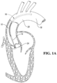
- FIG. 1A depicts an attempted delivery of cardiovascular implant 10 to a first target cardiovascular site using non-retractable delivery tip 14 of cardiovascular implant delivery system 16.
- the location of the first target cardiovascular site is merely an example, and it is to be understood that the location may vary from procedure to procedure.
- non-retractable delivery tip 14 tracks cardiovascular implant delivery system 16 through aortic arch 18 and ascending aorta 20.
- Cardiovascular implant 10 includes cardiovascular implant length that matches the length of first target cardiovascular site.
- First target cardiovascular site is adjacent to aortic valve 24 and within ascending aorta 20.
- Non-retractable delivery tip 14 interferes with the delivery of cardiovascular implant 10 to the first target cardiovascular site.
- a retractable, tapered tip for cardiovascular implant delivery systems reduces or eliminates this interference such that a cardiovascular implant may be delivered to a first target cardiovascular site adjacent to an aortic valve and within the ascending aorta.
- FIG. 1B depicts an attempted delivery of cardiovascular implant 50 to second target cardiovascular site 52 within heart wall 54 using non-retractable delivery tip 56 of cardiovascular implant delivery system 58.
- the location of second target cardiovascular site 52 is merely an example, and it is to be understood that the location may vary from procedure to procedure.
- non-retractable delivery tip 56 tracks cardiovascular implant delivery system 58 through aortic valve 60 into a region within heart wall 54.
- there is an interference between non-retractable delivery tip 56 and a distal region within heart wall 54 such that cardiovascular implant 50 does not reach second target cardiovascular site 52.
- Non-retractable delivery tip 56 interferes with the delivery of cardiovascular implant 50 to second target cardiovascular site 52.
- a retractable, tapered tip for cardiovascular implant delivery systems reduces or eliminates this interference such that a cardiovascular implant may be delivered to a second target cardiovascular site in a region within the heart wall.
- FIGS. 2A and 2B depict delivery tip system 110 of a delivery system configured to deliver a cardiovascular implant to a target cardiovascular site where delivery tip system 110 is shown in an undeformed state and a deformed state, respectively, according to one embodiment.
- Delivery tip system 110 includes delivery tip 112 and lumen 114, which is operatively connected to delivery tip 112.
- Delivery tip 112 has outer surface 116 and inner surface 118 with a thickness extending therebetween.
- Inner surface 118 defines inner cavity 120.
- Inner surface 118 may surround inner cavity 120 such that inner cavity 120 does not communicate with blood within the cardiovascular anatomy during deployment of delivery tip system 110.
- Inner surface 118 tapers inward from proximal end 122 to distal end 124.
- Delivery tip 112 includes base portion 126 adjacent to proximal end 128 of delivery tip 112 and tapered portion 130 adjacent to distal end 132 of delivery tip 112. Tapered portion 130 tapers inward from proximal end 134 to distal end 136. Tapered portion 130 is tapered so that delivery tip system 110 moves smoothly across vascular tissue without damaging (e.g., puncturing or perforating) tissue and/or dislodge material (e.g., plaque) as delivery tip system 110 is advanced through a patient's vasculature. As shown in Figures 2A and 2B , the profiles of inner cavity 120 and tapered portion 130 may be similar with the profile of inner cavity 120 being smaller in size than the profile of tapered portion 130. In one or more other embodiments, the profile of inner cavity 120 may be different than the profile of tapered portion 130.
- At least a portion of delivery tip 112 may be formed of a deformable material (e.g., a material configured to change in size or shape in response to an application of a force).
- tapered portion 130 of delivery tip 112 may be formed of a deformable material while base portion 126 is formed of a rigid or semi-rigid material so that delivery tip 112 deforms against base portion 126.
- Base portion 126 may be solid and not include an inner cavity to enhance the deformability of tapered portion 130 against base portion 126.
- tapered portion 130 and base portion 126 may be co-molded to each other.
- Non-limiting examples of deformable materials include silicone, deformable polymer materials such as urethane-coated silicone, polycarbonate-urethane, and urethane-coated silicone, and deformable metal materials such as NiTi alloy and stainless steel.
- At least a portion of delivery tip 112 e.g., tapered portion 130 may be formed of a deformable metal material embedded in a deformable polymer material depending on the strength and deformation characteristics identified for one or more delivery applications.
- Wire 138 is secured to a portion of distal end 124 of inner surface 118 through a fastener such as a suture, stitch, anchor, or hook, or a distal end of the sire 138 may have an anchor portion embedded in the wall of the tapered portion 130.
- wire 138 extends from distal end 124 of inner surface 118 through inner cavity 120 and lumen 114 to a handle portion of the delivery system.
- Wire 138 is operatively connected to the handle portion of the delivery system such that the handle may be actuated to exert pulling force P on wire 138 in a direction toward the clinician (i.e., a force in the proximal direction and away from the distal direction of the delivery system).
- the pulling force P deforms the deformable material of delivery tip 112 (e.g., tapered portion 130) such that the deformable material deforms in an outward radial direction R and an axial direction A.
- Radial direction R is generally orthogonal to axial direction A.
- the deformable material of delivery tip 112 may deform into inner cavity 120 such that inner cavity 120 acts as a crumple zone to control the deformation of delivery tip 112.
- the deformation of the deformable material of delivery tip 112 decreases the axial length of delivery tip 112 such that a target cardiovascular site is achieved without interfering with the anatomy in a cardiovascular region having short anatomical constraints.
- the axial length decrease may be any of the following values or in a range of any two of the following values: 0.1, 0.2, 0.3, 0.4, 0.5, 0.6, 0.7, 0.8, 0.9, 1.0, 1.1, 1.2, 1.3, 1.4, 1.5, 1.6, 1.7, 1.8, 1.9, 2.0, 2.1, 2.2, 2.3, 2.4, 2.5, 2.6, 2.7, 2.8, 2.9, and 3.0 centimeters.
- FIGS 3A and 3B depict delivery tip system 200 of a delivery system configured to deliver a cardiovascular implant to a target cardiovascular site where delivery tip system 200 is shown in an undeformed state and a deformed state, respectively, according to one embodiment.
- Delivery tip system 200 includes delivery tip 202 and lumen 204, which is operatively connected to delivery tip 202.
- Delivery tip 202 has an outer surface and an inner surface with a thickness extending therebetween.
- the inner surface defines inner cavity 206.
- the inner surface may surround inner cavity 206 such that inner cavity 206 does not communicate with blood within the cardiovascular anatomy during deployment of delivery tip system 200.
- the inner surface tapers inward from proximal end 208 to distal end 210.
- Delivery tip 202 includes base portion 212 adjacent to proximal end 208 of delivery tip 202 and tapered portion 214 adjacent to distal end 210 of delivery tip 202.
- Base portion 212 and tapered portion 214 may collectively form an integral delivery tip 202.
- Tapered portion 214 tapers inward from proximal end 208 to distal end 210.
- Tapered portion 214 is tapered so that delivery tip system 200 moves smoothly across vascular tissue without damaging (e.g., puncturing or perforating) tissue and/or dislodge material (e.g., plaque) as delivery tip system 200 is advanced through a patient's vasculature.
- the profiles of inner cavity 206 and delivery tip 202 may be similar with the profile of inner cavity 206 being smaller in size than the profile of delivery tip 202. In one or more other embodiments, the profile of inner cavity 206 may be different than the profile of delivery tip 202.
- base portion 212 may be formed of a deformable material.
- tapered portion 214 of delivery tip 202 may be formed of a deformable material while base portion 212 is formed of a rigid or semi-rigid material so that delivery tip 202 deforms against base portion 212.
- tapered portion 214 and base portion 212 may be co-molded to each other.
- deformable materials include deformable polymer materials such as those disclosed above, and deformable metal materials such as those disclosed above.
- At least a portion of delivery tip 202 may be formed of a deformable metal material embedded in a deformable polymer material depending on the strength and deformation characteristics identified for one or more delivery applications.
- the entire delivery tip 212 is formed of a deformable material.
- the delivery tip 212 may have a uniform thickness surrounding inner cavity 206.
- Wire 216 is secured to a portion of distal end 210 through a fastener such as a suture, stitch, anchor, or hook, or a distal end of the wire 138 may have an anchor portion embedded in the wall of the tapered portion 130.
- wire 216 extends from distal end 210 through inner cavity 206 and lumen 204 to a handle portion of the delivery system.
- Wire 216 is connected to the handle portion of the delivery system such that the handle portion may be actuated to exert pulling force P on wire 216 in a direction toward the clinician (i.e., a force in the proximal direction and away from the distal direction of the delivery system).
- the pulling force P deforms the deformable material of delivery tip 202 (e.g., tapered portion 214) such that the deformable material deforms in an outward radial direction R and an axial direction A.
- Radial direction R is generally orthogonal to axial direction A.
- the deformable material of delivery tip 202 may deform into inner cavity 206.
- Axial direction A and pulling force P are the same direction in one or more embodiments.
- the deformation of the deformable material of delivery tip 202 decreases the axial length of delivery tip 202 such that a target cardiovascular site is achieved without interfering with the anatomy in a cardiovascular region having short anatomical constraints.
- the axial length decrease from X1 to X2 may be any of the following values or in a range of any two of the following values: 0.1, 0.2, 0.3, 0.4, 0.5, 0.6, 0.7, 0.8, 0.9, 1.0, 1.1, 1.2, 1.3, 1.4, 1.5, 1.6, 1.7, 1.8, 1.9, 2.0, 2.1, 2.2, 2.3, 2.4, 2.5, 2.6, 2.7, 2.8, 2.9, and 3.0 centimeters.
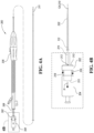
- Figure 4A depicts delivery system 300 including tip deformation actuator 302 configured to deform at least a portion of delivery tip 112 or 202 according to one embodiment.
- Figure 4B depicts a magnified, plan view of tip deformation actuator 302 shown in Figure 4A .
- Delivery system 300 also includes tip release actuator 304, as shown in Figures 4A and 4B .
- Tip release actuator 304 is operatively connected to a tip capture mechanism, in which manipulation (e.g., rotation) of tip release actuator 304 can release a tip capture mechanism from a cardiovascular implant (e.g., a stent graft) (not shown) to deploy the cardiovascular implant at a target cardiovascular site.
- a cardiovascular implant e.g., a stent graft
- Delivery system 300 may also include handle 306 operatively connected to a stent graft cover retraction mechanism, in which manipulation (e.g., rotation) of the handle relative to a threaded shaft can retract the stent graft cover, allowing the stent graft to expand radially outward.
- handle 306 operatively connected to a stent graft cover retraction mechanism, in which manipulation (e.g., rotation) of the handle relative to a threaded shaft can retract the stent graft cover, allowing the stent graft to expand radially outward.
- Delivery system 300 includes lumen 308 that is hollow. Lumen 308 extends from tip release actuator 304 through tip deformation actuator 302 and handle 306. Lumen 308 extends further to delivery tip 311. Tip deformation actuator 302 has proximal end 310 and distal end 312. Wire 314 is attached to distal end 312 via fastener 313. Wire 314 extends through lumen 308 to distal end 124 of inner surface 118 of delivery tip 112 or distal end 210 if delivery tip 202.
- tip deformation actuator 302 may be manipulated to move tip deformation actuator 302 in a proximal direction P, thereby deforming the deformable material of delivery tip 112 (e.g., delivery portion 130) or delivery tip 202 (e.g., tapered portion 214) to reduce the axial length of delivery tip 112 or 202.
- tip deformation actuator 302 may be in threaded engagement with tip release actuator 304 such that rotational movement of tip deformation actuator 302 into tip release actuator 304 moves tip deformation actuator 302 into tip release actuator 304 and holds wire 314 in a proximal position to maintain the deformation of delivery tip 112 or 202 while the cardiovascular implant is being deployed.
- tip deformation actuator 302 includes intermediate surface 316 and tip release actuator 304 includes distal end 318.
- Tip deformation actuator 302 may be manipulated in a proximal direction of the delivery system from a distal position (shown in Figure 4B ) to a proximal position where movement of tip deformation actuator 302 stops when intermediate surface 316 stops on distal end 318 of tip release actuator 304.
- the distance between the distal position and the proximal position may match the axial reduction in distance of the retractable tip through deformation (e.g., distance D of Figures 2A and 2B or the difference between distances X1 and X2 in Figures 3A and 3B ).
- Figure 5A depicts a plan view of retractable delivery tip 400 of cardiovascular delivery system 402 configured to deliver cardiovascular implant to target cardiovascular site 404 within heart wall 406 where retractable delivery tip 400 is shown in an unbent state according to one embodiment.
- Figure 5B depicts side view of retractable delivery tip 400 where retractable delivery tip 400 has transitioned from the unbent state into a bent state.
- the retractable delivery tip 400 may be formed of a deformable material.
- a distal portion of retractable delivery tip 400 includes spine 408 formed of a shape memory material or a hyperelastic material.
- the shape memory material may be a material that exists in a pre-deformed state (e.g., a pre-deformed shape) and a deformed state (e.g., a deformed shape).
- the shape memory material may be configured to deform from its pre-deformed state into its deformed state under a first condition (e.g., cold deformation) and to return to its pre-deformed state when a second condition (e.g., a stimulus) is applied.
- the first condition may be ambient conditions.
- the second condition may be a stimulus applied by heat, electricity, or mechanical actuation.
- the heat stimulus may heat the shape memory material to a transition temperature where the shape memory material transitions from its deformed state to its pre-deformed state.
- the electrical stimulus may be the application of a shielded or insulated current to the shape memory material so that the shape memory material transitions from its deformed state to its pre-deformed state.
- shape memory materials include shape memory alloys and shape memory polymers.
- shape memory alloys for application in the retractable, tapered tips of one or more embodiments include NiTi alloys, such as Nitinol, and Co alloys.
- Non-limiting examples of shape memory polymers for application in the retractable, tapered tips of one or more embodiments include thermoplastic elastomers, multiblock copolymers of macrodiols based on pentadeclaracton (PDL) and caprolacton (PCL) and a diisocyanate, polymer networks, amorphous polyurethane networks of trioles and/or tetroles and diisocyanate, and functionalized macrodiols.
- a hyperelastic material may be configured to reversibly deform to a high strain from a pre-deformed state to a deformed state in response to a high stress.
- Retractable delivery tip 400 includes base portion 410 at a proximal region of retractable delivery tip 400 and tapered portion 412 at a distal region of retractable delivery tip 400.
- spine 408 extends the entire length of tapered portion 412.
- the percentage extension of the length of spine 408 in tapered portion 412 may be any of the following percentages or in a range of any two of the following percentages: 50%, 55%, 60%, 65%, 70%, 75%, 80%, 85%, 90%, 95%, and 100%.
- Spine 408 may be partially or entirely embedded within the thickness of retractable delivery tip 400. Spine 408 may be secured to the inner or outer surface of tapered portion 412.
- spine 408 has a linear deformed shape and a curled pre-deformed shape, respectively.
- the curled pre-deformed shape reduces the axial length of retractable delivery tip 400 by the dimension X, as shown in Figure 5B .
- the curled pre-deformed shape shown in Figure 5B curls inward in a plane including retractable delivery tip 400.
- the pre-deformed shape may be a helical shape wrapped around the longitudinal axis of retractable delivery tip 400. The deformed shape may extend beyond the axial cross-sectional profile of base portion 410 of retractable delivery tip 400.
- tapered portion 412 itself may be formed from a shape memory material or a hyperelastic material and may be configured to transition from a linear/straight configuration as shown in Figure 5A to a curled or helical configuration as shown in Figure 5B .
- spine 408 may be configured to maintain tapered portion 412 in the linear configuration (e.g., deformed state) and upon its removal from tapered portion 412, the latter may transition to the curled configuration (e.g., pre-deformed or natural state).
- Spine 408 may be attached to an actuator, similar to in delivery system 300, or it may extend all the way back to and out of the handle such that it can be manually retracted by the operator.
- Figures 6A and 6B depict plan views of retractable delivery tip 500 of cardiovascular delivery system 502 configured to deliver cardiovascular implant 504.
- Figure 6A shows retractable delivery tip 500 in an unnested state.
- Figure 6B shows retractable delivery tip 500 in a nested state.
- Retractable delivery tip 500 includes tapered portion 506 decreasing in diameter from wide proximal portion 508 to narrow distal portion 510.
- Tapered portion 506 includes a number of links 512 or sections/portions. As shown in Figure 6A , each of the number of links 512 may be tapered and collectively form tapered portion 506. Each successive link 512 from wide proximal portion 508 to narrow distal portion 510 may reduce in diameter along the length of each successive link to form an overall tapered shape of tapered portion 506. Each adjacent pair of the number of links 512 is connected to each other such that the number of links 512 do not separate from each other during deployment or retrieval of cardiovascular implant 504.
- each adjacent pair of the number of links 512 is interlocked such that tapered portion 506 does not collapse while tracking to a target cardiovascular site.
- an actuator Prior to advancing to the target cardiovascular site, an actuator may be configured to unlock adjacent pairs of the number of links 512 such that the number of links 512 collapse into each other to form a nested state of retractable delivery tip 500 as shown in Figure 6B .
- the actuator may be located near the proximal end of the delivery system and connected to a wire that is also connected to retractable delivery tip 500. Actuation of the wire by the actuator makes the number of links 512 collapse on each other as shown in Figure 6B . The actuation may cause relative rotational movement between the links such that adjacent links become unlocked from each other, and thereby collapse.
- the collapsing of retractable delivery tip 500 into the nested state reduces the axial length of retractable delivery tip 500 by the dimension X, as shown in Figure 6B .
- the collapsing of retractable delivery tip 500 into the nested state reduces the axial length thereby allowing relatively shorter landing zones where anatomical structures may otherwise interfere with the delivery tip system, such as in the ascending aortic region and the heart valve region.
- a cardiovascular implant delivery system comprising:
- the actuator includes a handle portion disposed at a proximal region of the cardiovascular implant delivery system and a wire operatively connected to the handle portion and the tapered tip, the handle portion is configured to generate a pulling force on the wire in a proximal direction of the cardiovascular implant delivery system to reduce the axial length of the tapered portion.
- Clause 7 The cardiovascular implant delivery system of clause 1, wherein the tapered portion is formed of a deformable material.
- a retractable, tapered tip for a cardiovascular implant delivery system comprising: a retractable, tapered tip including a tapered portion tapering inward from a wide, proximal profile to a narrow, distal profile, the tapered portion having a non-retracted state and a retracted state, the tapered portion configured to retract from the non-retracted state to the retracted state during advancement of the retractable, tapered tip and a cardiovascular implant toward a target cardiovascular site to reduce an axial length of the tapered portion.
- Clause 10 The retractable, tapered tip of clause 8, wherein the retractable, tapered tip includes a base portion, the tapered portion extends from the base portion.
- Clause 11 The retractable, tapered tip of clause 10, wherein the base portion is formed of a non-deformable material configured to support deformation of the tapered portion from the non-retracted state to the retracted state.
- Clause 12 The retractable, tapered tip of clause 10, wherein the base portion has a constant profile along its length, and the base portion and the tapered portion collectively define a cavity within the retractable, tapered tip.
- Clause 13 The retractable, tapered tip of clause 8, wherein the tapered tip includes outer and inner surfaces, the inner surface of the tapered tip defines a cavity within the tapered tip.
- Clause 14 The retractable, tapered tip of clause 8, wherein the tapered tip includes a spine formed of a shape memory material having deformed and pre-deformed states, the non-retracted state is the deformed state, and the retracted state is the pre-deformed state.
- Clause 15 The retractable, tapered tip of clause 14, wherein the pre-deformed state includes a curled shape.
- Clause 16 The retractable, tapered tip of clause 8, wherein the tapered tip includes a number of nestable links configured to transition between an unnested state and a nested state, the non-retracted state is the unnested state, and the retracted state is the nested state.
- Clause 17 The retractable, tapered tip of clause 16, wherein the number of nestable links are configured to interlock in the unnested state and to collapse in the nested state.
- a method for delivering a cardiovascular implant to a target cardiovascular site comprising:
- Clause 19 The method of clause 18, further comprising deploying the cardiovascular implant at the target cardiovascular site after the retracting step.
- Clause 20 The method of clause 18, wherein the retracting step avoids the retractable, tapered tip from contacting a constrained anatomical structure adjacent the target cardiovascular site.
Landscapes
- Health & Medical Sciences (AREA)
- Engineering & Computer Science (AREA)
- Biomedical Technology (AREA)
- Cardiology (AREA)
- Life Sciences & Earth Sciences (AREA)
- Veterinary Medicine (AREA)
- Heart & Thoracic Surgery (AREA)
- Animal Behavior & Ethology (AREA)
- General Health & Medical Sciences (AREA)
- Public Health (AREA)
- Vascular Medicine (AREA)
- Transplantation (AREA)
- Oral & Maxillofacial Surgery (AREA)
- Biophysics (AREA)
- Pulmonology (AREA)
- Anesthesiology (AREA)
- Hematology (AREA)
- Prostheses (AREA)
Abstract
Description
- The present disclosure relates generally to a retractable, tapered tip for implant prosthetic delivery systems.
- An endovascular procedure may be used to deliver a cardiovascular implant in a minimally invasive manner to a target cardiovascular site of a patient. One such endovascular procedure may utilize a stent graft as the cardiovascular implant. The stent graft has a surgical graft covering and an expanding (e.g., self-expanding) metal frame. The stent graft may be placed at a target cardiovascular site to bridge a damaged and/or diseased blood vessel and/or heart tissue at the target cardiovascular site, thereby restoring the function of the damaged and/or diseased blood vessel and/or heart tissue.
- A target cardiovascular site may be accessed at a convenient and less traumatic entry point of the patient's body using an endovascular procedure. For instance, an implant (e.g., a stent graft) may be routed through the vasculature of a patient to the target cardiovascular site for deployment of the implant. Intraluminal deployment typically uses a delivery catheter with tubes or shafts arranged for relative axial movement. For example, an expandable stent graft may be compressed and disposed within a distal end of an outer shaft of the delivery catheter fixed to an inner shaft. The delivery catheter may then be maneuvered, typically tracked through a body lumen until a distal end of the delivery catheter and the stent graft are positioned at the target cardiovascular site. The expandable stent graft can then be deployed and radially expanded at the target cardiovascular site of the patient.
- According to one embodiment, a cardiovascular implant delivery system is disclosed. The cardiovascular implant delivery system includes a retractable, tapered tip including a tapered portion tapering inward from a wide, proximal profile to a narrow, distal profile. The tapered portion has a non-retracted state and a retracted state. The delivery system also includes a cardiovascular implant implantable at a target cardiovascular site. The delivery system further includes an actuator configured to retract the tapered portion from the non-retracted state to the retracted state during advancement of the retractable, tapered tip and the cardiovascular implant toward the target cardiovascular site to reduce an axial length of the tapered portion.
- According to another embodiment, a retractable, tapered tip for a cardiovascular implant delivery system is disclosed. The retractable, tapered tip includes a tapered portion tapering inward from a wide, proximal profile to a narrow, distal profile. The tapered portion has a non-retracted state and a retracted state. The tapered portion is configured to retract from the non-retracted state to the retracted state during advancement of the retractable, tapered tip and a cardiovascular implant toward a target cardiovascular site to reduce an axial length of the tapered portion.
- According to yet another embodiment, a method for delivering a cardiovascular implant to a target cardiovascular site. The method includes advancing a delivery system including a retractable, tapered tip and the cardiovascular implant toward the target cardiovascular site. The retractable, tapered tip has a non-retracted state and a retracted state. The method further includes retracting the retractable, tapered tip from the non-retracted state to the retracted state.
-
-
Figure 1A depicts an attempted delivery of a cardiovascular implant to a first target cardiovascular site using a non-retractable delivery tip of a cardiovascular implant delivery system. -
Figure 1B depicts an attempted delivery of a cardiovascular implant to a second target cardiovascular site within a heart wall using a non-retractable delivery tip of a cardiovascular implant delivery system. -
Figures 2A and 2B depict partial cross-sectional views of a retractable delivery tip of a cardiovascular delivery system configured to deliver a cardiovascular implant to a target cardiovascular site shown in cross section where the retractable delivery tip is shown in an undeformed state and a deformed state, respectively, according to one embodiment. -
Figures 3A and 3B depict plan views of a retractable delivery tip of a cardiovascular delivery system configured to deliver a cardiovascular implant to a target cardiovascular site shown in cross section where the retractable delivery tip is shown in an undeformed state and a deformed state, respectively, according to one embodiment. -
Figure 4A depicts a plan view of a delivery system including a tip deformation actuator configured to deform at least a portion of a delivery tip according to one embodiment. -
Figure 4B depicts a magnified, plan view of the tip deformation actuator shown inFigure 4A . -
Figure 5A depicts a plan view of a retractable delivery tip of a cardiovascular delivery system configured to deliver a cardiovascular implant to a target cardiovascular site where the retractable delivery tip is shown in an unbent state according to one embodiment. -
Figure 5B depicts a plan view of the retractable delivery tip ofFigure 5A where the retractable delivery tip has transitioned from the unbent state into a bent state according to one embodiment. -
Figure 6A depicts a plan view of a retractable delivery tip of a cardiovascular delivery system configured to deliver a cardiovascular implant to a target cardiovascular site where the retractable delivery tip is shown in an unnested state according to one embodiment. -
Figure 6B depicts a plan view of the retractable delivery tip ofFigure 6A where the retractable delivery tip has transitioned from the unnested state to a nested state according to one embodiment. - Embodiments of the present disclosure are described herein. It is to be understood, however, that the disclosed embodiments are merely examples and other embodiments can take various and alternative forms. The figures are not necessarily to scale; some features could be exaggerated or minimized to show details of particular components. Therefore, specific structural and functional details disclosed herein are not to be interpreted as limiting, but merely as a representative basis for teaching one skilled in the art to variously employ the embodiments. As those of ordinary skill in the art will understand, various features illustrated and described with reference to any one of the figures can be combined with features illustrated in one or more other figures to produce embodiments that are not explicitly illustrated or described. The combinations of features illustrated provide representative embodiments for typical applications. Various combinations and modifications of the features consistent with the teachings of this disclosure, however, could be desired for particular applications or implementations.
- Directional terms used herein are made with reference to the views and orientations shown in the exemplary figures. A central axis is shown in the figures and described below. Terms such as "outer" and "inner" are relative to the central axis. For example, an "outer" surface means that the surfaces faces away from the central axis, or is outboard of another "inner" surface. Terms such as "radial," "diameter," "circumference," etc. also are relative to the central axis. The terms "front," "rear," "upper" and "lower" designate directions in the drawings to which reference is made.
- Unless otherwise indicated, for the delivery system the terms "distal" and "proximal" are used in the following description with respect to a position or direction relative to a treating clinician. "Distal" and "distally" are positions distant from or in a direction away from the clinician, and "proximal" and "proximally" are positions near or in a direction toward the clinician. For the stent-graft prosthesis, "proximal" is the portion nearer the heart by way of blood flow path while "distal" is the portion of the stent-graft further from the heart by way of blood flow path.
- The following detailed description is merely exemplary in nature and is not intended to limit the invention or the application and uses of the invention. Although the description is in the context of treatment of heart tissue such as aortic valves, heart ventricles, and heart walls, and blood vessels such as the aorta, coronary, carotid, and renal arteries, the invention may also be used in any other body passageways where it is deemed useful.
- Cardiovascular implants are devices configured to replace malfunctioning, nonfunctioning, damaged and/or diseased blood vessels and/or heart tissue. These devices may imitate the function, form, and/or shape of working blood vessels and/or heart tissue. Cardiovascular implants may include cardiovascular prosthetics.
- Cardiovascular implants are delivered in a minimally invasive manner to avoid damage to vascular tissue and disruption of the function of surrounding anatomy during deployment. Cardiovascular implant delivery systems have been developed to address these concerns using a tapered tip at the distal end of the delivery system so that the delivery system may advance through the vasculature by the tapered tip gliding across the vessel tissue without dislodging material or puncturing tissue. The tapered tip includes a narrow, distal end and a broad, proximal end with a tapered body extending therebetween. In one configuration, the tapered tip has a frustoconical shape where the diameter increases from the narrow, distal end to the wide, proximal end. The diameter of the wide, proximal end may correspond to a diameter of an implant cover or sheath (e.g., a stent graft or prosthetic heart valve cover or sheath), which covers or sheaths an implant configured to be deployed at a target cardiovascular site.
- The axial length of the tip is extended by tapering the tip. The tapered tip design spans a longer length in an axial direction than the tip would otherwise span because of the taper. Therefore, a tapered tip occupies a length distal the implant. The length distal the implant may preclude or hinder deployment of an implant in regions of the cardiovascular system that have a limited amount of axial travel due to anatomical constraints. Such regions may include an aortic valve and/or a heart wall.
- Unless an access point different than the femoral access point is used, or the tapered tip is somehow removed after completing its tracking function, the implant may not accommodate patients that have short anatomical constraints. This problem may lead to fewer patients being treated by clinicians or clinicians pushing the limits of an implant delivery system, thereby potentially applying excessive pressure to delicate tissue within the cardiovascular system of a patient.
- A tapered tip may provide one or more functions through its design. First, the tapered tip may track smoothly and dilate (e.g., enlarge and widen) anatomy while advancing to a target cardiovascular site. Second, the tapered tip may be designed to not interfere with an adjustment of a clinician to the deployment location. Third, the tapered tip may be designed to not interfere with cardiovascular tissue during deployment. Fourth, the tapered tip may be designed so as not to interfere with a previously implanted vascular device. And finally, the tapered tip may be designed to be removed smoothly and gently through the newly implanted device and exit anatomy.
- According to one or more embodiments disclosed herein, a retractable, tapered tip for a cardiovascular delivery system is provided that provides one or more of the functions identified above while addressing delivery of a cardiovascular implant in a cardiovascular region having short anatomical constraints (e.g., an aortic valve and/or a heart wall). In one or more embodiments, a tapered tip that changes (e.g., reduces its axial length) in response to input from a clinician, such that a final deployment location (e.g., a target cardiovascular site) is achieved without interfering with anatomy in a cardiovascular region having short anatomical constraints (e.g., an aortic valve and/or a heart wall).
-
Figure 1A depicts an attempted delivery ofcardiovascular implant 10 to a first target cardiovascular site usingnon-retractable delivery tip 14 of cardiovascularimplant delivery system 16. The location of the first target cardiovascular site is merely an example, and it is to be understood that the location may vary from procedure to procedure. As shown inFigure 1A ,non-retractable delivery tip 14 tracks cardiovascularimplant delivery system 16 throughaortic arch 18 and ascendingaorta 20.Cardiovascular implant 10 includes cardiovascular implant length that matches the length of first target cardiovascular site. First target cardiovascular site is adjacent toaortic valve 24 and within ascendingaorta 20. As represented by the X inFigure 1A , there is an interference betweennon-retractable delivery tip 14 andaortic valve 24 such that the cardiovascular implant length cannot match the position of the length of the first target cardiovascular site.Non-retractable delivery tip 14 interferes with the delivery ofcardiovascular implant 10 to the first target cardiovascular site. In one or more embodiments, a retractable, tapered tip for cardiovascular implant delivery systems reduces or eliminates this interference such that a cardiovascular implant may be delivered to a first target cardiovascular site adjacent to an aortic valve and within the ascending aorta. -
Figure 1B depicts an attempted delivery ofcardiovascular implant 50 to second targetcardiovascular site 52 withinheart wall 54 usingnon-retractable delivery tip 56 of cardiovascularimplant delivery system 58. The location of second targetcardiovascular site 52 is merely an example, and it is to be understood that the location may vary from procedure to procedure. As shown inFigure 1B ,non-retractable delivery tip 56 tracks cardiovascularimplant delivery system 58 throughaortic valve 60 into a region withinheart wall 54. As represented by the X inFigure 1B , there is an interference betweennon-retractable delivery tip 56 and a distal region withinheart wall 54 such thatcardiovascular implant 50 does not reach second targetcardiovascular site 52.Non-retractable delivery tip 56 interferes with the delivery ofcardiovascular implant 50 to second targetcardiovascular site 52. In one or more embodiments, a retractable, tapered tip for cardiovascular implant delivery systems reduces or eliminates this interference such that a cardiovascular implant may be delivered to a second target cardiovascular site in a region within the heart wall. -
Figures 2A and 2B depictdelivery tip system 110 of a delivery system configured to deliver a cardiovascular implant to a target cardiovascular site wheredelivery tip system 110 is shown in an undeformed state and a deformed state, respectively, according to one embodiment.Delivery tip system 110 includesdelivery tip 112 andlumen 114, which is operatively connected todelivery tip 112.Delivery tip 112 hasouter surface 116 andinner surface 118 with a thickness extending therebetween.Inner surface 118 definesinner cavity 120.Inner surface 118 may surroundinner cavity 120 such thatinner cavity 120 does not communicate with blood within the cardiovascular anatomy during deployment ofdelivery tip system 110.Inner surface 118 tapers inward fromproximal end 122 todistal end 124.Delivery tip 112 includesbase portion 126 adjacent toproximal end 128 ofdelivery tip 112 and taperedportion 130 adjacent todistal end 132 ofdelivery tip 112.Tapered portion 130 tapers inward fromproximal end 134 todistal end 136.Tapered portion 130 is tapered so thatdelivery tip system 110 moves smoothly across vascular tissue without damaging (e.g., puncturing or perforating) tissue and/or dislodge material (e.g., plaque) asdelivery tip system 110 is advanced through a patient's vasculature. As shown inFigures 2A and 2B , the profiles ofinner cavity 120 and taperedportion 130 may be similar with the profile ofinner cavity 120 being smaller in size than the profile of taperedportion 130. In one or more other embodiments, the profile ofinner cavity 120 may be different than the profile of taperedportion 130. - At least a portion of
delivery tip 112 may be formed of a deformable material (e.g., a material configured to change in size or shape in response to an application of a force). In one or more embodiments, taperedportion 130 ofdelivery tip 112 may be formed of a deformable material whilebase portion 126 is formed of a rigid or semi-rigid material so thatdelivery tip 112 deforms againstbase portion 126.Base portion 126 may be solid and not include an inner cavity to enhance the deformability of taperedportion 130 againstbase portion 126. In this embodiment, taperedportion 130 andbase portion 126 may be co-molded to each other. Non-limiting examples of deformable materials include silicone, deformable polymer materials such as urethane-coated silicone, polycarbonate-urethane, and urethane-coated silicone, and deformable metal materials such as NiTi alloy and stainless steel. At least a portion of delivery tip 112 (e.g., tapered portion 130) may be formed of a deformable metal material embedded in a deformable polymer material depending on the strength and deformation characteristics identified for one or more delivery applications. -
Wire 138 is secured to a portion ofdistal end 124 ofinner surface 118 through a fastener such as a suture, stitch, anchor, or hook, or a distal end of thesire 138 may have an anchor portion embedded in the wall of the taperedportion 130. In one or more embodiments,wire 138 extends fromdistal end 124 ofinner surface 118 throughinner cavity 120 andlumen 114 to a handle portion of the delivery system.Wire 138 is operatively connected to the handle portion of the delivery system such that the handle may be actuated to exert pulling force P onwire 138 in a direction toward the clinician (i.e., a force in the proximal direction and away from the distal direction of the delivery system). The pulling force P deforms the deformable material of delivery tip 112 (e.g., tapered portion 130) such that the deformable material deforms in an outward radial direction R and an axial direction A. Radial direction R is generally orthogonal to axial direction A. The deformable material ofdelivery tip 112 may deform intoinner cavity 120 such thatinner cavity 120 acts as a crumple zone to control the deformation ofdelivery tip 112. - The deformation of the deformable material of
delivery tip 112 decreases the axial length ofdelivery tip 112 such that a target cardiovascular site is achieved without interfering with the anatomy in a cardiovascular region having short anatomical constraints. The axial length decrease may be any of the following values or in a range of any two of the following values: 0.1, 0.2, 0.3, 0.4, 0.5, 0.6, 0.7, 0.8, 0.9, 1.0, 1.1, 1.2, 1.3, 1.4, 1.5, 1.6, 1.7, 1.8, 1.9, 2.0, 2.1, 2.2, 2.3, 2.4, 2.5, 2.6, 2.7, 2.8, 2.9, and 3.0 centimeters. -
Figures 3A and 3B depictdelivery tip system 200 of a delivery system configured to deliver a cardiovascular implant to a target cardiovascular site wheredelivery tip system 200 is shown in an undeformed state and a deformed state, respectively, according to one embodiment.Delivery tip system 200 includesdelivery tip 202 andlumen 204, which is operatively connected todelivery tip 202.Delivery tip 202 has an outer surface and an inner surface with a thickness extending therebetween. The inner surface definesinner cavity 206. The inner surface may surroundinner cavity 206 such thatinner cavity 206 does not communicate with blood within the cardiovascular anatomy during deployment ofdelivery tip system 200. The inner surface tapers inward fromproximal end 208 todistal end 210.Delivery tip 202 includesbase portion 212 adjacent toproximal end 208 ofdelivery tip 202 and taperedportion 214 adjacent todistal end 210 ofdelivery tip 202.Base portion 212 and taperedportion 214 may collectively form anintegral delivery tip 202.Tapered portion 214 tapers inward fromproximal end 208 todistal end 210.Tapered portion 214 is tapered so thatdelivery tip system 200 moves smoothly across vascular tissue without damaging (e.g., puncturing or perforating) tissue and/or dislodge material (e.g., plaque) asdelivery tip system 200 is advanced through a patient's vasculature. As shown inFigures 3A and 3B , the profiles ofinner cavity 206 anddelivery tip 202 may be similar with the profile ofinner cavity 206 being smaller in size than the profile ofdelivery tip 202. In one or more other embodiments, the profile ofinner cavity 206 may be different than the profile ofdelivery tip 202. - At least a portion of
base portion 212 may be formed of a deformable material. In one or more embodiments, taperedportion 214 ofdelivery tip 202 may be formed of a deformable material whilebase portion 212 is formed of a rigid or semi-rigid material so thatdelivery tip 202 deforms againstbase portion 212. In this embodiment, taperedportion 214 andbase portion 212 may be co-molded to each other. Non-limiting examples of deformable materials include deformable polymer materials such as those disclosed above, and deformable metal materials such as those disclosed above. At least a portion of delivery tip 202 (e.g., tapered portion 214) may be formed of a deformable metal material embedded in a deformable polymer material depending on the strength and deformation characteristics identified for one or more delivery applications. In another embodiment, theentire delivery tip 212 is formed of a deformable material. Thedelivery tip 212 may have a uniform thickness surroundinginner cavity 206. -
Wire 216 is secured to a portion ofdistal end 210 through a fastener such as a suture, stitch, anchor, or hook, or a distal end of thewire 138 may have an anchor portion embedded in the wall of the taperedportion 130. In one or more embodiments,wire 216 extends fromdistal end 210 throughinner cavity 206 andlumen 204 to a handle portion of the delivery system.Wire 216 is connected to the handle portion of the delivery system such that the handle portion may be actuated to exert pulling force P onwire 216 in a direction toward the clinician (i.e., a force in the proximal direction and away from the distal direction of the delivery system). The pulling force P deforms the deformable material of delivery tip 202 (e.g., tapered portion 214) such that the deformable material deforms in an outward radial direction R and an axial direction A. Radial direction R is generally orthogonal to axial direction A. The deformable material ofdelivery tip 202 may deform intoinner cavity 206. - Axial direction A and pulling force P are the same direction in one or more embodiments. The deformation of the deformable material of
delivery tip 202 decreases the axial length ofdelivery tip 202 such that a target cardiovascular site is achieved without interfering with the anatomy in a cardiovascular region having short anatomical constraints. The axial length decrease from X1 to X2 may be any of the following values or in a range of any two of the following values: 0.1, 0.2, 0.3, 0.4, 0.5, 0.6, 0.7, 0.8, 0.9, 1.0, 1.1, 1.2, 1.3, 1.4, 1.5, 1.6, 1.7, 1.8, 1.9, 2.0, 2.1, 2.2, 2.3, 2.4, 2.5, 2.6, 2.7, 2.8, 2.9, and 3.0 centimeters. -
Figure 4A depictsdelivery system 300 includingtip deformation actuator 302 configured to deform at least a portion ofdelivery tip Figure 4B depicts a magnified, plan view oftip deformation actuator 302 shown inFigure 4A .Delivery system 300 also includestip release actuator 304, as shown inFigures 4A and 4B .Tip release actuator 304 is operatively connected to a tip capture mechanism, in which manipulation (e.g., rotation) oftip release actuator 304 can release a tip capture mechanism from a cardiovascular implant (e.g., a stent graft) (not shown) to deploy the cardiovascular implant at a target cardiovascular site.Delivery system 300 may also include handle 306 operatively connected to a stent graft cover retraction mechanism, in which manipulation (e.g., rotation) of the handle relative to a threaded shaft can retract the stent graft cover, allowing the stent graft to expand radially outward. -
Delivery system 300 includeslumen 308 that is hollow.Lumen 308 extends fromtip release actuator 304 throughtip deformation actuator 302 and handle 306.Lumen 308 extends further todelivery tip 311.Tip deformation actuator 302 hasproximal end 310 and distal end 312.Wire 314 is attached to distal end 312 viafastener 313.Wire 314 extends throughlumen 308 todistal end 124 ofinner surface 118 ofdelivery tip 112 ordistal end 210 ifdelivery tip 202. During deployment of a cardiovascular implant,tip deformation actuator 302 may be manipulated to movetip deformation actuator 302 in a proximal direction P, thereby deforming the deformable material of delivery tip 112 (e.g., delivery portion 130) or delivery tip 202 (e.g., tapered portion 214) to reduce the axial length ofdelivery tip tip deformation actuator 302 may be in threaded engagement withtip release actuator 304 such that rotational movement oftip deformation actuator 302 intotip release actuator 304 movestip deformation actuator 302 intotip release actuator 304 and holdswire 314 in a proximal position to maintain the deformation ofdelivery tip Figure 4B ,tip deformation actuator 302 includesintermediate surface 316 andtip release actuator 304 includesdistal end 318.Tip deformation actuator 302 may be manipulated in a proximal direction of the delivery system from a distal position (shown inFigure 4B ) to a proximal position where movement oftip deformation actuator 302 stops whenintermediate surface 316 stops ondistal end 318 oftip release actuator 304. The distance between the distal position and the proximal position may match the axial reduction in distance of the retractable tip through deformation (e.g., distance D ofFigures 2A and 2B or the difference between distances X1 and X2 inFigures 3A and 3B ). -
Figure 5A depicts a plan view ofretractable delivery tip 400 ofcardiovascular delivery system 402 configured to deliver cardiovascular implant to targetcardiovascular site 404 withinheart wall 406 whereretractable delivery tip 400 is shown in an unbent state according to one embodiment.Figure 5B depicts side view ofretractable delivery tip 400 whereretractable delivery tip 400 has transitioned from the unbent state into a bent state. - The
retractable delivery tip 400 may be formed of a deformable material. A distal portion ofretractable delivery tip 400 includesspine 408 formed of a shape memory material or a hyperelastic material. The shape memory material may be a material that exists in a pre-deformed state (e.g., a pre-deformed shape) and a deformed state (e.g., a deformed shape). The shape memory material may be configured to deform from its pre-deformed state into its deformed state under a first condition (e.g., cold deformation) and to return to its pre-deformed state when a second condition (e.g., a stimulus) is applied. The first condition may be ambient conditions. The second condition may be a stimulus applied by heat, electricity, or mechanical actuation. The heat stimulus may heat the shape memory material to a transition temperature where the shape memory material transitions from its deformed state to its pre-deformed state. The electrical stimulus may be the application of a shielded or insulated current to the shape memory material so that the shape memory material transitions from its deformed state to its pre-deformed state. Non-limiting examples of shape memory materials include shape memory alloys and shape memory polymers. Non-limiting examples of shape memory alloys for application in the retractable, tapered tips of one or more embodiments include NiTi alloys, such as Nitinol, and Co alloys. Non-limiting examples of shape memory polymers for application in the retractable, tapered tips of one or more embodiments include thermoplastic elastomers, multiblock copolymers of macrodiols based on pentadeclaracton (PDL) and caprolacton (PCL) and a diisocyanate, polymer networks, amorphous polyurethane networks of trioles and/or tetroles and diisocyanate, and functionalized macrodiols. A hyperelastic material may be configured to reversibly deform to a high strain from a pre-deformed state to a deformed state in response to a high stress. -
Retractable delivery tip 400 includesbase portion 410 at a proximal region ofretractable delivery tip 400 and taperedportion 412 at a distal region ofretractable delivery tip 400. As shown inFigures 5A and 5B ,spine 408 extends the entire length of taperedportion 412. The percentage extension of the length ofspine 408 in taperedportion 412 may be any of the following percentages or in a range of any two of the following percentages: 50%, 55%, 60%, 65%, 70%, 75%, 80%, 85%, 90%, 95%, and 100%.Spine 408 may be partially or entirely embedded within the thickness ofretractable delivery tip 400.Spine 408 may be secured to the inner or outer surface of taperedportion 412. As shown inFigures 5A and 5B ,spine 408 has a linear deformed shape and a curled pre-deformed shape, respectively. The curled pre-deformed shape reduces the axial length ofretractable delivery tip 400 by the dimension X, as shown inFigure 5B . The curled pre-deformed shape shown inFigure 5B curls inward in a plane includingretractable delivery tip 400. In another embodiment, the pre-deformed shape may be a helical shape wrapped around the longitudinal axis ofretractable delivery tip 400. The deformed shape may extend beyond the axial cross-sectional profile ofbase portion 410 ofretractable delivery tip 400. - In another embodiment, tapered
portion 412 itself may be formed from a shape memory material or a hyperelastic material and may be configured to transition from a linear/straight configuration as shown inFigure 5A to a curled or helical configuration as shown inFigure 5B . In this embodiment,spine 408 may be configured to maintaintapered portion 412 in the linear configuration (e.g., deformed state) and upon its removal from taperedportion 412, the latter may transition to the curled configuration (e.g., pre-deformed or natural state).Spine 408 may be attached to an actuator, similar to indelivery system 300, or it may extend all the way back to and out of the handle such that it can be manually retracted by the operator. -
Figures 6A and 6B depict plan views ofretractable delivery tip 500 ofcardiovascular delivery system 502 configured to delivercardiovascular implant 504.Figure 6A showsretractable delivery tip 500 in an unnested state.Figure 6B showsretractable delivery tip 500 in a nested state. -
Retractable delivery tip 500 includes taperedportion 506 decreasing in diameter from wideproximal portion 508 to narrowdistal portion 510.Tapered portion 506 includes a number oflinks 512 or sections/portions. As shown inFigure 6A , each of the number oflinks 512 may be tapered and collectively form taperedportion 506. Eachsuccessive link 512 from wideproximal portion 508 to narrowdistal portion 510 may reduce in diameter along the length of each successive link to form an overall tapered shape of taperedportion 506. Each adjacent pair of the number oflinks 512 is connected to each other such that the number oflinks 512 do not separate from each other during deployment or retrieval ofcardiovascular implant 504. As shown inFigure 6A , each adjacent pair of the number oflinks 512 is interlocked such thattapered portion 506 does not collapse while tracking to a target cardiovascular site. Prior to advancing to the target cardiovascular site, an actuator may be configured to unlock adjacent pairs of the number oflinks 512 such that the number oflinks 512 collapse into each other to form a nested state ofretractable delivery tip 500 as shown inFigure 6B . The actuator may be located near the proximal end of the delivery system and connected to a wire that is also connected toretractable delivery tip 500. Actuation of the wire by the actuator makes the number oflinks 512 collapse on each other as shown inFigure 6B . The actuation may cause relative rotational movement between the links such that adjacent links become unlocked from each other, and thereby collapse. The collapsing ofretractable delivery tip 500 into the nested state reduces the axial length ofretractable delivery tip 500 by the dimension X, as shown inFigure 6B . The collapsing ofretractable delivery tip 500 into the nested state reduces the axial length thereby allowing relatively shorter landing zones where anatomical structures may otherwise interfere with the delivery tip system, such as in the ascending aortic region and the heart valve region. - While exemplary embodiments are described above, it is not intended that these embodiments describe all possible forms encompassed by the claims. The words used in the specification are words of description rather than limitation, and it is understood that various changes can be made without departing from the spirit and scope of the disclosure. As previously described, the features of various embodiments can be combined to form further embodiments of the invention that may not be explicitly described or illustrated. While various embodiments could have been described as providing advantages or being preferred over other embodiments or prior art implementations with respect to one or more desired characteristics, those of ordinary skill in the art recognize that one or more features or characteristics can be compromised to achieve desired overall system attributes, which depend on the specific application and implementation. These attributes can include, but are not limited to cost, strength, durability, life cycle cost, marketability, appearance, packaging, size, serviceability, weight, manufacturability, ease of assembly, etc. As such, to the extent any embodiments are described as less desirable than other embodiments or prior art implementations with respect to one or more characteristics, these embodiments are not outside the scope of the disclosure and can be desirable for particular applications.
- Aspects and embodiments of the invention may be defined by the following clauses.
- Clause 1: A cardiovascular implant delivery system comprising:
- a retractable, tapered tip including a tapered portion tapering inward from a wide, proximal profile to a narrow, distal profile, the tapered portion having a non-retracted state and a retracted state;
- a cardiovascular implant implantable at a target cardiovascular site; and
- an actuator configured to retract the tapered portion from the non-retracted state to the retracted state during advancement of the retractable, tapered tip and the cardiovascular implant toward the target cardiovascular site to reduce an axial length of the tapered portion.
- Clause 2. The cardiovascular implant delivery system of clause 1, wherein the actuator includes a handle portion disposed at a proximal region of the cardiovascular implant delivery system and a wire operatively connected to the handle portion and the tapered tip, the handle portion is configured to generate a pulling force on the wire in a proximal direction of the cardiovascular implant delivery system to reduce the axial length of the tapered portion.
- Clause 3. The cardiovascular implant delivery system of clause 2, wherein the handle portion is rotatable in the proximal direction of the cardiovascular implant delivery system to reduce the axial length of the tapered portion.
- Clause 4. The cardiovascular implant delivery system of clause 2, wherein the tapered tip includes outer and inner surfaces, the inner surface of the tapered tip defines a cavity within the tapered tip, and the wire is secured to the inner surface.
- Clause 5. The cardiovascular implant delivery system of clause 2, wherein the handle portion is rotatable between an initial position where the tapered portion has the non-retracted state and a final position where the handle portion contacts a stop on a second handle portion.
- Clause 6. The cardiovascular implant delivery system of clause 2, wherein the wire is operatively connected to the handle portion via a fastener.
- Clause 7. The cardiovascular implant delivery system of clause 1, wherein the tapered portion is formed of a deformable material.
- Clause 8. A retractable, tapered tip for a cardiovascular implant delivery system, the retractable, tapered tip comprising:
a retractable, tapered tip including a tapered portion tapering inward from a wide, proximal profile to a narrow, distal profile, the tapered portion having a non-retracted state and a retracted state, the tapered portion configured to retract from the non-retracted state to the retracted state during advancement of the retractable, tapered tip and a cardiovascular implant toward a target cardiovascular site to reduce an axial length of the tapered portion. - Clause 9. The retractable, tapered tip of clause 8, wherein the tapered portion is formed of a deformable material, the deformable material is a deformable polymer, a deformable metal, or a combination thereof.
-
Clause 10. The retractable, tapered tip of clause 8, wherein the retractable, tapered tip includes a base portion, the tapered portion extends from the base portion. - Clause 11. The retractable, tapered tip of
clause 10, wherein the base portion is formed of a non-deformable material configured to support deformation of the tapered portion from the non-retracted state to the retracted state. - Clause 12. The retractable, tapered tip of
clause 10, wherein the base portion has a constant profile along its length, and the base portion and the tapered portion collectively define a cavity within the retractable, tapered tip. - Clause 13. The retractable, tapered tip of clause 8, wherein the tapered tip includes outer and inner surfaces, the inner surface of the tapered tip defines a cavity within the tapered tip.
-
Clause 14. The retractable, tapered tip of clause 8, wherein the tapered tip includes a spine formed of a shape memory material having deformed and pre-deformed states, the non-retracted state is the deformed state, and the retracted state is the pre-deformed state. - Clause 15. The retractable, tapered tip of
clause 14, wherein the pre-deformed state includes a curled shape. -
Clause 16. The retractable, tapered tip of clause 8, wherein the tapered tip includes a number of nestable links configured to transition between an unnested state and a nested state, the non-retracted state is the unnested state, and the retracted state is the nested state. - Clause 17. The retractable, tapered tip of
clause 16, wherein the number of nestable links are configured to interlock in the unnested state and to collapse in the nested state. -
Clause 18. A method for delivering a cardiovascular implant to a target cardiovascular site, the method comprising: - advancing a delivery system including a retractable, tapered tip and the cardiovascular implant toward the target cardiovascular site, the retractable, tapered tip having a non-retracted state and a retracted state; and
- retracting the retractable, tapered tip from the non-retracted state to the retracted state.
- Clause 19. The method of
clause 18, further comprising deploying the cardiovascular implant at the target cardiovascular site after the retracting step. -
Clause 20. The method ofclause 18, wherein the retracting step avoids the retractable, tapered tip from contacting a constrained anatomical structure adjacent the target cardiovascular site.
Claims (15)
- A cardiovascular implant delivery system comprising:a retractable, tapered tip including a tapered portion tapering inward from a wide, proximal profile to a narrow, distal profile, the tapered portion having a non-retracted state and a retracted state;a cardiovascular implant implantable at a target cardiovascular site; andan actuator configured to retract the tapered portion from the non-retracted state to the retracted state during advancement of the retractable, tapered tip and the cardiovascular implant toward the target cardiovascular site to reduce an axial length of the tapered portion.
- The cardiovascular implant delivery system of claim 1, wherein the actuator includes a handle portion disposed at a proximal region of the cardiovascular implant delivery system and a wire operatively connected to the handle portion and the tapered tip, the handle portion is configured to generate a pulling force on the wire in a proximal direction of the cardiovascular implant delivery system to reduce the axial length of the tapered portion.
- The cardiovascular implant delivery system of claim 2, wherein the handle portion is rotatable in the proximal direction of the cardiovascular implant delivery system to reduce the axial length of the tapered portion.
- The cardiovascular implant delivery system of claim 2, wherein the tapered tip includes outer and inner surfaces, the inner surface of the tapered tip defines a cavity within the tapered tip, and the wire is secured to the inner surface.
- The cardiovascular implant delivery system of claim 2, wherein the handle portion is rotatable between an initial position where the tapered portion has the non-retracted state and a final position where the handle portion contacts a stop on a second handle portion.
- The cardiovascular implant delivery system of claim 2, wherein the wire is operatively connected to the handle portion via a fastener.
- The cardiovascular implant delivery system of claim 1, wherein the tapered portion is formed of a deformable material.
- A retractable, tapered tip for a cardiovascular implant delivery system, the retractable, tapered tip comprising:
a retractable, tapered tip including a tapered portion tapering inward from a wide, proximal profile to a narrow, distal profile, the tapered portion having a non-retracted state and a retracted state, the tapered portion configured to retract from the non-retracted state to the retracted state during advancement of the retractable, tapered tip and a cardiovascular implant toward a target cardiovascular site to reduce an axial length of the tapered portion. - The retractable, tapered tip of claim 8, wherein the tapered portion is formed of a deformable material, the deformable material is a deformable polymer, a deformable metal, or a combination thereof.
- The retractable, tapered tip of claim 8, wherein the retractable, tapered tip includes a base portion, the tapered portion extends from the base portion.
- The retractable, tapered tip of claim 10, wherein the base portion is formed of a non-deformable material configured to support deformation of the tapered portion from the non-retracted state to the retracted state.
- The retractable, tapered tip of claim 10, wherein the base portion has a constant profile along its length, and the base portion and the tapered portion collectively define a cavity within the retractable, tapered tip.
- The retractable, tapered tip of claim 8, wherein the tapered tip includes outer and inner surfaces, the inner surface of the tapered tip defines a cavity within the tapered tip.
- The retractable, tapered tip of claim 8, wherein the tapered tip includes a spine formed of a shape memory material having deformed and pre-deformed states, the non-retracted state is the deformed state, and the retracted state is the pre-deformed state; and optionally wherein the pre-deformed state includes a curled shape.
- The retractable, tapered tip of claim 8, wherein the tapered tip includes a number of nestable links configured to transition between an unnested state and a nested state, the non-retracted state is the unnested state, and the retracted state is the nested state; and optionally wherein the number of nestable links are configured to interlock in the unnested state and to collapse in the nested state.
Applications Claiming Priority (1)
| Application Number | Priority Date | Filing Date | Title |
|---|---|---|---|
| US17/536,920 US20230165697A1 (en) | 2021-11-29 | 2021-11-29 | Retractable, tapered tip for cardiovascular implant delivery systems |
Publications (2)
| Publication Number | Publication Date |
|---|---|
| EP4186478A1 true EP4186478A1 (en) | 2023-05-31 |
| EP4186478B1 EP4186478B1 (en) | 2026-01-28 |
Family
ID=84360898
Family Applications (1)
| Application Number | Title | Priority Date | Filing Date |
|---|---|---|---|
| EP22208609.2A Active EP4186478B1 (en) | 2021-11-29 | 2022-11-21 | Retractable, tapered tip for cardiovascular implant delivery systems |
Country Status (3)
| Country | Link |
|---|---|
| US (1) | US20230165697A1 (en) |
| EP (1) | EP4186478B1 (en) |
| CN (1) | CN116172751A (en) |
Families Citing this family (1)
| Publication number | Priority date | Publication date | Assignee | Title |
|---|---|---|---|---|
| US12071228B1 (en) * | 2019-03-28 | 2024-08-27 | Snap Inc. | Drone with propeller guard configured as an airfoil |
Citations (4)
| Publication number | Priority date | Publication date | Assignee | Title |
|---|---|---|---|---|
| US20080255652A1 (en) * | 2007-04-12 | 2008-10-16 | Medtronic Vascular, Inc. | Expandable Tip Delivery System and Method |
| US20110137403A1 (en) * | 2008-07-18 | 2011-06-09 | Rasmussen Erick E | Introducer for endovascular implants |
| US20120277845A1 (en) * | 2009-12-17 | 2012-11-01 | Bowe Jason S | Delivery system with retractable proximal end |
| US20190015630A1 (en) * | 2015-03-19 | 2019-01-17 | Prytime Medical Devices, Inc. | System and method for low-profile occlusion balloon catheter |
Family Cites Families (8)
| Publication number | Priority date | Publication date | Assignee | Title |
|---|---|---|---|---|
| US5242457A (en) * | 1992-05-08 | 1993-09-07 | Ethicon, Inc. | Surgical instrument and staples for applying purse string sutures |
| US6045570A (en) * | 1997-02-11 | 2000-04-04 | Biointerventional Corporation | Biological sealant mixture and system for use in percutaneous occlusion of puncture sites and tracts in the human body and method |
| US6599254B2 (en) * | 2000-05-08 | 2003-07-29 | R. Edward Winters | Multi-feature steerable guidewire for vascular systems |
| US20070277845A1 (en) * | 2006-06-05 | 2007-12-06 | Blasco Alfredo Carlos C | Dental thread contained into a closed envelope and disposable therewith |
| US9192471B2 (en) * | 2007-01-08 | 2015-11-24 | Millipede, Inc. | Device for translumenal reshaping of a mitral valve annulus |
| JP6437469B2 (en) * | 2013-03-12 | 2018-12-12 | ベイリス メディカル カンパニー インコーポレイテッドBaylis Medical Company Inc. | Medical device having support structure |
| US10603198B2 (en) * | 2016-09-09 | 2020-03-31 | Cook Medical Technologies Llc | Prosthesis deployment system and method |
| US20200315605A1 (en) * | 2019-04-05 | 2020-10-08 | Acumed Llc | Bone anchor having deformable members |
-
2021
- 2021-11-29 US US17/536,920 patent/US20230165697A1/en not_active Abandoned
-
2022
- 2022-11-21 CN CN202211454048.0A patent/CN116172751A/en active Pending
- 2022-11-21 EP EP22208609.2A patent/EP4186478B1/en active Active
Patent Citations (4)
| Publication number | Priority date | Publication date | Assignee | Title |
|---|---|---|---|---|
| US20080255652A1 (en) * | 2007-04-12 | 2008-10-16 | Medtronic Vascular, Inc. | Expandable Tip Delivery System and Method |
| US20110137403A1 (en) * | 2008-07-18 | 2011-06-09 | Rasmussen Erick E | Introducer for endovascular implants |
| US20120277845A1 (en) * | 2009-12-17 | 2012-11-01 | Bowe Jason S | Delivery system with retractable proximal end |
| US20190015630A1 (en) * | 2015-03-19 | 2019-01-17 | Prytime Medical Devices, Inc. | System and method for low-profile occlusion balloon catheter |
Also Published As
| Publication number | Publication date |
|---|---|
| US20230165697A1 (en) | 2023-06-01 |
| CN116172751A (en) | 2023-05-30 |
| EP4186478B1 (en) | 2026-01-28 |
Similar Documents
| Publication | Publication Date | Title |
|---|---|---|
| CN110996855B (en) | Steerable Rail Delivery System | |
| EP3585320B2 (en) | Delivery system for radially constricting a stent graft | |
| JP6525470B2 (en) | Actively controllable stents, stent grafts, heart valves, and methods of controlling them | |
| EP1318769B1 (en) | Apparatus for delivering endoluminal prostheses | |
| EP3288499B1 (en) | Replacement mitral valve and delivery system for replacement mitral valve | |
| US20170304097A1 (en) | Stent-graft delivery system having an inner shaft component with a loading pad or covering on a distal segment thereof for stent retention | |
| US8992591B2 (en) | Delivery system with low longitudinal compressibility | |
| EP1140244B2 (en) | Self-expanding prosthesis with biocompatible coating | |
| US8876877B2 (en) | Centering for a TAA | |
| EP3007657B1 (en) | Stent delivery system | |
| CN111032141A (en) | Dual steerable sheath and method for deploying a medical device | |
| US20120239136A1 (en) | Flexible intraluminal stent | |
| CN108135697A (en) | Steerable delivery system and method of use for replacing a mitral valve | |
| EP1894545A1 (en) | Multiple in vivo implant delivery device | |
| US20200352705A1 (en) | Heart valve therapeutic device | |
| US20110152994A1 (en) | Implantable device | |
| EP3607916A1 (en) | Stent delivery with expansion assisting delivery wire | |
| US12599471B2 (en) | Expandable devices and associated systems and methods | |
| WO2012148715A2 (en) | Guidewire with two flexible end portions and method of accessing a branch vessel therewith | |
| US20090319019A1 (en) | Expandable Tip Delivery System For Endoluminal Prosthesis | |
| EP4186478B1 (en) | Retractable, tapered tip for cardiovascular implant delivery systems | |
| US20240245508A1 (en) | Heart valve implant apparatus | |
| EP3538036B1 (en) | Stent | |
| US10905572B2 (en) | Stent | |
| WO2025088488A1 (en) | Delivery system with bistable capsule |
Legal Events
| Date | Code | Title | Description |
|---|---|---|---|
| PUAI | Public reference made under article 153(3) epc to a published international application that has entered the european phase |
Free format text: ORIGINAL CODE: 0009012 |
|
| STAA | Information on the status of an ep patent application or granted ep patent |
Free format text: STATUS: REQUEST FOR EXAMINATION WAS MADE |
|
| 17P | Request for examination filed |
Effective date: 20221121 |
|
| AK | Designated contracting states |
Kind code of ref document: A1 Designated state(s): AL AT BE BG CH CY CZ DE DK EE ES FI FR GB GR HR HU IE IS IT LI LT LU LV MC ME MK MT NL NO PL PT RO RS SE SI SK SM TR |
|
| STAA | Information on the status of an ep patent application or granted ep patent |
Free format text: STATUS: EXAMINATION IS IN PROGRESS |
|
| 17Q | First examination report despatched |
Effective date: 20240327 |
|
| GRAP | Despatch of communication of intention to grant a patent |
Free format text: ORIGINAL CODE: EPIDOSNIGR1 |
|
| STAA | Information on the status of an ep patent application or granted ep patent |
Free format text: STATUS: GRANT OF PATENT IS INTENDED |
|
| INTG | Intention to grant announced |
Effective date: 20250818 |
|
| GRAS | Grant fee paid |
Free format text: ORIGINAL CODE: EPIDOSNIGR3 |
|
| GRAA | (expected) grant |
Free format text: ORIGINAL CODE: 0009210 |
|
| STAA | Information on the status of an ep patent application or granted ep patent |
Free format text: STATUS: THE PATENT HAS BEEN GRANTED |
|
| AK | Designated contracting states |
Kind code of ref document: B1 Designated state(s): AL AT BE BG CH CY CZ DE DK EE ES FI FR GB GR HR HU IE IS IT LI LT LU LV MC ME MK MT NL NO PL PT RO RS SE SI SK SM TR |
|
| REG | Reference to a national code |
Ref country code: CH Ref legal event code: F10 Free format text: ST27 STATUS EVENT CODE: U-0-0-F10-F00 (AS PROVIDED BY THE NATIONAL OFFICE) Effective date: 20260128 Ref country code: GB Ref legal event code: FG4D |
|
| REG | Reference to a national code |
Ref country code: DE Ref legal event code: R096 Ref document number: 602022029210 Country of ref document: DE |
|
| REG | Reference to a national code |
Ref country code: IE Ref legal event code: FG4D |
|
| REG | Reference to a national code |
Ref country code: NL Ref legal event code: MP Effective date: 20260128 |
|
| PG25 | Lapsed in a contracting state [announced via postgrant information from national office to epo] |
Ref country code: NL Free format text: LAPSE BECAUSE OF FAILURE TO SUBMIT A TRANSLATION OF THE DESCRIPTION OR TO PAY THE FEE WITHIN THE PRESCRIBED TIME-LIMIT Effective date: 20260128 |
|
| REG | Reference to a national code |
Ref country code: AT Ref legal event code: MK05 Ref document number: 1880189 Country of ref document: AT Kind code of ref document: T Effective date: 20260128 |
|
| PG25 | Lapsed in a contracting state [announced via postgrant information from national office to epo] |
Ref country code: RS Free format text: LAPSE BECAUSE OF FAILURE TO SUBMIT A TRANSLATION OF THE DESCRIPTION OR TO PAY THE FEE WITHIN THE PRESCRIBED TIME-LIMIT Effective date: 20260428 |
|
| PG25 | Lapsed in a contracting state [announced via postgrant information from national office to epo] |
Ref country code: ES Free format text: LAPSE BECAUSE OF FAILURE TO SUBMIT A TRANSLATION OF THE DESCRIPTION OR TO PAY THE FEE WITHIN THE PRESCRIBED TIME-LIMIT Effective date: 20260128 |
|
| PG25 | Lapsed in a contracting state [announced via postgrant information from national office to epo] |
Ref country code: PL Free format text: LAPSE BECAUSE OF FAILURE TO SUBMIT A TRANSLATION OF THE DESCRIPTION OR TO PAY THE FEE WITHIN THE PRESCRIBED TIME-LIMIT Effective date: 20260128 |
|
| PG25 | Lapsed in a contracting state [announced via postgrant information from national office to epo] |
Ref country code: GR Free format text: LAPSE BECAUSE OF FAILURE TO SUBMIT A TRANSLATION OF THE DESCRIPTION OR TO PAY THE FEE WITHIN THE PRESCRIBED TIME-LIMIT Effective date: 20260429 |
|
| REG | Reference to a national code |
Ref country code: LT Ref legal event code: MG9D |
|
| PG25 | Lapsed in a contracting state [announced via postgrant information from national office to epo] |
Ref country code: LT Free format text: LAPSE BECAUSE OF FAILURE TO SUBMIT A TRANSLATION OF THE DESCRIPTION OR TO PAY THE FEE WITHIN THE PRESCRIBED TIME-LIMIT Effective date: 20260128 |
|
| PG25 | Lapsed in a contracting state [announced via postgrant information from national office to epo] |
Ref country code: NO Free format text: LAPSE BECAUSE OF FAILURE TO SUBMIT A TRANSLATION OF THE DESCRIPTION OR TO PAY THE FEE WITHIN THE PRESCRIBED TIME-LIMIT Effective date: 20260428 |
|
| PG25 | Lapsed in a contracting state [announced via postgrant information from national office to epo] |
Ref country code: FI Free format text: LAPSE BECAUSE OF FAILURE TO SUBMIT A TRANSLATION OF THE DESCRIPTION OR TO PAY THE FEE WITHIN THE PRESCRIBED TIME-LIMIT Effective date: 20260128 Ref country code: AT Free format text: LAPSE BECAUSE OF FAILURE TO SUBMIT A TRANSLATION OF THE DESCRIPTION OR TO PAY THE FEE WITHIN THE PRESCRIBED TIME-LIMIT Effective date: 20260128 Ref country code: SE Free format text: LAPSE BECAUSE OF FAILURE TO SUBMIT A TRANSLATION OF THE DESCRIPTION OR TO PAY THE FEE WITHIN THE PRESCRIBED TIME-LIMIT Effective date: 20260128 |
|
| PG25 | Lapsed in a contracting state [announced via postgrant information from national office to epo] |
Ref country code: HR Free format text: LAPSE BECAUSE OF FAILURE TO SUBMIT A TRANSLATION OF THE DESCRIPTION OR TO PAY THE FEE WITHIN THE PRESCRIBED TIME-LIMIT Effective date: 20260128 |
|
| PG25 | Lapsed in a contracting state [announced via postgrant information from national office to epo] |
Ref country code: IS Free format text: LAPSE BECAUSE OF FAILURE TO SUBMIT A TRANSLATION OF THE DESCRIPTION OR TO PAY THE FEE WITHIN THE PRESCRIBED TIME-LIMIT Effective date: 20260528 Ref country code: PT Free format text: LAPSE BECAUSE OF FAILURE TO SUBMIT A TRANSLATION OF THE DESCRIPTION OR TO PAY THE FEE WITHIN THE PRESCRIBED TIME-LIMIT Effective date: 20260528 |
|
| PG25 | Lapsed in a contracting state [announced via postgrant information from national office to epo] |
Ref country code: LV Free format text: LAPSE BECAUSE OF FAILURE TO SUBMIT A TRANSLATION OF THE DESCRIPTION OR TO PAY THE FEE WITHIN THE PRESCRIBED TIME-LIMIT Effective date: 20260128 |
|
| PG25 | Lapsed in a contracting state [announced via postgrant information from national office to epo] |
Ref country code: BG Free format text: LAPSE BECAUSE OF FAILURE TO SUBMIT A TRANSLATION OF THE DESCRIPTION OR TO PAY THE FEE WITHIN THE PRESCRIBED TIME-LIMIT Effective date: 20260128 |