EP4186446A1 - Securement wire withstanding forces during deployment of implantable intravascular treatment device using a delivery and detachment system - Google Patents
Securement wire withstanding forces during deployment of implantable intravascular treatment device using a delivery and detachment system Download PDFInfo
- Publication number
- EP4186446A1 EP4186446A1 EP22209578.8A EP22209578A EP4186446A1 EP 4186446 A1 EP4186446 A1 EP 4186446A1 EP 22209578 A EP22209578 A EP 22209578A EP 4186446 A1 EP4186446 A1 EP 4186446A1
- Authority
- EP
- European Patent Office
- Prior art keywords
- proximal
- inner tube
- proximal inner
- wire
- weld
- Prior art date
- Legal status (The legal status is an assumption and is not a legal conclusion. Google has not performed a legal analysis and makes no representation as to the accuracy of the status listed.)
- Pending
Links
Images



Classifications
-
- A—HUMAN NECESSITIES
- A61—MEDICAL OR VETERINARY SCIENCE; HYGIENE
- A61B—DIAGNOSIS; SURGERY; IDENTIFICATION
- A61B17/00—Surgical instruments, devices or methods
- A61B17/12—Surgical instruments, devices or methods for ligaturing or otherwise compressing tubular parts of the body, e.g. blood vessels or umbilical cord
- A61B17/12022—Occluding by internal devices, e.g. balloons or releasable wires
- A61B17/12027—Type of occlusion
- A61B17/12031—Type of occlusion complete occlusion
-
- A—HUMAN NECESSITIES
- A61—MEDICAL OR VETERINARY SCIENCE; HYGIENE
- A61B—DIAGNOSIS; SURGERY; IDENTIFICATION
- A61B17/00—Surgical instruments, devices or methods
- A61B17/12—Surgical instruments, devices or methods for ligaturing or otherwise compressing tubular parts of the body, e.g. blood vessels or umbilical cord
- A61B17/12022—Occluding by internal devices, e.g. balloons or releasable wires
-
- A—HUMAN NECESSITIES
- A61—MEDICAL OR VETERINARY SCIENCE; HYGIENE
- A61B—DIAGNOSIS; SURGERY; IDENTIFICATION
- A61B17/00—Surgical instruments, devices or methods
- A61B17/12—Surgical instruments, devices or methods for ligaturing or otherwise compressing tubular parts of the body, e.g. blood vessels or umbilical cord
- A61B17/12022—Occluding by internal devices, e.g. balloons or releasable wires
- A61B17/12131—Occluding by internal devices, e.g. balloons or releasable wires characterised by the type of occluding device
- A61B17/1214—Coils or wires
- A61B17/12145—Coils or wires having a pre-set deployed three-dimensional shape
-
- A—HUMAN NECESSITIES
- A61—MEDICAL OR VETERINARY SCIENCE; HYGIENE
- A61B—DIAGNOSIS; SURGERY; IDENTIFICATION
- A61B17/00—Surgical instruments, devices or methods
- A61B17/12—Surgical instruments, devices or methods for ligaturing or otherwise compressing tubular parts of the body, e.g. blood vessels or umbilical cord
- A61B17/12022—Occluding by internal devices, e.g. balloons or releasable wires
- A61B17/12099—Occluding by internal devices, e.g. balloons or releasable wires characterised by the location of the occluder
- A61B17/12109—Occluding by internal devices, e.g. balloons or releasable wires characterised by the location of the occluder in a blood vessel
- A61B17/12113—Occluding by internal devices, e.g. balloons or releasable wires characterised by the location of the occluder in a blood vessel within an aneurysm
-
- A—HUMAN NECESSITIES
- A61—MEDICAL OR VETERINARY SCIENCE; HYGIENE
- A61B—DIAGNOSIS; SURGERY; IDENTIFICATION
- A61B17/00—Surgical instruments, devices or methods
- A61B17/12—Surgical instruments, devices or methods for ligaturing or otherwise compressing tubular parts of the body, e.g. blood vessels or umbilical cord
- A61B17/12022—Occluding by internal devices, e.g. balloons or releasable wires
- A61B17/12131—Occluding by internal devices, e.g. balloons or releasable wires characterised by the type of occluding device
- A61B17/1214—Coils or wires
-
- A—HUMAN NECESSITIES
- A61—MEDICAL OR VETERINARY SCIENCE; HYGIENE
- A61B—DIAGNOSIS; SURGERY; IDENTIFICATION
- A61B17/00—Surgical instruments, devices or methods
- A61B2017/00526—Methods of manufacturing
-
- A—HUMAN NECESSITIES
- A61—MEDICAL OR VETERINARY SCIENCE; HYGIENE
- A61B—DIAGNOSIS; SURGERY; IDENTIFICATION
- A61B17/00—Surgical instruments, devices or methods
- A61B17/12—Surgical instruments, devices or methods for ligaturing or otherwise compressing tubular parts of the body, e.g. blood vessels or umbilical cord
- A61B17/12022—Occluding by internal devices, e.g. balloons or releasable wires
- A61B2017/1205—Introduction devices
-
- A—HUMAN NECESSITIES
- A61—MEDICAL OR VETERINARY SCIENCE; HYGIENE
- A61B—DIAGNOSIS; SURGERY; IDENTIFICATION
- A61B17/00—Surgical instruments, devices or methods
- A61B17/12—Surgical instruments, devices or methods for ligaturing or otherwise compressing tubular parts of the body, e.g. blood vessels or umbilical cord
- A61B17/12022—Occluding by internal devices, e.g. balloons or releasable wires
- A61B2017/1205—Introduction devices
- A61B2017/12054—Details concerning the detachment of the occluding device from the introduction device
Definitions
- the present invention relates to a delivery and detachment system for an implantable intravascular treatment device (e.g., embolic coil) used during an endovascular treatment or procedure.
- the present invention is directed to a delivery and detachment system for implantation of an implantable intravascular treatment deice (e.g., embolic coil) in the intravascular treatment of a brain aneurysm.
- an implantable intravascular treatment deice e.g., embolic coil
- the securement wire is able to withstand forces during detachment/deployment of the implantable intravascular treatment device (e.g., embolic coil) at a target site.
- Implantable intravascular treatment devices are commonly used in endovascular procedures or treatments of various vascular ailments, for example, brain aneurysms.
- a guide catheter is inserted into the femoral artery in patient's leg and, while guided by imaging, navigated through the vessel to the target site in the brain (e.g., a proximal side of the aneurysm), as shown in Figure 1 .
- a microcatheter 100 may be tracked through the guide catheter to the proximal side of the aneurysm ( Figure 4 ).
- a delivery and detachment system 120 loaded with an implantable intravascular device (e.g., embolic coil) 105 is introduced via the microcatheter 100 and advanced to the proximal side of the aneurysm.
- the implantable intravascular treatment device (e.g., embolic coil) 105 is secured within the delivery and detachment system 120 via a securement wire (e.g., pull wire).
- the securement wire is translated (e.g., axially pulled in a proximal direction) releasing the implantable intravascular treatment device (e.g., embolic coil) to be deposited within the aneurysm ( Figure 2 showing a single deposited embolic coil).
- the implantable intravascular treatment device e.g., embolic coil
- the present invention is directed to an improved mechanical delivery and detachment system in which the implantable intravascular treatment device (e.g., embolic coil) is releasably secured to the distal end thereof via a securement wire that itself is robustly attached along an axial section thereof to the inner wall of the proximal inner tube via one or more supplemental connection points able to withstand forces during deployment.
- the implantable intravascular treatment device e.g., embolic coil
- An aspect of the present invention is directed to an improved mechanical delivery and detachment system in which the implantable intravascular treatment device (e.g., embolic coil) is releasably secured to the distal end thereof via a securement wire that itself is robustly attached along an axial section thereof to the inner wall of the proximal inner tube via one or more supplemental connection points able to withstand forces during deployment.
- the implantable intravascular treatment device e.g., embolic coil
- Another aspect of the present invention relates to a delivery and detachment system for an implantable intravascular treatment device, wherein the system includes: an outer delivery tube having a proximal end, an opposite distal end, and a lumen defined axially therein; and a proximal inner tube having a proximal end, an opposite distal end, and a lumen defined axially therein.
- the proximal inner tube is telescopically slidable within the lumen of the outer delivery tube and has a weld window radially inward cutout defined therein along an axial section thereof between but not including the proximal and distal ends.
- the system further including a securement wire disposed axially within the lumen of the proximal inner tube, wherein the securement wire is secured to an inner wall of the lumen of the proximal inner tube via at one supplemental connection point coinciding with the weld window.
- a still further aspect of the present invention is directed to a method of making the delivery and detachment system for an implantable intravascular treatment system described in the preceding paragraph.
- the proximal inner tube is assembled telescopically in the lumen of the outer delivery tube so that the proximal end of the proximal inner tube extends beyond the proximal end of the outer delivery tube without concealing the weld window.
- the securement wire and at least one positioning wire is threaded in a direction from the distal end to the proximal end of the proximal inner tube through the lumen of the proximal inner tube until the proximal end of each of the securement wire and the at least one positioning wire extends beyond the proximal end of the proximal inner tube.
- the securement wire is forced in direct physical contact with an inner wall of the lumen of the proximal inner tube coinciding with the weld window by manipulating the securement wire and/or the at least one positioning wire.
- At least one supplemental connection point is created between the securement wire and the inner wall of the lumen of the proximal inner tube along an axial section in direct physical contact with one another. Then the at least one positioning wire is withdrawn in a proximal direction from the proximal inner tube.
- distal or proximal are used in the following description with respect to a position or direction relative to the treating physician or medical interventionalist.
- distal or disally are a position distant from or in a direction away from the physician or interventionalist.
- Proximal or “proximally” or “proximate” are a position near or in a direction toward the physician or medical interventionist.
- occlusion or “clot” or “blockage” are used interchangeably.
- the delivery and detachment system comprises a proximal inner tube (e.g., proximal member) 505 telescopically slidable within an axial lumen of an outer delivery tube (e.g., pusher) 510.
- proximal inner tube e.g., proximal member
- outer delivery tube e.g., pusher
- a securement wire (e.g., pull wire) 515 extending axially through the lumen of the delivery and detachment system is fixedly attached at its proximal end to the proximal end of the proximal inner tube 505 via a proximal bead 570.
- An opposite distal end of the securement wire 515 is releasably secured to the implantable intravascular device (e.g., embolic coil) 530.
- Attachment of the implantable intravascular treatment device (e.g., embolic coil) to the securement wire is via a purely mechanical securement mechanism (e.g., translated release), that is, a mechanism releasable exclusively by translation (i.e., pulling in a linear (axial or longitudinal) direction on the securement wire 515 in a proximal direction (without the need for application of electrical and/or thermal heat)).
- a mechanical securement mechanism e.g., translated release
- the mechanical securement mechanism includes a U-shape loop wire 520 extending in a proximal direction through the lumen 508 of the delivery and detachment system.
- the U-shape loop wire 520 wire has two proximal ends extending in a proximal direction and affixed to the delivery and detachment system while its opposite closed distal end (forming a loop) is bent upwards threaded through an opening of a proximal key 525.
- a sufficient amount of the closed distal end of the U-shape loop wire 520 projects upwards through the opening of the proximal key 525 forming a loop (eyelet) through which the free distal end of the securement wire 515 is axially slidable/passable/threadable therethrough.
- the distal end of the proximal key 525 is receivable within an open proximal end of an embolic coil 530 secured in position thereto by a stretch restraint fiber 535 at a proximal end threaded through the opening at the distal end of the proximal key 525 and attached at an opposite distal end to a distal bead or cap 540.
- the implantable intravascular treatment device e.g., embolic coil
- the proximal bead 570 Minimal, if any, restraint prohibiting or minimizing dislodgement of the securement wire 515 from the proximal inner tube 505 is provided by the proximal bead 570 primarily serving to aid easy insertion in the delivery and detachment device.
- the implantable intravascular treatment device when forces imposed on the securement wire may exceed that of the break load of the wire itself, a high probability exists of unintended detachment of the securement wire 515 from the proximal inner tube 505 when the proximal bead 570 is the sole point connecting the two components.
- the design of the present inventive delivery and detachment system provides one or more supplemental connection points (e.g., spot welds) between the securement wire and the proximal inner tube thereby exceeding in overall strength the connection provided by the proximal bead 570 alone.
- supplemental connection points e.g., spot welds
- a laser cutout made radially inward in the proximal inner tube 505 creates a weld window 545 providing an access point through which the two components (securement wire 515 and proximal inner tube 505) are secured together via the creation of one or more supplemental connection points (e.g., one or more supplemental spot welds).
- supplemental connection points e.g., one or more supplemental spot welds.
- the one or more supplemental connection points are located along an axial section (between, but not including the proximal and distal ends) of the securement wire 515.
- the length in the axial/longitudinal direction as well as the length in a lateral direction that defines the weld window cutout in the proximal inner tube 505 is selected, as desired, with several competing factors.
- the cutout is sufficient in size to: (i) visibly position therein the securement wire in direct physical contact with the inner wall of the proximal inner tube; and (ii) allow for creation of the desired size and number of one or more supplemental connection point(s) (e.g., laser spot weld(s)) between the two components (e.g., the securement wire and the inner wall of the proximal inner tube)) to achieve a desired target strength.
- the proximal inner tube retains sufficient rigidity or strength (i.e., higher tensile strength - less frangible).
- a laser cutout sufficiently large in size is selected to accommodate the desired quantity and size spot weld(s) to prohibit or minimize detachment of the securement wire from the proximal inner tube, while a cutout too large in size may negatively diminish or weaken the integrity/rigidity (i.e., lower tensile strength - more frangible) of the proximal inner tube.
- the cutout may be designed with a width in a lateral direction in a range of approximately 0.0019 inches - approximately 0.0045 inches and a length in an axial direction in a range of approximately 0.012 inches - approximately 0.016 inches.
- the proximal edge of the most proximal weld window is preferably ⁇ approximately 1 mm in an axial direction from the proximal end/tip of the proximal inner tube.
- the securement wire 515 and proximal inner tube 505 Prior to creating the one or more lap spot welds (the one or more supplemental connection points) the securement wire 515 and proximal inner tube 505 are forced in direct physical contact with one another along an axial section (between but not including the respective proximal and distal ends). This is accomplished by filling the space in the lumen of the proximal inner tube 505 having the securement wire 515 threaded therethrough with one or more positioning wires 550, 550' as necessary to ensure proper fitment.
- the one or more positioning wires 550, 550' are manipulated forcing the securement wire 515 in direct physical contact against the inner wall of the proximal inner tube 505 along an axial region coinciding (aligned) with the weld window 545 so that one or more secure spot welds (supplemental connection point(s)) 560, 560' therebetween may be created.
- one or more positioning wire(s) 550, 550' are threaded either one at a time or simultaneously all together at the same time through the lumen of the proximal inner tube 505 with the securement wire 515 already threaded therethrough. It may be difficult to thread more than one positioning wire through the lumen of the proximal inner tube simultaneously at the same time. Moreover, it is contemplated that in order to obtain the optimum tightest fit multiple positioning wires differing in diameter may be employed through a series of trials or experimentation. For example, following insertion of the securement wire 515, next threaded through the lumen of the proximal inner tube 505 is a first positioning wire 550 having a diameter of approximately 0.0022".
- a second positioning wire 550' of the same diameter (approximately 0.0022") may be tried. If that size is too large in diameter to fit during a second attempt another wire having a slightly reduced diameter (e.g., 0.002”) may be tried. Once again, if unsuccessful another wire with an even smaller diameter (e.g., 0.018”) is attempted. This experimentation through multiple attempts or trials is repeated until the optimum tightest fitment is realized.
- two positioning wires 550, 550' are sequentially threaded one at a time through the lumen of the proximal inner tube 505 and the emerging/exiting proximal ends of each positioning wire is bent in similar fashion to that of the securement wire 515 ( Figure 6C ).
- the proximal inner tube 505 is held in place via a chuck.
- any one or more of the three wires e.g., the single securement wire 515 and one or both of the positioning wires 550, 550'
- manipulated e.g., rotated, twisted, or maneuvered
- Figure 6D e.g., rotated, twisted, or maneuvered
- Figure 6E such intended placement or positioning of the securement wire when achieved is referred to as the "securing position" ( Figure 6E ).
- the axial section of the securement wire 515 in direct physical contact with the inner wall of the proximal inner tube 505 is aligned/coincides/overlaps with the weld window 545 ( Figure 6E ) serving as an access point for performing the one or more spot welds (one or more supplemental connection points).
- the emerging/exiting proximal ends of the respective securement wire 515 and positioning wire(s) 550, 550' extend sufficiently beyond the end of the proximal inner tube (e.g., by at least approximately 1 cm) to allow for easy manipulation of the wires.
- Figure 6F is a side view of the proximal inner tube 505 with the securement wire 515 arranged in the securing position (the positioning wires are not shown).
- Line 555 denotes the axial section of direct physical contact of the securement wire 515 and the inner wall of the proximal inner tube 505.
- Sequential (one after the other) insertion (threading) of each positioning wire through the lumen of the proximal inner tube advantageously allows for the optimum tightest fit.
- two positioning wires threaded independently, one after the other, is illustrated and described, but any number of one or more positioning wires may be used to realize the optimum tightest fit.
- the sequential insertion of each positioning wire results in a desirable customized fit per piece.
- the securement wire and one or more positioning wire(s) may alternatively simultaneously (all together as a unit at the same time) be threaded through the lumen of the proximal inner tube.
- spot weld(s) 560, 560' supplemental connection points
- any number of one or more spot welds may be made. The greater the quantity of spot welds the more robust or stronger the connection or attachment between the securement wire 515 and proximal inner tube 505.
- Figures 7A & 7B depict respective top and side views of the weld window 545 of the proximal inner tube 505 with an exemplary 8 total spot weld bonds 560, 560' arranged consecutively in series in an axial direction along the axial section in which the securement wire 515 (e.g., having a diameter of approximately 0.0018") is forced by the positioning wires 550, 550' in direct physical contact with the inner wall of the proximal inner tube 505.
- the securement wire 515 e.g., having a diameter of approximately 0.0018
- More than one spot weld bond is preferred so that in the event of rupture or breakage of one of the distal spot welds those remaining spot welds in a proximal direction relative thereto ensure that the securement wire nevertheless remains secured to the proximal inner tube.
- the number, size, and arrangement of each of the spot weld bonds may be varied, as desired. All, some, or none of the spot welds may be the same in size and strength. The arrangement of all, some, or none of the spot welds may be uniformly or non-uniformly spaced apart from one another in an axial direction.
- the positioning wires 550, 550' may be made of a heat resistant material or coated with a lubricous outer layer (e.g., Polytetrafluoroethylene (PTFE)).
- PTFE Polytetrafluoroethylene
- the 2 largest in size and strongest in strength spot welds 560' act as a strain relief for the securement wire 515 preventing or minimizing breakage or rupture thereof. While the quantity of 6 smaller in size and weaker in strength spot welds 560 axially arranged one after the other in series in a distal direction following thereafter ensure connection between the components (e.g., securement wire and proximal inner tube) despite rupture or breakage of one or more of the smaller/weaker spot welds starting from the distal most end (furthest to the left in Figures 7A & 7B ). Furthermore, when employing more than one smaller/weaker spot weld the load is desirably more uniformly distributed or split among the welds thereby reducing the probability of breakage or rupture of any one weld bond.
- the 2 melt "pools" of material represent distinct spot welds 560' each larger in size and stronger in strength (relative to the subsequent 6 spot welds 560 arranged distally thereof) using a laser (e.g., Nd:YAG laser) at a relatively higher power setting.
- a laser e.g., Nd:YAG laser
- an inert gas e.g., argon gas
- Such relatively large/strong spot welds come at a cost of damaging/weakening the securement wire.
- the subsequent 6 individual spot welds 560 each smaller in size and weaker in strength provide reinforced strength with de minimis, if any, further damage/weakening of the securement wire.
- the first two welds 560' (two largest spot welds to the right) are created using a Nd:YAG laser having a higher output power (e.g., 30W - 35W) at a duration between 0.20 ms - 0.25 ms generating 0.007J square pulses.
- the next three welds 560 (starting from the proximal end) are created using the Nd:YAG laser at a lower/reduced output power (e.g., 25W - 30W) for the same duration (0.20 ms - 0.25 ms) generating 0.005J square pulses.
- the remaining three welds 560 are created using the same parameters as that of the lower/reduced output power (e.g., 25W - 30 W) but now with the laser beam out of focus (e.g., 0.4 mm - 0.5 mm, out of focus).
- the proximal bead 570 securing the proximal end of the securement wire to the proximal end of the proximal inner tube may be made at the same time as the supplemental connection points using the same laser, for example, at an output power of 600-700W at a duration of 0.4ms - 0.5ms.
- each spot weld may be realized by varying any one or more of the parameter settings (e.g., travel speed, current, and/or voltage). Specifically, the higher power and greater length of time the larger in size and stronger the spot weld (supplemental connection point).
- the laser beam may be focused or defocused, wherein the energy is diluted when the laser is defocused in comparison to that while focused.
- the 2 largest spot welds 560' having the higher power setting are formed with the laser beam focused, while of the smaller 6 spot welds 560 are created at the lower power setting.
- the 3 closest to the proximal end/tip of the proximal inner tube (those three smaller spot welds 560 furthest to the right) are formed while the laser beam is focused while the 3 furthest from the proximal end/tip of the proximal inner tube (the remaining three smaller spot welds 560 furthest to the left) are formed with the laser beam defocused. Focusing or defocusing of the laser beam is yet another parameter that may be used, as desired, to achieve the desired strength of any one of the welds.
- the strength of each weld may be selected, as desired.
- the strength of each weld may be selected to decrease with the weld closest to the proximal end/tip of the proximal inner tube being the strongest and the weld furthest from the proximal end/tip of the proximal inner tube being the weakest. Not only strength but spacing or arrangement of the welds may also be selected, as desired.
- the 6 weaker spot welds 560 are arranged consecutively in series in an axial direction with each spot weld arranged substantially equidistant from the adjacent spot weld.
- the separation distance in an axial direction of the spot weld furthest from the proximal end/tip of the inner tube (i.e., the spot weld furthest to the left) relative to the next spot weld adjacent to it (i.e., the next circle to the right) in a proximal direction may be greater relative to the distance separation between any adjacent spot welds of the remaining 5 weaker welds in a proximal direction.
- welds have an edge effect due to the HAZ, where the wire may break off at that point under load.
- the additional, smaller 5 welds (in a distal direction) distribute the load so that the HAZ border does not reduce the overall strength.
- Acting as a strain relief, in this example configuration the last two welds (furthest from the proximal end - furthest to the left) are spaced out/apart to aid in that distribution (creating a gradient of the load on the welds). This spacing need not always be employed but may be advantageous in certain applications.
- One factor in evaluating the number of welds (furthest from the proximal end) to be spaced apart from one another is the axial length of the weld window itself. That is, the longer the axial length of the weld window the more space available to be able to separate adjacent welds.
- each adhesive window is aligned in an axial direction with one another and separated radially approximately 180° from the weld window. The length in an axial direction of the adhesive window may vary so long as the adhesive is able to wick.
- the length in an axial direction of a single adhesive window or multiple adhesive windows together may span substantially the same length in an axial direction as that of the weld window.
- the length in an axial direction of a single adhesive window may be substantially smaller (e.g., a mere hole) relative to the larger length in an axial direction of the weld window.
- each adhesive window substantially coincides/aligns/overlaps with the weld window.
- each adhesive window 565 is cutout radially inward of the proximal inner tube 505.
- the length in a lateral direction of each adhesive window 565 is substantially equal to the length in a lateral direction of the weld window 545;
- each of the adhesive windows 565 coincides/aligns/overlaps within that of the weld window 545; and
- the adhesive windows 565 aligned with one another in an axial direction together as a unit are separated radially by approximately 180° from the weld window 545.
- the proximal tube With the one or more adhesive windows cutout the proximal tube is oriented on the chuck with the adhesive windows facing upwards.
- a biocompatible adhesive injected or deposited via the one or more adhesive windows 565 and wicks through the lumen of the proximal inner tube to the opposite side (e.g., 180 degrees in a radial direction) surrounding (flooding) the previously created one or more spot weld(s) forming a supplemental adhesive bond.
- the supplemental adhesive bond even greater forces imparted on the securement wire during detachment may be sustained without disconnecting.
- the proximal end of the weld window 545 is preferably approximately 1 mm from the proximal end of the proximal inner tube 505, while the distal end of the weld window 545 is approximately 1.6 mm from the proximal end of the proximal inner tube 505. Risk of breakage of the weakened wall of the proximal inner tube during use is mitigated with a weld window relatively small in length in an axial direction arranged relatively close to the proximal end of the proximal inner tube.
- the construction of the proximal inner tube is weakened with increased potential for breakage.
- slack is intentionally added so that the proximal inner tube 505 may be telescopically pushed/slid in a distal direction within the lumen of the outer delivery tube 510 until the weld window 545 is concealed/hidden therein. Thereafter, the outer delivery tube 510 is crimped securing in position the proximal inner tube 505 therein.
- the weakened or fragile area of the wall of the proximal inner tube surrounding the weld and adhesive windows are encased, concealed, protected, or shielded by the outer delivery tube providing both protection and rigidity/strength during regular use minimizing or eliminating any risk of breakage.
- Figure 10A is a side view (prior to loading of the implantable intravascular treatment device, e.g., embolic coil) with the securement wire 515 extending through the outer delivery tube 510 and secured by one or more laser welds (supplemental connection points generically represented as a single large circle exposed within the weld window) to the inner wall of the proximal inner tube 505.
- the proximal bead 570 may be welded to the proximal end of the proximal inner tube either independently of or at the time of creating the welds 560, 560'.
- allotted slack (e.g., approximately 0.3 mm) is preferably maintained in the securement wire (distally of the location of the welds) providing allowance for subsequent advancement as a unit of the proximal inner tube and securement wire secured thereto in a distal direction into the outer delivery tube.
- the length in an axial direction from the proximal end/tip of the proximal inner tube to the distal edge of the weld window is preferably approximately 1.0 mm, while the proximal end of the proximal inner tube preferably extends in a proximal direction from the proximal end of the outer delivery tube by approximately 13 mm - approximately 16 mm.
- the implantable intravascular treatment device e.g., embolic coil
- the implantable intravascular treatment device e.g., embolic coil
- the proximal inner tube together with the securement wire secured thereto via the one or more spot welds (supplemental connection points) as a unit is then advanced in a distal direction until the entire weld window 545 (along with the adhesive windows, spot welds and adhesive welds) is fully concealed, protected, or shielded by the outer delivery tube 510 (hereinafter referred to as the "concealed position") ( Figure 10B ).
- the proximal inner tube 505 is advanced (axially slid or pushed in a distal direction) through the lumen of the outer delivery tube 510 by approximately 0.3 mm, whereby approximately 1.3 mm of the proximal inner tube 505 remains exposed (i.e., not concealed, protected, or shielded by the outer delivery tube).
- the proximal inner tube 505 and securement wire 515 together as a unit may be maintained in place in the concealed position by crimping 575 or otherwise radially mechanically compressing the outer delivery tube 510 reducing the inner diameter of its lumen distally of the distal edge of the weld window (represented in Figure 10B by the dashed semi-circle).
- the present inventive delivery and detachment system has been shown and described with respect to implantation of an embolic coil during a coil embolization procedure in the treatment of an intracranial aneurysm. It is contemplated and within the intended scope of the present invention to utilize the present inventive delivery and detachment system for delivering other types of implantable intravascular treatment devices used in other endovascular treatment procedures.
Landscapes
- Health & Medical Sciences (AREA)
- Surgery (AREA)
- Life Sciences & Earth Sciences (AREA)
- Heart & Thoracic Surgery (AREA)
- Molecular Biology (AREA)
- Vascular Medicine (AREA)
- Engineering & Computer Science (AREA)
- Biomedical Technology (AREA)
- Reproductive Health (AREA)
- Medical Informatics (AREA)
- Nuclear Medicine, Radiotherapy & Molecular Imaging (AREA)
- Animal Behavior & Ethology (AREA)
- General Health & Medical Sciences (AREA)
- Public Health (AREA)
- Veterinary Medicine (AREA)
- Neurosurgery (AREA)
- Surgical Instruments (AREA)
- Media Introduction/Drainage Providing Device (AREA)
Abstract
Description
- The present invention relates to a delivery and detachment system for an implantable intravascular treatment device (e.g., embolic coil) used during an endovascular treatment or procedure. In particular, the present invention is directed to a delivery and detachment system for implantation of an implantable intravascular treatment deice (e.g., embolic coil) in the intravascular treatment of a brain aneurysm. In the present inventive improved delivery and detachment system the securement wire is able to withstand forces during detachment/deployment of the implantable intravascular treatment device (e.g., embolic coil) at a target site.
- Implantable intravascular treatment devices are commonly used in endovascular procedures or treatments of various vascular ailments, for example, brain aneurysms. Typically, a guide catheter is inserted into the femoral artery in patient's leg and, while guided by imaging, navigated through the vessel to the target site in the brain (e.g., a proximal side of the aneurysm), as shown in
Figure 1 . In a particular application or use, with the distal end of theguide catheter 125 properly positioned on a proximal side of the aneurysm, amicrocatheter 100 may be tracked through the guide catheter to the proximal side of the aneurysm (Figure 4 ). Next, a delivery anddetachment system 120 loaded with an implantable intravascular device (e.g., embolic coil) 105 is introduced via themicrocatheter 100 and advanced to the proximal side of the aneurysm. During delivery to the target site, the implantable intravascular treatment device (e.g., embolic coil) 105 is secured within the delivery anddetachment system 120 via a securement wire (e.g., pull wire). Once properly positioned at the target site (e.g., at the location on a proximal side of the aneurysm) the securement wire is translated (e.g., axially pulled in a proximal direction) releasing the implantable intravascular treatment device (e.g., embolic coil) to be deposited within the aneurysm (Figure 2 showing a single deposited embolic coil). This process is repeated until the area of the vessel with the weakened wall is tightly packed with numerous embolic coils occluding blow flow thereto thereby preventing rupture, as depicted inFigure 3 . - The present invention is directed to an improved mechanical delivery and detachment system in which the implantable intravascular treatment device (e.g., embolic coil) is releasably secured to the distal end thereof via a securement wire that itself is robustly attached along an axial section thereof to the inner wall of the proximal inner tube via one or more supplemental connection points able to withstand forces during deployment.
- An aspect of the present invention is directed to an improved mechanical delivery and detachment system in which the implantable intravascular treatment device (e.g., embolic coil) is releasably secured to the distal end thereof via a securement wire that itself is robustly attached along an axial section thereof to the inner wall of the proximal inner tube via one or more supplemental connection points able to withstand forces during deployment.
- Another aspect of the present invention relates to a delivery and detachment system for an implantable intravascular treatment device, wherein the system includes: an outer delivery tube having a proximal end, an opposite distal end, and a lumen defined axially therein; and a proximal inner tube having a proximal end, an opposite distal end, and a lumen defined axially therein. The proximal inner tube is telescopically slidable within the lumen of the outer delivery tube and has a weld window radially inward cutout defined therein along an axial section thereof between but not including the proximal and distal ends. The system further including a securement wire disposed axially within the lumen of the proximal inner tube, wherein the securement wire is secured to an inner wall of the lumen of the proximal inner tube via at one supplemental connection point coinciding with the weld window.
- A still further aspect of the present invention is directed to a method of making the delivery and detachment system for an implantable intravascular treatment system described in the preceding paragraph. Initially, the proximal inner tube is assembled telescopically in the lumen of the outer delivery tube so that the proximal end of the proximal inner tube extends beyond the proximal end of the outer delivery tube without concealing the weld window. Then, the securement wire and at least one positioning wire is threaded in a direction from the distal end to the proximal end of the proximal inner tube through the lumen of the proximal inner tube until the proximal end of each of the securement wire and the at least one positioning wire extends beyond the proximal end of the proximal inner tube. Next, the securement wire is forced in direct physical contact with an inner wall of the lumen of the proximal inner tube coinciding with the weld window by manipulating the securement wire and/or the at least one positioning wire. Within the weld window, at least one supplemental connection point is created between the securement wire and the inner wall of the lumen of the proximal inner tube along an axial section in direct physical contact with one another. Then the at least one positioning wire is withdrawn in a proximal direction from the proximal inner tube.
- The foregoing and other features of the present invention will be more readily apparent from the following detailed description and drawings illustrative of the invention wherein like reference numbers refer to similar elements throughout the several views and in which:
-
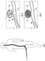
Figure 1 depicts a pathway or route of navigation by the guide catheter through the femoral artery to a target site in the brain; -
Figure 2 illustrates a single implantable intravascular treatment device (e.g., embolic coil) deployed/deposited in an aneurysm using the detachment and detachment system withdrawn; -
Figure 3 represents an aneurysm packed with a plurality of embolic coils after withdraw of the microcatheter; -
Figure 4 is a side view of a Prior Art delivery and detachment system loaded with an embolic coil during an exemplary application in which the delivery and detachment system is disposed within a microcatheter which, in turn, is disposed in a guide catheter; -
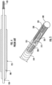
Figure 5 is a perspective cut away view of a distal section of an exemplary mechanism including a securement wire for releasably securing the implantable intravascular treatment device (e.g., embolic coil) to the distal end of the present inventive delivery and detachment system; -
Figure 6A depicts the proximal inner tube passing over the securement wire; -
Figure 6B illustrates the bending of the portion of the proximal end of the securement wire emerging/exiting from the proximal end of the proximal inner tube; -
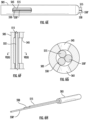
Figure 6C represents an exemplary proximal inner tube and the securement wire threaded therethrough together as a unit being pulled over a pair of positioning wires; -
Figure 6D depicts the manipulation of one or more of the wires (e.g., securement wire and pair of positioning wires) to force the securement wire in direct physical contact with the inner wall of the proximal inner tube along an axial section coinciding with the weld window; -
Figure 6E is a side view of the proximal inner tube showing the securement wire and inner wall of the proximal inner tube in direct physical contact along an axial section coinciding with the weld window (hereinafter referred to as the "securing position"); -
Figure 6F is a side view of the securement wire in the securing position (i.e., forced in direct physical contact with the inner wall of the proximal inner tube along an axial section coinciding with the weld window) (the positioning wires are not shown); -
Figure 6G is a radial cross-sectional view along lines VI(G)-VI(G) ofFigure 6F illustrating the securement wire in the securing position prior to being welded to the inner wall of the proximal inner tube; -
Figure 6H is an isometric view of the simultaneous threading of three wires (e.g., securement wire and pair of positioning wires) together as a unit through the proximal inner tube; -
Figure 7A is a top view of an exemplary proximal inner tube with a laser cut weld window through which is visible a series of 8 spot welds; -
Figure 7B is the side view of the proximal inner tube ofFigure 7A ; -
Figure 7C is a radial cross-sectional view along lines VI((C) - VII(C) ofFigure 7B ; -
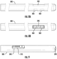
Figure 8A is a side view of an exemplary proximal inner tube having two adhesive windows separated radially 180° from and axially aligned with that of a single weld window; -
Figure 8B is a top view of the proximal inner tube ofFigure 8A depicting the axial alignment of the two adhesive windows within the single weld window; -
Figure 9 is a side view of an alternative configuration of 7 spot welds wherein the spot weld furthest from the proximal end of the securement wire (furthest to the left) has a larger separation distance in an axial direction relative to the next adjacent spot weld in comparison to the separation distance in an axial direction between any other adjacent spot welds in a proximal direction; -
Figure 10A is a side view representation of the securement wire welded to the proximal inner tube together as a unit assembled in the outer delivery tube, prior to loading the implantable intravascular device; and -
Figure 10B is a side view representation, after loading of the implantable intravascular device, the proximal inner tube with the securement wire welded thereto telescopically advanced in a distal direction whereby the weld window (depicted by the dashed semicircle) is concealed/shielded/covered/protected by the outer delivery tube physically crimped to maintain the proximal inner tube in place in this concealing position. - In the description, the terms "distal" or "proximal" are used in the following description with respect to a position or direction relative to the treating physician or medical interventionalist. "Distal" or "distally" are a position distant from or in a direction away from the physician or interventionalist. "Proximal" or "proximally" or "proximate" are a position near or in a direction toward the physician or medical interventionist. The terms "occlusion", "clot" or "blockage" are used interchangeably.
- During an endovascular treatment procedure (e.g., coil embolization), it is desirable for the delivery and detachment system to reliably and accurately deliver the implantable intravascular treatment device (e.g., embolic coil) to a precise location or target site (e.g., aneurysm) within a vessel or artery; and, once properly positioned, ensure complete deployment (detachment or separation) of the implantable intravascular treatment device from the system. Referring to
Figure 10A , the delivery and detachment system comprises a proximal inner tube (e.g., proximal member) 505 telescopically slidable within an axial lumen of an outer delivery tube (e.g., pusher) 510. A securement wire (e.g., pull wire) 515 extending axially through the lumen of the delivery and detachment system is fixedly attached at its proximal end to the proximal end of the proximalinner tube 505 via aproximal bead 570. An opposite distal end of thesecurement wire 515 is releasably secured to the implantable intravascular device (e.g., embolic coil) 530. Attachment of the implantable intravascular treatment device (e.g., embolic coil) to the securement wire is via a purely mechanical securement mechanism (e.g., translated release), that is, a mechanism releasable exclusively by translation (i.e., pulling in a linear (axial or longitudinal) direction on thesecurement wire 515 in a proximal direction (without the need for application of electrical and/or thermal heat)). In the exemplary configuration of the distal end of the delivery and detachment system depicted inFigure 5 the mechanical securement mechanism includes aU-shape loop wire 520 extending in a proximal direction through the lumen 508 of the delivery and detachment system. TheU-shape loop wire 520 wire has two proximal ends extending in a proximal direction and affixed to the delivery and detachment system while its opposite closed distal end (forming a loop) is bent upwards threaded through an opening of aproximal key 525. A sufficient amount of the closed distal end of theU-shape loop wire 520 projects upwards through the opening of theproximal key 525 forming a loop (eyelet) through which the free distal end of thesecurement wire 515 is axially slidable/passable/threadable therethrough. In turn, the distal end of theproximal key 525 is receivable within an open proximal end of anembolic coil 530 secured in position thereto by astretch restraint fiber 535 at a proximal end threaded through the opening at the distal end of theproximal key 525 and attached at an opposite distal end to a distal bead orcap 540. Thus, when the distal end of thesecurement wire 515 is engaged within the closed distal end of theU-shape loop wire 520 the implantable intravascular treatment device (e.g., embolic coil) 530 is secured to the distal end of the delivery and detachment system. - Minimal, if any, restraint prohibiting or minimizing dislodgement of the
securement wire 515 from the proximalinner tube 505 is provided by theproximal bead 570 primarily serving to aid easy insertion in the delivery and detachment device. During detachment of the implantable intravascular treatment device when forces imposed on the securement wire may exceed that of the break load of the wire itself, a high probability exists of unintended detachment of thesecurement wire 515 from the proximalinner tube 505 when theproximal bead 570 is the sole point connecting the two components. The design of the present inventive delivery and detachment system provides one or more supplemental connection points (e.g., spot welds) between the securement wire and the proximal inner tube thereby exceeding in overall strength the connection provided by theproximal bead 570 alone. - A laser cutout made radially inward in the proximal
inner tube 505 creates aweld window 545 providing an access point through which the two components (securement wire 515 and proximal inner tube 505) are secured together via the creation of one or more supplemental connection points (e.g., one or more supplemental spot welds). These one or more supplemental connection points being in addition to that of theproximal bead 570 disposed at the proximal end of thesecurement wire 515 securing it to the proximal end of the proximalinner tube 505. In contrast to the arrangement of theproximal bead 570 located at the proximal end of thesecurement wire 515, the one or more supplemental connection points are located along an axial section (between, but not including the proximal and distal ends) of thesecurement wire 515. The length in the axial/longitudinal direction as well as the length in a lateral direction that defines the weld window cutout in the proximalinner tube 505 is selected, as desired, with several competing factors. On the one hand, the cutout is sufficient in size to: (i) visibly position therein the securement wire in direct physical contact with the inner wall of the proximal inner tube; and (ii) allow for creation of the desired size and number of one or more supplemental connection point(s) (e.g., laser spot weld(s)) between the two components (e.g., the securement wire and the inner wall of the proximal inner tube)) to achieve a desired target strength. While on the other hand, the proximal inner tube retains sufficient rigidity or strength (i.e., higher tensile strength - less frangible). Addressing each factor, clearly a laser cutout sufficiently large in size (width in a lateral direction and/or length in an axial direction) is selected to accommodate the desired quantity and size spot weld(s) to prohibit or minimize detachment of the securement wire from the proximal inner tube, while a cutout too large in size may negatively diminish or weaken the integrity/rigidity (i.e., lower tensile strength - more frangible) of the proximal inner tube. Keeping these competing factors in mind, by way of example, the cutout may be designed with a width in a lateral direction in a range of approximately 0.0019 inches - approximately 0.0045 inches and a length in an axial direction in a range of approximately 0.012 inches - approximately 0.016 inches. In addition, the proximal edge of the most proximal weld window is preferably ≥ approximately 1 mm in an axial direction from the proximal end/tip of the proximal inner tube. - Prior to creating the one or more lap spot welds (the one or more supplemental connection points) the
securement wire 515 and proximalinner tube 505 are forced in direct physical contact with one another along an axial section (between but not including the respective proximal and distal ends). This is accomplished by filling the space in the lumen of the proximalinner tube 505 having thesecurement wire 515 threaded therethrough with one ormore positioning wires 550, 550' as necessary to ensure proper fitment. The one ormore positioning wires 550, 550' are manipulated forcing thesecurement wire 515 in direct physical contact against the inner wall of the proximalinner tube 505 along an axial region coinciding (aligned) with theweld window 545 so that one or more secure spot welds (supplemental connection point(s)) 560, 560' therebetween may be created. - First, during assembly as the proximal
inner tube 505 with theweld window 545 cutout defined radially inward therein is pulled over the securement wire 515 (Figure 6A ) (i.e., thesecurement wire 515 is threaded starting from the distal end to the proximal end of the proximal inner tube 505) whereupon the portion of the proximal end of thesecurement wire 515 emerging/exiting from the proximal end of the proximalinner tube 505 is bent at an angle (e.g., ≤ 90°) (Figure 6B illustrating the proximal end of the proximal inner tube). Next, one or more positioning wire(s) 550, 550' are threaded either one at a time or simultaneously all together at the same time through the lumen of the proximalinner tube 505 with thesecurement wire 515 already threaded therethrough. It may be difficult to thread more than one positioning wire through the lumen of the proximal inner tube simultaneously at the same time. Moreover, it is contemplated that in order to obtain the optimum tightest fit multiple positioning wires differing in diameter may be employed through a series of trials or experimentation. For example, following insertion of thesecurement wire 515, next threaded through the lumen of the proximalinner tube 505 is afirst positioning wire 550 having a diameter of approximately 0.0022". In a first attempt, a second positioning wire 550' of the same diameter (approximately 0.0022") may be tried. If that size is too large in diameter to fit during a second attempt another wire having a slightly reduced diameter (e.g., 0.002") may be tried. Once again, if unsuccessful another wire with an even smaller diameter (e.g., 0.018") is attempted. This experimentation through multiple attempts or trials is repeated until the optimum tightest fitment is realized. - In the exemplary process in
Figure 6C , twopositioning wires 550, 550' are sequentially threaded one at a time through the lumen of the proximalinner tube 505 and the emerging/exiting proximal ends of each positioning wire is bent in similar fashion to that of the securement wire 515 (Figure 6C ). The proximalinner tube 505 is held in place via a chuck. While being observed through theweld window 545, any one or more of the three wires (e.g., thesingle securement wire 515 and one or both of thepositioning wires 550, 550') are manipulated (e.g., rotated, twisted, or maneuvered) (Figure 6D ) with the goal of within theweld window 545 forcing an axial section of thesecurement wire 515 in direct physical contact with the inner wall of the proximalinner tube 505. Hereinafter such intended placement or positioning of the securement wire when achieved is referred to as the "securing position" (Figure 6E ). When properly located in the securing position the axial section of thesecurement wire 515 in direct physical contact with the inner wall of the proximalinner tube 505 is aligned/coincides/overlaps with the weld window 545 (Figure 6E ) serving as an access point for performing the one or more spot welds (one or more supplemental connection points). Preferably, the emerging/exiting proximal ends of therespective securement wire 515 and positioning wire(s) 550, 550' extend sufficiently beyond the end of the proximal inner tube (e.g., by at least approximately 1 cm) to allow for easy manipulation of the wires.Figure 6F is a side view of the proximalinner tube 505 with thesecurement wire 515 arranged in the securing position (the positioning wires are not shown).Line 555 denotes the axial section of direct physical contact of thesecurement wire 515 and the inner wall of the proximalinner tube 505. Sequential (one after the other) insertion (threading) of each positioning wire through the lumen of the proximal inner tube (starting from the distal end and exiting from the proximal end) advantageously allows for the optimum tightest fit. Following the securement wire, two positioning wires threaded independently, one after the other, is illustrated and described, but any number of one or more positioning wires may be used to realize the optimum tightest fit. As a result of the tolerances on the inner and outer diameter of the proximal tube the sequential insertion of each positioning wire results in a desirable customized fit per piece. Despite such advantage, nevertheless the securement wire and one or more positioning wire(s) may alternatively simultaneously (all together as a unit at the same time) be threaded through the lumen of the proximal inner tube. - Once the
securement wire 515 is maneuvered to the securing position (i.e., in direct physical contact along an axial section with the inner wall of the proximal inner tube 505), as depicted inFigures 6E, 6F & 6G , one or more spot weld(s) 560, 560' (supplemental connection points) consecutive in series (one after the other in an axial direction) is created securing the two components to one another. Any number of one or more spot welds may be made. The greater the quantity of spot welds the more robust or stronger the connection or attachment between thesecurement wire 515 and proximalinner tube 505. In the case of a single spot weld, if that single bond ruptures or breaks no other welds exist to maintain the two components secured to one another. In the case of more than one spot weld, in the event of rupture or breakage of one or more of those bonds, those remaining spot weld bonds ensure that the securement wire and proximal inner tube nevertheless remain secured together. However, the quantity of individual spot welds arranged axially consecutively in series is limited by the size of the real estate (footprint) available with such a miniature component and the dimensions of theweld window 545 through which access is gained for creation of the multiple spot welds. The larger the size of the weld window both length in an axial direction and width in a lateral direction weakens the strength and rigidity of the proximal tube, as discussed previously in detail. -
Figures 7A & 7B depict respective top and side views of theweld window 545 of the proximalinner tube 505 with an exemplary 8 totalspot weld bonds 560, 560' arranged consecutively in series in an axial direction along the axial section in which the securement wire 515 (e.g., having a diameter of approximately 0.0018") is forced by thepositioning wires 550, 550' in direct physical contact with the inner wall of the proximalinner tube 505. As previously mentioned, any number of one or more spot welds are possible. More than one spot weld bond is preferred so that in the event of rupture or breakage of one of the distal spot welds those remaining spot welds in a proximal direction relative thereto ensure that the securement wire nevertheless remains secured to the proximal inner tube. The number, size, and arrangement of each of the spot weld bonds may be varied, as desired. All, some, or none of the spot welds may be the same in size and strength. The arrangement of all, some, or none of the spot welds may be uniformly or non-uniformly spaced apart from one another in an axial direction. - To prevent the unintentional welding of the positioning wires when creating the lap spot welds (one or more supplemental connection points), the
positioning wires 550, 550' may be made of a heat resistant material or coated with a lubricous outer layer (e.g., Polytetrafluoroethylene (PTFE)). Once the desired weld bonds (one or more supplemental connection points) have been created, the positioning wires may be easily withdrawn in a proximal direction. In the exemplary embodiment inFigures 7A & 7B (depicting top and side views respectively with the positioning wires withdrawn), there is a series of 8 total spot weld bonds including two stronger (larger in size) spot welds 560' (the two, equal in size, larger circles to the right are closest to the proximal end of the securement wire 515) relative to that of each in the series of 6 equal in size weaker (smaller in size)spot welds 560 following thereafter in a distal direction. Several advantages are realized via configuring the series of multiple spot welds so as not all uniform in size and strength, as in the example depicted inFigures 7A & 7B . Specifically, the 2 largest in size and strongest in strength spot welds 560' (positioned closest to the proximal end - furthest to the right) act as a strain relief for thesecurement wire 515 preventing or minimizing breakage or rupture thereof. While the quantity of 6 smaller in size and weaker instrength spot welds 560 axially arranged one after the other in series in a distal direction following thereafter ensure connection between the components (e.g., securement wire and proximal inner tube) despite rupture or breakage of one or more of the smaller/weaker spot welds starting from the distal most end (furthest to the left inFigures 7A & 7B ). Furthermore, when employing more than one smaller/weaker spot weld the load is desirably more uniformly distributed or split among the welds thereby reducing the probability of breakage or rupture of any one weld bond. - Still referring to
Figures 7A & 7B , starting from the proximal end, the 2 melt "pools" of material represent distinct spot welds 560' each larger in size and stronger in strength (relative to the subsequent 6spot welds 560 arranged distally thereof) using a laser (e.g., Nd:YAG laser) at a relatively higher power setting. During the welding process an inert gas (e.g., argon gas) is preferably used to prevent oxidation. Such relatively large/strong spot welds, however, come at a cost of damaging/weakening the securement wire. To minimize such damage/weakening of the securement wire, using the same laser set at a lower power setting the subsequent 6individual spot welds 560 each smaller in size and weaker in strength (relative to the previously mentioned two larger/stronger spot welds 560') provide reinforced strength with de minimis, if any, further damage/weakening of the securement wire. In the example ofFigures 7A & 7B , starting from the proximal end, the first two welds 560' (two largest spot welds to the right) are created using a Nd:YAG laser having a higher output power (e.g., 30W - 35W) at a duration between 0.20 ms - 0.25 ms generating 0.007J square pulses. Continuing in a distal direction, the next three welds 560 (starting from the proximal end) are created using the Nd:YAG laser at a lower/reduced output power (e.g., 25W - 30W) for the same duration (0.20 ms - 0.25 ms) generating 0.005J square pulses. Still further in a distal direction, the remaining three welds 560 (furthest from the proximal end - furthest to the left) are created using the same parameters as that of the lower/reduced output power (e.g., 25W - 30 W) but now with the laser beam out of focus (e.g., 0.4 mm - 0.5 mm, out of focus). Theproximal bead 570 securing the proximal end of the securement wire to the proximal end of the proximal inner tube may be made at the same time as the supplemental connection points using the same laser, for example, at an output power of 600-700W at a duration of 0.4ms - 0.5ms. - Thus, the desired size and strength of each spot weld (supplemental connection point) may be realized by varying any one or more of the parameter settings (e.g., travel speed, current, and/or voltage). Specifically, the higher power and greater length of time the larger in size and stronger the spot weld (supplemental connection point). In addition to varying such power parameter settings, the laser beam may be focused or defocused, wherein the energy is diluted when the laser is defocused in comparison to that while focused. In
Figures 7A & 7B , for example, the 2 largest spot welds 560' having the higher power setting are formed with the laser beam focused, while of the smaller 6spot welds 560 are created at the lower power setting. Among the 6smaller spot welds 560 the 3 closest to the proximal end/tip of the proximal inner tube (those threesmaller spot welds 560 furthest to the right) are formed while the laser beam is focused while the 3 furthest from the proximal end/tip of the proximal inner tube (the remaining threesmaller spot welds 560 furthest to the left) are formed with the laser beam defocused. Focusing or defocusing of the laser beam is yet another parameter that may be used, as desired, to achieve the desired strength of any one of the welds. - If more than one weld is created, the strength of each weld may be selected, as desired. For example, the strength of each weld may be selected to decrease with the weld closest to the proximal end/tip of the proximal inner tube being the strongest and the weld furthest from the proximal end/tip of the proximal inner tube being the weakest. Not only strength but spacing or arrangement of the welds may also be selected, as desired. In the exemplary configuration depicted in
Figures 7A & 7B , the 6 weaker spot welds 560 (i.e., the 6 smaller diameter circles to the left of the 2 larger circles) are arranged consecutively in series in an axial direction with each spot weld arranged substantially equidistant from the adjacent spot weld. However, this need not necessarily be so. As illustrated in the exemplary configuration inFigure 9 having 7 spot welds, the separation distance in an axial direction of the spot weld furthest from the proximal end/tip of the inner tube (i.e., the spot weld furthest to the left) relative to the next spot weld adjacent to it (i.e., the next circle to the right) in a proximal direction may be greater relative to the distance separation between any adjacent spot welds of the remaining 5 weaker welds in a proximal direction. Increasing of the spacing of this last weld (furthest from the proximal end/tip of the inner tube) from the next adjacent weld reduces localized heating of the securement wire thereby reducing the heat affective zone (HAZ) of diminished integrity. It is therefore pointed out that the distance separation in an axial direction between any two adjacent spot welds (among adjacent stronger welds 560', among adjacentweaker welds 560, or between theweaker weld 560 and the adjacent stronger weld 560') may be varied, as desired. Once again referring to the example inFigure 9 , the 2 large welds (closest to the proximal end) provide a relatively large holding strength. However, these welds have an edge effect due to the HAZ, where the wire may break off at that point under load. The additional, smaller 5 welds (in a distal direction) distribute the load so that the HAZ border does not reduce the overall strength. Acting as a strain relief, in this example configuration the last two welds (furthest from the proximal end - furthest to the left) are spaced out/apart to aid in that distribution (creating a gradient of the load on the welds). This spacing need not always be employed but may be advantageous in certain applications. One factor in evaluating the number of welds (furthest from the proximal end) to be spaced apart from one another is the axial length of the weld window itself. That is, the longer the axial length of the weld window the more space available to be able to separate adjacent welds. - To sustain even greater forces, the strength of the one or more weld bond(s) (one or more supplemental connection points) between the securement wire and proximal inner tube may be enhanced by application of a biocompatible adhesive. Such modification calls for one or more secondary cutouts (e.g., laser cuts) (hereinafter referred to as "adhesive windows") to be made in the proximal inner tube. Preferably, each adhesive window is aligned in an axial direction with one another and separated radially approximately 180° from the weld window. The length in an axial direction of the adhesive window may vary so long as the adhesive is able to wick. For instance, the length in an axial direction of a single adhesive window or multiple adhesive windows together may span substantially the same length in an axial direction as that of the weld window. Alternatively, the length in an axial direction of a single adhesive window may be substantially smaller (e.g., a mere hole) relative to the larger length in an axial direction of the weld window. Preferably, each adhesive window substantially coincides/aligns/overlaps with the weld window.
- Referring to the side view of the example shown in
Figure 8A , twoadhesive windows 565 are cutout radially inward of the proximalinner tube 505. As seen in the top view ofFigure 8B : (i) the length in a lateral direction of eachadhesive window 565 is substantially equal to the length in a lateral direction of theweld window 545; (ii) in an axial direction each of theadhesive windows 565 coincides/aligns/overlaps within that of theweld window 545; and (iii) theadhesive windows 565 aligned with one another in an axial direction together as a unit are separated radially by approximately 180° from theweld window 545. With the one or more adhesive windows cutout the proximal tube is oriented on the chuck with the adhesive windows facing upwards. A biocompatible adhesive injected or deposited via the one or moreadhesive windows 565 and wicks through the lumen of the proximal inner tube to the opposite side (e.g., 180 degrees in a radial direction) surrounding (flooding) the previously created one or more spot weld(s) forming a supplemental adhesive bond. As a result of the supplemental adhesive bond, even greater forces imparted on the securement wire during detachment may be sustained without disconnecting. As depicted in the exemplary configuration ofFigures 8A & 8B , the proximal end of theweld window 545 is preferably approximately 1 mm from the proximal end of the proximalinner tube 505, while the distal end of theweld window 545 is approximately 1.6 mm from the proximal end of the proximalinner tube 505. Risk of breakage of the weakened wall of the proximal inner tube during use is mitigated with a weld window relatively small in length in an axial direction arranged relatively close to the proximal end of the proximal inner tube. - If the weld window is arranged closer to the outer delivery tube 510 (i.e., the proximal end of the weld window preferably being approximately 16mm from the proximal end of the proximal inner tube) the construction of the proximal inner tube is weakened with increased potential for breakage. To reinforce or supplement the otherwise weakened wall of the proximal inner tube slack is intentionally added so that the proximal
inner tube 505 may be telescopically pushed/slid in a distal direction within the lumen of theouter delivery tube 510 until theweld window 545 is concealed/hidden therein. Thereafter, theouter delivery tube 510 is crimped securing in position the proximalinner tube 505 therein. As a result, the weakened or fragile area of the wall of the proximal inner tube surrounding the weld and adhesive windows (along with the spot and adhesive welds created therein) are encased, concealed, protected, or shielded by the outer delivery tube providing both protection and rigidity/strength during regular use minimizing or eliminating any risk of breakage. -
Figure 10A is a side view (prior to loading of the implantable intravascular treatment device, e.g., embolic coil) with thesecurement wire 515 extending through theouter delivery tube 510 and secured by one or more laser welds (supplemental connection points generically represented as a single large circle exposed within the weld window) to the inner wall of the proximalinner tube 505. Theproximal bead 570 may be welded to the proximal end of the proximal inner tube either independently of or at the time of creating thewelds 560, 560'. At the time of creation of the one or more spot welds (supplemental connection points) allotted slack (e.g., approximately 0.3 mm) is preferably maintained in the securement wire (distally of the location of the welds) providing allowance for subsequent advancement as a unit of the proximal inner tube and securement wire secured thereto in a distal direction into the outer delivery tube. Preferably, the length in an axial direction from the proximal end/tip of the proximal inner tube to the distal edge of the weld window is preferably approximately 1.0 mm, while the proximal end of the proximal inner tube preferably extends in a proximal direction from the proximal end of the outer delivery tube by approximately 13 mm - approximately 16 mm. - Thereafter, the implantable intravascular treatment device (e.g., embolic coil) is loaded on to the delivery and detachment device. The proximal inner tube together with the securement wire secured thereto via the one or more spot welds (supplemental connection points) as a unit is then advanced in a distal direction until the entire weld window 545 (along with the adhesive windows, spot welds and adhesive welds) is fully concealed, protected, or shielded by the outer delivery tube 510 (hereinafter referred to as the "concealed position") (
Figure 10B ). In the exemplary embodiment inFigure 10B , the proximalinner tube 505 is advanced (axially slid or pushed in a distal direction) through the lumen of theouter delivery tube 510 by approximately 0.3 mm, whereby approximately 1.3 mm of the proximalinner tube 505 remains exposed (i.e., not concealed, protected, or shielded by the outer delivery tube). The proximalinner tube 505 andsecurement wire 515 together as a unit may be maintained in place in the concealed position by crimping 575 or otherwise radially mechanically compressing theouter delivery tube 510 reducing the inner diameter of its lumen distally of the distal edge of the weld window (represented inFigure 10B by the dashed semi-circle). - The present inventive delivery and detachment system has been shown and described with respect to implantation of an embolic coil during a coil embolization procedure in the treatment of an intracranial aneurysm. It is contemplated and within the intended scope of the present invention to utilize the present inventive delivery and detachment system for delivering other types of implantable intravascular treatment devices used in other endovascular treatment procedures.
- Thus, while there have been shown, described, and pointed out fundamental novel features of the invention as applied to a preferred embodiment thereof, it will be understood that various omissions, substitutions, and changes in the form and details of the systems/devices illustrated, and in their operation, may be made by those skilled in the art without departing from the spirit and scope of the invention. For example, it is expressly intended that all combinations of those elements and/or steps that perform substantially the same function, in substantially the same way, to achieve the same results be within the scope of the invention. Substitutions of elements from one described embodiment to another are also fully intended and contemplated. It is also to be understood that the drawings are not necessarily drawn to scale, but that they are merely conceptual in nature. It is the intention, therefore, to be limited only as indicated by the scope of the claims appended hereto.
- Every issued patent, pending patent application, publication, journal article, book or any other reference cited herein is each incorporated by reference in their entirety.
Claims (14)
- A delivery and detachment system for an implantable intravascular treatment device, the system comprising:an outer delivery tube having a proximal end, an opposite distal end, and a lumen defined axially therein;a proximal inner tube having a proximal end, an opposite distal end, and a lumen defined axially therein; the proximal inner tube being telescopically slidable within the lumen of the outer delivery tube; the proximal inner tube having a weld window radially inward cutout defined therein along an axial section thereof between but not including the proximal and distal ends; anda securement wire disposed axially within the lumen of the proximal inner tube; a proximal end of the securement wire attached to the proximal end of the proximal inner tube via a proximal bead; and the securement wire secured to an inner wall of the lumen of the proximal inner tube via at least one supplemental connection point coinciding with the weld window.
- The system in accordance with claim 1, wherein an axial length between the proximal end of the proximal inner tube and proximal edge of the weld window is in a range between approximately 13 mm and approximately 16 mm; and the proximal inner tube is telescopically arranged and secured in position within the outer delivery tube with the weld window and the at least one supplemental connection point fully concealed.
- The system in accordance with claim 1, wherein the proximal inner tube has an adhesive window defined radially inward therein; the adhesive window being axially aligned and radially separated approximately 180 degrees from the weld window; and the supplemental connection points being at least partially surrounded with adhesive.
- A method of making a delivery and detachment system for an implantable intravascular treatment system including: an outer delivery tube having a proximal end, an opposite distal end, and a lumen defined axially therein; a proximal inner tube having a proximal end, an opposite distal end, and a lumen defined axially therein; the proximal inner tube being telescopically slidable within the lumen of the outer delivery tube; the proximal inner tube having a weld window radially inward cutout defined therein along an axial section thereof between but not including the proximal and distal ends; and a securement wire disposed axially within the lumen of the proximal inner tube; a proximal end of the securement wire attached to the proximal end of the proximal inner tube via a proximal bead; the securement wire being secured to an inner wall of the lumen of the proximal inner tube via at least one supplemental connection point coinciding with the weld window, the method comprising the steps of:assembling the proximal inner tube telescopically in the lumen of the outer delivery tube so that the proximal end of the proximal inner tube extends beyond the proximal end of the outer delivery tube without concealing the weld window;threading in a direction from the distal end to the proximal end of the proximal inner tube the securement wire and at least one positioning wire through the lumen of the proximal inner tube until the proximal end of each of the securement wire and the at least one positioning wire extends beyond the proximal end of the proximal inner tube;forcing the securement wire in direct physical contact with an inner wall of the lumen of the proximal inner tube coinciding with the weld window by manipulating the securement wire and/or the at least one positioning wire;within the weld window, creating at least one supplemental connection point between the securement wire and the inner wall of the lumen of the proximal inner tube along an axial section in direct physical contact with one another; andwithdrawing in a proximal direction the at least one positioning wire from the proximal inner tube.
- The method in accordance with claim 4, wherein the threading step comprises: (i) inserting the securement wire, prior to sequentially inserting one at a time each of the at least one positioning wire; (ii) inserting the securement wire, prior to inserting the at least one positioning wire altogether as a unit; or (iii) inserting the securement wire and the at least one positioning wire simultaneously altogether.
- The system in accordance with claim 1 or the method in accordance with claim 4, wherein the at least one supplemental connection point is at least one spot weld.
- The system or method in accordance with claim 6, wherein the at least one spot weld is a plurality of spot welds arranged in series in an axial direction and all positioned within the weld window.
- The system or method in accordance with claim 7, wherein the plurality of spot welds are not all equal in size.
- The system or method in accordance with claim 8, wherein of the plurality of spot welds at least one spot weld arranged closest to the proximal end of the proximal inner tube is larger in size relative to at least one spot weld arranged furthest from the proximal end of the proximal inner tube.
- The system method in accordance with claim 7, wherein the plurality of spot welds are arranged so that a separation distance between adjacent spot welds is not always equal.
- The system or method in accordance with claim 10, wherein of the plurality of spot welds at least two adjacent spot welds arranged furthest from the proximal end of the proximal inner tube are separated from one another a distance greater than a distance separation of two adjacent spot welds arranged closer to the proximal end of the proximal inner tube.
- The system in accordance with claim 1 or the method in accordance with claim 4, wherein an axial length between the proximal end of the proximal inner tube and a proximal edge of the weld window
is ≥ approximately 1.0 mm. - The method in accordance with claim 4, wherein an axial length between the proximal end of the proximal inner tube and proximal edge of the weld window is in a range between approximately 13 mm and approximately 16 mm; and the method further comprises the step of telescopically sliding in a distal direction the proximal inner tube in the lumen of the outer delivery tube so that the weld window is fully concealed within the outer delivery tube; and securing in position the proximal inner tube in the outer delivery tube.
- The method in accordance with claim 4, further comprising the steps of:introducing an adhesive via an adhesive window defined radially inward in the proximal inner tube; the adhesive window being aligned in an axial direction with and radially separated approximately 180 degrees from the weld window; andwicking of the introduced adhesive through the lumen of the proximal inner tube surrounding the at least one supplemental connection point.
Applications Claiming Priority (1)
| Application Number | Priority Date | Filing Date | Title |
|---|---|---|---|
| US17/535,971 US11751881B2 (en) | 2021-11-26 | 2021-11-26 | Securement wire withstanding forces during deployment of implantable intravascular treatment device using a delivery and detachment system |
Publications (1)
| Publication Number | Publication Date |
|---|---|
| EP4186446A1 true EP4186446A1 (en) | 2023-05-31 |
Family
ID=84327202
Family Applications (1)
| Application Number | Title | Priority Date | Filing Date |
|---|---|---|---|
| EP22209578.8A Pending EP4186446A1 (en) | 2021-11-26 | 2022-11-25 | Securement wire withstanding forces during deployment of implantable intravascular treatment device using a delivery and detachment system |
Country Status (5)
| Country | Link |
|---|---|
| US (1) | US11751881B2 (en) |
| EP (1) | EP4186446A1 (en) |
| JP (1) | JP2023079209A (en) |
| KR (1) | KR20230078545A (en) |
| CN (1) | CN116172641A (en) |
Citations (5)
| Publication number | Priority date | Publication date | Assignee | Title |
|---|---|---|---|---|
| US8795316B2 (en) * | 2007-04-25 | 2014-08-05 | DePuy Syntheses Products, LLC | Implantable medical device delivery system with a frangible portion and methods of making and using the same |
| US20180250150A1 (en) * | 2017-03-03 | 2018-09-06 | Cook Medical Technologies Llc | Prosthesis delivery system with axially collapsible sheath |
| US20200046370A1 (en) * | 2018-08-08 | 2020-02-13 | DePuy Synthes Products, Inc. | Delivery system for embolic braid |
| US20210015484A1 (en) * | 2017-12-21 | 2021-01-21 | DePuy Synthes Products, Inc. | Implantable medical device detachment system with split tube and cylindrical coupling |
| US20210346002A1 (en) * | 2019-07-03 | 2021-11-11 | DePuy Synthes Products, Inc. | Medical device delivery member with flexible stretch resistant distal portion |
Family Cites Families (109)
| Publication number | Priority date | Publication date | Assignee | Title |
|---|---|---|---|---|
| US8715312B2 (en) | 2001-07-20 | 2014-05-06 | Microvention, Inc. | Aneurysm treatment device and method of use |
| US8252040B2 (en) | 2001-07-20 | 2012-08-28 | Microvention, Inc. | Aneurysm treatment device and method of use |
| US7371228B2 (en) | 2003-09-19 | 2008-05-13 | Medtronic Vascular, Inc. | Delivery of therapeutics to treat aneurysms |
| US9308382B2 (en) | 2004-06-10 | 2016-04-12 | Medtronic Urinary Solutions, Inc. | Implantable pulse generator systems and methods for providing functional and/or therapeutic stimulation of muscles and/or nerves and/or central nervous system tissue |
| US9655633B2 (en) | 2004-09-10 | 2017-05-23 | Penumbra, Inc. | System and method for treating ischemic stroke |
| US20060089637A1 (en) | 2004-10-14 | 2006-04-27 | Werneth Randell L | Ablation catheter |
| US8562672B2 (en) | 2004-11-19 | 2013-10-22 | Medtronic, Inc. | Apparatus for treatment of cardiac valves and method of its manufacture |
| US9636115B2 (en) | 2005-06-14 | 2017-05-02 | Stryker Corporation | Vaso-occlusive delivery device with kink resistant, flexible distal end |
| CN101309651B (en) | 2005-06-20 | 2011-12-07 | 麦德托尼克消融前沿有限公司 | Ablation catheter |
| CA2630021C (en) | 2005-11-17 | 2013-08-13 | Microvention, Inc. | Three-dimensional complex coil |
| US9757260B2 (en) | 2006-03-30 | 2017-09-12 | Medtronic Vascular, Inc. | Prosthesis with guide lumen |
| US9615832B2 (en) | 2006-04-07 | 2017-04-11 | Penumbra, Inc. | Aneurysm occlusion system and method |
| JP2010500917A (en) | 2006-06-15 | 2010-01-14 | マイクロベンション, インコーポレイテッド | Embolization device composed of expandable polymer |
| AU2008345590B2 (en) | 2007-12-21 | 2014-10-30 | Microvention, Inc. | Hydrogel filaments for biomedical uses |
| US8974518B2 (en) | 2008-03-25 | 2015-03-10 | Medtronic Vascular, Inc. | Eversible branch stent-graft and deployment method |
| EP2192947A1 (en) | 2008-04-30 | 2010-06-09 | Medtronic, Inc. | Techniques for placing medical leads for electrical stimulation of nerve tissue |
| US8070694B2 (en) | 2008-07-14 | 2011-12-06 | Medtronic Vascular, Inc. | Fiber based medical devices and aspiration catheters |
| US8333796B2 (en) | 2008-07-15 | 2012-12-18 | Penumbra, Inc. | Embolic coil implant system and implantation method |
| US8721714B2 (en) | 2008-09-17 | 2014-05-13 | Medtronic Corevalve Llc | Delivery system for deployment of medical devices |
| US9717500B2 (en) | 2009-04-15 | 2017-08-01 | Microvention, Inc. | Implant delivery system |
| WO2011038017A1 (en) | 2009-09-22 | 2011-03-31 | Penumbra, Inc. | Manual actuation system for deployment of implant |
| KR20130054952A (en) | 2010-04-14 | 2013-05-27 | 마이크로벤션, 인코포레이티드 | Implant delivery device |
| US8764811B2 (en) | 2010-04-20 | 2014-07-01 | Medtronic Vascular, Inc. | Controlled tip release stent graft delivery system and method |
| US8876878B2 (en) | 2010-07-23 | 2014-11-04 | Medtronic, Inc. | Attachment mechanism for stent release |
| US8616040B2 (en) | 2010-09-17 | 2013-12-31 | Medtronic Vascular, Inc. | Method of forming a drug-eluting medical device |
| KR20140004679A (en) | 2010-12-20 | 2014-01-13 | 마이크로벤션, 인코포레이티드 | Polymer stents and methods of manufacture |
| US9486604B2 (en) | 2011-05-12 | 2016-11-08 | Medtronic, Inc. | Packaging and preparation tray for a delivery system |
| WO2012158668A1 (en) | 2011-05-17 | 2012-11-22 | Stryker Corporation | Method of fabricating an implantable medical device that includes one or more thin film polymer support layers |
| WO2012166467A1 (en) | 2011-05-27 | 2012-12-06 | Stryker Corporation | Assembly for percutaneously inserting an implantable medical device, steering the device to a target location and deploying the device |
| US9750565B2 (en) | 2011-09-30 | 2017-09-05 | Medtronic Advanced Energy Llc | Electrosurgical balloons |
| EP3156006B1 (en) | 2012-03-16 | 2022-05-18 | Terumo Corporation | Stent and stent delivery device |
| US9833625B2 (en) | 2012-03-26 | 2017-12-05 | Medtronic, Inc. | Implantable medical device delivery with inner and outer sheaths |
| US9717421B2 (en) | 2012-03-26 | 2017-08-01 | Medtronic, Inc. | Implantable medical device delivery catheter with tether |
| US9242290B2 (en) | 2012-04-03 | 2016-01-26 | Medtronic Vascular, Inc. | Method and apparatus for creating formed elements used to make wound stents |
| US9549832B2 (en) | 2012-04-26 | 2017-01-24 | Medtronic Vascular, Inc. | Apparatus and methods for filling a drug eluting medical device via capillary action |
| US9700399B2 (en) | 2012-04-26 | 2017-07-11 | Medtronic Vascular, Inc. | Stopper to prevent graft material slippage in a closed web stent-graft |
| US9149190B2 (en) | 2012-07-17 | 2015-10-06 | Stryker Corporation | Notification system of deviation from predefined conditions |
| US9770251B2 (en) | 2012-08-13 | 2017-09-26 | Microvention, Inc. | Shaped removal device |
| US9504476B2 (en) | 2012-10-01 | 2016-11-29 | Microvention, Inc. | Catheter markers |
| WO2014062696A1 (en) | 2012-10-15 | 2014-04-24 | Microvention, Inc. | Polymeric treatment compositions |
| US9539022B2 (en) | 2012-11-28 | 2017-01-10 | Microvention, Inc. | Matter conveyance system |
| US9826963B2 (en) | 2012-12-07 | 2017-11-28 | Medtronic, Inc. | Minimally invasive implantable neurostimulation system |
| US9539382B2 (en) | 2013-03-12 | 2017-01-10 | Medtronic, Inc. | Stepped catheters with flow restrictors and infusion systems using the same |
| US9451964B2 (en) | 2013-03-14 | 2016-09-27 | Stryker Corporation | Vaso-occlusive device delivery system |
| EP2967573B1 (en) | 2013-03-14 | 2021-04-21 | Stryker Corporation | Vaso-occlusive device delivery system |
| WO2014159584A2 (en) | 2013-03-14 | 2014-10-02 | Stryker Corporation | Vaso-occlusive device delivery system |
| US9398966B2 (en) | 2013-03-15 | 2016-07-26 | Medtronic Vascular, Inc. | Welded stent and stent delivery system |
| CN105377184B (en) | 2013-03-15 | 2017-06-30 | 微仙美国有限公司 | embolic protection device |
| WO2014151123A1 (en) | 2013-03-15 | 2014-09-25 | Microvention, Inc. | Multi-component obstruction removal system and method |
| WO2014174437A1 (en) | 2013-04-22 | 2014-10-30 | Sandvik Intellectual Property Ab | Method for drug loading hydroxyapatite coated implant surfaces |
| US9445928B2 (en) | 2013-05-30 | 2016-09-20 | Medtronic Vascular, Inc. | Delivery system having a single handed deployment handle for a retractable outer sheath |
| US9675782B2 (en) | 2013-10-10 | 2017-06-13 | Medtronic Vascular, Inc. | Catheter pull wire actuation mechanism |
| US9955978B2 (en) | 2013-10-25 | 2018-05-01 | Medtronic Vascular, Inc. | Tissue compression device with multi-chamber bladder |
| JP6412137B2 (en) | 2013-12-20 | 2018-10-24 | マイクロベンション インコーポレイテッドMicrovention, Inc. | Discharge adapter |
| US9808599B2 (en) | 2013-12-20 | 2017-11-07 | Microvention, Inc. | Device delivery system |
| CN106163459B (en) | 2014-04-08 | 2018-05-29 | 斯瑞克公司 | Implantation material delivery system |
| WO2015167997A1 (en) | 2014-04-30 | 2015-11-05 | Stryker Corporation | Implant delivery system and method of use |
| US9060777B1 (en) | 2014-05-28 | 2015-06-23 | Tw Medical Technologies, Llc | Vaso-occlusive devices and methods of use |
| US9668898B2 (en) | 2014-07-24 | 2017-06-06 | Medtronic Vascular, Inc. | Stent delivery system having dynamic deployment and methods of manufacturing same |
| US9770577B2 (en) | 2014-09-15 | 2017-09-26 | Medtronic Xomed, Inc. | Pressure relief for a catheter balloon device |
| US9579484B2 (en) | 2014-09-19 | 2017-02-28 | Medtronic Vascular, Inc. | Sterile molded dispenser |
| US9692557B2 (en) | 2015-02-04 | 2017-06-27 | Stryker European Holdings I, Llc | Apparatus and methods for administering treatment within a bodily duct of a patient |
| WO2016178171A1 (en) * | 2015-05-07 | 2016-11-10 | The Medical Research Infrastructure And Health Services Fund Of The Tel-Aviv Medical Center | Temporary interatrial shunts |
| US10154905B2 (en) | 2015-08-07 | 2018-12-18 | Medtronic Vascular, Inc. | System and method for deflecting a delivery catheter |
| US10307168B2 (en) | 2015-08-07 | 2019-06-04 | Terumo Corporation | Complex coil and manufacturing techniques |
| US10492938B2 (en) | 2015-08-11 | 2019-12-03 | Terumo Corporation | System and method for implant delivery |
| WO2017049212A1 (en) | 2015-09-18 | 2017-03-23 | Microvention, Inc. | Vessel prosthesis |
| EP3349671B1 (en) | 2015-09-18 | 2024-01-24 | Terumo Corporation | Pushable implant delivery system |
| WO2017049312A1 (en) | 2015-09-18 | 2017-03-23 | Microvention, Inc. | Releasable delivery system |
| EP3349689B1 (en) | 2015-09-18 | 2023-12-27 | Microvention, Inc. | Implant retention, detachment, and delivery system |
| EP3352689B1 (en) | 2015-09-21 | 2018-12-26 | Stryker Corporation | Embolectomy devices |
| CN108135626B (en) | 2015-09-21 | 2021-02-12 | 斯瑞克公司 | Thrombus taking device |
| US10172632B2 (en) | 2015-09-22 | 2019-01-08 | Medtronic Vascular, Inc. | Occlusion bypassing apparatus with a re-entry needle and a stabilization tube |
| US20170100143A1 (en) | 2015-10-07 | 2017-04-13 | Stryker Corporation | Multiple barrel clot removal devices |
| US10327791B2 (en) | 2015-10-07 | 2019-06-25 | Medtronic Vascular, Inc. | Occlusion bypassing apparatus with a re-entry needle and a distal stabilization balloon |
| US10786302B2 (en) | 2015-10-09 | 2020-09-29 | Medtronic, Inc. | Method for closure and ablation of atrial appendage |
| US10271873B2 (en) | 2015-10-26 | 2019-04-30 | Medtronic Vascular, Inc. | Sheathless guide catheter assembly |
| WO2017087816A1 (en) | 2015-11-19 | 2017-05-26 | Penumbra, Inc. | Systems and methods for treatment of stroke |
| US10631946B2 (en) | 2015-11-30 | 2020-04-28 | Penumbra, Inc. | System for endoscopic intracranial procedures |
| EP3386580B1 (en) | 2015-12-09 | 2023-11-01 | Medtronic Vascular Inc. | Catheter with a lumen shaped as an identification symbol |
| US10500046B2 (en) | 2015-12-14 | 2019-12-10 | Medtronic, Inc. | Delivery system having retractable wires as a coupling mechanism and a deployment mechanism for a self-expanding prosthesis |
| US10159568B2 (en) | 2015-12-14 | 2018-12-25 | Medtronic, Inc. | Delivery system having retractable wires as a coupling mechanism and a deployment mechanism for a self-expanding prosthesis |
| CN108472043B (en) | 2015-12-30 | 2022-05-31 | 斯瑞克公司 | Embolization device and method of making same |
| US20170189033A1 (en) | 2016-01-06 | 2017-07-06 | Microvention, Inc. | Occlusive Embolic Coil |
| US10070950B2 (en) | 2016-02-09 | 2018-09-11 | Medtronic Vascular, Inc. | Endoluminal prosthetic assemblies, and associated systems and methods for percutaneous repair of a vascular tissue defect |
| CN109069796B (en) | 2016-02-10 | 2021-07-30 | 微仙美国有限公司 | Intravascular treatment site entry |
| AU2017218115B2 (en) | 2016-02-10 | 2020-03-05 | Microvention, Inc. | Devices for vascular occlusion |
| US10188500B2 (en) | 2016-02-12 | 2019-01-29 | Medtronic Vascular, Inc. | Stent graft with external scaffolding and method |
| WO2017172735A1 (en) | 2016-03-31 | 2017-10-05 | 1/1Medtronic Vascular Inc. | Endoluminal prosthetic devices having fluid-absorbable compositions for repair of a vascular tissue defect |
| AU2017240507B2 (en) | 2016-03-31 | 2020-01-30 | Medtronic Vascular Inc. | Expandable introducer sheath having a steering mechanism |
| US10695542B2 (en) | 2016-04-04 | 2020-06-30 | Medtronic Vascular, Inc. | Drug coated balloon |
| US10252024B2 (en) | 2016-04-05 | 2019-04-09 | Stryker Corporation | Medical devices and methods of manufacturing same |
| US10441407B2 (en) | 2016-04-12 | 2019-10-15 | Medtronic Vascular, Inc. | Gutter filling stent-graft and method |
| US9987122B2 (en) | 2016-04-13 | 2018-06-05 | Medtronic Vascular, Inc. | Iliac branch device and method |
| US10010403B2 (en) | 2016-04-18 | 2018-07-03 | Medtronic Vascular, Inc. | Stent-graft prosthesis and method of manufacture |
| US20170304097A1 (en) | 2016-04-21 | 2017-10-26 | Medtronic Vascular, Inc. | Stent-graft delivery system having an inner shaft component with a loading pad or covering on a distal segment thereof for stent retention |
| WO2017189591A1 (en) | 2016-04-25 | 2017-11-02 | Stryker Corporation | Inverting mechanical thrombectomy apparatuses and methods of use in the vasculature |
| CN109890304B (en) | 2016-04-25 | 2021-11-09 | 斯瑞克公司 | Anti-blocking and macerating thrombus removal device and method |
| WO2017189615A1 (en) | 2016-04-25 | 2017-11-02 | Stryker Corporation | Clot-engulfing mechanical thrombectomy apparatuses |
| US10517711B2 (en) | 2016-04-25 | 2019-12-31 | Medtronic Vascular, Inc. | Dissection prosthesis system and method |
| US10940294B2 (en) | 2016-04-25 | 2021-03-09 | Medtronic Vascular, Inc. | Balloon catheter including a drug delivery sheath |
| US10406011B2 (en) | 2016-04-28 | 2019-09-10 | Medtronic Vascular, Inc. | Implantable medical device delivery system |
| US10191615B2 (en) | 2016-04-28 | 2019-01-29 | Medtronic Navigation, Inc. | Method and apparatus for image-based navigation |
| US11147952B2 (en) | 2016-04-28 | 2021-10-19 | Medtronic Vascular, Inc. | Drug coated inflatable balloon having a thermal dependent release layer |
| US10292844B2 (en) | 2016-05-17 | 2019-05-21 | Medtronic Vascular, Inc. | Method for compressing a stented prosthesis |
| US10786659B2 (en) | 2016-06-01 | 2020-09-29 | Microvention, Inc. | Reinforced balloon catheter |
| ES2924974T3 (en) | 2016-06-03 | 2022-10-13 | Stryker Corp | Reversal Thrombectomy Apparatus |
| US20220054136A1 (en) * | 2017-12-21 | 2022-02-24 | DePuy Synthes Products, Inc. | Implantable medical device detachment system with split tube and cylindrical coupling |
| US11253265B2 (en) * | 2019-06-18 | 2022-02-22 | DePuy Synthes Products, Inc. | Pull wire detachment for intravascular devices |
-
2021
- 2021-11-26 US US17/535,971 patent/US11751881B2/en active Active
-
2022
- 2022-11-23 KR KR1020220158217A patent/KR20230078545A/en active Pending
- 2022-11-25 JP JP2022188024A patent/JP2023079209A/en active Pending
- 2022-11-25 EP EP22209578.8A patent/EP4186446A1/en active Pending
- 2022-11-25 CN CN202211488290.XA patent/CN116172641A/en active Pending
Patent Citations (5)
| Publication number | Priority date | Publication date | Assignee | Title |
|---|---|---|---|---|
| US8795316B2 (en) * | 2007-04-25 | 2014-08-05 | DePuy Syntheses Products, LLC | Implantable medical device delivery system with a frangible portion and methods of making and using the same |
| US20180250150A1 (en) * | 2017-03-03 | 2018-09-06 | Cook Medical Technologies Llc | Prosthesis delivery system with axially collapsible sheath |
| US20210015484A1 (en) * | 2017-12-21 | 2021-01-21 | DePuy Synthes Products, Inc. | Implantable medical device detachment system with split tube and cylindrical coupling |
| US20200046370A1 (en) * | 2018-08-08 | 2020-02-13 | DePuy Synthes Products, Inc. | Delivery system for embolic braid |
| US20210346002A1 (en) * | 2019-07-03 | 2021-11-11 | DePuy Synthes Products, Inc. | Medical device delivery member with flexible stretch resistant distal portion |
Also Published As
| Publication number | Publication date |
|---|---|
| CN116172641A (en) | 2023-05-30 |
| US20230165588A1 (en) | 2023-06-01 |
| JP2023079209A (en) | 2023-06-07 |
| US11751881B2 (en) | 2023-09-12 |
| KR20230078545A (en) | 2023-06-02 |
Similar Documents
| Publication | Publication Date | Title |
|---|---|---|
| US8425537B2 (en) | Method of using interventional medical device system having an elongation retarding portion | |
| EP3795097B1 (en) | Embolic coil proximal connecting element and stretch resistant fiber | |
| US8062325B2 (en) | Implantable medical device detachment system and methods of using the same | |
| EP1985240B1 (en) | Implantable medical device delivery system with a frangible portion and methods of making the same | |
| AU2001238270B2 (en) | Delivery catheter assembly and method of securing a surgical component to a vessel during a surgical procedure | |
| EP3260089B1 (en) | Apparatus for delivering a braided stent with expansion rings | |
| US7572289B2 (en) | Anchoring barb for attachment to a medical prosthesis | |
| US7883526B2 (en) | Embolic coil having stretch resistant member with an attached end and an end with movement freedom | |
| US20220087685A1 (en) | Vascular-malformation implant system | |
| AU2001238270A1 (en) | Delivery catheter assembly and method of securing a surgical component to a vessel during a surgical procedure | |
| WO2021076894A1 (en) | Guidewire with elastically articulatable tip | |
| EP4186446A1 (en) | Securement wire withstanding forces during deployment of implantable intravascular treatment device using a delivery and detachment system | |
| CN113749834A (en) | Stent delivery system | |
| CN216221896U (en) | Stent delivery system | |
| EP4215127B1 (en) | Delivery and detachment system for an implantable intravascular treatment device | |
| EP3181065B1 (en) | Non-planar heating chamber detachment mechanism of an implantable vaso-occluding device delivery system | |
| EP4119064B1 (en) | Embolic coil proximal connecting element and stretch resistant fiber | |
| US11951265B2 (en) | Vascular access wire tip comprising a crank | |
| EP4059446A1 (en) | Systems and methods for embolic implant detachment | |
| US20240130733A1 (en) | Optically cleaved catheter coiling system | |
| WO2025224721A1 (en) | Vascular-malformation implant systems | |
| KR20230104529A (en) | Systems and methods for endovascular clip deployment |
Legal Events
| Date | Code | Title | Description |
|---|---|---|---|
| PUAI | Public reference made under article 153(3) epc to a published international application that has entered the european phase |
Free format text: ORIGINAL CODE: 0009012 |
|
| STAA | Information on the status of an ep patent application or granted ep patent |
Free format text: STATUS: THE APPLICATION HAS BEEN PUBLISHED |
|
| AK | Designated contracting states |
Kind code of ref document: A1 Designated state(s): AL AT BE BG CH CY CZ DE DK EE ES FI FR GB GR HR HU IE IS IT LI LT LU LV MC ME MK MT NL NO PL PT RO RS SE SI SK SM TR |
|
| STAA | Information on the status of an ep patent application or granted ep patent |
Free format text: STATUS: REQUEST FOR EXAMINATION WAS MADE |
|
| 17P | Request for examination filed |
Effective date: 20231102 |
|
| RBV | Designated contracting states (corrected) |
Designated state(s): AL AT BE BG CH CY CZ DE DK EE ES FI FR GB GR HR HU IE IS IT LI LT LU LV MC ME MK MT NL NO PL PT RO RS SE SI SK SM TR |
|
| STAA | Information on the status of an ep patent application or granted ep patent |
Free format text: STATUS: EXAMINATION IS IN PROGRESS |
|
| 17Q | First examination report despatched |
Effective date: 20250227 |