EP4186438A1 - Ultrasonic vibrator unit and ultrasonic endoscope - Google Patents
Ultrasonic vibrator unit and ultrasonic endoscope Download PDFInfo
- Publication number
- EP4186438A1 EP4186438A1 EP21846513.6A EP21846513A EP4186438A1 EP 4186438 A1 EP4186438 A1 EP 4186438A1 EP 21846513 A EP21846513 A EP 21846513A EP 4186438 A1 EP4186438 A1 EP 4186438A1
- Authority
- EP
- European Patent Office
- Prior art keywords
- ultrasonic
- ultrasonic oscillator
- endoscope
- epoxy resin
- oscillator unit
- Prior art date
- Legal status (The legal status is an assumption and is not a legal conclusion. Google has not performed a legal analysis and makes no representation as to the accuracy of the status listed.)
- Granted
Links
Images


Classifications
-
- B—PERFORMING OPERATIONS; TRANSPORTING
- B06—GENERATING OR TRANSMITTING MECHANICAL VIBRATIONS IN GENERAL
- B06B—METHODS OR APPARATUS FOR GENERATING OR TRANSMITTING MECHANICAL VIBRATIONS OF INFRASONIC, SONIC, OR ULTRASONIC FREQUENCY, e.g. FOR PERFORMING MECHANICAL WORK IN GENERAL
- B06B1/00—Methods or apparatus for generating mechanical vibrations of infrasonic, sonic, or ultrasonic frequency
- B06B1/02—Methods or apparatus for generating mechanical vibrations of infrasonic, sonic, or ultrasonic frequency making use of electrical energy
- B06B1/06—Methods or apparatus for generating mechanical vibrations of infrasonic, sonic, or ultrasonic frequency making use of electrical energy operating with piezoelectric effect or with electrostriction
- B06B1/0607—Methods or apparatus for generating mechanical vibrations of infrasonic, sonic, or ultrasonic frequency making use of electrical energy operating with piezoelectric effect or with electrostriction using multiple elements
-
- B—PERFORMING OPERATIONS; TRANSPORTING
- B06—GENERATING OR TRANSMITTING MECHANICAL VIBRATIONS IN GENERAL
- B06B—METHODS OR APPARATUS FOR GENERATING OR TRANSMITTING MECHANICAL VIBRATIONS OF INFRASONIC, SONIC, OR ULTRASONIC FREQUENCY, e.g. FOR PERFORMING MECHANICAL WORK IN GENERAL
- B06B1/00—Methods or apparatus for generating mechanical vibrations of infrasonic, sonic, or ultrasonic frequency
- B06B1/02—Methods or apparatus for generating mechanical vibrations of infrasonic, sonic, or ultrasonic frequency making use of electrical energy
- B06B1/06—Methods or apparatus for generating mechanical vibrations of infrasonic, sonic, or ultrasonic frequency making use of electrical energy operating with piezoelectric effect or with electrostriction
- B06B1/0607—Methods or apparatus for generating mechanical vibrations of infrasonic, sonic, or ultrasonic frequency making use of electrical energy operating with piezoelectric effect or with electrostriction using multiple elements
- B06B1/0622—Methods or apparatus for generating mechanical vibrations of infrasonic, sonic, or ultrasonic frequency making use of electrical energy operating with piezoelectric effect or with electrostriction using multiple elements on one surface
-
- A—HUMAN NECESSITIES
- A61—MEDICAL OR VETERINARY SCIENCE; HYGIENE
- A61B—DIAGNOSIS; SURGERY; IDENTIFICATION
- A61B8/00—Diagnosis using ultrasonic, sonic or infrasonic waves
- A61B8/12—Diagnosis using ultrasonic, sonic or infrasonic waves in body cavities or body tracts, e.g. by using catheters
-
- G—PHYSICS
- G02—OPTICS
- G02B—OPTICAL ELEMENTS, SYSTEMS OR APPARATUS
- G02B23/00—Telescopes, e.g. binoculars; Periscopes; Instruments for viewing the inside of hollow bodies; Viewfinders; Optical aiming or sighting devices
- G02B23/24—Instruments or systems for viewing the inside of hollow bodies, e.g. fibrescopes
- G02B23/2476—Non-optical details, e.g. housings, mountings, supports
-
- G—PHYSICS
- G10—MUSICAL INSTRUMENTS; ACOUSTICS
- G10K—SOUND-PRODUCING DEVICES; METHODS OR DEVICES FOR PROTECTING AGAINST, OR FOR DAMPING, NOISE OR OTHER ACOUSTIC WAVES IN GENERAL; ACOUSTICS NOT OTHERWISE PROVIDED FOR
- G10K11/00—Methods or devices for transmitting, conducting or directing sound in general; Methods or devices for protecting against, or for damping, noise or other acoustic waves in general
- G10K11/02—Mechanical acoustic impedances; Impedance matching, e.g. by horns; Acoustic resonators
- G10K11/04—Acoustic filters ; Acoustic resonators
-
- G—PHYSICS
- G10—MUSICAL INSTRUMENTS; ACOUSTICS
- G10K—SOUND-PRODUCING DEVICES; METHODS OR DEVICES FOR PROTECTING AGAINST, OR FOR DAMPING, NOISE OR OTHER ACOUSTIC WAVES IN GENERAL; ACOUSTICS NOT OTHERWISE PROVIDED FOR
- G10K11/00—Methods or devices for transmitting, conducting or directing sound in general; Methods or devices for protecting against, or for damping, noise or other acoustic waves in general
- G10K11/18—Methods or devices for transmitting, conducting or directing sound
- G10K11/26—Sound-focusing or directing, e.g. scanning
- G10K11/30—Sound-focusing or directing, e.g. scanning using refraction, e.g. acoustic lenses
-
- H—ELECTRICITY
- H10—SEMICONDUCTOR DEVICES; ELECTRIC SOLID-STATE DEVICES NOT OTHERWISE PROVIDED FOR
- H10N—ELECTRIC SOLID-STATE DEVICES NOT OTHERWISE PROVIDED FOR
- H10N30/00—Piezoelectric or electrostrictive devices
- H10N30/20—Piezoelectric or electrostrictive devices with electrical input and mechanical output, e.g. functioning as actuators or vibrators
-
- A—HUMAN NECESSITIES
- A61—MEDICAL OR VETERINARY SCIENCE; HYGIENE
- A61B—DIAGNOSIS; SURGERY; IDENTIFICATION
- A61B8/00—Diagnosis using ultrasonic, sonic or infrasonic waves
- A61B8/44—Constructional features of the ultrasonic, sonic or infrasonic diagnostic device
- A61B8/4422—Constructional features of the ultrasonic, sonic or infrasonic diagnostic device related to hygiene or sterilisation
-
- A—HUMAN NECESSITIES
- A61—MEDICAL OR VETERINARY SCIENCE; HYGIENE
- A61B—DIAGNOSIS; SURGERY; IDENTIFICATION
- A61B8/00—Diagnosis using ultrasonic, sonic or infrasonic waves
- A61B8/44—Constructional features of the ultrasonic, sonic or infrasonic diagnostic device
- A61B8/4444—Constructional features of the ultrasonic, sonic or infrasonic diagnostic device related to the probe
- A61B8/445—Details of catheter construction
-
- B—PERFORMING OPERATIONS; TRANSPORTING
- B06—GENERATING OR TRANSMITTING MECHANICAL VIBRATIONS IN GENERAL
- B06B—METHODS OR APPARATUS FOR GENERATING OR TRANSMITTING MECHANICAL VIBRATIONS OF INFRASONIC, SONIC, OR ULTRASONIC FREQUENCY, e.g. FOR PERFORMING MECHANICAL WORK IN GENERAL
- B06B2201/00—Indexing scheme associated with B06B1/0207 for details covered by B06B1/0207 but not provided for in any of its subgroups
- B06B2201/70—Specific application
- B06B2201/76—Medical, dental
Definitions
- the present invention relates to an ultrasonic oscillator unit and an ultrasonic endoscope.
- an ultrasonic oscillator unit is provided in a distal end part of an insertion part that is inserted into a body.
- the ultrasonic oscillator unit has an ultrasonic oscillator array including a plurality of ultrasonic oscillators (transducers), and the ultrasonic oscillator array is held while being attached to an exterior member provided in the distal end part.
- WO2018/003322A discloses a connection structure that electrically connects electrode pads of the ultrasonic oscillators and electrode pads of a flexible printed wiring board (hereinafter, simply referred to as a flexible printed circuit (FPC)) by solder wires or conductive paste (for example, silver paste). Other ends of a plurality of coaxial cables having one ends connected to an ultrasound processor device are electrically connected to the above-described FPC.
- FPC flexible printed circuit
- connection structure using soldering out of the above-described connection structures in a case where heat of soldering in providing the solder wires is transmitted to the ultrasonic oscillators, microcracks may occur in the ultrasonic oscillators due to heat. The microcracks cause degradation of quality of an ultrasound image, and it is not preferred.
- the connection structure using conductive paste can solve a heat problem by soldering, but has the following problem.
- the ultrasonic endoscope is put into, for example, a sterilizing tank of a gas sterilization device and is cleaned after being used in an operation.
- the ultrasonic endoscope is cleaned through exposure to sterilizing gas, such as ethylene oxide gas or hydrogen peroxide plasma gas, under a reduced pressure atmosphere; however, sterilizing gas has a component that causes change in quality or deterioration of a member with which sterilizing gas is brought into contact. For this reason, in a case where the ultrasonic oscillator unit is cleaned by sterilizing gas many times, an electrical bonded portion formed of, for example, conductive paste may be deteriorated and disconnection may occur.
- sterilizing gas such as ethylene oxide gas or hydrogen peroxide plasma gas
- the present invention has been accomplished in view of such a situation, and an object of the present invention is to provide an ultrasonic oscillator unit and an ultrasonic endoscope capable of suppressing deterioration of an electrical bonded portion due to sterilizing gas.
- an ultrasonic oscillator unit of the present invention that is disposed in a distal end part of an endoscope insertion part and has a plurality of ultrasonic oscillators, in which the ultrasonic oscillators each have a piezoelectric body, a cable that is electrically bonded to the piezoelectric body is inserted into an internal space of the distal end part, at least one of a plurality of electrical bonded portions from the cable to the piezoelectric body is bonded by a resin material having conductivity (conductive resin material), the electrical bonded portion using the resin material is covered with a first resin layer, and first resin is gas barrier epoxy resin.
- the epoxy resin has a polyoxyalkylene structure.
- the epoxy resin contains an alcohol compound.
- a hydroxyl group equivalent of the alcohol compound is equal to or greater than 25 and equal to or less than 150, and a molecular weight of the alcohol compound is equal to or greater than 50 and equal to or less than 500.
- the epoxy resin has a polyamide structure.
- the internal space of the distal end part into which the cable is inserted is filled with a second resin layer, and second resin is epoxy resin.
- the epoxy resin has a polyamide structure.
- the first resin layer has higher viscosity before curing than the second resin layer.
- an ultrasonic endoscope of the present invention having an insertion part that is inserted into a body, an ultrasonic observation part that is provided at a distal end of the insertion part, and the ultrasonic oscillator unit of the present invention provided in the ultrasonic observation part.
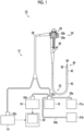
- Fig. 1 is a schematic configuration diagram showing an example of an ultrasonography system 10 that uses an ultrasonic endoscope 12 of the embodiment.
- the ultrasonography system 10 comprises the ultrasonic endoscope 12, an ultrasound processor device 14 that generates an ultrasound image, an endoscope processor device 16 that generates an endoscope image, a light source device 18 that supplies illumination light, with which the inside of a body cavity is illuminated, to the ultrasonic endoscope 12, and a monitor 20 that displays the ultrasound image and the endoscope image.
- the ultrasonography system 10 comprises a water supply tank 21a that stores cleaning water or the like, and a suction pump 21b that sucks aspirates inside the body cavity.
- the ultrasonic endoscope 12 has an insertion part 22 that is inserted into a body cavity of a subject, an operating part 24 that is consecutively provided in a proximal end part of the insertion part 22 and is used by an operator to perform an operation, a universal cord 26 that has one end connected to the operating part 24, and a distal end part 40 of the insertion part 22 comprises an ultrasonic observation part 36 and an endoscope observation part 38 described below.
- an air and water supply button 28a that opens and closes an air and water supply pipe line (not shown) from the water supply tank 21a, and a suction button 28b that opens and closes a suction pipe line (not shown) from the suction pump 21b are provided sequentially.
- a pair of angle knobs 29 and 29 and a treatment tool insertion port 30 are provided.
- an ultrasound connector 32a that is connected to the ultrasound processor device 14, an endoscope connector 32b that is connected to the endoscope processor device 16, and a light source connector 32c that is connected to the light source device 18 are provided.
- the ultrasonic endoscope 12 is attachably and detachably connected to the ultrasound processor device 14, the endoscope processor device 16, and the light source device 18 respectively through the connectors 32a, 32b, and 32c.
- the connector 32c comprises an air and water supply tube 34a that is connected to the water supply tank 21a, and a suction tube 34b that is connected to the suction pump 21b.
- the insertion part 22 has, in order from a distal end side, the distal end part 40 that has the ultrasonic observation part 36 and the endoscope observation part 38, a bendable part 42 that is consecutively provided on a proximal end side of the distal end part 40, and a soft part 43 that couples a proximal end side of the bendable part 42 and the distal end side of the operating part 24.
- the bendable part 42 is remotely bent and operated by rotationally moving and operating a pair of angle knobs 29 and 29 provided in the operating part 24. With this, the distal end part 40 can be directed in a desired direction.
- the ultrasound processor device 14 generates and supplies an ultrasound signal for making an ultrasonic oscillator array 50 of an ultrasonic oscillator unit 46 (see Fig. 2 ) of the ultrasonic observation part 36 described below generate an ultrasonic wave.
- the ultrasound processor device 14 receives and acquires an echo signal reflected from an observation target part irradiated with the ultrasonic wave, by the ultrasonic oscillator array 50 and executes various kinds of signal processing on the acquired echo signal to generate an ultrasound image that is displayed on the monitor 20.
- the endoscope processor device 16 receives and acquires a captured image signal acquired from the observation target part illuminated with illumination light from the light source device 18 in the endoscope observation part 38 and execute various kinds of signal processing and image processing on the acquired image signal to generate an endoscope image that is displayed on the monitor 20.
- the light source device 18 To image an observation target part inside a body cavity using the endoscope observation part 38 to acquire an image signal, the light source device 18 generates illumination light, such as white light including light of three primary colors of red light, green light, and blue light or light of a specific wavelength. Light propagates through a light guide (not shown) and the like in the ultrasonic endoscope 12, and is emitted from the endoscope observation part 38, and the observation target part inside the body cavity is illuminated with light.
- illumination light such as white light including light of three primary colors of red light, green light, and blue light or light of a specific wavelength.
- Light propagates through a light guide (not shown) and the like in the ultrasonic endoscope 12, and is emitted from the endoscope observation part 38, and the observation target part inside the body cavity is illuminated with light.
- the monitor 20 receives video signals generated by the ultrasound processor device 14 and the endoscope processor device 16 and displays an ultrasound image and an endoscope image.
- the display of the ultrasound image and the endoscope image only one image may be appropriately switched and displayed on the monitor 20 or both images may be displayed simultaneously.
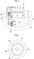
- Fig. 2 is a partial enlarged plan view showing the distal end part 40 shown in Fig. 1 and the vicinity thereof the distal end part 40.
- Fig. 3 is a sectional view taken along the line III-III shown in Fig. 2 , and is a longitudinal sectional view of the distal end part 40 taken along a center line thereof in a longitudinal direction.
- Fig. 4 is a sectional view taken along the line IV-IV shown in Fig. 3 , and is a cross-sectional view of the ultrasonic oscillator array 50 of the ultrasonic observation part 36 of the distal end part 40 taken along a center line of an arc structure.
- the ultrasonic observation part 36 that acquires the ultrasound image is mounted on the distal end side
- the endoscope observation part 38 that acquires the endoscope image is mounted on the proximal end side
- a treatment tool outlet port 44 is provided between the ultrasonic observation part 36 and the endoscope observation part 38.
- the endoscope observation part 38 is configured with an observation window 82, an objective lens 84, a solid-state imaging element 86, illumination windows 88, a cleaning nozzle 90, a wiring cable 92 including a plurality of coaxial cables (not shown), and the like.
- the treatment tool outlet port 44 is connected to a treatment tool channel 45 that is inserted into the insertion part 22, and a treatment tool (not shown) that is inserted from the treatment tool insertion port 30 of Fig. 1 is led out from the treatment tool outlet port 44 into the body cavity through the treatment tool channel 45.
- the ultrasonic observation part 36 comprises the ultrasonic oscillator unit 46, an exterior member 41 that holds the ultrasonic oscillator unit 46, and a plurality of coaxial cables 56 that are wired in the ultrasonic oscillator unit 46.
- the exterior member 41 is made of a rigid member, such as rigid resin, and configures a part of the distal end part 40.
- the ultrasonic oscillator unit 46 has the ultrasonic oscillator array 50 that includes a plurality of ultrasonic oscillators 48, an electrode 52 that is provided on an end portion side of the ultrasonic oscillator array 50 in a width direction (a direction perpendicular to the longitudinal axis direction of the insertion part 22), a backing material layer 54 that supports each ultrasonic oscillator 48 from a lower surface side, an FPC 60 that is disposed along a side surface of the backing material layer 54 in the width direction and is connected to the electrode 52, and a filler layer 80 as a second resin layer with which an internal space 55 between the exterior member 41 and the backing material layer 54 is filled.
- the ultrasonic oscillator unit 46 has an acoustic matching layer 76 laminated on the ultrasonic oscillator array 50, and an acoustic lens 78 laminated on the acoustic matching layer 76. That is, the ultrasonic oscillator unit 46 is configured as a laminate 47 having the acoustic lens 78, the acoustic matching layer 76, the ultrasonic oscillator array 50, and the backing material layer 54.
- the ultrasonic oscillator array 50 is configured with a plurality of rectangular parallelepiped ultrasonic oscillators 48 arranged in a convex arc shape outward.
- the ultrasonic oscillator array 50 is an array of 48 to 192 channels consisting of 48 to 192 ultrasonic oscillators 48, for example.
- Each of the ultrasonic oscillators 48 has a piezoelectric body 49.
- the ultrasonic oscillator array 50 of the present example is configured by arranging a plurality of ultrasonic oscillators 48 at predetermined pitches in a one-dimensional array shape as an example.
- the ultrasonic oscillators 48 that configure the ultrasonic oscillator array 50 are arranged at regular intervals in a convex bent shape along an axial direction of the distal end part 40 (the longitudinal axis direction of the insertion part 22) and are sequentially driven based on drive signals input from the ultrasound processor device 14 (see Fig. 1 ). With this, convex electronic scanning is performed with a range where the ultrasonic oscillators 48 shown in Fig. 2 are arranged, as a scanning range.
- the electrode 52 of the ultrasonic oscillator array 50 has an individual electrode 52a individually and independently provided for each ultrasonic oscillator 48, and an oscillator ground 52b that is a common electrode common to all the ultrasonic oscillators 48.
- a plurality of individual electrodes 52a are disposed on lower surfaces of end portions of a plurality of ultrasonic oscillators 48, and the oscillator ground 52b is provided on upper surfaces of the end portions of the ultrasonic oscillators 48.
- the acoustic matching layer 76 is a layer that is provided for taking acoustic impedance matching between the subject and the ultrasonic oscillators 48.
- the acoustic lens 78 is a lens that is provided for converging the ultrasonic waves emitted from the ultrasonic oscillator array 50 toward the observation target part.
- powder such as titanium oxide, alumina, or silica
- the acoustic lens 78 is formed of, for example, silicon-based resin (millable type silicon rubber, liquid silicon rubber, or the lie), butadiene-based resin, or polyurethane-based resin.
- the backing material layer 54 is a layer of a member made of a backing material disposed on an inside with respect to the arrangement surface of a plurality of ultrasonic oscillators 48, that is, a rear surface (lower surface) of the ultrasonic oscillator array 50.
- the backing material layer 54 has a role of mechanically and flexibly supporting the ultrasonic oscillator array 50 and attenuating ultrasonic waves propagated to the backing material layer 54 side among ultrasound signals oscillated from a plurality of ultrasonic oscillators 48 or reflected and propagated from the observation target.
- the backing material is made of a material having rigidity, such as hard rubber, and an ultrasonic wave attenuation material (ferrite, ceramics, or the like) is added as needed.
- the filler layer 80 is a layer with which the internal space 55 between the exterior member 41 and the backing material layer 54 is filled, and has a role of fixing the FPC 60, the coaxial cables 56, and various wiring portions. It is preferable that the acoustic impedance of the filler layer 80 matches the acoustic impedance of the backing material layer 54 with given accuracy or higher such that the ultrasound signals propagated from the ultrasonic oscillator array 50 to the backing material layer 54 side are not reflected at a boundary surface between the filler layer 80 and the backing material layer 54. It is preferable that the filler layer 80 is made of a member having heat dissipation to increase efficiency in dissipating heat generated in a plurality of ultrasonic oscillators 48. In a case where the filler layer 80 has heat dissipation, since heat is received from the backing material layer 54, the FPC 60, the coaxial cables 56, and the like, heat dissipation efficiency can be improved.
- each ultrasonic oscillator 48 of the ultrasonic oscillator array 50 is driven, and a voltage is applied to the electrode 52 of the ultrasonic oscillator 48, the piezoelectric body 49 oscillates to sequentially generate ultrasonic waves, and the irradiation of the ultrasonic waves is performed toward the observation target part of the subject.
- ultrasonic oscillators 48 are sequentially driven by an electronic switch, such as a multiplexer, scanning with ultrasonic waves is performed in a scanning range along a curved surface on which the ultrasonic oscillator array 50 is disposed, for example, a range of about several tens mm from the center of curvature of the curved surface.
- the piezoelectric body 49 vibrates to generate a voltage and outputs the voltage as an electric signal corresponding to the received ultrasound echo to the ultrasound processor device 14. Then, the electric signal is subjected to various kinds of signal processing in the ultrasound processor device 14 and is displayed as an ultrasound image on the monitor 20.
- the FPC 60 shown in Fig. 4 has a plurality of electrode pads 62 that are electrically connected to a plurality of individual electrode 52a at one end, and a plurality of electrode pads 64 that are electrically connected to a plurality of signal lines 56a of the coaxial cable 56 at the other end.
- the FPC 60 also has a ground portion (not shown) that is electrically connected to the oscillator ground 52b.
- each coaxial cable 56 comprises a signal line 56a connected to the electrode pad 64 on a center side, and has an insulating outer coat 56b provided in a layer outside the signal line 56a, a shield layer 56c provided in a layer outside the outer coat 56b, and an insulating outer coat 56d provided in an outermost layer.
- an electrical bonded portion 100 of the electrode pad 62 and the individual electrode 52a is bonded by a conductive resin material 102, and an electrical bonded portion 104 of the electrode pad 64 and the signal line 56a is also boned by the conductive resin material 102.
- Examples of the above-described resin material 102 include an anisotropic conductive film (ACF) or an anisotropic conductive paste (ACP) obtained by mixing thermosetting resin with fine conductive particles and forming the mixture into a film.
- ACF anisotropic conductive film
- ACP anisotropic conductive paste
- the electrical bonded portions 100 and 104 bonded by such a resin material 102 may be deteriorated and disconnected due to contact with sterilizing gas, such as ethylene oxide gas or hydrogen peroxide plasma gas, in a case where the ultrasonic endoscope 12 is cleaned by a gas sterilization device.
- each of the electrical bonded portions 100 and 104 is coated with a low reactive epoxy resin layer 106 that is a first resin layer. Then, even though the above-described sterilizing gas is transmitted through the acoustic lens 78 or the filler layer 80 and enters the electrical bonded portions 100 and 104 side, since the above-described epoxy resin layer 106 exhibits a function as a gas barrier, it is possible to suppress contact of the sterilizing gas with the electrical bonded portions 100 and 104. With this, it is possible to suppress deterioration of the electrical bonded portions 100 and 104 due to the sterilizing gas.
- the ultrasonic endoscope 12 of the embodiment since the electrical bonded portions 100 and 104 from the coaxial cable 56 to the piezoelectric body 49 are bonded by the conductive resin material 102, and the electrical bonded portions 100 and 104 using the resin material 102 are coated with the gas barrier epoxy resin layer 106, it is possible to suppress deterioration of the electrical bonded portions 100 and 104 due to the sterilizing gas.
- the present invention is not limited thereto, at least the electrical bonded portions 100 and 104 that are bonded by the conductive resin material 102 may be coated with the epoxy resin layer 106.
- connection structure to which the present example is applied is not limited thereto.
- the present example can be applied to a first another connection structure in which the piezoelectric bodies 49 and the coaxial cables 56 are connected through electrical bonded portions, and a second another connection structure in which a first FPC connected to the piezoelectric bodies 49 and a second FPC connected to the coaxial cables 56 are connected through electrical bonded portions.
- the electrical bonded portions are coated with the epoxy resin layer 106 in advance. With this, since mechanical strength of the electrical bonded portions is improved, it is possible to restrain the electrical bonded portions from being damaged at the time of handling during manufacturing.
- the resin material 102 is the ACF
- the present invention is not limited thereto.
- a resin material in which a conductive filler, such as metallic particles, is dispersed into binder resin, such as epoxy or urethane, and the conductive filler forms a conductive path after adhesion may be used.
- this resin material include a conductive paste, such as a silver paste.
- the epoxy resin of the epoxy resin layer 106 has a polyoxyalkylene structure. With this, gas resistance of the epoxy resin layer 106 to the sterilizing gas is improved.
- the epoxy resin of the epoxy resin layer 106 contains an alcohol compound. With this, gas resistance of the epoxy resin layer 106 to the sterilizing gas is improved. In this case, it is more preferable that a hydroxyl group equivalent of the alcohol compound is equal to or greater than 25 and equal to or less than 150, and a molecular weight of the alcohol compound is equal to or greater than 50 and equal to or less than 500. With this, it is possible to obtain the same gas resistance as the above-described polyoxyalkylene structure.
- the epoxy resin of the epoxy resin layer 106 has a polyamide structure. With this, gas resistance of the epoxy resin layer 106 to the sterilizing gas is improved.
- second resin for forming the filler layer 80 is epoxy resin, and it is more preferable that the epoxy resin has a polyamide structure. With this, it is possible to allow the filler layer 80 to have gas resistance.
- epoxy resin having high gas resistance (that is, low responsiveness to gas) has a large molecular weight and high viscosity. From such situations, it is preferable that epoxy resin having high viscosity before curing to some extent is employed as the first resin layer with which the electrical bonded portions 100 and 104 are coated. With this, it is possible to increase gas resistance, and to reliably coat the electrical bonded portions 100 and 104.
- epoxy resin having lower viscosity before curing than the first resin is employed as the second resin for forming the filler layer 80.
- the second resin since it is possible to spread the second resin over the entire region of the internal space 55, it is possible to suppress the occurrence of air bubbles that cause gas transmission, in the filler layer 80.
- the viscosity before curing of the first resin layer is equal to or greater than 50 Pa s and equal to or less than 500 Pa s as an example.
- the viscosity before curing of the second resin layer is preferably equal to or greater than 1 Pa ⁇ s and equal to or less than 30 Pa s, and is more preferably equal to or greater than 1 Pa ⁇ s and equal to or less than 15 Pa s.
- the ultrasonic endoscope is inserted into a human body, there is a need for a reduction in diameter of the insertion part.
- the cable that is connected to the ultrasonic oscillator is very fine compared to a cable that is used in a body surface echo.
- mechanical strength of the electrical bonded portions is very weak, and the electrical bonded portions are easily damaged at the time of handling during manufacturing.
- a load is applied to the cable at the time of work of storing the ultrasonic oscillator in the distal end part, there is a high possibility that the electrical bonded portions are damaged.
- solder instead of a conductive resin material, is used in bonding for a small ultrasonic oscillator that is employed in the ultrasonic endoscope, and in a case where heat equal to or higher than 100 degrees is transmitted to the piezoelectric body, the piezoelectric body has an increased risk of being damaged due to the occurrence of microcracks in the piezoelectric body.
- a disposition interval of the electrode pads of the FPC is narrow and bonding work is impossible with solder, and a solder defect is likely to occur. For this reason, a place where bonding needs to be performed using a conductive resin material necessarily occurs.
- the ultrasonic endoscope 12 of the embodiment since the electrical bonded portions 100 and 104 are coated with the epoxy resin layer 106, mechanical strength of the electrical bonded portions 100 and 104 is improved. With this, the ultrasonic endoscope 12 of the embodiment solves the problem that the electrical bonded portions 100 and 104 are easily damaged at the time of handling during manufacturing.
Landscapes
- Physics & Mathematics (AREA)
- Engineering & Computer Science (AREA)
- Acoustics & Sound (AREA)
- Multimedia (AREA)
- Health & Medical Sciences (AREA)
- Life Sciences & Earth Sciences (AREA)
- Mechanical Engineering (AREA)
- Optics & Photonics (AREA)
- General Physics & Mathematics (AREA)
- Astronomy & Astrophysics (AREA)
- Medical Informatics (AREA)
- Public Health (AREA)
- Biomedical Technology (AREA)
- Molecular Biology (AREA)
- Surgery (AREA)
- Animal Behavior & Ethology (AREA)
- General Health & Medical Sciences (AREA)
- Heart & Thoracic Surgery (AREA)
- Veterinary Medicine (AREA)
- Radiology & Medical Imaging (AREA)
- Pathology (AREA)
- Nuclear Medicine, Radiotherapy & Molecular Imaging (AREA)
- Biophysics (AREA)
- Ultra Sonic Daignosis Equipment (AREA)
Abstract
Description
- The present invention relates to an ultrasonic oscillator unit and an ultrasonic endoscope.
- In recent years, an ultrasonic endoscope that observes a state inside a body of a subject by irradiating the inside of the body with ultrasonic waves and receives reflected waves to capture video has been used in medical practice.
- In such an ultrasonic endoscope, for example, as disclosed in
WO2018/003322A , an ultrasonic oscillator unit is provided in a distal end part of an insertion part that is inserted into a body. In general, the ultrasonic oscillator unit has an ultrasonic oscillator array including a plurality of ultrasonic oscillators (transducers), and the ultrasonic oscillator array is held while being attached to an exterior member provided in the distal end part. -
WO2018/003322A discloses a connection structure that electrically connects electrode pads of the ultrasonic oscillators and electrode pads of a flexible printed wiring board (hereinafter, simply referred to as a flexible printed circuit (FPC)) by solder wires or conductive paste (for example, silver paste). Other ends of a plurality of coaxial cables having one ends connected to an ultrasound processor device are electrically connected to the above-described FPC. - Note that, in the connection structure using soldering out of the above-described connection structures, in a case where heat of soldering in providing the solder wires is transmitted to the ultrasonic oscillators, microcracks may occur in the ultrasonic oscillators due to heat. The microcracks cause degradation of quality of an ultrasound image, and it is not preferred. On the other hand, the connection structure using conductive paste can solve a heat problem by soldering, but has the following problem.
- That is, the ultrasonic endoscope is put into, for example, a sterilizing tank of a gas sterilization device and is cleaned after being used in an operation. In this case, the ultrasonic endoscope is cleaned through exposure to sterilizing gas, such as ethylene oxide gas or hydrogen peroxide plasma gas, under a reduced pressure atmosphere; however, sterilizing gas has a component that causes change in quality or deterioration of a member with which sterilizing gas is brought into contact. For this reason, in a case where the ultrasonic oscillator unit is cleaned by sterilizing gas many times, an electrical bonded portion formed of, for example, conductive paste may be deteriorated and disconnection may occur.
- The present invention has been accomplished in view of such a situation, and an object of the present invention is to provide an ultrasonic oscillator unit and an ultrasonic endoscope capable of suppressing deterioration of an electrical bonded portion due to sterilizing gas.
- To achieve the object of the present invention, there is provided an ultrasonic oscillator unit of the present invention that is disposed in a distal end part of an endoscope insertion part and has a plurality of ultrasonic oscillators, in which the ultrasonic oscillators each have a piezoelectric body, a cable that is electrically bonded to the piezoelectric body is inserted into an internal space of the distal end part, at least one of a plurality of electrical bonded portions from the cable to the piezoelectric body is bonded by a resin material having conductivity (conductive resin material), the electrical bonded portion using the resin material is covered with a first resin layer, and first resin is gas barrier epoxy resin.
- In an aspect of the present invention, it is preferable that the epoxy resin has a polyoxyalkylene structure.
- In an aspect of the present invention, it is preferable that the epoxy resin contains an alcohol compound.
- In an aspect of the present invention, it is preferable that a hydroxyl group equivalent of the alcohol compound is equal to or greater than 25 and equal to or less than 150, and a molecular weight of the alcohol compound is equal to or greater than 50 and equal to or less than 500.
- In an aspect of the present invention, it is preferable that the epoxy resin has a polyamide structure.
- In an aspect of the present invention, it is preferable that the internal space of the distal end part into which the cable is inserted is filled with a second resin layer, and second resin is epoxy resin.
- In an aspect of the present invention, it is preferable that the epoxy resin has a polyamide structure.
- In an aspect of the present invention, it is preferable that the first resin layer has higher viscosity before curing than the second resin layer.
- To achieve the object of the present invention, there is provided an ultrasonic endoscope of the present invention having an insertion part that is inserted into a body, an ultrasonic observation part that is provided at a distal end of the insertion part, and the ultrasonic oscillator unit of the present invention provided in the ultrasonic observation part.
- According to the present invention, it is possible to suppress deterioration of an electrical bonded portion due to sterilizing gas.
-
-
Fig. 1 is a schematic configuration diagram showing an example of the configuration of an ultrasonography system. -
Fig. 2 is a partial enlarged plan view showing adistal end part 40 of an ultrasonic endoscope ofFig. 1 and the vicinity of the distal end part. -
Fig. 3 is a sectional view taken along the line III-III ofFig. 2 . -
Fig. 4 is a sectional view taken along the line IV-IV ofFig. 3 . -
Fig. 5 is a sectional view of a coaxial cable. - Hereinafter, a preferred embodiment of an ultrasonic oscillator unit and an ultrasonic endoscope according to the present invention will be described referring to the accompanying drawings.
-
Fig. 1 is a schematic configuration diagram showing an example of anultrasonography system 10 that uses anultrasonic endoscope 12 of the embodiment. - As shown in
Fig. 1 , theultrasonography system 10 comprises theultrasonic endoscope 12, anultrasound processor device 14 that generates an ultrasound image, anendoscope processor device 16 that generates an endoscope image, alight source device 18 that supplies illumination light, with which the inside of a body cavity is illuminated, to theultrasonic endoscope 12, and amonitor 20 that displays the ultrasound image and the endoscope image. Theultrasonography system 10 comprises awater supply tank 21a that stores cleaning water or the like, and asuction pump 21b that sucks aspirates inside the body cavity. - The
ultrasonic endoscope 12 has aninsertion part 22 that is inserted into a body cavity of a subject, anoperating part 24 that is consecutively provided in a proximal end part of theinsertion part 22 and is used by an operator to perform an operation, auniversal cord 26 that has one end connected to theoperating part 24, and adistal end part 40 of theinsertion part 22 comprises anultrasonic observation part 36 and anendoscope observation part 38 described below. - In the
operating part 24, an air andwater supply button 28a that opens and closes an air and water supply pipe line (not shown) from thewater supply tank 21a, and asuction button 28b that opens and closes a suction pipe line (not shown) from thesuction pump 21b are provided sequentially. In theoperating part 24, a pair ofangle knobs tool insertion port 30 are provided. - In the other end portion of the
universal cord 26, anultrasound connector 32a that is connected to theultrasound processor device 14, anendoscope connector 32b that is connected to theendoscope processor device 16, and alight source connector 32c that is connected to thelight source device 18 are provided. Theultrasonic endoscope 12 is attachably and detachably connected to theultrasound processor device 14, theendoscope processor device 16, and thelight source device 18 respectively through theconnectors connector 32c comprises an air andwater supply tube 34a that is connected to thewater supply tank 21a, and asuction tube 34b that is connected to thesuction pump 21b. - The
insertion part 22 has, in order from a distal end side, thedistal end part 40 that has theultrasonic observation part 36 and theendoscope observation part 38, abendable part 42 that is consecutively provided on a proximal end side of thedistal end part 40, and asoft part 43 that couples a proximal end side of thebendable part 42 and the distal end side of theoperating part 24. - The
bendable part 42 is remotely bent and operated by rotationally moving and operating a pair ofangle knobs operating part 24. With this, thedistal end part 40 can be directed in a desired direction. - The
ultrasound processor device 14 generates and supplies an ultrasound signal for making anultrasonic oscillator array 50 of an ultrasonic oscillator unit 46 (seeFig. 2 ) of theultrasonic observation part 36 described below generate an ultrasonic wave. Theultrasound processor device 14 receives and acquires an echo signal reflected from an observation target part irradiated with the ultrasonic wave, by theultrasonic oscillator array 50 and executes various kinds of signal processing on the acquired echo signal to generate an ultrasound image that is displayed on themonitor 20. - The
endoscope processor device 16 receives and acquires a captured image signal acquired from the observation target part illuminated with illumination light from thelight source device 18 in theendoscope observation part 38 and execute various kinds of signal processing and image processing on the acquired image signal to generate an endoscope image that is displayed on themonitor 20. - To image an observation target part inside a body cavity using the
endoscope observation part 38 to acquire an image signal, thelight source device 18 generates illumination light, such as white light including light of three primary colors of red light, green light, and blue light or light of a specific wavelength. Light propagates through a light guide (not shown) and the like in theultrasonic endoscope 12, and is emitted from theendoscope observation part 38, and the observation target part inside the body cavity is illuminated with light. - The
monitor 20 receives video signals generated by theultrasound processor device 14 and theendoscope processor device 16 and displays an ultrasound image and an endoscope image. In regard to the display of the ultrasound image and the endoscope image, only one image may be appropriately switched and displayed on themonitor 20 or both images may be displayed simultaneously. - Next, the configuration of the
distal end part 40 will be described referring toFigs. 2 to 4 . -
Fig. 2 is a partial enlarged plan view showing thedistal end part 40 shown inFig. 1 and the vicinity thereof thedistal end part 40.Fig. 3 is a sectional view taken along the line III-III shown inFig. 2 , and is a longitudinal sectional view of thedistal end part 40 taken along a center line thereof in a longitudinal direction.Fig. 4 is a sectional view taken along the line IV-IV shown inFig. 3 , and is a cross-sectional view of theultrasonic oscillator array 50 of theultrasonic observation part 36 of thedistal end part 40 taken along a center line of an arc structure. - As shown in
Figs. 2 and3 , in thedistal end part 40, theultrasonic observation part 36 that acquires the ultrasound image is mounted on the distal end side, theendoscope observation part 38 that acquires the endoscope image is mounted on the proximal end side, and a treatmenttool outlet port 44 is provided between theultrasonic observation part 36 and theendoscope observation part 38. - The
endoscope observation part 38 is configured with anobservation window 82, anobjective lens 84, a solid-state imaging element 86,illumination windows 88, acleaning nozzle 90, awiring cable 92 including a plurality of coaxial cables (not shown), and the like. - The treatment
tool outlet port 44 is connected to atreatment tool channel 45 that is inserted into theinsertion part 22, and a treatment tool (not shown) that is inserted from the treatmenttool insertion port 30 ofFig. 1 is led out from the treatmenttool outlet port 44 into the body cavity through thetreatment tool channel 45. - As shown in
Figs. 2 to 4 , theultrasonic observation part 36 comprises theultrasonic oscillator unit 46, anexterior member 41 that holds theultrasonic oscillator unit 46, and a plurality ofcoaxial cables 56 that are wired in theultrasonic oscillator unit 46. Theexterior member 41 is made of a rigid member, such as rigid resin, and configures a part of thedistal end part 40. - The
ultrasonic oscillator unit 46 has theultrasonic oscillator array 50 that includes a plurality ofultrasonic oscillators 48, anelectrode 52 that is provided on an end portion side of theultrasonic oscillator array 50 in a width direction (a direction perpendicular to the longitudinal axis direction of the insertion part 22), abacking material layer 54 that supports eachultrasonic oscillator 48 from a lower surface side, anFPC 60 that is disposed along a side surface of thebacking material layer 54 in the width direction and is connected to theelectrode 52, and afiller layer 80 as a second resin layer with which an internal space 55 between theexterior member 41 and thebacking material layer 54 is filled. - The
ultrasonic oscillator unit 46 has anacoustic matching layer 76 laminated on theultrasonic oscillator array 50, and anacoustic lens 78 laminated on theacoustic matching layer 76. That is, theultrasonic oscillator unit 46 is configured as a laminate 47 having theacoustic lens 78, theacoustic matching layer 76, theultrasonic oscillator array 50, and thebacking material layer 54. - The
ultrasonic oscillator array 50 is configured with a plurality of rectangular parallelepipedultrasonic oscillators 48 arranged in a convex arc shape outward. Theultrasonic oscillator array 50 is an array of 48 to 192 channels consisting of 48 to 192ultrasonic oscillators 48, for example. Each of theultrasonic oscillators 48 has apiezoelectric body 49. - The
ultrasonic oscillator array 50 of the present example is configured by arranging a plurality ofultrasonic oscillators 48 at predetermined pitches in a one-dimensional array shape as an example. Theultrasonic oscillators 48 that configure theultrasonic oscillator array 50 are arranged at regular intervals in a convex bent shape along an axial direction of the distal end part 40 (the longitudinal axis direction of the insertion part 22) and are sequentially driven based on drive signals input from the ultrasound processor device 14 (seeFig. 1 ). With this, convex electronic scanning is performed with a range where theultrasonic oscillators 48 shown inFig. 2 are arranged, as a scanning range. - The
electrode 52 of theultrasonic oscillator array 50 has anindividual electrode 52a individually and independently provided for eachultrasonic oscillator 48, and anoscillator ground 52b that is a common electrode common to all theultrasonic oscillators 48. InFig. 4 , a plurality ofindividual electrodes 52a are disposed on lower surfaces of end portions of a plurality ofultrasonic oscillators 48, and theoscillator ground 52b is provided on upper surfaces of the end portions of theultrasonic oscillators 48. - The
acoustic matching layer 76 is a layer that is provided for taking acoustic impedance matching between the subject and theultrasonic oscillators 48. - The
acoustic lens 78 is a lens that is provided for converging the ultrasonic waves emitted from theultrasonic oscillator array 50 toward the observation target part. In theacoustic lens 78, powder, such as titanium oxide, alumina, or silica, is mixed as necessary to take acoustic impedance matching between the subject and theultrasonic oscillators 48 in theacoustic matching layer 76, and to increase the transmittance of the ultrasonic waves. Theacoustic lens 78 is formed of, for example, silicon-based resin (millable type silicon rubber, liquid silicon rubber, or the lie), butadiene-based resin, or polyurethane-based resin. - As shown in
Figs. 3 and4 , thebacking material layer 54 is a layer of a member made of a backing material disposed on an inside with respect to the arrangement surface of a plurality ofultrasonic oscillators 48, that is, a rear surface (lower surface) of theultrasonic oscillator array 50. Thebacking material layer 54 has a role of mechanically and flexibly supporting theultrasonic oscillator array 50 and attenuating ultrasonic waves propagated to thebacking material layer 54 side among ultrasound signals oscillated from a plurality ofultrasonic oscillators 48 or reflected and propagated from the observation target. For this reason, the backing material is made of a material having rigidity, such as hard rubber, and an ultrasonic wave attenuation material (ferrite, ceramics, or the like) is added as needed. - The
filler layer 80 is a layer with which the internal space 55 between theexterior member 41 and thebacking material layer 54 is filled, and has a role of fixing theFPC 60, thecoaxial cables 56, and various wiring portions. It is preferable that the acoustic impedance of thefiller layer 80 matches the acoustic impedance of thebacking material layer 54 with given accuracy or higher such that the ultrasound signals propagated from theultrasonic oscillator array 50 to thebacking material layer 54 side are not reflected at a boundary surface between thefiller layer 80 and thebacking material layer 54. It is preferable that thefiller layer 80 is made of a member having heat dissipation to increase efficiency in dissipating heat generated in a plurality ofultrasonic oscillators 48. In a case where thefiller layer 80 has heat dissipation, since heat is received from thebacking material layer 54, theFPC 60, thecoaxial cables 56, and the like, heat dissipation efficiency can be improved. - With the
ultrasonic oscillator unit 46 configured as described above, in a case where eachultrasonic oscillator 48 of theultrasonic oscillator array 50 is driven, and a voltage is applied to theelectrode 52 of theultrasonic oscillator 48, thepiezoelectric body 49 oscillates to sequentially generate ultrasonic waves, and the irradiation of the ultrasonic waves is performed toward the observation target part of the subject. Then, as a plurality ofultrasonic oscillators 48 are sequentially driven by an electronic switch, such as a multiplexer, scanning with ultrasonic waves is performed in a scanning range along a curved surface on which theultrasonic oscillator array 50 is disposed, for example, a range of about several tens mm from the center of curvature of the curved surface. - In a case where the echo signal reflected from the observation target part is received, the
piezoelectric body 49 vibrates to generate a voltage and outputs the voltage as an electric signal corresponding to the received ultrasound echo to theultrasound processor device 14. Then, the electric signal is subjected to various kinds of signal processing in theultrasound processor device 14 and is displayed as an ultrasound image on themonitor 20. - By the way, the
FPC 60 shown inFig. 4 has a plurality ofelectrode pads 62 that are electrically connected to a plurality ofindividual electrode 52a at one end, and a plurality ofelectrode pads 64 that are electrically connected to a plurality ofsignal lines 56a of thecoaxial cable 56 at the other end. TheFPC 60 also has a ground portion (not shown) that is electrically connected to theoscillator ground 52b. - Here, as shown in
Fig. 3 , thecoaxial cables 56 of the present example are bundled using anouter coat 58 on the proximal end side of thedistal end part 40, and are led out from theouter coat 58 and are connected to theFPC 60 at the time of wiring. As shown in a sectional view ofFig. 5 , eachcoaxial cable 56 comprises asignal line 56a connected to theelectrode pad 64 on a center side, and has an insulatingouter coat 56b provided in a layer outside thesignal line 56a, ashield layer 56c provided in a layer outside theouter coat 56b, and an insulatingouter coat 56d provided in an outermost layer. - Returning to
Fig. 4 , an electrical bondedportion 100 of theelectrode pad 62 and theindividual electrode 52a is bonded by aconductive resin material 102, and an electrical bondedportion 104 of theelectrode pad 64 and thesignal line 56a is also boned by theconductive resin material 102. - Examples of the above-described
resin material 102 include an anisotropic conductive film (ACF) or an anisotropic conductive paste (ACP) obtained by mixing thermosetting resin with fine conductive particles and forming the mixture into a film. The electrical bondedportions resin material 102 may be deteriorated and disconnected due to contact with sterilizing gas, such as ethylene oxide gas or hydrogen peroxide plasma gas, in a case where theultrasonic endoscope 12 is cleaned by a gas sterilization device. - Accordingly, in the
ultrasonic endoscope 12 of the embodiment, as shown inFig. 4 , each of the electrical bondedportions epoxy resin layer 106 that is a first resin layer. Then, even though the above-described sterilizing gas is transmitted through theacoustic lens 78 or thefiller layer 80 and enters the electrical bondedportions epoxy resin layer 106 exhibits a function as a gas barrier, it is possible to suppress contact of the sterilizing gas with the electrical bondedportions portions - Accordingly, with the
ultrasonic endoscope 12 of the embodiment, since the electrical bondedportions coaxial cable 56 to thepiezoelectric body 49 are bonded by theconductive resin material 102, and the electrical bondedportions resin material 102 are coated with the gas barrierepoxy resin layer 106, it is possible to suppress deterioration of the electrical bondedportions - Although it is preferable that all electrical bonded portions from the
coaxial cable 56 to thepiezoelectric body 49 are coated with theepoxy resin layer 106, the present invention is not limited thereto, at least the electrical bondedportions conductive resin material 102 may be coated with theepoxy resin layer 106. - In the
ultrasonic endoscope 12 of the embodiment, although an aspect where the present example is applied to the connection structure in which thepiezoelectric bodies 49 and thecoaxial cables 56 are connected through theFPC 60 has been described, a connection structure to which the present example is applied is not limited thereto. For example, the present example can be applied to a first another connection structure in which thepiezoelectric bodies 49 and thecoaxial cables 56 are connected through electrical bonded portions, and a second another connection structure in which a first FPC connected to thepiezoelectric bodies 49 and a second FPC connected to thecoaxial cables 56 are connected through electrical bonded portions. In this case, in the second another connection structure, since stress is likely to be concentrated on the above-described electrical bonded portions at the time of handling during manufacturing, it is preferable that the electrical bonded portions are coated with theepoxy resin layer 106 in advance. With this, since mechanical strength of the electrical bonded portions is improved, it is possible to restrain the electrical bonded portions from being damaged at the time of handling during manufacturing. - In the
ultrasonic endoscope 12 of the embodiment, although theresin material 102 is the ACF, the present invention is not limited thereto. For example, a resin material in which a conductive filler, such as metallic particles, is dispersed into binder resin, such as epoxy or urethane, and the conductive filler forms a conductive path after adhesion may be used. Examples of this resin material include a conductive paste, such as a silver paste. - Hereinafter, a specific example of the
epoxy resin layer 106 will be described. - It is preferable that the epoxy resin of the
epoxy resin layer 106 has a polyoxyalkylene structure. With this, gas resistance of theepoxy resin layer 106 to the sterilizing gas is improved. - It is preferable that the epoxy resin of the
epoxy resin layer 106 contains an alcohol compound. With this, gas resistance of theepoxy resin layer 106 to the sterilizing gas is improved. In this case, it is more preferable that a hydroxyl group equivalent of the alcohol compound is equal to or greater than 25 and equal to or less than 150, and a molecular weight of the alcohol compound is equal to or greater than 50 and equal to or less than 500. With this, it is possible to obtain the same gas resistance as the above-described polyoxyalkylene structure. - It is preferable that the epoxy resin of the
epoxy resin layer 106 has a polyamide structure. With this, gas resistance of theepoxy resin layer 106 to the sterilizing gas is improved. - On the other hand, it is preferable that second resin for forming the
filler layer 80 is epoxy resin, and it is more preferable that the epoxy resin has a polyamide structure. With this, it is possible to allow thefiller layer 80 to have gas resistance. - Here, epoxy resin having high gas resistance (that is, low responsiveness to gas) has a large molecular weight and high viscosity. From such situations, it is preferable that epoxy resin having high viscosity before curing to some extent is employed as the first resin layer with which the electrical bonded
portions portions - It is preferable that epoxy resin having lower viscosity before curing than the first resin is employed as the second resin for forming the
filler layer 80. With this, since it is possible to spread the second resin over the entire region of the internal space 55, it is possible to suppress the occurrence of air bubbles that cause gas transmission, in thefiller layer 80. - It is preferable that the viscosity before curing of the first resin layer is equal to or greater than 50 Pa s and equal to or less than 500 Pa s as an example. The viscosity before curing of the second resin layer is preferably equal to or greater than 1 Pa·s and equal to or less than 30 Pa s, and is more preferably equal to or greater than 1 Pa·s and equal to or less than 15 Pa s.
- By the way, since the ultrasonic endoscope is inserted into a human body, there is a need for a reduction in diameter of the insertion part. To realize the reduction in diameter of the insertion part, the cable that is connected to the ultrasonic oscillator is very fine compared to a cable that is used in a body surface echo. As a result, there is a problem in that mechanical strength of the electrical bonded portions is very weak, and the electrical bonded portions are easily damaged at the time of handling during manufacturing. In particular, since a load is applied to the cable at the time of work of storing the ultrasonic oscillator in the distal end part, there is a high possibility that the electrical bonded portions are damaged.
- In a case where solder, instead of a conductive resin material, is used in bonding for a small ultrasonic oscillator that is employed in the ultrasonic endoscope, and in a case where heat equal to or higher than 100 degrees is transmitted to the piezoelectric body, the piezoelectric body has an increased risk of being damaged due to the occurrence of microcracks in the piezoelectric body. Alternatively, a disposition interval of the electrode pads of the FPC is narrow and bonding work is impossible with solder, and a solder defect is likely to occur. For this reason, a place where bonding needs to be performed using a conductive resin material necessarily occurs. In this case, since the conductive resin material has weak mechanical strength compared to solder, there is a higher possibility that the electrical bonded portions are damaged at the time of handling during manufacturing. In this way, an ultrasonic endoscope of the related art has a problem that the electrical bonded portions are easily damaged at the time of handling during manufacturing.
- In contrast, in the
ultrasonic endoscope 12 of the embodiment, since the electrical bondedportions epoxy resin layer 106, mechanical strength of the electrical bondedportions ultrasonic endoscope 12 of the embodiment solves the problem that the electrical bondedportions - Although the present invention has been described, the present invention is not limited to the above-described example, and various improvements or modifications may be of course made without departing from the spirit and scope of the present invention.
-
- 10: ultrasonography system
- 12: ultrasonic endoscope
- 14: ultrasound processor device
- 16: endoscope processor device
- 18: light source device
- 20: monitor
- 21a: water supply tank
- 21b: suction pump
- 22: insertion part
- 24: operating part
- 26: universal cord
- 29: angle knob
- 30: treatment tool insertion port
- 32a: connector
- 32b: connector
- 32c: connector
- 34a: air and water supply tube
- 34b: suction tube
- 36: ultrasonic observation part
- 38: endoscope observation part
- 40: distal end part
- 41: exterior member
- 42: bendable part
- 43: soft part
- 44: treatment tool outlet port
- 45: treatment tool channel
- 46: ultrasonic oscillator unit
- 48: ultrasonic oscillator
- 49: piezoelectric body
- 50: ultrasonic oscillator array
- 52: electrode
- 52a: individual electrode
- 52b: oscillator ground
- 54: backing material layer
- 55: internal space
- 56: coaxial cable
- 56a: signal line
- 56b: outer coat
- 56c: shield layer
- 56d: outer coat
- 58: outer coat
- 60: FPC
- 62: electrode pad
- 64: electrode pad
- 76: acoustic matching layer
- 78: acoustic lens
- 80: filler layer
- 82: observation window
- 84: objective lens
- 86: solid-state imaging element
- 88: illumination window
- 90: cleaning nozzle
- 92: wiring cable
- 100: electrical bonded portion
- 102: resin material
- 104: electrical bonded portion
- 106: epoxy resin layer
Claims (9)
- An ultrasonic oscillator unit that is disposed in a distal end part of an endoscope insertion part and has a plurality of ultrasonic oscillators,wherein the ultrasonic oscillators each have a piezoelectric body,a cable that is electrically bonded to the piezoelectric body is inserted into an internal space of the distal end part,at least one of a plurality of electrical bonded portions from the cable to the piezoelectric body is bonded by a resin material having conductivity,the electrical bonded portion using the resin material is covered with a first resin layer, andfirst resin is gas barrier epoxy resin.
- The ultrasonic oscillator unit according to claim 1,
wherein the epoxy resin has a polyoxyalkylene structure. - The ultrasonic oscillator unit according to claim 1 or 2,
wherein the epoxy resin contains an alcohol compound. - The ultrasonic oscillator unit according to claim 3,
wherein a hydroxyl group equivalent of the alcohol compound is equal to or greater than 25 and equal to or less than 150, and a molecular weight of the alcohol compound is equal to or greater than 50 and equal to or less than 500. - The ultrasonic oscillator unit according to any one of claims 1 to 3,
wherein the epoxy resin has a polyamide structure. - The ultrasonic oscillator unit according to any one of claims 1 to 5,wherein the internal space of the distal end part into which the cable is inserted is filled with a second resin layer, andsecond resin is epoxy resin.
- The ultrasonic oscillator unit according to claim 6,
wherein the epoxy resin has a polyamide structure. - The ultrasonic oscillator unit according to claim 6 or 7,
wherein the first resin layer has higher viscosity before curing than the second resin layer. - An ultrasonic endoscope comprising:an insertion part that is inserted into a body;an ultrasonic observation part provided at a distal end of the insertion part; andthe ultrasonic oscillator unit according to any one of claims 1 to 8 provided in the ultrasonic observation part.
Applications Claiming Priority (2)
| Application Number | Priority Date | Filing Date | Title |
|---|---|---|---|
| JP2020125267 | 2020-07-22 | ||
| PCT/JP2021/026403 WO2022019186A1 (en) | 2020-07-22 | 2021-07-14 | Ultrasonic vibrator unit and ultrasonic endoscope |
Publications (3)
| Publication Number | Publication Date |
|---|---|
| EP4186438A1 true EP4186438A1 (en) | 2023-05-31 |
| EP4186438A4 EP4186438A4 (en) | 2023-12-06 |
| EP4186438B1 EP4186438B1 (en) | 2025-07-02 |
Family
ID=79728667
Family Applications (1)
| Application Number | Title | Priority Date | Filing Date |
|---|---|---|---|
| EP21846513.6A Active EP4186438B1 (en) | 2020-07-22 | 2021-07-14 | Ultrasonic vibrator unit and ultrasonic endoscope |
Country Status (5)
| Country | Link |
|---|---|
| US (1) | US20230124828A1 (en) |
| EP (1) | EP4186438B1 (en) |
| JP (1) | JP7451712B2 (en) |
| CN (1) | CN115916063B (en) |
| WO (1) | WO2022019186A1 (en) |
Families Citing this family (1)
| Publication number | Priority date | Publication date | Assignee | Title |
|---|---|---|---|---|
| US11998387B2 (en) * | 2022-01-12 | 2024-06-04 | Exo Imaging, Inc. | Multilayer housing seals for ultrasound transducers |
Family Cites Families (6)
| Publication number | Priority date | Publication date | Assignee | Title |
|---|---|---|---|---|
| US9237880B2 (en) * | 2011-03-17 | 2016-01-19 | Koninklijke Philips N.V. | Composite acoustic backing with high thermal conductivity for ultrasound transducer array |
| JP2016120183A (en) * | 2014-12-25 | 2016-07-07 | キヤノン株式会社 | Photoacoustic wave probe, ultrasonic transducer unit, and object information acquisition apparatus |
| CN109069126B (en) * | 2016-04-28 | 2021-04-23 | 富士胶片株式会社 | Ultrasonic vibrator unit |
| CN105903667B (en) * | 2016-05-10 | 2017-12-15 | 广州佰奥廷电子科技有限公司 | The hollow focusing ultrasonic detector of double frequency |
| CN109328037B (en) * | 2016-06-30 | 2021-03-30 | 富士胶片株式会社 | Ultrasonic endoscope |
| CN109192749B (en) * | 2018-07-12 | 2021-05-04 | 中国科学院微电子研究所 | Ultrasonic transducer array and manufacturing and packaging method thereof |
-
2021
- 2021-07-14 CN CN202180047068.3A patent/CN115916063B/en active Active
- 2021-07-14 WO PCT/JP2021/026403 patent/WO2022019186A1/en not_active Ceased
- 2021-07-14 JP JP2022537949A patent/JP7451712B2/en active Active
- 2021-07-14 EP EP21846513.6A patent/EP4186438B1/en active Active
-
2022
- 2022-12-21 US US18/069,385 patent/US20230124828A1/en active Pending
Also Published As
| Publication number | Publication date |
|---|---|
| WO2022019186A1 (en) | 2022-01-27 |
| JPWO2022019186A1 (en) | 2022-01-27 |
| US20230124828A1 (en) | 2023-04-20 |
| JP7451712B2 (en) | 2024-03-18 |
| CN115916063A (en) | 2023-04-04 |
| EP4186438A4 (en) | 2023-12-06 |
| EP4186438B1 (en) | 2025-07-02 |
| CN115916063B (en) | 2026-03-13 |
Similar Documents
| Publication | Publication Date | Title |
|---|---|---|
| US11202620B2 (en) | Ultrasonic endoscope | |
| JP6588630B2 (en) | Ultrasonic transducer unit | |
| CN108882919B (en) | Ultrasonic transducer unit and ultrasonic endoscope using same | |
| JP6571870B2 (en) | Ultrasound endoscope | |
| CN107205726A (en) | Ultrasonic probe | |
| US20250204894A1 (en) | Ultrasound endoscope | |
| CN114145777A (en) | Ultrasonic bronchoscope | |
| US20190029646A1 (en) | Ultrasonic oscillator unit | |
| US20230124828A1 (en) | Ultrasonic oscillator unit and ultrasonic endoscope | |
| WO2018003311A1 (en) | Ultrasonic endoscope | |
| US11793495B2 (en) | Ultrasound endoscope for suppressing image quality deterioration by dividing ultrasound transducers into drive units | |
| US12064084B2 (en) | Ultrasound endoscope |
Legal Events
| Date | Code | Title | Description |
|---|---|---|---|
| STAA | Information on the status of an ep patent application or granted ep patent |
Free format text: STATUS: THE INTERNATIONAL PUBLICATION HAS BEEN MADE |
|
| PUAI | Public reference made under article 153(3) epc to a published international application that has entered the european phase |
Free format text: ORIGINAL CODE: 0009012 |
|
| STAA | Information on the status of an ep patent application or granted ep patent |
Free format text: STATUS: REQUEST FOR EXAMINATION WAS MADE |
|
| 17P | Request for examination filed |
Effective date: 20221222 |
|
| AK | Designated contracting states |
Kind code of ref document: A1 Designated state(s): AL AT BE BG CH CY CZ DE DK EE ES FI FR GB GR HR HU IE IS IT LI LT LU LV MC MK MT NL NO PL PT RO RS SE SI SK SM TR |
|
| DAV | Request for validation of the european patent (deleted) | ||
| DAX | Request for extension of the european patent (deleted) | ||
| A4 | Supplementary search report drawn up and despatched |
Effective date: 20231108 |
|
| RIC1 | Information provided on ipc code assigned before grant |
Ipc: G10K 11/30 20060101ALI20231102BHEP Ipc: G10K 11/04 20060101ALI20231102BHEP Ipc: G02B 23/24 20060101ALI20231102BHEP Ipc: B06B 1/06 20060101ALI20231102BHEP Ipc: A61B 8/00 20060101ALI20231102BHEP Ipc: A61B 8/12 20060101AFI20231102BHEP |
|
| RIC1 | Information provided on ipc code assigned before grant |
Ipc: G10K 11/30 20060101ALI20241210BHEP Ipc: G10K 11/04 20060101ALI20241210BHEP Ipc: G02B 23/24 20060101ALI20241210BHEP Ipc: B06B 1/06 20060101ALI20241210BHEP Ipc: A61B 8/00 20060101ALI20241210BHEP Ipc: A61B 8/12 20060101AFI20241210BHEP |
|
| GRAP | Despatch of communication of intention to grant a patent |
Free format text: ORIGINAL CODE: EPIDOSNIGR1 |
|
| STAA | Information on the status of an ep patent application or granted ep patent |
Free format text: STATUS: GRANT OF PATENT IS INTENDED |
|
| INTG | Intention to grant announced |
Effective date: 20250127 |
|
| GRAS | Grant fee paid |
Free format text: ORIGINAL CODE: EPIDOSNIGR3 |
|
| GRAA | (expected) grant |
Free format text: ORIGINAL CODE: 0009210 |
|
| STAA | Information on the status of an ep patent application or granted ep patent |
Free format text: STATUS: THE PATENT HAS BEEN GRANTED |
|
| AK | Designated contracting states |
Kind code of ref document: B1 Designated state(s): AL AT BE BG CH CY CZ DE DK EE ES FI FR GB GR HR HU IE IS IT LI LT LU LV MC MK MT NL NO PL PT RO RS SE SI SK SM TR |
|
| P01 | Opt-out of the competence of the unified patent court (upc) registered |
Free format text: CASE NUMBER: APP_24695/2025 Effective date: 20250523 |
|
| REG | Reference to a national code |
Ref country code: GB Ref legal event code: FG4D |
|
| REG | Reference to a national code |
Ref country code: CH Ref legal event code: EP |
|
| REG | Reference to a national code |
Ref country code: DE Ref legal event code: R096 Ref document number: 602021033537 Country of ref document: DE |
|
| REG | Reference to a national code |
Ref country code: IE Ref legal event code: FG4D |
|
| PGFP | Annual fee paid to national office [announced via postgrant information from national office to epo] |
Ref country code: DE Payment date: 20250716 Year of fee payment: 5 |
|
| PGFP | Annual fee paid to national office [announced via postgrant information from national office to epo] |
Ref country code: AT Payment date: 20251020 Year of fee payment: 5 Ref country code: FR Payment date: 20250721 Year of fee payment: 5 |
|
| REG | Reference to a national code |
Ref country code: NL Ref legal event code: MP Effective date: 20250702 |
|
| PG25 | Lapsed in a contracting state [announced via postgrant information from national office to epo] |
Ref country code: PT Free format text: LAPSE BECAUSE OF FAILURE TO SUBMIT A TRANSLATION OF THE DESCRIPTION OR TO PAY THE FEE WITHIN THE PRESCRIBED TIME-LIMIT Effective date: 20251103 |
|
| PG25 | Lapsed in a contracting state [announced via postgrant information from national office to epo] |
Ref country code: NL Free format text: LAPSE BECAUSE OF FAILURE TO SUBMIT A TRANSLATION OF THE DESCRIPTION OR TO PAY THE FEE WITHIN THE PRESCRIBED TIME-LIMIT Effective date: 20250702 |
|
| REG | Reference to a national code |
Ref country code: AT Ref legal event code: MK05 Ref document number: 1808327 Country of ref document: AT Kind code of ref document: T Effective date: 20250702 |
|
| PG25 | Lapsed in a contracting state [announced via postgrant information from national office to epo] |
Ref country code: IS Free format text: LAPSE BECAUSE OF FAILURE TO SUBMIT A TRANSLATION OF THE DESCRIPTION OR TO PAY THE FEE WITHIN THE PRESCRIBED TIME-LIMIT Effective date: 20251102 |
|
| PG25 | Lapsed in a contracting state [announced via postgrant information from national office to epo] |
Ref country code: NO Free format text: LAPSE BECAUSE OF FAILURE TO SUBMIT A TRANSLATION OF THE DESCRIPTION OR TO PAY THE FEE WITHIN THE PRESCRIBED TIME-LIMIT Effective date: 20251002 |
|
| REG | Reference to a national code |
Ref country code: LT Ref legal event code: MG9D |
|
| PG25 | Lapsed in a contracting state [announced via postgrant information from national office to epo] |
Ref country code: AT Free format text: LAPSE BECAUSE OF FAILURE TO SUBMIT A TRANSLATION OF THE DESCRIPTION OR TO PAY THE FEE WITHIN THE PRESCRIBED TIME-LIMIT Effective date: 20250702 |
|
| PG25 | Lapsed in a contracting state [announced via postgrant information from national office to epo] |
Ref country code: FI Free format text: LAPSE BECAUSE OF FAILURE TO SUBMIT A TRANSLATION OF THE DESCRIPTION OR TO PAY THE FEE WITHIN THE PRESCRIBED TIME-LIMIT Effective date: 20250702 |
|
| PG25 | Lapsed in a contracting state [announced via postgrant information from national office to epo] |
Ref country code: HR Free format text: LAPSE BECAUSE OF FAILURE TO SUBMIT A TRANSLATION OF THE DESCRIPTION OR TO PAY THE FEE WITHIN THE PRESCRIBED TIME-LIMIT Effective date: 20250702 |
|
| PG25 | Lapsed in a contracting state [announced via postgrant information from national office to epo] |
Ref country code: GR Free format text: LAPSE BECAUSE OF FAILURE TO SUBMIT A TRANSLATION OF THE DESCRIPTION OR TO PAY THE FEE WITHIN THE PRESCRIBED TIME-LIMIT Effective date: 20251003 |
|
| PG25 | Lapsed in a contracting state [announced via postgrant information from national office to epo] |
Ref country code: CZ Free format text: LAPSE BECAUSE OF FAILURE TO SUBMIT A TRANSLATION OF THE DESCRIPTION OR TO PAY THE FEE WITHIN THE PRESCRIBED TIME-LIMIT Effective date: 20250702 Ref country code: SE Free format text: LAPSE BECAUSE OF FAILURE TO SUBMIT A TRANSLATION OF THE DESCRIPTION OR TO PAY THE FEE WITHIN THE PRESCRIBED TIME-LIMIT Effective date: 20250702 |
|
| PG25 | Lapsed in a contracting state [announced via postgrant information from national office to epo] |
Ref country code: LV Free format text: LAPSE BECAUSE OF FAILURE TO SUBMIT A TRANSLATION OF THE DESCRIPTION OR TO PAY THE FEE WITHIN THE PRESCRIBED TIME-LIMIT Effective date: 20250702 |
|
| PG25 | Lapsed in a contracting state [announced via postgrant information from national office to epo] |
Ref country code: BG Free format text: LAPSE BECAUSE OF FAILURE TO SUBMIT A TRANSLATION OF THE DESCRIPTION OR TO PAY THE FEE WITHIN THE PRESCRIBED TIME-LIMIT Effective date: 20250702 Ref country code: PL Free format text: LAPSE BECAUSE OF FAILURE TO SUBMIT A TRANSLATION OF THE DESCRIPTION OR TO PAY THE FEE WITHIN THE PRESCRIBED TIME-LIMIT Effective date: 20250702 |
|
| PG25 | Lapsed in a contracting state [announced via postgrant information from national office to epo] |
Ref country code: RS Free format text: LAPSE BECAUSE OF FAILURE TO SUBMIT A TRANSLATION OF THE DESCRIPTION OR TO PAY THE FEE WITHIN THE PRESCRIBED TIME-LIMIT Effective date: 20251002 |
|
| PG25 | Lapsed in a contracting state [announced via postgrant information from national office to epo] |
Ref country code: ES Free format text: LAPSE BECAUSE OF FAILURE TO SUBMIT A TRANSLATION OF THE DESCRIPTION OR TO PAY THE FEE WITHIN THE PRESCRIBED TIME-LIMIT Effective date: 20250702 |
|
| REG | Reference to a national code |
Ref country code: CH Ref legal event code: H13 Free format text: ST27 STATUS EVENT CODE: U-0-0-H10-H13 (AS PROVIDED BY THE NATIONAL OFFICE) Effective date: 20260224 |
|
| PG25 | Lapsed in a contracting state [announced via postgrant information from national office to epo] |
Ref country code: LU Free format text: LAPSE BECAUSE OF NON-PAYMENT OF DUE FEES Effective date: 20250714 Ref country code: RO Free format text: LAPSE BECAUSE OF FAILURE TO SUBMIT A TRANSLATION OF THE DESCRIPTION OR TO PAY THE FEE WITHIN THE PRESCRIBED TIME-LIMIT Effective date: 20250702 |
|
| REG | Reference to a national code |
Ref country code: BE Ref legal event code: MM Effective date: 20250731 |
|
| PG25 | Lapsed in a contracting state [announced via postgrant information from national office to epo] |
Ref country code: SM Free format text: LAPSE BECAUSE OF FAILURE TO SUBMIT A TRANSLATION OF THE DESCRIPTION OR TO PAY THE FEE WITHIN THE PRESCRIBED TIME-LIMIT Effective date: 20250702 |
|
| PG25 | Lapsed in a contracting state [announced via postgrant information from national office to epo] |
Ref country code: DK Free format text: LAPSE BECAUSE OF FAILURE TO SUBMIT A TRANSLATION OF THE DESCRIPTION OR TO PAY THE FEE WITHIN THE PRESCRIBED TIME-LIMIT Effective date: 20250702 |
|
| PG25 | Lapsed in a contracting state [announced via postgrant information from national office to epo] |
Ref country code: IT Free format text: LAPSE BECAUSE OF FAILURE TO SUBMIT A TRANSLATION OF THE DESCRIPTION OR TO PAY THE FEE WITHIN THE PRESCRIBED TIME-LIMIT Effective date: 20250702 Ref country code: BE Free format text: LAPSE BECAUSE OF NON-PAYMENT OF DUE FEES Effective date: 20250731 |
|
| PG25 | Lapsed in a contracting state [announced via postgrant information from national office to epo] |
Ref country code: CH Free format text: LAPSE BECAUSE OF NON-PAYMENT OF DUE FEES Effective date: 20250731 |
|
| PG25 | Lapsed in a contracting state [announced via postgrant information from national office to epo] |
Ref country code: SK Free format text: LAPSE BECAUSE OF FAILURE TO SUBMIT A TRANSLATION OF THE DESCRIPTION OR TO PAY THE FEE WITHIN THE PRESCRIBED TIME-LIMIT Effective date: 20250702 Ref country code: EE Free format text: LAPSE BECAUSE OF FAILURE TO SUBMIT A TRANSLATION OF THE DESCRIPTION OR TO PAY THE FEE WITHIN THE PRESCRIBED TIME-LIMIT Effective date: 20250702 |