EP4186409A1 - Image processing device, image processing method, image processing program, endoscope device, and endoscope image processing system - Google Patents
Image processing device, image processing method, image processing program, endoscope device, and endoscope image processing system Download PDFInfo
- Publication number
- EP4186409A1 EP4186409A1 EP21850153.4A EP21850153A EP4186409A1 EP 4186409 A1 EP4186409 A1 EP 4186409A1 EP 21850153 A EP21850153 A EP 21850153A EP 4186409 A1 EP4186409 A1 EP 4186409A1
- Authority
- EP
- European Patent Office
- Prior art keywords
- light
- wavelength
- image
- image processing
- representing
- Prior art date
- Legal status (The legal status is an assumption and is not a legal conclusion. Google has not performed a legal analysis and makes no representation as to the accuracy of the status listed.)
- Pending
Links
Images











Classifications
-
- A—HUMAN NECESSITIES
- A61—MEDICAL OR VETERINARY SCIENCE; HYGIENE
- A61B—DIAGNOSIS; SURGERY; IDENTIFICATION
- A61B1/00—Instruments for performing medical examinations of the interior of cavities or tubes of the body by visual or photographical inspection, e.g. endoscopes; Illuminating arrangements therefor
- A61B1/00002—Operational features of endoscopes
- A61B1/00004—Operational features of endoscopes characterised by electronic signal processing
- A61B1/00009—Operational features of endoscopes characterised by electronic signal processing of image signals during a use of endoscope
- A61B1/000094—Operational features of endoscopes characterised by electronic signal processing of image signals during a use of endoscope extracting biological structures
-
- A—HUMAN NECESSITIES
- A61—MEDICAL OR VETERINARY SCIENCE; HYGIENE
- A61B—DIAGNOSIS; SURGERY; IDENTIFICATION
- A61B5/00—Measuring for diagnostic purposes; Identification of persons
- A61B5/0059—Measuring for diagnostic purposes; Identification of persons using light, e.g. diagnosis by transillumination, diascopy, fluorescence
- A61B5/0082—Measuring for diagnostic purposes; Identification of persons using light, e.g. diagnosis by transillumination, diascopy, fluorescence adapted for particular medical purposes
- A61B5/0084—Measuring for diagnostic purposes; Identification of persons using light, e.g. diagnosis by transillumination, diascopy, fluorescence adapted for particular medical purposes for introduction into the body, e.g. by catheters
- A61B5/0086—Measuring for diagnostic purposes; Identification of persons using light, e.g. diagnosis by transillumination, diascopy, fluorescence adapted for particular medical purposes for introduction into the body, e.g. by catheters using infrared radiation
-
- A—HUMAN NECESSITIES
- A61—MEDICAL OR VETERINARY SCIENCE; HYGIENE
- A61B—DIAGNOSIS; SURGERY; IDENTIFICATION
- A61B1/00—Instruments for performing medical examinations of the interior of cavities or tubes of the body by visual or photographical inspection, e.g. endoscopes; Illuminating arrangements therefor
- A61B1/00002—Operational features of endoscopes
- A61B1/00004—Operational features of endoscopes characterised by electronic signal processing
- A61B1/00009—Operational features of endoscopes characterised by electronic signal processing of image signals during a use of endoscope
- A61B1/000096—Operational features of endoscopes characterised by electronic signal processing of image signals during a use of endoscope using artificial intelligence
-
- A—HUMAN NECESSITIES
- A61—MEDICAL OR VETERINARY SCIENCE; HYGIENE
- A61B—DIAGNOSIS; SURGERY; IDENTIFICATION
- A61B1/00—Instruments for performing medical examinations of the interior of cavities or tubes of the body by visual or photographical inspection, e.g. endoscopes; Illuminating arrangements therefor
- A61B1/04—Instruments for performing medical examinations of the interior of cavities or tubes of the body by visual or photographical inspection, e.g. endoscopes; Illuminating arrangements therefor combined with photographic or television appliances
- A61B1/046—Instruments for performing medical examinations of the interior of cavities or tubes of the body by visual or photographical inspection, e.g. endoscopes; Illuminating arrangements therefor combined with photographic or television appliances for infrared imaging
-
- A—HUMAN NECESSITIES
- A61—MEDICAL OR VETERINARY SCIENCE; HYGIENE
- A61B—DIAGNOSIS; SURGERY; IDENTIFICATION
- A61B1/00—Instruments for performing medical examinations of the interior of cavities or tubes of the body by visual or photographical inspection, e.g. endoscopes; Illuminating arrangements therefor
- A61B1/06—Instruments for performing medical examinations of the interior of cavities or tubes of the body by visual or photographical inspection, e.g. endoscopes; Illuminating arrangements therefor with illuminating arrangements
- A61B1/0638—Instruments for performing medical examinations of the interior of cavities or tubes of the body by visual or photographical inspection, e.g. endoscopes; Illuminating arrangements therefor with illuminating arrangements providing two or more wavelengths
-
- A—HUMAN NECESSITIES
- A61—MEDICAL OR VETERINARY SCIENCE; HYGIENE
- A61B—DIAGNOSIS; SURGERY; IDENTIFICATION
- A61B5/00—Measuring for diagnostic purposes; Identification of persons
- A61B5/0033—Features or image-related aspects of imaging apparatus, e.g. for MRI, optical tomography or impedance tomography apparatus; Arrangements of imaging apparatus in a room
- A61B5/004—Features or image-related aspects of imaging apparatus, e.g. for MRI, optical tomography or impedance tomography apparatus; Arrangements of imaging apparatus in a room adapted for image acquisition of a particular organ or body part
-
- A—HUMAN NECESSITIES
- A61—MEDICAL OR VETERINARY SCIENCE; HYGIENE
- A61B—DIAGNOSIS; SURGERY; IDENTIFICATION
- A61B5/00—Measuring for diagnostic purposes; Identification of persons
- A61B5/0059—Measuring for diagnostic purposes; Identification of persons using light, e.g. diagnosis by transillumination, diascopy, fluorescence
- A61B5/0075—Measuring for diagnostic purposes; Identification of persons using light, e.g. diagnosis by transillumination, diascopy, fluorescence by spectroscopy, i.e. measuring spectra, e.g. Raman spectroscopy, infrared absorption spectroscopy
-
- A—HUMAN NECESSITIES
- A61—MEDICAL OR VETERINARY SCIENCE; HYGIENE
- A61B—DIAGNOSIS; SURGERY; IDENTIFICATION
- A61B5/00—Measuring for diagnostic purposes; Identification of persons
- A61B5/72—Signal processing specially adapted for physiological signals or for diagnostic purposes
- A61B5/7235—Details of waveform analysis
- A61B5/7264—Classification of physiological signals or data, e.g. using neural networks, statistical classifiers, expert systems or fuzzy systems
- A61B5/7267—Classification of physiological signals or data, e.g. using neural networks, statistical classifiers, expert systems or fuzzy systems involving training the classification device
-
- G—PHYSICS
- G06—COMPUTING OR CALCULATING; COUNTING
- G06T—IMAGE DATA PROCESSING OR GENERATION, IN GENERAL
- G06T7/00—Image analysis
- G06T7/0002—Inspection of images, e.g. flaw detection
- G06T7/0012—Biomedical image inspection
-
- G—PHYSICS
- G16—INFORMATION AND COMMUNICATION TECHNOLOGY [ICT] SPECIALLY ADAPTED FOR SPECIFIC APPLICATION FIELDS
- G16H—HEALTHCARE INFORMATICS, i.e. INFORMATION AND COMMUNICATION TECHNOLOGY [ICT] SPECIALLY ADAPTED FOR THE HANDLING OR PROCESSING OF MEDICAL OR HEALTHCARE DATA
- G16H20/00—ICT specially adapted for therapies or health-improving plans, e.g. for handling prescriptions, for steering therapy or for monitoring patient compliance
- G16H20/40—ICT specially adapted for therapies or health-improving plans, e.g. for handling prescriptions, for steering therapy or for monitoring patient compliance relating to mechanical, radiation or invasive therapies, e.g. surgery, laser therapy, dialysis or acupuncture
-
- G—PHYSICS
- G16—INFORMATION AND COMMUNICATION TECHNOLOGY [ICT] SPECIALLY ADAPTED FOR SPECIFIC APPLICATION FIELDS
- G16H—HEALTHCARE INFORMATICS, i.e. INFORMATION AND COMMUNICATION TECHNOLOGY [ICT] SPECIALLY ADAPTED FOR THE HANDLING OR PROCESSING OF MEDICAL OR HEALTHCARE DATA
- G16H30/00—ICT specially adapted for the handling or processing of medical images
- G16H30/40—ICT specially adapted for the handling or processing of medical images for processing medical images, e.g. editing
-
- G—PHYSICS
- G16—INFORMATION AND COMMUNICATION TECHNOLOGY [ICT] SPECIALLY ADAPTED FOR SPECIFIC APPLICATION FIELDS
- G16H—HEALTHCARE INFORMATICS, i.e. INFORMATION AND COMMUNICATION TECHNOLOGY [ICT] SPECIALLY ADAPTED FOR THE HANDLING OR PROCESSING OF MEDICAL OR HEALTHCARE DATA
- G16H50/00—ICT specially adapted for medical diagnosis, medical simulation or medical data mining; ICT specially adapted for detecting, monitoring or modelling epidemics or pandemics
- G16H50/20—ICT specially adapted for medical diagnosis, medical simulation or medical data mining; ICT specially adapted for detecting, monitoring or modelling epidemics or pandemics for computer-aided diagnosis, e.g. based on medical expert systems
-
- G—PHYSICS
- G06—COMPUTING OR CALCULATING; COUNTING
- G06T—IMAGE DATA PROCESSING OR GENERATION, IN GENERAL
- G06T2207/00—Indexing scheme for image analysis or image enhancement
- G06T2207/10—Image acquisition modality
- G06T2207/10048—Infrared image
-
- G—PHYSICS
- G06—COMPUTING OR CALCULATING; COUNTING
- G06T—IMAGE DATA PROCESSING OR GENERATION, IN GENERAL
- G06T2207/00—Indexing scheme for image analysis or image enhancement
- G06T2207/10—Image acquisition modality
- G06T2207/10068—Endoscopic image
-
- G—PHYSICS
- G06—COMPUTING OR CALCULATING; COUNTING
- G06T—IMAGE DATA PROCESSING OR GENERATION, IN GENERAL
- G06T2207/00—Indexing scheme for image analysis or image enhancement
- G06T2207/20—Special algorithmic details
- G06T2207/20081—Training; Learning
-
- G—PHYSICS
- G06—COMPUTING OR CALCULATING; COUNTING
- G06T—IMAGE DATA PROCESSING OR GENERATION, IN GENERAL
- G06T2207/00—Indexing scheme for image analysis or image enhancement
- G06T2207/20—Special algorithmic details
- G06T2207/20084—Artificial neural networks [ANN]
-
- G—PHYSICS
- G06—COMPUTING OR CALCULATING; COUNTING
- G06T—IMAGE DATA PROCESSING OR GENERATION, IN GENERAL
- G06T2207/00—Indexing scheme for image analysis or image enhancement
- G06T2207/30—Subject of image; Context of image processing
- G06T2207/30004—Biomedical image processing
- G06T2207/30028—Colon; Small intestine
-
- G—PHYSICS
- G06—COMPUTING OR CALCULATING; COUNTING
- G06T—IMAGE DATA PROCESSING OR GENERATION, IN GENERAL
- G06T2207/00—Indexing scheme for image analysis or image enhancement
- G06T2207/30—Subject of image; Context of image processing
- G06T2207/30004—Biomedical image processing
- G06T2207/30061—Lung
-
- G—PHYSICS
- G06—COMPUTING OR CALCULATING; COUNTING
- G06T—IMAGE DATA PROCESSING OR GENERATION, IN GENERAL
- G06T2207/00—Indexing scheme for image analysis or image enhancement
- G06T2207/30—Subject of image; Context of image processing
- G06T2207/30004—Biomedical image processing
- G06T2207/30092—Stomach; Gastric
-
- G—PHYSICS
- G06—COMPUTING OR CALCULATING; COUNTING
- G06T—IMAGE DATA PROCESSING OR GENERATION, IN GENERAL
- G06T2207/00—Indexing scheme for image analysis or image enhancement
- G06T2207/30—Subject of image; Context of image processing
- G06T2207/30004—Biomedical image processing
- G06T2207/30096—Tumor; Lesion
Definitions
- the technology of the present disclosure relates to an image processing device, an image processing method, an image processing program, an endoscope device, and an endoscope image processing system.
- a biological tissue identification device that identifies normality/abnormality of biological tissue is known (for example, see Japanese Patent Application Laid-Open ( JP-A) No. 2009-300131 .).
- the biological tissue identification device of JP-A No. 2009-300131 performs irradiation in a wavelength range of 900 nm to 1700 nm (paragraph [0025]), and identifies normality/abnormality of biological tissue based on a spectral distribution curve in a range of 1200 to 1320 nm (paragraph [0021]).
- This biological tissue identification device targets an inner wall of gastric cancer which is the surface of biological tissue (paragraph [0035]).
- a biological examination device that evaluates a change in spectral shape between a cancer cell and a normal cell that occurs in a wavelength range of 1510 nm to 1530 nm and/or a wavelength range of 1480 nm to 1500 nm in a spectrum obtained by irradiating biological tissue with near-infrared light, by quantifying the change as a secondary differential value (for example, see Japanese Patent Application ( JP-A) Laid-Open No. 2015-102542 .).
- JP-A No. 2009-300131 and JP-A No. 2015-102542 there is known a technique of irradiating biological tissue with near infrared light (for example, light having a wavelength around 800 to 2500 nm) and analyzing an image obtained by the irradiation to diagnose the biological tissue.
- near infrared light for example, light having a wavelength around 800 to 2500 nm
- Near-infrared light has many useful features in observation of the inside of a human body.
- the wavelength region of the near-infrared light is wide, there is a problem that it is difficult to mount, on the endoscope, an imaging device capable of acquiring the characteristics of all bands.
- the disclosure was conceived in view of the above circumstances, and an object of the disclosure is to detect the presence or absence of a tumor by using an image captured by irradiating an area in a living body with light of a specific wavelength.
- a first aspect of the disclosure is an image processing device, including: an image acquisition unit that acquires an image obtained by irradiating an area in a living body with light having a wavelength of 955 [nm] to 2025 [nm]; and a determination unit that inputs the image acquired by the image acquisition unit to a learned model or a statistical model generated in advance for detecting, from the image, a tumor present in the area, and that determines whether or not a tumor is present at each point in the image acquired by the image acquisition unit.
- a second aspect of the disclosure is an image processing program that causes a computer to function as: an image acquisition unit that acquires an image obtained by irradiating an area in a living body with light having a wavelength of 955 [nm] to 2025 [nm]; and a determination unit that inputs the image acquired by the image acquisition unit to a learned model or a statistical model generated in advance for detecting, from the image, a tumor present in the area, and that determines whether or not a tumor is present at each point in the image acquired by the image acquisition unit.
- a third aspect of the disclosure is an image processing method with which a computer executes processing, including: acquiring an image obtained by irradiating an area in a living body with light having a wavelength of 955 [nm] to 2025 [nm]; and inputting the acquired image to a learned model or a statistical model generated in advance for detecting, from the image, a tumor present in the area, and determining whether or not a tumor is present at each point in the acquired image.
- a fourth aspect of the disclosure is an endoscope device, including: a light output unit that outputs light having a wavelength of 955 [nm] to 2025 [nm]; and an imaging device that captures an image when an area in a living body is irradiated with light from the light output unit.
- a fifth aspect of the disclosure is an image processing device, including: an image acquisition unit that acquires an image obtained by irradiating a gastrointestinal tract area in a living body with light having a wavelength of 1000 [nm] to 1500 [nm]; and a determination unit that inputs the image acquired by the image acquisition unit to a learned model or a statistical model generated in advance for detecting, from the image, a gastrointestinal stromal tumor present in the gastrointestinal tract area, and that determines whether or not a gastrointestinal stromal tumor is present at each point in the image acquired by the image acquisition unit.
- the disclosure affords the advantageous effect that the presence or absence of a tumor can be detected using an image captured by irradiating an area in a living body with light of a specific wavelength.
- Fig. 1 is a diagram illustrating a schematic configuration of an endoscope image processing system 1 according to an embodiment of the disclosure.
- the endoscope image processing system 1 according to the present embodiment includes an endoscope system 10 and an image processing device 30.
- the endoscope system 10 and the image processing device 30 are connected via a predetermined communication line 5.
- the endoscope image processing system 1 detects a gastrointestinal stromal tumor (hereinafter, simply referred to as "GIST".), which is a malignant tumor occurring under the mucosa of the gastrointestinal tract such as the stomach or the small intestine.
- Fig. 2 is a diagram to illustrate a GIST. As illustrated in Fig. 2 , because a GIST occurs under the mucosa of the gastrointestinal tract, it is a tumor which is difficult to detect early.
- the endoscope image processing system 1 irradiates a gastrointestinal tract area with light of a specific wavelength selected in advance, and captures an image of the gastrointestinal tract area at that time. Further, the endoscope image processing system 1 according to the present embodiment discriminates, based on the captured image, the presence or absence of a GIST at the gastrointestinal tract area.
- an endoscope system 10 includes an endoscope device 12 and a control device 19.
- the endoscope device 12 and the control device 19 are electrically connected so as to be able to communicate with each other.
- the endoscope device 12 photographs the inside of a human body H.
- the control device 19 generates an image of the inside of the living body of the human body H, based on a signal obtained by imaging.
- the endoscope device 12 includes an insertion portion 14 that is inserted into the human body H.
- the insertion portion 14 is attached to an operation unit 16.
- the operation unit 16 includes various buttons for instructing an operation such that a distal end 18 of the insertion portion 14 is curved in the vertical direction and the horizontal direction within a predetermined angle range, collecting a tissue sample by operating a puncture needle attached to the distal end 18 of the endoscope device 12, and spraying medicine.
- the endoscope device 12 is an endoscope for the gastrointestinal tract, and the distal end 18 is inserted into the gastrointestinal tract of the human body H.
- a light output unit is provided at the distal end 18 of the insertion portion 14 of the endoscope device 12, and light outputted from the light output unit is irradiated onto the gastrointestinal tract area in the living body. Further, the endoscope device 12 acquires an image of the gastrointestinal tract, which is the subject, using an imaging optical system.
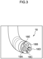
- Fig. 3 is an enlarged view of the distal end 18 of the insertion portion 14 of the endoscope device 12.
- the distal end 18 of the insertion portion 14 is provided with a camera 18A as an example of an imaging device, and light guides 18B and 18C capable of outputting light of a specific wavelength.
- the light outputted from the light guides 18B and 18C is light guided by an optical fiber from a light source device (not illustrated) provided to the control device 19.
- the distal end 18 of the insertion portion 14 is provided with a forceps opening 18D and a nozzle 18E. Instruments for performing various medical procedures enter and exit from the forceps opening 18D. Moreover, water, air, or the like is outputted from the nozzle 18E.
- Light of a specific wavelength is outputted from the light source device of the endoscope device 12 according to the present embodiment, and light of the specific wavelength is outputted from the light guides 18B and 18C, which are examples of the light output unit.
- the light source device is configured to be capable of outputting light having a wavelength of 1000 [nm] to 1500 [nm].
- the light source device (not illustrated) of the control device 19 is configured to be capable of outputting light having a wavelength of 1050 to 1105 [nm] (hereinafter simply referred to as "first light”.), light having a wavelength of 1145 to 1200 [nm] (hereinafter simply referred to as “second light”.), light having a wavelength of 1245 to 1260 [nm] (hereinafter simply referred to as “third light”.), and light having a wavelength of 1350 to 1405 [nm] (hereinafter simply referred to as "fourth light”.).
- first light light having a wavelength of 1050 to 1105 [nm]
- second light light having a wavelength of 1145 to 1200 [nm]
- third light light having a wavelength of 1245 to 1260 [nm]
- fourth light light having a wavelength of 1350 to 1405 [nm]
- Such light components are light components of a specific wavelength selected in advance.
- the endoscope device 12 performs control to irradiate the gastrointestinal tract area in the living body with the first light, and captures an image (hereinafter simply referred to as a "first image”.) using the camera 18A at that time. Furthermore, the endoscope device 12 performs control to irradiate the gastrointestinal tract area in the living body with the second light, and captures an image (hereinafter simply referred to as a "second image”.) using the camera 18A at that time. The endoscope device 12 performs control to irradiate the gastrointestinal tract area in the living body with the third light, and captures an image (hereinafter simply referred to as a "third image".) using the camera 18A at that time. The endoscope device 12 performs control to irradiate the gastrointestinal tract area in the living body with the fourth light, and captures an image (hereinafter simply referred to as a "fourth image".) using the camera 18A at that time.
- first image hereinafter simply referred to as a "
- the control device 19 acquires each image captured by the camera of the endoscope device 12.
- the control device 19 integrates the first image, the second image, the third image, and the fourth image to generate an image Im of the gastrointestinal tract area as illustrated in Fig. 4 .
- the pixel P of the image Im of the gastrointestinal tract area is obtained by arranging the pixel P1 of the first image, the pixel P2 of the second image, the pixel P3 of the third image, and the pixel P4 of the fourth image in the same position in each of the first image, the second image, the third image, and the fourth image.
- the control device 19 then transmits the image Im of the gastrointestinal tract area to the image processing device 30.
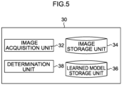
- Fig. 5 is a block diagram representing the functional configuration of the image processing device 30.
- the image processing device 30 includes an image acquisition unit 32, an image storage unit 34, a learned model storage unit 36, and a determination unit 38.
- the image acquisition unit 32 acquires the image Im of the gastrointestinal tract area transmitted from the control device 19.
- the image acquisition unit 32 then temporarily stores the image Im of the gastrointestinal tract area, in the image storage unit 34.
- the image storage unit 34 stores the image Im of the gastrointestinal tract area.
- the learned model storage unit 36 stores a learned model generated in advance for detecting a GIST that is present inside the gastrointestinal tract area from the image Im of the gastrointestinal tract area.
- the learned model according to the present embodiment is realized by, for example, a known neural network.
- the learned model according to the present embodiment is a model generated in advance based on data in which an in-vivo image for training and information (so-called label) indicating whether or not a GIST is present inside a gastrointestinal tract area appearing in the in-vivo image are associated with each other.
- Fig. 6 illustrates an example of a learned model according to the present embodiment.
- the pixel values P1 to P4 of the pixels P of the image Im of the gastrointestinal tract area are inputted to the learned model.
- a probability indicating whether or not a GIST is present at a point corresponding to the pixel P is outputted.
- a probability 0.7 of being a GIST and a probability 0.3 of not being a GIST are outputted from the learned model. Whether or not the GIST is present is determined for each of a plurality of pixels included in the image Im of the gastrointestinal tract area.
- the determination unit 38 inputs the pixel value of each pixel of the image Im of the gastrointestinal tract area stored in the image storage unit 34 to the learned model stored in the learned model storage unit 36, and determines, for each pixel in the image Im of the gastrointestinal tract area, whether or not a GIST is present.
- the determination unit 38 determines that a GIST is present in the point corresponding to the pixel. Furthermore, in a case in which a certain pixel is inputted to the learned model, when the probability of being a GIST is equal to or less than the probability of not being a GIST, the determination unit 38 determines that a GIST is not present at a point corresponding to the pixel.
- the determination unit 38 outputs, to a display unit (not illustrated), the determination result regarding the presence or absence of a GIST for each pixel in the image Im of the gastrointestinal tract area.
- a display unit (not illustrated) displays the determination result, outputted from the determination unit 38, regarding the presence or absence of a GIST. Note that the determination result regarding the presence or absence of a GIST is outputted, for example, in a format superimposed on the image Im of the gastrointestinal tract area (for example, the point where the GIST is present is displayed in red.). The user then checks the determination result displayed on the display unit.
- Fig. 7 is a block diagram illustrating a hardware configuration of a computer 20 which is a component of the control device 19 and the image processing device 30.
- the computer 20 includes a central processing unit (CPU) 21, a read only memory (ROM) 22, a random access memory (RAM) 23, a storage 24, an input unit 25, a display unit 26, and a communication interface (I/F) 27.
- the respective configurations are communicably connected to each other via a bus 29.
- the CPU 21 is a central processing unit, and executes various programs and controls each unit. That is, the CPU 21 reads a program from the ROM 22 or the storage 24, and executes the program using the RAM 23 as a work area. The CPU 21 performs control of each of the foregoing configurations and various types of arithmetic processing according to the program stored in the ROM 22 or the storage 24. In the present embodiment, the ROM 22 or the storage 24 stores various programs for processing information inputted from the input device.
- the ROM 22 stores various programs and various data. Serving as a work area, the RAM 23 temporarily stores programs or data.
- the storage 24 is configured from a hard disk drive (HDD) or a solid state drive (SSD) or the like, and stores various programs including an operating system, and various data.
- the input unit 25 includes a pointing device such as a mouse, and a keyboard, and is used to perform various inputs.
- the display unit 26 is, for example, a liquid crystal display, and displays various types of information.
- the display unit 26 may function as the input unit 25 by adopting a touch panel system.
- the communication I/F 27 is an interface for communicating with another device such as an input device, and for example, standards such as Ethernet (registered trademark), FDDI, and Wi-Fi (registered trademark) are used.
- Ethernet registered trademark
- FDDI FDDI
- Wi-Fi Wi-Fi
- the endoscope device 12 performs control to irradiate the gastrointestinal tract area with the first light, and captures the first image by using the camera 18A at that time. Further, the endoscope device 12 performs control to irradiate the gastrointestinal tract area with the second light, and captures the second image by using the camera 18A at that time. Further, the endoscope device 12 performs control to irradiate the gastrointestinal tract area with the third light, and captures the third image by using the camera 18A at that time. The endoscope device 12 performs control to irradiate the gastrointestinal tract area with the fourth light, and captures the fourth image by using the camera 18A at that time.
- the control device 19 integrates the first image, the second image, the third image, and the fourth image to generate an image Im of the gastrointestinal tract area as illustrated in Fig. 4 .
- the control device 19 then transmits the image Im of the gastrointestinal tract area to the image processing device 30.
- the image acquisition unit 32 of the image processing device 30 stores the image Im of the gastrointestinal tract area, in the image storage unit 34.
- the image processing device 30 upon receiving an instruction signal to start determination processing to determine whether or not a GIST is present at each point of the image Im of the gastrointestinal tract area, the image processing device 30 executes the image processing routine illustrated in Fig. 8 .
- the CPU 21 performs image processing by reading the image processing program from the ROM 22 or the storage 24, expanding the image processing program in the RAM 23, and executing the image processing program.
- step S50 the image acquisition unit 32 reads the image Im of the gastrointestinal tract area stored in the image storage unit 34.
- step S52 the determination unit 38 reads the learned model stored in the learned model storage unit 36.
- step S54 the determination unit 38 inputs the pixel value of each pixel of the image Im of the gastrointestinal tract area read in step S50 to the learned model read in step S52, and determines whether or not there is a GIST for each pixel in the image Im of the gastrointestinal tract area.
- step S56 the determination unit 38 outputs the determination result regarding the presence or absence of a GIST for each pixel in the image Im of the gastrointestinal tract area to the display unit 26, and terminates the image processing routine.
- the display unit 26 displays the determination result regarding the presence or absence of a GIST thus outputted from the determination unit 38.
- the endoscope device outputs light having a wavelength of 1000 [nm] to 1500 [nm], more specifically, first light representing light having a wavelength of 1050 to 1105 [nm], second light representing light having a wavelength of 1145 to 1200 [nm], third light representing light having a wavelength of 1245 to 1260 [nm], and fourth light representing light having a wavelength of 1350 to 1405 [nm], and captures an image when the gastrointestinal tract area in the living body is irradiated with the light.
- the image processing device inputs the image of the gastrointestinal tract area to a learned model generated in advance for detecting a GIST that is present inside the gastrointestinal tract area from the image of the gastrointestinal tract area, and determines whether or not a GIST is present at each point of the image.
- the presence or absence of a GIST can be detected using an image captured by irradiating a gastrointestinal tract area in a living body with light of a specific wavelength.
- the presence or absence of a GIST can be detected without mounting a large-scale imaging device such as a near-infrared hyperspectral camera on an endoscope device.
- light having a specific wavelength is selected from near-infrared light
- light having a wavelength useful for GIST detection is selected using a neural network which is an example of a learned model obtained by machine learning and using partial least square discriminant analysis (PLS-DA) which is an example of a statistical model obtained by statistical analysis.
- PLS-DA partial least square discriminant analysis
- Table 1 shows the number of training data used in generating the neural network and the PLS-DA. As described above, in the present embodiment, because the presence or absence of a GIST is determined for each pixel, the number of pieces of training data corresponds to the number of pixels. Note that “Tumor” in Table 1 represents a pixel in which GIST is present, and “Normal” represents a pixel corresponding to a normal region in which a GIST is not present. Furthermore, the number at the left end of Table 1 represents the date on which the image was collected; for example, "20160923 " represents September 23, 2016.
- Fig. 9 illustrates a configuration of a neural network used for wavelength selection in this Example.
- "Input” represents an input layer
- “Output” represents an output layer.
- “fc” in Fig. 9 represents a fully connected layer, and the number written together represents the number of units.
- “Relu” represents a rectified linear unit (ReLU) which is a known activation function.
- “Dropout” indicates that dropout, which is a known method, is used.
- softmax represents a known softmax function.
- the neural network of Fig. 9 was learned using the training data of Table 1.
- the contribution amount of light of each wavelength was then calculated using the learned weight parameter of the neural network.
- the contribution amount refers to which wavelength of light has a strong influence on correctly identifying the input, and is calculated based on a result of performing forward propagation calculation on an input in which all inputs of wavelengths other than a certain wavelength are set to 0.
- the detailed steps to calculate the contribution amount are as follows.
- Two values which are ultimately outputted by the learned neural network are, for example, ⁇ 0.7, 0.3 ⁇ (indicating a tumor or a normal pixel).
- the larger of the two output values of the learned neural network is selected, and it is specified whether the pixel is a tumor pixel or a normal pixel. For example, in a case in which the output value when the pixel value of a certain pixel is inputted to the learned neural network is ⁇ 0.7, 0.3 ⁇ , the pixel is determined to be a tumor.
- wavelengths that contribute to a correct output there exist, among those wavelengths, wavelengths that contribute to a correct output and wavelengths that contribute to an incorrect output. For example, consider a case in which correct data of a certain pixel is ⁇ 1, 0 ⁇ and the pixel is a tumor. In this case, it is assumed that ⁇ 0.7, 0.3 ⁇ is outputted in a case in which the pixel values corresponding to all the wavelengths of the pixels have been inputted to the learned neural network. A wavelength that directs this output value toward ⁇ 1, 0 ⁇ is a wavelength that contributes to the correct output, and a wavelength that directs this output value toward ⁇ 0, 1 ⁇ is a wavelength that contributes to the incorrect output.
- one piece of data (the pixel value of one pixel) of the training data is inputted to the learned neural network with a value other than a certain wavelength as 0, and a final output value is calculated.
- the output of the node that directs the final output value in the wrong direction is set to 0.
- the sum of the output values calculated as described above for a plurality of pieces of data (the pixel values of a plurality of pixels) is calculated and set as the contribution amount of the wavelength.
- the correct data of a certain pixel is ⁇ 1, 0 ⁇ and a pixel value corresponding to a certain wavelength is inputted to the learned neural network as ⁇ 0.8, 0.2 ⁇ , 0.8 is the calculated value.
- the calculated value thus calculated is also calculated for a plurality of pixels, and the sum of the calculated values calculated for the plurality of pixels is set as the contribution amount. The same calculation is executed for each of the plurality of wavelengths, and the contribution amounts of the wavelengths are calculated.
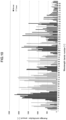
- Fig. 10 illustrates contribution amounts obtained through calculation.
- the vertical axis in Fig. 10 represents the contribution amount (denoted as the "Average contribution amount” in the drawing), and the horizontal axis represents the wavelength (denoted as the "Wavelength bands number” in the drawing).
- each number of the wavelength on the horizontal axis represents each wavelength, the number “1” corresponds to a wavelength of 913.78 [nm], and the number "193" corresponds to a wavelength of 2126.27 [nm].
- the wavelength increases by 6.28 to 6.34 [nm] every time the number increases by 1.
- Tables 2 and 3 below show correspondence relationships between numbers and wavelengths.
- four wavelengths in a region having a high contribution amount were selected from Fig. 10 .
- the accuracy was as illustrated in Fig. 11 .
- light having a wavelength of 1050 to 1105 [nm], light having a wavelength of 1145 to 1200 [nm], light having a wavelength of 1245 to 1260 [nm], and light having a wavelength of 1350 to 1405 [nm] are light having wavelengths useful for detecting a GIST.
- wavelength selection and discrimination are performed using PLS-DA, which is a known statistical method.
- the identification model was generated by PLS-DA by using the training data in Table 1.
- the contribution amount of the light of each wavelength was calculated using the sum of the factor loads of the light of each wavelength up to the eighth principal component of the generated identification model. Therefore, the contribution amount is the sum of the factor loads of the light of each wavelength up to the eighth principal component of the generated identification model.
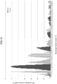
- Fig. 12 illustrates contribution amounts obtained through calculation.
- the vertical axis in Fig. 12 represents the contribution amount (denoted as "The coefficient of linear model” in the drawing).
- the contribution amount denoted as "The coefficient of linear model” in the drawing.
- peaks having a high contribution amount are formed, and it is considered that a GIST can be accurately detected by selecting the wavelength from these peaks.
- Table 4 shows the GIST discrimination accuracy using the neural network (denoted as "proposed technique” in Table 4) and the GIST discrimination accuracy by PLS-DA. Note that the number in parentheses in Table 4 represents the number of wavelengths. "After dimension reduction” indicates that four wavelengths are selected from all wavelengths and that the dimension is reduced. As shown in Table 4, detection accuracy substantially equivalent to that in a case in which all the wavelengths are used is obtained only by using light of four selected wavelengths. [Table 4] Proposed method PLS-DA All wavelengths 97.6% (196) 93.1% (196) After dimension reduction 95.9% (4) 91.4% (4) Accuracy[%] (Number of wavelengths)
- the accuracy in this case is substantially equivalent to the detection accuracy in a case in which the light having the wavelength in all the regions of near-infrared light is used.
- a lung cancer-related Example Light of a specific wavelength useful for detecting lung cancer was selected using the same method as in the above GIST-related Example.
- the wavelength range is 196 wavelengths of 913.78 [nm] to 2145.15 [nm].
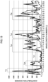
- Fig. 13 illustrates contribution amounts obtained through calculation.
- the vertical axis in Fig. 13 represents the contribution amount (denoted as "contribution degree” in the drawing), and the horizontal axis represents the wavelength number. Note that each number of the wavelength on the horizontal axis represents each wavelength, the number "1" corresponds to a wavelength of 913.78 [nm], and the number "193" corresponds to a wavelength of 2126.27 [nm].
- Fig. 13 The larger the absolute value of the contribution amounts illustrated in Fig. 13 , the more useful the wavelength is for detecting lung cancer.
- the broken lines in Fig. 13 represent contribution amounts when a tumor is discriminated as a tumor, a dot-dash line represents the contribution amount when a normal region is discriminated as a normal region, and a solid line represents the sum of these contribution amounts.
- each wavelength was selected from a peak having a large contribution amount: 977.12 [nm] light was selected from the wavelength range ⁇ H1 , 1103.74 [nm] light was selected from the wavelength range ⁇ H2 , 1198.65 [nm] light was selected from the wavelength range ⁇ H3 , 1350.40 [nm] light was selected from the wavelength range ⁇ H4 , 1584.13 [nm] light was selected from the wavelength range ⁇ H5 , and 1893.21 [nm] light was selected from the wavelength range ⁇ H6 .
- the wavelength range ⁇ H1 is, for example, a wavelength of 955 to 1020 [nm]
- the wavelength range ⁇ H2 is, for example, a wavelength of 1055 to 1135 [nm]
- the wavelength range ⁇ H3 is, for example, a wavelength of 1135 to 1295 [nm]
- the wavelength range ⁇ H4 is, for example, a wavelength of 1295 to 1510 [nm]
- the wavelength range ⁇ H5 is, for example, a wavelength of 1510 to 1645 [nm]
- the wavelength range ⁇ H6 is, for example, a wavelength of 1820 to 2020 [nm].
- Light having a wavelength of 955 to 1020 [nm] is an example of first light
- light having a wavelength of 1055 to 1135 [nm] is an example of second light
- light having a wavelength of 1135 to 1295 [nm] is an example of third light
- light having a wavelength of 1295 to 1510 [nm] is an example of fourth light
- light having a wavelength of 1510 to 1645 [nm] is an example of fifth light
- light having a wavelength of 1820 to 2020 [nm] is an example of sixth light.
- the accuracy is reduced only by about 5%. Accordingly, it may be said that at least one of light having a wavelength of 955 to 1020 [nm], light having a wavelength of 1055 to 1135 [nm], light having a wavelength of 1135 to 1295 [nm], light having a wavelength of 1295 to 1510 [nm], light having a wavelength of 1510 to 1645 [nm], and light having a wavelength of 1820 to 2020 [nm] is light having a wavelength useful for detecting lung cancer.
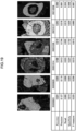
- Figs. 14 and 15 illustrate lung cancer identification results.
- a tumor C is present in an image of a lung specimen (denoted as "NIR image” in the drawing).
- NIR image an image of a lung specimen
- the identification results are hardly different between the result of discriminating the tumor C based on the image obtained by irradiating the lungs with light of all wavelengths (196 wavelengths) (denoted as "196band” in the drawing) and the result of discriminating the tumor C based on the image obtained by irradiating the lungs with light of six wavelengths selected in this Example (denoted as "6band” in the drawing).
- At least one of light having a wavelength of 955 to 1020 [nm], light having a wavelength of 1055 to 1135 [nm], light having a wavelength of 1135 to 1295 [nm], light having a wavelength of 1295 to 1510 [nm], light having a wavelength of 1510 to 1645 [nm], and light having a wavelength of 1820 to 2020 [nm] is light having a wavelength useful for detecting lung cancer.
- a learned SVM model was generated by replacing the neural network according to the GIST-related embodiment above with a support vector machine (SVM), and light of a specific wavelength useful for detection of gastric cancer was selected by a similar method using LASSO (Least Absolute Shrinkage and Selection Operator) for wavelength selection.
- SVM support vector machine
- LASSO Least Absolute Shrinkage and Selection Operator
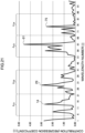
- Fig. 16 illustrates the contribution (regression coefficient) of the model obtained by LASSO.
- the vertical axis represents a LASSO regression coefficient
- the horizontal axis represents a wavelength number. Note that each number of the wavelength on the horizontal axis represents each wavelength, the number “1” corresponds to a wavelength of 1002.45 [nm], and the number “91” corresponds to a wavelength of 1571.5 [nm]. Therefore, in the gastric cancer-related Example, the relationship between the wavelength number and the actual wavelength is not as shown in Tables 2 and 3 above, and the number "1" corresponds to a wavelength of 1002.45 [nm] and the number "91” corresponds to a wavelength of 1571.5 [nm].
- each wavelength is selected from a peak having a large contribution amount: 1091.08 [nm] light (wavelength number 15) is selected from the wavelength range ⁇ S1 , 1217.52 [nm] light (wavelength number 35) is selected from the wavelength range ⁇ S2 , 1287.19 [nm] light (wavelength number 46) is selected from the wavelength range ⁇ S3 , and 1400.96 [nm] light (wavelength number 64) is selected from the wavelength range ⁇ S4 . Note that, when selecting the wavelength, trial and error was performed to select light considered to be useful for identification of gastric cancer.
- the wavelength range ⁇ S1 is, for example, a wavelength of 1065 to 1135 [nm]
- the wavelength range ⁇ S2 is, for example, a wavelength of 1180 to 1230 [nm]
- the wavelength range ⁇ S3 is, for example, a wavelength of 1255 to 1325 [nm]
- the wavelength range ⁇ S4 is, for example, a wavelength of 1350 to 1425 [nm].
- Light having a wavelength of 1065 to 1135 [nm] is an example of first light
- light having a wavelength of 1180 to 1230 [nm] is an example of second light
- light having a wavelength of 1255 to 1325 [nm] is an example of third light
- light having a wavelength of 1350 to 1425 [nm] is an example of fourth light.
- At least one of light having a wavelength of 1065 to 1135 [nm], light having a wavelength of 1180 to 1230 [nm], light having a wavelength of 1255 to 1325 [nm], and light having a wavelength of 1350 to 1425 [nm] is light having a wavelength useful for detecting gastric cancer.
- Figs. 17 to 20 illustrate gastric cancer identification results.
- Fig. 17 are images of a specimen. The numbers in the drawing represent the dates on which the images were taken; for example, "20200923" represents September 23, 2020.
- the region surrounded by a white line in Fig. 17 is a region corresponding to unexposed tumor tissue; the region surrounded by a gray line is a region corresponding to exposed tumor tissue; and the region filled in white is a region corresponding to tumor tissue in a necrotic state.
- Fig. 18 is an image of training data.
- the white region in Fig. 18 is a normal region.
- the gray region in Fig. 18 is a region corresponding to the exposed tumor tissue. Note that, in Fig. 18 , tumor tissue in a necrotic state and unexposed tumor tissue are excluded and not displayed.
- Fig. 19 is a diagram illustrating a region of a tumor estimated from an image obtained by irradiating the stomach with light having a wavelength of 95.
- a dark gray region is a region which is determined to be a tumor
- a light gray area is a region which is determined to be normal.
- the table illustrated in the drawing represents the accuracy, precision, recall, specificity, and F-measure of the determination results for the pixels in each image.
- Fig. 20 is a diagram illustrating a region of a tumor estimated from an image obtained by irradiating the stomach with light of four selected wavelengths.
- a dark gray region is a region which is determined to be a tumor, and a light gray area is a region which is determined to be normal.
- the table illustrated in the drawing represents the accuracy, precision, recall, specificity, and F-measure of the determination results for the pixels in each image.
- At least one of light having a wavelength of 1065 to 1135 [nm], light having a wavelength of 1180 to 1230 [nm], light having a wavelength of 1255 to 1325 [nm], and light having a wavelength of 1350 to 1425 [nm] is light having a wavelength useful for detecting gastric cancer.
- a tumor-bearing mouse-related Example Light of a specific wavelength useful for detecting a tumor was selected using the same method as the method in the above gastric cancer-related Example.
- the tumor-bearing mouse according to this Example is a tumor-bearing mouse in which cells derived from human colorectal cancer are used.
- learning data of 11 specimens normal: 245,866 pix; tumor: 107,078 pix
- leave-one-out cross-validation was used for evaluation of the learned SVM.
- Fig. 21 illustrates the contribution (regression coefficient) of the model obtained by LASSO.
- each number of the wavelengths on the horizontal axis represents each wavelength
- the number "1” corresponds to a wavelength of 1002.45 [nm]
- the number "91” corresponds to a wavelength of 1571.5 [nm]. Therefore, in the tumor-bearing mouse-related Example, the relationship between the wavelength number and the actual wavelength is not as shown in Tables 2 and 3 above, and the number "1” corresponds to a wavelength of 1002.45 [nm] and the number "91” corresponds to a wavelength of 1571.5 [nm].
- each wavelength is selected from a peak having a large contribution amount: 1084.75 [nm] light (wavelength number 14) is selected from the wavelength range ⁇ C1 , 1179.67 [nm] light (wavelength number 29) is selected from the wavelength range ⁇ C2 , 1382.01 [nm] light (wavelength number 61) is selected from the wavelength range ⁇ C3 , and 1470.46 [nm] light (wavelength number 75) is selected from the wavelength range ⁇ C4 . Note that, when selecting the wavelength, trial and error was performed to select light considered to be useful for identification of a tumor.
- the wavelength range ⁇ C1 is, for example, a wavelength of 1020 to 1140 [nm]
- the wavelength range ⁇ C2 is, for example, a wavelength of 1140 to 1260 [nm]
- the wavelength range ⁇ C3 is, for example, a wavelength of 1315 to 1430 [nm]
- the wavelength range ⁇ C4 is, for example, a wavelength of 1430 to 1535 [nm].
- Light having a wavelength of 1020 to 1140 [nm] is an example of first light
- light having a wavelength of 1140 to 1260 [nm] is an example of second light
- light having a wavelength of 1315 to 1430 [nm] is an example of third light
- light having a wavelength of 1430 to 1535 [nm] is an example of fourth light.
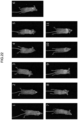
- Figs. 22 to 27 show the results regarding a tumor-bearing mouse.
- Fig. 22 are images of a specimen.
- Fig. 23 is an image of training data.
- the white region in Fig. 23 is a normal region.
- the gray region present in the white region of Fig. 23 is a region corresponding to tumor tissue.
- Figs. 24 and 25 are diagrams illustrating a region of a tumor estimated from an image obtained by irradiating a tumor-bearing mouse with light of 95 wavelengths.
- a white region is a region which is determined to be normal, and a gray region is a region which is determined to be a tumor.
- the table illustrated in the drawing represents the accuracy, precision, recall, specificity, and F-measure of the determination results for the pixels in each image.
- Figs. 26 and 27 are diagrams illustrating a region of a tumor estimated from an image obtained by irradiating a tumor-bearing mouse with light of four selected wavelengths.
- a white region is a region which is determined to be normal, and a gray region is a region which is determined to be a tumor.
- the table illustrated in the drawing represents the accuracy, precision, recall, specificity, and F-measure of the determination results for the pixels in each image.
- At least one of light having a wavelength of 1020 to 1140 [nm], light having a wavelength of 1140 to 1260 [nm], light having a wavelength of 1315 to 1430 [nm], and light having a wavelength of 1430 to 1535 [nm] is light having a wavelength useful for detecting human colorectal cancer.
- each processing which is executed as a result of the CPU reading software (a program), may be executed by various processors other than the CPU.
- the processor in this case include a programmable logic device (PLD) in which a circuit configuration can be changed after manufacturing a field-programmable gate array (FPGA) or the like, a dedicated electric circuit that is a processor having a circuit configuration exclusively designed for executing specific processing such as an application specific integrated circuit (ASIC), and the like.
- PLD programmable logic device
- FPGA field-programmable gate array
- ASIC application specific integrated circuit
- each processing may be executed by one of these various processors, or may be executed by a combination of two or more processors of the same type or different types (for example, a plurality of FPGAs, a combination of a CPU and an FPGA, and so forth).
- the hardware structure of these various processors is, more specifically, an electric circuit in which circuit elements such as semiconductor elements are combined.
- a GIST is detected using a neural network
- the disclosure is not limited thereto.
- a GIST may be detected using the statistical model in the Example.
- a gastrointestinal tract area is irradiated with first light representing light having a wavelength of 1050 to 1105 [nm], second light representing light having a wavelength of 1145 to 1200 [nm], third light representing light having a wavelength of 1245 to 1260 [nm], and fourth light representing light having a wavelength of 1350 to 1405 [nm] to acquire an image
- first light representing light having a wavelength of 1050 to 1105 [nm] second light representing light having a wavelength of 1145 to 1200 [nm]
- third light representing light having a wavelength of 1245 to 1260 [nm] third light representing light having a wavelength of 1245 to 1260 [nm]
- fourth light representing light having a wavelength of 1350 to 1405 [nm] has been described as an example, but the disclosure is not limited thereto.
- a gastrointestinal tract area may be irradiated with at least one of these four light components to acquire an image.
- an image may be acquired by irradiating an area of a living body with at least one
- a GIST may be detected using light of a plurality of wavelengths whose contribution amount in the Examples is equal to or greater than a predetermined threshold value.
- a tumor may be detected using light of a plurality of wavelengths whose contribution amount is equal to or greater than a predetermined threshold value.
- light having a plurality of wavelengths is selected, but any light may be selected as long as the light has a wavelength, from the graph illustrated in the drawing, which can be regarded as useful.
Landscapes
- Health & Medical Sciences (AREA)
- Engineering & Computer Science (AREA)
- Life Sciences & Earth Sciences (AREA)
- Medical Informatics (AREA)
- General Health & Medical Sciences (AREA)
- Surgery (AREA)
- Physics & Mathematics (AREA)
- Public Health (AREA)
- Nuclear Medicine, Radiotherapy & Molecular Imaging (AREA)
- Biomedical Technology (AREA)
- Pathology (AREA)
- Radiology & Medical Imaging (AREA)
- Veterinary Medicine (AREA)
- Molecular Biology (AREA)
- Animal Behavior & Ethology (AREA)
- Biophysics (AREA)
- Heart & Thoracic Surgery (AREA)
- Artificial Intelligence (AREA)
- Optics & Photonics (AREA)
- Computer Vision & Pattern Recognition (AREA)
- Signal Processing (AREA)
- Epidemiology (AREA)
- Primary Health Care (AREA)
- Quality & Reliability (AREA)
- General Physics & Mathematics (AREA)
- Theoretical Computer Science (AREA)
- Evolutionary Computation (AREA)
- Psychiatry (AREA)
- Fuzzy Systems (AREA)
- Mathematical Physics (AREA)
- Physiology (AREA)
- Databases & Information Systems (AREA)
- Spectroscopy & Molecular Physics (AREA)
- Urology & Nephrology (AREA)
- Data Mining & Analysis (AREA)
- Endoscopes (AREA)
- Image Processing (AREA)
- Image Analysis (AREA)
Abstract
Description
- The technology of the present disclosure relates to an image processing device, an image processing method, an image processing program, an endoscope device, and an endoscope image processing system.
- Conventionally, a biological tissue identification device that identifies normality/abnormality of biological tissue is known (for example, see Japanese Patent Application Laid-Open (
JP-A) No. 2009-300131 JP-A No. 2009-300131 - In addition, there is known a biological examination device that evaluates a change in spectral shape between a cancer cell and a normal cell that occurs in a wavelength range of 1510 nm to 1530 nm and/or a wavelength range of 1480 nm to 1500 nm in a spectrum obtained by irradiating biological tissue with near-infrared light, by quantifying the change as a secondary differential value (for example, see Japanese Patent Application (
JP-A) Laid-Open No. 2015-102542 - As disclosed in
JP-A No. 2009-300131 JP-A No. 2015-102542 - The disclosure was conceived in view of the above circumstances, and an object of the disclosure is to detect the presence or absence of a tumor by using an image captured by irradiating an area in a living body with light of a specific wavelength.
- A first aspect of the disclosure is an image processing device, including: an image acquisition unit that acquires an image obtained by irradiating an area in a living body with light having a wavelength of 955 [nm] to 2025 [nm]; and a determination unit that inputs the image acquired by the image acquisition unit to a learned model or a statistical model generated in advance for detecting, from the image, a tumor present in the area, and that determines whether or not a tumor is present at each point in the image acquired by the image acquisition unit.
- A second aspect of the disclosure is an image processing program that causes a computer to function as: an image acquisition unit that acquires an image obtained by irradiating an area in a living body with light having a wavelength of 955 [nm] to 2025 [nm]; and a determination unit that inputs the image acquired by the image acquisition unit to a learned model or a statistical model generated in advance for detecting, from the image, a tumor present in the area, and that determines whether or not a tumor is present at each point in the image acquired by the image acquisition unit.
- A third aspect of the disclosure is an image processing method with which a computer executes processing, including: acquiring an image obtained by irradiating an area in a living body with light having a wavelength of 955 [nm] to 2025 [nm]; and inputting the acquired image to a learned model or a statistical model generated in advance for detecting, from the image, a tumor present in the area, and determining whether or not a tumor is present at each point in the acquired image.
- A fourth aspect of the disclosure is an endoscope device, including: a light output unit that outputs light having a wavelength of 955 [nm] to 2025 [nm]; and an imaging device that captures an image when an area in a living body is irradiated with light from the light output unit.
- A fifth aspect of the disclosure is an image processing device, including: an image acquisition unit that acquires an image obtained by irradiating a gastrointestinal tract area in a living body with light having a wavelength of 1000 [nm] to 1500 [nm]; and a determination unit that inputs the image acquired by the image acquisition unit to a learned model or a statistical model generated in advance for detecting, from the image, a gastrointestinal stromal tumor present in the gastrointestinal tract area, and that determines whether or not a gastrointestinal stromal tumor is present at each point in the image acquired by the image acquisition unit.
- The disclosure affords the advantageous effect that the presence or absence of a tumor can be detected using an image captured by irradiating an area in a living body with light of a specific wavelength.
-
-
Fig. 1 is a diagram illustrating a schematic configuration of an endoscope image processing system according to an embodiment of the disclosure. -
Fig. 2 is a diagram to illustrate a GIST. -
Fig. 3 is an enlarged view of a distal end of an insertion portion of an endoscope device. -
Fig. 4 is a diagram to illustrate an image generated using the present embodiment. -
Fig. 5 is a diagram illustrating an example of a functional configuration of an image processing device according to the present embodiment. -
Fig. 6 is a diagram illustrating an example of a learned model of the present embodiment. -
Fig. 7 is a diagram illustrating a hardware configuration of an image processing device and a control device according to the present embodiment. -
Fig. 8 is an example of an image processing routine according to the present embodiment. -
Fig. 9 is a diagram to illustrate an Example. -
Fig. 10 is a diagram to illustrate an Example. -
Fig. 11 is a diagram to illustrate an Example. -
Fig. 12 is a diagram to illustrate an Example. -
Fig. 13 is a diagram to illustrate an Example. -
Fig. 14 is a diagram to illustrate an Example. -
Fig. 15 is a diagram to illustrate an Example. -
Fig. 16 is a diagram to illustrate an Example. -
Fig. 17 is a diagram to illustrate an Example. -
Fig. 18 is a diagram to illustrate an Example. -
Fig. 19 is a diagram to illustrate an Example. -
Fig. 20 is a diagram to illustrate an Example. -
Fig. 21 is a diagram to illustrate an Example. -
Fig. 22 is a diagram to illustrate an Example. -
Fig. 23 is a diagram to illustrate an Example. -
Fig. 24 is a diagram to illustrate an Example. -
Fig. 25 is a diagram to illustrate an Example. -
Fig. 26 is a diagram to illustrate an Example. -
Fig. 27 is a diagram to illustrate an Example. - An example of an embodiment of the disclosure will be described hereinbelow with reference to the drawings. Note that, in the drawings, the same or equivalent constituent elements and portions are assigned the same reference signs. Furthermore, the dimensional ratios in the drawings are exaggerated for convenience of description, and are sometimes different from the actual ratios.
-
Fig. 1 is a diagram illustrating a schematic configuration of an endoscopeimage processing system 1 according to an embodiment of the disclosure. As illustrated inFig. 1 , the endoscopeimage processing system 1 according to the present embodiment includes anendoscope system 10 and animage processing device 30. Theendoscope system 10 and theimage processing device 30 are connected via apredetermined communication line 5. - The endoscope
image processing system 1 according to the present embodiment detects a gastrointestinal stromal tumor (hereinafter, simply referred to as "GIST".), which is a malignant tumor occurring under the mucosa of the gastrointestinal tract such as the stomach or the small intestine.Fig. 2 is a diagram to illustrate a GIST. As illustrated inFig. 2 , because a GIST occurs under the mucosa of the gastrointestinal tract, it is a tumor which is difficult to detect early. - Conventionally, biological tissue has been irradiated with near-infrared light in all wavelength regions (for example, light having a wavelength around 800 to 2500 nm), and an image of the biological tissue at that time has been captured. In this case, it is necessary to mount, on the endoscope, a camera (for example, a near-infrared hyperspectral camera or the like) capable of capturing images of near-infrared light in all wavelength regions. However, it is difficult to mount such a camera on the endoscope.
- Therefore, according to the present embodiment, light of a specific wavelength useful for discriminating the GIST from the near-infrared light is selected. The endoscope
image processing system 1 according to the present embodiment irradiates a gastrointestinal tract area with light of a specific wavelength selected in advance, and captures an image of the gastrointestinal tract area at that time. Further, the endoscopeimage processing system 1 according to the present embodiment discriminates, based on the captured image, the presence or absence of a GIST at the gastrointestinal tract area. - A specific description will be provided hereinbelow.
- As illustrated in
Fig. 1 , anendoscope system 10 includes anendoscope device 12 and acontrol device 19. Theendoscope device 12 and thecontrol device 19 are electrically connected so as to be able to communicate with each other. Theendoscope device 12 photographs the inside of a human body H. Thecontrol device 19 generates an image of the inside of the living body of the human body H, based on a signal obtained by imaging. - The
endoscope device 12 includes aninsertion portion 14 that is inserted into the human body H. Theinsertion portion 14 is attached to anoperation unit 16. Theoperation unit 16 includes various buttons for instructing an operation such that adistal end 18 of theinsertion portion 14 is curved in the vertical direction and the horizontal direction within a predetermined angle range, collecting a tissue sample by operating a puncture needle attached to thedistal end 18 of theendoscope device 12, and spraying medicine. - The
endoscope device 12 according to the present embodiment is an endoscope for the gastrointestinal tract, and thedistal end 18 is inserted into the gastrointestinal tract of the human body H. A light output unit is provided at thedistal end 18 of theinsertion portion 14 of theendoscope device 12, and light outputted from the light output unit is irradiated onto the gastrointestinal tract area in the living body. Further, theendoscope device 12 acquires an image of the gastrointestinal tract, which is the subject, using an imaging optical system. -
Fig. 3 is an enlarged view of thedistal end 18 of theinsertion portion 14 of theendoscope device 12. As illustrated inFig. 3 , thedistal end 18 of theinsertion portion 14 is provided with acamera 18A as an example of an imaging device, and light guides 18B and 18C capable of outputting light of a specific wavelength. The light outputted from the light guides 18B and 18C is light guided by an optical fiber from a light source device (not illustrated) provided to thecontrol device 19. As illustrated inFig. 3 , thedistal end 18 of theinsertion portion 14 is provided with aforceps opening 18D and anozzle 18E. Instruments for performing various medical procedures enter and exit from theforceps opening 18D. Moreover, water, air, or the like is outputted from thenozzle 18E. - Light of a specific wavelength is outputted from the light source device of the
endoscope device 12 according to the present embodiment, and light of the specific wavelength is outputted from the light guides 18B and 18C, which are examples of the light output unit. Specifically, the light source device is configured to be capable of outputting light having a wavelength of 1000 [nm] to 1500 [nm]. - More specifically, the light source device (not illustrated) of the
control device 19 is configured to be capable of outputting light having a wavelength of 1050 to 1105 [nm] (hereinafter simply referred to as "first light".), light having a wavelength of 1145 to 1200 [nm] (hereinafter simply referred to as "second light".), light having a wavelength of 1245 to 1260 [nm] (hereinafter simply referred to as "third light".), and light having a wavelength of 1350 to 1405 [nm] (hereinafter simply referred to as "fourth light".). Such light components are light components of a specific wavelength selected in advance. - The
endoscope device 12 performs control to irradiate the gastrointestinal tract area in the living body with the first light, and captures an image (hereinafter simply referred to as a "first image".) using thecamera 18A at that time. Furthermore, theendoscope device 12 performs control to irradiate the gastrointestinal tract area in the living body with the second light, and captures an image (hereinafter simply referred to as a "second image".) using thecamera 18A at that time. Theendoscope device 12 performs control to irradiate the gastrointestinal tract area in the living body with the third light, and captures an image (hereinafter simply referred to as a "third image".) using thecamera 18A at that time. Theendoscope device 12 performs control to irradiate the gastrointestinal tract area in the living body with the fourth light, and captures an image (hereinafter simply referred to as a "fourth image".) using thecamera 18A at that time. - The
control device 19 acquires each image captured by the camera of theendoscope device 12. Thecontrol device 19 integrates the first image, the second image, the third image, and the fourth image to generate an image Im of the gastrointestinal tract area as illustrated inFig. 4 . As illustrated inFig. 4 , the pixel P of the image Im of the gastrointestinal tract area is obtained by arranging the pixel P1 of the first image, the pixel P2 of the second image, the pixel P3 of the third image, and the pixel P4 of the fourth image in the same position in each of the first image, the second image, the third image, and the fourth image. - The
control device 19 then transmits the image Im of the gastrointestinal tract area to theimage processing device 30. -
Fig. 5 is a block diagram representing the functional configuration of theimage processing device 30. As illustrated inFig. 5 , theimage processing device 30 includes animage acquisition unit 32, animage storage unit 34, a learnedmodel storage unit 36, and adetermination unit 38. - The
image acquisition unit 32 acquires the image Im of the gastrointestinal tract area transmitted from thecontrol device 19. Theimage acquisition unit 32 then temporarily stores the image Im of the gastrointestinal tract area, in theimage storage unit 34. - The
image storage unit 34 stores the image Im of the gastrointestinal tract area. - The learned
model storage unit 36 stores a learned model generated in advance for detecting a GIST that is present inside the gastrointestinal tract area from the image Im of the gastrointestinal tract area. - The learned model according to the present embodiment is realized by, for example, a known neural network. The learned model according to the present embodiment is a model generated in advance based on data in which an in-vivo image for training and information (so-called label) indicating whether or not a GIST is present inside a gastrointestinal tract area appearing in the in-vivo image are associated with each other.
-
Fig. 6 illustrates an example of a learned model according to the present embodiment. As illustrated inFig. 6 , in the present embodiment, the pixel values P1 to P4 of the pixels P of the image Im of the gastrointestinal tract area are inputted to the learned model. From the learned model, a probability indicating whether or not a GIST is present at a point corresponding to the pixel P is outputted. As illustrated inFig. 6 , for example, a probability 0.7 of being a GIST and a probability 0.3 of not being a GIST are outputted from the learned model. Whether or not the GIST is present is determined for each of a plurality of pixels included in the image Im of the gastrointestinal tract area. - The
determination unit 38 inputs the pixel value of each pixel of the image Im of the gastrointestinal tract area stored in theimage storage unit 34 to the learned model stored in the learnedmodel storage unit 36, and determines, for each pixel in the image Im of the gastrointestinal tract area, whether or not a GIST is present. - For example, in a case in which a certain pixel is inputted to the learned model, when the probability of being a GIST is higher than the probability of not being a GIST, the
determination unit 38 determines that a GIST is present in the point corresponding to the pixel. Furthermore, in a case in which a certain pixel is inputted to the learned model, when the probability of being a GIST is equal to or less than the probability of not being a GIST, thedetermination unit 38 determines that a GIST is not present at a point corresponding to the pixel. - The
determination unit 38 outputs, to a display unit (not illustrated), the determination result regarding the presence or absence of a GIST for each pixel in the image Im of the gastrointestinal tract area. - A display unit (not illustrated) displays the determination result, outputted from the
determination unit 38, regarding the presence or absence of a GIST. Note that the determination result regarding the presence or absence of a GIST is outputted, for example, in a format superimposed on the image Im of the gastrointestinal tract area (for example, the point where the GIST is present is displayed in red.). The user then checks the determination result displayed on the display unit. -
Fig. 7 is a block diagram illustrating a hardware configuration of acomputer 20 which is a component of thecontrol device 19 and theimage processing device 30. As illustrated inFig. 7 , thecomputer 20 includes a central processing unit (CPU) 21, a read only memory (ROM) 22, a random access memory (RAM) 23, astorage 24, aninput unit 25, adisplay unit 26, and a communication interface (I/F) 27. The respective configurations are communicably connected to each other via abus 29. - The
CPU 21 is a central processing unit, and executes various programs and controls each unit. That is, theCPU 21 reads a program from the ROM 22 or thestorage 24, and executes the program using theRAM 23 as a work area. TheCPU 21 performs control of each of the foregoing configurations and various types of arithmetic processing according to the program stored in the ROM 22 or thestorage 24. In the present embodiment, the ROM 22 or thestorage 24 stores various programs for processing information inputted from the input device. - The ROM 22 stores various programs and various data. Serving as a work area, the
RAM 23 temporarily stores programs or data. Thestorage 24 is configured from a hard disk drive (HDD) or a solid state drive (SSD) or the like, and stores various programs including an operating system, and various data. - The
input unit 25 includes a pointing device such as a mouse, and a keyboard, and is used to perform various inputs. - The
display unit 26 is, for example, a liquid crystal display, and displays various types of information. Thedisplay unit 26 may function as theinput unit 25 by adopting a touch panel system. - The communication I/
F 27 is an interface for communicating with another device such as an input device, and for example, standards such as Ethernet (registered trademark), FDDI, and Wi-Fi (registered trademark) are used. - Next, the operation of the endoscope
image processing system 1 will be described. - When the
distal end 18 of theinsertion portion 14 of theendoscope device 12 is inserted into the living body in response to operation by the user and thedistal end 18 reaches the gastrointestinal tract area, imaging of an image of the gastrointestinal tract area is started. - The
endoscope device 12 performs control to irradiate the gastrointestinal tract area with the first light, and captures the first image by using thecamera 18A at that time. Further, theendoscope device 12 performs control to irradiate the gastrointestinal tract area with the second light, and captures the second image by using thecamera 18A at that time. Further, theendoscope device 12 performs control to irradiate the gastrointestinal tract area with the third light, and captures the third image by using thecamera 18A at that time. Theendoscope device 12 performs control to irradiate the gastrointestinal tract area with the fourth light, and captures the fourth image by using thecamera 18A at that time. - The
control device 19 integrates the first image, the second image, the third image, and the fourth image to generate an image Im of the gastrointestinal tract area as illustrated inFig. 4 . Thecontrol device 19 then transmits the image Im of the gastrointestinal tract area to theimage processing device 30. - When acquiring the image Im of the gastrointestinal tract area transmitted from the
control device 19, theimage acquisition unit 32 of theimage processing device 30 stores the image Im of the gastrointestinal tract area, in theimage storage unit 34. - Further, upon receiving an instruction signal to start determination processing to determine whether or not a GIST is present at each point of the image Im of the gastrointestinal tract area, the
image processing device 30 executes the image processing routine illustrated inFig. 8 . - Specifically, the
CPU 21 performs image processing by reading the image processing program from the ROM 22 or thestorage 24, expanding the image processing program in theRAM 23, and executing the image processing program. - In step S50, the
image acquisition unit 32 reads the image Im of the gastrointestinal tract area stored in theimage storage unit 34. - In step S52, the
determination unit 38 reads the learned model stored in the learnedmodel storage unit 36. - In step S54, the
determination unit 38 inputs the pixel value of each pixel of the image Im of the gastrointestinal tract area read in step S50 to the learned model read in step S52, and determines whether or not there is a GIST for each pixel in the image Im of the gastrointestinal tract area. - In step S56, the
determination unit 38 outputs the determination result regarding the presence or absence of a GIST for each pixel in the image Im of the gastrointestinal tract area to thedisplay unit 26, and terminates the image processing routine. - The
display unit 26 displays the determination result regarding the presence or absence of a GIST thus outputted from thedetermination unit 38. - As described above, the endoscope device according to the present embodiment outputs light having a wavelength of 1000 [nm] to 1500 [nm], more specifically, first light representing light having a wavelength of 1050 to 1105 [nm], second light representing light having a wavelength of 1145 to 1200 [nm], third light representing light having a wavelength of 1245 to 1260 [nm], and fourth light representing light having a wavelength of 1350 to 1405 [nm], and captures an image when the gastrointestinal tract area in the living body is irradiated with the light. Further, the image processing device according to the present embodiment inputs the image of the gastrointestinal tract area to a learned model generated in advance for detecting a GIST that is present inside the gastrointestinal tract area from the image of the gastrointestinal tract area, and determines whether or not a GIST is present at each point of the image. Thus, the presence or absence of a GIST can be detected using an image captured by irradiating a gastrointestinal tract area in a living body with light of a specific wavelength. As a result, for example, the presence or absence of a GIST can be detected without mounting a large-scale imaging device such as a near-infrared hyperspectral camera on an endoscope device.
- Next, a method of selecting light of a specific wavelength according to the present embodiment will be described as an Example. In the present embodiment, when light having a specific wavelength is selected from near-infrared light, light having a wavelength useful for GIST detection is selected using a neural network which is an example of a learned model obtained by machine learning and using partial least square discriminant analysis (PLS-DA) which is an example of a statistical model obtained by statistical analysis.
- Table 1 shows the number of training data used in generating the neural network and the PLS-DA. As described above, in the present embodiment, because the presence or absence of a GIST is determined for each pixel, the number of pieces of training data corresponds to the number of pixels. Note that "Tumor" in Table 1 represents a pixel in which GIST is present, and "Normal" represents a pixel corresponding to a normal region in which a GIST is not present. Furthermore, the number at the left end of Table 1 represents the date on which the image was collected; for example, "20160923 " represents September 23, 2016.
[Table 1] Tumor Normal All 20160923 27760 15522 43282 20160930 6090 5382 11472 20171115 18619 1917 20536 20171215 6399 12936 19335 20180202 9617 2332 11949 All 68485 38089 106574 -
Fig. 9 illustrates a configuration of a neural network used for wavelength selection in this Example. InFig. 9 , "Input" represents an input layer, and "Output" represents an output layer. Further, "fc" inFig. 9 represents a fully connected layer, and the number written together represents the number of units. Further, "Relu" represents a rectified linear unit (ReLU) which is a known activation function. In addition, "Dropout " indicates that dropout, which is a known method, is used. Further, "softmax " represents a known softmax function. - In the present embodiment, the neural network of
Fig. 9 was learned using the training data of Table 1. The contribution amount of light of each wavelength was then calculated using the learned weight parameter of the neural network. The contribution amount refers to which wavelength of light has a strong influence on correctly identifying the input, and is calculated based on a result of performing forward propagation calculation on an input in which all inputs of wavelengths other than a certain wavelength are set to 0. The detailed steps to calculate the contribution amount are as follows. - (1) A learned neural network is generated using the training data set. One piece of training data is data in which a pixel value of a certain pixel in an image captured when a gastrointestinal tract area is irradiated with light of each wavelength is associated with a label indicating whether the pixel is a GIST. Note that, when the neural network is learned, the weights of only the fully connected layers in the neural network are learned. Further, the neural network has no bias, and the activation function is the Relu function.
- (2) One piece of data is selected from the training data set, and a pixel value for each wavelength of the data is inputted to the learned neural network to calculate forward propagation. At this time, the output values of all the nodes in the learned neural network are recorded. Note that the output value refers to both a value outputted by each node of the neural network and a value outputted by the output layer of the neural network.
- (3) The pixel value corresponding to one wavelength is selected from the pixel values for each wavelength in the one piece of data used in (2) above, and the pseudo forward propagation is calculated using the learned neural network with the values of the pixel values of the other wavelengths set to 0. The output of the learned neural network at this time is set as a contribution amount of one wavelength of one piece of data. Note that, at this time, the Relu function of the learned neural network is not applied. At this time, for each node of the learned neural network, the output value of the node for which the value recorded in (2) above is 0 or less is calculated as 0.
- (4) (3) above is repeated for all wavelengths of one piece of data, and the contribution amount for the input of the pixel value corresponding to each wavelength is obtained.
- (5) (2) to (4) above are repeated for a plurality of pieces of training data to obtain data of the contribution amounts for the plurality of pieces of training data.
- The contribution amount will be described in specific terms hereinbelow.
- Two values which are ultimately outputted by the learned neural network are, for example, {0.7, 0.3} (indicating a tumor or a normal pixel). The larger of the two output values of the learned neural network is selected, and it is specified whether the pixel is a tumor pixel or a normal pixel. For example, in a case in which the output value when the pixel value of a certain pixel is inputted to the learned neural network is {0.7, 0.3}, the pixel is determined to be a tumor.
- When the pixel values of the pixels corresponding to all the wavelengths have been inputted to the learned neural network, there exist, among those wavelengths, wavelengths that contribute to a correct output and wavelengths that contribute to an incorrect output. For example, consider a case in which correct data of a certain pixel is { 1, 0} and the pixel is a tumor. In this case, it is assumed that {0.7, 0.3} is outputted in a case in which the pixel values corresponding to all the wavelengths of the pixels have been inputted to the learned neural network. A wavelength that directs this output value toward { 1, 0} is a wavelength that contributes to the correct output, and a wavelength that directs this output value toward {0, 1} is a wavelength that contributes to the incorrect output.
- Therefore, one piece of data (the pixel value of one pixel) of the training data is inputted to the learned neural network with a value other than a certain wavelength as 0, and a final output value is calculated. In this case, the output of the node that directs the final output value in the wrong direction is set to 0. This processing corresponds to (2) and (3) above.
- Further, for a certain wavelength, the sum of the output values calculated as described above for a plurality of pieces of data (the pixel values of a plurality of pixels) is calculated and set as the contribution amount of the wavelength. In this case, in a case in which the correct data of a certain pixel is { 1, 0} and a pixel value corresponding to a certain wavelength is inputted to the learned neural network as {0.8, 0.2}, 0.8 is the calculated value. The calculated value thus calculated is also calculated for a plurality of pixels, and the sum of the calculated values calculated for the plurality of pixels is set as the contribution amount. The same calculation is executed for each of the plurality of wavelengths, and the contribution amounts of the wavelengths are calculated.
-
Fig. 10 illustrates contribution amounts obtained through calculation. The vertical axis inFig. 10 represents the contribution amount (denoted as the "Average contribution amount" in the drawing), and the horizontal axis represents the wavelength (denoted as the "Wavelength bands number" in the drawing). Note that each number of the wavelength on the horizontal axis represents each wavelength, the number "1" corresponds to a wavelength of 913.78 [nm], and the number "193" corresponds to a wavelength of 2126.27 [nm]. Note that the wavelength increases by 6.28 to 6.34 [nm] every time the number increases by 1. Tables 2 and 3 below show correspondence relationships between numbers and wavelengths.[Table 2] Wavelength number Wavelength [nm] Wavelength number Wavelength [nm] Wavelength number Wavelength [nm] Wavelength number Wavelength [nm] 1 913.78 33 1116.4 65 1318.8 97 1520.99 2 920.11 34 1122.72 66 1325.12 98 1527.3 3 926.45 35 1129.05 67 1331.44 99 1533.62 4 932.78 36 1135.38 68 1337.76 100 1539.93 5 939.12 37 1141.71 69 1344.08 101 1546.25 6 945.45 38 1148.03 70 1350.4 102 1552.56 7 951.78 39 1154.36 71 1356.72 103 1558.87 8 958.12 40 1160.69 72 1363.05 104 1565.19 9 964.45 41 1167.02 73 1369.37 105 1571.5 10 970.79 42 1173.34 74 1375.69 106 1577.81 11 977.12 43 1179.67 75 1382.01 107 1584.13 12 983.45 44 1186 76 1388.32 108 1590.44 13 989.78 45 1192.32 77 1394.64 109 1596.75 14 996.12 46 1198.65 78 1400.96 110 1603.06 15 1002.45 47 1204.97 79 1407.28 111 1609.38 16 1008.78 48 1211.3 80 1413.6 112 1615.69 17 1015.11 49 1217.62 81 1419.92 113 1622 18 1021.44 50 1223.95 82 1426.24 114 1628.31 19 1027.78 51 1230.27 83 1432.56 115 1634.62 20 1034.11 52 1236.6 84 1438.87 116 1640.94 21 1040.44 53 1242.92 85 1445.19 117 1647.25 22 1046.77 54 1249.25 86 1451.51 118 1653.56 23 1053.1 55 1255.57 87 1457.83 119 1659.87 24 1059.43 56 1261.89 8$ 1464.14 120 1666.18 25 1065.76 57 1268.22 89 1470.46 121 1672.49 26 1072.09 58 1274.54 90 1476.78 122 1678.8 27 1078.42 59 1280.86 91 1483.09 123 1685.11 28 1084.75 60 1287.19 92 1489.41 124 1691.42 29 1091.08 61 1293.51 93 1495.73 125 1697.73 30 1097.41 62 1299.83 94 1502.04 126 1704.04 31 1103.74 63 1306.15 95 1508.36 127 1710.34 32 1110.07 64 1312.48 96 1514.67 128 1716.65 [Table 3] Wavelength number Wavelength [nm] Wavelength number Wavelength [nm] Wavelength number Wavelength [nm] Wavelength number Wavelength [nm] 129 1722.96 161 1924.72 193 2126.27 225 2327.6 130 1729.27 162 1931.02 194 2132.56 226 2333.89 131 1735.58 163 1937.32 195 2138.86 227 2340.18 132 1741.89 164, 1943.63 196 2145.15 228 2346.46 133 1748.19 165 1949.93 197 2151.45 229 2352.75 134 1754.5 166 1956.23 198 2157.74 230 2359.04 135 1760.81 167 1962.53 199 2164.03 231 2365.33 136 1767.11 168 1968.83 200 2170.33 232 2371.61 137 1773.42 169 1975.13 201 2176.62 233 2377.9 138 1779.73 170 1981.43 202 2182.91 234 2384.19 139 1786.03 171 1987.73 203 2189.21 235 2390.47 140 1792.34 172 1994.03 204 2195.5 236 2396.76 141 1798.65 173 2000.33 205 2201.79 237 2403.04 142 1804.95 174 2006.63 206 2208.08 238 2409.33 143 1811.26 175 201.2.92 207 2214.38 239 2415.62 144 1817.56 176 2019.22 208 2220.67 240 2421.9 145 1823.87 177 2025.52 209 2226.96 241 2428.19 146 1830.17 178 2031.82 210 2233.25 242 2434.47 147 1836.48 179 2038.12 211 2239.54 243 2440.75 148 1842.78 180 2044.42 212 2245.83 244 2447.04 149 1849.09 181 2050.71 213 2252.13 245 2453.32 130 1855.39 182 2057.01 214 2258.42 246 2459.61 151 1861.69 183 2063.31 215 2264.71 247 2465.89 152 1868 184 2069.6 216 2271 248 2472.17 153 1874.3 185 2075.9 217 2277.29 249 2478.46 154 1880.61 186 2082.2 218 2283.58 250 2484.74 155 1886.91 187 2088.49 219 2289.87 251 2491.02 156 1893.21 188 2094.79 220 2296.16 252 2497.31 157 1899.51 189 2101.09 221 2302.45 253 2503.59 158 1905.82 190 2107.38 222 2308.73 254 2509.87 159 1912.12 191 2113.68 223 2315.02 255 2516.15 160 1918.42 192 2119.97 224 2321.31 256 2522.44 - The larger the absolute value of the contribution amounts illustrated in
Fig. 10 , the more useful the wavelength is for detecting a GIST. In the Example, four wavelengths in a region having a high contribution amount were selected fromFig. 10 . Specifically, based on the premise that each wavelength is selected from the peaks having a high contribution amount, the accuracy was as illustrated inFig. 11 . - Accordingly, it may be said that light having a wavelength of 1050 to 1105 [nm], light having a wavelength of 1145 to 1200 [nm], light having a wavelength of 1245 to 1260 [nm], and light having a wavelength of 1350 to 1405 [nm] are light having wavelengths useful for detecting a GIST.
- In the present embodiment, wavelength selection and discrimination are performed using PLS-DA, which is a known statistical method. Specifically, the identification model was generated by PLS-DA by using the training data in Table 1. The contribution amount of the light of each wavelength was calculated using the sum of the factor loads of the light of each wavelength up to the eighth principal component of the generated identification model. Therefore, the contribution amount is the sum of the factor loads of the light of each wavelength up to the eighth principal component of the generated identification model.
-
Fig. 12 illustrates contribution amounts obtained through calculation. The vertical axis inFig. 12 represents the contribution amount (denoted as "The coefficient of linear model" in the drawing). Similarly to the wavelength selection using the neural network, peaks having a high contribution amount are formed, and it is considered that a GIST can be accurately detected by selecting the wavelength from these peaks. - Table 4 below shows the GIST discrimination accuracy using the neural network (denoted as "proposed technique" in Table 4) and the GIST discrimination accuracy by PLS-DA. Note that the number in parentheses in Table 4 represents the number of wavelengths. "After dimension reduction" indicates that four wavelengths are selected from all wavelengths and that the dimension is reduced. As shown in Table 4, detection accuracy substantially equivalent to that in a case in which all the wavelengths are used is obtained only by using light of four selected wavelengths.
[Table 4] Proposed method PLS-DA All wavelengths 97.6% (196) 93.1% (196) After dimension reduction 95.9% (4) 91.4% (4) Accuracy[%] (Number of wavelengths) - As described above, in a case in which, according to the present embodiment, a GIST is detected using light having a selected wavelength, it can be said that the accuracy in this case is substantially equivalent to the detection accuracy in a case in which the light having the wavelength in all the regions of near-infrared light is used.
- Next, a lung cancer-related Example will be described. Light of a specific wavelength useful for detecting lung cancer was selected using the same method as in the above GIST-related Example. The wavelength range is 196 wavelengths of 913.78 [nm] to 2145.15 [nm].
Fig. 13 illustrates contribution amounts obtained through calculation. The vertical axis inFig. 13 represents the contribution amount (denoted as "contribution degree" in the drawing), and the horizontal axis represents the wavelength number. Note that each number of the wavelength on the horizontal axis represents each wavelength, the number "1" corresponds to a wavelength of 913.78 [nm], and the number "193" corresponds to a wavelength of 2126.27 [nm]. - The larger the absolute value of the contribution amounts illustrated in
Fig. 13 , the more useful the wavelength is for detecting lung cancer. The broken lines inFig. 13 represent contribution amounts when a tumor is discriminated as a tumor, a dot-dash line represents the contribution amount when a normal region is discriminated as a normal region, and a solid line represents the sum of these contribution amounts. - In this Example, six wavelengths in a region having a high contribution amount were selected from
Fig. 13 . Specifically, each wavelength was selected from a peak having a large contribution amount: 977.12 [nm] light was selected from the wavelength range λH1, 1103.74 [nm] light was selected from the wavelength range λH2, 1198.65 [nm] light was selected from the wavelength range λH3, 1350.40 [nm] light was selected from the wavelength range λH4, 1584.13 [nm] light was selected from the wavelength range λH5, and 1893.21 [nm] light was selected from the wavelength range λH6. Although the contribution amount corresponding to the wavelength range λH3 inFig. 13 is smaller than the contribution amounts of other wavelength ranges, light of 1198.65 [nm] in the wavelength range λH3 was selected because light of the wavelength range λH3 was considered to be useful for identification of lung cancer through trial and error in wavelength selection. Note that the wavelength range λH1 is, for example, a wavelength of 955 to 1020 [nm], the wavelength range λH2 is, for example, a wavelength of 1055 to 1135 [nm], the wavelength range λH3 is, for example, a wavelength of 1135 to 1295 [nm], the wavelength range λH4 is, for example, a wavelength of 1295 to 1510 [nm], the wavelength range λH5 is, for example, a wavelength of 1510 to 1645 [nm], and the wavelength range λH6 is, for example, a wavelength of 1820 to 2020 [nm]. Light having a wavelength of 955 to 1020 [nm] is an example of first light, light having a wavelength of 1055 to 1135 [nm] is an example of second light, light having a wavelength of 1135 to 1295 [nm] is an example of third light, light having a wavelength of 1295 to 1510 [nm] is an example of fourth light, light having a wavelength of 1510 to 1645 [nm] is an example of fifth light, and light having a wavelength of 1820 to 2020 [nm] is an example of sixth light. When the presence or absence of a tumor present in lungs in a living body was detected using an image captured by irradiating the lungs with light of these specific wavelengths, the accuracy was as shown in the following table.[Table 5] Validation Accuracy All wavelengths (196 wavelengths) 94.3% After dimension reduction (6 wavelengths) 89.3% (6) - As shown in the above table, it can be seen that even if the total wavelength (196 wavelengths) is reduced to 6 wavelengths, the accuracy is reduced only by about 5%. Accordingly, it may be said that at least one of light having a wavelength of 955 to 1020 [nm], light having a wavelength of 1055 to 1135 [nm], light having a wavelength of 1135 to 1295 [nm], light having a wavelength of 1295 to 1510 [nm], light having a wavelength of 1510 to 1645 [nm], and light having a wavelength of 1820 to 2020 [nm] is light having a wavelength useful for detecting lung cancer.
- Furthermore,
Figs. 14 and15 illustrate lung cancer identification results. In the identification results shown inFigs. 14 and15 , a tumor C is present in an image of a lung specimen (denoted as "NIR image" in the drawing). In contrast, it can be seen that the identification results are hardly different between the result of discriminating the tumor C based on the image obtained by irradiating the lungs with light of all wavelengths (196 wavelengths) (denoted as "196band" in the drawing) and the result of discriminating the tumor C based on the image obtained by irradiating the lungs with light of six wavelengths selected in this Example (denoted as "6band" in the drawing). Accordingly, it may also be said that at least one of light having a wavelength of 955 to 1020 [nm], light having a wavelength of 1055 to 1135 [nm], light having a wavelength of 1135 to 1295 [nm], light having a wavelength of 1295 to 1510 [nm], light having a wavelength of 1510 to 1645 [nm], and light having a wavelength of 1820 to 2020 [nm] is light having a wavelength useful for detecting lung cancer. - Next, a gastric cancer-related Example will be described. A learned SVM model was generated by replacing the neural network according to the GIST-related embodiment above with a support vector machine (SVM), and light of a specific wavelength useful for detection of gastric cancer was selected by a similar method using LASSO (Least Absolute Shrinkage and Selection Operator) for wavelength selection. When the learned SVM model was generated, learning data of 6 specimens (normal: 405,525 pix, tumor: 107,078 pix) was used. In addition, leave-one-out cross-validation was used for evaluation of the learned SVM.
Fig. 16 illustrates the contribution (regression coefficient) of the model obtained by LASSO. InFig. 16 , the vertical axis represents a LASSO regression coefficient, and the horizontal axis represents a wavelength number. Note that each number of the wavelength on the horizontal axis represents each wavelength, the number "1" corresponds to a wavelength of 1002.45 [nm], and the number "91" corresponds to a wavelength of 1571.5 [nm]. Therefore, in the gastric cancer-related Example, the relationship between the wavelength number and the actual wavelength is not as shown in Tables 2 and 3 above, and the number "1" corresponds to a wavelength of 1002.45 [nm] and the number "91" corresponds to a wavelength of 1571.5 [nm]. - In this Example, four wavelengths in a region having a high contribution were selected from
Fig. 16 . Specifically, each wavelength is selected from a peak having a large contribution amount: 1091.08 [nm] light (wavelength number 15) is selected from the wavelength range λS1, 1217.52 [nm] light (wavelength number 35) is selected from the wavelength range λS2, 1287.19 [nm] light (wavelength number 46) is selected from the wavelength range λS3, and 1400.96 [nm] light (wavelength number 64) is selected from the wavelength range λS4. Note that, when selecting the wavelength, trial and error was performed to select light considered to be useful for identification of gastric cancer. Note that the wavelength range λS1 is, for example, a wavelength of 1065 to 1135 [nm], the wavelength range λS2 is, for example, a wavelength of 1180 to 1230 [nm], the wavelength range λS3 is, for example, a wavelength of 1255 to 1325 [nm], and the wavelength range λS4 is, for example, a wavelength of 1350 to 1425 [nm]. Light having a wavelength of 1065 to 1135 [nm] is an example of first light, light having a wavelength of 1180 to 1230 [nm] is an example of second light, light having a wavelength of 1255 to 1325 [nm] is an example of third light, and light having a wavelength of 1350 to 1425 [nm] is an example of fourth light. When the presence or absence of a tumor present in a stomach in a living body was detected using an image captured by irradiating the stomach with light of these specific wavelengths, the accuracy was as shown in the following table. Note that all the wavelengths (95) correspond to wavelengths from the number "1" wavelength 1002.45 [nm] to the number "95" wavelength 1596.75 [nm].[Table 6] All wavelengths (95) Selected wavelengths (4) Accuracy 0.784 0.800 Precision 0.920 0.773 Recall 0.746 0.968 Specificity 0.500 0.512 F-measure 0.971 0.859 - As shown in the above table, it can be seen that there is no significant difference in accuracy, precision, recall, specificity, and F-measure between all (95) wavelengths and the selected (4) wavelengths. Accordingly, it may be said that at least one of light having a wavelength of 1065 to 1135 [nm], light having a wavelength of 1180 to 1230 [nm], light having a wavelength of 1255 to 1325 [nm], and light having a wavelength of 1350 to 1425 [nm] is light having a wavelength useful for detecting gastric cancer.
- Furthermore,
Figs. 17 to 20 illustrate gastric cancer identification results.Fig. 17 are images of a specimen. The numbers in the drawing represent the dates on which the images were taken; for example, "20200923" represents September 23, 2020. The region surrounded by a white line inFig. 17 is a region corresponding to unexposed tumor tissue; the region surrounded by a gray line is a region corresponding to exposed tumor tissue; and the region filled in white is a region corresponding to tumor tissue in a necrotic state. -
Fig. 18 is an image of training data. The white region inFig. 18 is a normal region. The gray region inFig. 18 is a region corresponding to the exposed tumor tissue. Note that, inFig. 18 , tumor tissue in a necrotic state and unexposed tumor tissue are excluded and not displayed. -
Fig. 19 is a diagram illustrating a region of a tumor estimated from an image obtained by irradiating the stomach with light having a wavelength of 95. A dark gray region is a region which is determined to be a tumor, and a light gray area is a region which is determined to be normal. In addition, the table illustrated in the drawing represents the accuracy, precision, recall, specificity, and F-measure of the determination results for the pixels in each image. -
Fig. 20 is a diagram illustrating a region of a tumor estimated from an image obtained by irradiating the stomach with light of four selected wavelengths. A dark gray region is a region which is determined to be a tumor, and a light gray area is a region which is determined to be normal. The table illustrated in the drawing represents the accuracy, precision, recall, specificity, and F-measure of the determination results for the pixels in each image. - When
Fig. 19 andFig. 20 are compared, it can be seen that there is not so much difference in the determination result. Accordingly, it may also be said that at least one of light having a wavelength of 1065 to 1135 [nm], light having a wavelength of 1180 to 1230 [nm], light having a wavelength of 1255 to 1325 [nm], and light having a wavelength of 1350 to 1425 [nm] is light having a wavelength useful for detecting gastric cancer. - Next, a tumor-bearing mouse-related Example will be described. Light of a specific wavelength useful for detecting a tumor was selected using the same method as the method in the above gastric cancer-related Example. Note that the tumor-bearing mouse according to this Example is a tumor-bearing mouse in which cells derived from human colorectal cancer are used. In this Example, learning data of 11 specimens (normal: 245,866 pix; tumor: 107,078 pix) was used. In addition, leave-one-out cross-validation was used for evaluation of the learned SVM.
Fig. 21 illustrates the contribution (regression coefficient) of the model obtained by LASSO. Note that, as per the gastric cancer-related Example, each number of the wavelengths on the horizontal axis represents each wavelength, the number "1" corresponds to a wavelength of 1002.45 [nm], and the number "91" corresponds to a wavelength of 1571.5 [nm]. Therefore, in the tumor-bearing mouse-related Example, the relationship between the wavelength number and the actual wavelength is not as shown in Tables 2 and 3 above, and the number "1" corresponds to a wavelength of 1002.45 [nm] and the number "91" corresponds to a wavelength of 1571.5 [nm]. - In this Example, four wavelengths in a region having a high contribution were selected from
Fig. 21 . Specifically, each wavelength is selected from a peak having a large contribution amount: 1084.75 [nm] light (wavelength number 14) is selected from the wavelength range λC1, 1179.67 [nm] light (wavelength number 29) is selected from the wavelength range λC2, 1382.01 [nm] light (wavelength number 61) is selected from the wavelength range λC3, and 1470.46 [nm] light (wavelength number 75) is selected from the wavelength range λC4. Note that, when selecting the wavelength, trial and error was performed to select light considered to be useful for identification of a tumor. Note that the wavelength range λC1 is, for example, a wavelength of 1020 to 1140 [nm], the wavelength range λC2 is, for example, a wavelength of 1140 to 1260 [nm], the wavelength range λC3 is, for example, a wavelength of 1315 to 1430 [nm], and the wavelength range λC4 is, for example, a wavelength of 1430 to 1535 [nm]. Light having a wavelength of 1020 to 1140 [nm] is an example of first light, light having a wavelength of 1140 to 1260 [nm] is an example of second light, light having a wavelength of 1315 to 1430 [nm] is an example of third light, and light having a wavelength of 1430 to 1535 [nm] is an example of fourth light. Note that, when selecting the wavelength, trial and error was performed to select light considered to be useful for identification of a mouse-borne tumor. When the presence or absence of a tumor was detected using an image captured by irradiating a tumor-bearing mouse with light of these specific wavelengths, the accuracy was as shown in the following table.[Table 7] All wavelengths (95) Selected wavelengths (4) Accuracy 0.885 0.891 Precision 0.276 0.287 Recall 0.917 0.909 Specificity 0.883 0.890 F-measure 0.424 0.436 - As shown in the above table, it can be seen that there is no significant difference in accuracy, precision, recall, specificity, and F-measure between all (95) wavelengths and the selected (4) wavelengths.
- In addition,
Figs. 22 to 27 show the results regarding a tumor-bearing mouse.Fig. 22 are images of a specimen.Fig. 23 is an image of training data. The white region inFig. 23 is a normal region. The gray region present in the white region ofFig. 23 is a region corresponding to tumor tissue. -
Figs. 24 and25 are diagrams illustrating a region of a tumor estimated from an image obtained by irradiating a tumor-bearing mouse with light of 95 wavelengths. A white region is a region which is determined to be normal, and a gray region is a region which is determined to be a tumor. In addition, the table illustrated in the drawing represents the accuracy, precision, recall, specificity, and F-measure of the determination results for the pixels in each image. -
Figs. 26 and27 are diagrams illustrating a region of a tumor estimated from an image obtained by irradiating a tumor-bearing mouse with light of four selected wavelengths. A white region is a region which is determined to be normal, and a gray region is a region which is determined to be a tumor. The table illustrated in the drawing represents the accuracy, precision, recall, specificity, and F-measure of the determination results for the pixels in each image. - When
Fig. 24 andFig. 25 , andFig. 26 andFig. 27 are compared, it can be seen that there is not so much difference in the determination result. Accordingly, it may also be said that at least one of light having a wavelength of 1020 to 1140 [nm], light having a wavelength of 1140 to 1260 [nm], light having a wavelength of 1315 to 1430 [nm], and light having a wavelength of 1430 to 1535 [nm] is light having a wavelength useful for detecting human colorectal cancer. - Each of the above-described Examples is applicable to the foregoing embodiment, and can have a similar system configuration.
- Note that, in the foregoing embodiments, each processing, which is executed as a result of the CPU reading software (a program), may be executed by various processors other than the CPU. Examples of the processor in this case include a programmable logic device (PLD) in which a circuit configuration can be changed after manufacturing a field-programmable gate array (FPGA) or the like, a dedicated electric circuit that is a processor having a circuit configuration exclusively designed for executing specific processing such as an application specific integrated circuit (ASIC), and the like. Moreover, each processing may be executed by one of these various processors, or may be executed by a combination of two or more processors of the same type or different types (for example, a plurality of FPGAs, a combination of a CPU and an FPGA, and so forth). Furthermore, the hardware structure of these various processors is, more specifically, an electric circuit in which circuit elements such as semiconductor elements are combined.
- Note that the disclosure is not limited to or by the foregoing embodiment, rather, a variety of variations and applications are possible within a scope not departing from the spirit of the invention.
- For example, in the embodiment, a case in which a GIST is detected using a neural network has been described as an example, but the disclosure is not limited thereto. For example, a GIST may be detected using the statistical model in the Example.
- Further, in the embodiment, a case in which a gastrointestinal tract area is irradiated with first light representing light having a wavelength of 1050 to 1105 [nm], second light representing light having a wavelength of 1145 to 1200 [nm], third light representing light having a wavelength of 1245 to 1260 [nm], and fourth light representing light having a wavelength of 1350 to 1405 [nm] to acquire an image has been described as an example, but the disclosure is not limited thereto. A gastrointestinal tract area may be irradiated with at least one of these four light components to acquire an image. In addition, the same applies to each of the Examples, and an image may be acquired by irradiating an area of a living body with at least one of the light components.
- Further, in the foregoing embodiment, a case in which a GIST is detected using light of four wavelengths has been described as an example, but the disclosure is not limited thereto. For example, a GIST may be detected using light of a plurality of wavelengths whose contribution amount in the Examples is equal to or greater than a predetermined threshold value. Furthermore, the same applies to the Examples, and a tumor may be detected using light of a plurality of wavelengths whose contribution amount is equal to or greater than a predetermined threshold value.
- Moreover, in each of the Examples, light having a plurality of wavelengths is selected, but any light may be selected as long as the light has a wavelength, from the graph illustrated in the drawing, which can be regarded as useful.
- The disclosure of
Japanese Patent Application No. 2020-130535, filed on July 31, 2020
Claims (26)
- An image processing device, comprising:an image acquisition unit that acquires an image obtained by irradiating an area of a living body with light having a wavelength of 955 [nm] to 2025 [nm]; anda determination unit that inputs the image acquired by the image acquisition unit to a learned model or a statistical model generated in advance for detecting, from the image, a tumor present in the area, and that determines whether or not a tumor is present at each point in the image acquired by the image acquisition unit.
- The image processing device according to claim 1,wherein the image acquisition unit acquires an image obtained by irradiating a gastrointestinal tract area in a living body with light having a wavelength of 1000 [nm] to 1500 [nm], andwherein the determination unit inputs the image acquired by the image acquisition unit to a learned model or a statistical model generated in advance for detecting, from the image, a gastrointestinal stromal tumor present in the gastrointestinal tract area, and determines whether or not a gastrointestinal stromal tumor is present at each point in the image acquired by the image acquisition unit.
- The image processing device according to claim 2,wherein the light is light including at least one offirst light representing light of a wavelength of 1050 to 1105 [nm],second light representing light of a wavelength of 1145 to 1200 [nm],third light representing light of a wavelength of 1245 to 1260 [nm], andfourth light representing light of a wavelength of 1350 to 1405 [nm].
- The image processing device according to claim 3,wherein the light is light includingfirst light representing light of a wavelength of 1050 to 1105 [nm],second light representing light of a wavelength of 1145 to 1200 [nm],third light representing light of a wavelength of 1245 to 1260 [nm], andfourth light representing light of a wavelength of 1350 to 1405 [nm].
- The image processing device according to any one of claims 2 to 4,
wherein the learned model or the statistical model is a model generated in advance based on data in which an in-vivo image for training and information indicating whether or not a gastrointestinal stromal tumor is present inside a gastrointestinal tract area appearing in the in-vivo image are associated with each other. - The image processing device according to any one of claims 2 to 5,
wherein the determination unit inputs a pixel value of each pixel of the image acquired by the image acquisition unit to the learned model or the statistical model, and determines whether or not a gastrointestinal stromal tumor is present for each pixel of the image acquired by the image acquisition unit. - The image processing device according to claim 1,wherein the image acquisition unit acquires an image obtained by irradiating lungs in a living body with light having a wavelength of 955 [nm] to 2025 [nm], andwherein the determination unit inputs the image acquired by the image acquisition unit to a learned model or a statistical model generated in advance for detecting, from the image, a tumor present in the lungs, and determines whether or not a tumor is present at each point in the image acquired by the image acquisition unit.
- The image processing device according to claim 7,wherein the light is light including at least one offirst light representing light of a wavelength of 955 to 1020 [nm],second light representing light of a wavelength of 1055 to 1135 [nm],third light representing light of a wavelength of 1135 to 1295 [nm],fourth light representing light of a wavelength of 1295 to 1510 [nm],fifth light representing light of a wavelength of 1510 to 1645 [nm], andsixth light representing light of a wavelength of 1820 to 2020 [nm].
- The image processing device according to claim 8,wherein the light is light includingfirst light representing light of a wavelength of 955 to 1020 [nm],second light representing light of a wavelength of 1055 to 1135 [nm],third light representing light of a wavelength of 1135 to 1295 [nm],fourth light representing light of a wavelength of 1295 to 1510 [nm],fifth light representing light of a wavelength of 1510 to 1645 [nm], andsixth light representing light of a wavelength of 1820 to 2020 [nm].
- The image processing device according to any one of claims 7 to 9,
wherein the learned model or the statistical model is a model generated in advance based on data in which an in-vivo image for training and information indicating whether or not a tumor is present in the lungs appearing in the in-vivo image are associated with each other. - The image processing device according to claim 1,wherein the image acquisition unit acquires an image obtained by irradiating the stomach in a living body with light having a wavelength of 1085 [nm] to 1405 [nm], andwherein the determination unit inputs the image acquired by the image acquisition unit to a learned model or a statistical model generated in advance for detecting, from the image, a tumor present in the stomach, and determines whether or not a tumor is present at each point in the image acquired by the image acquisition unit.
- The image processing device according to claim 11,wherein the light is light including at least one offirst light representing light of a wavelength of 1065 to 1135 [nm],second light representing light of a wavelength of 1180 to 1230 [nm],third light representing light of a wavelength of 1255 to 1325 [nm], andfourth light representing light of a wavelength of 1350 to 1425 [nm].
- The image processing device according to claim 12,wherein the light is light includingfirst light representing light of a wavelength of 1065 to 1135 [nm],second light representing light of a wavelength of 1180 to 1230 [nm],third light representing light of a wavelength of 1255 to 1325 [nm], andfourth light representing light of a wavelength of 1350 to 1425 [nm].
- The image processing device according to any one of claims 11 to 13,
wherein the learned model or the statistical model is a model generated in advance based on data in which an in-vivo image for training and information indicating whether or not a tumor is present in the stomach appearing in the in-vivo image are associated with each other. - The image processing device according to claim 1,wherein the image acquisition unit acquires an image obtained by irradiating the large bowel in a living body with light having a wavelength of 1020 [nm] to 1540 [nm], andwherein the determination unit inputs the image acquired by the image acquisition unit to a learned model or a statistical model generated in advance for detecting, from the image, a tumor present in the large bowel, and determines whether or not a tumor is present at each point in the image acquired by the image acquisition unit.
- The image processing device according to claim 15,wherein the light is light including at least one offirst light representing light of a wavelength of 1020 to 1140 [nm],second light representing light of a wavelength of 1140 to 1260 [nm],third light representing light of a wavelength of 1315 to 1430 [nm], andfourth light representing light of a wavelength of 1430 to 1535 [nm].
- The image processing device according to claim 15,wherein the light is light includingfirst light representing light of a wavelength of 1020 to 1140 [nm],second light representing light of a wavelength of 1140 to 1260 [nm],third light representing light of a wavelength of 1315 to 1430 [nm], andfourth light representing light of a wavelength of 1430 to 1535 [nm].
- The image processing device according to any one of claims 15 to 17,
wherein the learned model or the statistical model is a model generated in advance based on data in which an in-vivo image for training and information indicating whether or not a tumor is present in the large bowel appearing in the in-vivo image are associated with each other. - An image processing program that causes a computer to function as:an image acquisition unit that acquires an image obtained by irradiating an area of a living body with light having a wavelength of 955 [nm] to 2025 [nm]; anda determination unit that inputs the image acquired by the image acquisition unit to a learned model or a statistical model generated in advance for detecting, from the image, a tumor present in the area, and that determines whether or not a tumor is present at each point in the image acquired by the image acquisition unit.
- An image processing method with which a computer executes processing, comprising:acquiring an image obtained by irradiating an area of a living body with light having a wavelength of 955 [nm] to 2025 [nm]; andinputting the acquired image to a learned model or a statistical model generated in advance for detecting, from the image, a tumor present in the area, and determining whether or not a tumor is present at each point in the acquired image.
- An endoscope device, comprising:a light output unit that outputs light having a wavelength of 955 [nm] to 2025 [nm]; andan imaging device that captures an image when an area of a living body is irradiated with light from the light output unit.
- The endoscope device according to claim 21,wherein the area in the living body is the gastrointestinal tract area, andwherein the light is light including at least one offirst light representing light of a wavelength of 1050 to 1105 [nm],second light representing light of a wavelength of 1145 to 1200 [nm],third light representing light of a wavelength of 1245 to 1260 [nm], andfourth light representing light of a wavelength of 1350 to 1405 [nm].
- The endoscope device according to claim 21,wherein the area in the living body is the lungs, andwherein the light is light including at least one offirst light representing light of a wavelength of 955 to 1020 [nm],second light representing light of a wavelength of 1055 to 1135 [nm],third light representing light of a wavelength of 1135 to 1295 [nm],fourth light representing light of a wavelength of 1295 to 1510 [nm],fifth light representing light of a wavelength of 1510 to 1645 [nm], andsixth light representing light of a wavelength of 1820 to 2020 [nm].
- The endoscope device according to claim 21,wherein the area in the living body is the stomach, andwherein the light is light including at least one offirst light representing light of a wavelength of 1065 to 1135 [nm],second light representing light of a wavelength of 1180 to 1230 [nm],third light representing light of a wavelength of 1255 to 1325 [nm], andfourth light representing light of a wavelength of 1350 to 1425 [nm].
- The endoscope device according to claim 21,wherein the area in the living body is the large bowel, andwherein the light is light including at least one offirst light representing light of a wavelength of 1020 to 1140 [nm],second light representing light of a wavelength of 1140 to 1260 [nm],third light representing light of a wavelength of 1315 to 1430 [nm], andfourth light representing light of a wavelength of 1430 to 1535 [nm].
- An endoscope image processing system, comprising:the endoscope device according to claim 21; andthe image processing device according to claim 1.
Applications Claiming Priority (2)
| Application Number | Priority Date | Filing Date | Title |
|---|---|---|---|
| JP2020130535 | 2020-07-31 | ||
| PCT/JP2021/028496 WO2022025290A1 (en) | 2020-07-31 | 2021-07-30 | Image processing device, image processing method, image processing program, endoscope device, and endoscope image processing system |
Publications (2)
| Publication Number | Publication Date |
|---|---|
| EP4186409A1 true EP4186409A1 (en) | 2023-05-31 |
| EP4186409A4 EP4186409A4 (en) | 2024-01-10 |
Family
ID=80036471
Family Applications (1)
| Application Number | Title | Priority Date | Filing Date |
|---|---|---|---|
| EP21850153.4A Pending EP4186409A4 (en) | 2020-07-31 | 2021-07-30 | IMAGE PROCESSING DEVICE, IMAGE PROCESSING METHOD, IMAGE PROCESSING PROGRAM, ENDOSCOPE DEVICE AND ENDOSCOPE IMAGE PROCESSING SYSTEM |
Country Status (4)
| Country | Link |
|---|---|
| US (1) | US20230218175A1 (en) |
| EP (1) | EP4186409A4 (en) |
| JP (1) | JP7833146B2 (en) |
| WO (1) | WO2022025290A1 (en) |
Family Cites Families (17)
| Publication number | Priority date | Publication date | Assignee | Title |
|---|---|---|---|---|
| JP4575474B2 (en) * | 2008-06-11 | 2010-11-04 | 国立大学法人東京工業大学 | Biological tissue identification apparatus and method |
| JP5246798B2 (en) * | 2009-10-16 | 2013-07-24 | 住友電気工業株式会社 | Biological tissue identification apparatus and method |
| JP5341707B2 (en) * | 2009-10-16 | 2013-11-13 | 住友電気工業株式会社 | Biological tissue identification apparatus and method |
| JP6446357B2 (en) * | 2013-05-30 | 2018-12-26 | 株式会社ニコン | Imaging system |
| JP2015102542A (en) | 2013-11-28 | 2015-06-04 | 住友電気工業株式会社 | Biological inspection device |
| CN107169535B (en) * | 2017-07-06 | 2023-11-03 | 谈宜勇 | Deep learning classification method and device for biological multispectral images |
| US11633084B2 (en) * | 2017-10-30 | 2023-04-25 | Japanese Foundation For Cancer Research | Image diagnosis assistance apparatus, data collection method, image diagnosis assistance method, and image diagnosis assistance program |
| EP3811845A4 (en) * | 2018-06-22 | 2022-03-16 | AI Medical Service Inc. | METHOD OF ASSISTING A DISEASE DIAGNOSIS BASED ON AN ENDOSCOPE IMAGE OF THE DIGESTIVE ORGAN, DIAGNOSIS SUPPORT SYSTEM, DIAGNOSIS SUPPORT PROGRAM AND COMPUTER READABLE RECORDING MEDIUM WITH THE DIAGNOSIS SUPPORT PROGRAM STORED THEREON |
| DE112019004880T5 (en) * | 2018-09-27 | 2021-07-01 | Hoya Corporation | ELECTRONIC ENDOSCOPIC SYSTEM |
| WO2020075578A1 (en) * | 2018-10-12 | 2020-04-16 | 富士フイルム株式会社 | Medical image processing device, endoscope system, and medical image processing method |
| EP3884838A4 (en) * | 2018-11-21 | 2022-08-17 | AI Medical Service Inc. | Disease diagnostic assistance method based on digestive organ endoscopic images, diagnostic assistance system, diagnostic assistance program, and computer-readable recording medium having diagnostic assistance program stored thereon |
| WO2020116115A1 (en) * | 2018-12-04 | 2020-06-11 | Hoya株式会社 | Information processing device and model generation method |
| US11172184B2 (en) * | 2018-12-13 | 2021-11-09 | Covidien Lp | Systems and methods for imaging a patient |
| JP2020130535A (en) | 2019-02-18 | 2020-08-31 | 国立大学法人九州大学 | Voice transmission status evaluation system and voice transmission status evaluation method |
| US11793399B2 (en) * | 2019-06-20 | 2023-10-24 | Cilag Gmbh International | Super resolution and color motion artifact correction in a pulsed hyperspectral imaging system |
| US12453592B2 (en) * | 2019-12-30 | 2025-10-28 | Cilag Gmbh International | Adaptive surgical system control according to surgical smoke cloud characteristics |
| KR102277761B1 (en) * | 2020-04-09 | 2021-07-14 | 금오공과대학교 산학협력단 | Method for processing endoscopy image using deep learning |
-
2021
- 2021-07-30 EP EP21850153.4A patent/EP4186409A4/en active Pending
- 2021-07-30 US US18/007,367 patent/US20230218175A1/en active Pending
- 2021-07-30 JP JP2022539630A patent/JP7833146B2/en active Active
- 2021-07-30 WO PCT/JP2021/028496 patent/WO2022025290A1/en not_active Ceased
Also Published As
| Publication number | Publication date |
|---|---|
| EP4186409A4 (en) | 2024-01-10 |
| WO2022025290A1 (en) | 2022-02-03 |
| US20230218175A1 (en) | 2023-07-13 |
| JPWO2022025290A1 (en) | 2022-02-03 |
| JP7833146B2 (en) | 2026-03-19 |
Similar Documents
| Publication | Publication Date | Title |
|---|---|---|
| Marsden et al. | Intraoperative margin assessment in oral and oropharyngeal cancer using label-free fluorescence lifetime imaging and machine learning | |
| JP6890184B2 (en) | Medical image processing equipment and medical image processing program | |
| AU2015284810B2 (en) | Raman spectroscopy system, apparatus, and method for analyzing, characterizing, and/or diagnosing a type or nature of a sample or a tissue such as an abnormal growth | |
| EP2870462B1 (en) | Methods utilizing fiber-optic raman spectroscopy | |
| US12053145B2 (en) | Medical image processing apparatus and method | |
| US20120166211A1 (en) | Method and apparatus for aiding imaging diagnosis using medical image, and image diagnosis aiding system for performing the method | |
| EP3529591B1 (en) | Method and system for detecting an anomaly within a biological tissue | |
| US20160007858A1 (en) | Imaging system with hyperspectral camera guided probe | |
| WO2021055837A9 (en) | Artificial intelligence coregistration and marker detection, including machine learning and using results thereof | |
| JP2021101900A (en) | Learning data creation device, method and program and medical image recognition device | |
| KR20200038121A (en) | Endoscopic device and method for diagnosing gastric lesion based on gastric endoscopic image obtained in real time | |
| US12112472B2 (en) | Artifact removal from multimodality OCT images | |
| Römer et al. | Enhancing oral health diagnostics with hyperspectral imaging and computer vision: clinical dataset study | |
| Zhang et al. | Medical biometrics: computerized TCM data analysis | |
| US20230218175A1 (en) | Image Processing Device, Image Processing Method, Image Processing Program, Endoscope Device, and Endoscope Image Processing System | |
| CN119770001A (en) | Application method and system of Raman spectroscopy system based on ICCD and fiber-optic gating | |
| EP4370017B1 (en) | Systems utilizing raman spectroscopy for in vivo analysis | |
| CN117649413A (en) | A deep learning-assisted diagnosis method for intestinal cancer based on traditional Chinese medicine tongue image | |
| van der Stel et al. | Real-time peri-operative microcalcification detection in superficial breast tissues | |
| Kodogiannis et al. | Neural network-based approach for the classification of wireless-capsule endoscopic images | |
| Nadimi et al. | Towards full integration of artificial intelligence in colon capsule endoscopy's pathway | |
| Lu et al. | Diagnosis of Colonic Tissue by Spectral Analysis Technology Combined with Artificial Intelligence | |
| KR102517232B1 (en) | Method for removing reflected light of medical image based on machine learning and device using the same | |
| Finkšt et al. | Autofluorescence bronchoscopy image processing in the selected colour spaces | |
| Charoenlap et al. | Diagnostic Accuracy and Reproducibility of ChatGPT-4o for HER2 Immunohistochemistry Scoring in Equivocal Breast Cancer Cases |
Legal Events
| Date | Code | Title | Description |
|---|---|---|---|
| STAA | Information on the status of an ep patent application or granted ep patent |
Free format text: STATUS: THE INTERNATIONAL PUBLICATION HAS BEEN MADE |
|
| PUAI | Public reference made under article 153(3) epc to a published international application that has entered the european phase |
Free format text: ORIGINAL CODE: 0009012 |
|
| STAA | Information on the status of an ep patent application or granted ep patent |
Free format text: STATUS: REQUEST FOR EXAMINATION WAS MADE |
|
| 17P | Request for examination filed |
Effective date: 20230223 |
|
| AK | Designated contracting states |
Kind code of ref document: A1 Designated state(s): AL AT BE BG CH CY CZ DE DK EE ES FI FR GB GR HR HU IE IS IT LI LT LU LV MC MK MT NL NO PL PT RO RS SE SI SK SM TR |
|
| DAV | Request for validation of the european patent (deleted) | ||
| DAX | Request for extension of the european patent (deleted) | ||
| REG | Reference to a national code |
Ref country code: DE Ref legal event code: R079 Free format text: PREVIOUS MAIN CLASS: A61B0001045000 Ipc: A61B0001000000 |
|
| A4 | Supplementary search report drawn up and despatched |
Effective date: 20231213 |
|
| RIC1 | Information provided on ipc code assigned before grant |
Ipc: G06T 7/00 20170101ALI20231207BHEP Ipc: A61B 1/06 20060101ALI20231207BHEP Ipc: A61B 1/04 20060101ALI20231207BHEP Ipc: A61B 1/00 20060101AFI20231207BHEP |