EP4186216B1 - Centralized management of data flow maps for distributed edge node deployment - Google Patents
Centralized management of data flow maps for distributed edge node deployment Download PDFInfo
- Publication number
- EP4186216B1 EP4186216B1 EP20768783.1A EP20768783A EP4186216B1 EP 4186216 B1 EP4186216 B1 EP 4186216B1 EP 20768783 A EP20768783 A EP 20768783A EP 4186216 B1 EP4186216 B1 EP 4186216B1
- Authority
- EP
- European Patent Office
- Prior art keywords
- iot
- data
- applications
- device applications
- sensors
- Prior art date
- Legal status (The legal status is an assumption and is not a legal conclusion. Google has not performed a legal analysis and makes no representation as to the accuracy of the status listed.)
- Active
Links
Images




Classifications
-
- H—ELECTRICITY
- H04—ELECTRIC COMMUNICATION TECHNIQUE
- H04L—TRANSMISSION OF DIGITAL INFORMATION, e.g. TELEGRAPHIC COMMUNICATION
- H04L69/00—Network arrangements, protocols or services independent of the application payload and not provided for in the other groups of this subclass
- H04L69/24—Negotiation of communication capabilities
-
- G—PHYSICS
- G16—INFORMATION AND COMMUNICATION TECHNOLOGY [ICT] SPECIALLY ADAPTED FOR SPECIFIC APPLICATION FIELDS
- G16Y—INFORMATION AND COMMUNICATION TECHNOLOGY SPECIALLY ADAPTED FOR THE INTERNET OF THINGS [IoT]
- G16Y40/00—IoT characterised by the purpose of the information processing
- G16Y40/30—Control
- G16Y40/35—Management of things, i.e. controlling in accordance with a policy or in order to achieve specified objectives
-
- H—ELECTRICITY
- H04—ELECTRIC COMMUNICATION TECHNIQUE
- H04L—TRANSMISSION OF DIGITAL INFORMATION, e.g. TELEGRAPHIC COMMUNICATION
- H04L41/00—Arrangements for maintenance, administration or management of data switching networks, e.g. of packet switching networks
- H04L41/14—Network analysis or design
- H04L41/145—Network analysis or design involving simulating, designing, planning or modelling of a network
-
- H—ELECTRICITY
- H04—ELECTRIC COMMUNICATION TECHNIQUE
- H04L—TRANSMISSION OF DIGITAL INFORMATION, e.g. TELEGRAPHIC COMMUNICATION
- H04L67/00—Network arrangements or protocols for supporting network services or applications
- H04L67/01—Protocols
- H04L67/12—Protocols specially adapted for proprietary or special-purpose networking environments, e.g. medical networks, sensor networks, networks in vehicles or remote metering networks
Definitions
- This application is generally related to Internet of Things (IOT) technology and, more specifically, to centralized management of data flow maps for distributed edge node deployment.
- IOT Internet of Things
- IOT Internet of Things
- Many industries have implemented Internet of Things (IOT) technology, which can connect machinery, sensors, control systems, or the like, in an industrial environment, to computers for remote monitoring and control.
- Many of the machines, sensors, and control systems in the industrial environment can have external interfaces to output information corresponding to their operations to a server via an edge node acting as a protocol translator for transmissions between the industrial environment and the server.
- edge node acting as a protocol translator for transmissions between the industrial environment and the server.
- specially-programmed edge node can receive the information output from the machines, sensors, and control systems in the industrial environment in one transmission protocol, filter or aggregate the data received from the machines, sensors, and control systems in an attempt to reduce the volume of data uploaded to the server for subsequent processing, and transmit the information to the server with a different transmission protocol.
- Each data flow from the external interfaces of the machines, sensors, and control systems in the industrial environment to the server through one or more edge nodes typically include custom configurations.
- the machines, sensors, and control systems in the industrial environment can include custom logic to output data at an external interface using a particular protocol
- the edge nodes can be specially-programmed or hard-coded in static flows, for example, performing data compression, data transformation, such as fast Fourier Transform operations, feature extraction, data combination from various sources, such as data convolution.
- These customized data flows are hardcoded in the industrial environment to enable the transmission of data from the machines, sensors, and control systems to the server. Hardcoding the data flows into the edge nodes, machines, sensors, and control system is time consuming and renders the overall industrial environment inflexible and difficult to scale.
- Document US 2020/084113 A1 discloses a method for a contextual transformation of an analytical model for an industrial internet of things (IIoT) edge node.
- the analytical model is received from a cloud service, local data of the IIoT edge node is obtained, and the local data is analyzed to determine a situational context of the IIoT edge node.
- IIoT internet of things
- Document US 2018/338017 A1 discloses a method to compress, aggregate and archive Internet of Things data originating from sensors can use a point cloud based geometric data model and a distribution and aggregation method based on compressed point cloud representations.
- Document US 2020/112490 A1 discloses a framework for dynamic management of analytic functions such as data processors and machine learned ("ML") models for an Internet of Things intelligent edge that addresses management of the lifecycle of the analytic functions from creation to execution, in production.
- the end user will be seamlessly able to check in an analytic function, version it, deploy it, evaluate model performance and deploy refined versions into the data flows at the edge or core dynamically for existing and new end points.
- the framework comprises a hypergraph-based model as a foundation, and may use a microservices architecture with the ML infrastructure and models deployed as containerized microservices.
- This application discloses a method, a computer program product and an apparatus, such as a computing system, to generate models of managed devices and applications in an Internet of Things (IOT) system by identifying each endpoint in the managed devices and applications capable of transmitting or receiving the data and defining flows for data from the endpoints in sensors to endpoints of IOT servers via endpoints of the programmable edge device applications.
- the computing system can develop a data flow map to define a connectivity of the programmable edge device applications to the sensors and the servers in the IOT system for exchanging the data from the sensors to the servers in the IOT system via the programmable edge device applications.
- the computing system can prompt configuration of the managed devices and applications in the IOT system based on the data flow map, which implements the connectivity of the programmable edge device applications to the sensors and to servers in the IOT system. Embodiments will be described in greater detail below.
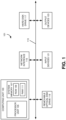
- FIG. 1 shows an illustrative example of a computing device 101.
- the computing device 101 includes a computing unit 103 with a processing unit 105 and a system memory 107.
- the processing unit 105 may be any type of programmable electronic device for executing software instructions, but will conventionally be a microprocessor.
- the system memory 107 may include both a read-only memory (ROM) 109 and a random access memory (RAM) 111.
- ROM read-only memory
- RAM random access memory
- both the read-only memory (ROM) 109 and the random access memory (RAM) 111 may store software instructions for execution by the processing unit 105.
- the processing unit 105 and the system memory 107 are connected, either directly or indirectly, through a bus 113 or alternate communication structure, to one or more peripheral devices 117-123.
- the processing unit 105 or the system memory 107 may be directly or indirectly connected to one or more additional memory storage devices, such as a hard disk drive 117, which can be magnetic and/or removable, a removable optical disk drive 119, and/or a flash memory card.
- the processing unit 105 and the system memory 107 also may be directly or indirectly connected to one or more input devices 121 and one or more output devices 123.
- the input devices 121 may include, for example, a keyboard, a pointing device (such as a mouse, touchpad, stylus, trackball, or joystick), a scanner, a camera, and a microphone.
- the output devices 123 may include, for example, a monitor display, a printer and speakers.
- one or more of the peripheral devices 117-123 may be internally housed with the computing unit 103. Alternately, one or more of the peripheral devices 117-123 may be external to the housing for the computing unit 103 and connected to the bus 113 through, for example, a Universal Serial Bus (USB) connection.
- USB Universal Serial Bus
- the computing unit 103 may be directly or indirectly connected to a network interface 115 for communicating with other devices making up a network.
- the network interface 115 can translate data and control signals from the computing unit 103 into network messages according to one or more communication protocols, such as the transmission control protocol (TCP) and the Internet protocol (IP).
- TCP transmission control protocol
- IP Internet protocol
- the network interface 115 may employ any suitable connection agent (or combination of agents) for connecting to a network, including, for example, a wireless transceiver, a modem, or an Ethernet connection.
- connection agent or combination of agents
- computing device 101 is illustrated as an example only, and it not intended to be limiting.
- Various embodiments may be implemented using one or more computing devices that include the components of the computing device 101 illustrated in Figure 1 , which include only a subset of the components illustrated in Figure 1 , or which include an alternate combination of components, including components that are not shown in Figure 1 .
- various embodiments may be implemented using a multi-processor computer, a plurality of single and/or multiprocessor computers arranged into a network, or some combination of both.
- the processor unit 105 can have more than one processor core.
- Figure 2 illustrates an example of a multi-core processor unit 105 that may be employed with various embodiments.
- the processor unit 105 includes a plurality of processor cores 201A and 201B.
- Each processor core 201A and 201B includes a computing engine 203A and 203B, respectively, and a memory cache 205A and 205B, respectively.
- a computing engine 203A and 203B can include logic devices for performing various computing functions, such as fetching software instructions and then performing the actions specified in the fetched instructions.
- Each computing engine 203A and 203B may then use its corresponding memory cache 205A and 205B, respectively, to quickly store and retrieve data and/or instructions for execution.
- Each processor core 201A and 201B is connected to an interconnect 207.
- the particular construction of the interconnect 207 may vary depending upon the architecture of the processor unit 105. With some processor cores 201A and 201B, such as the Cell microprocessor created by Sony Corporation, Toshiba Corporation and IBM Corporation, the interconnect 207 may be implemented as an interconnect bus. With other processor units 201A and 201B, however, such as the Opteron TM and Athlon TM dual-core processors available from Advanced Micro Devices of Sunnyvale, California, the interconnect 207 may be implemented as a system request interface device. In any case, the processor cores 201A and 201B communicate through the interconnect 207 with an input/output interface 209 and a memory controller 210.
- the input/output interface 209 provides a communication interface to the bus 113.
- the memory controller 210 controls the exchange of information to the system memory 107.
- the processor unit 105 may include additional components, such as a high-level cache memory accessible shared by the processor cores 201A and 201B. It also should be appreciated that the description of the computer network illustrated in Figure 1 and Figure 2 is provided as an example only, and it not intended to suggest any limitation as to the scope of use or functionality of alternate embodiments.
- IOT Internet of Things
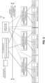
- Figure 3 illustrates an example of an Internet of Things (IOT) system 300 implemented in a server environment 301 and an on-premises environment 302 according to various embodiments.
- the on-premises environment 302 of the IOT system 300 can include multiple sensor systems 330-1 to 300-N, each including one or more sensors or other devices capable of communicating with one or more IOT edge nodes 500-1 to 500-N.
- the sensor system 330-1 can communicate with the IOT edge node 500-1
- the sensor system 330-2 can communicate with the IOT edge node 500-2
- the sensor system 330-N can communicate with the IOT edge node 500-N.
- one or more of the sensor systems 330-1 to 330-N can communicate with any of the IOT edge nodes 500-1 to 500-N and, as will be described below in greater detail, be configured (and dynamically reconfigured) by a data flow server 340 to communicate with various embedded applications hosted in the IOT edge nodes 500-1 to 500-N.
- the sensors in the sensor systems 330-1 to 330-N can gather information corresponding to the manufacturing of a product, for example, by identifying operations or operational states of manufacturing equipment, manufacturing lines, the manufacturing of products, inventory, testing or verification procedures for the products, or the like.
- the sensors in the sensor systems 330-1 to 330-N can transmit the gathered information towards an IOT server 310 via one or more of the IOT edge nodes 500-1 to 500-N.
- the TOT edge nodes 500-1 to 500-N can include embedded application systems 510-1 to 510-N, respectively, to process the information received from the sensor systems 330-1 to 330-N.
- the embedded application systems 510-1 to 510-N can determine states of the machinery, manufacturing lines, equipment, products, inventory, or the like, based on the information received from the sensor system 330-1 to 330-N.
- the embedded application systems 510-1 to 510-N can generate messages based on the determined states and transmit the messages to the IOT server 310.
- the embedded application systems 510-1 to 510-N, in the IOT edge nodes 500-1 to 500-N, respectively, can be generic or programmable with regard to the data flow from the sensor system 330-1 to 330-N to the IOT server 310.
- the data flow server 340 can deploy a configuration, for example, from a data flow map, to the IOT edge nodes 500-1 to 500-N, which can configure the embedded application system 510-1 to 510-N to implement a data flow from the sensor system 330-1 to 330-N to the IOT server 310.
- the data flow server 340 also can update the configuration of the IOT edge nodes 500-1 to 500-N to implement different data flows from the sensor system 330-1 to 330-N to the IOT server 310, for example, based on a different data flow map. Embodiments will be described below in greater detail.
- the IOT edge nodes 500-1 to 500-N can include a processing systems configured to execute instructions corresponding to embedded applications, which can prompt the processing systems to analyze the information received from the sensor systems 330-1 to 330-N, generate the messages, and transmit the messages to the IOT server 310.
- the IOT edge nodes 500-1 to 500-N can receive the embedded applications as container images from the IOT server 310 located in the server environment 301.
- the embedded application systems 510-1 to 510-N can implement Docker engines to execute the container images.
- the container images can be standalone, executable embedded applications, which can include executable code, runtime, system tools, system libraries, settings, or the like, utilized by the Docker engines to implement the embedded applications corresponding to the container images.
- the IOT server 310 can include an application manager 400 to deploy containers having container images to the IOT edge nodes 500-1 to 500-N.
- the application manager 400 can select an embedded application to implement in one of the IOT edge nodes 500-1 to 500-N, for example, from an application repository 320 located in the server environment 301, and generate a container to deploy the selected embedded application to the corresponding IOT edge nodes 500-1 to 500-N.
- the addition of embedded application systems 510-1 to 510-N to the IOT edge nodes 500-1 to 500-N, respectively, can allow for deployment of the containers and corresponding container images by the application manager 400 to the IOT edge nodes 500-1 to 500-N, which can allow the IOT server 310 to centrally control a flow of information gathered by the sensor systems 330-1 to 330-N to the IOT server 310.
- the application manager 400 in the IOT server 310 also can orchestrate various operations performed by the embedded application systems 510-1 to 510-N in the IOT edge nodes 500-1 to 500-N, respectively.
- the application manager 400 can utilize the embedded application systems 510-1 to 510-N to off-load processing from the server environment 301 to the IOT edge nodes 500-1 to 500-N in the on-premises environment 302.
- the application manager 400 in the IOT server 310 can identify processing and/or memory resources in the IOT edge nodes 500-1 to 500-N that remain after implementing container images for the communication of information gathered by the sensor systems 330-1 to 330-N.
- the application manager 400 can utilize the remaining processing and/or memory resources in the IOT edge nodes 500-1 to 500-N to off-load processing from the server environment 301 to the on-premises environment 302. For example, the application manager 40 can select an embedded application from the application repository 320 corresponding to the operations to be off-loaded to the IOT edge nodes 500-1 to 500-N and deploy a container that includes the embedded application to the corresponding IOT edge nodes 500-1 to 500-N.
- the application manager 400 also can orchestrate the import or export of parameters in the embedded application implemented by the embedded application systems 510-1 to 510-N.
- the parameters in the embedded application can correspond to values coded in the embedded application or values determined by the embedded application during execution. For example, when the embedded application corresponds to a temperature monitoring application that utilizes a temperature reading from a sensor to determine a rate of temperature change over a preset time period and then generates a message when the rate of temperature change exceeds a threshold value, the parameters can correspond to the rate of temperature change and the threshold value.
- the application manager 400 can send a parameter message to one of the IOT edge nodes 500-1 to 500-N implementing the temperature monitoring application, which can include a parameter for the corresponding embedded application systems 510-1 to 510-N to import into the temperature monitoring application, such as a parameter corresponding to a different threshold value.
- the application manager 400 also can send a parameter message to one of the IOT edge nodes 500-1 to 500-N implementing the temperature monitoring application, which can prompt the corresponding embedded application systems 510-1 to 510-N to export a parameter from the temperature monitoring application, such as a parameter corresponding to a threshold value or the rate of temperature change.
- the application manager 400 also can orchestrate the import or export of parameters in the embedded application by implementing an avatar of the embedded application running on the embedded application systems 510-1 to 510-N and then transmitting parameter messaging to the embedded application systems 510-1 to 510-N.
- the parameter messaging can prompt the embedded application systems 510-1 to 510-N to import a parameter from the IOT server 310, which can allow the application manager 40 to modify the embedded application implemented by one or more of embedded application systems 510-1 to 510-N without having to deploy a different embedded application to the IOT edge nodes 500-1 to 500-N.
- the parameter messaging also can prompt the embedded application systems 510-1 to 510-N to import or export parameters to other devices, such as other IOT edge nodes 500-1 to 500-N.
- the application manager 400 can orchestrate the sharing of parameters across the distributed IOT edge nodes 500-1 to 500-N with the parameter messaging, which can allow the IOT edge nodes 500-1 to 500-N to operate in conjunction with each other. Embodiments of the application manager and the embedded application system will be described below in greater detail.
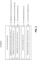
- Figure 4 illustrates an example of an application manager 400 in an IOT server according to various embodiments.
- the IOT server including the application manager 400 can be located in a server environment and be configured to communicate with devices located in an on-premises environment or in a different server environment.
- the application manager 400 can include an embedded application deployment unit 410 to select embedded applications for deployment on IOT edge nodes in an on-premises environment.
- the application manager 400 can select the embedded applications based on input received from a remote user terminal or based on an internal programming.
- the application manager 400 can retrieve a container image corresponding to the selected embedded application from a memory device, such as an application repository located in the server environment or another memory system storing container images accessible by the IOT server.
- the embedded application deployment unit 410 can include a containerized IOT application unit 412 to generate a container 401 that includes the container image corresponding to the selected embedded application.
- the containerized IOT application unit 412 can transmit the container 401 towards the IOT edge node over a communication network, such as packet-switched network, a circuit-switched network, a combination thereof, or the like.
- the IOT edge node can extract the container image from the received container 401 and execute the container image, for example, with a Docker engine or the like, to implement the embedded application on the IOT edge node.
- the implementation of the embedded application can prompt the IOT edge node to generate application messages 402, which the IOT edge node can transmit to the IOT server over the communication network.
- the application messages 402 can include information the IOT edge nodes generated, aggregated, filtered, or the like, in response to the execution of the embedded application corresponding to the container image.
- the application messaging 402 can include a subset of the industrial measurement data, an aggregated report of the industrial measurement data, an indication that the IOT edge node detected an event from industrial measurement data, or the like.
- the embedded application deployment unit 410 can include an embedded application state unit 414 to model states of the embedded applications deployed on IOT edge nodes based, at least in part, on the application messages 402 received from the IOT edge nodes.
- the embedded application state unit 414 can model the states of the embedded application by storing instances of container images capable of being deployed by the application manager 400, instances of container images having been deployed, identifiers of IOT edge nodes having been commissioned to receive container images from the application manager 400, parameters supported by the container images, values of the parameters supported by the container images, or the like.
- the embedded application state unit 414 can update the model of the embedded applications on the IOT edge nodes when a new container image has been deployed to or released from an IOT edge node, based on contents of the application messages 402 from the IOT edge nodes implementing the embedded applications, or the like.
- the model of the embedded application can correspond to an avatar of the deployed container images on the IOT edge nodes, which can mimic the operational states of the deployed container images as implemented on the IOT edge nodes.
- the embedded application state unit 414 can generate a model of the sound classification embedded application that identifies the IOT edge node, identifies the sound classification embedded application has been deployed on the IOT edge node, identifies the parameters associated with the sound classification embedded application, identifies the values of the parameters, or the like.
- the application manager 400 can include a publish-subscribe unit 420 to generate parameter messaging 403, which can prompt the IOT edge nodes to import or export parameters associated with embedded applications implemented by the IOT edge nodes. Since the embedded application state unit 414 can include a model of the embedded application deployed in the IOT edge node, the publish-subscribe unit 420 can generate parameter messaging 403 to import or export parameters associated with the embedded application. In some embodiments, the publish-subscribe unit 420 can include parameter values in the parameter messaging 403 and the IOT edge nodes can import the parameter values into the embedded applications. The ability to import of parameter values into the embedded applications can allow the IOT server to remotely modify a deployed container image without having to release the already deployed container image and deploy a new container 401 with a modified container image.
- the publish-subscribe unit 420 can generate parameter messaging 403 that, when provided to the IOT edge node, can prompt the IOT edge node to export a parameter value as application parameters 404.
- the IOT edge node can transmit the application parameters 404 to the application manager 400 in the IOT server, which can utilize the parameter values to update the model of the embedded application.
- the publish-subscribe unit 420 can retransmit the application parameters 404 to a different networking device or server platform, for example, to a networking device subscribed to receive the parameter value(s) exported from the IOT edge node in the application parameters 404.
- the parameter messaging 403 can specify where the IOT edge node should export the application parameters 404, for example, identify a networking device to receive the application parameters 404.
- the publish-subscribe unit 420 may utilize the models of the embedded applications to identify and track which parameter values to export from which embedded applications and which networking devices, such as other IOT edge nodes subscribe to receive the parameter values.
- the publish-subscribe unit 420 can generate the parameter messaging 403 to prompt an import of parameters from the embedded applications implemented on the IOT edge nodes, to prompt an export of parameters from the embedded applications implemented on the IOT edge nodes, to prompt the embedded applications implemented on the IOT edge nodes share parameters between themselves, or the like.
- the application manager 400 can include a distributed resource utilization unit 430 to utilize multiple distributed IOT edge nodes to implement complex services, for example, by coordinating the deployment of containers 401 to the IOT edge nodes, while utilize the models of the deployed embedded applications along with the publish-subscribe technology to have the embedded applications communicate with each other across the distributed IOT edge nodes.
- the application manager 400 can direct the distributed IOT edge nodes to implement complex computing tasks or provide complex services, for example, unable to be performed by an individual IOT edge node.
- the distributed resource utilization unit 430 can off-load processing from the server environment to one or more of the IOT edge nodes in the on-premises environment.
- the application manager 400 in the IOT server can identify available processing and/or memory resources in the IOT edge nodes, deploy containers 401 having container images that, when executed by the IOT edge nodes having available processing and/or memory resources, can perform the off-loaded processing from the server environment.
- the distributed resource utilization unit 430 can work in conjunction with the embedded application state unit 414 and the publish-subscribe unit 420 to enable multiple IOT edge nodes implementing the off-loaded processing to communicate parameters with each other.
- the distributed resource utilization unit 430 can utilize the embedded application state unit 414 to generate models for the embedded applications to implement the off-loaded processing, and utilize the publish-subscribe unit 420 to configure parameter messaging 403 prompting exchange of parameters between the IOT edge nodes in order to accomplish their processing tasks.
- FIG. 5 illustrates an example of an IOT edge node 500 with multiple deployed embedded applications according to various embodiments.
- the IOT edge node 500 can include a container manager 521 to receive containers 501 from an IOT server, for example, located in a server environment.
- the containers 501 can include container images corresponding to embedded applications for deployment on the IOT edge node 500.
- the container manager 521 can provide the containers to Docker daemon 530 in the IOT edge node 500, which can implement a Docker engine and execute the container images in the containers 501 to realize the embedded applications.
- the Docker daemon 530 can have a Docker engine capable of supporting embedded applications corresponding to multiple containers 531, 534, and 537.
- the container 531 when implemented by the Docker daemon 530, can execute a container image and implement an application controller 532.
- the container 531 also can include a control agent 533 to communicate parameters 502 associated with the application controller 532 to the IOT server via an application manager 522.
- the control agent 533 can include a messaging application to communicate with the application manager 522 to import and export parameter values associated with the container 531 and the application controller 532.
- the container 534 when implemented by the Docker daemon 530, can execute a container image and implement an application broker 535.
- the container 534 also can include a control agent 536 to communicate parameters 502 associated with the application broker 535 to the IOT server via the application manager 522.
- the control agent 536 can include a messaging application to communicate with the application manager 522 to import and export parameter values associated with the container 534 and the application broker 535.
- the container 537 when implemented by the Docker daemon 530, can execute a container image and implement an embedded application 538.
- the container 537 also can include a control agent 539 to communicate parameters 502 associated with the embedded application 538 to the IOT server via the application manager 522.
- the control agent 539 can include a messaging application to communicate with the application manager 522 to import and export parameter values associated with the container 537 and the embedded application 538.
- the application manager 522 can receive parameter messages from the IOT server, for example, requesting to import or export parameters 502 from the containers 531, 534, or 537.
- the application manager 522 can identify which of the containers 531, 534, or 537 to send the parameter messages and transmit the parameter messages to the control agents 533, 536, or 539 corresponding to the identified containers 531, 534, or 537.
- the control agents 533, 536, or 539 in response to the parameter messages, can import a parameter value from the parameter messages.
- the control agents 533, 536, or 539 also can direct an export of a parameter 502 in response to the parameter messages.
- control agents 533, 536, or 539 can export parameters 502 to the application manager 522 for transmission to the IOT server in response to the parameter messages, for example, implementing a "commit" logic typically utilized for process control.
- the control agents 533, 536, or 539 also can prompt the corresponding embedded applications, such as application controller 532 or embedded application 538, to export parameters 502 to a networking device, such as the IOT server, a different IOT edge node, a server environment, or the like.
- the IOT edge node 500 can include a mote manager 523 to communicate with a sensor system, for example, having one or more sensors, actuators, peripheral nodes performing various operations, such as Artificial Intelligence (AI), or the like, located in an industrial environment.
- the mote manager 523 can receive messaging from an IOT server, for example, located in a server environment.
- the messaging can include configuration data for the sensor system, and the mote manager 523 can forward the messaging to the sensor system or prompt the configuration of the sensor system based on the configuration data.
- the mote manager 523 also can receive information from the sensor system and forward the information to the IOT server, for example, generate messaging that includes the information and transmit the messaging to the IOT server.
- the IOT edge node 500 executing the container images in the containers 531, 534, and 537 can implement a complex system, such as an industrial monitoring system utilizing sensor data 503 from the sensor system.
- the application broker 535 can receive the sensor data 503 from the sensor system and distribute the sensor data 503 to the application controller 532 and the embedded application 538.
- the application controller 532 and the embedded application 538 can be provided the messaging parameters of the application broker 535 via publish-subscribe operation.
- the IOT server can request parameters 502 associated with the messaging functionality of the application broker 535, which can be provided by the control agent 536 to the IOT server.
- the IOT server can utilize the publish-subscribe functionality to import the messaging parameters of the application broker 535 to the application controller 532 and the embedded application 538, which can allow the application broker 535 to distribute the sensor data 503 to the application controller 532 and the embedded application 538.
- the application controller 532 and the embedded application 538 can analyze the sensor data 503 to monitor an industrial environment.
- the application controller 532 and/or the embedded application 538 detect an event based on the analysis of the sensor data 503, such as a machine malfunction, a temperature change, a detected noise, or the like
- the application controller 532 and/or the embedded application 538 can generate application messaging for transmission to the IOT server or other networking device.
- the application messaging can include an indication of the detected event, sensor data 503 corresponding to the detected event, or the like.
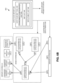
- FIGS 6A and 6B illustrate an example IOT system 600 including a data flow server 640 having a data flow map tool 642 according to various embodiments.
- the IOT system 600 can include a server system 610 having one or more IOT servers configured to implement services, such as a storage service 611, a compute service 612, an artificial intelligence (AI) service 613, a business logic service 614, or the like, for managed devices in the IOT system 600.
- services such as a storage service 611, a compute service 612, an artificial intelligence (AI) service 613, a business logic service 614, or the like, for managed devices in the IOT system 600.
- AI artificial intelligence
- the managed devices in the IOT system 600 can include generic IOT applications 621-623 in an edge system 620 and sensors, actuators, or other peripherals in a sensor system 630.
- the edge system 620 can include one or more IOT edge nodes configured, for example, with a containerized application, to implement the generic IOT applications 621-623.
- the sensor system 630 can gather or generate information, for example, by monitoring one or more devices, and transmit the information to the server system 610 through the edge system 620.
- the sensor system 630 can gather information corresponding to the manufacturing of a product, for example, by identifying operations or operational states of manufacturing equipment, manufacturing lines, the manufacturing of products, inventory, testing or verification procedures for the products, or the like.
- the edge system 620 can facilitate data communication between the server system 610 and the sensor system 630 and, in some embodiments, perform data processing or filtering operations on the data received by the sensor system 630 or the server system 610.
- the edge system 620 can include multiple generic IOT applications 621-623 capable of exchanging data with the server system 610, the sensor system 630, and each other.
- the generic IOT applications 621-623 can include embedded application systems configured, for example, with a containerized application, to implement programmable edge devices capable of being configured to implement data flows between the services 611-614 in the server system 610 and the sensors in the sensor system 630..
- the IOT system 600 can include data flow server 640 to define data flows between the sensor system 630 and the server system 610 through the applications deployed on the edge system 620.
- the data flow map tool 642 in the data flow server 640 can generate one or more data flow maps that define paths from data to traverse the IOT system 600 along with any data processing or filtering for the edge system 620 to perform on the data.
- the data flow map tool 642 can include an environment configuration unit 644 to model the server system 610 by separately modeling the IOT servers in the server system 610 or the services, such as a storage service 611, a compute service 612, an artificial intelligence (AI) service 613, a business logic service 614, or the like, implemented in the server system 610.
- the environment configuration unit 644 can identify endpoints for the IOT servers in the server system 610 or the services in the server system 610. The endpoints can correspond to portions of the IOT servers in the server system 610 or the services capable of exchanging data with the edge system 620.
- the environment configuration unit 644 can model the edge system 620 by separately modeling the generic IOT applications 621-623 by their endpoints and the data processing operations capable of being implemented in the generic IOT applications 621-623.
- the endpoints can correspond to portions of the generic IOT applications 621-623 in the edge system 620 capable of exchanging data with server system 610, the sensor system 630, or other generic IOT applications in the edge system 620.
- the environment configuration unit 644 can model the sensor system 630 by separately modeling the sensors implemented in the sensor system 630 according to a device the sensor monitors, a type of information gathered, or the like. In some embodiments, the environment configuration unit 644 can identify endpoints for the sensors in the in the sensor system 630. The endpoints can correspond to portions of the sensors in the sensor system 630 capable of exchanging data with the edge system 620.
- the data flow map tool 642 can include a map unit 646 to generate one or more data flow maps based on the models of the server system 610, the edge system 620, the generic IOT applications 621-623, and the sensor system 630.
- Each of the data flow maps can describe a configuration for the IOT system 600 and define the data flow through the IOT system 600.
- the data flow maps can utilize the endpoints in the IOT system 600 to link the sensors in the sensor system 630 to one or more of the generic IOT applications 621-623 in the edge system 620, and link the generic IOT applications 621-623 in the edge system 620 to each other or to one or more IOT servers or services in the server system 610.
- the data flow maps can identify a direction for the flow of data, for example, from a sensor-to-edge node-to-server, along with any active data processing, transformation, manipulation, filtering operations, or the like, to be performed on the data by one or more of generic IOT applications 621-623 in the data flow.
- the map unit 646 can generate a data flow map presentation 641 that can display the models of the sensors, IOT servers or services, and generic IOT applications 621-623 in the IOT system 600.
- the data flow server 640 in response to user input, can link the models in the IOT system 600, for example, endpoint-to-endpoint, and define data processing operations to generate the data flow maps.
- the data flow map tool 642 can include a deployment unit 648 to prompt the IOT system 600 to implement a configuration corresponding to at least one of the data flow maps.
- the deployment unit 648 can configure the generic IOT applications 621-623, the sensor system 630, and the server system services 611-614 to form an interconnect for the exchange of data between the server system 610 and the sensor system 630 and, optionally, to process data received in a data flow.
- the IOT system 650 is similar to the IOT system 600 described in Figure 6A except the data flow server 640 has deployed an example data flow map into the IOT system 650.
- the deployment unit 648 can generate a configuration deployment 643 based on the example data flow map and provide the configuration deployment 643 to the edge system 620, the configured IOT applications 624-626, the sensor system 630, and the server system services 611-614.
- the generic IOT applications 621-623 in Figure 6A can receive the configuration deployment 643 from the data flow map tool 640, which can configure the generic IOT applications 621-623 according to the example data flow map into the configured IOT applications 624-626.
- the sensors in the sensor system 630 also can receive the configuration deployment 643 from the data flow server 640, which can configure the sensors according to the example data flow map.
- the configuration of the edge system 620 and the sensor system 630 with the configuration deployment 643 can allow the sensor system 630 to communicate with the server system 610 via the edge system 620 and, optionally, for the edge system 620 to perform data processing operations on the data exchanged between the sensor system 630 and the server system 610.
- the data flow server 640 can re-configure the IOT system 650 by transmitting a new configuration deployment 643 corresponding to a different data flow map developed by the map unit 646.
- the data flow server 640 can store many different data flow maps, which each describe a different configuration of the modeled IOT system 6600 in Figure 6A . This deployment and re-deployment of data flow maps onto the IOT system 650 may prompt a fast re-configuration of the IOT system 650 relative to a conventional process of stopping application and re-deploying a new set of applications.
- the data flow server 640 can configure and re-configure the IOT system 650 to implement multiple different data flows without having to hardcode the data flows into the sensor system 630 and the edge system 620.
- FIG. 7 illustrates an example flowchart for implementation of a data flow map to configure an IOT system according to various embodiments.
- a computing system implementing a data flow map tool can deploy containerized applications to edge nodes in an edge system.
- the edge nodes can include embedded application systems to implement Docker engines for executing container images, for example, standalone, executable embedded applications, which can include executable code, runtime, system tools, system libraries, settings, or the like, utilized by the Docker engines to implement the embedded applications corresponding to the container images.
- the edge node can execute the container image to implement a configurable IOT application capable of further configuration, for example, by a data flow server.
- the computing system implementing the data flow map tool can model endpoints of configurable IOT applications in an edge system, sensors, actuators, or other peripherals in a sensor system, and servers in a server environment.
- the data flow map tool can model the server system by identifying endpoints for IOT servers or the services in the server system and then separately modeling IOT servers or services, such as a storage service, a compute service, an artificial intelligence (AI) service, a business logic service, or the like, based on their endpoints.
- the endpoints can correspond to portions of the IOT servers in the server system or the services capable of exchanging data with the edge system.
- the data flow map tool can model the edge system by identifying endpoints of the configurable IOT applications hosted by one or more edge nodes in the edge system, identifying data processing capabilities in the configurable IOT applications, and separately modeling the configurable IOT applications by their endpoints and the data processing capabilities.
- the endpoints can correspond to portions of the configurable IOT applications capable of exchanging data with server system, the sensor system, or other configurable IOT applications hosted by one or more edge nodes in the edge system.
- the data flow map tool can model the sensor system by separately modeling the sensors implemented in the sensor system according to a device the sensor monitors, a type of information gathered, or the like.
- the environment configuration unit can identify endpoints for the sensors in the in the sensor system. The endpoints can correspond to portions of the sensors in the sensor system capable of exchanging data with the edge system.
- the computing system implementing the data flow map tool can develop a data flow map that defines a configuration for the configurable IOT applications and defines connectivity between the modeled endpoints.
- the data flow map tool can develop the data flows between the server system and the sensor system via the edge system, which can include endpoint-to-endpoint links between the configurable IOT applications and sensors, other configurable IOT applications, and/or servers along with a description of the data processing operations to be performed by the configurable IOT applications.
- the data flows defined by the data flow map tool can be implemented into a data flow map, which can describe a configuration for the sensors, configurable IOT applications, and servers, which can implement the data flows developed by the data flow map tool.
- the computing system implementing the data flow map tool can configure the edge system and the sensor system, which can implement the connectivity in the data flow map.
- the data flow map tool can transmit a deployment configuration to the sensor system, which can prompt the sensors to output gathered data at a particular endpoint for transmission to a particular configurable IOT application.
- the data flow map tool also can transmit a deployment configuration to the edge system, which can prompt the configurable IOT applications to exchange data via particular endpoints with sensors, server, and/or configurable IOT applications.
- the deployment configuration also can program the configurable IOT applications to implement one or more data processing algorithms, for example, to filter or manipulate data exchanged between the server system and the sensor system.
- the system and apparatus described above may use dedicated processor systems, micro controllers, programmable logic devices, microprocessors, or any combination thereof, to perform some or all of the operations described herein. Some of the operations described above may be implemented in software and other operations may be implemented in hardware. Any of the operations, processes, and/or methods described herein may be performed by an apparatus, a device, and/or a system substantially similar to those as described herein and with reference to the illustrated figures.
- the processing device may execute instructions or "code" stored in memory.
- the memory may store data as well.
- the processing device may include, but may not be limited to, an analog processor, a digital processor, a microprocessor, a multi-core processor, a processor array, a network processor, or the like.
- the processing device may be part of an integrated control system or system manager, or may be provided as a portable electronic device configured to interface with a networked system either locally or remotely via wireless transmission.
- the processor memory may be integrated together with the processing device, for example RAM or FLASH memory disposed within an integrated circuit microprocessor or the like.
- the memory may comprise an independent device, such as an external disk drive, a storage array, a portable FLASH key fob, or the like.
- the memory and processing device may be operatively coupled together, or in communication with each other, for example by an I/O port, a network connection, or the like, and the processing device may read a file stored on the memory.
- Associated memory may be "read only" by design (ROM) by virtue of permission settings, or not.
- Other examples of memory may include, but may not be limited to, WORM, EPROM, EEPROM, FLASH, or the like, which may be implemented in solid state semiconductor devices.
- Other memories may comprise moving parts, such as a known rotating disk drive. All such memories may be "machine-readable” and may be readable by a processing device.
- Operating instructions or commands may be implemented or embodied in tangible forms of stored computer software (also known as "computer program” or “code”).
- Programs, or code may be stored in a digital memory and may be read by the processing device.
- “Computer-readable storage medium” (or alternatively, “machine-readable storage medium”) may include all of the foregoing types of memory, as well as new technologies of the future, as long as the memory may be capable of storing digital information in the nature of a computer program or other data, at least temporarily, and as long at the stored information may be “read” by an appropriate processing device.
- the term “computer-readable” may not be limited to the historical usage of "computer” to imply a complete mainframe, mini-computer, desktop or even laptop computer.
- “computer-readable” may comprise storage medium that may be readable by a processor, a processing device, or any computing system.
- Such media may be any available media that may be locally and/or remotely accessible by a computer or a processor, and may include volatile and non-volatile media, and removable and non-removable media, or any combination thereof.
- a program stored in a computer-readable storage medium may comprise a computer program product.
- a storage medium may be used as a convenient means to store or transport a computer program.
- the operations may be described as various interconnected or coupled functional blocks or diagrams. However, there may be cases where these functional blocks or diagrams may be equivalently aggregated into a single logic device, program or operation with unclear boundaries.
Landscapes
- Engineering & Computer Science (AREA)
- Computer Networks & Wireless Communication (AREA)
- Signal Processing (AREA)
- Computing Systems (AREA)
- Health & Medical Sciences (AREA)
- General Health & Medical Sciences (AREA)
- Medical Informatics (AREA)
- Computer Security & Cryptography (AREA)
- Business, Economics & Management (AREA)
- General Business, Economics & Management (AREA)
- Computer And Data Communications (AREA)
Description
- This application is generally related to Internet of Things (IOT) technology and, more specifically, to centralized management of data flow maps for distributed edge node deployment.
- Many industries have implemented Internet of Things (IOT) technology, which can connect machinery, sensors, control systems, or the like, in an industrial environment, to computers for remote monitoring and control. Many of the machines, sensors, and control systems in the industrial environment can have external interfaces to output information corresponding to their operations to a server via an edge node acting as a protocol translator for transmissions between the industrial environment and the server. For example, specially-programmed edge node can receive the information output from the machines, sensors, and control systems in the industrial environment in one transmission protocol, filter or aggregate the data received from the machines, sensors, and control systems in an attempt to reduce the volume of data uploaded to the server for subsequent processing, and transmit the information to the server with a different transmission protocol.
- Each data flow from the external interfaces of the machines, sensors, and control systems in the industrial environment to the server through one or more edge nodes typically include custom configurations. For example the machines, sensors, and control systems in the industrial environment can include custom logic to output data at an external interface using a particular protocol, while the edge nodes can be specially-programmed or hard-coded in static flows, for example, performing data compression, data transformation, such as fast Fourier Transform operations, feature extraction, data combination from various sources, such as data convolution. These customized data flows are hardcoded in the industrial environment to enable the transmission of data from the machines, sensors, and control systems to the server. Hardcoding the data flows into the edge nodes, machines, sensors, and control system is time consuming and renders the overall industrial environment inflexible and difficult to scale.
- Document
US 2020/084113 A1 discloses a method for a contextual transformation of an analytical model for an industrial internet of things (IIoT) edge node. For instance, the analytical model is received from a cloud service, local data of the IIoT edge node is obtained, and the local data is analyzed to determine a situational context of the IIoT edge node. - Document
US 2018/338017 A1 discloses a method to compress, aggregate and archive Internet of Things data originating from sensors can use a point cloud based geometric data model and a distribution and aggregation method based on compressed point cloud representations. - Document
US 2020/112490 A1 discloses a framework for dynamic management of analytic functions such as data processors and machine learned ("ML") models for an Internet of Things intelligent edge that addresses management of the lifecycle of the analytic functions from creation to execution, in production. The end user will be seamlessly able to check in an analytic function, version it, deploy it, evaluate model performance and deploy refined versions into the data flows at the edge or core dynamically for existing and new end points. The framework comprises a hypergraph-based model as a foundation, and may use a microservices architecture with the ML infrastructure and models deployed as containerized microservices. - The present invention is defined by the enclosed claims. This application discloses a method, a computer program product and an apparatus, such as a computing system, to generate models of managed devices and applications in an Internet of Things (IOT) system by identifying each endpoint in the managed devices and applications capable of transmitting or receiving the data and defining flows for data from the endpoints in sensors to endpoints of IOT servers via endpoints of the programmable edge device applications. The computing system can develop a data flow map to define a connectivity of the programmable edge device applications to the sensors and the servers in the IOT system for exchanging the data from the sensors to the servers in the IOT system via the programmable edge device applications. The computing system can prompt configuration of the managed devices and applications in the IOT system based on the data flow map, which implements the connectivity of the programmable edge device applications to the sensors and to servers in the IOT system. Embodiments will be described in greater detail below.
-
-
Figures 1 and2 illustrate an example of a computer system of the type that may be used to implement various embodiments. -
Figure 3 illustrates an example of an Internet of Things (IOT) system implemented in a server environment and an on-premises environment according to various embodiments. -
Figure 4 illustrates an example of an application manager in an IOT server according to various embodiments. -
Figure 5 illustrates an example of an IOT edge node according to various embodiments. -
Figures 6A and6B illustrate an example IOT system including a data flow server having a data flow map tool according to various embodiments. -
Figure 7 illustrates an example flowchart for implementation of a data flow map to configure an IOT system according to various embodiments. - Various embodiments may be implemented through the execution of software instructions by a
computing device 101, such as a programmable computer. Accordingly,Figure 1 shows an illustrative example of acomputing device 101. As seen in this figure, thecomputing device 101 includes acomputing unit 103 with aprocessing unit 105 and asystem memory 107. Theprocessing unit 105 may be any type of programmable electronic device for executing software instructions, but will conventionally be a microprocessor. Thesystem memory 107 may include both a read-only memory (ROM) 109 and a random access memory (RAM) 111. As will be appreciated by those of ordinary skill in the art, both the read-only memory (ROM) 109 and the random access memory (RAM) 111 may store software instructions for execution by theprocessing unit 105. - The
processing unit 105 and thesystem memory 107 are connected, either directly or indirectly, through abus 113 or alternate communication structure, to one or more peripheral devices 117-123. For example, theprocessing unit 105 or thesystem memory 107 may be directly or indirectly connected to one or more additional memory storage devices, such as ahard disk drive 117, which can be magnetic and/or removable, a removable optical disk drive 119, and/or a flash memory card. Theprocessing unit 105 and thesystem memory 107 also may be directly or indirectly connected to one ormore input devices 121 and one ormore output devices 123. Theinput devices 121 may include, for example, a keyboard, a pointing device (such as a mouse, touchpad, stylus, trackball, or joystick), a scanner, a camera, and a microphone. Theoutput devices 123 may include, for example, a monitor display, a printer and speakers. With various examples of thecomputing device 101, one or more of the peripheral devices 117-123 may be internally housed with thecomputing unit 103. Alternately, one or more of the peripheral devices 117-123 may be external to the housing for thecomputing unit 103 and connected to thebus 113 through, for example, a Universal Serial Bus (USB) connection. - With some implementations, the
computing unit 103 may be directly or indirectly connected to anetwork interface 115 for communicating with other devices making up a network. Thenetwork interface 115 can translate data and control signals from thecomputing unit 103 into network messages according to one or more communication protocols, such as the transmission control protocol (TCP) and the Internet protocol (IP). Also, thenetwork interface 115 may employ any suitable connection agent (or combination of agents) for connecting to a network, including, for example, a wireless transceiver, a modem, or an Ethernet connection. Such network interfaces and protocols are well known in the art, and thus will not be discussed here in more detail. - It should be appreciated that the
computing device 101 is illustrated as an example only, and it not intended to be limiting. Various embodiments may be implemented using one or more computing devices that include the components of thecomputing device 101 illustrated inFigure 1 , which include only a subset of the components illustrated inFigure 1 , or which include an alternate combination of components, including components that are not shown inFigure 1 . For example, various embodiments may be implemented using a multi-processor computer, a plurality of single and/or multiprocessor computers arranged into a network, or some combination of both. - With some implementations, the
processor unit 105 can have more than one processor core. Accordingly,Figure 2 illustrates an example of amulti-core processor unit 105 that may be employed with various embodiments. As seen in this figure, theprocessor unit 105 includes a plurality ofprocessor cores processor core computing engine memory cache computing engine computing engine corresponding memory cache - Each
processor core interconnect 207. The particular construction of theinterconnect 207 may vary depending upon the architecture of theprocessor unit 105. With someprocessor cores interconnect 207 may be implemented as an interconnect bus. Withother processor units interconnect 207 may be implemented as a system request interface device. In any case, theprocessor cores interconnect 207 with an input/output interface 209 and amemory controller 210. The input/output interface 209 provides a communication interface to thebus 113. Similarly, thememory controller 210 controls the exchange of information to thesystem memory 107. With some implementations, theprocessor unit 105 may include additional components, such as a high-level cache memory accessible shared by theprocessor cores Figure 1 andFigure 2 is provided as an example only, and it not intended to suggest any limitation as to the scope of use or functionality of alternate embodiments. -
Figure 3 illustrates an example of an Internet of Things (IOT)system 300 implemented in aserver environment 301 and an on-premises environment 302 according to various embodiments. Referring toFigure 3 , the on-premises environment 302 of theIOT system 300 can include multiple sensor systems 330-1 to 300-N, each including one or more sensors or other devices capable of communicating with one or more IOT edge nodes 500-1 to 500-N. In some embodiments, the sensor system 330-1 can communicate with the IOT edge node 500-1, the sensor system 330-2 can communicate with the IOT edge node 500-2, and the sensor system 330-N can communicate with the IOT edge node 500-N. In other embodiments, one or more of the sensor systems 330-1 to 330-N can communicate with any of the IOT edge nodes 500-1 to 500-N and, as will be described below in greater detail, be configured (and dynamically reconfigured) by adata flow server 340 to communicate with various embedded applications hosted in the IOT edge nodes 500-1 to 500-N. - In a manufacturing environment, such as a factory floor or multiple distributed factories, the sensors in the sensor systems 330-1 to 330-N can gather information corresponding to the manufacturing of a product, for example, by identifying operations or operational states of manufacturing equipment, manufacturing lines, the manufacturing of products, inventory, testing or verification procedures for the products, or the like. The sensors in the sensor systems 330-1 to 330-N can transmit the gathered information towards an
IOT server 310 via one or more of the IOT edge nodes 500-1 to 500-N. - The TOT edge nodes 500-1 to 500-N can include embedded application systems 510-1 to 510-N, respectively, to process the information received from the sensor systems 330-1 to 330-N. The embedded application systems 510-1 to 510-N can determine states of the machinery, manufacturing lines, equipment, products, inventory, or the like, based on the information received from the sensor system 330-1 to 330-N. The embedded application systems 510-1 to 510-N can generate messages based on the determined states and transmit the messages to the
IOT server 310. - In some embodiments, the embedded application systems 510-1 to 510-N, in the IOT edge nodes 500-1 to 500-N, respectively, can be generic or programmable with regard to the data flow from the sensor system 330-1 to 330-N to the
IOT server 310. Thedata flow server 340 can deploy a configuration, for example, from a data flow map, to the IOT edge nodes 500-1 to 500-N, which can configure the embedded application system 510-1 to 510-N to implement a data flow from the sensor system 330-1 to 330-N to theIOT server 310. Thedata flow server 340 also can update the configuration of the IOT edge nodes 500-1 to 500-N to implement different data flows from the sensor system 330-1 to 330-N to theIOT server 310, for example, based on a different data flow map. Embodiments will be described below in greater detail. - The IOT edge nodes 500-1 to 500-N can include a processing systems configured to execute instructions corresponding to embedded applications, which can prompt the processing systems to analyze the information received from the sensor systems 330-1 to 330-N, generate the messages, and transmit the messages to the
IOT server 310. In some embodiments, the IOT edge nodes 500-1 to 500-N can receive the embedded applications as container images from theIOT server 310 located in theserver environment 301. The embedded application systems 510-1 to 510-N can implement Docker engines to execute the container images. The container images can be standalone, executable embedded applications, which can include executable code, runtime, system tools, system libraries, settings, or the like, utilized by the Docker engines to implement the embedded applications corresponding to the container images. - The
IOT server 310 can include anapplication manager 400 to deploy containers having container images to the IOT edge nodes 500-1 to 500-N. In some embodiments, theapplication manager 400 can select an embedded application to implement in one of the IOT edge nodes 500-1 to 500-N, for example, from anapplication repository 320 located in theserver environment 301, and generate a container to deploy the selected embedded application to the corresponding IOT edge nodes 500-1 to 500-N. The addition of embedded application systems 510-1 to 510-N to the IOT edge nodes 500-1 to 500-N, respectively, can allow for deployment of the containers and corresponding container images by theapplication manager 400 to the IOT edge nodes 500-1 to 500-N, which can allow theIOT server 310 to centrally control a flow of information gathered by the sensor systems 330-1 to 330-N to theIOT server 310. - The
application manager 400 in theIOT server 310 also can orchestrate various operations performed by the embedded application systems 510-1 to 510-N in the IOT edge nodes 500-1 to 500-N, respectively. For example, theapplication manager 400 can utilize the embedded application systems 510-1 to 510-N to off-load processing from theserver environment 301 to the IOT edge nodes 500-1 to 500-N in the on-premises environment 302. In some embodiments, theapplication manager 400 in theIOT server 310 can identify processing and/or memory resources in the IOT edge nodes 500-1 to 500-N that remain after implementing container images for the communication of information gathered by the sensor systems 330-1 to 330-N. Theapplication manager 400 can utilize the remaining processing and/or memory resources in the IOT edge nodes 500-1 to 500-N to off-load processing from theserver environment 301 to the on-premises environment 302. For example, the application manager 40 can select an embedded application from theapplication repository 320 corresponding to the operations to be off-loaded to the IOT edge nodes 500-1 to 500-N and deploy a container that includes the embedded application to the corresponding IOT edge nodes 500-1 to 500-N. - In another example, the
application manager 400 also can orchestrate the import or export of parameters in the embedded application implemented by the embedded application systems 510-1 to 510-N. The parameters in the embedded application can correspond to values coded in the embedded application or values determined by the embedded application during execution. For example, when the embedded application corresponds to a temperature monitoring application that utilizes a temperature reading from a sensor to determine a rate of temperature change over a preset time period and then generates a message when the rate of temperature change exceeds a threshold value, the parameters can correspond to the rate of temperature change and the threshold value. In this example, theapplication manager 400 can send a parameter message to one of the IOT edge nodes 500-1 to 500-N implementing the temperature monitoring application, which can include a parameter for the corresponding embedded application systems 510-1 to 510-N to import into the temperature monitoring application, such as a parameter corresponding to a different threshold value. Theapplication manager 400 also can send a parameter message to one of the IOT edge nodes 500-1 to 500-N implementing the temperature monitoring application, which can prompt the corresponding embedded application systems 510-1 to 510-N to export a parameter from the temperature monitoring application, such as a parameter corresponding to a threshold value or the rate of temperature change. - The
application manager 400 also can orchestrate the import or export of parameters in the embedded application by implementing an avatar of the embedded application running on the embedded application systems 510-1 to 510-N and then transmitting parameter messaging to the embedded application systems 510-1 to 510-N. In some embodiments, the parameter messaging can prompt the embedded application systems 510-1 to 510-N to import a parameter from theIOT server 310, which can allow the application manager 40 to modify the embedded application implemented by one or more of embedded application systems 510-1 to 510-N without having to deploy a different embedded application to the IOT edge nodes 500-1 to 500-N. - The parameter messaging also can prompt the embedded application systems 510-1 to 510-N to import or export parameters to other devices, such as other IOT edge nodes 500-1 to 500-N. The
application manager 400 can orchestrate the sharing of parameters across the distributed IOT edge nodes 500-1 to 500-N with the parameter messaging, which can allow the IOT edge nodes 500-1 to 500-N to operate in conjunction with each other. Embodiments of the application manager and the embedded application system will be described below in greater detail. -
Figure 4 illustrates an example of anapplication manager 400 in an IOT server according to various embodiments. Referring toFigure 4 , the IOT server including theapplication manager 400 can be located in a server environment and be configured to communicate with devices located in an on-premises environment or in a different server environment. Theapplication manager 400 can include an embeddedapplication deployment unit 410 to select embedded applications for deployment on IOT edge nodes in an on-premises environment. In some embodiments, theapplication manager 400 can select the embedded applications based on input received from a remote user terminal or based on an internal programming. Theapplication manager 400 can retrieve a container image corresponding to the selected embedded application from a memory device, such as an application repository located in the server environment or another memory system storing container images accessible by the IOT server. - The embedded
application deployment unit 410 can include a containerizedIOT application unit 412 to generate acontainer 401 that includes the container image corresponding to the selected embedded application. The containerizedIOT application unit 412 can transmit thecontainer 401 towards the IOT edge node over a communication network, such as packet-switched network, a circuit-switched network, a combination thereof, or the like. The IOT edge node can extract the container image from the receivedcontainer 401 and execute the container image, for example, with a Docker engine or the like, to implement the embedded application on the IOT edge node. - The implementation of the embedded application can prompt the IOT edge node to generate
application messages 402, which the IOT edge node can transmit to the IOT server over the communication network. Theapplication messages 402 can include information the IOT edge nodes generated, aggregated, filtered, or the like, in response to the execution of the embedded application corresponding to the container image. For example, when the IOT edge node receives industrial measurement data, theapplication messaging 402 can include a subset of the industrial measurement data, an aggregated report of the industrial measurement data, an indication that the IOT edge node detected an event from industrial measurement data, or the like. - The embedded
application deployment unit 410 can include an embeddedapplication state unit 414 to model states of the embedded applications deployed on IOT edge nodes based, at least in part, on theapplication messages 402 received from the IOT edge nodes. The embeddedapplication state unit 414 can model the states of the embedded application by storing instances of container images capable of being deployed by theapplication manager 400, instances of container images having been deployed, identifiers of IOT edge nodes having been commissioned to receive container images from theapplication manager 400, parameters supported by the container images, values of the parameters supported by the container images, or the like. The embeddedapplication state unit 414 can update the model of the embedded applications on the IOT edge nodes when a new container image has been deployed to or released from an IOT edge node, based on contents of theapplication messages 402 from the IOT edge nodes implementing the embedded applications, or the like. In some embodiments, the model of the embedded application can correspond to an avatar of the deployed container images on the IOT edge nodes, which can mimic the operational states of the deployed container images as implemented on the IOT edge nodes. For example, when an IOT edge node implements a sound classification embedded application, the embeddedapplication state unit 414 can generate a model of the sound classification embedded application that identifies the IOT edge node, identifies the sound classification embedded application has been deployed on the IOT edge node, identifies the parameters associated with the sound classification embedded application, identifies the values of the parameters, or the like. - The
application manager 400 can include a publish-subscribe unit 420 to generateparameter messaging 403, which can prompt the IOT edge nodes to import or export parameters associated with embedded applications implemented by the IOT edge nodes. Since the embeddedapplication state unit 414 can include a model of the embedded application deployed in the IOT edge node, the publish-subscribe unit 420 can generateparameter messaging 403 to import or export parameters associated with the embedded application. In some embodiments, the publish-subscribe unit 420 can include parameter values in theparameter messaging 403 and the IOT edge nodes can import the parameter values into the embedded applications. The ability to import of parameter values into the embedded applications can allow the IOT server to remotely modify a deployed container image without having to release the already deployed container image and deploy anew container 401 with a modified container image. - The publish-
subscribe unit 420 can generateparameter messaging 403 that, when provided to the IOT edge node, can prompt the IOT edge node to export a parameter value asapplication parameters 404. The IOT edge node can transmit theapplication parameters 404 to theapplication manager 400 in the IOT server, which can utilize the parameter values to update the model of the embedded application. In some embodiments, the publish-subscribe unit 420 can retransmit theapplication parameters 404 to a different networking device or server platform, for example, to a networking device subscribed to receive the parameter value(s) exported from the IOT edge node in theapplication parameters 404. In some embodiments, theparameter messaging 403 can specify where the IOT edge node should export theapplication parameters 404, for example, identify a networking device to receive theapplication parameters 404. The publish-subscribe unit 420 may utilize the models of the embedded applications to identify and track which parameter values to export from which embedded applications and which networking devices, such as other IOT edge nodes subscribe to receive the parameter values. The publish-subscribe unit 420 can generate theparameter messaging 403 to prompt an import of parameters from the embedded applications implemented on the IOT edge nodes, to prompt an export of parameters from the embedded applications implemented on the IOT edge nodes, to prompt the embedded applications implemented on the IOT edge nodes share parameters between themselves, or the like. - The
application manager 400 can include a distributedresource utilization unit 430 to utilize multiple distributed IOT edge nodes to implement complex services, for example, by coordinating the deployment ofcontainers 401 to the IOT edge nodes, while utilize the models of the deployed embedded applications along with the publish-subscribe technology to have the embedded applications communicate with each other across the distributed IOT edge nodes. By modeling the states of the embedded applications and coordinating the sharing of parameter values across distributed IOT edge nodes, theapplication manager 400 can direct the distributed IOT edge nodes to implement complex computing tasks or provide complex services, for example, unable to be performed by an individual IOT edge node. - In some embodiments, the distributed
resource utilization unit 430 can off-load processing from the server environment to one or more of the IOT edge nodes in the on-premises environment. In some embodiments, theapplication manager 400 in the IOT server can identify available processing and/or memory resources in the IOT edge nodes, deploycontainers 401 having container images that, when executed by the IOT edge nodes having available processing and/or memory resources, can perform the off-loaded processing from the server environment. The distributedresource utilization unit 430 can work in conjunction with the embeddedapplication state unit 414 and the publish-subscribe unit 420 to enable multiple IOT edge nodes implementing the off-loaded processing to communicate parameters with each other. When multiple IOT edge nodes implement the off-loaded processing, the distributedresource utilization unit 430 can utilize the embeddedapplication state unit 414 to generate models for the embedded applications to implement the off-loaded processing, and utilize the publish-subscribe unit 420 to configureparameter messaging 403 prompting exchange of parameters between the IOT edge nodes in order to accomplish their processing tasks. -
Figure 5 illustrates an example of anIOT edge node 500 with multiple deployed embedded applications according to various embodiments. Referring toFigure 5 , theIOT edge node 500 can include acontainer manager 521 to receivecontainers 501 from an IOT server, for example, located in a server environment. Thecontainers 501 can include container images corresponding to embedded applications for deployment on theIOT edge node 500. Thecontainer manager 521 can provide the containers toDocker daemon 530 in theIOT edge node 500, which can implement a Docker engine and execute the container images in thecontainers 501 to realize the embedded applications. - In the instant example, the
Docker daemon 530 can have a Docker engine capable of supporting embedded applications corresponding tomultiple containers container 531, when implemented by theDocker daemon 530, can execute a container image and implement anapplication controller 532. Thecontainer 531 also can include acontrol agent 533 to communicateparameters 502 associated with theapplication controller 532 to the IOT server via anapplication manager 522. In some embodiments, thecontrol agent 533 can include a messaging application to communicate with theapplication manager 522 to import and export parameter values associated with thecontainer 531 and theapplication controller 532. Thecontainer 534, when implemented by theDocker daemon 530, can execute a container image and implement anapplication broker 535. Thecontainer 534 also can include acontrol agent 536 to communicateparameters 502 associated with theapplication broker 535 to the IOT server via theapplication manager 522. In some embodiments, thecontrol agent 536 can include a messaging application to communicate with theapplication manager 522 to import and export parameter values associated with thecontainer 534 and theapplication broker 535. Thecontainer 537, when implemented by theDocker daemon 530, can execute a container image and implement an embeddedapplication 538. Thecontainer 537 also can include acontrol agent 539 to communicateparameters 502 associated with the embeddedapplication 538 to the IOT server via theapplication manager 522. In some embodiments, thecontrol agent 539 can include a messaging application to communicate with theapplication manager 522 to import and export parameter values associated with thecontainer 537 and the embeddedapplication 538. - The
application manager 522 can receive parameter messages from the IOT server, for example, requesting to import orexport parameters 502 from thecontainers application manager 522 can identify which of thecontainers control agents containers control agents control agents parameter 502 in response to the parameter messages. In some embodiments, thecontrol agents parameters 502 to theapplication manager 522 for transmission to the IOT server in response to the parameter messages, for example, implementing a "commit" logic typically utilized for process control. Thecontrol agents application controller 532 or embeddedapplication 538, to exportparameters 502 to a networking device, such as the IOT server, a different IOT edge node, a server environment, or the like. - The
IOT edge node 500 can include amote manager 523 to communicate with a sensor system, for example, having one or more sensors, actuators, peripheral nodes performing various operations, such as Artificial Intelligence (AI), or the like, located in an industrial environment. Themote manager 523 can receive messaging from an IOT server, for example, located in a server environment. In some embodiments, the messaging can include configuration data for the sensor system, and themote manager 523 can forward the messaging to the sensor system or prompt the configuration of the sensor system based on the configuration data. Themote manager 523 also can receive information from the sensor system and forward the information to the IOT server, for example, generate messaging that includes the information and transmit the messaging to the IOT server. - The
IOT edge node 500 executing the container images in thecontainers sensor data 503 from the sensor system. Theapplication broker 535 can receive thesensor data 503 from the sensor system and distribute thesensor data 503 to theapplication controller 532 and the embeddedapplication 538. In some embodiments, theapplication controller 532 and the embeddedapplication 538 can be provided the messaging parameters of theapplication broker 535 via publish-subscribe operation. For example, the IOT server can requestparameters 502 associated with the messaging functionality of theapplication broker 535, which can be provided by thecontrol agent 536 to the IOT server. The IOT server can utilize the publish-subscribe functionality to import the messaging parameters of theapplication broker 535 to theapplication controller 532 and the embeddedapplication 538, which can allow theapplication broker 535 to distribute thesensor data 503 to theapplication controller 532 and the embeddedapplication 538. - The
application controller 532 and the embeddedapplication 538 can analyze thesensor data 503 to monitor an industrial environment. When theapplication controller 532 and/or the embeddedapplication 538 detect an event based on the analysis of thesensor data 503, such as a machine malfunction, a temperature change, a detected noise, or the like, theapplication controller 532 and/or the embeddedapplication 538 can generate application messaging for transmission to the IOT server or other networking device. The application messaging can include an indication of the detected event,sensor data 503 corresponding to the detected event, or the like. -
Figures 6A and6B illustrate an example IOT system 600 including adata flow server 640 having a dataflow map tool 642 according to various embodiments. Referring toFigure 6A , the IOT system 600 can include aserver system 610 having one or more IOT servers configured to implement services, such as astorage service 611, acompute service 612, an artificial intelligence (AI)service 613, a business logic service 614, or the like, for managed devices in the IOT system 600. - The managed devices in the IOT system 600 can include generic IOT applications 621-623 in an
edge system 620 and sensors, actuators, or other peripherals in asensor system 630. In some embodiments, theedge system 620 can include one or more IOT edge nodes configured, for example, with a containerized application, to implement the generic IOT applications 621-623. Thesensor system 630 can gather or generate information, for example, by monitoring one or more devices, and transmit the information to theserver system 610 through theedge system 620. In a manufacturing environment, such as a factory floor or multiple distributed factories, thesensor system 630 can gather information corresponding to the manufacturing of a product, for example, by identifying operations or operational states of manufacturing equipment, manufacturing lines, the manufacturing of products, inventory, testing or verification procedures for the products, or the like. - The
edge system 620 can facilitate data communication between theserver system 610 and thesensor system 630 and, in some embodiments, perform data processing or filtering operations on the data received by thesensor system 630 or theserver system 610. Theedge system 620 can include multiple generic IOT applications 621-623 capable of exchanging data with theserver system 610, thesensor system 630, and each other. In some embodiments, the generic IOT applications 621-623 can include embedded application systems configured, for example, with a containerized application, to implement programmable edge devices capable of being configured to implement data flows between the services 611-614 in theserver system 610 and the sensors in thesensor system 630.. - The IOT system 600 can include
data flow server 640 to define data flows between thesensor system 630 and theserver system 610 through the applications deployed on theedge system 620. The dataflow map tool 642 in thedata flow server 640 can generate one or more data flow maps that define paths from data to traverse the IOT system 600 along with any data processing or filtering for theedge system 620 to perform on the data. - The data
flow map tool 642 can include anenvironment configuration unit 644 to model theserver system 610 by separately modeling the IOT servers in theserver system 610 or the services, such as astorage service 611, acompute service 612, an artificial intelligence (AI)service 613, a business logic service 614, or the like, implemented in theserver system 610. In some embodiments, theenvironment configuration unit 644 can identify endpoints for the IOT servers in theserver system 610 or the services in theserver system 610. The endpoints can correspond to portions of the IOT servers in theserver system 610 or the services capable of exchanging data with theedge system 620. - The
environment configuration unit 644 can model theedge system 620 by separately modeling the generic IOT applications 621-623 by their endpoints and the data processing operations capable of being implemented in the generic IOT applications 621-623. The endpoints can correspond to portions of the generic IOT applications 621-623 in theedge system 620 capable of exchanging data withserver system 610, thesensor system 630, or other generic IOT applications in theedge system 620. - The
environment configuration unit 644 can model thesensor system 630 by separately modeling the sensors implemented in thesensor system 630 according to a device the sensor monitors, a type of information gathered, or the like. In some embodiments, theenvironment configuration unit 644 can identify endpoints for the sensors in the in thesensor system 630. The endpoints can correspond to portions of the sensors in thesensor system 630 capable of exchanging data with theedge system 620. - The data
flow map tool 642 can include amap unit 646 to generate one or more data flow maps based on the models of theserver system 610, theedge system 620, the generic IOT applications 621-623, and thesensor system 630. Each of the data flow maps can describe a configuration for the IOT system 600 and define the data flow through the IOT system 600. The data flow maps can utilize the endpoints in the IOT system 600 to link the sensors in thesensor system 630 to one or more of the generic IOT applications 621-623 in theedge system 620, and link the generic IOT applications 621-623 in theedge system 620 to each other or to one or more IOT servers or services in theserver system 610. The data flow maps can identify a direction for the flow of data, for example, from a sensor-to-edge node-to-server, along with any active data processing, transformation, manipulation, filtering operations, or the like, to be performed on the data by one or more of generic IOT applications 621-623 in the data flow. - In some embodiments, the
map unit 646 can generate a dataflow map presentation 641 that can display the models of the sensors, IOT servers or services, and generic IOT applications 621-623 in the IOT system 600. Thedata flow server 640, in response to user input, can link the models in the IOT system 600, for example, endpoint-to-endpoint, and define data processing operations to generate the data flow maps. - The data
flow map tool 642 can include adeployment unit 648 to prompt the IOT system 600 to implement a configuration corresponding to at least one of the data flow maps. As will be described below in greater detail with reference toFigure 6B , thedeployment unit 648 can configure the generic IOT applications 621-623, thesensor system 630, and the server system services 611-614 to form an interconnect for the exchange of data between theserver system 610 and thesensor system 630 and, optionally, to process data received in a data flow. - Referring to
Figure 6B , theIOT system 650 is similar to the IOT system 600 described inFigure 6A except thedata flow server 640 has deployed an example data flow map into theIOT system 650. Thedeployment unit 648 can generate a configuration deployment 643 based on the example data flow map and provide the configuration deployment 643 to theedge system 620, the configured IOT applications 624-626, thesensor system 630, and the server system services 611-614. The generic IOT applications 621-623 inFigure 6A can receive the configuration deployment 643 from the dataflow map tool 640, which can configure the generic IOT applications 621-623 according to the example data flow map into the configured IOT applications 624-626. The sensors in thesensor system 630 also can receive the configuration deployment 643 from thedata flow server 640, which can configure the sensors according to the example data flow map. The configuration of theedge system 620 and thesensor system 630 with the configuration deployment 643 can allow thesensor system 630 to communicate with theserver system 610 via theedge system 620 and, optionally, for theedge system 620 to perform data processing operations on the data exchanged between thesensor system 630 and theserver system 610. - The
data flow server 640 can re-configure theIOT system 650 by transmitting a new configuration deployment 643 corresponding to a different data flow map developed by themap unit 646. In some embodiments, thedata flow server 640 can store many different data flow maps, which each describe a different configuration of the modeled IOT system 6600 inFigure 6A . This deployment and re-deployment of data flow maps onto theIOT system 650 may prompt a fast re-configuration of theIOT system 650 relative to a conventional process of stopping application and re-deploying a new set of applications. By including programmable edge devices, such as the generic IOT applications 621-623 described inFigure 6A , thedata flow server 640 can configure and re-configure theIOT system 650 to implement multiple different data flows without having to hardcode the data flows into thesensor system 630 and theedge system 620. -
Figure 7 illustrates an example flowchart for implementation of a data flow map to configure an IOT system according to various embodiments. Referring toFigure 7 , in ablock 701, a computing system implementing a data flow map tool can deploy containerized applications to edge nodes in an edge system. In some embodiments, the edge nodes can include embedded application systems to implement Docker engines for executing container images, for example, standalone, executable embedded applications, which can include executable code, runtime, system tools, system libraries, settings, or the like, utilized by the Docker engines to implement the embedded applications corresponding to the container images. When an edge node receives a container image corresponding to a programmable edge application, the edge node can execute the container image to implement a configurable IOT application capable of further configuration, for example, by a data flow server. - In a
block 702, the computing system implementing the data flow map tool can model endpoints of configurable IOT applications in an edge system, sensors, actuators, or other peripherals in a sensor system, and servers in a server environment. In some embodiments, the data flow map tool can model the server system by identifying endpoints for IOT servers or the services in the server system and then separately modeling IOT servers or services, such as a storage service, a compute service, an artificial intelligence (AI) service, a business logic service, or the like, based on their endpoints. The endpoints can correspond to portions of the IOT servers in the server system or the services capable of exchanging data with the edge system. - The data flow map tool can model the edge system by identifying endpoints of the configurable IOT applications hosted by one or more edge nodes in the edge system, identifying data processing capabilities in the configurable IOT applications, and separately modeling the configurable IOT applications by their endpoints and the data processing capabilities. The endpoints can correspond to portions of the configurable IOT applications capable of exchanging data with server system, the sensor system, or other configurable IOT applications hosted by one or more edge nodes in the edge system.
- The data flow map tool can model the sensor system by separately modeling the sensors implemented in the sensor system according to a device the sensor monitors, a type of information gathered, or the like. In some embodiments, the environment configuration unit can identify endpoints for the sensors in the in the sensor system. The endpoints can correspond to portions of the sensors in the sensor system capable of exchanging data with the edge system.
- In a block 703, the computing system implementing the data flow map tool can develop a data flow map that defines a configuration for the configurable IOT applications and defines connectivity between the modeled endpoints. The data flow map tool can develop the data flows between the server system and the sensor system via the edge system, which can include endpoint-to-endpoint links between the configurable IOT applications and sensors, other configurable IOT applications, and/or servers along with a description of the data processing operations to be performed by the configurable IOT applications. The data flows defined by the data flow map tool can be implemented into a data flow map, which can describe a configuration for the sensors, configurable IOT applications, and servers, which can implement the data flows developed by the data flow map tool.
- In a block 704, the computing system implementing the data flow map tool can configure the edge system and the sensor system, which can implement the connectivity in the data flow map. In some embodiments, the data flow map tool can transmit a deployment configuration to the sensor system, which can prompt the sensors to output gathered data at a particular endpoint for transmission to a particular configurable IOT application. The data flow map tool also can transmit a deployment configuration to the edge system, which can prompt the configurable IOT applications to exchange data via particular endpoints with sensors, server, and/or configurable IOT applications. In some embodiments, the deployment configuration also can program the configurable IOT applications to implement one or more data processing algorithms, for example, to filter or manipulate data exchanged between the server system and the sensor system. Once configured with the deployment configuration, the sensor system, the edge system, and the server system can implement the data flows defined in the data flow map.
- The system and apparatus described above may use dedicated processor systems, micro controllers, programmable logic devices, microprocessors, or any combination thereof, to perform some or all of the operations described herein. Some of the operations described above may be implemented in software and other operations may be implemented in hardware. Any of the operations, processes, and/or methods described herein may be performed by an apparatus, a device, and/or a system substantially similar to those as described herein and with reference to the illustrated figures.
- The processing device may execute instructions or "code" stored in memory. The memory may store data as well. The processing device may include, but may not be limited to, an analog processor, a digital processor, a microprocessor, a multi-core processor, a processor array, a network processor, or the like. The processing device may be part of an integrated control system or system manager, or may be provided as a portable electronic device configured to interface with a networked system either locally or remotely via wireless transmission.
- The processor memory may be integrated together with the processing device, for example RAM or FLASH memory disposed within an integrated circuit microprocessor or the like. In other examples, the memory may comprise an independent device, such as an external disk drive, a storage array, a portable FLASH key fob, or the like. The memory and processing device may be operatively coupled together, or in communication with each other, for example by an I/O port, a network connection, or the like, and the processing device may read a file stored on the memory. Associated memory may be "read only" by design (ROM) by virtue of permission settings, or not. Other examples of memory may include, but may not be limited to, WORM, EPROM, EEPROM, FLASH, or the like, which may be implemented in solid state semiconductor devices. Other memories may comprise moving parts, such as a known rotating disk drive. All such memories may be "machine-readable" and may be readable by a processing device.
- Operating instructions or commands may be implemented or embodied in tangible forms of stored computer software (also known as "computer program" or "code"). Programs, or code, may be stored in a digital memory and may be read by the processing device. "Computer-readable storage medium" (or alternatively, "machine-readable storage medium") may include all of the foregoing types of memory, as well as new technologies of the future, as long as the memory may be capable of storing digital information in the nature of a computer program or other data, at least temporarily, and as long at the stored information may be "read" by an appropriate processing device. The term "computer-readable" may not be limited to the historical usage of "computer" to imply a complete mainframe, mini-computer, desktop or even laptop computer. Rather, "computer-readable" may comprise storage medium that may be readable by a processor, a processing device, or any computing system. Such media may be any available media that may be locally and/or remotely accessible by a computer or a processor, and may include volatile and non-volatile media, and removable and non-removable media, or any combination thereof.
- A program stored in a computer-readable storage medium may comprise a computer program product. For example, a storage medium may be used as a convenient means to store or transport a computer program. For the sake of convenience, the operations may be described as various interconnected or coupled functional blocks or diagrams. However, there may be cases where these functional blocks or diagrams may be equivalently aggregated into a single logic device, program or operation with unclear boundaries.
- While the application describes specific examples of carrying out embodiments, those skilled in the art will appreciate that there are numerous variations and permutations of the above described systems and techniques that fall within the scope of the invention as set forth in the appended claims.
- One of skill in the art will also recognize that the concepts taught herein can be tailored to a particular application in many other ways. In particular, those skilled in the art will recognize that the illustrated examples are but one of many alternative implementations that will become apparent upon reading this disclosure.
- Although the specification may refer to "an", "one", "another", or "some" example(s) in several locations, this does not necessarily mean that each such reference is to the same example(s), or that the feature only applies to a single example.
Claims (13)
- A method comprising:generating, by a computing system, models of managed devices in an Internet of Things, IOT, system (300), wherein the managed devices include one or more edge devices hosting programmable edge device applications and sensors configured to output data towards one or more servers in the IOT system (300);developing, by the computing system, a data flow map to define a connectivity of the programmable edge device applications to the sensors and the servers in the IOT system (300) for exchanging the data from the sensors to the servers in the IOT system (300) via the programmable edge device applications; andprompting, by the computing system, configuration of the programmable edge device applications in the IOT system (300) based on the data flow map, which implements the connectivity of the programmable edge device applications to the sensors and to servers in the IOT system (300);wherein generating the models of the managed devices in the IOT system (300) includes identifying each endpoint in the programmable edge device applications capable of transmitting or receiving the data and defining flows for the data from the endpoints of the sensors to the endpoints of the IOT servers (310) via the endpoints of the programmable edge device applications.
- The method of claim 1, wherein the data flow map is configured to define data processing applications for the programmable edge device applications to implement, and wherein prompting the configuration of the programmable edge device applications in the IOT system (300) based on the data flow map includes deploying the data processing applications onto the programmable edge device applications based on the data flow map.
- The method of claim 1, wherein the sensors are configured to monitor manufacturing equipment to obtain the data, which the sensors output towards the servers in the IOT system (300).
- The method of claim 1, wherein the programmable edge device applications correspond to remote edge node devices having been configured with an embedded application allowing for configuration of the device applications according to the data flow map.
- The method of claim 4, wherein at least one of the servers (340, 640) is configured to deploy the embedded applications to the remote edge node devices, and wherein the embedded application, when executed by the remote edge node devices, prompts the remote edge node devices to implement the programmable edge device applications.
- The method of claim 4, wherein the remote edge node devices include one or more processing devices configured to implement Docker engines to execute the embedded applications.
- An apparatus comprising at least one memory device storing instructions configured to cause one or more processing devices to perform operations comprising:generating models of managed devices in an Internet of Things, IOT, system (300), wherein the managed devices include one or more edge devices hosting programmable edge device applications and sensors configured to output data towards one or more servers in the IOT system (300);developing a data flow map to define a connectivity of the programmable edge device applications to the sensors and the servers in the IOT system (300) for exchanging the data from the sensors to the servers in the IOT system (300) via the programmable edge device applications; andprompting configuration of the programmable edge device applications in the IOT system (300) based on the data flow map, which implements the connectivity of the programmable edge device applications to the sensors and to servers in the IOT system (300);wherein the instructions are further configured to cause the one or more processing devices to perform operations comprising generating the models of the managed devices in the IOT system (300) by identifying each endpoint in the programmable edge device applications capable of transmitting or receiving the data and defining flows for the data from the endpoints of the sensors to the endpoints of the IOT servers (310) via the endpoints of the programmable edge device applications.
- The apparatus of claim 7, wherein the data flow map is configured to define data processing applications for the programmable edge device applications to implement, and wherein the instructions are further configured to cause the one or more processing devices to perform operations comprising deploying the data processing applications onto the programmable edge device applications based on the data flow map.
- The apparatus of claim 7, wherein the sensors are configured to monitor manufacturing equipment to obtain the data, which the sensors output towards the servers in the IOT system (300).
- The apparatus of claim 7, wherein the programmable edge device applications correspond to remote edge node devices having been configured with an embedded application allowing for configuration of the device applications according to the data flow map.
- The apparatus of claim 10, wherein at least one of the servers (340, 640) is configured to deploy the embedded applications to the remote edge node devices, and wherein the embedded application, when executed by the remote edge node devices, prompts the remote edge node devices to implement the programmable edge device applications.
- The apparatus of claim 10, wherein the remote edge node devices include one or more processing devices configured to implement Docker engines to execute the embedded applications.
- A computer program product comprising instructions which, when the program is executed by a computer, cause the computer to carry out the method of at least one of claims 1 to 6.
Applications Claiming Priority (1)
| Application Number | Priority Date | Filing Date | Title |
|---|---|---|---|
| PCT/US2020/048140 WO2022046054A1 (en) | 2020-08-27 | 2020-08-27 | Centralized management of data flow maps for distributed edge node deployment |
Publications (3)
| Publication Number | Publication Date |
|---|---|
| EP4186216A1 EP4186216A1 (en) | 2023-05-31 |
| EP4186216B1 true EP4186216B1 (en) | 2025-05-21 |
| EP4186216C0 EP4186216C0 (en) | 2025-05-21 |
Family
ID=72433038
Family Applications (1)
| Application Number | Title | Priority Date | Filing Date |
|---|---|---|---|
| EP20768783.1A Active EP4186216B1 (en) | 2020-08-27 | 2020-08-27 | Centralized management of data flow maps for distributed edge node deployment |
Country Status (4)
| Country | Link |
|---|---|
| US (1) | US12047249B2 (en) |
| EP (1) | EP4186216B1 (en) |
| CN (1) | CN116711288B (en) |
| WO (1) | WO2022046054A1 (en) |
Families Citing this family (3)
| Publication number | Priority date | Publication date | Assignee | Title |
|---|---|---|---|---|
| WO2022046054A1 (en) * | 2020-08-27 | 2022-03-03 | Siemens Industry Software Inc. | Centralized management of data flow maps for distributed edge node deployment |
| CN114760318B (en) * | 2022-04-14 | 2024-02-20 | 北京科技大学设计研究院有限公司 | Edge computing management method and system |
| EP4529117A4 (en) * | 2022-06-16 | 2025-08-20 | Huawei Cloud Computing Tech Co Ltd | Edge node control method based on cloud computing technology and cloud management platform |
Citations (1)
| Publication number | Priority date | Publication date | Assignee | Title |
|---|---|---|---|---|
| US20200112490A1 (en) * | 2018-10-04 | 2020-04-09 | Hewlett Packard Enterprise Development Lp | Intelligent lifecycle management of analytic functions for an iot intelligent edge with a hypergraph-based approach |
Family Cites Families (34)
| Publication number | Priority date | Publication date | Assignee | Title |
|---|---|---|---|---|
| US8286191B2 (en) * | 2009-05-14 | 2012-10-09 | International Business Machines Corporation | Dynamically composing data stream processing applications |
| WO2014041826A1 (en) * | 2012-09-12 | 2014-03-20 | オムロン株式会社 | Device for generating data flow control instruction, and sensor management device |
| US11112925B2 (en) * | 2013-03-15 | 2021-09-07 | Fisher-Rosemount Systems, Inc. | Supervisor engine for process control |
| KR101523702B1 (en) * | 2013-12-24 | 2015-05-28 | (주)엔텔스 | IoT PLATFORM SERVER AND GENERATING METHOD FOR MATCHING INFORMATION BETWEEN IoT DEVICE AND AVAILABLE APPLICATION |
| JP2015226102A (en) * | 2014-05-26 | 2015-12-14 | オムロン株式会社 | Metadata structure of virtual sensor |
| EP3178205B1 (en) * | 2014-08-07 | 2020-04-29 | Telefonaktiebolaget LM Ericsson (publ) | Data transfer in a system of connected things |
| WO2016100435A1 (en) * | 2014-12-16 | 2016-06-23 | Carrier Corporation | Network topology |
| JP6398894B2 (en) * | 2015-06-30 | 2018-10-03 | オムロン株式会社 | Data flow control device and data flow control method |
| JP6925321B2 (en) * | 2015-08-27 | 2021-08-25 | フォグホーン システムズ, インコーポレイテッドFoghorn Systems, Inc. | Edge Intelligence Platform and Internet of Things Sensor Stream System |
| US10715599B2 (en) * | 2015-11-30 | 2020-07-14 | Verizon Patent And Licensing, Inc. | Internet of things (IoT) platform and application framework |
| JP6365519B2 (en) * | 2015-12-03 | 2018-08-01 | オムロン株式会社 | Data flow control device and data flow control method |
| EP3433711B1 (en) * | 2016-03-23 | 2025-10-01 | Tyco Fire & Security GmbH | Tools and methods for real-time dataflow programming language |
| US10255043B2 (en) * | 2016-07-08 | 2019-04-09 | Board Of Trustees Of Western Michigan University | Field programmable block system delivering context-aware services in resource-challenged environments |
| JP6406335B2 (en) * | 2016-11-14 | 2018-10-17 | オムロン株式会社 | MATCHING DEVICE, MATCHING METHOD, AND PROGRAM |
| JP6406336B2 (en) * | 2016-11-14 | 2018-10-17 | オムロン株式会社 | Sensor opening test system, sensor opening test management terminal, sensor, sensor opening test method and program |
| US10884808B2 (en) * | 2016-12-16 | 2021-01-05 | Accenture Global Solutions Limited | Edge computing platform |
| US10511696B2 (en) * | 2017-05-17 | 2019-12-17 | CodeShop, B.V. | System and method for aggregation, archiving and compression of internet of things wireless sensor data |
| CN110679165A (en) * | 2017-08-01 | 2020-01-10 | 欧姆龙株式会社 | Sensing equipment management device |
| EP3664056B1 (en) * | 2017-08-02 | 2023-09-06 | Omron Corporation | Sensor device, background noise data transmission method, and background noise data transmission program |
| JP6421866B1 (en) * | 2017-08-09 | 2018-11-14 | オムロン株式会社 | Sensor management unit, sensor device, sensor management method, and sensor management program |
| JP6424993B1 (en) * | 2017-09-19 | 2018-11-21 | オムロン株式会社 | Mobile sensor management unit, mobile sensor device, matching device, sensing data distribution system, data providing method, and data providing program |
| EP3570160A1 (en) * | 2018-05-18 | 2019-11-20 | Siemens Aktiengesellschaft | Method and platform for deployment of an industrial application on an edge computing device of a machine tool |
| JP7127438B2 (en) * | 2018-09-06 | 2022-08-30 | オムロン株式会社 | DATA PROCESSING DEVICE, DATA PROCESSING METHOD AND DATA PROCESSING PROGRAM |
| US11050634B2 (en) * | 2018-09-11 | 2021-06-29 | Honeywell International Inc. | Systems and methods for contextual transformation of analytical model of IoT edge devices |
| CN109102665A (en) * | 2018-09-21 | 2018-12-28 | 西北大学 | A kind of neighbours living safety system based on smart home |
| CN113039566A (en) * | 2018-12-12 | 2021-06-25 | 西门子股份公司 | Application program configuration method, device, system, computer software product and readable medium for industrial Internet of things solution |
| CN109740026A (en) * | 2019-01-11 | 2019-05-10 | 深圳市中电数通智慧安全科技股份有限公司 | Smart city edge calculations platform and its management method, server and storage medium |
| US11616839B2 (en) * | 2019-04-09 | 2023-03-28 | Johnson Controls Tyco IP Holdings LLP | Intelligent edge computing platform with machine learning capability |
| WO2020217316A1 (en) * | 2019-04-23 | 2020-10-29 | Quon Technology株式会社 | Traffic safety assistance device, personal digital assistant, and program |
| US20210117859A1 (en) * | 2019-10-20 | 2021-04-22 | Nvidia Corporation | Live updating of machine learning models |
| US11539796B2 (en) * | 2020-07-08 | 2022-12-27 | Bank Of America Corporation | System for intelligent sensor data transfer and device manipulation leveraging quantum optimization engine |
| WO2022046054A1 (en) * | 2020-08-27 | 2022-03-03 | Siemens Industry Software Inc. | Centralized management of data flow maps for distributed edge node deployment |
| US12580984B2 (en) * | 2020-12-14 | 2026-03-17 | Koninklijke Kpn N.V. | Enabling multi-edge applications |
| CN113589096A (en) * | 2021-06-30 | 2021-11-02 | 国网电力科学研究院武汉南瑞有限责任公司 | Edge calculation system and method for multi-state-quantity configurable power transformation equipment |
-
2020
- 2020-08-27 WO PCT/US2020/048140 patent/WO2022046054A1/en not_active Ceased
- 2020-08-27 CN CN202080103528.5A patent/CN116711288B/en active Active
- 2020-08-27 EP EP20768783.1A patent/EP4186216B1/en active Active
- 2020-08-27 US US18/042,837 patent/US12047249B2/en active Active
Patent Citations (1)
| Publication number | Priority date | Publication date | Assignee | Title |
|---|---|---|---|---|
| US20200112490A1 (en) * | 2018-10-04 | 2020-04-09 | Hewlett Packard Enterprise Development Lp | Intelligent lifecycle management of analytic functions for an iot intelligent edge with a hypergraph-based approach |
Also Published As
| Publication number | Publication date |
|---|---|
| EP4186216A1 (en) | 2023-05-31 |
| CN116711288A (en) | 2023-09-05 |
| EP4186216C0 (en) | 2025-05-21 |
| US12047249B2 (en) | 2024-07-23 |
| WO2022046054A1 (en) | 2022-03-03 |
| US20230327957A1 (en) | 2023-10-12 |
| CN116711288B (en) | 2025-03-18 |
Similar Documents
| Publication | Publication Date | Title |
|---|---|---|
| CN113075909B (en) | Industrial data service platform | |
| CN112558929B (en) | Systems, methods and computer-readable media for developing or creating industrial applications | |
| EP3256915B1 (en) | Extending a programmable logic controller with apps | |
| EP1624351B1 (en) | Dynamic schema for unified plant model | |
| US10208947B2 (en) | Cloud-level analytics for boiler networks | |
| JP2021121954A (en) | Data modeling studio, computer system, and computer-implemented method | |
| US12088668B2 (en) | Centralized management of containerized applications deployed on distributed gateways | |
| US12047249B2 (en) | Centralized management of data flow maps for distributed edge node deployment | |
| JP2021503639A (en) | Decentralized software-defined industrial system | |
| US11570057B2 (en) | Systems and methods for contextual transformation of analytical model of IoT edge devices | |
| José Álvares et al. | Development of a cyber-physical framework for monitoring and teleoperation of a CNC lathe based on MTconnect and OPC protocols | |
| Hästbacka et al. | Device status information service architecture for condition monitoring using OPC UA | |
| EP3489776B1 (en) | Control device, control method, and program | |
| US20190114168A1 (en) | Framework for supporting multiple analytic runtimes | |
| US20230221988A1 (en) | Automated Job Flow Cancellation for Multiple Task Routine Instance Errors in Many Task Computing | |
| US20190207867A1 (en) | Platform with multiple execution engines | |
| CN104808606B (en) | The method and industrial automation system of function are provided within industrial automation system | |
| US20190205182A1 (en) | Unified monitoring interface | |
| US8301273B2 (en) | Method for providing functions in an industrial automation system, control program and industrial automation system | |
| Penchalaiah et al. | Clustered Single-Board Devices with Docker Container Big Stream Processing Architecture. | |
| CN115917449A (en) | Industrial Plant Surveillance | |
| CN108205496A (en) | For the verification process of cloud platform | |
| US12585257B2 (en) | Automated data transfer between automation systems and the cloud | |
| Stankovski et al. | Edge computing for fault detection in smart systems | |
| CN113127061A (en) | Data processing method and system |
Legal Events
| Date | Code | Title | Description |
|---|---|---|---|
| STAA | Information on the status of an ep patent application or granted ep patent |
Free format text: STATUS: UNKNOWN |
|
| STAA | Information on the status of an ep patent application or granted ep patent |
Free format text: STATUS: THE INTERNATIONAL PUBLICATION HAS BEEN MADE |
|
| PUAI | Public reference made under article 153(3) epc to a published international application that has entered the european phase |
Free format text: ORIGINAL CODE: 0009012 |
|
| STAA | Information on the status of an ep patent application or granted ep patent |
Free format text: STATUS: REQUEST FOR EXAMINATION WAS MADE |
|
| 17P | Request for examination filed |
Effective date: 20230224 |
|
| AK | Designated contracting states |
Kind code of ref document: A1 Designated state(s): AL AT BE BG CH CY CZ DE DK EE ES FI FR GB GR HR HU IE IS IT LI LT LU LV MC MK MT NL NO PL PT RO RS SE SI SK SM TR |
|
| DAV | Request for validation of the european patent (deleted) | ||
| DAX | Request for extension of the european patent (deleted) | ||
| STAA | Information on the status of an ep patent application or granted ep patent |
Free format text: STATUS: EXAMINATION IS IN PROGRESS |
|
| 17Q | First examination report despatched |
Effective date: 20240424 |
|
| REG | Reference to a national code |
Ref country code: DE Ref legal event code: R079 Free format text: PREVIOUS MAIN CLASS: H04L0065400000 Ipc: H04L0067120000 Ref country code: DE Ref legal event code: R079 Ref document number: 602020051668 Country of ref document: DE Free format text: PREVIOUS MAIN CLASS: H04L0065400000 Ipc: H04L0067120000 |
|
| GRAP | Despatch of communication of intention to grant a patent |
Free format text: ORIGINAL CODE: EPIDOSNIGR1 |
|
| STAA | Information on the status of an ep patent application or granted ep patent |
Free format text: STATUS: GRANT OF PATENT IS INTENDED |
|
| RIC1 | Information provided on ipc code assigned before grant |
Ipc: H04L 69/24 20220101ALI20240930BHEP Ipc: H04L 67/12 20220101AFI20240930BHEP |
|
| INTG | Intention to grant announced |
Effective date: 20241022 |
|
| GRAJ | Information related to disapproval of communication of intention to grant by the applicant or resumption of examination proceedings by the epo deleted |
Free format text: ORIGINAL CODE: EPIDOSDIGR1 |
|
| STAA | Information on the status of an ep patent application or granted ep patent |
Free format text: STATUS: EXAMINATION IS IN PROGRESS |
|
| GRAP | Despatch of communication of intention to grant a patent |
Free format text: ORIGINAL CODE: EPIDOSNIGR1 |
|
| STAA | Information on the status of an ep patent application or granted ep patent |
Free format text: STATUS: GRANT OF PATENT IS INTENDED |
|
| INTC | Intention to grant announced (deleted) | ||
| INTG | Intention to grant announced |
Effective date: 20241217 |
|
| GRAS | Grant fee paid |
Free format text: ORIGINAL CODE: EPIDOSNIGR3 |
|
| GRAA | (expected) grant |
Free format text: ORIGINAL CODE: 0009210 |
|
| STAA | Information on the status of an ep patent application or granted ep patent |
Free format text: STATUS: THE PATENT HAS BEEN GRANTED |
|
| AK | Designated contracting states |
Kind code of ref document: B1 Designated state(s): AL AT BE BG CH CY CZ DE DK EE ES FI FR GB GR HR HU IE IS IT LI LT LU LV MC MK MT NL NO PL PT RO RS SE SI SK SM TR |
|
| REG | Reference to a national code |
Ref country code: GB Ref legal event code: FG4D |
|
| REG | Reference to a national code |
Ref country code: CH Ref legal event code: EP |
|
| REG | Reference to a national code |
Ref country code: DE Ref legal event code: R096 Ref document number: 602020051668 Country of ref document: DE |
|
| REG | Reference to a national code |
Ref country code: IE Ref legal event code: FG4D |
|
| U01 | Request for unitary effect filed |
Effective date: 20250521 |
|
| U07 | Unitary effect registered |
Designated state(s): AT BE BG DE DK EE FI FR IT LT LU LV MT NL PT RO SE SI Effective date: 20250527 |
|
| U20 | Renewal fee for the european patent with unitary effect paid |
Year of fee payment: 6 Effective date: 20250820 |
|
| PG25 | Lapsed in a contracting state [announced via postgrant information from national office to epo] |
Ref country code: ES Free format text: LAPSE BECAUSE OF FAILURE TO SUBMIT A TRANSLATION OF THE DESCRIPTION OR TO PAY THE FEE WITHIN THE PRESCRIBED TIME-LIMIT Effective date: 20250521 |
|
| PG25 | Lapsed in a contracting state [announced via postgrant information from national office to epo] |
Ref country code: NO Free format text: LAPSE BECAUSE OF FAILURE TO SUBMIT A TRANSLATION OF THE DESCRIPTION OR TO PAY THE FEE WITHIN THE PRESCRIBED TIME-LIMIT Effective date: 20250821 Ref country code: GR Free format text: LAPSE BECAUSE OF FAILURE TO SUBMIT A TRANSLATION OF THE DESCRIPTION OR TO PAY THE FEE WITHIN THE PRESCRIBED TIME-LIMIT Effective date: 20250822 |
|
| PG25 | Lapsed in a contracting state [announced via postgrant information from national office to epo] |
Ref country code: PL Free format text: LAPSE BECAUSE OF FAILURE TO SUBMIT A TRANSLATION OF THE DESCRIPTION OR TO PAY THE FEE WITHIN THE PRESCRIBED TIME-LIMIT Effective date: 20250521 |
|
| PG25 | Lapsed in a contracting state [announced via postgrant information from national office to epo] |
Ref country code: HR Free format text: LAPSE BECAUSE OF FAILURE TO SUBMIT A TRANSLATION OF THE DESCRIPTION OR TO PAY THE FEE WITHIN THE PRESCRIBED TIME-LIMIT Effective date: 20250521 |
|
| PG25 | Lapsed in a contracting state [announced via postgrant information from national office to epo] |
Ref country code: RS Free format text: LAPSE BECAUSE OF FAILURE TO SUBMIT A TRANSLATION OF THE DESCRIPTION OR TO PAY THE FEE WITHIN THE PRESCRIBED TIME-LIMIT Effective date: 20250821 |
|
| PG25 | Lapsed in a contracting state [announced via postgrant information from national office to epo] |
Ref country code: IS Free format text: LAPSE BECAUSE OF FAILURE TO SUBMIT A TRANSLATION OF THE DESCRIPTION OR TO PAY THE FEE WITHIN THE PRESCRIBED TIME-LIMIT Effective date: 20250921 |
|
| PG25 | Lapsed in a contracting state [announced via postgrant information from national office to epo] |
Ref country code: SM Free format text: LAPSE BECAUSE OF FAILURE TO SUBMIT A TRANSLATION OF THE DESCRIPTION OR TO PAY THE FEE WITHIN THE PRESCRIBED TIME-LIMIT Effective date: 20250521 |
|
| PG25 | Lapsed in a contracting state [announced via postgrant information from national office to epo] |
Ref country code: CZ Free format text: LAPSE BECAUSE OF FAILURE TO SUBMIT A TRANSLATION OF THE DESCRIPTION OR TO PAY THE FEE WITHIN THE PRESCRIBED TIME-LIMIT Effective date: 20250521 |
|
| PG25 | Lapsed in a contracting state [announced via postgrant information from national office to epo] |
Ref country code: SK Free format text: LAPSE BECAUSE OF FAILURE TO SUBMIT A TRANSLATION OF THE DESCRIPTION OR TO PAY THE FEE WITHIN THE PRESCRIBED TIME-LIMIT Effective date: 20250521 |
|
| REG | Reference to a national code |
Ref country code: CH Ref legal event code: H13 Free format text: ST27 STATUS EVENT CODE: U-0-0-H10-H13 (AS PROVIDED BY THE NATIONAL OFFICE) Effective date: 20260324 |
|
| PLBE | No opposition filed within time limit |
Free format text: ORIGINAL CODE: 0009261 |
|
| STAA | Information on the status of an ep patent application or granted ep patent |
Free format text: STATUS: NO OPPOSITION FILED WITHIN TIME LIMIT |
|
| PG25 | Lapsed in a contracting state [announced via postgrant information from national office to epo] |
Ref country code: MC Free format text: LAPSE BECAUSE OF FAILURE TO SUBMIT A TRANSLATION OF THE DESCRIPTION OR TO PAY THE FEE WITHIN THE PRESCRIBED TIME-LIMIT Effective date: 20250521 |
|
| REG | Reference to a national code |
Ref country code: CH Ref legal event code: L10 Free format text: ST27 STATUS EVENT CODE: U-0-0-L10-L00 (AS PROVIDED BY THE NATIONAL OFFICE) Effective date: 20260402 |
|
| PG25 | Lapsed in a contracting state [announced via postgrant information from national office to epo] |
Ref country code: CH Free format text: LAPSE BECAUSE OF NON-PAYMENT OF DUE FEES Effective date: 20250831 |
|
| 26N | No opposition filed |
Effective date: 20260224 |
|
| GBPC | Gb: european patent ceased through non-payment of renewal fee |
Effective date: 20250827 |