EP4185902B1 - An optical element - Google Patents
An optical element Download PDFInfo
- Publication number
- EP4185902B1 EP4185902B1 EP21846362.8A EP21846362A EP4185902B1 EP 4185902 B1 EP4185902 B1 EP 4185902B1 EP 21846362 A EP21846362 A EP 21846362A EP 4185902 B1 EP4185902 B1 EP 4185902B1
- Authority
- EP
- European Patent Office
- Prior art keywords
- optical
- optical element
- fibre
- optical fibre
- electromagnetic radiation
- Prior art date
- Legal status (The legal status is an assumption and is not a legal conclusion. Google has not performed a legal analysis and makes no representation as to the accuracy of the status listed.)
- Active
Links
Images




Classifications
-
- G—PHYSICS
- G02—OPTICS
- G02B—OPTICAL ELEMENTS, SYSTEMS OR APPARATUS
- G02B17/00—Systems with reflecting surfaces, with or without refracting elements
- G02B17/08—Catadioptric systems
- G02B17/0856—Catadioptric systems comprising a refractive element with a reflective surface, the reflection taking place inside the element, e.g. Mangin mirrors
-
- G—PHYSICS
- G01—MEASURING; TESTING
- G01B—MEASURING LENGTH, THICKNESS OR SIMILAR LINEAR DIMENSIONS; MEASURING ANGLES; MEASURING AREAS; MEASURING IRREGULARITIES OF SURFACES OR CONTOURS
- G01B9/00—Measuring instruments characterised by the use of optical techniques
- G01B9/02—Interferometers
- G01B9/02049—Interferometers characterised by particular mechanical design details
- G01B9/0205—Interferometers characterised by particular mechanical design details of probe head
-
- G—PHYSICS
- G02—OPTICS
- G02B—OPTICAL ELEMENTS, SYSTEMS OR APPARATUS
- G02B3/00—Simple or compound lenses
- G02B3/0081—Simple or compound lenses having one or more elements with analytic function to create variable power
-
- G—PHYSICS
- G01—MEASURING; TESTING
- G01B—MEASURING LENGTH, THICKNESS OR SIMILAR LINEAR DIMENSIONS; MEASURING ANGLES; MEASURING AREAS; MEASURING IRREGULARITIES OF SURFACES OR CONTOURS
- G01B11/00—Measuring arrangements characterised by the use of optical techniques
- G01B11/02—Measuring arrangements characterised by the use of optical techniques for measuring length, width or thickness
- G01B11/06—Measuring arrangements characterised by the use of optical techniques for measuring length, width or thickness for measuring thickness ; e.g. of sheet material
- G01B11/0608—Height gauges
-
- G—PHYSICS
- G01—MEASURING; TESTING
- G01B—MEASURING LENGTH, THICKNESS OR SIMILAR LINEAR DIMENSIONS; MEASURING ANGLES; MEASURING AREAS; MEASURING IRREGULARITIES OF SURFACES OR CONTOURS
- G01B9/00—Measuring instruments characterised by the use of optical techniques
- G01B9/02—Interferometers
- G01B9/02015—Interferometers characterised by the beam path configuration
- G01B9/02029—Combination with non-interferometric systems, i.e. for measuring the object
- G01B9/0203—With imaging systems
-
- G—PHYSICS
- G01—MEASURING; TESTING
- G01B—MEASURING LENGTH, THICKNESS OR SIMILAR LINEAR DIMENSIONS; MEASURING ANGLES; MEASURING AREAS; MEASURING IRREGULARITIES OF SURFACES OR CONTOURS
- G01B9/00—Measuring instruments characterised by the use of optical techniques
- G01B9/02—Interferometers
- G01B9/0209—Low-coherence interferometers
- G01B9/02091—Tomographic interferometers, e.g. based on optical coherence
-
- G—PHYSICS
- G02—OPTICS
- G02B—OPTICAL ELEMENTS, SYSTEMS OR APPARATUS
- G02B17/00—Systems with reflecting surfaces, with or without refracting elements
- G02B17/006—Systems in which light light is reflected on a plurality of parallel surfaces, e.g. louvre mirrors, total internal reflection [TIR] lenses
-
- G—PHYSICS
- G02—OPTICS
- G02B—OPTICAL ELEMENTS, SYSTEMS OR APPARATUS
- G02B17/00—Systems with reflecting surfaces, with or without refracting elements
- G02B17/08—Catadioptric systems
- G02B17/0856—Catadioptric systems comprising a refractive element with a reflective surface, the reflection taking place inside the element, e.g. Mangin mirrors
- G02B17/086—Catadioptric systems comprising a refractive element with a reflective surface, the reflection taking place inside the element, e.g. Mangin mirrors wherein the system is made of a single block of optical material, e.g. solid catadioptric systems
-
- G—PHYSICS
- G02—OPTICS
- G02B—OPTICAL ELEMENTS, SYSTEMS OR APPARATUS
- G02B23/00—Telescopes, e.g. binoculars; Periscopes; Instruments for viewing the inside of hollow bodies; Viewfinders; Optical aiming or sighting devices
- G02B23/24—Instruments or systems for viewing the inside of hollow bodies, e.g. fibrescopes
- G02B23/2407—Optical details
- G02B23/2423—Optical details of the distal end
- G02B23/243—Objectives for endoscopes
-
- G—PHYSICS
- G02—OPTICS
- G02B—OPTICAL ELEMENTS, SYSTEMS OR APPARATUS
- G02B23/00—Telescopes, e.g. binoculars; Periscopes; Instruments for viewing the inside of hollow bodies; Viewfinders; Optical aiming or sighting devices
- G02B23/24—Instruments or systems for viewing the inside of hollow bodies, e.g. fibrescopes
- G02B23/2407—Optical details
- G02B23/2461—Illumination
- G02B23/2469—Illumination using optical fibres
-
- G—PHYSICS
- G02—OPTICS
- G02B—OPTICAL ELEMENTS, SYSTEMS OR APPARATUS
- G02B3/00—Simple or compound lenses
- G02B3/02—Simple or compound lenses with non-spherical faces
- G02B3/08—Simple or compound lenses with non-spherical faces with discontinuous faces, e.g. Fresnel lens
-
- G—PHYSICS
- G02—OPTICS
- G02B—OPTICAL ELEMENTS, SYSTEMS OR APPARATUS
- G02B6/00—Light guides; Structural details of arrangements comprising light guides and other optical elements, e.g. couplings
- G02B6/0001—Light guides; Structural details of arrangements comprising light guides and other optical elements, e.g. couplings specially adapted for lighting devices or systems
- G02B6/0005—Light guides; Structural details of arrangements comprising light guides and other optical elements, e.g. couplings specially adapted for lighting devices or systems the light guides being of the fibre type
- G02B6/0006—Coupling light into the fibre
-
- G—PHYSICS
- G02—OPTICS
- G02B—OPTICAL ELEMENTS, SYSTEMS OR APPARATUS
- G02B6/00—Light guides; Structural details of arrangements comprising light guides and other optical elements, e.g. couplings
- G02B6/02—Optical fibres with cladding with or without a coating
-
- G—PHYSICS
- G02—OPTICS
- G02B—OPTICAL ELEMENTS, SYSTEMS OR APPARATUS
- G02B6/00—Light guides; Structural details of arrangements comprising light guides and other optical elements, e.g. couplings
- G02B6/24—Coupling light guides
- G02B6/26—Optical coupling means
- G02B6/262—Optical details of coupling light into, or out of, or between fibre ends, e.g. special fibre end shapes or associated optical elements
-
- A—HUMAN NECESSITIES
- A61—MEDICAL OR VETERINARY SCIENCE; HYGIENE
- A61B—DIAGNOSIS; SURGERY; IDENTIFICATION
- A61B1/00—Instruments for performing medical examinations of the interior of cavities or tubes of the body by visual or photographical inspection, e.g. endoscopes; Illuminating arrangements therefor
- A61B1/00163—Optical arrangements
- A61B1/00174—Optical arrangements characterised by the viewing angles
- A61B1/00177—Optical arrangements characterised by the viewing angles for 90 degrees side-viewing
-
- A—HUMAN NECESSITIES
- A61—MEDICAL OR VETERINARY SCIENCE; HYGIENE
- A61B—DIAGNOSIS; SURGERY; IDENTIFICATION
- A61B5/00—Measuring for diagnostic purposes; Identification of persons
- A61B5/0059—Measuring for diagnostic purposes; Identification of persons using light, e.g. diagnosis by transillumination, diascopy, fluorescence
- A61B5/0062—Arrangements for scanning
- A61B5/0066—Optical coherence imaging
-
- A—HUMAN NECESSITIES
- A61—MEDICAL OR VETERINARY SCIENCE; HYGIENE
- A61B—DIAGNOSIS; SURGERY; IDENTIFICATION
- A61B5/00—Measuring for diagnostic purposes; Identification of persons
- A61B5/0059—Measuring for diagnostic purposes; Identification of persons using light, e.g. diagnosis by transillumination, diascopy, fluorescence
- A61B5/0071—Measuring for diagnostic purposes; Identification of persons using light, e.g. diagnosis by transillumination, diascopy, fluorescence by measuring fluorescence emission
-
- A—HUMAN NECESSITIES
- A61—MEDICAL OR VETERINARY SCIENCE; HYGIENE
- A61B—DIAGNOSIS; SURGERY; IDENTIFICATION
- A61B5/00—Measuring for diagnostic purposes; Identification of persons
- A61B5/0059—Measuring for diagnostic purposes; Identification of persons using light, e.g. diagnosis by transillumination, diascopy, fluorescence
- A61B5/0075—Measuring for diagnostic purposes; Identification of persons using light, e.g. diagnosis by transillumination, diascopy, fluorescence by spectroscopy, i.e. measuring spectra, e.g. Raman spectroscopy, infrared absorption spectroscopy
-
- A—HUMAN NECESSITIES
- A61—MEDICAL OR VETERINARY SCIENCE; HYGIENE
- A61B—DIAGNOSIS; SURGERY; IDENTIFICATION
- A61B5/00—Measuring for diagnostic purposes; Identification of persons
- A61B5/68—Arrangements of detecting, measuring or recording means, e.g. sensors, in relation to patient
- A61B5/6846—Arrangements of detecting, measuring or recording means, e.g. sensors, in relation to patient specially adapted to be brought in contact with an internal body part, i.e. invasive
- A61B5/6847—Arrangements of detecting, measuring or recording means, e.g. sensors, in relation to patient specially adapted to be brought in contact with an internal body part, i.e. invasive mounted on an invasive device
- A61B5/6852—Catheters
-
- G—PHYSICS
- G01—MEASURING; TESTING
- G01B—MEASURING LENGTH, THICKNESS OR SIMILAR LINEAR DIMENSIONS; MEASURING ANGLES; MEASURING AREAS; MEASURING IRREGULARITIES OF SURFACES OR CONTOURS
- G01B2210/00—Aspects not specifically covered by any group under G01B, e.g. of wheel alignment, caliper-like sensors
- G01B2210/50—Using chromatic effects to achieve wavelength-dependent depth resolution
-
- G—PHYSICS
- G01—MEASURING; TESTING
- G01N—INVESTIGATING OR ANALYSING MATERIALS BY DETERMINING THEIR CHEMICAL OR PHYSICAL PROPERTIES
- G01N21/00—Investigating or analysing materials by the use of optical means, i.e. using sub-millimetre waves, infrared, visible or ultraviolet light
- G01N21/17—Systems in which incident light is modified in accordance with the properties of the material investigated
- G01N21/47—Scattering, i.e. diffuse reflection
- G01N21/4795—Scattering, i.e. diffuse reflection spatially resolved investigating of object in scattering medium
-
- G—PHYSICS
- G01—MEASURING; TESTING
- G01N—INVESTIGATING OR ANALYSING MATERIALS BY DETERMINING THEIR CHEMICAL OR PHYSICAL PROPERTIES
- G01N21/00—Investigating or analysing materials by the use of optical means, i.e. using sub-millimetre waves, infrared, visible or ultraviolet light
- G01N21/62—Systems in which the material investigated is excited whereby it emits light or causes a change in wavelength of the incident light
- G01N21/63—Systems in which the material investigated is excited whereby it emits light or causes a change in wavelength of the incident light optically excited
- G01N21/64—Fluorescence; Phosphorescence
- G01N21/645—Specially adapted constructive features of fluorimeters
- G01N21/6456—Spatial resolved fluorescence measurements; Imaging
- G01N21/6458—Fluorescence microscopy
-
- G—PHYSICS
- G02—OPTICS
- G02B—OPTICAL ELEMENTS, SYSTEMS OR APPARATUS
- G02B3/00—Simple or compound lenses
- G02B2003/0093—Simple or compound lenses characterised by the shape
-
- G—PHYSICS
- G02—OPTICS
- G02B—OPTICAL ELEMENTS, SYSTEMS OR APPARATUS
- G02B21/00—Microscopes
- G02B21/0004—Microscopes specially adapted for specific applications
- G02B21/002—Scanning microscopes
- G02B21/0024—Confocal scanning microscopes (CSOMs) or confocal "macroscopes"; Accessories which are not restricted to use with CSOMs, e.g. sample holders
- G02B21/0052—Optical details of the image generation
- G02B21/0056—Optical details of the image generation based on optical coherence, e.g. phase-contrast arrangements, interference arrangements
-
- G—PHYSICS
- G02—OPTICS
- G02B—OPTICAL ELEMENTS, SYSTEMS OR APPARATUS
- G02B21/00—Microscopes
- G02B21/16—Microscopes adapted for ultraviolet illumination ; Fluorescence microscopes
-
- G—PHYSICS
- G02—OPTICS
- G02B—OPTICAL ELEMENTS, SYSTEMS OR APPARATUS
- G02B23/00—Telescopes, e.g. binoculars; Periscopes; Instruments for viewing the inside of hollow bodies; Viewfinders; Optical aiming or sighting devices
- G02B23/24—Instruments or systems for viewing the inside of hollow bodies, e.g. fibrescopes
- G02B23/2407—Optical details
- G02B23/2423—Optical details of the distal end
Definitions
- the present invention broadly relates to an optical element and relates particularly, though not exclusively, to an optical element, such as a lens, for an optical fibre and which may form part of a biomedical device.
- Optical imaging and characterisation techniques are of increasing interest for medical device applications.
- the use of optical fibres and optical fibre components enables the design of small-scale optical probes for such devices, which can be inserted into tissue or body lumen for imaging or characterisation purposes while being less invasive than conventional larger scale devices.
- Such devices may be suitable for characterisation or imaging or using different techniques simultaneously and may even use a single optical fibre to convey optical signals associated with the different techniques.
- Realizing different imaging and characterisation techniques using a single fibre enables co-located measurements and imaging using a miniature device, which improves accessibility of delicate narrow luminal organs, such as coronary arteries and small airways.
- OCT optical coherence tomography
- OCT has optical requirements that contrast those of fluorescence techniques.
- focusing optics with a low numerical aperture to enable long working distance (and large depth of field) is needed while fluorescence techniques benefit from a large numerical aperture in order to improve collection efficiency of the fluorescence radiation.
- probes with lenses having a large numerical aperture typically have a small depth of field. It follows that a probe that has ideal optical properties for fluorescence techniques does not have ideal properties for OCT techniques.
- Other optical techniques also have specific optimal configurations of their optical system, and these may be in conflict when multiple techniques are implemented within a single system.
- optical techniques include OCT, fluorescence, confocal microscopy, multiphoton microscopy, diffuse optical tomography, total internal reflection fluorescence microscopy, phase contrast microscopy, stimulated emission depletion microscopy, near-field scanning optical microscopy, differential interference contrast microscopy, second harmonic imaging microscopy, reflectance spectroscopy, Raman spectroscopy and optical coherence elastography.
- Document US 2015/0238084 A1 discloses apparatus, systems and methods for providing electro-magnetic radiation to a sample.
- a plurality of wave-guiding arrangements are disclosed, which are configured to (i) provide the electro-magnetic radiation, and (ii) at a point of emission of each of the wave guiding arrangements, cause a phase of each of the electro-magnetic radiation to have a predetermined value.
- Document US 2015/0036146 A1 discloses an Optical Coherence Tomography optical probe component comprising an optically transparent rod having a first end, and a lens optically coupled to the rod.
- the lens has a surface with an inner zone and an outer zone, wherein the inner zone corresponds to a first focal length, and the outer zone corresponds to a second focal length, such that the optical probe component is multi-focal.
- the optical probe is capable of imaging via the lens an object (fibre core) adjacent to the first end of the rod at multiple image planes, wherein at least two images are separated by a distance d, wherein d> 1mm.
- Document US 2018/0344130 A1 discloses micro-optical surgical probes and micro-optical probe tips and methods of manufacture therefor. Some multichannel micro-optical probe tip structures are disclosed that are directly manufactured upon respective optical channel waveguides, or manufactured to integrally define respective optical coupling to the waveguides. Some micro-optical probe tip structures manufactured via a 3D laser printing process are also disclosed.
- Anonymous document titled " Combined Fluorescence & OCT” from the OBEL research group and dated 7 March 2020 discloses an imaging technique that combines Optical Coherence Tomography (OCT) and fluorescence imaging capabilities within a needle probe.
- OCT Optical Coherence Tomography
- Use of a special type of optical fibre is disclosed, the special type having a "small" single-mode core with a diameter of 9 micrometres surrounded by a "big” multi-mode core with a diameter of 105 micrometres (inner cladding), thereby creating an optical fibre link with two separate channels.
- an optical element according to claim 1 comprising, inter alia:
- the inner portion and the outer portion of the second surface are optimised for use of the optical element to acquire measurements at different acquisition parameters using at least two different optical technologies.
- the optical element may be integrally formed.
- the outer portion of the second surface may entirely surround the inner portion of the second surface.
- One or each of the first and second surfaces may comprise one or more contiguous surface portions which may be smooth surface portions.
- the focal lengths may be defined as a function of electromagnetic radiation wavelength.
- the first focal length is larger than the second focal length.
- a depth of field associated with the inner portion of the second surface is larger than the depth of field associated with the outer portion of the second surface.
- the optical element may be arranged such that at least a portion or the majority of electromagnetic radiation received within the inner portion of the second surface is directed into a central region, such as a core region, of the optical fibre and at least a portion or the majority of electromagnetic radiation received within the outer portion of the second surface is directed into a region of the optical fibre surrounding the central region, such as a cladding or inner cladding region of the optical fibre.
- optical element in accordance with embodiments of the present invention consequently provides at least partially separated pathways for electromagnetic radiation received by the outer portion of the second surface and electromagnetic radiation received by the inner portion of the second surface.
- Embodiments of the present invention have the advantage that it is possible to customise the optical properties of each portion of the lens for different optical measurement technologies. This has an advantage over lens systems with only a single focal length, where the differing optical requirements of the multiple technologies may result in sub-optimal performance.
- OCT is an optical technology in which it is desirable to have a large depth of field, which may be associated with a large focal length.
- detection of fluorescence radiation which is emitted in random directions, requires a large numerical aperture to enable high sensitivity measurements. This may be associated with a small focal length.
- the inner portion of the second surface may have a large focal length at each wavelength of electromagnetic radiation, which enables a large depth of field when used with OCT.
- the outer portion may have a short focal length at each wavelength of electromagnetic radiation, which enables a large numerical aperture allowing highly efficient collection of fluorescence radiation by the outer portion.
- the optical fibre may comprise an inner core used for OCT measurements and an inner cladding used to collect fluorescence radiation.
- the outer portion has focal lengths that result in a numerical aperture greater than the numerical aperture of the inner portion by at least 0.1, 0.2, 0.3, 0.4, 0.5, 0.6, 0.7 or even 0.8.
- the optical element may have any suitable diameter in a direction along the axis of the optical fibre, but in specific embodiments of the present invention has a diameter less than 1mm, 0.5mm, 0.2mm or even 0.1mm.
- the second surface of the optical element may be restricted to lying within a circle and may have a diameter of less than 1mm, 0.5mm, 0.2mm or even 0.1mm.
- the inner portion of the second surface may be restricted to lying within a circle and may have a diameter of less than 1mm, 0.5mm, 0.2mm, 0.1mm or even less than 0.01mm.
- the outer portion of the second surface may also be restricted to lying within a circle and may have an outer diameter of less than 1mm, 0.5mm, 0.2mm, 0.1mm or even less than 0.01mm
- the optical element may be arranged such that the second surface is positioned for emitting and/or receiving electromagnetic radiation in a direction that is substantially perpendicular to the axis of the optical fibre.
- the second surface of the optical element may be a surface of a spherical or aspheric lens, an axicon lens, a Fresnel lens, a total internal reflection lens, a diffractive optical element, a metalens, or a combination thereof and may be arranged to correct for chromatic and/or spherical aberration and/or astigmatism.
- the inner and outer portions of the optical element may include different zones of a Fresnel lens or may comprise lens portions of different curvatures.
- the optical element may comprise a grating for correcting chromatic aberration or for wavelength specific separation of radiation.
- the optical element may further comprise at least one reflective surface which may be a surface having a reflective coating, a dichroic coating or may be a surface positioned for total internal reflection of electromagnetic radiation.
- the at least one reflective surface may be arranged to direct electromagnetic radiation between the direction along the axis of the optical fibre and the direction transversal to the axis of the optical fibre.
- the reflective surface is planar. In alternative embodiments the reflective surface comprises a smooth surface portion that is not planar. The reflective surface may also be piecewise continuous.
- the reflective surface may be shaped to correct for optical aberrations or may have a focusing or defocusing function.
- An optical aberration may be that caused by other surfaces that the electromagnetic radiation must pass through in order to make an optical measurement, such as an enclosing catheter sheath.
- the optical element may be arranged for direct coupling or indirect optical and mechanical coupling to the optical fibre.
- Noise of optical signals or cross-talk between optical signal received by the outer portion of the second surface and optical signals received by the inner portion of the second surface may be reduced by optimising the ratio of the diameter of the outer and inner portions of the second surface.
- the ratio of the outer diameter of the outer and inner portions of the second surface may be 3:1.
- the optical element 100 comprises a reflective surface arranged for total internal reflection
- noise of optical signals or cross-talk between optical signals received by the outer portion of the second surface and optical signals received by the inner portion of the second surface 106 may be reduced by optimising the angle between the total internal reflection surface and the axis of the optical fibre.
- the angle of the total internal reflection surface can be the critical angle for a chosen wavelength of electromagnetic radiation so that some wavelengths will not undergo total internal reflection.
- noise of optical signals or cross-talk between optical signal received by the outer portion of the second surface 106 and optical signals received by the inner portion of the second surface may be reduced by use of an isolation element on the reflective surface or between the inner and outer portions of the second surface.
- This isolation element may reflect or absorb electromagnetic radiation over a specific range of wavelengths.
- the optical element may be formed using any suitable method, but in specific embodiments is formed using a 3D printing process, such as multi-photon lithography.
- the optical element 100 is in this embodiment formed directly on an end portion of the optical fibre or may be formed separately.
- the optical element may be formed from any suitable material, such as a photosensitive material, and in a specific embodiment is formed from "Nanoscribe IP-S".
- an optical device comprising the optical element in accordance with the first aspect of the present invention and an optical fibre coupled to the optical element.
- the optical fibre may be of any suitable type, but in one embodiment is a no core optical fibre.
- the optical fibre may comprise a coating, such as a coating comprising a material having a refractive index similar to that of an outer portion of the optical fibre, but selected to absorb electromagnetic radiation at a specific wavelength range of interest in order to reduce an influence of stray electromagnetic radiation at the specific wavelength ranges.
- a third aspect of the present invention there is provided a method of forming the optical device according to claim 13, the method comprising the steps of:
- the optical element 100 has a first surface 102 for emitting and/or receiving electromagnetic radiation and which is optically coupled to an end-portion of an optical fibre 104.
- the optical fibre 104 is a no-core fibre which is spliced onto a double-clad optical fibre 105.
- the optical element 100 is directly formed on the end-portion of the optical fibre 104.
- the optical element 100 also has a second surface 106 positioned for emitting and/or receiving electromagnetic radiation in a direction transversal to an axis of the optical fibre 104.
- the second surface 106 is positioned for emitting and receiving electromagnetic radiation in a direction that is substantially perpendicular to the axis of the optical fibre 104.
- the optical element 100 has a first focal length for electromagnetic radiation emitted and/or received by an inner portion of the second surface 106 and a second focal length for electromagnetic radiation emitted and/or received by an outer portion of the second surface 106.
- the first and second focal lengths are different focal lengths.
- the inner portion of the second surface 106 has a larger focal length and larger depth of field, which is advantageous for OCT imaging.
- the outer portion of the second surface 106 has a shorter focal length than the inner portion, but a larger numerical aperture allowing efficient collection of fluorescence radiation.
- Other combinations of focal lengths may be chosen. The choice of focal lengths may be selected to optimise optical performance of the optical element 100 with respect to one or more optical technologies.
- Optical technologies include OCT, fluorescence, confocal microscopy, multiphoton microscopy, diffuse optical tomography, total internal reflection fluorescence microscopy, phase contrast microscopy, stimulated emission depletion microscopy, near-field scanning optical microscopy, differential interference contrast microscopy, second harmonic imaging microscopy, reflectance spectroscopy, Raman spectroscopy and optical coherence elastography.
- the inner portion of the second surface 106 is arranged to mainly direct received radiation (such as OCT signals) into an inner portion of the no-core fibre 104 and subsequently into a core region of the optical fibre 105.
- the outer portion of the second surface 106 (associated with a larger numerical aperture) is arranged to mainly direct radiation (such as fluorescence radiation) into an outer portion of the no-core fibre 104 and subsequently into an inner cladding region of the optical fibre 105.
- achievable signal-to-noise ratio is related to the numerical aperture of the collection cone.
- the outer portion of the second surface 106 has a numerical aperture greater than 0.4 resulting in a relatively high signal to noise ratio and corresponding high sensitivity.
- the optical element 100 is shaped such that light is directed from the transversal direction to a direction along the axis of the optical fibre 104 using total internal reflection at surface 110.
- the surface 110 may be replaced with a surface having a reflective or dichroic coating and the surface 110 may be a freeform surface.
- the optical element 100 may be used for "side-viewing" endoscopic or intravascular probes, which are usually used within a transparent catheter sheath in order to protect tissue within which the probe is being moved during examination and also to prevent contamination of the probe.
- a transparent sheath corresponds optically to a negative cylindrical lens and causes astigmatism.
- the surface 110 may be shaped to optically correct the astigmatism.
- the optical element 100 may comprise a grating structure to correct chromatic aberration or achieve colour separation.
- the optical element 100 may have any suitable dimension.
- the second surface 106 of the optical 100 may have an outer diameter in the range of 1mm to 0.1mm or even less.
- the first surface 102 may have an outer diameter that coincides with an outer diameter of the optical fibre 104 to which the optical element 100 is coupled.
- the first surface 102 may have an outer diameter of less than 1.5mm to 0.1mm or less.
- the optical element 100 may be structured such that the inner portion of the second surface 106 has a focal length in the range 0.5mm to 2mm at a wavelength range of 500 nm to 1900nm.
- the inner portion may have any suitable shape, but in one embodiment is circular having an outer diameter that is 10% - 90% smaller than an outer diameter of the outer portion of the second surface 106.
- the optical element 100 may be structured such that the outer portion of the second surface 106 has a focal length of 0.1mm - 0.5mm at a wavelength range of 400nm to 1000nm.
- the outer portion of the optical element 100 may have a numerical aperture greater than a numerical aperture of the inner portion by at least 0.1 to 0.8 or more.
- the outer portion may have any suitable shape, but is in this embodiment ring-shaped.
- the optical element 100 is arranged to reduce or avoid cross-talk between radiation received by the outer and inner portions of the optical element 100.
- Such cross-talk which may have a detrimental effect on measurement results or image quality, can for example be reduced by optimising the ratio between the diameter of the aperture of the outer portion and the diameter of the aperture of the inner portion of the second surface 106 or optimising the tilt angle of the inner and outer portions.
- this ratio of tilt angle is 3:1 and the tilt angle is chosen such that radiation having a selected wavelength range will not undergo total internal reflection at reflective surfaces of the optical element 100.
- an optical isolation element (not shown) may be used which selectively absorbs or otherwise filters radiation over specific wavelength ranges.
- the optical isolation element may for example be positioned at surfaces at which received electromagnetic radiation is reflected.
- a coating may be applied to an outer surface of the fibre 104 or 105.
- the coating may be arranged to absorb undesired radiation.
- the coating may be arranged to absorb stray radiation that is total internally reflected at an interface of the optical fibre 104 or 105. Such stray radiation can be minimised or reduced using a coating on the outside of the optical fibre 104 or 105 having a refractive index similar to that of the optical fibre 104 or 105 at the outside, but absorbing light over a selected wavelength range.
- the optical element 100 may be integrally formed from an optically transmissive material using a 3D printing process, which will be described further below in more detail.
- lens surfaces that may form the second surface 106 or the optical element 100 are now described.
- the lens surfaces are shaped such that an inner portion has a larger focal length, a larger depth of field and a smaller numerical aperture whereas an outer portion has a shorter focal length, a larger numerical aperture and a shorter depth of field.
- Figure 4(a) is a schematic cross-sectional representation of a conventional lens 402 shown to illustrate a possible shape of the surface 403, which could form the second surface 106 of the optical element 100 illustrated above with reference to Figures 1 to 3 .
- the surface 403 has a non-uniform curvature resulting in an inner portion having a larger focal length than an outer portion.
- Figure 4 (b) is a schematic cross-sectional representation of a Fresnel lens 404 shown to illustrate a possible shape of the surface 405, which also could form the second surface 106 of the optical element 100 illustrated above with reference to Figures 1 to 3 .
- the surface 405 has an inner Fresnel zone resulting in a larger focal length and an outer Fresnel zone resulting in a shorter focal length.
- Figure 4 (c) is a schematic cross-sectional representation of a Metalens 406 having a surface 407, which also could also form the second surface 106 of the optical element 100 illustrated above with reference to Figures 1 to 3 .
- the surface 407 is structured such that an inner portion has a larger focal length than an outer portion.
- the surface 407 may for example be a surface of a diffractive optical element (DOE) having diffractive properties that result in a larger focal length in an inner portion than in an outer portion.
- DOE diffractive optical element
- Figure 4 (d) is a schematic cross-sectional representation of the second surface 106 that comprises more than one type of lens.
- the outer portion 108 is a total internal reflection (TIR) lens and the inner portion 109 is a refractive lens.
- TIR total internal reflection
- Each TIR facet of the TIR lens uses TIR to redirect light into the optical element 100, as shown in the zoomed inset of Figure 4 (d) .
- the light that passes through the outer portion of the lens may additionally be refracted at a surface of the lens.
- Using a combination of refraction and TIR in a lens has the advantage of enabling highly compact optical designs with large numerical aperture.
- the inner portion of the second surface 106 can be a diffractive optical element and the outer portion of the second surface 106 can be a refractive lens.
- Figure 5 is a graph illustrating intensity of fluorescence radiation 502 detected with the device including the optical element in accordance with the present invention compared with the intensity of fluorescence radiation 504 detected using a prior art device.
- Figure 5 illustrates that the device including the optical element in accordance with the present invention is capable of higher sensitivity fluorescence measurements than possible using a prior art device, which is a result of the high numerical aperture associated with the outer portion of the second surface of the optical element in accordance with the embodiments of the present invention.
- depth of field of the inner portion of the second surface is advantageous for OCT imaging.
- the optical element in accordance with embodiments of the present invention may be used for various applications and is not limited to the use for OCT and fluorescence imaging.
- the optical element may also be used for auto-fluorescence imaging, auto-fluorescence sensing, fluorescence imaging using contrast agents, fluorescence sensing using contrast agents, confocal microscopy, multiphoton microscopy, diffuse optical tomography, total internal reflection fluorescence microscopy, phase contrast microscopy, stimulated emission depletion microscopy, near-field scanning optical microscopy, differential interference contrast microscopy, second harmonic imaging microscopy, reflectance spectroscopy, Raman spectroscopy and optical coherence elastography.
- Figure 6 (a) is an exemplary merged OCT and auto-fluorescence image obtained using a device including an optical element in accordance with an embodiment of the present invention.
- Figure 6 (b) and (c) show the corresponding OCT image and auto-fluorescence image, respectively.
- the images show an atherosclerotic plaque obtained with an example of the invention.
- a plaque at 6-9 o'clock was confirmed by a high intensity of the detected fluorescence radiation, as shown in Figure 6 (a) and (c) .
- the inner portion of the optical element was designed to optimally transmit radiation with a bandwidth of more than 50 nm and the outer portion of the optical element can be designed to optimally transmit radiation with a bandwidth of more than 20 nm.
- Figure 7 illustrates an optical element 700 in accordance with an example not encompassed by the wording of the claims.
- an inner portion 702 of the second surface 704 of the optical element 700 is a surface of a diffractive optical element (DOE) and has been optimised for chromatic confocal imaging and allows different wavelength range to be focused at different locations.
- DOE diffractive optical element
- the different wavelength ranges are represented by different shades of grey.
- An outer portion 706 of the second surface 704 may also be a surface of a DOE or may, for example, be a Fresnel zone having a shorter focal length and a larger numerical aperture than the inner portion 702.
- the optical element in accordance with embodiments of the present invention may be used to examine biological tissue and may be used in-vivo and ex-vivo.
- the optical element may be used for intravascular imaging, diagnosis and treatment, and can also be used for other endoscopic applications, for example for examination of digestive, respiratory, urinary and reproductive systems and ears, and for diagnosing and treating cancers and other diseases.
- the optical element may be used for examining any type of object including for example pipes, tanks or other structures.
- optical element in accordance with embodiments of the present invention and at least a portion of optical fibre that is optically coupled to the optical element may be positioned within a metal tube or a needle that has an inlet that is transmissive for at least electromagnetic radiation.
- the optical element may not necessarily be used for simultaneous measurements associated with different measurement or imaging techniques.
- the optical element may also be used to acquire multiple measurements or images using a single technique, with the inner and outer portions of the optical element optimised for different acquisition parameters.
- inner and outer portions of the second surface of the optical element may be optimised for acquiring fluorescence radiation at different depths within an object or within tissue of interest.
- the optical device comprises an optical fibre on which in this embodiment an optical element is formed.
- the optical element may for example be the optical element 100 described above.
- the method 800 comprises the initial step 802 of providing a design for the optical element.
- Step 802 comprises designing the optical element, for example by using the optical design software "Zemax", and exporting a resulting design in computer aided design (CAD) file format. Further, the design may be further refined using the software "Solidworks” (Dassault Systèmes, France).
- the method 800 further comprises step 804 of providing an optical fibre and positioning an end portion of the optical fibre relative to a multi-photon 3D printing system.
- Step 804 may comprise providing a length of no-core fibre or step-index fibre spliced onto a double clad or single mode optical fibre.
- the method 800 comprises step 806 of instructing a multi-photon lithography system to 3D print the optical element in accordance with the provided design.
- the multi-photon lithography system allows printing of the optical element directly onto an end of the optical fibre. After mounting the optical fibre using a suitable fibre holder in the multi-photon lithography system, the system is aligned relative to the end of the optical fibre, which can be facilitated by directing light into an opposite end of the fibre. It is then possible to identify the other end of the optical fibre using a CCD camera. The optical element is then printed onto the end of the optical fibre whereby the optical element is integrally formed using a suitable photosensitive material such as "Nanoscribe IP-S".
Landscapes
- Physics & Mathematics (AREA)
- General Physics & Mathematics (AREA)
- Optics & Photonics (AREA)
- Astronomy & Astrophysics (AREA)
- Nuclear Medicine, Radiotherapy & Molecular Imaging (AREA)
- General Health & Medical Sciences (AREA)
- Health & Medical Sciences (AREA)
- Radiology & Medical Imaging (AREA)
- Optical Couplings Of Light Guides (AREA)
- Investigating Or Analysing Materials By Optical Means (AREA)
- Optical Fibers, Optical Fiber Cores, And Optical Fiber Bundles (AREA)
- Endoscopes (AREA)
- Glass Compositions (AREA)
- Led Device Packages (AREA)
- Investigating, Analyzing Materials By Fluorescence Or Luminescence (AREA)
Description
- The present invention broadly relates to an optical element and relates particularly, though not exclusively, to an optical element, such as a lens, for an optical fibre and which may form part of a biomedical device.
- Optical imaging and characterisation techniques are of increasing interest for medical device applications. The use of optical fibres and optical fibre components enables the design of small-scale optical probes for such devices, which can be inserted into tissue or body lumen for imaging or characterisation purposes while being less invasive than conventional larger scale devices. Such devices may be suitable for characterisation or imaging or using different techniques simultaneously and may even use a single optical fibre to convey optical signals associated with the different techniques. Realizing different imaging and characterisation techniques using a single fibre enables co-located measurements and imaging using a miniature device, which improves accessibility of delicate narrow luminal organs, such as coronary arteries and small airways.
- Recently optical probes for optical coherence tomography (OCT) have been developed in which OCT signals are captured by the core of the double-clad optical fibre. An inner cladding of the same double-clad optical fibre has been used for simultaneously guiding of optical signals or intensity associated with other characterisation techniques including spectroscopy techniques such as fluorescence and absorption spectroscopy. Such single fibre-based OCT+fluorescence techniques have been successfully used in the blood vessels of animals and humans. This technique is a promising candidate for providing accurate diagnosis of high-risk plaques, which is the major precursor lesion to heart attacks.
- However, OCT has optical requirements that contrast those of fluorescence techniques. In order to provide high quality OCT data or images, focusing optics with a low numerical aperture to enable long working distance (and large depth of field) is needed while fluorescence techniques benefit from a large numerical aperture in order to improve collection efficiency of the fluorescence radiation. However, probes with lenses having a large numerical aperture typically have a small depth of field. It follows that a probe that has ideal optical properties for fluorescence techniques does not have ideal properties for OCT techniques. Other optical techniques also have specific optimal configurations of their optical system, and these may be in conflict when multiple techniques are implemented within a single system. These optical techniques include OCT, fluorescence, confocal microscopy, multiphoton microscopy, diffuse optical tomography, total internal reflection fluorescence microscopy, phase contrast microscopy, stimulated emission depletion microscopy, near-field scanning optical microscopy, differential interference contrast microscopy, second harmonic imaging microscopy, reflectance spectroscopy, Raman spectroscopy and optical coherence elastography.
- Document
US 2015/0238084 A1 discloses apparatus, systems and methods for providing electro-magnetic radiation to a sample. A plurality of wave-guiding arrangements are disclosed, which are configured to (i) provide the electro-magnetic radiation, and (ii) at a point of emission of each of the wave guiding arrangements, cause a phase of each of the electro-magnetic radiation to have a predetermined value. - Document
US 2015/0036146 A1 discloses an Optical Coherence Tomography optical probe component comprising an optically transparent rod having a first end, and a lens optically coupled to the rod. The lens has a surface with an inner zone and an outer zone, wherein the inner zone corresponds to a first focal length, and the outer zone corresponds to a second focal length, such that the optical probe component is multi-focal. The optical probe is capable of imaging via the lens an object (fibre core) adjacent to the first end of the rod at multiple image planes, wherein at least two images are separated by a distance d, wherein d> 1mm. - Document
US 2018/0344130 A1 discloses micro-optical surgical probes and micro-optical probe tips and methods of manufacture therefor. Some multichannel micro-optical probe tip structures are disclosed that are directly manufactured upon respective optical channel waveguides, or manufactured to integrally define respective optical coupling to the waveguides. Some micro-optical probe tip structures manufactured via a 3D laser printing process are also disclosed. - Anonymous document titled "Combined Fluorescence & OCT" from the OBEL research group and dated 7 March 2020 discloses an imaging technique that combines Optical Coherence Tomography (OCT) and fluorescence imaging capabilities within a needle probe. Use of a special type of optical fibre is disclosed, the special type having a "small" single-mode core with a diameter of 9 micrometres surrounded by a "big" multi-mode core with a diameter of 105 micrometres (inner cladding), thereby creating an optical fibre link with two separate channels.
- There is a need for technological advancement.
- In a first aspect of the present invention there is provided an optical element according to claim 1, comprising, inter alia:
- a first surface for emitting and/or receiving electromagnetic radiation, the first surface being arranged for optically coupling to, or being optically coupled to, a portion of an optical fibre, the optical fibre having an axis; and
- a second surface positioned for emitting and/or receiving electromagnetic radiation in a direction transversal to the axis of the optical fibre;
- wherein the optical element has a first focal length for electromagnetic radiation emitted and/or received by an inner portion of the second surface and a second focal length for electromagnetic radiation emitted and/or received by an outer portion of the second surface, the first and second focal lengths being different focal lengths; and
- wherein the inner portion and the outer portion of the second surface are optimised for use of the optical element to acquire measurements at different acquisition parameters using one or more optical technologies.
- In one embodiment, the inner portion and the outer portion of the second surface are optimised for use of the optical element to acquire measurements at different acquisition parameters using at least two different optical technologies.
- The optical element may be integrally formed.
- The outer portion of the second surface may entirely surround the inner portion of the second surface.
- One or each of the first and second surfaces may comprise one or more contiguous surface portions which may be smooth surface portions.
- In some embodiments, the focal lengths may be defined as a function of electromagnetic radiation wavelength. According to the invention, the first focal length is larger than the second focal length. In this case a depth of field associated with the inner portion of the second surface is larger than the depth of field associated with the outer portion of the second surface.
- The optical element may be arranged such that at least a portion or the majority of electromagnetic radiation received within the inner portion of the second surface is directed into a central region, such as a core region, of the optical fibre and at least a portion or the majority of electromagnetic radiation received within the outer portion of the second surface is directed into a region of the optical fibre surrounding the central region, such as a cladding or inner cladding region of the optical fibre.
- The optical element in accordance with embodiments of the present invention consequently provides at least partially separated pathways for electromagnetic radiation received by the outer portion of the second surface and electromagnetic radiation received by the inner portion of the second surface.
- Embodiments of the present invention have the advantage that it is possible to customise the optical properties of each portion of the lens for different optical measurement technologies. This has an advantage over lens systems with only a single focal length, where the differing optical requirements of the multiple technologies may result in sub-optimal performance. For example, OCT is an optical technology in which it is desirable to have a large depth of field, which may be associated with a large focal length. In contrast, detection of fluorescence radiation, which is emitted in random directions, requires a large numerical aperture to enable high sensitivity measurements. This may be associated with a small focal length. The inner portion of the second surface may have a large focal length at each wavelength of electromagnetic radiation, which enables a large depth of field when used with OCT. The outer portion may have a short focal length at each wavelength of electromagnetic radiation, which enables a large numerical aperture allowing highly efficient collection of fluorescence radiation by the outer portion.
- In one embodiment, the optical fibre may comprise an inner core used for OCT measurements and an inner cladding used to collect fluorescence radiation.
- In one embodiment the outer portion has focal lengths that result in a numerical aperture greater than the numerical aperture of the inner portion by at least 0.1, 0.2, 0.3, 0.4, 0.5, 0.6, 0.7 or even 0.8.
- The optical element may have any suitable diameter in a direction along the axis of the optical fibre, but in specific embodiments of the present invention has a diameter less than 1mm, 0.5mm, 0.2mm or even 0.1mm.
- The second surface of the optical element may be restricted to lying within a circle and may have a diameter of less than 1mm, 0.5mm, 0.2mm or even 0.1mm. The inner portion of the second surface may be restricted to lying within a circle and may have a diameter of less than 1mm, 0.5mm, 0.2mm, 0.1mm or even less than 0.01mm. The outer portion of the second surface may also be restricted to lying within a circle and may have an outer diameter of less than 1mm, 0.5mm, 0.2mm, 0.1mm or even less than 0.01mm
- The optical element may be arranged such that the second surface is positioned for emitting and/or receiving electromagnetic radiation in a direction that is substantially perpendicular to the axis of the optical fibre.
- The second surface of the optical element may be a surface of a spherical or aspheric lens, an axicon lens, a Fresnel lens, a total internal reflection lens, a diffractive optical element, a metalens, or a combination thereof and may be arranged to correct for chromatic and/or spherical aberration and/or astigmatism. For example, the inner and outer portions of the optical element may include different zones of a Fresnel lens or may comprise lens portions of different curvatures. Further, the optical element may comprise a grating for correcting chromatic aberration or for wavelength specific separation of radiation.
- The optical element may further comprise at least one reflective surface which may be a surface having a reflective coating, a dichroic coating or may be a surface positioned for total internal reflection of electromagnetic radiation. The at least one reflective surface may be arranged to direct electromagnetic radiation between the direction along the axis of the optical fibre and the direction transversal to the axis of the optical fibre.
- In some embodiments, the reflective surface is planar. In alternative embodiments the reflective surface comprises a smooth surface portion that is not planar. The reflective surface may also be piecewise continuous.
- The reflective surface may be shaped to correct for optical aberrations or may have a focusing or defocusing function. One example of an optical aberration may be that caused by other surfaces that the electromagnetic radiation must pass through in order to make an optical measurement, such as an enclosing catheter sheath.
- The optical element may be arranged for direct coupling or indirect optical and mechanical coupling to the optical fibre.
- Noise of optical signals or cross-talk between optical signal received by the outer portion of the second surface and optical signals received by the inner portion of the second surface may be reduced by optimising the ratio of the diameter of the outer and inner portions of the second surface. For example, the ratio of the outer diameter of the outer and inner portions of the second surface may be 3:1.
- In embodiments in which the
optical element 100 comprises a reflective surface arranged for total internal reflection, noise of optical signals or cross-talk between optical signals received by the outer portion of the second surface and optical signals received by the inner portion of thesecond surface 106 may be reduced by optimising the angle between the total internal reflection surface and the axis of the optical fibre. For example, the angle of the total internal reflection surface can be the critical angle for a chosen wavelength of electromagnetic radiation so that some wavelengths will not undergo total internal reflection. - Additionally, or alternatively, noise of optical signals or cross-talk between optical signal received by the outer portion of the
second surface 106 and optical signals received by the inner portion of the second surface may be reduced by use of an isolation element on the reflective surface or between the inner and outer portions of the second surface. This isolation element may reflect or absorb electromagnetic radiation over a specific range of wavelengths. - The optical element may be formed using any suitable method, but in specific embodiments is formed using a 3D printing process, such as multi-photon lithography. The
optical element 100 is in this embodiment formed directly on an end portion of the optical fibre or may be formed separately. The optical element may be formed from any suitable material, such as a photosensitive material, and in a specific embodiment is formed from "Nanoscribe IP-S". - In a second aspect of the present invention there is provided an optical device comprising the optical element in accordance with the first aspect of the present invention and an optical fibre coupled to the optical element.
- The optical fibre may be of any suitable type, but in one embodiment is a no core optical fibre. The optical fibre may comprise a coating, such as a coating comprising a material having a refractive index similar to that of an outer portion of the optical fibre, but selected to absorb electromagnetic radiation at a specific wavelength range of interest in order to reduce an influence of stray electromagnetic radiation at the specific wavelength ranges.
- In a third aspect of the present invention there is provided a method of forming the optical device according to claim 13, the method comprising the steps of:
- providing a design for the optical element;
- providing an optical fibre and positioning an end portion of the optical fibre relative to a multi-photon 3D printing system; and
- instructing the multi-photon 3D printing system to form the optical element in accordance with the provided design.
- The invention will be more fully understood from the following description of specific embodiments of the invention. The description is provided with reference to the accompanying drawings.
-
-
Figure 1 is a microscope image of an optical element in accordance with an embodiment of the present invention; -
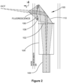
Figure 2 is a schematic side view of the optical element shown inFigure 1 ; -
Figure 3 is a schematic top view of the optical element shown inFigure 1 ; -
Figures 4 (a) to (d) illustrate optical components in accordance with embodiments of the present invention; -
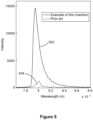
Figure 5 is a graph showing measurement data obtained using a device in accordance with an embodiment of the present invention; -
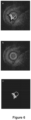
Figure 6 (a)-(c) are images obtained using a device in accordance with an embodiment of the present invention; -
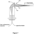
Figure 7 illustrates an optical element in accordance with an example not encompassed by the wording of the claims; and -
Figure 8 is a flow chart illustrating a method in accordance with an embodiment of the present invention. - Referring initially to
Figures 1 to 3 , anoptical element 100 in accordance with an embodiment of the present invention is now described. Theoptical element 100 has afirst surface 102 for emitting and/or receiving electromagnetic radiation and which is optically coupled to an end-portion of anoptical fibre 104. In this embodiment theoptical fibre 104 is a no-core fibre which is spliced onto a double-cladoptical fibre 105. Theoptical element 100 is directly formed on the end-portion of theoptical fibre 104. - The
optical element 100 also has asecond surface 106 positioned for emitting and/or receiving electromagnetic radiation in a direction transversal to an axis of theoptical fibre 104. In this embodiment thesecond surface 106 is positioned for emitting and receiving electromagnetic radiation in a direction that is substantially perpendicular to the axis of theoptical fibre 104. - The
optical element 100 has a first focal length for electromagnetic radiation emitted and/or received by an inner portion of thesecond surface 106 and a second focal length for electromagnetic radiation emitted and/or received by an outer portion of thesecond surface 106. The first and second focal lengths are different focal lengths. - The inner portion of the
second surface 106 has a larger focal length and larger depth of field, which is advantageous for OCT imaging. The outer portion of thesecond surface 106 has a shorter focal length than the inner portion, but a larger numerical aperture allowing efficient collection of fluorescence radiation. Other combinations of focal lengths may be chosen. The choice of focal lengths may be selected to optimise optical performance of theoptical element 100 with respect to one or more optical technologies. Optical technologies include OCT, fluorescence, confocal microscopy, multiphoton microscopy, diffuse optical tomography, total internal reflection fluorescence microscopy, phase contrast microscopy, stimulated emission depletion microscopy, near-field scanning optical microscopy, differential interference contrast microscopy, second harmonic imaging microscopy, reflectance spectroscopy, Raman spectroscopy and optical coherence elastography. - The inner portion of the
second surface 106 is arranged to mainly direct received radiation (such as OCT signals) into an inner portion of the no-core fibre 104 and subsequently into a core region of theoptical fibre 105. The outer portion of the second surface 106 (associated with a larger numerical aperture) is arranged to mainly direct radiation (such as fluorescence radiation) into an outer portion of the no-core fibre 104 and subsequently into an inner cladding region of theoptical fibre 105. For fluorescence measurements for example, achievable signal-to-noise ratio is related to the numerical aperture of the collection cone. In this embodiment the outer portion of thesecond surface 106 has a numerical aperture greater than 0.4 resulting in a relatively high signal to noise ratio and corresponding high sensitivity. - The
optical element 100 is shaped such that light is directed from the transversal direction to a direction along the axis of theoptical fibre 104 using total internal reflection atsurface 110. In a variation of the described embodiment thesurface 110 may be replaced with a surface having a reflective or dichroic coating and thesurface 110 may be a freeform surface. - The
optical element 100 may be used for "side-viewing" endoscopic or intravascular probes, which are usually used within a transparent catheter sheath in order to protect tissue within which the probe is being moved during examination and also to prevent contamination of the probe. Such a transparent sheath corresponds optically to a negative cylindrical lens and causes astigmatism. Thesurface 110 may be shaped to optically correct the astigmatism. Further, theoptical element 100 may comprise a grating structure to correct chromatic aberration or achieve colour separation. - The
optical element 100 may have any suitable dimension. For example, thesecond surface 106 of the optical 100 may have an outer diameter in the range of 1mm to 0.1mm or even less. Thefirst surface 102 may have an outer diameter that coincides with an outer diameter of theoptical fibre 104 to which theoptical element 100 is coupled. For example, thefirst surface 102 may have an outer diameter of less than 1.5mm to 0.1mm or less. - The
optical element 100 may be structured such that the inner portion of thesecond surface 106 has a focal length in the range 0.5mm to 2mm at a wavelength range of 500 nm to 1900nm. The inner portion may have any suitable shape, but in one embodiment is circular having an outer diameter that is 10% - 90% smaller than an outer diameter of the outer portion of thesecond surface 106. - Further, the
optical element 100 may be structured such that the outer portion of thesecond surface 106 has a focal length of 0.1mm - 0.5mm at a wavelength range of 400nm to 1000nm. The outer portion of theoptical element 100 may have a numerical aperture greater than a numerical aperture of the inner portion by at least 0.1 to 0.8 or more. The outer portion may have any suitable shape, but is in this embodiment ring-shaped. - In one embodiment the
optical element 100 is arranged to reduce or avoid cross-talk between radiation received by the outer and inner portions of theoptical element 100. Such cross-talk, which may have a detrimental effect on measurement results or image quality, can for example be reduced by optimising the ratio between the diameter of the aperture of the outer portion and the diameter of the aperture of the inner portion of thesecond surface 106 or optimising the tilt angle of the inner and outer portions. In one example this ratio of tilt angle is 3:1 and the tilt angle is chosen such that radiation having a selected wavelength range will not undergo total internal reflection at reflective surfaces of theoptical element 100. - Further, an optical isolation element (not shown) may be used which selectively absorbs or otherwise filters radiation over specific wavelength ranges. The optical isolation element may for example be positioned at surfaces at which received electromagnetic radiation is reflected. Additionally or alternatively, a coating may be applied to an outer surface of the
fibre optical fibre optical fibre optical fibre - The
optical element 100 may be integrally formed from an optically transmissive material using a 3D printing process, which will be described further below in more detail. - Referring now to
Figure 4 (a) to (d) , examples of lens surfaces that may form thesecond surface 106 or theoptical element 100 are now described. In each example the lens surfaces are shaped such that an inner portion has a larger focal length, a larger depth of field and a smaller numerical aperture whereas an outer portion has a shorter focal length, a larger numerical aperture and a shorter depth of field. -
Figure 4(a) is a schematic cross-sectional representation of aconventional lens 402 shown to illustrate a possible shape of thesurface 403, which could form thesecond surface 106 of theoptical element 100 illustrated above with reference toFigures 1 to 3 . Thesurface 403 has a non-uniform curvature resulting in an inner portion having a larger focal length than an outer portion. -
Figure 4 (b) is a schematic cross-sectional representation of aFresnel lens 404 shown to illustrate a possible shape of thesurface 405, which also could form thesecond surface 106 of theoptical element 100 illustrated above with reference toFigures 1 to 3 . Thesurface 405 has an inner Fresnel zone resulting in a larger focal length and an outer Fresnel zone resulting in a shorter focal length. -
Figure 4 (c) is a schematic cross-sectional representation of aMetalens 406 having asurface 407, which also could also form thesecond surface 106 of theoptical element 100 illustrated above with reference toFigures 1 to 3 . Thesurface 407 is structured such that an inner portion has a larger focal length than an outer portion. - As a further alternative the
surface 407 may for example be a surface of a diffractive optical element (DOE) having diffractive properties that result in a larger focal length in an inner portion than in an outer portion. -
Figure 4 (d) is a schematic cross-sectional representation of thesecond surface 106 that comprises more than one type of lens. In this example, theouter portion 108 is a total internal reflection (TIR) lens and theinner portion 109 is a refractive lens. Each TIR facet of the TIR lens uses TIR to redirect light into theoptical element 100, as shown in the zoomed inset ofFigure 4 (d) . The light that passes through the outer portion of the lens may additionally be refracted at a surface of the lens. Using a combination of refraction and TIR in a lens has the advantage of enabling highly compact optical designs with large numerical aperture. - As a further example, the inner portion of the
second surface 106 can be a diffractive optical element and the outer portion of thesecond surface 106 can be a refractive lens. -
Figure 5 is a graph illustrating intensity offluorescence radiation 502 detected with the device including the optical element in accordance with the present invention compared with the intensity offluorescence radiation 504 detected using a prior art device.Figure 5 illustrates that the device including the optical element in accordance with the present invention is capable of higher sensitivity fluorescence measurements than possible using a prior art device, which is a result of the high numerical aperture associated with the outer portion of the second surface of the optical element in accordance with the embodiments of the present invention. In contrast, depth of field of the inner portion of the second surface is advantageous for OCT imaging. - It will be appreciated by a person skilled in the art that the optical element in accordance with embodiments of the present invention may be used for various applications and is not limited to the use for OCT and fluorescence imaging. For example, the optical element may also be used for auto-fluorescence imaging, auto-fluorescence sensing, fluorescence imaging using contrast agents, fluorescence sensing using contrast agents, confocal microscopy, multiphoton microscopy, diffuse optical tomography, total internal reflection fluorescence microscopy, phase contrast microscopy, stimulated emission depletion microscopy, near-field scanning optical microscopy, differential interference contrast microscopy, second harmonic imaging microscopy, reflectance spectroscopy, Raman spectroscopy and optical coherence elastography.
-
Figure 6 (a) is an exemplary merged OCT and auto-fluorescence image obtained using a device including an optical element in accordance with an embodiment of the present invention.Figure 6 (b) and (c) show the corresponding OCT image and auto-fluorescence image, respectively. The images show an atherosclerotic plaque obtained with an example of the invention. A plaque at 6-9 o'clock was confirmed by a high intensity of the detected fluorescence radiation, as shown inFigure 6 (a) and (c) . In this embodiment the inner portion of the optical element was designed to optimally transmit radiation with a bandwidth of more than 50 nm and the outer portion of the optical element can be designed to optimally transmit radiation with a bandwidth of more than 20 nm. -
Figure 7 illustrates anoptical element 700 in accordance with an example not encompassed by the wording of the claims. In this example aninner portion 702 of thesecond surface 704 of theoptical element 700 is a surface of a diffractive optical element (DOE) and has been optimised for chromatic confocal imaging and allows different wavelength range to be focused at different locations. InFigure 7 , the different wavelength ranges are represented by different shades of grey. Thus, depth-resolved confocal signals can be detected using a spectrometer (not shown) which separates signals from various wavelengths onto different pixels of a detector (not shown). Anouter portion 706 of thesecond surface 704 may also be a surface of a DOE or may, for example, be a Fresnel zone having a shorter focal length and a larger numerical aperture than theinner portion 702. - A person skilled in the art will appreciate that the optical element in accordance with embodiments of the present invention may be used to examine biological tissue and may be used in-vivo and ex-vivo. For example, the optical element may be used for intravascular imaging, diagnosis and treatment, and can also be used for other endoscopic applications, for example for examination of digestive, respiratory, urinary and reproductive systems and ears, and for diagnosing and treating cancers and other diseases. Alternatively, the optical element may be used for examining any type of object including for example pipes, tanks or other structures.
- Further, the optical element in accordance with embodiments of the present invention and at least a portion of optical fibre that is optically coupled to the optical element may be positioned within a metal tube or a needle that has an inlet that is transmissive for at least electromagnetic radiation.
- Further, the optical element may not necessarily be used for simultaneous measurements associated with different measurement or imaging techniques. The optical element may also be used to acquire multiple measurements or images using a single technique, with the inner and outer portions of the optical element optimised for different acquisition parameters. For example, inner and outer portions of the second surface of the optical element may be optimised for acquiring fluorescence radiation at different depths within an object or within tissue of interest.
- A
method 800 of forming an optical device in accordance with an embodiment of the present invention is now described. The optical device comprises an optical fibre on which in this embodiment an optical element is formed. The optical element may for example be theoptical element 100 described above. - The
method 800 comprises theinitial step 802 of providing a design for the optical element. Step 802 comprises designing the optical element, for example by using the optical design software "Zemax", and exporting a resulting design in computer aided design (CAD) file format. Further, the design may be further refined using the software "Solidworks" (Dassault Systèmes, France). - The
method 800 further comprises step 804 of providing an optical fibre and positioning an end portion of the optical fibre relative to a multi-photon 3D printing system. Step 804 may comprise providing a length of no-core fibre or step-index fibre spliced onto a double clad or single mode optical fibre. - Further, the
method 800 comprisesstep 806 of instructing a multi-photon lithography system to 3D print the optical element in accordance with the provided design. - The multi-photon lithography system allows printing of the optical element directly onto an end of the optical fibre. After mounting the optical fibre using a suitable fibre holder in the multi-photon lithography system, the system is aligned relative to the end of the optical fibre, which can be facilitated by directing light into an opposite end of the fibre. It is then possible to identify the other end of the optical fibre using a CCD camera. The optical element is then printed onto the end of the optical fibre whereby the optical element is integrally formed using a suitable photosensitive material such as "Nanoscribe IP-S".
Claims (13)
- An optical element (100) comprising:a first surface (102) for emitting and/or receiving electromagnetic radiation, the first surface (102) being arranged for optically coupling to, or being optically coupled to, a portion of an optical fibre (104), the optical fibre (104) having an axis; anda second surface (106) positioned for emitting and/or receiving electromagnetic radiation in a direction transversal to the axis of the optical fibre (104);wherein the optical element (100) has a first focal length for electromagnetic radiation emitted and/or received by an inner portion of the second surface (106) and a second focal length for electromagnetic radiation emitted and/or received by an outer portion of the second surface (106), the first and second focal lengths being different focal lengths;wherein the inner portion and the outer portion of the second surface (106) are optimised for use of the optical element (100) to acquire measurements at different acquisition parameters using one or more optical technologies; andcharacterised in that the first focal length is larger than the second focal length, and in that a depth of field associated with the inner portion of the second surface (106) is larger than a depth of field associated with the outer portion of the second surface (106).
- The optical element (100) of claim 1, characterised in that the inner portion and the outer portion of the second surface (106) are optimised for use of the optical element (100) to acquire measurements at different acquisition parameters using at least two different optical technologies.
- The optical element (100) of claim 1 or 2, characterised in that the optical element (100) is integrally formed.
- The optical element (100) of any one of the preceding claims, characterised in that the outer portion of the second surface (106) entirely surrounds the inner portion of the second surface (106).
- The optical element (100) of any one of the preceding claims, characterised in that the optical element (100) is arranged such that at least a portion or the majority of electromagnetic radiation received within the inner portion of the second surface (106) is directed into a central region, such as a core region, of the optical fibre (104) and at least a portion or the majority of electromagnetic radiation received within the outer portion of the second surface (106) is directed into a region of the optical fibre (104) surrounding the central region, such as a cladding or inner cladding region of the optical fibre.
- The optical element (100) of any one of the preceding claims, characterised in that the outer portion has a focal length that result in numerical aperture greater than the numerical aperture of the inner portion by at least 0.1, 0.2, 0.3, 0.4, 0.5, 0.6, 0.7 or 0.8.
- The optical element (100) of any one of the preceding claims, characterised in that the optical element has a diameter less than 1mm, 0.5mm, 0.2mm or 0.1mm.
- The optical element (100) of any one of the preceding claims, comprising at least one reflective surface (110), the reflective surface (110) having a reflective coating or a dichroic coating or being positioned for total internal reflection of electromagnetic radiation.
- The optical element (100) of claim 8, characterised in that the reflective surface (110) is arranged to direct electromagnetic radiation between the direction along the axis of the optical fibre (104) and the direction transversal to the axis of the optical fibre (104).
- The optical element (100) of any one of the preceding claims, characterised in that the optical element (100) is formed directly on an end portion of the optical fibre (104).
- An optical device comprising the optical element (100) in accordance with any one of the preceding claims, the optical device further comprising an optical fibre coupled to the optical element (100).
- The optical device of claim 11, characterised in that the optical fibre is a no core optical fibre.
- A method (800) of forming the optical device in accordance with claim 11 or 12, the method comprising the steps of:providing a design for the optical element (100);providing an optical fibre and positioning an end portion of the optical fibre relative to a multi-photon lithography system;
andinstructing the multi-photon lithography system to 3D print the optical element (100) in accordance with the provided design.
Applications Claiming Priority (2)
| Application Number | Priority Date | Filing Date | Title |
|---|---|---|---|
| AU2020902567A AU2020902567A0 (en) | 2020-07-23 | An optical element | |
| PCT/AU2021/050797 WO2022016230A1 (en) | 2020-07-23 | 2021-07-23 | An optical element |
Publications (4)
| Publication Number | Publication Date |
|---|---|
| EP4185902A1 EP4185902A1 (en) | 2023-05-31 |
| EP4185902A4 EP4185902A4 (en) | 2023-12-20 |
| EP4185902B1 true EP4185902B1 (en) | 2025-06-18 |
| EP4185902C0 EP4185902C0 (en) | 2025-06-18 |
Family
ID=79729565
Family Applications (1)
| Application Number | Title | Priority Date | Filing Date |
|---|---|---|---|
| EP21846362.8A Active EP4185902B1 (en) | 2020-07-23 | 2021-07-23 | An optical element |
Country Status (7)
| Country | Link |
|---|---|
| US (1) | US12607836B2 (en) |
| EP (1) | EP4185902B1 (en) |
| JP (1) | JP7761906B2 (en) |
| CN (1) | CN116157667B (en) |
| AU (1) | AU2021312548A1 (en) |
| ES (1) | ES3037203T3 (en) |
| WO (1) | WO2022016230A1 (en) |
Families Citing this family (2)
| Publication number | Priority date | Publication date | Assignee | Title |
|---|---|---|---|---|
| CN118078192B (en) * | 2024-02-26 | 2025-11-28 | 上海交通大学 | Multi-modality imaging catheter and multi-modality imaging system |
| WO2026083684A1 (en) * | 2024-10-17 | 2026-04-23 | キヤノン株式会社 | Optical system and imaging device |
Family Cites Families (8)
| Publication number | Priority date | Publication date | Assignee | Title |
|---|---|---|---|---|
| JP4464519B2 (en) | 2000-03-21 | 2010-05-19 | オリンパス株式会社 | Optical imaging device |
| EP2096990A1 (en) | 2006-12-22 | 2009-09-09 | Koninklijke Philips Electronics N.V. | An imaging system with two imaging modalities |
| KR20130004326A (en) | 2010-03-05 | 2013-01-09 | 더 제너럴 하스피탈 코포레이션 | Systems, methods and computer-accessible medium which provide microscopic images of at least one anatomical structure at a particular resolution |
| WO2011149972A2 (en) * | 2010-05-25 | 2011-12-01 | The General Hospital Corporation | Systems, devices, methods, apparatus and computer-accessible media for providing optical imaging of structures and compositions |
| US9605942B2 (en) | 2013-07-31 | 2017-03-28 | Corning Incorporated | OCT probes and OCT optical probe component for use therein |
| US11519712B2 (en) | 2016-07-05 | 2022-12-06 | The General Hospital Corporation | Systems and methods for an actively controlled optical imaging device |
| DE102016221464A1 (en) | 2016-11-02 | 2018-05-03 | Karlsruher Institut für Technologie | Method of making an optical system and optical system |
| US10413167B2 (en) | 2017-05-30 | 2019-09-17 | Synaptive Medical (Barbados) Inc. | Micro-optical surgical probes and micro-optical probe tips and methods of manufacture therefor |
-
2021
- 2021-07-23 JP JP2023504103A patent/JP7761906B2/en active Active
- 2021-07-23 EP EP21846362.8A patent/EP4185902B1/en active Active
- 2021-07-23 CN CN202180059919.6A patent/CN116157667B/en active Active
- 2021-07-23 AU AU2021312548A patent/AU2021312548A1/en active Pending
- 2021-07-23 US US18/006,373 patent/US12607836B2/en active Active
- 2021-07-23 ES ES21846362T patent/ES3037203T3/en active Active
- 2021-07-23 WO PCT/AU2021/050797 patent/WO2022016230A1/en not_active Ceased
Also Published As
| Publication number | Publication date |
|---|---|
| ES3037203T3 (en) | 2025-09-30 |
| WO2022016230A1 (en) | 2022-01-27 |
| EP4185902A4 (en) | 2023-12-20 |
| CN116157667A (en) | 2023-05-23 |
| EP4185902A1 (en) | 2023-05-31 |
| AU2021312548A1 (en) | 2023-02-23 |
| US20230341668A1 (en) | 2023-10-26 |
| EP4185902C0 (en) | 2025-06-18 |
| CN116157667B (en) | 2026-01-02 |
| JP2023538224A (en) | 2023-09-07 |
| US12607836B2 (en) | 2026-04-21 |
| JP7761906B2 (en) | 2025-10-29 |
Similar Documents
| Publication | Publication Date | Title |
|---|---|---|
| US8184367B2 (en) | Dynamically focused optical instrument | |
| EP3010389B1 (en) | Omni-directional viewing apparatus and method | |
| JP6726326B2 (en) | Optical probe with astigmatism correction | |
| US8705184B2 (en) | Multi-path, multi-magnification, non-confocal fluorescence emission endoscopy apparatus and methods | |
| US8384907B2 (en) | Method and apparatus for optical imaging via spectral encoding | |
| JP5305035B2 (en) | High spatial resolution and high sensitivity compact optical head for fiber confocal fluorescence imaging | |
| US20130324858A1 (en) | Multi-path, multi-magnification, non-confocal fluorescence emission endoscopy apparatus and methods | |
| WO2010027125A1 (en) | Spectrally encoded cars endoscope | |
| CN111474694B (en) | A micro endoscope with a large field of view | |
| US20190223700A1 (en) | Optical probes with optical-correction components | |
| WO2017049085A1 (en) | Apparatus and methods for mirror tunnel imaging device and for providing pseudo-bessel beams in a miniaturized optical system for imaging | |
| US12607836B2 (en) | Optical element | |
| WO2013170145A1 (en) | Dual mode microendoscope apparatus, method and applications | |
| CN112493969B (en) | Fine spectrum coding parallel imaging probe based on virtual image phased array | |
| CN109564327B (en) | Ring beam coupling system | |
| CN111819417A (en) | Common Optical Path Waveguides for Stabilized Optical Coherence Tomography Imaging | |
| CN118078192B (en) | Multi-modality imaging catheter and multi-modality imaging system | |
| HK40087777B (en) | An optical element | |
| HK40087777A (en) | An optical element | |
| US20100288912A1 (en) | optical probe | |
| EP3773163B1 (en) | Fiber endoscope | |
| CN119472008A (en) | A miniature endoscope lens suitable for label-free quantitative phase microscopy | |
| CN117084628A (en) | Multifocal multimodal imaging catheter |
Legal Events
| Date | Code | Title | Description |
|---|---|---|---|
| STAA | Information on the status of an ep patent application or granted ep patent |
Free format text: STATUS: THE INTERNATIONAL PUBLICATION HAS BEEN MADE |
|
| PUAI | Public reference made under article 153(3) epc to a published international application that has entered the european phase |
Free format text: ORIGINAL CODE: 0009012 |
|
| STAA | Information on the status of an ep patent application or granted ep patent |
Free format text: STATUS: REQUEST FOR EXAMINATION WAS MADE |
|
| 17P | Request for examination filed |
Effective date: 20230216 |
|
| AK | Designated contracting states |
Kind code of ref document: A1 Designated state(s): AL AT BE BG CH CY CZ DE DK EE ES FI FR GB GR HR HU IE IS IT LI LT LU LV MC MK MT NL NO PL PT RO RS SE SI SK SM TR |
|
| REG | Reference to a national code |
Ref country code: HK Ref legal event code: DE Ref document number: 40087777 Country of ref document: HK |
|
| DAV | Request for validation of the european patent (deleted) | ||
| DAX | Request for extension of the european patent (deleted) | ||
| REG | Reference to a national code |
Ref country code: DE Ipc: G01B0009020150 Ref legal event code: R079 Ref document number: 602021032584 Country of ref document: DE Free format text: PREVIOUS MAIN CLASS: G02B0003000000 |
|
| A4 | Supplementary search report drawn up and despatched |
Effective date: 20231117 |
|
| RIC1 | Information provided on ipc code assigned before grant |
Ipc: G01B 9/02091 20220101ALI20231113BHEP Ipc: A61B 5/00 20060101ALI20231113BHEP Ipc: A61B 1/00 20060101ALI20231113BHEP Ipc: G02B 23/24 20060101ALI20231113BHEP Ipc: G02B 17/08 20060101ALI20231113BHEP Ipc: G02B 6/26 20060101ALI20231113BHEP Ipc: G02B 3/08 20060101ALI20231113BHEP Ipc: G01B 11/06 20060101ALI20231113BHEP Ipc: G02B 21/00 20060101ALI20231113BHEP Ipc: G01B 9/02 20220101ALI20231113BHEP Ipc: G01N 21/00 20060101ALI20231113BHEP Ipc: G02B 3/00 20060101ALI20231113BHEP Ipc: G01B 9/02015 20220101AFI20231113BHEP |
|
| GRAP | Despatch of communication of intention to grant a patent |
Free format text: ORIGINAL CODE: EPIDOSNIGR1 |
|
| STAA | Information on the status of an ep patent application or granted ep patent |
Free format text: STATUS: GRANT OF PATENT IS INTENDED |
|
| RIC1 | Information provided on ipc code assigned before grant |
Ipc: G01B 9/02091 20220101ALI20250304BHEP Ipc: A61B 5/00 20060101ALI20250304BHEP Ipc: A61B 1/00 20060101ALI20250304BHEP Ipc: G02B 23/24 20060101ALI20250304BHEP Ipc: G02B 17/08 20060101ALI20250304BHEP Ipc: G02B 6/26 20060101ALI20250304BHEP Ipc: G02B 3/08 20060101ALI20250304BHEP Ipc: G01B 11/06 20060101ALI20250304BHEP Ipc: G02B 21/00 20060101ALI20250304BHEP Ipc: G01B 9/02 20220101ALI20250304BHEP Ipc: G01N 21/00 20060101ALI20250304BHEP Ipc: G02B 3/00 20060101ALI20250304BHEP Ipc: G01B 9/02015 20220101AFI20250304BHEP |
|
| INTG | Intention to grant announced |
Effective date: 20250318 |
|
| GRAS | Grant fee paid |
Free format text: ORIGINAL CODE: EPIDOSNIGR3 |
|
| GRAA | (expected) grant |
Free format text: ORIGINAL CODE: 0009210 |
|
| STAA | Information on the status of an ep patent application or granted ep patent |
Free format text: STATUS: THE PATENT HAS BEEN GRANTED |
|
| AK | Designated contracting states |
Kind code of ref document: B1 Designated state(s): AL AT BE BG CH CY CZ DE DK EE ES FI FR GB GR HR HU IE IS IT LI LT LU LV MC MK MT NL NO PL PT RO RS SE SI SK SM TR |
|
| REG | Reference to a national code |
Ref country code: GB Ref legal event code: FG4D |
|
| REG | Reference to a national code |
Ref country code: CH Ref legal event code: EP |
|
| PGFP | Annual fee paid to national office [announced via postgrant information from national office to epo] |
Ref country code: GB Payment date: 20250624 Year of fee payment: 5 |
|
| REG | Reference to a national code |
Ref country code: DE Ref legal event code: R096 Ref document number: 602021032584 Country of ref document: DE |
|
| REG | Reference to a national code |
Ref country code: CH Ref legal event code: EP |
|
| REG | Reference to a national code |
Ref country code: IE Ref legal event code: FG4D |
|
| U01 | Request for unitary effect filed |
Effective date: 20250630 |
|
| U07 | Unitary effect registered |
Designated state(s): AT BE BG DE DK EE FI FR IT LT LU LV MT NL PT RO SE SI Effective date: 20250707 |
|
| U20 | Renewal fee for the european patent with unitary effect paid |
Year of fee payment: 5 Effective date: 20250703 |
|
| REG | Reference to a national code |
Ref country code: ES Ref legal event code: FG2A Ref document number: 3037203 Country of ref document: ES Kind code of ref document: T3 Effective date: 20250930 |
|
| PGFP | Annual fee paid to national office [announced via postgrant information from national office to epo] |
Ref country code: ES Payment date: 20250820 Year of fee payment: 5 |
|
| PG25 | Lapsed in a contracting state [announced via postgrant information from national office to epo] |
Ref country code: GR Free format text: LAPSE BECAUSE OF FAILURE TO SUBMIT A TRANSLATION OF THE DESCRIPTION OR TO PAY THE FEE WITHIN THE PRESCRIBED TIME-LIMIT Effective date: 20250919 Ref country code: NO Free format text: LAPSE BECAUSE OF FAILURE TO SUBMIT A TRANSLATION OF THE DESCRIPTION OR TO PAY THE FEE WITHIN THE PRESCRIBED TIME-LIMIT Effective date: 20250918 |
|
| PG25 | Lapsed in a contracting state [announced via postgrant information from national office to epo] |
Ref country code: HR Free format text: LAPSE BECAUSE OF FAILURE TO SUBMIT A TRANSLATION OF THE DESCRIPTION OR TO PAY THE FEE WITHIN THE PRESCRIBED TIME-LIMIT Effective date: 20250618 |
|
| PGFP | Annual fee paid to national office [announced via postgrant information from national office to epo] |
Ref country code: CH Payment date: 20250801 Year of fee payment: 5 |
|
| PG25 | Lapsed in a contracting state [announced via postgrant information from national office to epo] |
Ref country code: RS Free format text: LAPSE BECAUSE OF FAILURE TO SUBMIT A TRANSLATION OF THE DESCRIPTION OR TO PAY THE FEE WITHIN THE PRESCRIBED TIME-LIMIT Effective date: 20250918 |
|
| PG25 | Lapsed in a contracting state [announced via postgrant information from national office to epo] |
Ref country code: IS Free format text: LAPSE BECAUSE OF FAILURE TO SUBMIT A TRANSLATION OF THE DESCRIPTION OR TO PAY THE FEE WITHIN THE PRESCRIBED TIME-LIMIT Effective date: 20251018 |
|
| PG25 | Lapsed in a contracting state [announced via postgrant information from national office to epo] |
Ref country code: SM Free format text: LAPSE BECAUSE OF FAILURE TO SUBMIT A TRANSLATION OF THE DESCRIPTION OR TO PAY THE FEE WITHIN THE PRESCRIBED TIME-LIMIT Effective date: 20250618 |
|
| PG25 | Lapsed in a contracting state [announced via postgrant information from national office to epo] |
Ref country code: CZ Free format text: LAPSE BECAUSE OF FAILURE TO SUBMIT A TRANSLATION OF THE DESCRIPTION OR TO PAY THE FEE WITHIN THE PRESCRIBED TIME-LIMIT Effective date: 20250618 |
|
| PG25 | Lapsed in a contracting state [announced via postgrant information from national office to epo] |
Ref country code: PL Free format text: LAPSE BECAUSE OF FAILURE TO SUBMIT A TRANSLATION OF THE DESCRIPTION OR TO PAY THE FEE WITHIN THE PRESCRIBED TIME-LIMIT Effective date: 20250618 |
|
| PG25 | Lapsed in a contracting state [announced via postgrant information from national office to epo] |
Ref country code: SK Free format text: LAPSE BECAUSE OF FAILURE TO SUBMIT A TRANSLATION OF THE DESCRIPTION OR TO PAY THE FEE WITHIN THE PRESCRIBED TIME-LIMIT Effective date: 20250618 |
|
| PG25 | Lapsed in a contracting state [announced via postgrant information from national office to epo] |
Ref country code: MC Free format text: LAPSE BECAUSE OF FAILURE TO SUBMIT A TRANSLATION OF THE DESCRIPTION OR TO PAY THE FEE WITHIN THE PRESCRIBED TIME-LIMIT Effective date: 20250618 |
|
| PLBE | No opposition filed within time limit |
Free format text: ORIGINAL CODE: 0009261 |
|
| STAA | Information on the status of an ep patent application or granted ep patent |
Free format text: STATUS: NO OPPOSITION FILED WITHIN TIME LIMIT |
|
| REG | Reference to a national code |
Ref country code: CH Ref legal event code: L10 Free format text: ST27 STATUS EVENT CODE: U-0-0-L10-L00 (AS PROVIDED BY THE NATIONAL OFFICE) Effective date: 20260430 |