EP4185075A1 - Bidirectional communication and control system via powerline for emergency lighting - Google Patents
Bidirectional communication and control system via powerline for emergency lighting Download PDFInfo
- Publication number
- EP4185075A1 EP4185075A1 EP22206360.4A EP22206360A EP4185075A1 EP 4185075 A1 EP4185075 A1 EP 4185075A1 EP 22206360 A EP22206360 A EP 22206360A EP 4185075 A1 EP4185075 A1 EP 4185075A1
- Authority
- EP
- European Patent Office
- Prior art keywords
- cps
- previous
- elms
- unit
- communication
- Prior art date
- Legal status (The legal status is an assumption and is not a legal conclusion. Google has not performed a legal analysis and makes no representation as to the accuracy of the status listed.)
- Pending
Links
Images


Classifications
-
- H—ELECTRICITY
- H05—ELECTRIC TECHNIQUES NOT OTHERWISE PROVIDED FOR
- H05B—ELECTRIC HEATING; ELECTRIC LIGHT SOURCES NOT OTHERWISE PROVIDED FOR; CIRCUIT ARRANGEMENTS FOR ELECTRIC LIGHT SOURCES, IN GENERAL
- H05B47/00—Circuit arrangements for operating light sources in general, i.e. where the type of light source is not relevant
- H05B47/10—Controlling the light source
- H05B47/175—Controlling the light source by remote control
- H05B47/185—Controlling the light source by remote control via power line carrier transmission
Definitions
- the present invention discloses a bidirectional communication and control system via powerline for emergency lighting using a powerline and further comprising a central power system CPS connected to the mains, a number of emergency lamp modules ELMs and/or sensor modules SMs.
- the ELMs are connected to at least one luminaire or one string of luminaires, such as LEDs.
- the corresponding ELMs and SMs are connected to each other by powerline and to the central power system CPS, wherein such powerline communication PLC is used for bidirectional communication between CPS and each ELM/SM.
- the purpose for using such PLC is to remove double wiring for power and data communication and keep only the power cable or powerline to transmit the data along with power between devices.
- bidirectional communication and control system for emergency lighting such that true bidirectional communication between CPS and ELM/SM is possible for all types of network topologies and which is possible for both Vac or Vdc powerlines,at least in the ranges of 175 Vac to 275 Vac or 150 Vdc to 290 Vdc.
- one particular architecture of the bidirectional communication and control system for emergency lighting should be provided which is also usable for all types of network topologies.
- CENB there is a single solution to cover CENB, namely, CENELEC B frequency band and FCC-2, which means upper FCC frequency band.
- the CENELEC B frequency band has frequencies of about 95kHz to 125kHz and the upper FCC frequency band has frequencies in the range of 150kHz to 500kHz.
- such bidirectional communication and control system for emergency lighting described above is improved to solve those objects in that there is at least one communication unit CU connected between CPS and ELMs/SMs to coordinate communication between CPS and ELMs/SMs and to communicate with CPS and ELMs/SMs, which CU comprises at least a filter unit, a PLC modem, a coupling transformer, as well as transmitter and receiver filter units.
- the corresponding communication unit may be directly assigned to the CPS or may even be part of same.
- the filter unit is used to attenuate frequencies, in particular the carrier frequencies. For example it can be realized as an impedance upper and EMI filter unit.
- the corresponding PLC modem transmits, receives, encodes and decodes data, and the coupling transformer couples transmitter data and decouples receiver data.
- Corresponding transmitter and/or receiver filter units are used to filter transmitter data to be coupled with powerline via coupling transformer and/or the receiver filter unit filters receiver signals except the carrier frequency. In particular the transmitter filter unit is optional.
- the CU is connected to a number of strings in parallel, wherein each string comprises a number of ELMs and/or SMs. Each ELM is then connected to a corresponding luminaire or string of luminaires.
- the CU can be connected to a control and switchover unit of the CPS.
- Such control and switchover unit CSU is in particular configured to switch between single or three phase mains and a second power source, in particular a battery system.
- the corresponding communication unit of the CPS acts as a coordinator or master for communication between CPS and ELMs/SMs. It will communicate with a CPS system controller and will relay info and instructions between CPS and ELMs/SMs.
- each ELM and/or SM may further comprise a controller or and ELM driver or SM circuitry.
- the ELM driver may comprise a buck converter circuitry, a module controller and at least one sensing circuitry.
- the buck converter is generally used to convert a power level for any connected string of luminaires.
- the corresponding module controller is used to control the buck converter as well as communicate with a communication unit to route corresponding instructions.
- voltage, current and temperature may be detected by the sensing circuitry for prognostics and diagnostics of the string of luminaires and any other ELM circuitry.
- the corresponding SM will also comprise a controller to communicate sensor data with the communication unit and may have at least one sensor.
- the communication unit may have further parts, such as for example an isolated power supply unit PSU, PLC Modem, a transmitter line driver, TX/RX Filters and coupling transformer wherein the isolated PSU is to provide power to corresponding low voltage circuits.
- the Tx filter and transmitter line driver are connected to PLC modem and are in particular used to amplify and filter TX data to be coupled with power line via coupling transformer.
- Corresponding CUs can also be part of each ELM/SM and can be connected in parallel with corresponding transmitter and receiver units of the CPS.
- the coupling transformer may be used to couple Tx data and to decouple Rx data.
- the Tx filter is optional.
- the CPS may further comprise a line driver protection unit connected to the line drivers of the CUs connected to ELMs/SMs and/or comprise a PLC module.
- the line driver protection module takes care of thermal and other electrical overstress protection logic for all TX line drivers.
- a corresponding ELM may be assigned to a string of luminaires but also to a luminaire or part of same.
- the corresponding SM is part of such string of luminaires and may be integrated in an ELM or can be a stand alone module.
- a network stabilizer connected to at least one string of ELMs/SMs and it is further possible according to the present application that a communication between CPS and ELMs/SMs is a parallel communication between CU of CPS and CUs of ELMs/SMs.
- each SM may be a standalone module or may be integrated in a corresponding ELM.
- network topologies are for example, bus, star, daisy chain or either bridge topology.
- Fig. 1 illustrates one kind of architecture of corresponding bidirectional communication and control system 1.
- This comprises a central power system CPS 2 with connection to mains 3, a control and switchover unit CSU 14, a second power source 15 and a communication unit CU of the CPS 2, see reference numeral 8.
- the mains may be single or three phase AC and the second power source 15 may be a battery.
- the controller and switchover unit CSU 14 changes the powerlines between primary, see mains, and secondary power source based on requirements.
- the CU 8 acts as a coordinator/master for communication between the CPS and a plurality of emergency lighting lamp modules ELMs 4 and/or sensor modules SMs 6.
- the corresponding ELMs, SMs are arranged in parallel with respect to a corresponding powerline communication PLC 7 in form of a powerline 31.
- Each of the ELMs may be connected to a string of luminaire or may also be integrated in a particular luminaire.
- Fig. 2 is a particular embodiment of the present application, according to which a number of CUs 8 are arranged in parallel and are connected to the CPS 2.
- the CPS 2 comprises a coordinator with a transmitter unit 26 and a receiver unit 27, which are used for transmitter paralleling and control and receiver summing.
- Fig. 2 there are four corresponding communication units 8, each connected to circuit in and circuit out, see also Fig. 6 , wherein there is this particular transmitter paralleling and control, see reference numeral 26, 32 according to which, it is possible to send corresponding signal from this coordinator to all four communication units.
- receiver summing see reference numeral 27, 33, which receives data from the ELMs/SMs and will coordinate same by corresponding firmware so that one data will be available on powerline, wherein the receiver summing module will physically add signals available from all other receiver modules of the communication units 8, to make it available for the coordinator at the CPS for decoding.
- line driver protection unit 28 which takes care of thermal and other electrical overstress protection logic for all other line driver 25 in the different circuits.
- the CPS further comprises an isolated power supply 24 to submit corresponding power to the PLC modem 10, corresponding line drives 25 of the communication unit 8, etc.
- Fig. 3 a simplified illustration of an emergency lighting lamp module ELM 4 or sensor module SM 6.
- ELM 4 or sensor module SM 6 Those are connected with a powerline and each of the module comprises, for example, a module communication unit MCU 16 and driver unit 17.
- the communication unit 16 is used for communication with a corresponding CU of the CPS and the driver unit 17 is used to drive any luminaire connected to the emergency lighting lamp module.
- a number of ELMs and SMs are connected in parallel with the corresponding powerline communication or powerlines 31.
- corresponding emergency lighting lamp module ELM and sensor module SM see reference numerals 4 and 6, are illustrated in further detail.
- the corresponding ELM 4 comprises a buck converter 19, an ELM controller 20, and a sensing circuitry 21.
- the buck converter 19 is used to convert a power level received from isolated PSU, see also Fig. 2 or also following Fig. 6 , and to submit same to the string 5 of luminaires .
- Such string may be provided in the upper and lower part of Fig. 5 , wherein in the lower part, a corresponding sensor module is integrated in the ELM.
- the SM may of course be a standalone unit.
- the corresponding controller 20 controls the buck converter as well as the communication with the communication unit to route instructions and the sensing circuitry 21 detects voltage of the luminaire, current or temperature for prognostics and diagnostics of the corresponding luminaire.
- Fig. 5 the same parts are illustrated for the ELM, wherein additional parts for the SM are added, see controller 22 and sensors 23.
- the sensors may be similar to the sensing circuitry 21 and the controller will communicate corresponding sensor data of the sensors 23 to the communication unit.
- the SM can be an independent module and connected to the powerlines. In such a case, both are connected to the same powerlines via through connections or parallel connections. Moreover, the SM may also be integrated within the ELM.
- a data analysis is performed to decide, for example, particular failure modes such as single or more luminaire failure in open mode, luminaire short circuit, luminaire over current, luminaire over voltage, luminaire degradation, and other associated circuit failures, such as open or short, sensor malfunction, sensor failure or the like.
- the light source of the luminaire may be one or more LEDs.
- ELM status will also be continuously shared with the coordinator or master of the system/CPS over the powerline, such status is for example on, off, runtime, power consumption or other associated parameters.
- a communication unit 8 according to the present invention is illustrated in more detail.
- the corresponding communication unit 8 comprises different parts, such as a filter unit 9, a PLC modem 10, an optional transmitter filter unit 12, a receiver filter unit 13, a coupling transformer 11, and a transmitter line driver 25.
- the isolated PSU 20 is connected to power-in lines 26 and to the filter unit 9, and further to the PLC modem 10, and the transmitter line driver 25.
- the transmitter line driver 25 is then connected to the transmitter filter unit 12 and this is connected to the corresponding coupling transformer 11. This is connected to the receiver filter unit 13 and this is further connected to PLC modem 10.
- the coupling transformer 11 is also connected to a power-out line 34.
- the corresponding filter unit 9 is an impedance upper and EMI filter to attenuate frequencies in particular carrier frequencies.
- the isolated PSU 24 provides power to low voltage circuits.
- the PLC modem 10 transmits, receives, and encodes and decodes data received by the powerline.
- the coupling transformer 11 couples transmitter data and decouples receiver data.
- the corresponding transmitter line driver 25 and optional transmitter filter unit 12 are used to amplify and filter transmitter data to be coupled with a powerline via the corresponding coupling transformer 11.
- the receiver filter unit 13 is used to filter receiver signal except carrier frequency.
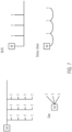
- Fig. 7 four different embodiments of network topologies are illustrated, which can be used according to the present invention.
- the topology may be ether bridge, star, bus, or daisy chain topology.
- a corresponding ether bridge topology is on the upper left side, star topology on the lower left side, bus topology on the upper right side and daisy chain topology on the lower right side.
- Summarizing the present invention discloses a bidirectional communication and control system via powerline for emergency lighting which includes a central power system CPS and emergency light lamp modules ELMs and/or sensor modules SM.
- CPS central power system
- ELMs emergency light lamp modules
- SM sensor modules
- the performance of other system known from practice can be enhanced according to the present application.
- bidirectional communication between CPS and ELMs/SMs is possible for both voltages used in such a system, see AC and DC.
- the powerline communication is possible for all types of network topologies and different frequencies are covered, see CENB and FCC-2 mentioned above. It is further possible to improve the PLC performance as for parallel end circuits. Transmitters and receivers are in parallel at the coordinator or master.
- a remote data analysis is possible to enable prognostics and health monitoring of ELMs or SMs.
Landscapes
- Cable Transmission Systems, Equalization Of Radio And Reduction Of Echo (AREA)
- Circuit Arrangement For Electric Light Sources In General (AREA)
Abstract
Description
- The present invention discloses a bidirectional communication and control system via powerline for emergency lighting using a powerline and further comprising a central power system CPS connected to the mains, a number of emergency lamp modules ELMs and/or sensor modules SMs. The ELMs are connected to at least one luminaire or one string of luminaires, such as LEDs. The corresponding ELMs and SMs are connected to each other by powerline and to the central power system CPS, wherein such powerline communication PLC is used for bidirectional communication between CPS and each ELM/SM. The purpose for using such PLC is to remove double wiring for power and data communication and keep only the power cable or powerline to transmit the data along with power between devices.
- However, such known bidirectional communication and control system for emergency lighting offer limited connectivity solutions between CPS, ELMs and SMs. For example, increased affordance, adaptive evacuation, monitor/non-monitored ELMs in same end circuit upgrade, and few others are not directly possible by present communication technologies without, for example adding additional hardware and firmware solutions or some other additional modules.
- Therefore, it is an the object of the application to improve such bidirectional communication and control system for emergency lighting such that true bidirectional communication between CPS and ELM/SM is possible for all types of network topologies and which is possible for both Vac or Vdc powerlines,at least in the ranges of 175 Vac to 275 Vac or 150 Vdc to 290 Vdc. Moreover, one particular architecture of the bidirectional communication and control system for emergency lighting should be provided which is also usable for all types of network topologies.
- According to the present invention, there is a single solution to cover CENB, namely, CENELEC B frequency band and FCC-2, which means upper FCC frequency band. The CENELEC B frequency band has frequencies of about 95kHz to 125kHz and the upper FCC frequency band has frequencies in the range of 150kHz to 500kHz.
- According to the present invention, such bidirectional communication and control system for emergency lighting described above is improved to solve those objects in that there is at least one communication unit CU connected between CPS and ELMs/SMs to coordinate communication between CPS and ELMs/SMs and to communicate with CPS and ELMs/SMs, which CU comprises at least a filter unit, a PLC modem, a coupling transformer, as well as transmitter and receiver filter units.
- The corresponding communication unit may be directly assigned to the CPS or may even be part of same. The filter unit is used to attenuate frequencies, in particular the carrier frequencies. For example it can be realized as an impedance upper and EMI filter unit. The corresponding PLC modem transmits, receives, encodes and decodes data, and the coupling transformer couples transmitter data and decouples receiver data. Corresponding transmitter and/or receiver filter units are used to filter transmitter data to be coupled with powerline via coupling transformer and/or the receiver filter unit filters receiver signals except the carrier frequency. In particular the transmitter filter unit is optional.
- Consequently, according to the present invention, there is a configurable, modular solution proposed, which can work on more than one narrow band frequencies, such as CENELEC B (CENB), but which can also be used for the corresponding FCC-2 frequencies. In general, it is usable for all types of network topologies and allows to bidirectional communication for corresponding AC and DC power sources.
- According to the present application, it is further possible that the CU is connected to a number of strings in parallel, wherein each string comprises a number of ELMs and/or SMs. Each ELM is then connected to a corresponding luminaire or string of luminaires.
- To provide an easy possibility to change the powerlines between mains and a secondary power source based on requirements, the CU can be connected to a control and switchover unit of the CPS.
- Such control and switchover unit CSU is in particular configured to switch between single or three phase mains and a second power source, in particular a battery system.
- The corresponding communication unit of the CPS acts as a coordinator or master for communication between CPS and ELMs/SMs. It will communicate with a CPS system controller and will relay info and instructions between CPS and ELMs/SMs.
- With respect to the different ELMs or SMs, it is further of advantage, in case those comprise a communication unit and a corresponding driver unit, wherein all ELMs/SMs are connected in parallel to the PLC. Moreover, each ELM and/or SM may further comprise a controller or and ELM driver or SM circuitry. The ELM driver may comprise a buck converter circuitry, a module controller and at least one sensing circuitry. The buck converter is generally used to convert a power level for any connected string of luminaires. The corresponding module controller is used to control the buck converter as well as communicate with a communication unit to route corresponding instructions. Moreover, voltage, current and temperature may be detected by the sensing circuitry for prognostics and diagnostics of the string of luminaires and any other ELM circuitry.
- The corresponding SM will also comprise a controller to communicate sensor data with the communication unit and may have at least one sensor.
- The communication unit may have further parts, such as for example an isolated power supply unit PSU, PLC Modem, a transmitter line driver, TX/RX Filters and coupling transformer wherein the isolated PSU is to provide power to corresponding low voltage circuits. The Tx filter and transmitter line driver are connected to PLC modem and are in particular used to amplify and filter TX data to be coupled with power line via coupling transformer. Corresponding CUs can also be part of each ELM/SM and can be connected in parallel with corresponding transmitter and receiver units of the CPS. The coupling transformer may be used to couple Tx data and to decouple Rx data. However, the Tx filter is optional.
- The CPS may further comprise a line driver protection unit connected to the line drivers of the CUs connected to ELMs/SMs and/or comprise a PLC module. The line driver protection module takes care of thermal and other electrical overstress protection logic for all TX line drivers.
- A corresponding ELM may be assigned to a string of luminaires but also to a luminaire or part of same. The corresponding SM is part of such string of luminaires and may be integrated in an ELM or can be a stand alone module.
- Furthermore, there may be a network stabilizer connected to at least one string of ELMs/SMs and it is further possible according to the present application that a communication between CPS and ELMs/SMs is a parallel communication between CU of CPS and CUs of ELMs/SMs.
- As already said, each SM may be a standalone module or may be integrated in a corresponding ELM.
- It was already said that according to the present invention, all types of network topologies are possible, which network topologies are for example, bus, star, daisy chain or either bridge topology.
- In the following, the invention will be described with respect to the accompanied drawings.
- Fig. 1
- is a corresponding system architecture of the bidirectional communication and console system for emergency lighting;
- Fig. 2
- corresponds to
Fig. 1 with some further details of corresponding communication unit; - Fig. 3
- is simplified model of ELM/SM architecture;
- Fig. 4
- illustrates the arrangement of such ELM/SM according to
Fig. 3 with powerline; - Fig. 5
- discloses some further detail of an ELM or SM;
- Fig. 6
- is an embodiment of a communication unit; and
- Fig. 7
- different network topologies.
-
Fig. 1 illustrates one kind of architecture of corresponding bidirectional communication and control system 1. This comprises a central power system CPS 2 with connection to mains 3, a control and switchover unit CSU 14, asecond power source 15 and a communication unit CU of the CPS 2, seereference numeral 8. The mains may be single or three phase AC and thesecond power source 15 may be a battery. The controller and switchover unit CSU 14 changes the powerlines between primary, see mains, and secondary power source based on requirements. - The CU 8 acts as a coordinator/master for communication between the CPS and a plurality of emergency lighting
lamp modules ELMs 4 and/orsensor modules SMs 6. The corresponding ELMs, SMs are arranged in parallel with respect to a corresponding powerline communication PLC 7 in form of a powerline 31. Each of the ELMs may be connected to a string of luminaire or may also be integrated in a particular luminaire. -
Fig. 2 is a particular embodiment of the present application, according to which a number ofCUs 8 are arranged in parallel and are connected to the CPS 2. For this reason, the CPS 2 comprises a coordinator with atransmitter unit 26 and a receiver unit 27, which are used for transmitter paralleling and control and receiver summing. InFig. 2 , there are fourcorresponding communication units 8, each connected to circuit in and circuit out, see alsoFig. 6 , wherein there is this particular transmitter paralleling and control, seereference numeral 26, 32 according to which, it is possible to send corresponding signal from this coordinator to all four communication units. - In the other way, there is the corresponding receiver summing, see reference numeral 27, 33, which receives data from the ELMs/SMs and will coordinate same by corresponding firmware so that one data will be available on powerline, wherein the receiver summing module will physically add signals available from all other receiver modules of the
communication units 8, to make it available for the coordinator at the CPS for decoding. There is a further linedriver protection unit 28, which takes care of thermal and other electrical overstress protection logic for allother line driver 25 in the different circuits. - Moreover, there is a corresponding
powerline communication modem 10, which allows a corresponding powerline communication. - The CPS further comprises an
isolated power supply 24 to submit corresponding power to thePLC modem 10, corresponding line drives 25 of thecommunication unit 8, etc. - In
Fig. 3 , a simplified illustration of an emergency lightinglamp module ELM 4 orsensor module SM 6. Those are connected with a powerline and each of the module comprises, for example, a modulecommunication unit MCU 16 and driver unit 17.Thecommunication unit 16 is used for communication with a corresponding CU of the CPS and thedriver unit 17 is used to drive any luminaire connected to the emergency lighting lamp module. - In
Fig. 4 , a number of ELMs and SMs are connected in parallel with the corresponding powerline communication or powerlines 31. - In
Fig. 5 , corresponding emergency lighting lamp module ELM and sensor module SM, seereference numerals - The corresponding
ELM 4 comprises abuck converter 19, anELM controller 20, and asensing circuitry 21. Thebuck converter 19 is used to convert a power level received from isolated PSU, see alsoFig. 2 or also followingFig. 6 , and to submit same to thestring 5 of luminaires . Such string may be provided in the upper and lower part ofFig. 5 , wherein in the lower part, a corresponding sensor module is integrated in the ELM. However, the SM may of course be a standalone unit. - The corresponding
controller 20 controls the buck converter as well as the communication with the communication unit to route instructions and thesensing circuitry 21 detects voltage of the luminaire, current or temperature for prognostics and diagnostics of the corresponding luminaire. - In the lower part of
Fig. 5 , the same parts are illustrated for the ELM, wherein additional parts for the SM are added, seecontroller 22 andsensors 23. The sensors may be similar to thesensing circuitry 21 and the controller will communicate corresponding sensor data of thesensors 23 to the communication unit. - Thus, according to the present invention, the SM can be an independent module and connected to the powerlines. In such a case, both are connected to the same powerlines via through connections or parallel connections. Moreover, the SM may also be integrated within the ELM.
- With respect to voltage, current and temperature, a corresponding prognostics and health monitoring will be possible, wherein analog signals of voltage, current and temperature are continuously monitored at real-time. A data analysis is performed to decide, for example, particular failure modes such as single or more luminaire failure in open mode, luminaire short circuit, luminaire over current, luminaire over voltage, luminaire degradation, and other associated circuit failures, such as open or short, sensor malfunction, sensor failure or the like. The light source of the luminaire may be one or more LEDs.
- Corresponding ELM status will also be continuously shared with the coordinator or master of the system/CPS over the powerline, such status is for example on, off, runtime, power consumption or other associated parameters.
- According to the invention and the different communication units, it is possible to upgrade or update the corresponding firmware of the driver's remote via the proposed powerline communication. Such firmware update is for example required to address bugs. Moreover, it may be possible to calibrate parameters of the corresponding luminaire driver. Also, those calibration parameters are remotely updated via the proposed powerline communication. Corresponding prognostics and health monitoring uses a voltage, current and temperature to identify any failure mode or any upcoming possible failure for predictive maintenance.
- In
Fig. 6 , acommunication unit 8 according to the present invention is illustrated in more detail. Thecorresponding communication unit 8 comprises different parts, such as afilter unit 9, aPLC modem 10, an optionaltransmitter filter unit 12, areceiver filter unit 13, acoupling transformer 11, and atransmitter line driver 25. Theisolated PSU 20 is connected to power-inlines 26 and to thefilter unit 9, and further to thePLC modem 10, and thetransmitter line driver 25. Thetransmitter line driver 25 is then connected to thetransmitter filter unit 12 and this is connected to the correspondingcoupling transformer 11. This is connected to thereceiver filter unit 13 and this is further connected toPLC modem 10. Thecoupling transformer 11 is also connected to a power-out line 34. - The
corresponding filter unit 9 is an impedance upper and EMI filter to attenuate frequencies in particular carrier frequencies. Theisolated PSU 24 provides power to low voltage circuits. - The
PLC modem 10 transmits, receives, and encodes and decodes data received by the powerline. Thecoupling transformer 11 couples transmitter data and decouples receiver data. - The corresponding
transmitter line driver 25 and optionaltransmitter filter unit 12 are used to amplify and filter transmitter data to be coupled with a powerline via the correspondingcoupling transformer 11. Thereceiver filter unit 13 is used to filter receiver signal except carrier frequency. - In
Fig. 7 , four different embodiments of network topologies are illustrated, which can be used according to the present invention. There is always the corresponding master or coordinator connected to the different modules, wherein the topology may be ether bridge, star, bus, or daisy chain topology. A corresponding ether bridge topology is on the upper left side, star topology on the lower left side, bus topology on the upper right side and daisy chain topology on the lower right side. - Summarizing the present invention discloses a bidirectional communication and control system via powerline for emergency lighting which includes a central power system CPS and emergency light lamp modules ELMs and/or sensor modules SM. The performance of other system known from practice can be enhanced according to the present application. For example, bidirectional communication between CPS and ELMs/SMs is possible for both voltages used in such a system, see AC and DC. The powerline communication is possible for all types of network topologies and different frequencies are covered, see CENB and FCC-2 mentioned above. It is further possible to improve the PLC performance as for parallel end circuits. Transmitters and receivers are in parallel at the coordinator or master. Moreover, a remote data analysis is possible to enable prognostics and health monitoring of ELMs or SMs.
Claims (20)
- Bidirectional communication and control system (1) for emergency lighting comprising a central power system (2), CPS, connected to mains (3) a number of emergency lamp modules (4), ELMs, each connected to at least one luminaire or one string (5) of luminaires and/or at least a sensor module (6), SM, those modules (4,6) connected to each other and to the CPS (2) via a power line communication (7), PLC, for bidirectional communication between CPS and each ELM/SM, wherein at least one communication unit (8), CU, is connected between CPS and ELMs/SM to coordinate communication between CPS and ELMs/SM and to communicate with CPS and ELMs/SM, which CU (8) comprises at least a filter unit (9), a PLC modem (10), a coupling transformer (11), and a transmitter and/or receiver filter unit (12, 13).
- System according to claim 1, wherein the CU (8) is connected to a number of strings in parallel, wherein each string comprises a number of ELMs and/or SMs.
- System according to claim 1 or 2, wherein the CU (8) is connected to a control and switchover unit (14), CSU, of the CPS (2).
- System according to one of the previous claims, wherein the CSU (14) is configured to switch between single or three phase mains (3) and a second power source (15), in particular a battery system.
- System according to one of the previous claims, wherein each ELM and/or SM comprises a module communication unit (16), MCU, and a driver unit (17), wherein all ELMs/SMs are connected in parallel to the PLC (7).
- System according to one of the previous claims, wherein each ELM and/or SM comprises a module controller (20,22).
- System according to one of the previous claims, wherein the ELM driver unit (17) comprises a buck converter circuitry (19), an ELM module controller (20) and at least one sensing circuitry (21).
- System according to one of the previous claims, wherein the SM driver unit (17) comprises a SM module controller (22) and at least one sensor (23).
- System according to one of the previous claims, wherein the ELM driver unit (17) is connected to at least one LED-string with a number of LEDs connected in parallel.
- System according to one of the previous claims, wherein the CU (8) further comprises an in particular isolated power supply unit (24), PSU, and a transmitter line driver (25), said isolated PSU (24) connected to the PLC modem (10) and to power-in lines (26) of the CU (8) to provide power to corresponding low voltage circuits and the transmitter line driver (25) connected to the transmitter filter unit (12), isolated PSU (24) and PLC modem (10) to amplify and filter Tx data to be coupled with power line via the coupling transformer (11).
- System according to one of the previous claims, wherein the module communication units (16) of ELMs/SMs are connected in parallel with transmitter unit (26) and receiver unit (27) of the CPS (2).
- System according to one of the previous claims, wherein the CPS (2) comprises a line driver protection unit (28) connected to line drivers (25) of the CUs (16) and/or comprising a PLC modem (29) connected to transmitter unit (26) and receiver unit (27) and to a line driver protection unit (28).
- System according to one of the previous claims, wherein a network stabilizer (30) is connected to at least one string of ELMs/SMs (4, 6).
- System according to one of the previous claims, wherein a communication between CPS (2) and ELMs/SMs (4, 6) is preferably a parallel communication between CU (8) of CPS (2) and MCUs (16).
- System according to one of the previous claims, wherein the SM (6) is integrated in the ELM (4).
- System according to one of the previous claims, wherein the ELM (4) is assigned to a luminaire or is part of the luminaire.
- System according to one of the previous claims, wherein CPS (8) and ELMs/SMs (4, 6) are connected in a cable network topologies, such as bus, star, daisy chain or either bridge topology.
- System according to one of the previous claims, wherein the system is adapted to work at least in frequency ranges of 95kHz to 125KHz, CENB, and 150 KHz to 500 KHz,FCC-2.
- System according to one of the previous claims, wherein the system is adapted to monitor at least voltage, current and temperature preferably in real time for signature data analysis in particular to identify any failure mode or any upcoming possible failure for predictive maintenance .
- System according to one of the previous claims, wherein the system is adapted to exchange data for at least upgrading/updating and configuring any ELMs/SMs.
Applications Claiming Priority (2)
| Application Number | Priority Date | Filing Date | Title |
|---|---|---|---|
| IN202111053247 | 2021-11-19 | ||
| GB2200949.2A GB2615298A (en) | 2021-11-19 | 2022-01-25 | Bidirectional communication and control system via powerline for emergency lighting |
Publications (1)
| Publication Number | Publication Date |
|---|---|
| EP4185075A1 true EP4185075A1 (en) | 2023-05-24 |
Family
ID=84330307
Family Applications (1)
| Application Number | Title | Priority Date | Filing Date |
|---|---|---|---|
| EP22206360.4A Pending EP4185075A1 (en) | 2021-11-19 | 2022-11-09 | Bidirectional communication and control system via powerline for emergency lighting |
Country Status (1)
| Country | Link |
|---|---|
| EP (1) | EP4185075A1 (en) |
Citations (4)
| Publication number | Priority date | Publication date | Assignee | Title |
|---|---|---|---|---|
| FR2658010A1 (en) * | 1990-02-08 | 1991-08-09 | Sgs Thomson Microelectronics | Emergency lighting system for installations powered by electric mains |
| WO2003102890A2 (en) * | 2002-06-03 | 2003-12-11 | Systel Development & Industries Ltd. | Multiple channel ballast and networkable topology and system including power line carrier applications |
| EP2874472A1 (en) * | 2013-11-14 | 2015-05-20 | Renesas Electronics Corporation | LED lamp, power-line network system, writing method for location information, projector, data processing method and collision avoidance system |
| WO2018037044A1 (en) * | 2016-08-23 | 2018-03-01 | Tridonic Gmbh & Co Kg | Emergency lighting |
-
2022
- 2022-11-09 EP EP22206360.4A patent/EP4185075A1/en active Pending
Patent Citations (4)
| Publication number | Priority date | Publication date | Assignee | Title |
|---|---|---|---|---|
| FR2658010A1 (en) * | 1990-02-08 | 1991-08-09 | Sgs Thomson Microelectronics | Emergency lighting system for installations powered by electric mains |
| WO2003102890A2 (en) * | 2002-06-03 | 2003-12-11 | Systel Development & Industries Ltd. | Multiple channel ballast and networkable topology and system including power line carrier applications |
| EP2874472A1 (en) * | 2013-11-14 | 2015-05-20 | Renesas Electronics Corporation | LED lamp, power-line network system, writing method for location information, projector, data processing method and collision avoidance system |
| WO2018037044A1 (en) * | 2016-08-23 | 2018-03-01 | Tridonic Gmbh & Co Kg | Emergency lighting |
Similar Documents
| Publication | Publication Date | Title |
|---|---|---|
| US6256544B1 (en) | Apparatus and method for controlling functional units in a manufacturing installation | |
| US20040196844A1 (en) | Control system including controller and field devices | |
| WO2014154274A1 (en) | Dual-mode luminaire controllers | |
| US20130249442A1 (en) | Digital Lighting Sub-Network Interface | |
| US20140143607A1 (en) | Dedicated Network Diagnostics Module for a Process Network | |
| US20130200810A1 (en) | Led lighting devices | |
| GB2615298A (en) | Bidirectional communication and control system via powerline for emergency lighting | |
| US20230118452A1 (en) | Input/output module, standard input/output module unit, and safety circuit unit | |
| JP5399882B2 (en) | Lighting system | |
| WO2011043599A2 (en) | Combined wireless and touch light switch device | |
| JP2008228427A (en) | Switching system | |
| US9577470B2 (en) | Electrical and/or electronic supply circuit and method for providing a supply voltage | |
| CN116828976A (en) | Lighting systems and lighting fixtures for indoor cultivation applications | |
| US20240276622A1 (en) | Controller for an indoor grow lighting system | |
| KR101677131B1 (en) | Lighting control system using Bluetooth | |
| EP3772237B1 (en) | Arrangement for controlling lighting in a vehicle | |
| KR100823086B1 (en) | Street light remote monitoring and control system using low power wireless communication technology | |
| JP5988126B2 (en) | Equipment control system | |
| US20120109396A1 (en) | Industrial process communication system | |
| HK40039842B (en) | Arrangement for controlling lighting in a vehicle | |
| JPH03201096A (en) | Wireless alarm system | |
| JP4548275B2 (en) | Emergency light automatic inspection system | |
| HK40039842A (en) | Arrangement for controlling lighting in a vehicle | |
| TWI827337B (en) | Communication terminals and communication systems | |
| CN121763077A (en) | Broken line detection device and detection method for signal line of ship automation system |
Legal Events
| Date | Code | Title | Description |
|---|---|---|---|
| PUAI | Public reference made under article 153(3) epc to a published international application that has entered the european phase |
Free format text: ORIGINAL CODE: 0009012 |
|
| STAA | Information on the status of an ep patent application or granted ep patent |
Free format text: STATUS: THE APPLICATION HAS BEEN PUBLISHED |
|
| AK | Designated contracting states |
Kind code of ref document: A1 Designated state(s): AL AT BE BG CH CY CZ DE DK EE ES FI FR GB GR HR HU IE IS IT LI LT LU LV MC ME MK MT NL NO PL PT RO RS SE SI SK SM TR |
|
| STAA | Information on the status of an ep patent application or granted ep patent |
Free format text: STATUS: REQUEST FOR EXAMINATION WAS MADE |
|
| 17P | Request for examination filed |
Effective date: 20231124 |
|
| RBV | Designated contracting states (corrected) |
Designated state(s): AL AT BE BG CH CY CZ DE DK EE ES FI FR GB GR HR HU IE IS IT LI LT LU LV MC ME MK MT NL NO PL PT RO RS SE SI SK SM TR |
|
| STAA | Information on the status of an ep patent application or granted ep patent |
Free format text: STATUS: EXAMINATION IS IN PROGRESS |
|
| 17Q | First examination report despatched |
Effective date: 20240802 |