EP4184768A1 - Converter and method of operating a converter - Google Patents
Converter and method of operating a converter Download PDFInfo
- Publication number
- EP4184768A1 EP4184768A1 EP21208714.2A EP21208714A EP4184768A1 EP 4184768 A1 EP4184768 A1 EP 4184768A1 EP 21208714 A EP21208714 A EP 21208714A EP 4184768 A1 EP4184768 A1 EP 4184768A1
- Authority
- EP
- European Patent Office
- Prior art keywords
- converter
- limit
- current
- network
- voltage
- Prior art date
- Legal status (The legal status is an assumption and is not a legal conclusion. Google has not performed a legal analysis and makes no representation as to the accuracy of the status listed.)
- Pending
Links
Images

Classifications
-
- H—ELECTRICITY
- H02—GENERATION; CONVERSION OR DISTRIBUTION OF ELECTRIC POWER
- H02M—APPARATUS FOR CONVERSION BETWEEN AC AND AC, BETWEEN AC AND DC, OR BETWEEN DC AND DC, AND FOR USE WITH MAINS OR SIMILAR POWER SUPPLY SYSTEMS; CONVERSION OF DC OR AC INPUT POWER INTO SURGE OUTPUT POWER; CONTROL OR REGULATION THEREOF
- H02M1/00—Details of apparatus for conversion
- H02M1/0003—Details of control, feedback or regulation circuits
- H02M1/0025—Arrangements for modifying reference values, feedback values or error values in the control loop of a converter
-
- H—ELECTRICITY
- H02—GENERATION; CONVERSION OR DISTRIBUTION OF ELECTRIC POWER
- H02J—ELECTRIC POWER NETWORKS; CIRCUIT ARRANGEMENTS OR SYSTEMS FOR SUPPLYING OR DISTRIBUTING ELECTRIC POWER; SYSTEMS FOR STORING ELECTRIC ENERGY
- H02J3/00—Circuit arrangements for AC mains or AC distribution networks
- H02J3/001—Arrangements for handling faults or abnormalities, e.g. emergencies or contingencies
-
- H—ELECTRICITY
- H02—GENERATION; CONVERSION OR DISTRIBUTION OF ELECTRIC POWER
- H02J—ELECTRIC POWER NETWORKS; CIRCUIT ARRANGEMENTS OR SYSTEMS FOR SUPPLYING OR DISTRIBUTING ELECTRIC POWER; SYSTEMS FOR STORING ELECTRIC ENERGY
- H02J3/00—Circuit arrangements for AC mains or AC distribution networks
- H02J3/001—Arrangements for handling faults or abnormalities, e.g. emergencies or contingencies
- H02J3/0012—Arrangements for handling faults or abnormalities, e.g. emergencies or contingencies characterised by the contingency detection means in AC networks, e.g. using phasor measurement units [PMU], synchrophasors or contingency analysis
-
- H—ELECTRICITY
- H02—GENERATION; CONVERSION OR DISTRIBUTION OF ELECTRIC POWER
- H02J—ELECTRIC POWER NETWORKS; CIRCUIT ARRANGEMENTS OR SYSTEMS FOR SUPPLYING OR DISTRIBUTING ELECTRIC POWER; SYSTEMS FOR STORING ELECTRIC ENERGY
- H02J3/00—Circuit arrangements for AC mains or AC distribution networks
- H02J3/38—Arrangements for feeding a single network from two or more generators or sources in parallel; Arrangements for feeding already energised networks from additional generators or sources in parallel
- H02J3/381—Dispersed generators
-
- H—ELECTRICITY
- H02—GENERATION; CONVERSION OR DISTRIBUTION OF ELECTRIC POWER
- H02M—APPARATUS FOR CONVERSION BETWEEN AC AND AC, BETWEEN AC AND DC, OR BETWEEN DC AND DC, AND FOR USE WITH MAINS OR SIMILAR POWER SUPPLY SYSTEMS; CONVERSION OF DC OR AC INPUT POWER INTO SURGE OUTPUT POWER; CONTROL OR REGULATION THEREOF
- H02M1/00—Details of apparatus for conversion
- H02M1/32—Means for protecting converters other than automatic disconnection
- H02M1/325—Means for protecting converters other than automatic disconnection with means for allowing continuous operation despite a fault, i.e. fault tolerant converters
-
- H—ELECTRICITY
- H02—GENERATION; CONVERSION OR DISTRIBUTION OF ELECTRIC POWER
- H02J—ELECTRIC POWER NETWORKS; CIRCUIT ARRANGEMENTS OR SYSTEMS FOR SUPPLYING OR DISTRIBUTING ELECTRIC POWER; SYSTEMS FOR STORING ELECTRIC ENERGY
- H02J2101/00—Supply or distribution of decentralised, dispersed or local electric power generation
- H02J2101/20—Dispersed power generation using renewable energy sources
- H02J2101/28—Wind energy
-
- Y—GENERAL TAGGING OF NEW TECHNOLOGICAL DEVELOPMENTS; GENERAL TAGGING OF CROSS-SECTIONAL TECHNOLOGIES SPANNING OVER SEVERAL SECTIONS OF THE IPC; TECHNICAL SUBJECTS COVERED BY FORMER USPC CROSS-REFERENCE ART COLLECTIONS [XRACs] AND DIGESTS
- Y02—TECHNOLOGIES OR APPLICATIONS FOR MITIGATION OR ADAPTATION AGAINST CLIMATE CHANGE
- Y02E—REDUCTION OF GREENHOUSE GAS [GHG] EMISSIONS, RELATED TO ENERGY GENERATION, TRANSMISSION OR DISTRIBUTION
- Y02E60/00—Enabling technologies; Technologies with a potential or indirect contribution to GHG emissions mitigation
- Y02E60/60—Arrangements for transfer of electric power between AC networks or generators via a high voltage DC link [HVCD]
Definitions
- the present invention relates to a converter comprising an AC side to connect to an AC network (AC grid), and a converter control configured to set a current reference limit to limit a converter current.
- the converter control usually limits the converter currents which could otherwise exceed the current carrying capacity of the converter (or its components). Limiting the current reference means that no values of the current reference above a certain limit (threshold) are allowed by the converter control.
- VSC voltage sourced
- the transmission capacity of converters is observed to be increasing.
- the corresponding ratings are expected to lie the range of 2000 MW up to 4000 MW in the future.
- Higher ratings potentially cause higher short circuit current contribution in case of a fault (e.g. a phase-to-phase or a ground fault on the AC side of the converter due to cable or cable termination damages).
- green insulation gases are gaining market share for such equipment, which often have reduced current carrying, making and breaking capabilities. Therefore it is important to maintain the potentially occurring stresses within the capabilities of the corresponding components, particularly generators and switchgears.
- the object of the invention is to provide an aforementioned converter as reliable as possible.
- the converter control is configured to reduce said limit in case of a fault detected in said AC network.
- the converter control can be equipped with an additional module (control block) for the operation of reducing the current reference limit.
- additional module can be implemented as a part of and included in the usual converter control system (e.g. as an additional feedback loop).
- the current reference limit is preferably reduced as soon as the fault is detected by a suitable detection means. An occurrence of a fault can be for example detected as a voltage drop in the AC network measured by a suitable voltage measurement system. The decrease of the voltage reference value can therefore be used as a fault indicator.
- the present invention enables the limitation of potential short circuit stresses caused for example by an HVDC converter through an AC voltage dependent current limitation.
- Limiting the short circuit currents allows utilizing the economic benefit of connecting renewable energy generators directly to an HVDC converter station (e.g. offshore wind park with turbines connected directly to an HVDC converter station without the need of several additional AC collector platforms). It particularly allows to increase the rating of renewable energy resources connected through a VSC HVDC (e.g offshore wind parks) without increasing the short circuit stresses in the generation equipment (e.g. in a generator switchgear). This in turn enables using standardized medium or high voltage components which in addition provides cost advantages. Furthermore, the present invention does not have negative effects on the dynamic performance of the converter.
- the adaptive converter admittance presented herein also allows to continue the active damping of harmonics which takes place during steady state conditions.
- the converter control is configured to reduce said limit as a function of a voltage reference value.
- a voltage reference value may lie between 0% and 100% of the nominal voltage of the AC grid under operating conditions of the converter (the setup of the converter control usually involves the knowledge of the nominal AC voltage of the respective grid where the converter is to be operated).
- a voltage reference provided by an alternating current control (ACCC) to a converter modulator is reduced by a central converter control unit to limit the converter side currents of the converter.
- the voltage reference can be used to quickly identify fault conditions in the AC network.
- the above-mentioned function preferably is non-linear.
- a simple example of a non-linear function is a (continuous) piecewise linear function, where the linear sections have different slopes.
- the non-linearity of the function advantageously reflects the non-linearity of the respective transmission system.
- the function has a maximum function value equal to one for voltage reference values exceeding 85%, more preferably exceeding 90%, of a nominal AC voltage of the AC network. Accordingly, the reduction of current limits only takes place outside the typical steady state voltage band.
- the converter is a modular multilevel converter.
- a modular multilevel converter is particularly characterized by at least one converter valve comprising a series circuit of switching modules.
- Each switching module comprises its own energy storage element (e.g. a capacitor) and semiconductor switches. Every switching module can be individually controlled to provide certain module voltage at its terminals (e.g. the capacitor voltage or a zero voltage in case of a half-bridge module).
- a modular multilevel converter for HVDC applications usually comprises three parallel phase modules, wherein each of the phase modules has two converter arms (valves) arranged between a respective AC connection and one of two DC poles. Every converter arm comprises an arm inductance (choke) and a series of submodules, wherein each submodule comprises semiconductor switches and an energy storage, e.g. a capacitor.
- the semiconductor switches and the capacitor of said submodule are e.g. arranged to form a so-called half-bridge circuit, assembled to form a multilevel arrangement.
- the converter of the present invention is preferably used in a power system comprising a renewable power source connected via said converter to said AC network.
- the renewable power source can particularly be a wind park comprising wind turbines and corresponding generators.
- Standard class renewable generators (e.g. in wind turbines) are equipped with standardized medium or high voltage components with relatively low current carrying capabilities. Therefore, it is essential to maintain the potentially occurring stresses within their capabilities.
- the use of a converter and/or converter control in accordance with the present invention enables the limitation of potential short circuit stresses caused in the connected array cables, the wind turbines and especially the wind turbine circuit breakers. Thus, it enables the usage of standard class wind turbines while utilizing all benefits of a direct integrated HVDC connection on medium or high voltage potential, e.g. at 66kV AC or above.
- Another object of the invention is to provide a method of operating a converter as reliable as possible.
- a method of operating a converter comprising an AC side to connect to an AC network and a converter control.
- Said method comprises the steps of setting a current reference limit to limit a converter current and reducing the limit in case of a fault in said AC network.
- the voltage reference output of a converter modulator is continuously observed. As long as no fault occurs, the steady state limits are kept. As soon as a fault is detected (e.g. if the voltage reference drops below a given threshold), the AC voltage dependent current limitation is used. Accordingly, the current limits of the converter control system (e.g. a grid forming control system) are adjusted.
- the corresponding current references can be issued to a current controller of the converter control system.
- the current controller on its output provides then the corresponding voltage reference which can be issued to the respective converter modulator.
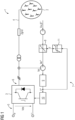
- FIG. 1 depicts a power system 1 comprising a renewable power source 2 (a wind park with a plurality of wind turbines) connected to a converter 3 via an AC network 4.
- the network impedance is denoted as Zgrid.
- the power generated in the power source 2 fed by the converter 3 into an HVDC line and further transferred to a power supply grid with multiple loads.
- the converter 3 is a voltage sourced converter, in particular a modular multilevel converter having a DC side 5 to connect to the HVDC line and an AC side 6 to connect to the AC network 4.
- the DC voltage on the DC side 5 of the converter 3 is denoted by Vdc.
- a converter control 7 is configured to control the semiconductor switching components of the converter 3.
- the converter control 7 comprises a block or module 8 configured to set a current reference limit to limit a converter current.
- a current reference value Iac* is provided at the output of the block 8.
- the current reference Iac* is compared with a measured actual current Iac, wherein an alternating current control 9 provides a voltage reference V* based on the difference between Iac* and Iac.
- the voltage reference V* is forwarded to a modulator 10 configured to provide switching signals for the switching modules of the converter 3 (respectively for the semiconductor switching units of the switching modules).
- the converter control 7 further comprises an AC voltage dependent current limitation block 11.
- the reference voltage V* is provided as input to the AC voltage dependent current limitation block 11.
- the AC voltage dependent current limitation block 11 provides as its output a limiting factor F which is a function of a voltage reference value V*.
- the limiting factor F is forwarded to the block 8 to adjust the converter current limits.
- Figure 2 depicts a diagram showing an example of a non-linear functional dependence between the limiting factor F and the reference voltage V*.
- the functional dependence shown in figure 2 is piecewise linear, composed of a plurality of linear sections.
Landscapes
- Engineering & Computer Science (AREA)
- Power Engineering (AREA)
- Supply And Distribution Of Alternating Current (AREA)
- Inverter Devices (AREA)
Abstract
Description
- The present invention relates to a converter comprising an AC side to connect to an AC network (AC grid), and a converter control configured to set a current reference limit to limit a converter current.
- The converter control usually limits the converter currents which could otherwise exceed the current carrying capacity of the converter (or its components). Limiting the current reference means that no values of the current reference above a certain limit (threshold) are allowed by the converter control.
- The transmission capacity of converters, particularly voltage sourced (VSC) HVDC converters, is observed to be increasing. The corresponding ratings are expected to lie the range of 2000 MW up to 4000 MW in the future. Higher ratings potentially cause higher short circuit current contribution in case of a fault (e.g. a phase-to-phase or a ground fault on the AC side of the converter due to cable or cable termination damages). Moreover, driven by the demand for decarbonization, so-called green insulation gases are gaining market share for such equipment, which often have reduced current carrying, making and breaking capabilities. Therefore it is important to maintain the potentially occurring stresses within the capabilities of the corresponding components, particularly generators and switchgears.
- The object of the invention is to provide an aforementioned converter as reliable as possible.
- This object is achieved by a converter according to
claim 1. - In accordance with the invention the converter control is configured to reduce said limit in case of a fault detected in said AC network. The converter control can be equipped with an additional module (control block) for the operation of reducing the current reference limit. Such additional module can be implemented as a part of and included in the usual converter control system (e.g. as an additional feedback loop). The current reference limit is preferably reduced as soon as the fault is detected by a suitable detection means. An occurrence of a fault can be for example detected as a voltage drop in the AC network measured by a suitable voltage measurement system. The decrease of the voltage reference value can therefore be used as a fault indicator. By reducing the current reference limit, further reduction of (allowed) current reference values is achieved.
- The present invention enables the limitation of potential short circuit stresses caused for example by an HVDC converter through an AC voltage dependent current limitation. Limiting the short circuit currents allows utilizing the economic benefit of connecting renewable energy generators directly to an HVDC converter station (e.g. offshore wind park with turbines connected directly to an HVDC converter station without the need of several additional AC collector platforms). It particularly allows to increase the rating of renewable energy resources connected through a VSC HVDC (e.g offshore wind parks) without increasing the short circuit stresses in the generation equipment (e.g. in a generator switchgear). This in turn enables using standardized medium or high voltage components which in addition provides cost advantages. Furthermore, the present invention does not have negative effects on the dynamic performance of the converter. The adaptive converter admittance presented herein also allows to continue the active damping of harmonics which takes place during steady state conditions.
- Preferably, the converter control is configured to reduce said limit as a function of a voltage reference value. This means that, at least within a certain range of voltage reference values, there is a one-to-one correspondence between a given voltage reference value and a value of the limit assigned to the given voltage reference value. The range of voltage reference values may lie between 0% and 100% of the nominal voltage of the AC grid under operating conditions of the converter (the setup of the converter control usually involves the knowledge of the nominal AC voltage of the respective grid where the converter is to be operated). During grid fault conditions a voltage reference provided by an alternating current control (ACCC) to a converter modulator is reduced by a central converter control unit to limit the converter side currents of the converter. The voltage reference can be used to quickly identify fault conditions in the AC network. Accordingly, it is passed through a non-linear gain to further limit the current reference values provided by suitable control instance (e.g. a grid forming control). This solution can therefore also be interpreted as an adaptive virtual admittance which can differentiate between steady state conditions and transient faults in the grid. Quickly identifying AC fault conditions in the AC network and adaptively adjustment of the virtual admittance of the converter allows a quick reduction of converter fault currents. The AC voltage dependent current limitation effectively identifies fault conditions in the AC grid and immediately further limits converter side currents to a safe value, which guarantees grid side equipment integrity. The function can be implemented in the control system as a suitable look up table.
- The above-mentioned function preferably is non-linear. A simple example of a non-linear function is a (continuous) piecewise linear function, where the linear sections have different slopes. The non-linearity of the function advantageously reflects the non-linearity of the respective transmission system.
- Suitably, the function has a maximum function value equal to one for voltage reference values exceeding 85%, more preferably exceeding 90%, of a nominal AC voltage of the AC network. Accordingly, the reduction of current limits only takes place outside the typical steady state voltage band.
- According to an embodiment the converter is a modular multilevel converter. A modular multilevel converter is particularly characterized by at least one converter valve comprising a series circuit of switching modules. Each switching module comprises its own energy storage element (e.g. a capacitor) and semiconductor switches. Every switching module can be individually controlled to provide certain module voltage at its terminals (e.g. the capacitor voltage or a zero voltage in case of a half-bridge module). A modular multilevel converter for HVDC applications usually comprises three parallel phase modules, wherein each of the phase modules has two converter arms (valves) arranged between a respective AC connection and one of two DC poles. Every converter arm comprises an arm inductance (choke) and a series of submodules, wherein each submodule comprises semiconductor switches and an energy storage, e.g. a capacitor. The semiconductor switches and the capacitor of said submodule are e.g. arranged to form a so-called half-bridge circuit, assembled to form a multilevel arrangement.
- The converter of the present invention is preferably used in a power system comprising a renewable power source connected via said converter to said AC network. The renewable power source can particularly be a wind park comprising wind turbines and corresponding generators. Standard class renewable generators, (e.g. in wind turbines) are equipped with standardized medium or high voltage components with relatively low current carrying capabilities. Therefore, it is essential to maintain the potentially occurring stresses within their capabilities. The use of a converter and/or converter control in accordance with the present invention enables the limitation of potential short circuit stresses caused in the connected array cables, the wind turbines and especially the wind turbine circuit breakers. Thus, it enables the usage of standard class wind turbines while utilizing all benefits of a direct integrated HVDC connection on medium or high voltage potential, e.g. at 66kV AC or above.
- Another object of the invention is to provide a method of operating a converter as reliable as possible.
- This object is achieved by a converter according to claim 7.
- Accordingly, a method of operating a converter is provided, wherein the converter comprises an AC side to connect to an AC network and a converter control. Said method comprises the steps of setting a current reference limit to limit a converter current and reducing the limit in case of a fault in said AC network. According to an embodiment, the voltage reference output of a converter modulator is continuously observed. As long as no fault occurs, the steady state limits are kept. As soon as a fault is detected (e.g. if the voltage reference drops below a given threshold), the AC voltage dependent current limitation is used. Accordingly, the current limits of the converter control system (e.g. a grid forming control system) are adjusted. The corresponding current references can be issued to a current controller of the converter control system. The current controller on its output provides then the corresponding voltage reference which can be issued to the respective converter modulator.
- In the following the present invention is explained in more detail in accordance with an embodiment shown in the
figures 1 and2 . -
Figure 1 shows a schematic view of a power system with a renewable power source and a converter; -
Figure 2 shows a diagram representing a non-linear function for the converter control. -
Figure 1 depicts apower system 1 comprising a renewable power source 2 (a wind park with a plurality of wind turbines) connected to aconverter 3 via anAC network 4. The network impedance is denoted as Zgrid. The power generated in thepower source 2 fed by theconverter 3 into an HVDC line and further transferred to a power supply grid with multiple loads. Theconverter 3 is a voltage sourced converter, in particular a modular multilevel converter having a DC side 5 to connect to the HVDC line and an AC side 6 to connect to theAC network 4. The DC voltage on the DC side 5 of theconverter 3 is denoted by Vdc. - A converter control 7 is configured to control the semiconductor switching components of the
converter 3. The converter control 7 comprises a block ormodule 8 configured to set a current reference limit to limit a converter current. A current reference value Iac* is provided at the output of theblock 8. The current reference Iac* is compared with a measured actual current Iac, wherein an alternatingcurrent control 9 provides a voltage reference V* based on the difference between Iac* and Iac. The voltage reference V* is forwarded to amodulator 10 configured to provide switching signals for the switching modules of the converter 3 (respectively for the semiconductor switching units of the switching modules). The converter control 7 further comprises an AC voltage dependent current limitation block 11. The reference voltage V* is provided as input to the AC voltage dependent current limitation block 11. The AC voltage dependent current limitation block 11 provides as its output a limiting factor F which is a function of a voltage reference value V*. The limiting factor F is forwarded to theblock 8 to adjust the converter current limits. -
Figure 2 depicts a diagram showing an example of a non-linear functional dependence between the limiting factor F and the reference voltage V*. The value of the factor F is equal to one down to a voltage value V1, wherein V1 = 0.9. Below V1 the function value of F non-linearly decreases. The functional dependence shown infigure 2 is piecewise linear, composed of a plurality of linear sections.
Claims (7)
- Converter (3) comprising an AC side (6) to connect to an AC network (4), and a converter control (7) configured to set a current reference limit to limit a converter current,
characterized in that
said converter control (7) is configured to reduce said limit in case of a fault in said AC network (4). - Converter (3) according to claim 1, wherein the converter control is configured to reduce said limit as a function of a voltage reference value.
- Converter (3) according to claim 2, wherein said function is non-linear.
- Converter (3) according to claim 3, wherein the function has a maximum function value of one for voltage reference values exceeding 85%, preferable exceeding 90%, of a nominal AC voltage of the AC network (4).
- Converter (3) according to any of the preceding claims, wherein said converter (3) is a modular multilevel converter.
- Use of a converter (3) according to any preceding claims in a power system comprising a renewable power source connected to said converter (3) via said AC network.
- Method of operating a converter (3) comprising an AC side (6) to connect to an AC network (4), and a converter control (7), comprising the steps of- setting a current reference limit to limit a converter current, and- reducing said limit in case of a fault in said AC network (4).
Priority Applications (2)
| Application Number | Priority Date | Filing Date | Title |
|---|---|---|---|
| EP21208714.2A EP4184768A1 (en) | 2021-11-17 | 2021-11-17 | Converter and method of operating a converter |
| US17/988,936 US12573936B2 (en) | 2021-11-17 | 2022-11-17 | Converter and method of operating a converter |
Applications Claiming Priority (1)
| Application Number | Priority Date | Filing Date | Title |
|---|---|---|---|
| EP21208714.2A EP4184768A1 (en) | 2021-11-17 | 2021-11-17 | Converter and method of operating a converter |
Publications (1)
| Publication Number | Publication Date |
|---|---|
| EP4184768A1 true EP4184768A1 (en) | 2023-05-24 |
Family
ID=78676453
Family Applications (1)
| Application Number | Title | Priority Date | Filing Date |
|---|---|---|---|
| EP21208714.2A Pending EP4184768A1 (en) | 2021-11-17 | 2021-11-17 | Converter and method of operating a converter |
Country Status (2)
| Country | Link |
|---|---|
| US (1) | US12573936B2 (en) |
| EP (1) | EP4184768A1 (en) |
Families Citing this family (2)
| Publication number | Priority date | Publication date | Assignee | Title |
|---|---|---|---|---|
| US11962150B1 (en) * | 2023-05-30 | 2024-04-16 | North China Electric Power University | System and method of protecting power system having inverter-interfaced renewable energy sources |
| EP4492605A1 (en) * | 2023-07-11 | 2025-01-15 | General Electric Technology GmbH | Improvements relating to the control of power converters during fault conditions in power transmission networks |
Citations (2)
| Publication number | Priority date | Publication date | Assignee | Title |
|---|---|---|---|---|
| US20190052087A1 (en) * | 2016-03-10 | 2019-02-14 | Nr Electric Co., Ltd. | Method And Apparatus For Controlling Hybrid Direct-Current Transmission System |
| US20210044115A1 (en) * | 2018-02-01 | 2021-02-11 | Wobben Properties Gmbh | Method for feeding electrical power into an electrical supply network |
Family Cites Families (3)
| Publication number | Priority date | Publication date | Assignee | Title |
|---|---|---|---|---|
| US7277304B2 (en) * | 2005-09-23 | 2007-10-02 | Gm Global Technology Operations, Inc. | Multiple inverter system with single controller and related operating method |
| WO2017216575A1 (en) * | 2016-06-16 | 2017-12-21 | Swansea University | An energy management system and method for grid-connected and islanded micro-energy generation |
| EP3462559A1 (en) * | 2017-09-28 | 2019-04-03 | Vestas Wind Systems A/S | Low voltage fault ride through method for wind power plants |
-
2021
- 2021-11-17 EP EP21208714.2A patent/EP4184768A1/en active Pending
-
2022
- 2022-11-17 US US17/988,936 patent/US12573936B2/en active Active
Patent Citations (2)
| Publication number | Priority date | Publication date | Assignee | Title |
|---|---|---|---|---|
| US20190052087A1 (en) * | 2016-03-10 | 2019-02-14 | Nr Electric Co., Ltd. | Method And Apparatus For Controlling Hybrid Direct-Current Transmission System |
| US20210044115A1 (en) * | 2018-02-01 | 2021-02-11 | Wobben Properties Gmbh | Method for feeding electrical power into an electrical supply network |
Non-Patent Citations (3)
| Title |
|---|
| CUNPING WANG ET AL: "Research on the direct current control method and simulation of flexible HVDC", 2016 IEEE PES ASIA-PACIFIC POWER AND ENERGY ENGINEERING CONFERENCE (APPEEC), IEEE, 25 October 2016 (2016-10-25), pages 2023 - 2027, XP033021108, DOI: 10.1109/APPEEC.2016.7779900 * |
| ELGAMASY MAHMOUD M ET AL: "Fault detection techniques for HVDC-VSC scheme using measurement at AC side", 2017 NINETEENTH INTERNATIONAL MIDDLE EAST POWER SYSTEMS CONFERENCE (MEPCON), IEEE, 19 December 2017 (2017-12-19), pages 876 - 880, XP033325973, DOI: 10.1109/MEPCON.2017.8301283 * |
| JUN LIANG ET AL: "Control of multi-terminal VSC-HVDC transmission for offshore wind power", 13TH EUROPEAN CONFERENCE ON POWER ELECTRONICS AND APPLICATIONS, 2009 : EPE '09 ; 8 - 10 SEPT. 2009, BARCELONA, SPAIN, IEEE, PISCATAWAY, NJ, USA, 8 September 2009 (2009-09-08), pages 1 - 10, XP031541568, ISBN: 978-1-4244-4432-8 * |
Also Published As
| Publication number | Publication date |
|---|---|
| US12573936B2 (en) | 2026-03-10 |
| US20230155473A1 (en) | 2023-05-18 |
Similar Documents
| Publication | Publication Date | Title |
|---|---|---|
| Bathurst et al. | MVDC-the new technology for distribution networks | |
| Xu et al. | Grid connection of large offshore wind farms using HVDC | |
| Salomonsson et al. | Low-voltage DC distribution system for commercial power systems with sensitive electronic loads | |
| Rao | Architecture of Nan'ao multi-terminal VSC-HVDC system and its multi-functional control | |
| Friedrich | Modern HVDC PLUS application of VSC in modular multilevel converter topology | |
| CN112383229B (en) | Multi-port power electronic transformer topology and its AC/DC microgrid system | |
| CN102801177A (en) | Methods and systems for direct current power transmission | |
| CA2622089A1 (en) | Apparatus for electrical power transmission | |
| US11418034B1 (en) | Zero-sequence current balancer with a real power injector for a three-phase power system | |
| Stieneker et al. | Medium-voltage DC research grid Aachen | |
| US12573936B2 (en) | Converter and method of operating a converter | |
| US20240275176A1 (en) | Power conversion system for connecting photovoltaic plant to electric grid | |
| CN217720738U (en) | Permanent fault ride-through system for offshore flexible direct-current submarine cable | |
| De Oliveira et al. | Prospects of Voltage-Sourced Converters (VSC) applications in DC transmission systems | |
| JP7387062B1 (en) | power conversion system | |
| Maibach et al. | Full-scale medium-voltage converters for wind power generators up to 7 MVA | |
| EP4136727B1 (en) | Passive reactive compensation for a wind power plant | |
| Wang et al. | A New Current Source Converter-based Topology for Wind Energy Conversion Systems | |
| Li et al. | DC transformer based on hybrid cascaded MMC in multi-terminal HVDC transmission system | |
| Singh et al. | A Platform-less Voltage Sourced HVDC Collection System for Offshore Windfarms using Series-Connected Distributed Diode Rectifiers | |
| Ming et al. | D-Suite technologies for low-voltage distribution networks | |
| Jones et al. | Finding the missing link | |
| Nadjai et al. | Technical Considerations for the Future MVDC Grid: Application to the French Grid | |
| Klein et al. | Post-fault load flow control through grid forming wind turbines connected to bipolar HVDC system with offshore AC-side pole coupling | |
| Ma et al. | Medium-voltage DC distribution systems |
Legal Events
| Date | Code | Title | Description |
|---|---|---|---|
| PUAI | Public reference made under article 153(3) epc to a published international application that has entered the european phase |
Free format text: ORIGINAL CODE: 0009012 |
|
| STAA | Information on the status of an ep patent application or granted ep patent |
Free format text: STATUS: THE APPLICATION HAS BEEN PUBLISHED |
|
| AK | Designated contracting states |
Kind code of ref document: A1 Designated state(s): AL AT BE BG CH CY CZ DE DK EE ES FI FR GB GR HR HU IE IS IT LI LT LU LV MC MK MT NL NO PL PT RO RS SE SI SK SM TR |
|
| STAA | Information on the status of an ep patent application or granted ep patent |
Free format text: STATUS: REQUEST FOR EXAMINATION WAS MADE |
|
| 17P | Request for examination filed |
Effective date: 20230810 |
|
| RBV | Designated contracting states (corrected) |
Designated state(s): AL AT BE BG CH CY CZ DE DK EE ES FI FR GB GR HR HU IE IS IT LI LT LU LV MC MK MT NL NO PL PT RO RS SE SI SK SM TR |
|
| STAA | Information on the status of an ep patent application or granted ep patent |
Free format text: STATUS: EXAMINATION IS IN PROGRESS |
|
| 17Q | First examination report despatched |
Effective date: 20240909 |