EP4184742A1 - Flexible direct-current transmission line discharging method and apparatus, and storage medium - Google Patents
Flexible direct-current transmission line discharging method and apparatus, and storage medium Download PDFInfo
- Publication number
- EP4184742A1 EP4184742A1 EP21866072.8A EP21866072A EP4184742A1 EP 4184742 A1 EP4184742 A1 EP 4184742A1 EP 21866072 A EP21866072 A EP 21866072A EP 4184742 A1 EP4184742 A1 EP 4184742A1
- Authority
- EP
- European Patent Office
- Prior art keywords
- converter
- current
- voltage
- direct
- charging
- Prior art date
- Legal status (The legal status is an assumption and is not a legal conclusion. Google has not performed a legal analysis and makes no representation as to the accuracy of the status listed.)
- Granted
Links
Images




Classifications
-
- H—ELECTRICITY
- H02—GENERATION; CONVERSION OR DISTRIBUTION OF ELECTRIC POWER
- H02M—APPARATUS FOR CONVERSION BETWEEN AC AND AC, BETWEEN AC AND DC, OR BETWEEN DC AND DC, AND FOR USE WITH MAINS OR SIMILAR POWER SUPPLY SYSTEMS; CONVERSION OF DC OR AC INPUT POWER INTO SURGE OUTPUT POWER; CONTROL OR REGULATION THEREOF
- H02M7/00—Conversion of AC power input into DC power output; Conversion of DC power input into AC power output
- H02M7/42—Conversion of DC power input into AC power output without possibility of reversal
- H02M7/44—Conversion of DC power input into AC power output without possibility of reversal by static converters
- H02M7/48—Conversion of DC power input into AC power output without possibility of reversal by static converters using discharge tubes with control electrode or semiconductor devices with control electrode
- H02M7/483—Converters with outputs that each can have more than two voltages levels
- H02M7/4835—Converters with outputs that each can have more than two voltages levels comprising two or more cells, each including a switchable capacitor, the capacitors having a nominal charge voltage which corresponds to a given fraction of the input voltage, and the capacitors being selectively connected in series to determine the instantaneous output voltage
-
- H—ELECTRICITY
- H02—GENERATION; CONVERSION OR DISTRIBUTION OF ELECTRIC POWER
- H02J—ELECTRIC POWER NETWORKS; CIRCUIT ARRANGEMENTS OR SYSTEMS FOR SUPPLYING OR DISTRIBUTING ELECTRIC POWER; SYSTEMS FOR STORING ELECTRIC ENERGY
- H02J3/00—Circuit arrangements for AC mains or AC distribution networks
- H02J3/36—Arrangements for transfer of electric power between AC networks via high-voltage DC [HVDC] links; Arrangements for transfer of electric power between generators and networks via HVDC links
-
- H—ELECTRICITY
- H02—GENERATION; CONVERSION OR DISTRIBUTION OF ELECTRIC POWER
- H02M—APPARATUS FOR CONVERSION BETWEEN AC AND AC, BETWEEN AC AND DC, OR BETWEEN DC AND DC, AND FOR USE WITH MAINS OR SIMILAR POWER SUPPLY SYSTEMS; CONVERSION OF DC OR AC INPUT POWER INTO SURGE OUTPUT POWER; CONTROL OR REGULATION THEREOF
- H02M1/00—Details of apparatus for conversion
- H02M1/32—Means for protecting converters other than automatic disconnection
- H02M1/322—Means for rapidly discharging a capacitor of the converter for protecting electrical components or for preventing electrical shock
-
- Y—GENERAL TAGGING OF NEW TECHNOLOGICAL DEVELOPMENTS; GENERAL TAGGING OF CROSS-SECTIONAL TECHNOLOGIES SPANNING OVER SEVERAL SECTIONS OF THE IPC; TECHNICAL SUBJECTS COVERED BY FORMER USPC CROSS-REFERENCE ART COLLECTIONS [XRACs] AND DIGESTS
- Y02—TECHNOLOGIES OR APPLICATIONS FOR MITIGATION OR ADAPTATION AGAINST CLIMATE CHANGE
- Y02E—REDUCTION OF GREENHOUSE GAS [GHG] EMISSIONS, RELATED TO ENERGY GENERATION, TRANSMISSION OR DISTRIBUTION
- Y02E60/00—Enabling technologies; Technologies with a potential or indirect contribution to GHG emissions mitigation
- Y02E60/60—Arrangements for transfer of electric power between AC networks or generators via a high voltage DC link [HVCD]
Definitions
- the application relates to the technical field of power system transmission, in particular to a voltage sourced converter direct-current transmission line discharge method and device, and storage medium.
- voltage sourced converter direct-current transmission is widely used in occasions like new energy grid connection, island power supply, and offshore platform power supply, and is also a superior solution for grid interconnection and load center power supply in urbans.
- a cable is used as a transmission medium in voltage sourced converter direct-current transmission.
- a long cable has a large equivalent capacitance and will store energy while direct current passing through, it takes up to 30 to 60 minutes for the electricity accumulated on the cable to be released after voltage sourced converter direct-current transmission is out of operation, and the high voltage before discharge ends is dangerous to personal safety.
- This problem is particularly prominent in the fields of offshore platform power supply and offshore wind power grid connection.
- Offshore platforms, especially offshore oil and gas field platforms have many devices and are extremely sensitive to heat and fire sources.
- When a voltage sourced converter direct-current transmission system is out of service, it is necessary to enter a valve hall timely to check whether there are any dangerous sources, so as to ensure the safety of the whole platform.
- due to the limitation of cable discharge time people often have to wait for more than half an hour to approach the valve hall, which poses a serious safety threat.
- the first method is to add a breaker and a resistance grounding circuit to two ends of the cable to speed up discharge, that is, adding additional complex equipment in order to realize safe and fast discharge.
- the second method is to accelerate discharging by means of a direct-current energy-consuming device, which cannot be realized in a system in which no energy-consuming device is designed or installed.
- An embodiment of the application provides a discharge method for a voltage sourced converter direct-current transmission line.
- the method comprises: unlocking a converter valve; generating an additional control signal by an additional controller and superimposing the additional control signal on a reference voltage output by a main controller of the voltage sourced converter direct-current transmission system, so that the converter valve generates a harmonic current in a three-phase bridge arm of a converter; and locking the converter when a direct-current transmission line voltage is lower than a voltage setting or an average voltage of normal operating submodules in the converter bridge arm is lower than a submodule operating voltage setting.
- the method before unlocking the converter, further comprises: charging the converter by using a residual voltage of the direct-current line, determining whether the charging can be completed, and unlocking the converter valve if yes; wherein after unlocking the converter, the method further comprises: if the charging cannot be completed, closing an AC incoming switch, charging the converter, and determining again whether the charging can be completed; and if the charging can be completed, opening the AC incoming switch and unlocking the converter valve at a same time.
- the additional controller comprises an input signal generator, a first PI control module, a second PI control module, a transformation module and an inverse transformation module, wherein the input signal generator is configured to generate three-phase negative sequence currents; the transformation module is configured to transform the three-phase negative sequence currents into a first current reference component and a second current reference component; the first PI control module is configured to receive a first difference component generated by comparing the first current reference component with a measured three-phase current signal, and output a first current difference component; the second PI control module is configured to receive a second difference component generated by comparing the second current reference component with the measured three-phase current signal, and output a second current difference component; and the inverse transformation module is configured to receive the first current difference component and the second current difference component, and output the additional control signal.
- the input signal generator is configured to generate three-phase negative sequence currents
- the transformation module is configured to transform the three-phase negative sequence currents into a first current reference component and a second current reference component
- the first PI control module
- the additional control signals u cira , u cirb and u circ output by the additional controller are correspondingly superimposed on voltage control signals u refa , u refb and u refc output by a main controller of the voltage sourced converter direct-current transmission system to serve as converter valve control signals, so that the converter valve generates the harmonic current in the three-phase bridge arm.
- the additional controller don't work and is activated when discharging is required.
- An embodiment of the application provides a discharge device for a voltage sourced converter direct-current transmission line, comprising a control module, an additional controller and a converter locking module, wherein the control module is configured to unlock a converter valve; the additional controller is configured to generate an additional control signal and superimpose the additional control signal on a reference voltage output by a main controller of the voltage sourced converter direct-current transmission system, so that the converter valve generates a harmonic current in a three-phase bridge arm of a converter; and the converter locking module is configured to lock the converter when a voltage of a direct-current line is lower than a voltage setting or an average voltage of normal operating sub-modules in the bridge arm is lower than the sub-module operating voltage setting.
- control module is configured to charge the converter by using a residual voltage of the direct-current line, determines whether the charging can be completed, unlocks the converter valve if yes, closes an AC incoming switch and charges the converter if not, determines again whether the charging can be completed, and opens the AC incoming switch and unlocks the converter valve at the same time if the charging can be completed.
- the additional controller comprises an input signal generator, a transformation module, a first PI control module, a second PI control module and an inverse transformation module, wherein the input signal generator generates three-phase negative sequence currents; the transformation module transforms the three-phase negative sequence currents into a first current reference component and a second current reference component; the first PI control module receives a first difference component generated by comparing the first current reference component with a measured three-phase current signal, and outputs a first current difference component; the second PI control module receives a second difference component generated by comparing the second current reference component with the measured three-phase current signal, and outputs a second current difference component; and the inverse transformation module receives the first current difference component and the second current difference component, and outputs the additional control signal.
- the input signal generator generates three-phase negative sequence currents
- the transformation module transforms the three-phase negative sequence currents into a first current reference component and a second current reference component
- the first PI control module receives a first difference component generated by comparing
- the application further provides a computer-readable storage medium on which a processor program is stored, wherein the processor program is used to execute the method as mentioned above.
- the fast discharge method for the voltage sourced converter direct-current transmission cable does not need any additional equipment, so the economical performance is good. Further, the method is controllable in discharge time and excellent in flexibility, and can be used reliably in any situation, thus having great adaptability.
- Fig. 1 is a circuit diagram of a discharge method for a voltage sourced converter direct-current transmission line provided by an embodiment of the application.
- a converter 3 is controlled to turn on, so that a direct-current line 1 and a direct-current line 7 form a circuit through the converter valve 3, and accumulated charges in the direct-current line are dissipated through equivalent resistance and reactance in the converter 3, thus realizing rapid discharge of the direct-current line.
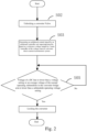
- Fig. 2 is a flowchart of a discharge method for a voltage sourced converter direct-current transmission line provided by an embodiment of the application.
- an additional control signal is generated from an additional controller and superimposed on a reference voltage output by a main controller of the voltage sourced converter direct-current transmission system, so that the converter valve generates a harmonic current in a three-phase bridge arm of the converter, thus accelerating the process of the discharging in the direct-current line through the equivalent resistance and reactance in the converter.
- Fig. 3 is a flowchart of another discharge method for a voltage sourced converter direct-current transmission line provided by an embodiment of the application.
- an additional control signal is generated from an additional controller and superimposed on a reference voltage output by a main controller of the voltage sourced converter direct-current transmission system, so that the converter valve generates a harmonic current in a three-phase bridge arm of a converter, thus accelerating the discharging in the direct-current line through the equivalent resistance and reactance in the converter.
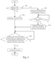
- Fig. 4 is a flowchart of yet another discharge method for a voltage sourced converter direct-current transmission line provided by an embodiment of the application.
- the converter After the residual voltage of the direct-current line is reduced below a specified value or the average voltage of the modules in a normal operating state in the bridge arm is reduced to a specified value, the converter is locked. Then the whole discharge process is ended.
- Fig. 5 is a flowchart of still another discharge method for a voltage sourced converter direct-current transmission line provided by an embodiment of the application.
- an additional control signal is generated from an additional controller and superimposed on a reference voltage output by a main controller of the voltage sourced converter direct-current transmission system, so that the converter valve generates a harmonic current in a three-phase bridge arm of the converter, thus accelerating the process of dissipating the accumulated charges in the direct-current line through the equivalent resistance and reactance in the converter.
- the converter After the residual voltage of the direct-current line is reduced below a specified value or the average voltage of the modules in a normal operating state in the bridge arm is reduced to a specified value, the converter is locked. Then the whole discharge process is ended.
- Fig. 6 is a diagram of an additional controller provided by an embodiment of the application.
- the additional controller C01 comprises an input signal generator C02, a first PI control module C04 and a second PI control module C05, a dq transformation module C03, and a dq inverse transformation module C06.
- the input signal generator C02 generates three-phase negative sequence currents i a , i b , i c , and the amplitude I thereof is an amplitude of a harmonic current injected into the converter, which is p1% of a rated bridge arm current, where p1 is 0.001-100 and can be set according to an actual DC transmission line voltage; a phase ⁇ t is based on a valve side voltage U v or a grid side voltage U s ; n is an integer and n ⁇ 2; ⁇ is a compensation angle, 0° ⁇ 90°.
- the three-phase negative sequence currents i a , i b and i c generate current reference components i fnd ⁇ and i fnq ⁇ through the dq transformation module C03, and difference components generated by comparing current reference components i fnd ⁇ and i fnq ⁇ with dq components i fnd and i fnq of a measured three-phase current signal are input into the first PI control module C04 and the second PI control module C05 to obtain i d 1 and i q 1 .
- u cird k p i fnd * ⁇ i fnd + k i ⁇ 0 t i fnd * ⁇ i fnd + n ⁇ Li fnq
- u cirq k p i fnq * ⁇ i fnq + k i ⁇ 0 t i fnq * ⁇ i fnq ⁇ n ⁇ Li fnd
- the additional control signals u cira , u cirb and u circ of the additional controller are obtained through dq inverse transformation.
- the additional control signals u cira , u cirb and u circ output by the additional controller are superimposed on voltage control signals u refa , u refb and u refc output by a main controller B01 of the voltage sourced converter direct-current transmission system as converter valve control signals, so that the converter valve generates a harmonic current in a three-phase bridge arm of the converter.
- the converter valve generates a harmonic current 5 in the three-phase bridge arm of the converter valve.
- the additional controller When the voltage sourced converter direct-current transmission system is in normal operation, the additional controller is not activated. The additional controller is put into operation when the system is shut down and accelerated discharge is required.
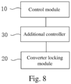
- Fig. 8 is a functional block diagram of a discharge device for a voltage sourced converter direct-current transmission line provided by an embodiment of the application, comprising a control module 10, a converter locking module 20, and an additional controller 30.
- the control module 10 unlocks a converter valve by using a residual voltage of a direct-current line.
- the additional controller 30 generates an additional control signal and superimposes the additional control signal on a reference voltage output by a main controller of the voltage sourced converter direct-current transmission system so that the converter valve generates a harmonic current in a three-phase bridge arm of a converter.
- the converter locking module 20 locks the converter when a direct-current transmission line voltage is lower than a voltage setting or an average voltage of normal operating submodules in the bridge arm of the converter is lower than a submodule operating voltage setting.
- control module 10 charges the converter by using a residual voltage of the direct-current line; determines whether the charging can be completed; unlocks the converter valve if yes; closes an AC incoming switch and charges the converter if not, determines again whether the charging can be completed; and opens the AC incoming switch and unlocks the converter valve at the same time if the charging can be completed.
- the additional controller 30 may comprise an input signal generator, a transformation module, a first PI control module, a second PI control module and an inverse transformation module.
- the input signal generator generates three-phase negative sequence currents; the transformation module transforms the three-phase negative sequence currents into a first current reference component and a second current reference component; the first PI control module receives a first difference component generated by comparing the first current reference component with a measured three-phase current signal, and outputs a first current difference component; the second PI control module receives a second difference component generated by comparing the second current reference component with a measured three-phase current signal, and outputs a second current difference component; and the inverse transformation module receives the first current difference component and the second current difference component, and outputs the additional control signal.
- the above-mentioned device embodiments are only schematic.
- the division of units/modules described in the above embodiments is only a logical function division, and there may be another division mode in actual implementation.
- multiple units, modules, or components may be combined, or integrated into another system, or some features may be omitted or not performed.
- the integrated units/modules are implemented in the form of a software module and sold or used as an independent product, it can be stored in a computer-readable memory.
- the memory includes a USB flash drive, Read-Only Memory (ROM), Random Access Memory (RAM), removable hard disk, magnetic disk or optical disk, and other media that can store program codes.
Landscapes
- Engineering & Computer Science (AREA)
- Power Engineering (AREA)
- Charge And Discharge Circuits For Batteries Or The Like (AREA)
- Rectifiers (AREA)
Abstract
Description
- The application relates to the technical field of power system transmission, in particular to a voltage sourced converter direct-current transmission line discharge method and device, and storage medium.
- As the most controllable transmission method at present, voltage sourced converter direct-current transmission is widely used in occasions like new energy grid connection, island power supply, and offshore platform power supply, and is also a superior solution for grid interconnection and load center power supply in urbans.
- In many occasions, a cable is used as a transmission medium in voltage sourced converter direct-current transmission. A long cable has a large equivalent capacitance and will store energy while direct current passing through, it takes up to 30 to 60 minutes for the electricity accumulated on the cable to be released after voltage sourced converter direct-current transmission is out of operation, and the high voltage before discharge ends is dangerous to personal safety. This problem is particularly prominent in the fields of offshore platform power supply and offshore wind power grid connection. Offshore platforms, especially offshore oil and gas field platforms, have many devices and are extremely sensitive to heat and fire sources. When a voltage sourced converter direct-current transmission system is out of service, it is necessary to enter a valve hall timely to check whether there are any dangerous sources, so as to ensure the safety of the whole platform. However, due to the limitation of cable discharge time, people often have to wait for more than half an hour to approach the valve hall, which poses a serious safety threat.
- At present, there are two methods to accelerate the discharge speed of voltage sourced converter direct-current transmission cables. The first method is to add a breaker and a resistance grounding circuit to two ends of the cable to speed up discharge, that is, adding additional complex equipment in order to realize safe and fast discharge. The second method is to accelerate discharging by means of a direct-current energy-consuming device, which cannot be realized in a system in which no energy-consuming device is designed or installed. Take offshore voltage sourced converter direct-current transmission as an example, core equipment is assembled in a dock and high-pressure testing is completed, and huge energy-consuming devices are generally not included, which leads to doubling of the test time and a significant increase in the engineering cost.
- An embodiment of the application provides a discharge method for a voltage sourced converter direct-current transmission line. The method comprises: unlocking a converter valve; generating an additional control signal by an additional controller and superimposing the additional control signal on a reference voltage output by a main controller of the voltage sourced converter direct-current transmission system, so that the converter valve generates a harmonic current in a three-phase bridge arm of a converter; and locking the converter when a direct-current transmission line voltage is lower than a voltage setting or an average voltage of normal operating submodules in the converter bridge arm is lower than a submodule operating voltage setting.
- According to some embodiments, before unlocking the converter, the method further comprises: charging the converter by using a residual voltage of the direct-current line, determining whether the charging can be completed, and unlocking the converter valve if yes; wherein after unlocking the converter, the method further comprises: if the charging cannot be completed, closing an AC incoming switch, charging the converter, and determining again whether the charging can be completed; and if the charging can be completed, opening the AC incoming switch and unlocking the converter valve at a same time.
- According to some embodiments, the additional controller comprises an input signal generator, a first PI control module, a second PI control module, a transformation module and an inverse transformation module, wherein the input signal generator is configured to generate three-phase negative sequence currents; the transformation module is configured to transform the three-phase negative sequence currents into a first current reference component and a second current reference component; the first PI control module is configured to receive a first difference component generated by comparing the first current reference component with a measured three-phase current signal, and output a first current difference component; the second PI control module is configured to receive a second difference component generated by comparing the second current reference component with the measured three-phase current signal, and output a second current difference component; and the inverse transformation module is configured to receive the first current difference component and the second current difference component, and output the additional control signal.
- According to some embodiments, the input signal generator generates three-phase negative sequence currents ia, ib, ic, the amplitude I thereof is an amplitude of a harmonic current injected into the converter, which is p1% of a rated bridge arm current, where p1 is 0.001-100 and can be set according to an actual DC transmission line voltage; a phase ωt is based on a valve side voltage Uv or a grid side voltage Us; n is an integer and n≥2; δ is a compensation angle, 0°≤δ≤90°; and


- According to some embodiments, the additional control signals ucira , ucirb and ucirc output by the additional controller are correspondingly superimposed on voltage control signals urefa , urefb and urefc output by a main controller of the voltage sourced converter direct-current transmission system to serve as converter valve control signals, so that the converter valve generates the harmonic current in the three-phase bridge arm.
- According to some embodiments, during normal operation, the additional controller don't work and is activated when discharging is required.
- An embodiment of the application provides a discharge device for a voltage sourced converter direct-current transmission line, comprising a control module, an additional controller and a converter locking module, wherein the control module is configured to unlock a converter valve; the additional controller is configured to generate an additional control signal and superimpose the additional control signal on a reference voltage output by a main controller of the voltage sourced converter direct-current transmission system, so that the converter valve generates a harmonic current in a three-phase bridge arm of a converter; and the converter locking module is configured to lock the converter when a voltage of a direct-current line is lower than a voltage setting or an average voltage of normal operating sub-modules in the bridge arm is lower than the sub-module operating voltage setting.
- According to some embodiments, the control module is configured to charge the converter by using a residual voltage of the direct-current line, determines whether the charging can be completed, unlocks the converter valve if yes, closes an AC incoming switch and charges the converter if not, determines again whether the charging can be completed, and opens the AC incoming switch and unlocks the converter valve at the same time if the charging can be completed.
- According to some embodiments, the additional controller comprises an input signal generator, a transformation module, a first PI control module, a second PI control module and an inverse transformation module, wherein the input signal generator generates three-phase negative sequence currents; the transformation module transforms the three-phase negative sequence currents into a first current reference component and a second current reference component; the first PI control module receives a first difference component generated by comparing the first current reference component with a measured three-phase current signal, and outputs a first current difference component; the second PI control module receives a second difference component generated by comparing the second current reference component with the measured three-phase current signal, and outputs a second current difference component; and the inverse transformation module receives the first current difference component and the second current difference component, and outputs the additional control signal.
- According to some embodiments, the application further provides a computer-readable storage medium on which a processor program is stored, wherein the processor program is used to execute the method as mentioned above.
- According to the technical scheme provided by the embodiments of the application, the fast discharge method for the voltage sourced converter direct-current transmission cable does not need any additional equipment, so the economical performance is good. Further, the method is controllable in discharge time and excellent in flexibility, and can be used reliably in any situation, thus having great adaptability.
- In order to explain the technical solution in the embodiments of the application more clearly, the drawings used in the description of the embodiments will be briefly introduced below. Obviously, the drawings in the following description only illustrate some embodiments of the application, and for those of ordinary technicians in the field, other drawings can be obtained according to these drawings without paying creative effort.
-
Fig. 1 is a circuit diagram of a discharge method for a voltage sourced converter direct-current transmission line provided by an embodiment of the application. -
Fig. 2 is a flowchart of a discharge method for a voltage sourced converter direct-current transmission line provided by an embodiment of the application. -
Fig. 3 is a flowchart of another discharge method for a voltage sourced converter direct-current transmission line provided by an embodiment of the application. -
Fig. 4 is a flowchart of yet another discharge method for a voltage sourced converter direct-current transmission line provided by an embodiment of the application. -
Fig. 5 is a flowchart of still another discharge method for a voltage sourced converter direct-current transmission line provided by an embodiment of the application. -
Fig. 6 is a diagram of an additional controller provided by an embodiment of the application. -
Fig. 7 is a diagram of an additional control signal provided by an embodiment of the application. -
Fig. 8 is a functional block diagram of a discharge device for a voltage sourced converter direct-current transmission line provided by an embodiment of the application. - The technical solution in the embodiments of the application will be described clearly and completely with reference to the drawings in the embodiments of the application. Obviously, the described embodiments are part of the embodiments of the application, not all of them. Based on the embodiments in the application, all other embodiments obtained by those skilled in the art without creative effort are within the scope of the application.
- It should be understood that the terms "first" and "second" in the claims, specification and drawings of the application are used to distinguish different objects, but not to describe a specific order. As used in the specification and claims of the application, the terms "comprise" and "include" indicate the presence of the described features, integers, steps, operations, elements and/or components, but do not exclude the presence or addition of one or more other features, integers, steps, operations, elements, components and/or groups thereof.
-
Fig. 1 is a circuit diagram of a discharge method for a voltage sourced converter direct-current transmission line provided by an embodiment of the application. - A
converter 3 is controlled to turn on, so that a direct-current line 1 and a direct-current line 7 form a circuit through theconverter valve 3, and accumulated charges in the direct-current line are dissipated through equivalent resistance and reactance in theconverter 3, thus realizing rapid discharge of the direct-current line. -
Fig. 2 is a flowchart of a discharge method for a voltage sourced converter direct-current transmission line provided by an embodiment of the application. - In S02, a converter valve is unlocked.
- When the converter valve is unlocked, accumulated charges in direct-current line are dissipated through equivalent resistance and reactance in the converter.
- In S03, an additional control signal is generated from an additional controller and superimposed on a reference voltage output by a main controller of the voltage sourced converter direct-current transmission system, so that the converter valve generates a harmonic current in a three-phase bridge arm of the converter, thus accelerating the process of the discharging in the direct-current line through the equivalent resistance and reactance in the converter.
- In S05, when a voltage of the direct-current line is lower than a voltage setting or an average voltage of normal operating submodules in the bridge arm of converter is lower than a submodule operating voltage setting, the converter is locked, thereby finishing the whole accelerated discharge process.
-
Fig. 3 is a flowchart of another discharge method for a voltage sourced converter direct-current transmission line provided by an embodiment of the application. - In S01, when a voltage sourced converter direct-current transmission system is shut down and an AC incoming switch is opened, whether a voltage of a sub-module is higher than an unlocking threshold and meets the unlocking conditions is determined, and the control process is ended if not.
- In S02, a converter valve is unlocked.
- In S031, after the converter valve is unlocked, an additional control signal is generated from an additional controller and superimposed on a reference voltage output by a main controller of the voltage sourced converter direct-current transmission system, so that the converter valve generates a harmonic current in a three-phase bridge arm of a converter, thus accelerating the discharging in the direct-current line through the equivalent resistance and reactance in the converter.
- In S05, when a voltage of the direct-current line is lower than a voltage setting or an average voltage of normal operating submodules in the bridge arm of the converter is lower than a submodule operating voltage setting, the converter is locked, thereby finishing the whole discharge process accelerated.
-
Fig. 4 is a flowchart of yet another discharge method for a voltage sourced converter direct-current transmission line provided by an embodiment of the application. - In S01, after a voltage sourced converter direct-current transmission system is shut down and the AC incoming switch is opened, a converter is charged by using a residual voltage of a direct-current line, and whether the charging can be completed is determined.
- In S02, if the charging can be completed, the converter valve is unlocked.
- In S03, if the charging cannot be completed, the AC incoming switch is closed, the converter is charged, and whether the charging can be completed is determined again.
- In S04, if the charging can be completed, the AC incoming switch is opened and the converter valve is unlocked.
- When the converter valve is unlocked, accumulated charges in a direct-current line are dissipated through equivalent resistance and reactance in the converter.
- In S05, when a voltage of the direct-current line is lower than a voltage setting or an average voltage of normal operating submodules in the bridge arm of the converter is lower than a submodule operating voltage setting, the converter is locked.
- After the residual voltage of the direct-current line is reduced below a specified value or the average voltage of the modules in a normal operating state in the bridge arm is reduced to a specified value, the converter is locked. Then the whole discharge process is ended.
-
Fig. 5 is a flowchart of still another discharge method for a voltage sourced converter direct-current transmission line provided by an embodiment of the application. - In S01, after a voltage sourced converter direct-current transmission system is shut down and the AC incoming switch is opened, a converter is charged by using a residual voltage of a direct-current line, and whether the charging can be completed is determined.
- In S02, if the charging can be completed, the converter valve is unlocked.
- In S03, if the charging cannot be completed, the AC incoming switch is closed, the converter is charged, and whether the charging can be completed is determined again.
- In S04, if the charging can be completed, the AC incoming switch is opened and the converter valve is unlocked.
- In S041, after the converter valve is unlocked, an additional control signal is generated from an additional controller and superimposed on a reference voltage output by a main controller of the voltage sourced converter direct-current transmission system, so that the converter valve generates a harmonic current in a three-phase bridge arm of the converter, thus accelerating the process of dissipating the accumulated charges in the direct-current line through the equivalent resistance and reactance in the converter.
- In S05, when a voltage of the direct-current line is lower than a voltage setting or an average voltage of normal operating submodules in the bridge arm of the converter is lower than a submodule operating voltage setting, the converter is locked.
- After the residual voltage of the direct-current line is reduced below a specified value or the average voltage of the modules in a normal operating state in the bridge arm is reduced to a specified value, the converter is locked. Then the whole discharge process is ended.
-
Fig. 6 is a diagram of an additional controller provided by an embodiment of the application. - As shown in
Fig. 6 , the additional controller C01 comprises an input signal generator C02, a first PI control module C04 and a second PI control module C05, a dq transformation module C03, and a dq inverse transformation module C06. - The input signal generator C02 generates three-phase negative sequence currents ia, ib, ic, and the amplitude I thereof is an amplitude of a harmonic current injected into the converter, which is p1% of a rated bridge arm current, where p1 is 0.001-100 and can be set according to an actual DC transmission line voltage; a phase ωt is based on a valve side voltage Uv or a grid side voltage Us; n is an integer and n≥2; δ is a compensation angle, 0°≤δ≤90°.


- The three-phase negative sequence currents ia, ib and ic generate current reference components


- The dq axis components of the additional control signal of the additional controller are: ucird and ucirq :


- In C06, the additional control signals ucira, ucirb and ucirc of the additional controller are obtained through dq inverse transformation.
- As shown in
Fig. 7 , in one possible implementation of the method, the additional control signals ucira , ucirb and ucirc output by the additional controller are superimposed on voltage control signals urefa, urefb and urefc output by a main controller B01 of the voltage sourced converter direct-current transmission system as converter valve control signals, so that the converter valve generates a harmonic current in a three-phase bridge arm of the converter. As shown inFig. 1 , the converter valve generates a harmonic current 5 in the three-phase bridge arm of the converter valve. - When the voltage sourced converter direct-current transmission system is in normal operation, the additional controller is not activated. The additional controller is put into operation when the system is shut down and accelerated discharge is required.
-
Fig. 8 is a functional block diagram of a discharge device for a voltage sourced converter direct-current transmission line provided by an embodiment of the application, comprising acontrol module 10, aconverter locking module 20, and anadditional controller 30. - The
control module 10 unlocks a converter valve by using a residual voltage of a direct-current line. - The
additional controller 30 generates an additional control signal and superimposes the additional control signal on a reference voltage output by a main controller of the voltage sourced converter direct-current transmission system so that the converter valve generates a harmonic current in a three-phase bridge arm of a converter. - The
converter locking module 20 locks the converter when a direct-current transmission line voltage is lower than a voltage setting or an average voltage of normal operating submodules in the bridge arm of the converter is lower than a submodule operating voltage setting. - Optionally, the
control module 10 charges the converter by using a residual voltage of the direct-current line; determines whether the charging can be completed; unlocks the converter valve if yes; closes an AC incoming switch and charges the converter if not, determines again whether the charging can be completed; and opens the AC incoming switch and unlocks the converter valve at the same time if the charging can be completed. - The
additional controller 30 may comprise an input signal generator, a transformation module, a first PI control module, a second PI control module and an inverse transformation module. - The input signal generator generates three-phase negative sequence currents; the transformation module transforms the three-phase negative sequence currents into a first current reference component and a second current reference component; the first PI control module receives a first difference component generated by comparing the first current reference component with a measured three-phase current signal, and outputs a first current difference component; the second PI control module receives a second difference component generated by comparing the second current reference component with a measured three-phase current signal, and outputs a second current difference component; and the inverse transformation module receives the first current difference component and the second current difference component, and outputs the additional control signal.
- It should be understood that the above-mentioned device embodiments are only schematic. For example, the division of units/modules described in the above embodiments is only a logical function division, and there may be another division mode in actual implementation. For example, multiple units, modules, or components may be combined, or integrated into another system, or some features may be omitted or not performed. If the integrated units/modules are implemented in the form of a software module and sold or used as an independent product, it can be stored in a computer-readable memory. The memory includes a USB flash drive, Read-Only Memory (ROM), Random Access Memory (RAM), removable hard disk, magnetic disk or optical disk, and other media that can store program codes.
- The embodiments of the application have been introduced in detail above. Specific examples are applied herein to illustrate the principle and implementation of the application. The above embodiments are only used to help understand the method of the application and its core ideas. The changes or deformations made by those skilled in the art based on the ideas of the application and the specific implementation and application scope of the application are within the scope of the application. To sum up, the content of this specification should not be understood as a limitation of the application.
Claims (10)
- A discharge method for a voltage sourced converter direct-current transmission line, comprising:unlocking a converter valve;generating an additional control signal by an additional controller and superimposing the additional control signal on a reference voltage output by a main controller of a voltage sourced converter direct-current transmission system, so that the converter valve generates a harmonic current in a three-phase bridge arm of a converter; andlocking the converter when a direct-current transmission line voltage is lower than a voltage setting or an average voltage of normal operating submodules in the bridge arm of the converter is lower than a submodule operating voltage setting.
- The method according to claim 1, wherein before unlocking the converter, the method further comprises:charging the converter by using a residual voltage of the direct-current line, determining whether the charging can be completed, and unlocking the converter valve if yes;wherein after unlocking the converter, the method further comprises:if the charging cannot be completed, closing an AC incoming switch, charging the converter, and determining again whether the charging can be completed; andif the charging can be completed, opening the AC incoming switch and unlocking the converter valve at a same time.
- The method according to claim 1 or 2, wherein the additional controller comprises:an input signal generator configured to generate three-phase negative sequence currents;a transformation module configured to transform the three-phase negative sequence currents into a first current reference component and a second current reference component;a first PI control module configured to receive a first difference component generated by comparing the first current reference component with a measured three-phase current signal, and output a first current difference component;a second PI control module configured to receive a second difference component generated by comparing the second current reference component with the measured three-phase current signal, and output a second current difference component; andan inverse transformation module configured to receive the first current difference component and the second current difference component, and output the additional control signal.
- The method according to claim 3, wherein the input signal generator generates three-phase negative sequence currents ia, ib, ic, the amplitude I thereof is an amplitude of a harmonic current injected into the converter, which is p1% of a rated bridge arm current, where p1 is 0.001-100 and can be set according to an actual DC transmission line voltage; a phase ωt is based on a valve side voltage Uv or a grid side voltage Us; n is an integer and n ≥ 2; δ is a compensation angle, 0° ≤ δ ≤ 90°; and


- The method according to claim 3, wherein the additional control signals ucira, ucirb and ucirc output by the additional controller are correspondingly superimposed on voltage control signals urefa , urefb and urefc output by the main controller of the voltage sourced converter direct-current transmission system to serve as converter valve control signals, so that the converter valve generates the harmonic current in the three-phase bridge arm.
- The method according to claim 1 or 2, wherein during normal operation, the additional controller exits, and is put back in when discharging is required.
- A discharge device for a voltage sourced converter direct-current transmission line, comprising:a control module configured to unlock a converter valve;an additional controller configured to generate an additional control signal and superimpose the additional control signal on a reference voltage output by a voltage sourced converter direct-current transmission main controller, so that the converter valve generates a harmonic current in a three-phase bridge arm of a converter; anda converter locking module configured to lock the converter when a direct-current transmission line voltage is lower than a voltage setting or an average voltage of normal operating submodules in the bridge arm of the converter is lower than a submodule operating voltage setting.
- The device according to claim 7, wherein the control module is configured to charge the converter by using a residual voltage of the direct-current line, determine whether the charging can be completed, unlock the converter valve if yes, close an AC incoming switch and charge the converter if not, determine again whether the charging can be completed, and open the AC incoming switch and unlock the converter valve at a same time if the charging can be completed.
- The device according to claim 7 or 8, wherein the additional controller comprises:an input signal generator configured to generate three-phase negative sequence currents;a transformation module configured to transform the three-phase negative sequence currents into a first current reference component and a second current reference component;a first PI control module configured to receive a first difference component generated by comparing the first current reference component with a measured three-phase current signal, and output a first current difference component;a second PI control module configured to receive a second difference component generated by comparing the second current reference component with the measured three-phase current signal, and output a second current difference component; andan inverse transformation module configured to receive the first current difference component and the second current difference component, and output the additional control signal.
- A computer-readable storage medium on which a processor program is stored, wherein the processor program is used to execute the method according to any one of claims 1-6.
Applications Claiming Priority (2)
| Application Number | Priority Date | Filing Date | Title |
|---|---|---|---|
| CN202010949386.6A CN112086993B (en) | 2020-09-10 | 2020-09-10 | Flexible direct-current transmission line discharging method and device and storage medium |
| PCT/CN2021/117724 WO2022053020A1 (en) | 2020-09-10 | 2021-09-10 | Flexible direct-current transmission line discharging method and apparatus, and storage medium |
Publications (3)
| Publication Number | Publication Date |
|---|---|
| EP4184742A1 true EP4184742A1 (en) | 2023-05-24 |
| EP4184742A4 EP4184742A4 (en) | 2024-08-28 |
| EP4184742B1 EP4184742B1 (en) | 2025-05-21 |
Family
ID=73737029
Family Applications (1)
| Application Number | Title | Priority Date | Filing Date |
|---|---|---|---|
| EP21866072.8A Active EP4184742B1 (en) | 2020-09-10 | 2021-09-10 | Flexible direct-current transmission line discharging method and apparatus, and storage medium |
Country Status (3)
| Country | Link |
|---|---|
| EP (1) | EP4184742B1 (en) |
| CN (1) | CN112086993B (en) |
| WO (1) | WO2022053020A1 (en) |
Families Citing this family (4)
| Publication number | Priority date | Publication date | Assignee | Title |
|---|---|---|---|---|
| CN112086993B (en) * | 2020-09-10 | 2022-01-14 | 南京南瑞继保电气有限公司 | Flexible direct-current transmission line discharging method and device and storage medium |
| CN114006523B (en) * | 2021-09-28 | 2023-12-29 | 中国三峡建工(集团)有限公司 | A discharge inspection device and method for a flexible DC converter valve power module |
| JP2025525021A (en) * | 2022-07-26 | 2025-08-01 | イオントラ インコーポレイテッド | Smart Battery |
| KR20260041150A (en) * | 2023-09-19 | 2026-03-26 | 컨템포러리 엠퍼렉스 퓨쳐 에너지 리서치 인스티튜트 (상하이) 리미티드 | High-voltage series-connected energy storage system, control method and control device for a storage device |
Family Cites Families (9)
| Publication number | Priority date | Publication date | Assignee | Title |
|---|---|---|---|---|
| CN103308869B (en) * | 2013-07-15 | 2015-11-25 | 国家电网公司 | Modular multi-level multi-terminal flexible direct-current transmission system starting characteristics test method |
| CN105811751B (en) * | 2014-12-29 | 2018-08-14 | 国家电网公司 | A kind of unlock startup control method of flexible direct-current transmission converter |
| CN106505512B (en) * | 2016-12-07 | 2019-01-08 | 北京四方继保自动化股份有限公司 | Number is unlocked after soft straight control system temporary blocking again to overflow trip method |
| CN106877298B (en) * | 2017-03-27 | 2018-09-21 | 上海交通大学 | MMC-HVDC system dc line protection methods |
| CN107196539B (en) * | 2017-06-23 | 2019-10-11 | 西安交通大学 | A zero-DC voltage fault ride-through control method for MMC in the state of bridge arm parameter asymmetry |
| CN108400701A (en) * | 2018-04-24 | 2018-08-14 | 国网冀北电力有限公司电力科学研究院 | A kind of flexible direct current power transmission system |
| CN109755954B (en) * | 2019-03-26 | 2022-07-22 | 南京南瑞继保电气有限公司 | Fault protection method and device for current converter of hybrid direct-current power transmission system |
| CN111555334A (en) * | 2020-04-15 | 2020-08-18 | 南京南瑞继保电气有限公司 | Active discharge method, control device and electronic equipment for high-voltage DC cable |
| CN112086993B (en) * | 2020-09-10 | 2022-01-14 | 南京南瑞继保电气有限公司 | Flexible direct-current transmission line discharging method and device and storage medium |
-
2020
- 2020-09-10 CN CN202010949386.6A patent/CN112086993B/en active Active
-
2021
- 2021-09-10 WO PCT/CN2021/117724 patent/WO2022053020A1/en not_active Ceased
- 2021-09-10 EP EP21866072.8A patent/EP4184742B1/en active Active
Also Published As
| Publication number | Publication date |
|---|---|
| WO2022053020A1 (en) | 2022-03-17 |
| EP4184742A4 (en) | 2024-08-28 |
| EP4184742B1 (en) | 2025-05-21 |
| CN112086993A (en) | 2020-12-15 |
| CN112086993B (en) | 2022-01-14 |
Similar Documents
| Publication | Publication Date | Title |
|---|---|---|
| EP4184742B1 (en) | Flexible direct-current transmission line discharging method and apparatus, and storage medium | |
| CN104300569B (en) | HVDC dc-side short-circuit fault based on mixed type MMC passes through and restoration methods | |
| US6400585B2 (en) | Method and control system for voltage control at a converter station | |
| US7456695B2 (en) | Apparatus, method and computer program product for tracking information in an electric grid | |
| US12074535B2 (en) | Control device and power conversion device | |
| Liu et al. | Extinction angle predictive control strategy for commutation failure mitigation in HVDC systems considering voltage distortion | |
| EP4412023A1 (en) | Power conversion device and power conversion system | |
| EP3145070A1 (en) | Control method and device for three-phase uninterruptible power supply, and three-phase uninterruptible power supply | |
| Zhan et al. | Dynamic voltage restorer with battery energy storage for voltage dip mitigation | |
| Hoevenaars et al. | New marine harmonic standards | |
| US12068610B2 (en) | Control device | |
| KR20220017567A (en) | Method for controlling fault using switching technique of three phase four wire interlinking converter | |
| Carbone et al. | Sensorless control of medium voltage induction motor with LC filter and long cable in oil pump applications | |
| EP4318918A1 (en) | Power conversion device and control device | |
| Evans et al. | Meeting harmonic limits on marine vessels | |
| WO2018124561A2 (en) | Method for removing direct current component at output terminal of mmc converter | |
| US12218577B2 (en) | Power conversion device and control device having overcurrent suppression | |
| KR102415863B1 (en) | Temporary Fault Ride-Through Method in power distribution system with distributed generations based on power conversion system, and recording medium thereof | |
| CN109155598B (en) | HVDC inverter system, control method thereof, and HVDC system using the same | |
| Luiz et al. | Improving power quality in mining industries with a three-level active front end | |
| US6535404B2 (en) | Controlling operation of an AC/DC converter | |
| Mohanty et al. | Protection of converter dominated MV microgrid using changes in current's phase angle | |
| Majumder et al. | Performance analysis of a micro grid VSI under asymmetric conditions | |
| Vicenzutti et al. | Simplified analytical modeling and experimental validation of diode bridge rectifier operation during rail-to-rail short-circuit faults in synchronous generator-fed DC distribution systems | |
| Farbis et al. | Marine duty harmonic mitigation on dc propulsion saves oil service vessel program |
Legal Events
| Date | Code | Title | Description |
|---|---|---|---|
| STAA | Information on the status of an ep patent application or granted ep patent |
Free format text: STATUS: THE INTERNATIONAL PUBLICATION HAS BEEN MADE |
|
| PUAI | Public reference made under article 153(3) epc to a published international application that has entered the european phase |
Free format text: ORIGINAL CODE: 0009012 |
|
| STAA | Information on the status of an ep patent application or granted ep patent |
Free format text: STATUS: REQUEST FOR EXAMINATION WAS MADE |
|
| 17P | Request for examination filed |
Effective date: 20230215 |
|
| AK | Designated contracting states |
Kind code of ref document: A1 Designated state(s): AL AT BE BG CH CY CZ DE DK EE ES FI FR GB GR HR HU IE IS IT LI LT LU LV MC MK MT NL NO PL PT RO RS SE SI SK SM TR |
|
| DAV | Request for validation of the european patent (deleted) | ||
| DAX | Request for extension of the european patent (deleted) | ||
| A4 | Supplementary search report drawn up and despatched |
Effective date: 20240729 |
|
| RIC1 | Information provided on ipc code assigned before grant |
Ipc: H02M 7/483 20070101ALI20240723BHEP Ipc: H02M 1/32 20070101ALI20240723BHEP Ipc: H02J 3/36 20060101AFI20240723BHEP |
|
| GRAP | Despatch of communication of intention to grant a patent |
Free format text: ORIGINAL CODE: EPIDOSNIGR1 |
|
| STAA | Information on the status of an ep patent application or granted ep patent |
Free format text: STATUS: GRANT OF PATENT IS INTENDED |
|
| RIC1 | Information provided on ipc code assigned before grant |
Ipc: H02M 7/483 20070101ALI20250130BHEP Ipc: H02M 1/32 20070101ALI20250130BHEP Ipc: H02J 3/36 20060101AFI20250130BHEP |
|
| INTG | Intention to grant announced |
Effective date: 20250221 |
|
| GRAS | Grant fee paid |
Free format text: ORIGINAL CODE: EPIDOSNIGR3 |
|
| GRAA | (expected) grant |
Free format text: ORIGINAL CODE: 0009210 |
|
| STAA | Information on the status of an ep patent application or granted ep patent |
Free format text: STATUS: THE PATENT HAS BEEN GRANTED |
|
| AK | Designated contracting states |
Kind code of ref document: B1 Designated state(s): AL AT BE BG CH CY CZ DE DK EE ES FI FR GB GR HR HU IE IS IT LI LT LU LV MC MK MT NL NO PL PT RO RS SE SI SK SM TR |
|
| REG | Reference to a national code |
Ref country code: GB Ref legal event code: FG4D |
|
| REG | Reference to a national code |
Ref country code: CH Ref legal event code: EP |
|
| REG | Reference to a national code |
Ref country code: DE Ref legal event code: R096 Ref document number: 602021031265 Country of ref document: DE |
|
| REG | Reference to a national code |
Ref country code: IE Ref legal event code: FG4D |
|
| REG | Reference to a national code |
Ref country code: NL Ref legal event code: FP |
|
| P01 | Opt-out of the competence of the unified patent court (upc) registered |
Free format text: CASE NUMBER: APP_27335/2025 Effective date: 20250610 |
|
| PG25 | Lapsed in a contracting state [announced via postgrant information from national office to epo] |
Ref country code: FI Free format text: LAPSE BECAUSE OF FAILURE TO SUBMIT A TRANSLATION OF THE DESCRIPTION OR TO PAY THE FEE WITHIN THE PRESCRIBED TIME-LIMIT Effective date: 20250521 Ref country code: ES Free format text: LAPSE BECAUSE OF FAILURE TO SUBMIT A TRANSLATION OF THE DESCRIPTION OR TO PAY THE FEE WITHIN THE PRESCRIBED TIME-LIMIT Effective date: 20250521 Ref country code: PT Free format text: LAPSE BECAUSE OF FAILURE TO SUBMIT A TRANSLATION OF THE DESCRIPTION OR TO PAY THE FEE WITHIN THE PRESCRIBED TIME-LIMIT Effective date: 20250922 |
|
| REG | Reference to a national code |
Ref country code: LT Ref legal event code: MG9D |
|
| PG25 | Lapsed in a contracting state [announced via postgrant information from national office to epo] |
Ref country code: NO Free format text: LAPSE BECAUSE OF FAILURE TO SUBMIT A TRANSLATION OF THE DESCRIPTION OR TO PAY THE FEE WITHIN THE PRESCRIBED TIME-LIMIT Effective date: 20250821 Ref country code: GR Free format text: LAPSE BECAUSE OF FAILURE TO SUBMIT A TRANSLATION OF THE DESCRIPTION OR TO PAY THE FEE WITHIN THE PRESCRIBED TIME-LIMIT Effective date: 20250822 |
|
| PG25 | Lapsed in a contracting state [announced via postgrant information from national office to epo] |
Ref country code: PL Free format text: LAPSE BECAUSE OF FAILURE TO SUBMIT A TRANSLATION OF THE DESCRIPTION OR TO PAY THE FEE WITHIN THE PRESCRIBED TIME-LIMIT Effective date: 20250521 |
|
| PGFP | Annual fee paid to national office [announced via postgrant information from national office to epo] |
Ref country code: NL Payment date: 20250927 Year of fee payment: 5 |
|
| PG25 | Lapsed in a contracting state [announced via postgrant information from national office to epo] |
Ref country code: BG Free format text: LAPSE BECAUSE OF FAILURE TO SUBMIT A TRANSLATION OF THE DESCRIPTION OR TO PAY THE FEE WITHIN THE PRESCRIBED TIME-LIMIT Effective date: 20250521 |
|
| PG25 | Lapsed in a contracting state [announced via postgrant information from national office to epo] |
Ref country code: HR Free format text: LAPSE BECAUSE OF FAILURE TO SUBMIT A TRANSLATION OF THE DESCRIPTION OR TO PAY THE FEE WITHIN THE PRESCRIBED TIME-LIMIT Effective date: 20250521 |
|
| PGFP | Annual fee paid to national office [announced via postgrant information from national office to epo] |
Ref country code: AT Payment date: 20251020 Year of fee payment: 5 |
|
| PG25 | Lapsed in a contracting state [announced via postgrant information from national office to epo] |
Ref country code: RS Free format text: LAPSE BECAUSE OF FAILURE TO SUBMIT A TRANSLATION OF THE DESCRIPTION OR TO PAY THE FEE WITHIN THE PRESCRIBED TIME-LIMIT Effective date: 20250821 |
|
| PG25 | Lapsed in a contracting state [announced via postgrant information from national office to epo] |
Ref country code: IS Free format text: LAPSE BECAUSE OF FAILURE TO SUBMIT A TRANSLATION OF THE DESCRIPTION OR TO PAY THE FEE WITHIN THE PRESCRIBED TIME-LIMIT Effective date: 20250921 |
|
| PG25 | Lapsed in a contracting state [announced via postgrant information from national office to epo] |
Ref country code: LV Free format text: LAPSE BECAUSE OF FAILURE TO SUBMIT A TRANSLATION OF THE DESCRIPTION OR TO PAY THE FEE WITHIN THE PRESCRIBED TIME-LIMIT Effective date: 20250521 |
|
| REG | Reference to a national code |
Ref country code: AT Ref legal event code: MK05 Ref document number: 1797646 Country of ref document: AT Kind code of ref document: T Effective date: 20250521 |
|
| PGFP | Annual fee paid to national office [announced via postgrant information from national office to epo] |
Ref country code: DE Payment date: 20251002 Year of fee payment: 5 |
|
| PG25 | Lapsed in a contracting state [announced via postgrant information from national office to epo] |
Ref country code: AT Free format text: LAPSE BECAUSE OF FAILURE TO SUBMIT A TRANSLATION OF THE DESCRIPTION OR TO PAY THE FEE WITHIN THE PRESCRIBED TIME-LIMIT Effective date: 20250521 Ref country code: SM Free format text: LAPSE BECAUSE OF FAILURE TO SUBMIT A TRANSLATION OF THE DESCRIPTION OR TO PAY THE FEE WITHIN THE PRESCRIBED TIME-LIMIT Effective date: 20250521 Ref country code: DK Free format text: LAPSE BECAUSE OF FAILURE TO SUBMIT A TRANSLATION OF THE DESCRIPTION OR TO PAY THE FEE WITHIN THE PRESCRIBED TIME-LIMIT Effective date: 20250521 |
|
| PG25 | Lapsed in a contracting state [announced via postgrant information from national office to epo] |
Ref country code: CZ Free format text: LAPSE BECAUSE OF FAILURE TO SUBMIT A TRANSLATION OF THE DESCRIPTION OR TO PAY THE FEE WITHIN THE PRESCRIBED TIME-LIMIT Effective date: 20250521 |
|
| PG25 | Lapsed in a contracting state [announced via postgrant information from national office to epo] |
Ref country code: EE Free format text: LAPSE BECAUSE OF FAILURE TO SUBMIT A TRANSLATION OF THE DESCRIPTION OR TO PAY THE FEE WITHIN THE PRESCRIBED TIME-LIMIT Effective date: 20250521 |
|
| PG25 | Lapsed in a contracting state [announced via postgrant information from national office to epo] |
Ref country code: SK Free format text: LAPSE BECAUSE OF FAILURE TO SUBMIT A TRANSLATION OF THE DESCRIPTION OR TO PAY THE FEE WITHIN THE PRESCRIBED TIME-LIMIT Effective date: 20250521 |
|
| PG25 | Lapsed in a contracting state [announced via postgrant information from national office to epo] |
Ref country code: IT Free format text: LAPSE BECAUSE OF FAILURE TO SUBMIT A TRANSLATION OF THE DESCRIPTION OR TO PAY THE FEE WITHIN THE PRESCRIBED TIME-LIMIT Effective date: 20250521 |
|
| REG | Reference to a national code |
Ref country code: DE Ref legal event code: R097 Ref document number: 602021031265 Country of ref document: DE |
|
| PG25 | Lapsed in a contracting state [announced via postgrant information from national office to epo] |
Ref country code: RO Free format text: LAPSE BECAUSE OF FAILURE TO SUBMIT A TRANSLATION OF THE DESCRIPTION OR TO PAY THE FEE WITHIN THE PRESCRIBED TIME-LIMIT Effective date: 20250521 |
|
| PLBE | No opposition filed within time limit |
Free format text: ORIGINAL CODE: 0009261 |
|
| STAA | Information on the status of an ep patent application or granted ep patent |
Free format text: STATUS: NO OPPOSITION FILED WITHIN TIME LIMIT |
|
| REG | Reference to a national code |
Ref country code: CH Ref legal event code: L10 Free format text: ST27 STATUS EVENT CODE: U-0-0-L10-L00 (AS PROVIDED BY THE NATIONAL OFFICE) Effective date: 20260402 |
|
| 26N | No opposition filed |
Effective date: 20260224 |
|
| REG | Reference to a national code |
Ref country code: CH Ref legal event code: H13 Free format text: ST27 STATUS EVENT CODE: U-0-0-H10-H13 (AS PROVIDED BY THE NATIONAL OFFICE) Effective date: 20260504 |