EP4184724A1 - Connector frame, terminal connector frame, terminal connector and connector assembly - Google Patents
Connector frame, terminal connector frame, terminal connector and connector assembly Download PDFInfo
- Publication number
- EP4184724A1 EP4184724A1 EP21208779.5A EP21208779A EP4184724A1 EP 4184724 A1 EP4184724 A1 EP 4184724A1 EP 21208779 A EP21208779 A EP 21208779A EP 4184724 A1 EP4184724 A1 EP 4184724A1
- Authority
- EP
- European Patent Office
- Prior art keywords
- connector
- terminal
- frame
- connector frame
- electric
- Prior art date
- Legal status (The legal status is an assumption and is not a legal conclusion. Google has not performed a legal analysis and makes no representation as to the accuracy of the status listed.)
- Pending
Links
Images

Classifications
-
- H—ELECTRICITY
- H01—ELECTRIC ELEMENTS
- H01R—ELECTRICALLY-CONDUCTIVE CONNECTIONS; STRUCTURAL ASSOCIATIONS OF A PLURALITY OF MUTUALLY-INSULATED ELECTRICAL CONNECTING ELEMENTS; COUPLING DEVICES; CURRENT COLLECTORS
- H01R13/00—Details of coupling devices of the kinds covered by groups H01R12/70 or H01R24/00 - H01R33/00
- H01R13/46—Bases; Cases
- H01R13/516—Means for holding or embracing insulating body, e.g. casing, hoods
- H01R13/518—Means for holding or embracing insulating body, e.g. casing, hoods for holding or embracing several coupling parts, e.g. frames
-
- H—ELECTRICITY
- H01—ELECTRIC ELEMENTS
- H01R—ELECTRICALLY-CONDUCTIVE CONNECTIONS; STRUCTURAL ASSOCIATIONS OF A PLURALITY OF MUTUALLY-INSULATED ELECTRICAL CONNECTING ELEMENTS; COUPLING DEVICES; CURRENT COLLECTORS
- H01R24/00—Two-part coupling devices, or either of their cooperating parts, characterised by their overall structure
-
- H—ELECTRICITY
- H01—ELECTRIC ELEMENTS
- H01R—ELECTRICALLY-CONDUCTIVE CONNECTIONS; STRUCTURAL ASSOCIATIONS OF A PLURALITY OF MUTUALLY-INSULATED ELECTRICAL CONNECTING ELEMENTS; COUPLING DEVICES; CURRENT COLLECTORS
- H01R12/00—Structural associations of a plurality of mutually-insulated electrical connecting elements, specially adapted for printed circuits, e.g. printed circuit boards [PCB], flat or ribbon cables, or like generally planar structures, e.g. terminal strips, terminal blocks; Coupling devices specially adapted for printed circuits, flat or ribbon cables, or like generally planar structures; Terminals specially adapted for contact with, or insertion into, printed circuits, flat or ribbon cables, or like generally planar structures
- H01R12/70—Coupling devices
- H01R12/71—Coupling devices for rigid printing circuits or like structures
-
- H—ELECTRICITY
- H01—ELECTRIC ELEMENTS
- H01R—ELECTRICALLY-CONDUCTIVE CONNECTIONS; STRUCTURAL ASSOCIATIONS OF A PLURALITY OF MUTUALLY-INSULATED ELECTRICAL CONNECTING ELEMENTS; COUPLING DEVICES; CURRENT COLLECTORS
- H01R13/00—Details of coupling devices of the kinds covered by groups H01R12/70 or H01R24/00 - H01R33/00
- H01R13/02—Contact members
-
- H—ELECTRICITY
- H01—ELECTRIC ELEMENTS
- H01R—ELECTRICALLY-CONDUCTIVE CONNECTIONS; STRUCTURAL ASSOCIATIONS OF A PLURALITY OF MUTUALLY-INSULATED ELECTRICAL CONNECTING ELEMENTS; COUPLING DEVICES; CURRENT COLLECTORS
- H01R13/00—Details of coupling devices of the kinds covered by groups H01R12/70 or H01R24/00 - H01R33/00
- H01R13/40—Securing contact members in or to a base or case; Insulating of contact members
-
- H—ELECTRICITY
- H01—ELECTRIC ELEMENTS
- H01R—ELECTRICALLY-CONDUCTIVE CONNECTIONS; STRUCTURAL ASSOCIATIONS OF A PLURALITY OF MUTUALLY-INSULATED ELECTRICAL CONNECTING ELEMENTS; COUPLING DEVICES; CURRENT COLLECTORS
- H01R13/00—Details of coupling devices of the kinds covered by groups H01R12/70 or H01R24/00 - H01R33/00
- H01R13/46—Bases; Cases
- H01R13/502—Bases; Cases composed of different pieces
- H01R13/504—Bases; Cases composed of different pieces different pieces being moulded, cemented, welded, e.g. ultrasonic welding, or swaged together
-
- H—ELECTRICITY
- H01—ELECTRIC ELEMENTS
- H01R—ELECTRICALLY-CONDUCTIVE CONNECTIONS; STRUCTURAL ASSOCIATIONS OF A PLURALITY OF MUTUALLY-INSULATED ELECTRICAL CONNECTING ELEMENTS; COUPLING DEVICES; CURRENT COLLECTORS
- H01R13/00—Details of coupling devices of the kinds covered by groups H01R12/70 or H01R24/00 - H01R33/00
- H01R13/46—Bases; Cases
- H01R13/502—Bases; Cases composed of different pieces
- H01R13/504—Bases; Cases composed of different pieces different pieces being moulded, cemented, welded, e.g. ultrasonic welding, or swaged together
- H01R13/5045—Bases; Cases composed of different pieces different pieces being moulded, cemented, welded, e.g. ultrasonic welding, or swaged together different pieces being assembled by press-fit
-
- H—ELECTRICITY
- H01—ELECTRIC ELEMENTS
- H01R—ELECTRICALLY-CONDUCTIVE CONNECTIONS; STRUCTURAL ASSOCIATIONS OF A PLURALITY OF MUTUALLY-INSULATED ELECTRICAL CONNECTING ELEMENTS; COUPLING DEVICES; CURRENT COLLECTORS
- H01R13/00—Details of coupling devices of the kinds covered by groups H01R12/70 or H01R24/00 - H01R33/00
- H01R13/46—Bases; Cases
- H01R13/52—Dustproof, splashproof, drip-proof, waterproof, or flameproof cases
- H01R13/5202—Sealing means between parts of housing or between housing part and a wall, e.g. sealing rings
-
- H—ELECTRICITY
- H01—ELECTRIC ELEMENTS
- H01R—ELECTRICALLY-CONDUCTIVE CONNECTIONS; STRUCTURAL ASSOCIATIONS OF A PLURALITY OF MUTUALLY-INSULATED ELECTRICAL CONNECTING ELEMENTS; COUPLING DEVICES; CURRENT COLLECTORS
- H01R13/00—Details of coupling devices of the kinds covered by groups H01R12/70 or H01R24/00 - H01R33/00
- H01R13/62—Means for facilitating engagement or disengagement of coupling parts or for holding them in engagement
Definitions
- the present invention relates to a connector frame, a terminal connector frame, and a terminal connector for a connector assembly for an electric connection of a device in a connector-to-counter-connector configuration as well as a respective connector assembly.
- Connector assemblies for an electric connection of a device in a connector-to-counter-connector configuration are, for example, used to provide an electrical connection between contacts of a printed circuit board and HDSCS connectors as counter-connectors.
- HDSCS high-density polyethylene
- other counter-connectors or combinations thereof are used in different applications with different printed circuit boards as devices, the efforts to manufacture and handle the individual variations are significant.
- multiple connector strips corresponding to different counter-connectors or variations have to be handled and assembled on a respective device. This leads to more space consumption and increased requirements with respect to an appropriate dimensional alignment with counter assembly parts. Further, the multiple connector strips and dimensional constraints may result in an arrangement, which is not ergonomic for connecting a respective counter-connector.
- a connector frame, a terminal connector frame, and a terminal connector for a connector assembly for an electric connection of a device in a connector-to-counter-connector configuration as well as a respective connector assembly allowing a plurality of counter-connectors to be flexibly electrically connected to the connector assembly.
- a connector frame for a connector assembly for an electric connection of a device in a connector-to-counter-connector configuration comprises at least one connector frame opening, wherein the connector frame opening is configured to receive at least one terminal connector frame and/or at least one terminal connector by a form-fit and/or force-fit connection.
- the configuration of terminal connectors or at least terminal connector frames may be adapted easily by populating and depopulating the connector frame according to the given application in an easy manner.
- a single adaptable connector strip as a connector assembly or as part of a connector assembly may be provided by at least one connector frame comprising at least one terminal connector frame and/or at least one terminal connector received in the at least one connector frame opening.
- the at least one terminal connector frame is a frame member to receive a terminal connector to be positioned in the connector frame.
- the at least one terminal connector may be configured to be directly received in the connector frame.
- the at least one terminal connector frame and/or the at least one terminal connector may comprise form-fit and/or force-fit means, such as snap-fit members, snap-fit member receiving portions, through holes for fixing screws or the like.
- the connector frame comprises corresponding form-fit and/or force-fit means at or near the at least connector frame opening.
- the at least one terminal connector frame and/or the at least one terminal connector may comprise further form-fit and/or force-fit means to connect terminal connector frames and/or the terminal connectors facing each other in a longitudinal direction when assembled.
- the longitudinal direction refers to the largest extension of the connector frame opening in the frame plane as a length of the connector frame opening.
- the connector frame comprises at least two connector frame openings, each of which providing the largest extension of the opening in the frame plane as length.
- the at least two connector frame openings are arranged in parallel to each other with their respective lengths at least partially facing each other.
- the connector frame comprises at least two rows of connector frame openings with each row extending in the longitudinal direction.
- at least one of the at least two connector frame openings does not extend beyond another one of the at least two connector frame openings in the longitudinal direction.
- the most compact arrangement in the longitudinal direction may be provided for the given lengths of the at least two connector frame openings.
- the at least two connector frame openings are configured to provide similar lengths to distribute the terminal connector frames and/or the terminal connectors in an almost rectangular arrangement.
- the connector frame may be intended to allow the accommodation of seven partially different terminal connectors to receive corresponding HDSCS counter-connectors, e.g.
- the connector terminal frame may provide a first connector frame opening to receive the terminal connectors to be connectable to the 7-pin, the two inline 4-pin and the 3-pin HDSCS counter-connectors adjacent to each other in the longitudinal direction of the first connector frame opening as a first terminal connector arrangement.
- a second connector frame opening may be configured to receive the connector terminals to be connectable to the two 6-pin and the 4-pin HDSCS counter-connectors adjacent to each other in the longitudinal direction of the second connector frame opening as a second terminal connector arrangement.
- the first and second terminal connector arrangement provide a similar space consumption in the longitudinal direction. Accordingly, arranging the first connector frame opening and the second connector frame opening as two rows with the connector frame opening having a length equal or smaller than the other connector frame opening not extending beyond the other connector frame opening in the longitudinal direction supports a compact design in such direction.
- such configuration may allow to provide a connector frame or a connector strip, respectively, for accommodating the seven terminal connectors within an overall dimension of 104 mm in the longitudinal direction and 95.5 mm in a direction perpendicular to the longitudinal direction in the frame plane.
- the frame plane extends in plane to face the device and the device contact portion when assembled to the device.
- terminal connector frames and/or terminal connectors may be provided in at least one connector frame opening.
- the terminal connector frames and/or the terminal connectors may also comprise form-fit and/or force-fit means to connect terminal connector frames and/or the terminal connectors facing each other in a direction perpendicular to the longitudinal direction in the frame plane.
- the same principles as described for at least two connector frame openings as two rows also apply for the at least two rows of terminal connector frames and/or terminal connectors within one connector frame opening.
- each terminal connector frame and/or terminal connector may be accessible from at least one side by requiring less space in the longitudinal direction in comparison to an arrangement in one row only.
- the connector frame comprises at least one oblong hole configured such that the connector frame is attachable to the device and such that a relative position of the connector frame is adjustable with respect to the device.
- the at least one oblong hole may allow to compensate for tolerances when assembling the connector frame as connector strip to the device directly or to a connector strip as part thereof to be attached to the device indirectly.
- the at least one oblong hole may be configured to achieve different relative positions of the connector frame with respect to the device to allow terminal connectors and electric terminals, respectively, to be connectable to different contact portions of the device.
- the at least one oblong hole is preferably arranged at an outer circumference, i.e. in a portion near an outer edge, of the connector frame to support accessibility during assembling or disassembling.
- the connector frame may be of a rectangular shape in the frame plane and may comprise four oblong holes in each corner.
- oblong holes may be provided near the outer edge of the connector frame in an intermediate or central position between two subsequent corners.
- the connector frame comprises at least one pressure relief member.
- the pressure relief member may be a burst disc, for example a burst disc of 1.5 mm in thickness and 7 mm in diameter.
- the burst disc may be press fitted inside a hole in the connector frame, for example with a hole diameter of 5.95 mm.
- the material of the burst disc may be 50 VMQ 570.
- the relief member may be configured to break open or burst off if the pressure inside the connector exceeds a predetermined pressure increase threshold, e.g. an increase of more than 2.5 bars.
- the change in pressure inside the connector may be due to temperature changes caused by heat emitted by electronic components on a printed circuit board as device within the connector.
- the connector frame comprises at least one sealing member enclosing the at least one connector frame opening and/or the at least one pressure relief member.
- the at least one sealing member may be arranged near the outer circumference of the connector frame to be in contact with the device when the connector frame is assembled thereto. Accordingly, components within a space between the device and the connector frame enclosed by the at least one sealing member may be protected from external influences.
- the at least one sealing member or a further sealing member, respectively may be arranged in the frame plane one a side facing away from the device when the connector frame is assembled thereto. The sealing member may thereby provide a sealing with a housing or other components being arranged on the side of the connector frame facing away from the device. Other components within the housing or next to the other components may therefore be protected.
- the present invention relates to a terminal connector frame for a connector assembly for an electric connection of a device in a connector-to-counter-connector configuration, configured to be received by a connector frame, preferably a connector frame as previously described, wherein the terminal connector frame comprises at least one terminal connector and/or at least one terminal connector frame opening configured to receive at least one terminal connector by a form-fit and/or force-fit connection.
- the at least one terminal connector comprised by the terminal connector frame may be integrally formed with the terminal connector frame, e.g. by being molded as an integral component.
- the at least one terminal connector may be receivable by the terminal connector frame proving a terminal connector frame opening.
- the terminal connector frame opening is configured to receive the at least one terminal connector by a form-fit and/or force-fit connection.
- the form-fit and/or force-fit connection the same principle as for the form-fit and/or force-fit connection described with respect to the connector frame opening may apply.
- the terminal connector frame may be configured to close the connector frame opening at least in a direction perpendicular to the longitudinal direction of the connector frame opening. In some configurations, the terminal connector frame may also be configured to close the connector frame opening in the longitudinal direction. In such configuration, the terminal connector frame may comprise more than one terminal connectors and/or more than one terminal connector frame openings. Instead of closing the connector frame opening in the longitudinal direction by one terminal connector frame, the connector frame opening may be closable by a plurality of terminal connector frames received adjacent to each other in the longitudinal direction. Closing the at least one connector frame opening by the at least one terminal connector frame or a plurality of terminal connector frames allows protection of components within the space between the device and the connector frame or connector strip, respectively, when the connector frame is assembled to the device.
- the at least one connector frame opening or at least a portion thereof not occupied by a respective terminal connector frame may be closed by a filler plate or filler plug.
- a filler plate or filler plug may be configured like the terminal connector frame without a terminal connector but with a closed surface.
- the filler plate or filler plug may be configured to close the at least one terminal connector frame opening.
- the filler plate or plug is preferably configured to be removable from the connector frame opening or the terminal connector frame opening to allow to be replaced by a terminal connector frame or a terminal connector.
- the terminal connector frame comprises at least one terminal assembly to provide at least one terminal connector with at least one electric terminal configured to electrically connect at least one counter-connector with a device in a connector-to-counter-connector configuration by a device contact terminal portion of the at least one electric terminal.
- the at least one terminal assembly comprising at least one electric terminal may be assembled to the device by assembling the connector frame to the device with the terminal connector frame comprised thereby.
- the connector frame, the terminal connector frame and the terminal assembly, respectively are configured such that the device contact terminal portion contacts a corresponding device contact portion of the device when the connector frame is assembled to the device.
- the connector frame, the terminal connector frame and the terminal assembly, respectively are configured to allow the position of the device contact terminal portion to be adapted. In such configuration, tolerances may compensated and/or different contact positions may be achievable.
- the at least one terminal assembly comprises at least one mold portion with the at least one electric terminal mold in the mold portion.
- the mold portion may be attached to the terminal connector frame or integrally formed therewith. Accordingly, the at least one electric contact arranged in a predetermined position within the mold portion may also provide a predetermined position with respect to the terminal connector frame.
- the terminal assembly may provide a plurality of electric terminals. With the plurality of electric terminals being mold in the mold portion, the electric terminals may be already provided in predetermined relative positions to each other to ease a later assembling.
- the device contact terminal portion of the at least one electric terminal of the at least one terminal assembly is an exposed end of the at least one terminal assembly configured to be in contact with an electric contact of the device in an electric connection of a device in a connector-to-counter-connector configuration comprising at least two turning points to deflect the extension of the electric terminal at least once from a main direction, in which the electric terminal extends in a contact direction.
- the device contact terminal portion is intended to be positioned in electric contact with a device contact, for example, an electric contact of a printed circuit board as an exemplary device.
- the counter-connector terminal portion as the other end of the electric terminal is intended to be positioned in electric contact with a counter-connector contact, for example, by being received in a socket of a HDSCS connector as exemplary counter-connector.
- the main direction, in which the electric terminal extends from the device contact terminal portion to the counter-connector terminal portion represents a virtual direct connection, i.e. a straight line, between the device contact terminal portion and the counter-connector terminal portion.
- the electric terminal does not necessarily have to physically extend at least partially along the main direction. In other words, the electric terminal may but not have to extend physically at least partially along the main direction but the extension of the electric terminal is oriented in such main direction.
- the device contact terminal portion of the at least one electric terminal of the at least one terminal assembly being an exposed end of the at least one terminal assembly may allow at least partial compensation of a thermal expansion of the electric terminal and/or at least partial compensation of tolerances in the main direction.
- the device contact terminal portion allowing compensation of tolerances may provide a significant advantage.
- a thermal expansion of the electric terminal may be at least partially compensated, for example, by the at least two turning points being displaced in the event of a thermal expansion.
- the electric terminal end may be provided in a z-shape with the electric terminal extending in the device contact terminal portion in a first direction with a first turning point deflecting the electric terminal, for example, by 90° in a second direction.
- the electric terminal is again deflected, for example, by 90° to further extend to the counter-connector terminal portion in the first direction.
- the first turning point may be displaced towards the counter-connector terminal portion and the second turning point is displaced towards the device contact terminal portion.
- the electric terminal portion between the first turning point and second turning point is thereby moved to be inclined with respect the former angles of 90°.
- Tolerances in the main direction may be compensated by the device contact terminal portion being configured to provide an exposed length in the main direction corresponding to a predetermined maximum distance to be bridged by the device contact terminal portion to contact the device when assembled. Even if the distance is shorter due to tolerances or the like, the at least two turning points to deflect the extension of the electric terminal allow a compression of the device contact terminal portion.
- the device contact terminal portion is at least partially flexible in the main direction. Accordingly, a compensation of a thermal expansion of the electric terminal and/or tolerances may therefore, alternatively or in addition to the displacement of at least one of the at least two turning points, be provided by an elastic deformation of at least a part of the device contact portion.
- the flexibility to allow a respective elastic deformation may be provided by the elastic properties according to material selection for the electric terminal or at least the respective portion of the device contact terminal portion, the dimensions of the respective portion of the device contact terminal portion and/or the shape of the respective portion of the device contact terminal portion.
- the respective portion of the device contact terminal portion may be provided as a flexure bearing, flexible in the main direction.
- the ability for an elastic deformation preferably corresponds at least to the expected thermal expansion and/or expected tolerances according to a given application in terms of expected temperatures and thermal expansion coefficients and/or expected tolerances to be considered.
- the electric terminal portion between the first turning point and the second turning point may be configured as thin stripe to elastically flex in the main direction with respect to the first turning point and/or the second turning point.
- the device contact terminal portion is a meander portion comprising at least one meander deflecting the extension of the electric terminal away from and back towards the main direction.
- Such meander portion in configured to operate like a spring member to be compressed in the main direction due to thermal expansion of the electric terminal and/or tolerances when the device contact terminal portion and the counter-connector terminal portion are clamped between the device and the counter-connector in the main direction.
- a plurality of meanders subsequent in the main direction the ability to compensate for thermal expansions and/or tolerances may be further enhanced.
- a plurality of subsequent meanders may increase the ability to compensate for thermal expansions and/or tolerances without increasing the required radial space with respect to the main direction in comparison to one meander.
- a plurality of subsequent meanders may require less flexibility of each meander in comparison to one single meander, which may allow another material selection and/or other dimensions and/or other shapes.
- the device contact terminal portion and the counter-connector terminal portion are on the same axis extending in parallel to the main direction, preferably a symmetry axis of the at least one meander. Accordingly, the electric terminal may be compressed by a thermal expansion of the electric terminal and/or by tolerances in the main direction when the device contact terminal portion and the counter-connector terminal portion are clamped between the device and the counter-connector in the main direction. In other words, the electric terminal is less prone to deflect from the main direction when being compressed. Consequently, the electric terminal remains a sufficient stiffness against an excessive compression, which may otherwise result in plastic deformation.
- the present invention relates to a terminal connector for a connector frame, preferably a connector frame as previously described, and/or a terminal connector frame, preferably for a terminal connector frame as previously described, wherein the terminal connector comprises at least one connection member to connect the terminal connector to the connector frame or the terminal connector frame by a form-fit and/or force-fit connection.
- the terminal connector may be provided as a socket to receive a corresponding counter-connector.
- the at least one connection member to connect the terminal connector to the connector frame or the terminal connector frame by a form-fit and/or force-fit connection may be a snap-fit member or the like as already addressed with respect to principles of a form-fit and/or force fit connection.
- the at least one connection member is configured to allow the terminal connector to be removable, preferably in a non-destructive manner, to allow replacement of the terminal connector.
- the terminal connector comprises the at least one terminal assembly as previously described.
- the at least one electric terminal is thereby already provided by the terminal connector.
- the at least one electric terminal may therefore be attached to the terminal connector via the mold portion of the terminal assembly.
- the terminal connector may comprise at least one through hole, to let the at least one electric terminal pass there through.
- the mold portion is formed by the terminal connector.
- the terminal connector comprising the at least one terminal assembly may provide a configuration with the counter-connector terminal portion being exposed from one side of the terminal connector to be connected to a counter-connector and the device contact terminal portion being exposed from the opposed other side of the terminal connector to be connected to the device.
- the present invention relates to a connector assembly for an electric connection of a device in a connector-to-counter-connector configuration, comprising at least one connector frame, preferably a connector frame as previously described, with at least one terminal connector frame, preferably with at least one terminal connector frame as previously described, and/or at least one terminal connector, preferably at least one terminal connector as previously described, received in a connector frame opening by a form-fit and/or force-fit connection.
- the modular configuration of a respective connector assembly allows a flexible assembling of different terminal connector configurations and may provide less space consumption.
- the connector assembly comprises the device to be electrically connected to a counter-connector, and wherein the connector frame is attached to the device, preferably by at least one screw passing through the at least one oblong hole of the connector frame and the device, with at least one device contact terminal portion of an electric terminal provided by the at least one terminal connector or the at least one terminal connector frame being in contact with an electric contact of the device by such attachment.
- the connector assembly with the device in electric contact with the at least one device contact terminal portion of the at least one electric terminal may be provided as pre-assembled module for a given application.
- the device comprises several electric contact configurations in a device portion assigned to the at least one terminal connector or the at least one terminal connector frame to allow an electrical connection of different terminal assemblies in such device portion.
- the connector assembly allows a flexible configuration of terminal connectors and electric terminals, respectively, the several electric contact configurations of the device correspond thereto.
- a device portion of the device allows to be electrically connected to a terminal assembly to be connected to a 6-pin HDSCS counter-connector as well as to a 4-pin HDSCS counter-connector by an electric contact pattern of the device allowing both.
- FIG 1 shows a schematic front view of a connector frame 10 according to an exemplary embodiment of the present invention.
- the connector frame 10 comprises a first connector frame opening 11 and a second connector frame opening 12.
- Each of the first connector frame opening 11 and the second connector frame opening 12 provides a substantially rectangular shape with a length l1, l2 as the largest extension in the frame plane.
- the frame plane is the plane comprising the first connector frame opening 11 and the second connector frame opening 12 and intended to face a device 80 ( Figure 3 ) when assembled to such device.
- the first connector frame opening 11 and the second connector frame opening 12 are arranged to form two rows with the lengths l1, l2 facing each other.
- the length l2 of the second connector frame opening 12 is slightly smaller than the length l1 of the first connector frame opening 11 and arranged to not extend beyond the first connector frame opening 11 in a longitudinal direction L. Accordingly, the second connector frame opening 12 does not require further space in the longitudinal direction L in addition to the space in the longitudinal direction L already required for the first connector frame opening 11.
- the connector frame 10 is provided in a compact configuration with respect to its dimensions in the longitudinal direction L.
- the first and second connector frame openings 11, 12 may be arranged differently or only one connector frame opening or more than two connector frame openings may be comprised by the connector frame 10 according to specific application constraints.
- the connector frame 10 further comprises oblong holes 13 disposed at two outer periphery portions of the connector frame 10 opposed two each other in the longitudinal direction L.
- each of the outer periphery portions comprises three oblong holes 13 arranged in a row perpendicular to the longitudinal direction L with the outer oblong holes 13 in such row are disposed in corner portions of the connector frame 10.
- the number and arrangement of the oblong holes 13 and/or rows may be different. For example, only one oblong hole 13 or only one oblong hole 13 per row or only one row at all may be comprised by the connector frame 10.
- the connector frame may only provide oblong holes 13 in the corner portions.
- the rows of oblong holes 13 may extend alternatively or in addition in the longitudinal direction L.
- the oblong holes 13 are configured to allow adaption of the relative position of the connector frame 10 when assembling the connector frame 10 to a counter-part, here to the device 80 as described later.
- the adaption of the relative position allows to compensate for tolerances and/or to assemble the connector frame 10 to different devices and/or in different positions.
- the connector frame 10 comprises a pressure relief member 14.
- the pressure relief member 14 is a safety feature configured to break open when high pressure is applied.
- the pressure relief member 14 is a pressure relief burst disc.
- the pressure relief member 14 is arranged between the first connector frame opening 11 and the second connector frame opening 12.
- the pressure relief member 14 is a burst disc with 1.5mm in thickness and 7 mm in diameter.
- the pressure relief member 14 is press fitted inside a corresponding hole in the connector frame 10 with a diameter of 5.95 mm.
- This pressure relief member 14 is of the material 50 VMQ 570.
- the pressure relief member 14 will break open or burst off if the pressure inside a connector 100 ( Figure 3 ) increases more than 2.5 bars.
- the change in pressure inside the connector 100 may be due to temperature changes caused by heat emitted by electronic components on the printed circuit board as a device 80 ( Figure 3 ).
- the connector frame 10 further comprises a sealing member 15 enclosing the first connector frame opening 11, the second connector frame opening 12 and the pressure relief member 14.
- the sealing member 15 is configured to be pressed against an abutment portion of a counter-part, e.g. a housing of another component, to seal an area within the enclosure by the sealing member 15 from an outside thereof and vice versa.
- a plurality of sealing members may be provided to allow an individual enclosure of the first connector frame opening 11, the second connector frame opening 12 and/or the pressure relief member 14 or combinations thereof.
- Figure 2 shows a schematic front view of a connector strip assembly 1 comprising a connector frame 10 according to Figure 1 , exemplary terminal connector frames 20, 30, 40, 50, 60 and terminal connectors 21, 31, 41, 51, 61, 62, 63 according to an exemplary embodiment of the present invention.
- the terminal connector frames 20, 30, 40, 50 are accommodated in the first connector frame opening 11 in a row in the longitudinal direction L by snap-fits (not shown) to be received by corresponding recesses (not shown) of the connector frame 10 in the periphery of the first connector frame opening 11 to form a form-fit connection.
- the terminal connector frame 60 is accommodated in the second connector frame opening 12 by a form-fit connection.
- the form-fit connection members of the terminal connector frames 20, 30, 40, 50, 60 are configured to correspond to each other to allow the terminal connector frames 20, 30, 40, 50, 60 to be arranged in an exchanged order or in another connector frame.
- first connector frame opening 11 and the second connector frame opening 12 comprise corresponding form-fit members, here recesses, and the same dimension in a direction perpendicular to the longitudinal direction L to allow such different arrangements.
- the dimensions of the terminal connector frames 20, 30, 40, 50 are the same in the longitudinal direction L.
- the terminal connector frames 20, 30, 40, 50, 60 and/or the first connector frame opening 11 and second connector frame opening 12 may provide at least partially different connection members and/or dimensions to prevent at least one of the exemplary terminal connector frames 20, 30, 40, 50, 60 to be arranged in any position.
- the connection members may alternatively or in addition form a force-fit connection. The described configuration may achieve better tolerances of connector pins at a printed circuit board side for soldering.
- terminal connector frames 20, 30, 40, 50, 60 and terminal connectors 21, 31, 41, 51 accommodated in the first connector frame opening 11 in a row in the longitudinal direction L may be further secured in the connector frame 10 by over molding.
- terminal connector frame 60 is accommodated in the second connector frame opening 12 by the form-fit connection may be further secured by over molding.
- Each of the terminal connector frames 20, 30, 40, 50 accommodated in the first connector frame opening 11 comprises one terminal connector frame opening (not shown as occupied by the and terminal connectors 21, 31, 41, 51) to receive a respective one of the terminal connectors 21, 31, 41, 51 by a form-fit connection as described with respect to the form-fit connection of the terminal connector frames 20, 30, 40, 50, 60 to the connector frame openings 11, 12.
- a 7-pin terminal connector 21 is received in the terminal connector frame opening of the terminal connector frame 20
- inline 4-pin terminal connectors 31 and 51, respectively are received in the terminal connector frame openings of the terminal connector frames 30 and 50, respectively
- a 3-pin terminal connector 41 is received in the terminal connector frame opening of the terminal connector frame 40.
- the terminal frame openings of the terminal connector frames 30, 40, 50 are configured the same, to allow to arrange the terminal connectors 31, 41, 51 in a different order without necessarily exchanging the terminal connector frames 30, 40, 50.
- the terminal connector frame openings of the terminal connector frames 30, 40, 50 may be configured to only receive terminal connectors with the same pin configuration.
- the terminal connector frames 20, 30, 40, 50 connected to the connector frame 10 close the first connector frame opening 11.
- respective gaps in such connector frame opening may be closed by filler plates or filler plugs.
- the second connector frame opening 12 accommodates the terminal connector frame 60 with three terminal connector frame openings to receive the terminal connectors 61, 62, 63.
- the number of terminal connector frame openings may be different and/or the second terminal connector frame 12 may accommodate the terminal connectors 61, 62, 63 or combinations thereof by more than one terminal connector frame.
- the terminal connector frame 60 accommodates two 6-pin terminal connectors 61, 63 and a 4-pin terminal connector 62.
- Each of the terminal connectors 21, 31, 41, 51, 61, 62, 63 comprises electric terminals corresponding to the number of pins represented by the rectangles within each of the terminal connectors 21, 31, 41, 51, 61, 62, 63.
- an exemplary electric terminal 61a2 is indicated.
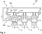
- FIG 3 shows a schematic cross-sectional view of an exemplary embodiment of a connector assembly 100 with a connector strip assembly 1 according to Figure 2 .
- the cross-sectional view corresponds to a cross-section as indicated by the dotted line A-A in Figure 2 , when the connector strip 1 is assembled to the device 80 by screws 81 extending through the oblong holes 13 and the device 80.
- the connector assembly 100 further comprises a housing 90 with a top cover 90a and a connector housing 90b with openings for the terminal connectors 21, 31, 41, 51, 61, 62, 63 (with terminal connectors 21, 31, 41, 51 not shown according to the selected cross-sectional view) to be connected with counter-connectors 71, 72, 73.
- the terminal connector 61 comprises a terminal assembly 61a with electric terminals 61a2 mold in a mold portion 61a1.
- the electric terminals 61a2 extend from a counter-connector terminal portion to a device contact terminal portion 61a3 in a main direction or contact direction, respectively.
- the counter-connector terminal portions of respective electric terminals 61a2 are exposed from the terminal connector 61 in a direction towards a counter connector 71 to be connected thereto.
- the counter-connector terminal end portions are to be received in respective counter-connector sockets 71a, 71b.
- the counter-connector terminal portions may be configured as sockets with the counter-connector 71 providing exposed electric terminals to be received by such sockets.
- the device contact terminal portion 61a3 of each electric terminal 61a2 is exposed from the mold portion 61a1 and extends in an opposite direction from the terminal connector 61 with respect to the counter-connector terminal portion.
- the device contact terminal portions 61a3 provide a meander shape with meanders deflecting partially away and towards the main direction.
- the meanders thereby allow a length compensation in the main direction.
- the device contact terminal portions 61a3 may provide in the main direction equal to an expected maximum distance between the device 80 and the mold portion 61a1, when assembled, due to tolerances. Accordingly, even if the distance is smaller within the applicable range of tolerances, the meanders allow the device contact terminal portion 61a3 to be compressed without applying significant pressure on the device 80 or breakage.
- the ability of the device contact terminal portion 61a3 to be compressed in the main direction also allows to compensate for thermal expansions in the main direction.
- the invention has been described in with respect to exemplary embodiments. However, the invention is not limited to the exemplary embodiments.
- the exemplary embodiments show an assembly of terminal connectors 21, 31, 41, 51, 61, 62, 63 in terminal connector frames 20, 30, 40, 50, 60 at least some of the terminal connectors 21, 31, 41, 51, 61, 62, 63 may be integrally formed with respective terminal connector frames 20, 30, 40, 50, 60, e.g. by injection molding or over molding of a respective assembly, to be directly connected to the connector frame 10 in a respective connector frame opening 11, 12.
- the connector assembly is described with respect to configuration comprising the device 80 and other components. However, the connector assembly may also be represented by the connector strip assembly 1 only as a pre-assembled module.
Landscapes
- Connector Housings Or Holding Contact Members (AREA)
Abstract
at least one connector frame opening (11, 12),
wherein the connector frame opening (11, 12) is configured to receive at least one terminal connector frame (20, 30, 40, 50, 60) and/or at least one terminal connector (21, 31, 41, 51, 61, 62, 63) by a form-fit and/or force-fit connection.
Description
- The present invention relates to a connector frame, a terminal connector frame, and a terminal connector for a connector assembly for an electric connection of a device in a connector-to-counter-connector configuration as well as a respective connector assembly.
- Connector assemblies for an electric connection of a device in a connector-to-counter-connector configuration are, for example, used to provide an electrical connection between contacts of a printed circuit board and HDSCS connectors as counter-connectors. As different types of HDSCS, other counter-connectors or combinations thereof are used in different applications with different printed circuit boards as devices, the efforts to manufacture and handle the individual variations are significant.
- For example, multiple connector strips corresponding to different counter-connectors or variations have to be handled and assembled on a respective device. This leads to more space consumption and increased requirements with respect to an appropriate dimensional alignment with counter assembly parts. Further, the multiple connector strips and dimensional constraints may result in an arrangement, which is not ergonomic for connecting a respective counter-connector.
- In view of the above, it is an object of the present invention to provide a connector frame, a terminal connector frame, and a terminal connector for a connector assembly for an electric connection of a device in a connector-to-counter-connector configuration as well as a respective connector assembly allowing a plurality of counter-connectors to be flexibly electrically connected to the connector assembly.
- The object is solved by a connector frame according to
claim 1, a terminal connector frame according to claim 6, a terminal connector according toclaim 10 and a connector assembly according toclaim 12. Further aspects of the present invention are subject to the dependent claims. - According to the present invention, a connector frame for a connector assembly for an electric connection of a device in a connector-to-counter-connector configuration, comprises at least one connector frame opening, wherein the connector frame opening is configured to receive at least one terminal connector frame and/or at least one terminal connector by a form-fit and/or force-fit connection.
- With the connector frame comprising at least one connector frame opening to receive at least one terminal connector frame and/or at least one terminal connector by a form-fit and/or force-fit connection, the configuration of terminal connectors or at least terminal connector frames may be adapted easily by populating and depopulating the connector frame according to the given application in an easy manner.
- Accordingly, a single adaptable connector strip as a connector assembly or as part of a connector assembly may be provided by at least one connector frame comprising at least one terminal connector frame and/or at least one terminal connector received in the at least one connector frame opening. As will be described later, the at least one terminal connector frame is a frame member to receive a terminal connector to be positioned in the connector frame. Alternatively, the at least one terminal connector may be configured to be directly received in the connector frame.
- To provide a form-fit and/or force fit connection of the at least one terminal connector frame and/or the at least one terminal connector with the connector frame and the at least one connector frame opening, respectively, the at least one terminal connector frame and/or the at least one terminal connector may comprise form-fit and/or force-fit means, such as snap-fit members, snap-fit member receiving portions, through holes for fixing screws or the like. Analogously, the connector frame comprises corresponding form-fit and/or force-fit means at or near the at least connector frame opening. In addition, the at least one terminal connector frame and/or the at least one terminal connector may comprise further form-fit and/or force-fit means to connect terminal connector frames and/or the terminal connectors facing each other in a longitudinal direction when assembled. The longitudinal direction refers to the largest extension of the connector frame opening in the frame plane as a length of the connector frame opening.
- In some embodiments, the connector frame comprises at least two connector frame openings, each of which providing the largest extension of the opening in the frame plane as length. The at least two connector frame openings are arranged in parallel to each other with their respective lengths at least partially facing each other.
- Accordingly, the connector frame comprises at least two rows of connector frame openings with each row extending in the longitudinal direction. Preferably, at least one of the at least two connector frame openings does not extend beyond another one of the at least two connector frame openings in the longitudinal direction. Accordingly, the most compact arrangement in the longitudinal direction may be provided for the given lengths of the at least two connector frame openings. In particular, the at least two connector frame openings are configured to provide similar lengths to distribute the terminal connector frames and/or the terminal connectors in an almost rectangular arrangement. For example, the connector frame may be intended to allow the accommodation of seven partially different terminal connectors to receive corresponding HDSCS counter-connectors, e.g. one 7-pin, one 4-pin, one 3-pin, two inline 4-pin and two 6-pin HDSCS counter-connectors. In such configuration, the connector terminal frame may provide a first connector frame opening to receive the terminal connectors to be connectable to the 7-pin, the two inline 4-pin and the 3-pin HDSCS counter-connectors adjacent to each other in the longitudinal direction of the first connector frame opening as a first terminal connector arrangement. A second connector frame opening may be configured to receive the connector terminals to be connectable to the two 6-pin and the 4-pin HDSCS counter-connectors adjacent to each other in the longitudinal direction of the second connector frame opening as a second terminal connector arrangement.
- The first and second terminal connector arrangement provide a similar space consumption in the longitudinal direction. Accordingly, arranging the first connector frame opening and the second connector frame opening as two rows with the connector frame opening having a length equal or smaller than the other connector frame opening not extending beyond the other connector frame opening in the longitudinal direction supports a compact design in such direction.
- For example, such configuration may allow to provide a connector frame or a connector strip, respectively, for accommodating the seven terminal connectors within an overall dimension of 104 mm in the longitudinal direction and 95.5 mm in a direction perpendicular to the longitudinal direction in the frame plane. The frame plane extends in plane to face the device and the device contact portion when assembled to the device.
- Alternatively or in addition, at least two rows of terminal connector frames and/or terminal connectors may be provided in at least one connector frame opening. In such configuration the terminal connector frames and/or the terminal connectors may also comprise form-fit and/or force-fit means to connect terminal connector frames and/or the terminal connectors facing each other in a direction perpendicular to the longitudinal direction in the frame plane. The same principles as described for at least two connector frame openings as two rows also apply for the at least two rows of terminal connector frames and/or terminal connectors within one connector frame opening.
- With two rows of connector frames and/or two rows of terminal connector frames and/or terminal connectors, each terminal connector frame and/or terminal connector may be accessible from at least one side by requiring less space in the longitudinal direction in comparison to an arrangement in one row only.
- In some embodiments, the connector frame comprises at least one oblong hole configured such that the connector frame is attachable to the device and such that a relative position of the connector frame is adjustable with respect to the device.
- The at least one oblong hole may allow to compensate for tolerances when assembling the connector frame as connector strip to the device directly or to a connector strip as part thereof to be attached to the device indirectly. Alternatively or in addition, the at least one oblong hole may be configured to achieve different relative positions of the connector frame with respect to the device to allow terminal connectors and electric terminals, respectively, to be connectable to different contact portions of the device.
- The at least one oblong hole is preferably arranged at an outer circumference, i.e. in a portion near an outer edge, of the connector frame to support accessibility during assembling or disassembling. For example, the connector frame may be of a rectangular shape in the frame plane and may comprise four oblong holes in each corner. Alternatively or in addition, oblong holes may be provided near the outer edge of the connector frame in an intermediate or central position between two subsequent corners.
- In some embodiments, the connector frame comprises at least one pressure relief member.
- The pressure relief member may be a burst disc, for example a burst disc of 1.5 mm in thickness and 7 mm in diameter. The burst disc may be press fitted inside a hole in the connector frame, for example with a hole diameter of 5.95 mm. The material of the burst disc may be 50 VMQ 570. The relief member may be configured to break open or burst off if the pressure inside the connector exceeds a predetermined pressure increase threshold, e.g. an increase of more than 2.5 bars. The change in pressure inside the connector may be due to temperature changes caused by heat emitted by electronic components on a printed circuit board as device within the connector.
- In some embodiments, the connector frame comprises at least one sealing member enclosing the at least one connector frame opening and/or the at least one pressure relief member.
- The at least one sealing member may be arranged near the outer circumference of the connector frame to be in contact with the device when the connector frame is assembled thereto. Accordingly, components within a space between the device and the connector frame enclosed by the at least one sealing member may be protected from external influences. Alternatively or in addition, the at least one sealing member or a further sealing member, respectively, may be arranged in the frame plane one a side facing away from the device when the connector frame is assembled thereto. The sealing member may thereby provide a sealing with a housing or other components being arranged on the side of the connector frame facing away from the device. Other components within the housing or next to the other components may therefore be protected.
- In a further aspect, the present invention relates to a terminal connector frame for a connector assembly for an electric connection of a device in a connector-to-counter-connector configuration, configured to be received by a connector frame, preferably a connector frame as previously described, wherein the terminal connector frame comprises at least one terminal connector and/or at least one terminal connector frame opening configured to receive at least one terminal connector by a form-fit and/or force-fit connection.
- The at least one terminal connector comprised by the terminal connector frame may be integrally formed with the terminal connector frame, e.g. by being molded as an integral component. Alternatively, the at least one terminal connector may be receivable by the terminal connector frame proving a terminal connector frame opening. The terminal connector frame opening is configured to receive the at least one terminal connector by a form-fit and/or force-fit connection. For the form-fit and/or force-fit connection, the same principle as for the form-fit and/or force-fit connection described with respect to the connector frame opening may apply.
- The terminal connector frame may be configured to close the connector frame opening at least in a direction perpendicular to the longitudinal direction of the connector frame opening. In some configurations, the terminal connector frame may also be configured to close the connector frame opening in the longitudinal direction. In such configuration, the terminal connector frame may comprise more than one terminal connectors and/or more than one terminal connector frame openings. Instead of closing the connector frame opening in the longitudinal direction by one terminal connector frame, the connector frame opening may be closable by a plurality of terminal connector frames received adjacent to each other in the longitudinal direction. Closing the at least one connector frame opening by the at least one terminal connector frame or a plurality of terminal connector frames allows protection of components within the space between the device and the connector frame or connector strip, respectively, when the connector frame is assembled to the device. Instead of closing the at least one connector frame opening by the at least one terminal connector frame or a plurality of terminal connector frames, the at least one connector frame opening or at least a portion thereof not occupied by a respective terminal connector frame may be closed by a filler plate or filler plug. Such filler plate or filler plug may be configured like the terminal connector frame without a terminal connector but with a closed surface. Alternatively, the filler plate or filler plug may be configured to close the at least one terminal connector frame opening. The filler plate or plug is preferably configured to be removable from the connector frame opening or the terminal connector frame opening to allow to be replaced by a terminal connector frame or a terminal connector.
- In some embodiments, the terminal connector frame comprises at least one terminal assembly to provide at least one terminal connector with at least one electric terminal configured to electrically connect at least one counter-connector with a device in a connector-to-counter-connector configuration by a device contact terminal portion of the at least one electric terminal.
- Accordingly, the at least one terminal assembly comprising at least one electric terminal may be assembled to the device by assembling the connector frame to the device with the terminal connector frame comprised thereby. The connector frame, the terminal connector frame and the terminal assembly, respectively, are configured such that the device contact terminal portion contacts a corresponding device contact portion of the device when the connector frame is assembled to the device. Alternatively or in addition, the connector frame, the terminal connector frame and the terminal assembly, respectively, are configured to allow the position of the device contact terminal portion to be adapted. In such configuration, tolerances may compensated and/or different contact positions may be achievable.
- Preferably, the at least one terminal assembly comprises at least one mold portion with the at least one electric terminal mold in the mold portion.
- The mold portion may be attached to the terminal connector frame or integrally formed therewith. Accordingly, the at least one electric contact arranged in a predetermined position within the mold portion may also provide a predetermined position with respect to the terminal connector frame. In some configurations, the terminal assembly may provide a plurality of electric terminals. With the plurality of electric terminals being mold in the mold portion, the electric terminals may be already provided in predetermined relative positions to each other to ease a later assembling.
- In some embodiments, the device contact terminal portion of the at least one electric terminal of the at least one terminal assembly is an exposed end of the at least one terminal assembly configured to be in contact with an electric contact of the device in an electric connection of a device in a connector-to-counter-connector configuration comprising at least two turning points to deflect the extension of the electric terminal at least once from a main direction, in which the electric terminal extends in a contact direction.
- The device contact terminal portion is intended to be positioned in electric contact with a device contact, for example, an electric contact of a printed circuit board as an exemplary device. The counter-connector terminal portion as the other end of the electric terminal is intended to be positioned in electric contact with a counter-connector contact, for example, by being received in a socket of a HDSCS connector as exemplary counter-connector. The main direction, in which the electric terminal extends from the device contact terminal portion to the counter-connector terminal portion, represents a virtual direct connection, i.e. a straight line, between the device contact terminal portion and the counter-connector terminal portion. The electric terminal does not necessarily have to physically extend at least partially along the main direction. In other words, the electric terminal may but not have to extend physically at least partially along the main direction but the extension of the electric terminal is oriented in such main direction.
- The device contact terminal portion of the at least one electric terminal of the at least one terminal assembly being an exposed end of the at least one terminal assembly may allow at least partial compensation of a thermal expansion of the electric terminal and/or at least partial compensation of tolerances in the main direction. Specifically, according to the modular configuration when assembling the terminal assembly to the terminal connector to be connected to the terminal connector frame or the connector frame, the device contact terminal portion allowing compensation of tolerances may provide a significant advantage.
- Due to the at least two turning points the electric terminal at least once extends in a direction different from the main direction. A thermal expansion of the electric terminal may be at least partially compensated, for example, by the at least two turning points being displaced in the event of a thermal expansion. For example, the electric terminal end may be provided in a z-shape with the electric terminal extending in the device contact terminal portion in a first direction with a first turning point deflecting the electric terminal, for example, by 90° in a second direction. At a second turning point of the device contact terminal portion, the electric terminal is again deflected, for example, by 90° to further extend to the counter-connector terminal portion in the first direction. With the first direction being mainly relevant with respect to the electric connection of a device in a connector-to-counter-connector configuration and the device contact terminal portion and the counter-connector terminal portion being clamped between the device and the counter-connector in the main direction when assembled to the device, the first turning point may be displaced towards the counter-connector terminal portion and the second turning point is displaced towards the device contact terminal portion. The electric terminal portion between the first turning point and second turning point is thereby moved to be inclined with respect the former angles of 90°. Tolerances in the main direction may be compensated by the device contact terminal portion being configured to provide an exposed length in the main direction corresponding to a predetermined maximum distance to be bridged by the device contact terminal portion to contact the device when assembled. Even if the distance is shorter due to tolerances or the like, the at least two turning points to deflect the extension of the electric terminal allow a compression of the device contact terminal portion.
- In some embodiments, the device contact terminal portion is at least partially flexible in the main direction. Accordingly, a compensation of a thermal expansion of the electric terminal and/or tolerances may therefore, alternatively or in addition to the displacement of at least one of the at least two turning points, be provided by an elastic deformation of at least a part of the device contact portion. The flexibility to allow a respective elastic deformation may be provided by the elastic properties according to material selection for the electric terminal or at least the respective portion of the device contact terminal portion, the dimensions of the respective portion of the device contact terminal portion and/or the shape of the respective portion of the device contact terminal portion. For example, the respective portion of the device contact terminal portion may be provided as a flexure bearing, flexible in the main direction. The ability for an elastic deformation preferably corresponds at least to the expected thermal expansion and/or expected tolerances according to a given application in terms of expected temperatures and thermal expansion coefficients and/or expected tolerances to be considered.
- Turning back to the previous example of a z-shaped electric terminal, the electric terminal portion between the first turning point and the second turning point may be configured as thin stripe to elastically flex in the main direction with respect to the first turning point and/or the second turning point.
- In some embodiments, the device contact terminal portion is a meander portion comprising at least one meander deflecting the extension of the electric terminal away from and back towards the main direction. Such meander portion in configured to operate like a spring member to be compressed in the main direction due to thermal expansion of the electric terminal and/or tolerances when the device contact terminal portion and the counter-connector terminal portion are clamped between the device and the counter-connector in the main direction. With a plurality of meanders subsequent in the main direction, the ability to compensate for thermal expansions and/or tolerances may be further enhanced. For example, a plurality of subsequent meanders may increase the ability to compensate for thermal expansions and/or tolerances without increasing the required radial space with respect to the main direction in comparison to one meander. Alternatively or in addition, a plurality of subsequent meanders may require less flexibility of each meander in comparison to one single meander, which may allow another material selection and/or other dimensions and/or other shapes.
- In some embodiments, the device contact terminal portion and the counter-connector terminal portion are on the same axis extending in parallel to the main direction, preferably a symmetry axis of the at least one meander. Accordingly, the electric terminal may be compressed by a thermal expansion of the electric terminal and/or by tolerances in the main direction when the device contact terminal portion and the counter-connector terminal portion are clamped between the device and the counter-connector in the main direction. In other words, the electric terminal is less prone to deflect from the main direction when being compressed. Consequently, the electric terminal remains a sufficient stiffness against an excessive compression, which may otherwise result in plastic deformation.
- In a further aspect, the present invention relates to a terminal connector for a connector frame, preferably a connector frame as previously described, and/or a terminal connector frame, preferably for a terminal connector frame as previously described, wherein the terminal connector comprises at least one connection member to connect the terminal connector to the connector frame or the terminal connector frame by a form-fit and/or force-fit connection.
- The terminal connector may be provided as a socket to receive a corresponding counter-connector. The at least one connection member to connect the terminal connector to the connector frame or the terminal connector frame by a form-fit and/or force-fit connection may be a snap-fit member or the like as already addressed with respect to principles of a form-fit and/or force fit connection. Preferably, the at least one connection member is configured to allow the terminal connector to be removable, preferably in a non-destructive manner, to allow replacement of the terminal connector.
- In some embodiments, the terminal connector comprises the at least one terminal assembly as previously described.
- The at least one electric terminal is thereby already provided by the terminal connector. The at least one electric terminal may therefore be attached to the terminal connector via the mold portion of the terminal assembly. The terminal connector may comprise at least one through hole, to let the at least one electric terminal pass there through.
- Alternatively, the mold portion is formed by the terminal connector. The terminal connector comprising the at least one terminal assembly may provide a configuration with the counter-connector terminal portion being exposed from one side of the terminal connector to be connected to a counter-connector and the device contact terminal portion being exposed from the opposed other side of the terminal connector to be connected to the device.
- In a further aspect, the present invention relates to a connector assembly for an electric connection of a device in a connector-to-counter-connector configuration, comprising at least one connector frame, preferably a connector frame as previously described, with at least one terminal connector frame, preferably with at least one terminal connector frame as previously described, and/or at least one terminal connector, preferably at least one terminal connector as previously described, received in a connector frame opening by a form-fit and/or force-fit connection.
- In accordance with the previous description of the connector frame, the terminal connector frame and the terminal connector, the modular configuration of a respective connector assembly allows a flexible assembling of different terminal connector configurations and may provide less space consumption.
- Preferably, the connector assembly comprises the device to be electrically connected to a counter-connector, and wherein the connector frame is attached to the device, preferably by at least one screw passing through the at least one oblong hole of the connector frame and the device, with at least one device contact terminal portion of an electric terminal provided by the at least one terminal connector or the at least one terminal connector frame being in contact with an electric contact of the device by such attachment.
- Accordingly, the connector assembly with the device in electric contact with the at least one device contact terminal portion of the at least one electric terminal may be provided as pre-assembled module for a given application.
- Preferably, the device comprises several electric contact configurations in a device portion assigned to the at least one terminal connector or the at least one terminal connector frame to allow an electrical connection of different terminal assemblies in such device portion.
- As the connector assembly allows a flexible configuration of terminal connectors and electric terminals, respectively, the several electric contact configurations of the device correspond thereto. For example, a device portion of the device allows to be electrically connected to a terminal assembly to be connected to a 6-pin HDSCS counter-connector as well as to a 4-pin HDSCS counter-connector by an electric contact pattern of the device allowing both.
- Further advantages, aspects and details of the invention are subject to the claims, the following description of preferred embodiments applying the principles of the invention, and drawings. In particular:
-
Figure 1 is a schematic front view of a connector frame according to an exemplary embodiment of the present invention; -
Figure 2 is a schematic front view of a connector strip assembly comprising a connector frame according toFigure 1 , exemplary terminal connector frames and terminal connectors according to an exemplary embodiment of the present invention; and -
Figure 3 is a schematic cross-sectional view of an exemplary embodiment of a connector assembly with a connector strip assembly according toFigure 2 . -
Figure 1 shows a schematic front view of aconnector frame 10 according to an exemplary embodiment of the present invention. Theconnector frame 10 comprises a firstconnector frame opening 11 and a secondconnector frame opening 12. Each of the firstconnector frame opening 11 and the secondconnector frame opening 12 provides a substantially rectangular shape with a length l1, l2 as the largest extension in the frame plane. The frame plane is the plane comprising the firstconnector frame opening 11 and the secondconnector frame opening 12 and intended to face a device 80 (Figure 3 ) when assembled to such device. The firstconnector frame opening 11 and the secondconnector frame opening 12 are arranged to form two rows with the lengths l1, l2 facing each other. In the exemplary embodiment, the length l2 of the secondconnector frame opening 12 is slightly smaller than the length l1 of the firstconnector frame opening 11 and arranged to not extend beyond the first connector frame opening 11 in a longitudinal direction L. Accordingly, the secondconnector frame opening 12 does not require further space in the longitudinal direction L in addition to the space in the longitudinal direction L already required for the firstconnector frame opening 11. - Therefore, the
connector frame 10 is provided in a compact configuration with respect to its dimensions in the longitudinal direction L. In alternative embodiments, the first and secondconnector frame openings connector frame 10 according to specific application constraints. The same applies for the shape of theconnector frame 10, which is of a substantially rectangular shape to support a compact configuration in the given exemplary embodiment, but may be of a different shape in alternative embodiments to account for different application requirements. - The
connector frame 10 further comprisesoblong holes 13 disposed at two outer periphery portions of theconnector frame 10 opposed two each other in the longitudinal direction L. Here, each of the outer periphery portions comprises threeoblong holes 13 arranged in a row perpendicular to the longitudinal direction L with the outeroblong holes 13 in such row are disposed in corner portions of theconnector frame 10. In alternative embodiments, the number and arrangement of theoblong holes 13 and/or rows may be different. For example, only oneoblong hole 13 or only oneoblong hole 13 per row or only one row at all may be comprised by theconnector frame 10. As another variant, the connector frame may only provideoblong holes 13 in the corner portions. Further, the rows ofoblong holes 13 may extend alternatively or in addition in the longitudinal direction L. The oblong holes 13 are configured to allow adaption of the relative position of theconnector frame 10 when assembling theconnector frame 10 to a counter-part, here to thedevice 80 as described later. The adaption of the relative position allows to compensate for tolerances and/or to assemble theconnector frame 10 to different devices and/or in different positions. - Additionally, the
connector frame 10 comprises a pressure relief member 14. The pressure relief member 14 is a safety feature configured to break open when high pressure is applied. In the exemplary embodiment, the pressure relief member 14 is a pressure relief burst disc. Here, the pressure relief member 14 is arranged between the firstconnector frame opening 11 and the secondconnector frame opening 12. Here, the pressure relief member 14 is a burst disc with 1.5mm in thickness and 7 mm in diameter. The pressure relief member 14 is press fitted inside a corresponding hole in theconnector frame 10 with a diameter of 5.95 mm. This pressure relief member 14 is of the material 50 VMQ 570. The pressure relief member 14 will break open or burst off if the pressure inside a connector 100 (Figure 3 ) increases more than 2.5 bars. The change in pressure inside theconnector 100 may be due to temperature changes caused by heat emitted by electronic components on the printed circuit board as a device 80 (Figure 3 ). - The
connector frame 10 further comprises a sealingmember 15 enclosing the firstconnector frame opening 11, the secondconnector frame opening 12 and the pressure relief member 14. The sealingmember 15 is configured to be pressed against an abutment portion of a counter-part, e.g. a housing of another component, to seal an area within the enclosure by the sealingmember 15 from an outside thereof and vice versa. In alternative embodiments, a plurality of sealing members may be provided to allow an individual enclosure of the firstconnector frame opening 11, the secondconnector frame opening 12 and/or the pressure relief member 14 or combinations thereof. -
Figure 2 shows a schematic front view of aconnector strip assembly 1 comprising aconnector frame 10 according toFigure 1 , exemplary terminal connector frames 20, 30, 40, 50, 60 andterminal connectors - The terminal connector frames 20, 30, 40, 50 are accommodated in the first connector frame opening 11 in a row in the longitudinal direction L by snap-fits (not shown) to be received by corresponding recesses (not shown) of the
connector frame 10 in the periphery of the first connector frame opening 11 to form a form-fit connection. Similarly, theterminal connector frame 60 is accommodated in the second connector frame opening 12 by a form-fit connection. The form-fit connection members of the terminal connector frames 20, 30, 40, 50, 60 are configured to correspond to each other to allow the terminal connector frames 20, 30, 40, 50, 60 to be arranged in an exchanged order or in another connector frame. Therefore, also the firstconnector frame opening 11 and the second connector frame opening 12 comprise corresponding form-fit members, here recesses, and the same dimension in a direction perpendicular to the longitudinal direction L to allow such different arrangements. Further, the dimensions of the terminal connector frames 20, 30, 40, 50 are the same in the longitudinal direction L. In alternative embodiments, the terminal connector frames 20, 30, 40, 50, 60 and/or the firstconnector frame opening 11 and secondconnector frame opening 12 may provide at least partially different connection members and/or dimensions to prevent at least one of the exemplary terminal connector frames 20, 30, 40, 50, 60 to be arranged in any position. In other embodiments, the connection members may alternatively or in addition form a force-fit connection. The described configuration may achieve better tolerances of connector pins at a printed circuit board side for soldering. - In other embodiments, the terminal connector frames 20, 30, 40, 50, 60 and
terminal connectors connector frame 10 by over molding. Similarly, theterminal connector frame 60 is accommodated in the second connector frame opening 12 by the form-fit connection may be further secured by over molding. - Each of the terminal connector frames 20, 30, 40, 50 accommodated in the first
connector frame opening 11 comprises one terminal connector frame opening (not shown as occupied by the andterminal connectors terminal connectors connector frame openings pin terminal connector 21 is received in the terminal connector frame opening of theterminal connector frame 20, inline 4-pin terminal connectors pin terminal connector 41 is received in the terminal connector frame opening of theterminal connector frame 40. As theterminal connectors terminal connectors connector frame 10 close the firstconnector frame opening 11. In alternative embodiments, when a connector frame opening is not closed by respective terminal connector frames for a given application, respective gaps in such connector frame opening may be closed by filler plates or filler plugs. - The second
connector frame opening 12 accommodates theterminal connector frame 60 with three terminal connector frame openings to receive theterminal connectors terminal connector frame 12 may accommodate theterminal connectors terminal connector frame 60 accommodates two 6-pin terminal connectors pin terminal connector 62. - Each of the
terminal connectors terminal connectors Figure 2 , an exemplary electric terminal 61a2 is indicated. -
Figure 3 shows a schematic cross-sectional view of an exemplary embodiment of aconnector assembly 100 with aconnector strip assembly 1 according toFigure 2 . The cross-sectional view corresponds to a cross-section as indicated by the dotted line A-A inFigure 2 , when theconnector strip 1 is assembled to thedevice 80 byscrews 81 extending through theoblong holes 13 and thedevice 80. Theconnector assembly 100 further comprises ahousing 90 with atop cover 90a and aconnector housing 90b with openings for theterminal connectors terminal connectors - An electric connection of the
terminal connectors terminal connector 61. The description is also applicable for the otherterminal connectors terminal connector 61 comprises aterminal assembly 61a with electric terminals 61a2 mold in a mold portion 61a1. The electric terminals 61a2 extend from a counter-connector terminal portion to a device contact terminal portion 61a3 in a main direction or contact direction, respectively. The counter-connector terminal portions of respective electric terminals 61a2 are exposed from theterminal connector 61 in a direction towards acounter connector 71 to be connected thereto. The counter-connector terminal end portions are to be received in respectivecounter-connector sockets terminal connector 61 with respect to the counter-connector terminal portion. When the connector strip assembly is assembled to thedevice 80 by attaching theconnector frame 10 to thedevice 80 via thescrews 81, the device contact terminal portions are in contact with respective device contact portions of thedevice 80 for electrical contact. To allow a compensation of tolerances and thermal expansions, the device contact terminal portions 61a3 provide a meander shape with meanders deflecting partially away and towards the main direction. The meanders thereby allow a length compensation in the main direction. For example, with the device contact terminal portions configured to compensate for tolerances, the device contact terminal portions 61a3 may provide in the main direction equal to an expected maximum distance between thedevice 80 and the mold portion 61a1, when assembled, due to tolerances. Accordingly, even if the distance is smaller within the applicable range of tolerances, the meanders allow the device contact terminal portion 61a3 to be compressed without applying significant pressure on thedevice 80 or breakage. The ability of the device contact terminal portion 61a3 to be compressed in the main direction also allows to compensate for thermal expansions in the main direction. - The invention has been described in with respect to exemplary embodiments. However, the invention is not limited to the exemplary embodiments. In particular, even though the exemplary embodiments show an assembly of
terminal connectors terminal connectors connector frame 10 in a respectiveconnector frame opening device 80 and other components. However, the connector assembly may also be represented by theconnector strip assembly 1 only as a pre-assembled module. -
- 1
- connector strip assembly
- 10
- connector frame
- 11
- first connector frame opening
- 12
- second connector frame opening
- 13
- oblong hole
- 14
- pressure relief member
- 15
- sealing member
- 20
- terminal connector frame
- 21
- terminal connector
- 30
- terminal connector frame
- 31
- terminal connector
- 40
- terminal connector frame
- 41
- terminal connector
- 50
- terminal connector frame
- 51
- terminal connector
- 60
- terminal connector frame
- 61
- terminal connector
- 61a
- terminal assembly
- 61a1
- mold portion
- 61a2
- electric terminal
- 61a3
- device contact terminal portion
- 62
- terminal connector
- 63
- terminal connector
- 71
- counter-connector
- 71a, 71b
- counter-connector socket
- 72
- counter-connector
- 73
- counter-connector
- 80
- printed circuit board (device)
- 81
- screw
- 90
- housing
- 90a
- top cover
- 90b
- connector housing
- 100
- connector assembly
- l1
- length (connector frame opening 11)
- l2
- length (connector frame opening 12)
- L
- longitudinal direction
Claims (14)
- Connector frame (10) for a connector assembly (100) for an electric connection of a device (80) in a connector-to-counter-connector configuration, comprisingat least one connector frame opening (11, 12),wherein the connector frame opening (11, 12) is configured to receive at least one terminal connector frame (20, 30, 40, 50, 60) and/or at least one terminal connector (21, 31, 41, 51, 61, 62, 63) by a form-fit and/or force-fit connection.
- The connector frame (10) according to claim 1, wherein the connector frame (10) comprises at least two connector frame openings (11, 12), each of which providing the largest extension of the opening in the frame plane as length (11, 12), and wherein the at least two connector frame openings (11, 12) are arranged in parallel to each other with their respective lengths (11, 12) at least partially facing each other.
- The connector frame (10) according to claim 1 or 2, wherein the connector frame (10) comprises at least one oblong hole (13) configured such that the connector frame (10) is attachable to the device (80) and such that a relative position of the connector frame (10) is adjustable with respect to the device (80).
- The connector frame (10) according to any one of the claims 1 to 3, wherein the connector frame (10) comprises at least one pressure relief member (14).
- The connector frame (10) according to any one of the claims 1 to 4, wherein the connector frame (10) comprises at least one sealing member enclosing the at least one connector frame opening (11, 12) and/or the at least one pressure relief member (14).
- Terminal connector frame (20, 30, 40, 50, 60) for a connector assembly (100) for an electric connection of a device (80) in a connector-to-counter-connector configuration, configured to be received by a connector frame (10), preferably a connector frame (10) according to one of the claims 1 to 5, wherein the terminal connector frame (20, 30, 40, 50, 60) comprises at least one terminal connector (21, 31, 41, 51, 61, 62, 63) and/or at least one terminal connector frame opening configured to receive at least one terminal connector (21, 31, 41, 51, 61, 62, 63) by a form-fit and/or force-fit connection.
- The terminal connector frame (20, 30, 40, 50, 60) according to claim 6, wherein the terminal connector frame (20, 30, 40, 50, 60) comprises at least one terminal assembly (61a) to provide at least one terminal connector (21, 31, 41, 51, 61, 62, 63) with at least one electric terminal (61a2) configured to electrically connect at least one counter-connector (71, 72, 73) with a device (80) in a connector-to-counter-connector configuration by a device contact terminal portion (61a3) of the at least one electric terminal (61a2).
- The terminal connector frame (20, 30, 40, 50, 60) according to claim 7, wherein the at least one terminal assembly (61a) comprises at least one mold portion (61a1) with the at least one electric terminal (61a2) mold in the mold portion (61a1).
- The terminal connector frame (20, 30, 40, 50, 60) according to claim 7 or 8, wherein the device contact terminal portion (61a3) of the at least one electric terminal (61a2) of the at least one terminal assembly (61a) is an exposed end of the at least one terminal assembly (61a) configured to be in contact with an electric contact of the device (80) in an electric connection of a device (80) in a connector-to-counter-connector configuration comprising at least two turning points to deflect the extension of the electric terminal (61a2) at least once from a main direction, in which the electric terminal (61a2) extends in a contact direction.
- Terminal connector (21, 31, 41, 51, 61, 62, 63) for a connector frame (10), preferably a connector frame (10) according to one of the claims 1 to 5, and/or a terminal connector frame (20, 30, 40, 50, 60), preferably for a terminal connector frame (20, 30, 40, 50, 60) according to one of the claims 6 to 9, wherein the terminal connector (21, 31, 41, 51, 61, 62, 63) comprises at least one connection member to connect the terminal connector (21, 31, 41, 51, 61, 62, 63) to the connector frame (10) or the terminal connector frame (20, 30, 40, 50, 60) by a form-fit and/or force-fit connection.
- The terminal connector (21, 31, 41, 51, 61, 62, 63) according to claim 10, wherein the terminal connector (21, 31, 41, 51, 61, 62, 63) comprises the at least one terminal assembly (61a) according to one of the claims 7 to 9.
- Connector assembly (100) for an electric connection of a device (80) in a connector-to-counter-connector configuration, comprising at least one connector frame (10), preferably a connector frame according to one of the claims 1 to 5, with at least one terminal connector frame (20, 30, 40, 50, 60), preferably with at least one terminal connector frame (20, 30, 40, 50, 60) according to one of the claims 6 to 9, and/or at least one terminal connector (21, 31, 41, 51, 61, 62, 63), preferably at least one terminal connector (21, 31, 41, 51, 61, 62, 63) according to claim 10 or 11, received in a connector frame opening (11, 12) by a form-fit and/or force-fit connection.
- The connector assembly (100) according to claim 12, wherein the connector assembly (100) comprises the device (80) to be electrically connected to a counter-connector (71, 72, 73), and wherein the connector frame (10) is attached to the device (80), preferably by at least one screw (81) passing through the at least one oblong hole (13) of the connector frame (10) and the device (80), with at least one device contact terminal portion (61a3) of an electric terminal (61a2) provided by the at least one terminal connector (21, 31, 41, 51, 61, 62, 63) or the at least one terminal connector frame (20, 30, 40, 50, 60) being in contact with an electric contact of the device (80) by such attachment.
- The connector assembly (100) according to claim 13, wherein the device (80) comprises several electric contact configurations in a device portion assigned to the at least one terminal connector (21, 31, 41, 51, 61, 62, 63) or the at least one terminal connector frame (20, 30, 40, 50, 60) to allow an electrical connection of different terminal assemblies (61a) in such device portion.
Priority Applications (3)
| Application Number | Priority Date | Filing Date | Title |
|---|---|---|---|
| EP21208779.5A EP4184724A1 (en) | 2021-11-17 | 2021-11-17 | Connector frame, terminal connector frame, terminal connector and connector assembly |
| US18/048,544 US12424804B2 (en) | 2021-11-17 | 2022-10-21 | Connector frame, terminal connector frame, terminal connector and connector assembly |
| CN202211439755.2A CN116137401A (en) | 2021-11-17 | 2022-11-17 | Connector frames, terminal connector frames, terminal connectors and connector assemblies |
Applications Claiming Priority (1)
| Application Number | Priority Date | Filing Date | Title |
|---|---|---|---|
| EP21208779.5A EP4184724A1 (en) | 2021-11-17 | 2021-11-17 | Connector frame, terminal connector frame, terminal connector and connector assembly |
Publications (1)
| Publication Number | Publication Date |
|---|---|
| EP4184724A1 true EP4184724A1 (en) | 2023-05-24 |
Family
ID=78676489
Family Applications (1)
| Application Number | Title | Priority Date | Filing Date |
|---|---|---|---|
| EP21208779.5A Pending EP4184724A1 (en) | 2021-11-17 | 2021-11-17 | Connector frame, terminal connector frame, terminal connector and connector assembly |
Country Status (3)
| Country | Link |
|---|---|
| US (1) | US12424804B2 (en) |
| EP (1) | EP4184724A1 (en) |
| CN (1) | CN116137401A (en) |
Citations (5)
| Publication number | Priority date | Publication date | Assignee | Title |
|---|---|---|---|---|
| EP1193808A2 (en) * | 2000-09-29 | 2002-04-03 | Sumitomo Wiring Systems, Ltd. | Electrical connector |
| WO2008005945A2 (en) * | 2006-06-30 | 2008-01-10 | Molex Incorporated | Compliant pin control module and method for making the same |
| JP2014067550A (en) * | 2012-09-25 | 2014-04-17 | Daiichi Seiko Co Ltd | Electric connector |
| CN104472027A (en) * | 2012-03-16 | 2015-03-25 | 大陆汽车有限公司 | Housing cover panel for accommodating plug-in modules |
| CN108075297A (en) * | 2016-11-15 | 2018-05-25 | 德尔福国际业务卢森堡公司 | Include the pin connector in internal undercut space |
Family Cites Families (4)
| Publication number | Priority date | Publication date | Assignee | Title |
|---|---|---|---|---|
| JP2001085101A (en) * | 1999-09-17 | 2001-03-30 | Yazaki Corp | Connector waterproof structure |
| US6652292B2 (en) * | 2002-02-22 | 2003-11-25 | Molex Incorporated | Electrical connector assembly incorporating printed circuit board |
| US7481676B2 (en) * | 2006-08-30 | 2009-01-27 | Tyco Electronics Corporation | Electrical connector with ESD protection |
| DE102010002765A1 (en) * | 2010-03-11 | 2011-09-15 | Robert Bosch Gmbh | Housing base of a multi-part housing and method for mounting a housing |
-
2021
- 2021-11-17 EP EP21208779.5A patent/EP4184724A1/en active Pending
-
2022
- 2022-10-21 US US18/048,544 patent/US12424804B2/en active Active
- 2022-11-17 CN CN202211439755.2A patent/CN116137401A/en active Pending
Patent Citations (5)
| Publication number | Priority date | Publication date | Assignee | Title |
|---|---|---|---|---|
| EP1193808A2 (en) * | 2000-09-29 | 2002-04-03 | Sumitomo Wiring Systems, Ltd. | Electrical connector |
| WO2008005945A2 (en) * | 2006-06-30 | 2008-01-10 | Molex Incorporated | Compliant pin control module and method for making the same |
| CN104472027A (en) * | 2012-03-16 | 2015-03-25 | 大陆汽车有限公司 | Housing cover panel for accommodating plug-in modules |
| JP2014067550A (en) * | 2012-09-25 | 2014-04-17 | Daiichi Seiko Co Ltd | Electric connector |
| CN108075297A (en) * | 2016-11-15 | 2018-05-25 | 德尔福国际业务卢森堡公司 | Include the pin connector in internal undercut space |
Also Published As
| Publication number | Publication date |
|---|---|
| CN116137401A (en) | 2023-05-19 |
| US12424804B2 (en) | 2025-09-23 |
| US20230155331A1 (en) | 2023-05-18 |
Similar Documents
| Publication | Publication Date | Title |
|---|---|---|
| EP3314677B1 (en) | Battery module with a temperature monitoring assembly | |
| TWI392166B (en) | Electrical connector | |
| CN101499575B (en) | Electrical connector | |
| EP2768083A1 (en) | Connector | |
| US6755683B2 (en) | Printed circuit connector | |
| CN104472027A (en) | Housing cover panel for accommodating plug-in modules | |
| WO2008050666A1 (en) | Connector | |
| KR100731443B1 (en) | Electrical connector | |
| US12424804B2 (en) | Connector frame, terminal connector frame, terminal connector and connector assembly | |
| KR100567587B1 (en) | Electrical connector having a holddown for ground connection | |
| US9472358B2 (en) | Assembling structure of electronic component and electrical junction box | |
| EP1947921B1 (en) | Electronic module | |
| US9391395B2 (en) | Connector assembly | |
| US20090170351A1 (en) | Electrical Connector Adapted To Isolate Mating Forces | |
| BR102022021662A2 (en) | CONNECTOR STRUCTURE, TERMINAL CONNECTOR STRUCTURE, TERMINAL CONNECTOR AND CONNECTOR ASSEMBLY | |
| KR20220155343A (en) | shielded plug connector module | |
| JP7339639B2 (en) | electrical equipment | |
| US7258577B2 (en) | Memory pack | |
| EP4637289A1 (en) | Emc assembly | |
| CN221353219U (en) | Terminal seat, terminal module, connector and electronic equipment assembly | |
| CN218586391U (en) | Electrical connector | |
| CN218300277U (en) | Display screen module | |
| JP7498065B2 (en) | Circuit board housing structure | |
| CN222300895U (en) | Connection device with compensation element and kit for producing such a connection device | |
| JP4333962B2 (en) | connector |
Legal Events
| Date | Code | Title | Description |
|---|---|---|---|
| PUAI | Public reference made under article 153(3) epc to a published international application that has entered the european phase |
Free format text: ORIGINAL CODE: 0009012 |
|
| STAA | Information on the status of an ep patent application or granted ep patent |
Free format text: STATUS: THE APPLICATION HAS BEEN PUBLISHED |
|
| AK | Designated contracting states |
Kind code of ref document: A1 Designated state(s): AL AT BE BG CH CY CZ DE DK EE ES FI FR GB GR HR HU IE IS IT LI LT LU LV MC MK MT NL NO PL PT RO RS SE SI SK SM TR |
|
| STAA | Information on the status of an ep patent application or granted ep patent |
Free format text: STATUS: REQUEST FOR EXAMINATION WAS MADE |
|
| 17P | Request for examination filed |
Effective date: 20231124 |
|
| RAP3 | Party data changed (applicant data changed or rights of an application transferred) |
Owner name: KNORR-BREMSE SYSTEME FUER NUTZFAHRZEUGE GMBH |
|
| RBV | Designated contracting states (corrected) |
Designated state(s): AL AT BE BG CH CY CZ DE DK EE ES FI FR GB GR HR HU IE IS IT LI LT LU LV MC MK MT NL NO PL PT RO RS SE SI SK SM TR |
|
| STAA | Information on the status of an ep patent application or granted ep patent |
Free format text: STATUS: EXAMINATION IS IN PROGRESS |
|
| 17Q | First examination report despatched |
Effective date: 20250422 |