EP4184711A1 - Electronic device - Google Patents
Electronic device Download PDFInfo
- Publication number
- EP4184711A1 EP4184711A1 EP22856860.6A EP22856860A EP4184711A1 EP 4184711 A1 EP4184711 A1 EP 4184711A1 EP 22856860 A EP22856860 A EP 22856860A EP 4184711 A1 EP4184711 A1 EP 4184711A1
- Authority
- EP
- European Patent Office
- Prior art keywords
- antenna board
- fastener
- limiting
- electronic device
- mounting cavity
- Prior art date
- Legal status (The legal status is an assumption and is not a legal conclusion. Google has not performed a legal analysis and makes no representation as to the accuracy of the status listed.)
- Granted
Links
Images




Classifications
-
- H—ELECTRICITY
- H01—ELECTRIC ELEMENTS
- H01Q—ANTENNAS, i.e. RADIO AERIALS
- H01Q1/00—Details of, or arrangements associated with, antennas
- H01Q1/12—Supports; Mounting means
- H01Q1/1207—Supports; Mounting means for fastening a rigid aerial element
-
- H—ELECTRICITY
- H01—ELECTRIC ELEMENTS
- H01Q—ANTENNAS, i.e. RADIO AERIALS
- H01Q1/00—Details of, or arrangements associated with, antennas
- H01Q1/12—Supports; Mounting means
- H01Q1/22—Supports; Mounting means by structural association with other equipment or articles
-
- H—ELECTRICITY
- H01—ELECTRIC ELEMENTS
- H01Q—ANTENNAS, i.e. RADIO AERIALS
- H01Q1/00—Details of, or arrangements associated with, antennas
- H01Q1/12—Supports; Mounting means
- H01Q1/22—Supports; Mounting means by structural association with other equipment or articles
- H01Q1/2258—Supports; Mounting means by structural association with other equipment or articles used with computer equipment
-
- H—ELECTRICITY
- H01—ELECTRIC ELEMENTS
- H01Q—ANTENNAS, i.e. RADIO AERIALS
- H01Q1/00—Details of, or arrangements associated with, antennas
- H01Q1/12—Supports; Mounting means
- H01Q1/22—Supports; Mounting means by structural association with other equipment or articles
- H01Q1/24—Supports; Mounting means by structural association with other equipment or articles with receiving set
- H01Q1/241—Supports; Mounting means by structural association with other equipment or articles with receiving set used in mobile communications, e.g. GSM
- H01Q1/242—Supports; Mounting means by structural association with other equipment or articles with receiving set used in mobile communications, e.g. GSM specially adapted for hand-held use
-
- H—ELECTRICITY
- H01—ELECTRIC ELEMENTS
- H01Q—ANTENNAS, i.e. RADIO AERIALS
- H01Q1/00—Details of, or arrangements associated with, antennas
- H01Q1/12—Supports; Mounting means
- H01Q1/22—Supports; Mounting means by structural association with other equipment or articles
- H01Q1/24—Supports; Mounting means by structural association with other equipment or articles with receiving set
- H01Q1/241—Supports; Mounting means by structural association with other equipment or articles with receiving set used in mobile communications, e.g. GSM
- H01Q1/242—Supports; Mounting means by structural association with other equipment or articles with receiving set used in mobile communications, e.g. GSM specially adapted for hand-held use
- H01Q1/243—Supports; Mounting means by structural association with other equipment or articles with receiving set used in mobile communications, e.g. GSM specially adapted for hand-held use with built-in antennas
-
- H—ELECTRICITY
- H01—ELECTRIC ELEMENTS
- H01Q—ANTENNAS, i.e. RADIO AERIALS
- H01Q1/00—Details of, or arrangements associated with, antennas
- H01Q1/36—Structural form of radiating elements, e.g. cone, spiral, umbrella; Particular materials used therewith
- H01Q1/38—Structural form of radiating elements, e.g. cone, spiral, umbrella; Particular materials used therewith formed by a conductive layer on an insulating support
-
- Y—GENERAL TAGGING OF NEW TECHNOLOGICAL DEVELOPMENTS; GENERAL TAGGING OF CROSS-SECTIONAL TECHNOLOGIES SPANNING OVER SEVERAL SECTIONS OF THE IPC; TECHNICAL SUBJECTS COVERED BY FORMER USPC CROSS-REFERENCE ART COLLECTIONS [XRACs] AND DIGESTS
- Y02—TECHNOLOGIES OR APPLICATIONS FOR MITIGATION OR ADAPTATION AGAINST CLIMATE CHANGE
- Y02E—REDUCTION OF GREENHOUSE GAS [GHG] EMISSIONS, RELATED TO ENERGY GENERATION, TRANSMISSION OR DISTRIBUTION
- Y02E60/00—Enabling technologies; Technologies with a potential or indirect contribution to GHG emissions mitigation
- Y02E60/10—Energy storage using batteries
Definitions
- Embodiments of this application relate to the field of electronic product technologies, and in particular, to an electronic device.
- a sidewall of a middle frame is provided with a mounting cavity for mounting an antenna board.
- the mounting cavity is located outside a battery compartment.
- the electronic devices are provided with increasing functions and larger screens, the electronic devices consume power faster.
- a larger battery is preferred.
- a larger space is also preferred for the battery compartment. Therefore, when the electronic devices have a same volume, the middle frame is located in a limited space outside the battery compartment, and a space of the mounting cavity is limited. As a result, when the antenna board is mounted in the mounting cavity, an operation space is limited.
- the antenna board is fastened in the mounting cavity by using screws, the space of the mounting cavity is small, fastening by screws is inconvenient, and the middle frame and even the battery compartment are easily damaged during a mounting process.
- Embodiments of this application provide an electronic device, to resolve a problem of operation inconvenience in antenna board mounting when a mounting space for mounting an antenna board is small, and a problem that a peripheral component is easily damaged in a mounting process.
- an embodiment of this application provides an electronic device, including a middle frame, an antenna board, and a fastener.
- the middle frame is provided with a mounting cavity, and an inner wall of the mounting cavity is provided with a limiting portion.
- the antenna board is placed in the mounting cavity, and the fastener is capable of being clamped between the limiting portion and an upper end face of the antenna board, to restrict the antenna board from moving upward along a depth direction of the mounting cavity.
- the antenna board mounted in the mounting cavity can be fastened by using the fastener and the limiting portion.
- the limiting portion is integrally formed on the inner wall of the mounting cavity.
- this embodiment of this application further provides a first implementation of the aspect: the mounting cavity is inwardly provided with a limiting protrusion on each of two sidewalls along a width direction, a spacing between the limiting protrusions disposed on the two sidewalls is less than a width of the fastener, and the limiting protrusions form the limiting portion.
- the two limiting protrusions are used to limit the antenna board from two sides along the width direction. This can ensure stability, so that a more balanced acting force is applied to the fastener and the limiting is more stable.
- this embodiment of this application further provides a second implementation of the aspect: the limiting portion is a limiting groove disposed on the inner wall of the mounting cavity, and the fastener is capable of being inserted into the limiting groove and abutting against the upper end face of the antenna board.
- the limiting groove is used to limit the fastener, and the limiting groove does not occupy a space in the mounting cavity, to facilitate the mounting operation of the antenna board.
- this embodiment of this application further provides a third implementation of the aspect: a slot is further disposed on an inner wall at one end of the mounting cavity along a length direction of the mounting cavity, a first end of the antenna board along a length direction of the antenna board is capable of being inserted into the slot, and an upper sidewall of the slot is capable of restricting the antenna board from moving upward.
- a slot is further disposed on an inner wall at one end of the mounting cavity along a length direction of the mounting cavity, a first end of the antenna board along a length direction of the antenna board is capable of being inserted into the slot, and an upper sidewall of the slot is capable of restricting the antenna board from moving upward.
- this embodiment of this application further provides a fourth implementation of the aspect: the mounting cavity includes an upper cavity body and a middle cavity body from top to bottom; and the middle cavity body is provided with the slot, and the upper cavity body outwardly extends away from one end of the slot and forms an avoidance space. Disposing the avoidance space facilitates the mounting operation of the antenna board.
- this embodiment of this application further provides a fifth implementation of the aspect: a bottom of the middle cavity body is further provided with an accommodating groove, a lower end face of the antenna board is further provided with a metal elastomer for connecting to the middle frame, and when the antenna board is mounted in the middle cavity body, the metal elastomer is located in the accommodating groove.
- the fastener and the metal elastomer can respectively act on the antenna board from the end faces on upper and lower sides, so that a location of the antenna board is stable.
- the metal elastomer can provide an elastic acting force to the antenna board, a case of crushing the antenna board is avoided while stability is ensured, and further precision requirements on the limiting portion and the fastener can be reduced.
- this embodiment of this application further provides a sixth implementation of the aspect: the fastener is provided with a first limiting structure, the antenna board is provided with a second limiting structure, and when the fastener abuts against the upper end face of the antenna board, the first limiting structure and the second limiting structure are capable of cooperating with each other to restrict the fastener from moving and being detached from the limiting portion.
- this embodiment of this application further provides a seventh implementation of the aspect: the first limiting structure is a first convex portion upwardly protruding from the fastener, the second limiting structure is a second convex portion upwardly protruding from the upper end face of the antenna board, and the first convex portion is located between the second convex portion and the limiting portion.
- the first convex portion can be restricted from moving to both sides along the length direction, thereby ensuring limiting stability.
- this embodiment of this application further provides an eighth implementation of the aspect: the fastener includes a fastening plate, and the fastening plate partially arches upward and forms the first convex portion.
- the fastener includes a fastening plate, and the fastening plate partially arches upward and forms the first convex portion.
- this embodiment of this application further provides a ninth implementation of the aspect: an end of the first convex portion is further provided with a stopper for abutting against the second convex portion, a bottom of the stopper is capable of abutting against the upper end face of the antenna board, and a limiting block is further disposed on a side that is of an upper portion of the stopper and that faces the second convex portion. This avoids a limiting failure caused by entry of the second convex portion into a gap in a case that the second convex portion abuts against the stopper.
- the limiting block can limit an abutment location of the second convex portion from above, so as to limit the second convex portion to between the upper end face of the antenna board and the limiting block, thereby ensuring a stable limiting effect.
- this embodiment of this application further provides a tenth implementation of the aspect: the upper end face of the antenna board is fixedly provided with a baffle plate, and the baffle plate is upwardly bent towards one end of the first convex portion and forms the second convex portion.
- the baffle plate is upwardly bent towards one end of the first convex portion and forms the second convex portion.
- this embodiment of this application further provides an eleventh implementation of the aspect: one of the first limiting structure and the second limiting structure is a positioning hole and the other is a positioning protrusion, and when the fastener is clamped between the limiting portion and the upper end face of the antenna board, the positioning protrusion is capable of being inserted into the positioning hole.
- the positioning hole cooperates with the positioning protrusion to implement positioning, the overall structure can be simplified while a stable limiting effect can be ensured.
- this embodiment of this application further provides a twelfth implementation of the aspect: the fastener is further provided with an operation portion to facilitate the mounting operation.
- this embodiment of this application further provides a thirteenth implementation of the aspect: the operation portion is capable of being detached from the fastener. No external auxiliary tool is required during mounting, the mounting is convenient, and impact of the operation portion on subsequent mounting or a peripheral structure can be avoided.
- this embodiment of this application further provides a fourteenth implementation of the aspect: the operation portion is formed by bending an end of the fastener, and the operation portion is located in the mounting cavity. This can facilitate the mounting operation, and can avoid impact of the operation portion on subsequent mounting or a peripheral structure.
- Embodiments of the present invention provide an electronic device.
- the electronic device may be a terminal product, such as a mobile phone, a tablet computer, a wearable device, an in-vehicle device, an augmented reality (augmented reality, AR)/virtual reality (virtual reality, VR) device, a notebook computer, an ultra-mobile personal computer (ultra-mobile personal computer, UMPC), a netbook, or a personal digital assistant (personal digital assistant, PDA).
- a specific type of the electronic device is not limited in the embodiments of this application.
- the electronic device includes a screen, a rear cover, and a middle frame.
- the middle frame is located between the screen and the rear cover.
- a middle frame 1 of the electronic device includes a middle plate 12 and a bezel 13.
- the bezel 13 circumferentially surrounds an outer edge of the middle plate 12.
- a battery compartment 7 is provided between the middle plate 12 and the rear cover.
- the battery compartment 7 is configured to house a battery for supplying power to the electronic device.
- the bezel 13 is provided with a mounting cavity 11.
- a depth direction of the mounting cavity 11 is arranged along a thickness direction of the electronic device.
- the mounting cavity 11 is provided on an end face on a rear side of the middle frame 1 ("rear side” specifically refers to a side facing the rear cover).
- the mounting cavity 11 is located outside the battery compartment 7 and is configured to mount an antenna board 2 of the electronic device.
- the electronic devices consume power faster.
- a larger battery is preferred.
- a larger space is also preferred for the battery compartment 7. Therefore, when the electronic devices have a same volume, the middle frame 1 is located in a limited space outside the battery compartment 7, that is, the bezel 13 has a limited width, and an arrangement space of the mounting cavity 11 is limited.
- the antenna board 2 is mounted in the mounting cavity 11, an operation space is limited, and a mounting operation is inconvenient. Therefore, in the embodiments of this application, the antenna board 2 is fastened in the mounting cavity 11 by using a fastener 3. This can ensure mounting stability of the antenna board 2 while simplifying the mounting operation, and can further avoid damage to the middle frame 1 and the battery compartment 7 in a mounting process.
- upper refers to a side facing an opening along the depth direction of the mounting cavity 11
- lower refers to a side facing the inside of the mounting cavity 11 along the depth direction of the mounting cavity 11.
- inner walls of the mounting cavity 11 each are provided with a limiting protrusion 115.
- a spacing between the limiting protrusions 115 provided on the two sidewalls is less than a width of the fastener 3 and greater than a width of the antenna board 2 that corresponds to a location here.
- the fastener 3 can be clamped between an upper end face of the antenna board 2 and the limiting protrusions 115.
- the limiting protrusions 115 are located above the fastener 3 and restrict the fastener 3 from moving upward, and the limiting protrusions 115 form a limiting portion for restricting the fastener 3 from moving upward.
- the antenna board 2 can directly pass through a gap between the two limiting protrusions 115 and enter a mounting groove. Then, the fastener 3 is inserted against the upper end face of the antenna board 2 between the upper end face of the antenna board 2 and the limiting protrusions 115.
- the operations are convenient.
- the limiting protrusions 115 are used to limit the antenna board 2 from two sides along the width direction. This can ensure stability, so that a more balanced acting force is applied to the fastener 3 and the limiting is more stable.
- limiting protrusions 115 are not limited. As shown in FIG. 2 , the limiting protrusions 115 are located at one end of the mounting cavity 11, or the limiting protrusions 115 may be disposed at middle locations in a length direction of the mounting cavity 11. This is not specifically limited.
- an end of the fastener 3 is further provided with a guiding surface 311.
- the guiding surface 311 can avoid abrasion during insertion.
- the guiding surface 311 may be either an arc surface or an inclined surface.
- a limiting groove may be further provided on an inner wall of the mounting cavity, to form the limiting portion for restricting the fastener 3 from moving upward.
- the fastener 3 is inserted into the limiting groove.
- the fastener 3 can abut against the upper end face of the antenna board 2, and an upper groove wall of the limiting groove can restrict the fastener 3 from moving upward, thereby ensuring location stability of the antenna board 2.
- the limiting groove may be disposed on each of the two sidewalls of the mounting cavity 11 along the width direction, or may be disposed on an inner wall at one end of the mounting cavity 11. The limiting groove is used to limit the fastener 3, and the limiting groove does not occupy a space in the mounting cavity 11, to facilitate the mounting operation of the antenna board 2.
- a slot 114 is further disposed on an inner wall of the mounting cavity 11.
- the slot 114 is disposed at one end of the mounting cavity 11.
- the antenna board 2 is a strip-shaped structure. Two ends of the antenna board 2 along its length direction are respectively a first end 21 and a second end 22. During mounting, the first end 21 can be inserted into the slot 114, and an upper sidewall of the slot 114 can limit the first end 21, to prevent the first end 21 from moving upward along the depth direction of the mounting cavity 11.
- the fastener 3 can be clamped between the upper end face of the antenna board 2 and the limiting protrusions 115.
- the limiting protrusions 115 are located above the fastener 3 and restrict the fastener 3 from moving upward, and the fastener 3 restricts the antenna board 2 from moving upward.
- the antenna board 2 is limited by using both the slot 114 and the fastener 3, to prevent the antenna board 2 from moving upward, and further ensure that the antenna board 2 is stably located in the mounting cavity 11.
- a lower end face of the antenna board 2 is further provided with a metal elastomer 4.
- the metal elastomer 4 can be clamped between the antenna board 2 and the middle frame 1 and is configured to implement electrical connection.
- a bottom of the mounting cavity 11 is further provided with an accommodating groove 113. After the antenna board 2 is mounted in the mounting cavity 11, the metal elastomer 4 can be located in the accommodating groove 113, the limiting protrusions 115 can be pressed against the antenna board 2 from above, the antenna board 2 downwardly compresses the metal elastomer 4, and the metal elastomer 4 in a compressed state can provide the antenna board 2 with an upward elastic support force.
- the fastener 3 and the metal elastomer 4 can respectively act on the antenna board 2 from the end faces on upper and lower sides, so that a location of the antenna board 2 is stable.
- the metal elastomer 4 can provide an elastic acting force to the antenna board 2, a case of crushing the antenna board 2 is avoided while stability is ensured, and further precision requirements on the limiting protrusions 115 and the fastener 3 can be reduced.
- the antenna board 2 mounted in the mounting cavity 11 can be fastened by using the fastener 3 and the limiting protrusions 115.
- the limiting protrusions 115 are fixedly provided on the inner walls of the mounting cavity 11.
- the limiting protrusions 115 and the mounting cavity 11 are integrally formed, or may be fastened by soldering or in another manner before factory delivery.
- a large complex operation tool such as a screwdriver.
- the mounting operation can be simplified, and no damage is caused to the inner walls of the mounting cavity 11 and even the adjacent battery compartment 7.
- a quantity of the fasteners 3 is not limited.
- the antenna board 2 may be limited by using two fasteners 3, or the antenna board 2 may be limited by using one fastener 3.
- the quantity of the fasteners 3 may be set based on a length of the antenna board, a length of each fastener, and the like.
- no slot 114 may be disposed in the mounting cavity 11, and the antenna board 2 may be fastened only by using the fastener 3 and the limiting portion (the limiting protrusions 115 or the limiting groove).
- the fastener 3 and the slot 114 are used to limit the antenna board 2, only one fastener 3 needs to be disposed to ensure mounting stability of the antenna board 2 and to further simplify an overall structure while simplifying the mounting operation.
- the mounting cavity 11 is inwardly provided with the limiting protrusions 115 respectively on the two opposite sidewalls along the width direction, the spacing between the two limiting protrusions 115 is less than the width of the fastener 3 and greater than the width of the antenna board 2 that corresponds to a location here, thereby forming the limiting portion above.
- the antenna board 2 can directly pass through the gap between the two limiting protrusions 115 and enter the mounting groove.
- the fastener 3 is inserted against the upper end face of the antenna board 2 between the upper end face of the antenna board 2 and the limiting protrusions 115.
- the operations are convenient.
- the limiting protrusions 115 are used to limit the antenna board 2 from the two sides along the width direction. This can ensure stability, so that a more balanced acting force is applied to the fastener 3 and the limiting is more stable.
- the space in the mounting cavity 11 sequentially includes an upper cavity body 111 and a middle cavity body 112 from outside in.
- a length of the middle cavity body 112 adapts to the length of the antenna board 2.
- the middle cavity body 112 is provided with the foregoing slot 114 at one end along its own length direction.
- the upper cavity body 111 is provided with the limiting protrusions 115.
- the middle cavity body 112 is configured to accommodate the antenna board 2.
- the upper cavity body 111 is located above the middle cavity body 112.
- the upper cavity body 111 outwardly extends relative to the middle cavity body 112 by one segment at one end away from the slot 114. This extending portion forms an avoidance space.
- a bottom of the middle cavity body 112 is provided with the accommodating groove 113.
- the length of the middle cavity body 112 is not much greater than the length of the antenna board 2. Therefore, to ensure that the antenna board 2 can be smoothly mounted in the middle cavity body 112 and fit into the slot 114, the antenna board 2 inclinedly enters the mounting cavity 11 during mounting. Specifically, the first end 21 downwardly enters the middle cavity body 112 of the mounting cavity 11 and reaches an opening location of the slot 114. In this case, the second end 22 is inclined upward and located in the avoidance space of the upper cavity body 111, and then the antenna board 2 is pushed, so that the first end 21 is inserted into the slot 114.
- the antenna board 2 is still inclined and the second end 22 is located in the upper cavity body 111. Afterwards, the second end 22 is pushed downward, so that the second end 22 fully enters the middle cavity body 112. The metal elastomer 4 on the lower end face of the antenna board 2 can just fall into the accommodating groove 113. Subsequently, the fastener 3 is mounted. Disposing the avoidance space 116 facilitates the mounting operation of the antenna board 2.
- a first convex portion 32 upwardly protrudes from the fastener 3, the first convex portion 32 forms a first limiting structure, a second convex portion 23 upwardly protrudes from the upper end face of the antenna board 2, and the second convex portion 23 forms a second limiting structure.
- the first convex portion 32 is located between the second convex portion 23 and the limiting protrusions 115.
- the second convex portion 23 and the limiting protrusions 115 can tightly clamp the first convex portion 32 respectively from both sides along the length direction. Such arrangement can restrict the first convex portion 32 from moving towards both sides along the length direction.
- a case that is caused by shaking of the electronic device and the like and in which the fastener 3 slides relative to the limiting protrusions 115 along the length direction of the mounting cavity 11 and is detached from the limiting portion can be avoided in a use process. This can ensure that the fastener 3 can be stably clamped between the limiting portion and the upper end face of the antenna board 2, and further ensure that the fastener 3 has a stable effect on the antenna board 2.
- the first limiting structure is provided on the fastener 3, and the second limiting structure is provided on the antenna board 2.
- the two limiting structures cooperate with each other for limiting, to restrict the fastener 3 from moving along the length direction of the mounting cavity 11, thereby ensuring stability of the fastener 3.
- the fastener 3 includes a fastening plate 31.
- the fastening plate 31 partially arches upward, and an arched portion forms the first convex portion 32 protruding upward.
- the first convex portion 32 may be formed by partially bending the fastening plate 31 or formed by machining.
- the fastening plate 31 may be provided as a flat plate structure, and a convex structure may be fastened on an upper end face at one end of the fastening plate 31 that faces the first convex portion 32, to form the first convex portion 32.
- the overall structure can be simplified and an overall weight can be reduced.
- the fastener 3 is a plastic member.
- the fastener 3 may be integrally injection-molded, may be provided as a metal member, or the like.
- the integrally injection-molded plastic member can simplify the overall structure and a processing process.
- an end of the first convex portion 32 is further provided with a stopper 33.
- the stopper 33 is configured to abut against the second convex portion 23.
- a lower end of the stopper 33 can abut against the upper end face of the antenna board 2, to avoid a case that a gap exists between the lower end of the stopper 33 and the upper end face of the antenna board 2 and limiting cannot be implemented due to entry of the second convex portion 23 into the gap when the second convex portion 23 abuts against the stopper 33.
- an upper end of the stopper 33 is further provided with a limiting block 34.
- the limiting block 34 is disposed on a side that faces the second convex portion 23.
- the limiting block 34 can limit an abutment location of the second convex portion 23 from above, so as to limit the second convex portion 23 to between the upper end face of the antenna board 2 and the limiting block 34, thereby ensuring a stable limiting effect.
- the fastener 3 is further provided with an operation portion 6.
- the operation portion 6 is fastened to the fastener 3, and the operation portion 6 has a long length.
- the operation portion 6 is operated to place the fastener 3 into the mounting cavity 11, and the operation portion 6 is pushed, so that the fastener 3 is inserted between the upper end face of the antenna board 2 and the limiting protrusions 115.
- the operations are convenient.
- the operation portion 6 extends out of the mounting cavity 11 due to its long length. In this way, a sufficient space for manual operations is provided.
- the operation portion 6 is detachable from the fastener 3. Therefore, after the mounting is completed, the operation portion 6 may be detached from the fastener 3 and then removed, to avoid impact of the operation portion 6 on subsequent mounting.
- a manner of connection between the fastener 3 and the operation portion 6 is not limited in the embodiments of this application.
- the fastener 3 may be detachably connected to the operation portion 6 by using threads or the like, or the fastener 3 and the operation portion 6 may be provided as an integral structure, while connection strength at a connection joint between the fastener 3 and the operation portion 6 is reduced (for example, a cross-sectional area of the connection joint is reduced).
- the connection between the operation portion 6 and the fastener 3 may be broken directly in a manner such as rotating or bending the operation portion 6 relative to the fastener 3, and then the operation portion 6 can be removed.
- the operations are convenient.
- a structure of the second convex portion 23 is not limited.
- the second convex portion 23 may be a bump fixedly provided on the upper end face of the antenna board 2.
- the bump may have a specific height, for example, a top end of the bump is substantially corresponding to a location at or above the middle of the stopper 33 and is below the limiting block 34.
- the upper end face of the antenna board 2 is further fixedly provided with a baffle plate 24, and the baffle plate 24 is upwardly bent towards one end of the first convex portion 32 to form the second convex portion 23.
- the second convex portion 23 is a structure tilted on the upper end face of the antenna board 2.
- the second convex portion 23 has a specific height to ensure that the second convex portion 23 can abut against a middle location of the stopper 33. This further ensures that the second convex portion 23 does not enter the gap between the lower end of the stopper 33 and the upper end face of the antenna board 2, thereby ensuring a stable limiting effect.
- the second convex portion 23 is formed by bending the baffle plate 24, the overall structure and a molding process can be further simplified.
- connection and fastening between the bump and the upper end face of the antenna board 2 and between the baffle plate 24 and the upper end face of the antenna board 2 are completed outside the mounting cavity 11. Therefore, the connection and fastening between the bump and the upper end face of the antenna board 2 and between the baffle plate 24 and the upper end face of the antenna board 2 are not limited, for example, the fastening may be implemented by soldering or a fastener.
- FIG. 6 to FIG. 9 A specific mounting process of the antenna board 2 is shown in FIG. 6 to FIG. 9 .
- the antenna board 2 is first mounted in the middle cavity body 112 of the mounting cavity 11.
- the fastening plate 31 of the fastener 3 is inserted between the upper end face of the antenna board 2 and the limiting protrusions 115 by using the operation portion 6, the first convex portion 32 is located between the second convex portion 23 and the limiting protrusions 115, and a location of the antenna board 2 is stable.
- the operation portion 6 is removed.
- a final product structure is shown in FIG. 9 .
- FIG. 10 and FIG. 11 show a fastener 3 in another embodiment.
- the fastener 3 is provided with a positioning protrusion 52.
- the positioning protrusion 52 forms the first limiting structure.
- the antenna board 2 is provided with a positioning hole 51.
- the positioning hole 51 forms the second limiting structure.
- the positioning protrusion 52 and the positioning hole 52 Cooperation between the positioning protrusion 52 and the positioning hole 52 is similar to the cooperation between the first convex portion 32 and the second convex portion 23, and detachment between the fastener 3 and the limiting protrusions 115 that is caused by location movement of the fastener 3 can be prevented.
- the positioning hole 51 cooperates with the positioning protrusion 52 to implement positioning, the overall structure can be simplified while a stable limiting effect can be ensured.
- a specific structure of the positioning protrusion 52 is not limited.
- a protrusion structure may be formed by downwardly stamping the fastener 3, or a protrusion structure may be integrally formed or additionally fastened on a lower end face of the fastener 3.
- the fastener 3 may be provided with a positioning hole 51, and the upper end face of the antenna board 2 may be provided with a positioning protrusion 52. After the fastener 3 is mounted, the positioning protrusion 52 can be inserted into the positioning hole 51 to implement positioning cooperation.
- the antenna board 2 After the positioning protrusion 52 is inserted into the positioning hole 51, a location of the fastener 3 and that of the antenna board 2 are relatively fixed along the length direction. Since the antenna board 2 is mounted in the middle cavity body 112, the antenna board 2 has a stable location along its length direction. Therefore, when the relative locations of the fastener 3 and the antenna board 2 are fixed, it can be ensured that the fastening plate 31 is not detached from the limiting protrusions 115 due to location movement.
- the operation portion 6 obtained in the foregoing embodiment has a long length. After the fastener 3 is mounted, the operation portion 6 partially extends out of the mounting cavity 11. The operation portion 6 is detachable from the fastener 3. After the mounting is completed, the operation portion 6 can be removed.
- FIG. 10 and FIG. 11 show an operation portion 6 in another embodiment. After the fastener 3 is mounted, the operation portion 6 as a whole is located in the mounting cavity 11, and does not extend out of the mounting cavity 11. Therefore, the operation portion 6 does not affect subsequent mounting or use. In other words, the operation portion 6 does not need to be removed after the mounting is completed.
- a mounting person may clamp the operation portion 6 by using tweezers, a clamp, or the like, and act on the operation portion 6 from the outside of the mounting cavity 11, so that the fastener 3 is inserted between the antenna board 2 and the limiting protrusions 115.
- the operations are convenient.
- the operation portion 6 may be formed by bending an end of the fastener 3, or the operation portion 6 may be fastened to the fastener 3 by soldering or the like.
Landscapes
- Engineering & Computer Science (AREA)
- Computer Networks & Wireless Communication (AREA)
- Computer Hardware Design (AREA)
- General Engineering & Computer Science (AREA)
- Support Of Aerials (AREA)
Abstract
Description
- This application claims priority to
Chinese Patent Application No. 202111045127.1, filed with the China National Intellectual Property Administration on September 7, 2021 - Embodiments of this application relate to the field of electronic product technologies, and in particular, to an electronic device.
- In electronic devices such as mobile phones, a sidewall of a middle frame is provided with a mounting cavity for mounting an antenna board. The mounting cavity is located outside a battery compartment. As the electronic devices are provided with increasing functions and larger screens, the electronic devices consume power faster. To ensure a battery life for the electronic devices, a larger battery is preferred. Correspondingly, a larger space is also preferred for the battery compartment. Therefore, when the electronic devices have a same volume, the middle frame is located in a limited space outside the battery compartment, and a space of the mounting cavity is limited. As a result, when the antenna board is mounted in the mounting cavity, an operation space is limited.
- In a conventional technology, the antenna board is fastened in the mounting cavity by using screws, the space of the mounting cavity is small, fastening by screws is inconvenient, and the middle frame and even the battery compartment are easily damaged during a mounting process.
- Embodiments of this application provide an electronic device, to resolve a problem of operation inconvenience in antenna board mounting when a mounting space for mounting an antenna board is small, and a problem that a peripheral component is easily damaged in a mounting process.
- In one aspect, an embodiment of this application provides an electronic device, including a middle frame, an antenna board, and a fastener. The middle frame is provided with a mounting cavity, and an inner wall of the mounting cavity is provided with a limiting portion. The antenna board is placed in the mounting cavity, and the fastener is capable of being clamped between the limiting portion and an upper end face of the antenna board, to restrict the antenna board from moving upward along a depth direction of the mounting cavity.
- The antenna board mounted in the mounting cavity can be fastened by using the fastener and the limiting portion. The limiting portion is integrally formed on the inner wall of the mounting cavity. During specific mounting, after the antenna board is mounted in the mounting cavity, it is only required to insert the fastener between the limiting portion and the antenna board, without using a large complex operation tool (such as a screwdriver). The mounting operation can be simplified, and no damage is caused to the inner wall of the mounting cavity and even an adjacent battery compartment.
- According to the aspect, this embodiment of this application further provides a first implementation of the aspect:
the mounting cavity is inwardly provided with a limiting protrusion on each of two sidewalls along a width direction, a spacing between the limiting protrusions disposed on the two sidewalls is less than a width of the fastener, and the limiting protrusions form the limiting portion. The two limiting protrusions are used to limit the antenna board from two sides along the width direction. This can ensure stability, so that a more balanced acting force is applied to the fastener and the limiting is more stable. - According to the aspect, this embodiment of this application further provides a second implementation of the aspect:
the limiting portion is a limiting groove disposed on the inner wall of the mounting cavity, and the fastener is capable of being inserted into the limiting groove and abutting against the upper end face of the antenna board. The limiting groove is used to limit the fastener, and the limiting groove does not occupy a space in the mounting cavity, to facilitate the mounting operation of the antenna board. - According to the aspect or the first or second implementation of the aspect, this embodiment of this application further provides a third implementation of the aspect:
a slot is further disposed on an inner wall at one end of the mounting cavity along a length direction of the mounting cavity, a first end of the antenna board along a length direction of the antenna board is capable of being inserted into the slot, and an upper sidewall of the slot is capable of restricting the antenna board from moving upward. When the fastener and the slot are used to limit the antenna board, only one fastener needs to be disposed to ensure mounting stability of the antenna board and to further simplify an overall structure while simplifying the mounting operation. - According to the third implementation of the aspect, this embodiment of this application further provides a fourth implementation of the aspect:
the mounting cavity includes an upper cavity body and a middle cavity body from top to bottom; and the middle cavity body is provided with the slot, and the upper cavity body outwardly extends away from one end of the slot and forms an avoidance space. Disposing the avoidance space facilitates the mounting operation of the antenna board. - According to the fourth implementation of the aspect, this embodiment of this application further provides a fifth implementation of the aspect:
a bottom of the middle cavity body is further provided with an accommodating groove, a lower end face of the antenna board is further provided with a metal elastomer for connecting to the middle frame, and when the antenna board is mounted in the middle cavity body, the metal elastomer is located in the accommodating groove. In a mounting state, the fastener and the metal elastomer can respectively act on the antenna board from the end faces on upper and lower sides, so that a location of the antenna board is stable. In addition, as the metal elastomer can provide an elastic acting force to the antenna board, a case of crushing the antenna board is avoided while stability is ensured, and further precision requirements on the limiting portion and the fastener can be reduced. - According to any one of the aspect and the first to the fifth implementations of the aspect, this embodiment of this application further provides a sixth implementation of the aspect:
the fastener is provided with a first limiting structure, the antenna board is provided with a second limiting structure, and when the fastener abuts against the upper end face of the antenna board, the first limiting structure and the second limiting structure are capable of cooperating with each other to restrict the fastener from moving and being detached from the limiting portion. With this arrangement, after the mounting is completed, a case that is caused by shaking of the electronic device and the like and in which the fastener slides relative to the limiting portion along the length direction of the mounting cavity and is detached from the limiting portion can be avoided in a use process. This can ensure that the fastener can be stably clamped between the limiting portion and the upper end face of the antenna board, and further ensure that the fastener has a stable effect on the antenna board. - According to the sixth implementation of the aspect, this embodiment of this application further provides a seventh implementation of the aspect:
the first limiting structure is a first convex portion upwardly protruding from the fastener, the second limiting structure is a second convex portion upwardly protruding from the upper end face of the antenna board, and the first convex portion is located between the second convex portion and the limiting portion. With this arrangement, the first convex portion can be restricted from moving to both sides along the length direction, thereby ensuring limiting stability. - According to the seventh implementation of the aspect, this embodiment of this application further provides an eighth implementation of the aspect:
the fastener includes a fastening plate, and the fastening plate partially arches upward and forms the first convex portion. When the first convex portion is formed by the partial arching, the overall structure can be simplified and an overall weight can be reduced. - According to the eighth implementation of the aspect, this embodiment of this application further provides a ninth implementation of the aspect:
an end of the first convex portion is further provided with a stopper for abutting against the second convex portion, a bottom of the stopper is capable of abutting against the upper end face of the antenna board, and a limiting block is further disposed on a side that is of an upper portion of the stopper and that faces the second convex portion. This avoids a limiting failure caused by entry of the second convex portion into a gap in a case that the second convex portion abuts against the stopper. In addition, when the second convex portion abuts against the stopper, the limiting block can limit an abutment location of the second convex portion from above, so as to limit the second convex portion to between the upper end face of the antenna board and the limiting block, thereby ensuring a stable limiting effect. - According to any one of the seventh to ninth implementations of the aspect, this embodiment of this application further provides a tenth implementation of the aspect:
the upper end face of the antenna board is fixedly provided with a baffle plate, and the baffle plate is upwardly bent towards one end of the first convex portion and forms the second convex portion. With this arrangement, a case in which the second convex portion enters a gap between a lower end of the stopper and the upper end face of the antenna board can be avoided. In addition, when the second convex portion is formed by bending the baffle plate, the overall structure and a molding process can be further simplified. - According to the sixth implementation of the aspect, this embodiment of this application further provides an eleventh implementation of the aspect:
one of the first limiting structure and the second limiting structure is a positioning hole and the other is a positioning protrusion, and when the fastener is clamped between the limiting portion and the upper end face of the antenna board, the positioning protrusion is capable of being inserted into the positioning hole. When the positioning hole cooperates with the positioning protrusion to implement positioning, the overall structure can be simplified while a stable limiting effect can be ensured. - According to any one of the aspect and the first to the eleventh implementations of the aspect, this embodiment of this application further provides a twelfth implementation of the aspect:
the fastener is further provided with an operation portion to facilitate the mounting operation. - According to the twelfth implementation of the aspect, this embodiment of this application further provides a thirteenth implementation of the aspect:
the operation portion is capable of being detached from the fastener. No external auxiliary tool is required during mounting, the mounting is convenient, and impact of the operation portion on subsequent mounting or a peripheral structure can be avoided. - According to the twelfth implementation of the aspect, this embodiment of this application further provides a fourteenth implementation of the aspect:
the operation portion is formed by bending an end of the fastener, and the operation portion is located in the mounting cavity. This can facilitate the mounting operation, and can avoid impact of the operation portion on subsequent mounting or a peripheral structure. - To describe technical solutions in embodiments of the present invention or in a conventional technology more clearly, the following briefly describes accompanying drawings required for describing the embodiments or the conventional technology. Apparently, the accompanying drawings in the following description show some embodiments of the present invention, and a person of ordinary skill in the art may still derive other drawings from these accompanying drawings without creative efforts.
-
FIG. 1 is a schematic diagram of a structure of a middle frame of an electronic device according to an embodiment of this application; -
FIG. 2 is a cutaway drawing along A-A inFIG. 1 ; -
FIG. 3 is a schematic diagram of a structure of a mounting cavity in which an antenna board has been mounted, where an operation portion can be detached from a fastener; -
FIG. 4 is a schematic diagram of a structure of the fastener inFIG. 3 ; -
FIG. 5 is a schematic diagram of a structure of the antenna board inFIG. 3 ; -
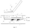
FIG. 6 to FIG. 9 are diagrams of processes of mounting an antenna board and a fastener, whereFIG. 6 is a schematic diagram of a structure existing before the mounting,FIG. 7 is a schematic diagram of a structure with the antenna board mounted in a mounting cavity,FIG. 8 is a schematic diagram of a structure with the fastener mounted in the mounting cavity, andFIG. 9 is a schematic diagram of a structure obtained after the mounting is completed; -
FIG. 10 is a schematic diagram of a structure with an antenna board mounted in a mounting cavity, where an operation portion as a whole is located in the mounting cavity; and -
FIG. 11 is a main view ofFIG. 10 . - Description of reference numerals in
FIG. 1 to FIG. 11 : - 1: middle frame; 11: mounting cavity; 111: upper cavity body; 112: middle cavity body; 113: accommodating groove; 114: slot; 115: limiting protrusion; 116: avoidance space; 12: middle plate; and 13: bezel;
- 2: antenna board; 21: first end; 22: second end; 23: second convex portion; and 24: baffle plate;
- 3: fastener; 31: fastening plate; 311: guiding surface; 32: first convex portion; 33: stopper; and 34: limiting block;
- 4: metal elastomer;
- 51: positioning hole; and 52: positioning protrusion;
- 6: operation portion; and
- 7 : battery compartment.
- Embodiments of the present invention provide an electronic device. The electronic device may be a terminal product, such as a mobile phone, a tablet computer, a wearable device, an in-vehicle device, an augmented reality (augmented reality, AR)/virtual reality (virtual reality, VR) device, a notebook computer, an ultra-mobile personal computer (ultra-mobile personal computer, UMPC), a netbook, or a personal digital assistant (personal digital assistant, PDA). A specific type of the electronic device is not limited in the embodiments of this application.
- The electronic device includes a screen, a rear cover, and a middle frame. The middle frame is located between the screen and the rear cover. As shown in
FIG. 1 , amiddle frame 1 of the electronic device includes amiddle plate 12 and abezel 13. Thebezel 13 circumferentially surrounds an outer edge of themiddle plate 12. Abattery compartment 7 is provided between themiddle plate 12 and the rear cover. Thebattery compartment 7 is configured to house a battery for supplying power to the electronic device. Thebezel 13 is provided with a mountingcavity 11. A depth direction of the mountingcavity 11 is arranged along a thickness direction of the electronic device. The mountingcavity 11 is provided on an end face on a rear side of the middle frame 1 ("rear side" specifically refers to a side facing the rear cover). The mountingcavity 11 is located outside thebattery compartment 7 and is configured to mount anantenna board 2 of the electronic device. - As electronic devices are provided with increasing functions and larger screens, the electronic devices consume power faster. To ensure a battery life for the electronic devices, a larger battery is preferred. Correspondingly, a larger space is also preferred for the
battery compartment 7. Therefore, when the electronic devices have a same volume, themiddle frame 1 is located in a limited space outside thebattery compartment 7, that is, thebezel 13 has a limited width, and an arrangement space of the mountingcavity 11 is limited. As a result, when theantenna board 2 is mounted in the mountingcavity 11, an operation space is limited, and a mounting operation is inconvenient. Therefore, in the embodiments of this application, theantenna board 2 is fastened in the mountingcavity 11 by using afastener 3. This can ensure mounting stability of theantenna board 2 while simplifying the mounting operation, and can further avoid damage to themiddle frame 1 and thebattery compartment 7 in a mounting process. - In the embodiments of this application, as shown in
FIG. 2 , "upper" refers to a side facing an opening along the depth direction of the mountingcavity 11, and correspondingly "lower" refers to a side facing the inside of the mountingcavity 11 along the depth direction of the mountingcavity 11. - As shown in
FIG. 2 andFIG. 3 , inner walls of the mountingcavity 11 each are provided with a limitingprotrusion 115. Two opposite sidewalls of the mountingcavity 11 along a width direction inwardly protrude to form the limitingprotrusions 115, respectively. A spacing between the limitingprotrusions 115 provided on the two sidewalls is less than a width of thefastener 3 and greater than a width of theantenna board 2 that corresponds to a location here. Thefastener 3 can be clamped between an upper end face of theantenna board 2 and the limitingprotrusions 115. In this case, the limitingprotrusions 115 are located above thefastener 3 and restrict thefastener 3 from moving upward, and the limitingprotrusions 115 form a limiting portion for restricting thefastener 3 from moving upward. - During mounting, the
antenna board 2 can directly pass through a gap between the two limitingprotrusions 115 and enter a mounting groove. Then, thefastener 3 is inserted against the upper end face of theantenna board 2 between the upper end face of theantenna board 2 and the limitingprotrusions 115. The operations are convenient. The limitingprotrusions 115 are used to limit theantenna board 2 from two sides along the width direction. This can ensure stability, so that a more balanced acting force is applied to thefastener 3 and the limiting is more stable. - Specific locations for disposing the limiting
protrusions 115 are not limited. As shown inFIG. 2 , the limitingprotrusions 115 are located at one end of the mountingcavity 11, or the limitingprotrusions 115 may be disposed at middle locations in a length direction of the mountingcavity 11. This is not specifically limited. - Surfaces of the limiting
protrusions 115 present smooth structures, to avoid damage to theantenna board 2 caused by scraping theantenna board 2 during mounting. Further, an end of thefastener 3 is further provided with a guidingsurface 311. When thefastener 3 is mounted, thefastener 3 is inserted between the upper end face of theantenna board 2 and the limitingprotrusions 115. The guidingsurface 311 can avoid abrasion during insertion. The guidingsurface 311 may be either an arc surface or an inclined surface. - Certainly, in some embodiments, a limiting groove (not shown in the figure) may be further provided on an inner wall of the mounting cavity, to form the limiting portion for restricting the
fastener 3 from moving upward. After theantenna board 2 is mounted in the mountingcavity 11, thefastener 3 is inserted into the limiting groove. In this case, thefastener 3 can abut against the upper end face of theantenna board 2, and an upper groove wall of the limiting groove can restrict thefastener 3 from moving upward, thereby ensuring location stability of theantenna board 2. Specifically, the limiting groove may be disposed on each of the two sidewalls of the mountingcavity 11 along the width direction, or may be disposed on an inner wall at one end of the mountingcavity 11. The limiting groove is used to limit thefastener 3, and the limiting groove does not occupy a space in the mountingcavity 11, to facilitate the mounting operation of theantenna board 2. - As shown in
FIG. 2 andFIG. 3 , aslot 114 is further disposed on an inner wall of the mountingcavity 11. Theslot 114 is disposed at one end of the mountingcavity 11. Theantenna board 2 is a strip-shaped structure. Two ends of theantenna board 2 along its length direction are respectively afirst end 21 and asecond end 22. During mounting, thefirst end 21 can be inserted into theslot 114, and an upper sidewall of theslot 114 can limit thefirst end 21, to prevent thefirst end 21 from moving upward along the depth direction of the mountingcavity 11. Thefastener 3 can be clamped between the upper end face of theantenna board 2 and the limitingprotrusions 115. In this case, the limitingprotrusions 115 are located above thefastener 3 and restrict thefastener 3 from moving upward, and thefastener 3 restricts theantenna board 2 from moving upward. Theantenna board 2 is limited by using both theslot 114 and thefastener 3, to prevent theantenna board 2 from moving upward, and further ensure that theantenna board 2 is stably located in the mountingcavity 11. - As shown in
FIG. 3 , a lower end face of theantenna board 2 is further provided with ametal elastomer 4. Themetal elastomer 4 can be clamped between theantenna board 2 and themiddle frame 1 and is configured to implement electrical connection. A bottom of the mountingcavity 11 is further provided with anaccommodating groove 113. After theantenna board 2 is mounted in the mountingcavity 11, themetal elastomer 4 can be located in theaccommodating groove 113, the limitingprotrusions 115 can be pressed against theantenna board 2 from above, theantenna board 2 downwardly compresses themetal elastomer 4, and themetal elastomer 4 in a compressed state can provide theantenna board 2 with an upward elastic support force. In other words, in a mounting state, thefastener 3 and themetal elastomer 4 can respectively act on theantenna board 2 from the end faces on upper and lower sides, so that a location of theantenna board 2 is stable. In addition, as themetal elastomer 4 can provide an elastic acting force to theantenna board 2, a case of crushing theantenna board 2 is avoided while stability is ensured, and further precision requirements on the limitingprotrusions 115 and thefastener 3 can be reduced. - The
antenna board 2 mounted in the mountingcavity 11 can be fastened by using thefastener 3 and the limitingprotrusions 115. The limitingprotrusions 115 are fixedly provided on the inner walls of the mountingcavity 11. The limitingprotrusions 115 and the mountingcavity 11 are integrally formed, or may be fastened by soldering or in another manner before factory delivery. During specific mounting, after theantenna board 2 is mounted in the mountingcavity 11, it is only required to insert thefastener 3 between theantenna board 2 and the mountingcavity 11, without using a large complex operation tool (such as a screwdriver). The mounting operation can be simplified, and no damage is caused to the inner walls of the mountingcavity 11 and even theadjacent battery compartment 7. A quantity of thefasteners 3 is not limited. Specifically, theantenna board 2 may be limited by using twofasteners 3, or theantenna board 2 may be limited by using onefastener 3. Specifically, the quantity of thefasteners 3 may be set based on a length of the antenna board, a length of each fastener, and the like. - In the embodiments of this application, alternatively, no
slot 114 may be disposed in the mountingcavity 11, and theantenna board 2 may be fastened only by using thefastener 3 and the limiting portion (the limitingprotrusions 115 or the limiting groove). When thefastener 3 and theslot 114 are used to limit theantenna board 2, only onefastener 3 needs to be disposed to ensure mounting stability of theantenna board 2 and to further simplify an overall structure while simplifying the mounting operation. - The mounting
cavity 11 is inwardly provided with the limitingprotrusions 115 respectively on the two opposite sidewalls along the width direction, the spacing between the two limitingprotrusions 115 is less than the width of thefastener 3 and greater than the width of theantenna board 2 that corresponds to a location here, thereby forming the limiting portion above. During mounting, theantenna board 2 can directly pass through the gap between the two limitingprotrusions 115 and enter the mounting groove. Then, thefastener 3 is inserted against the upper end face of theantenna board 2 between the upper end face of theantenna board 2 and the limitingprotrusions 115. The operations are convenient. The limitingprotrusions 115 are used to limit theantenna board 2 from the two sides along the width direction. This can ensure stability, so that a more balanced acting force is applied to thefastener 3 and the limiting is more stable. - As shown in
FIG. 2 , the space in the mountingcavity 11 sequentially includes anupper cavity body 111 and amiddle cavity body 112 from outside in. A length of themiddle cavity body 112 adapts to the length of theantenna board 2. Themiddle cavity body 112 is provided with the foregoingslot 114 at one end along its own length direction. Theupper cavity body 111 is provided with the limitingprotrusions 115. Themiddle cavity body 112 is configured to accommodate theantenna board 2. Theupper cavity body 111 is located above themiddle cavity body 112. In addition, theupper cavity body 111 outwardly extends relative to themiddle cavity body 112 by one segment at one end away from theslot 114. This extending portion forms an avoidance space. A bottom of themiddle cavity body 112 is provided with theaccommodating groove 113. - To ensure location stability for the
antenna board 2 after theantenna board 2 is mounted in themiddle cavity body 112, the length of themiddle cavity body 112 is not much greater than the length of theantenna board 2. Therefore, to ensure that theantenna board 2 can be smoothly mounted in themiddle cavity body 112 and fit into theslot 114, theantenna board 2 inclinedly enters the mountingcavity 11 during mounting. Specifically, thefirst end 21 downwardly enters themiddle cavity body 112 of the mountingcavity 11 and reaches an opening location of theslot 114. In this case, thesecond end 22 is inclined upward and located in the avoidance space of theupper cavity body 111, and then theantenna board 2 is pushed, so that thefirst end 21 is inserted into theslot 114. At this time, theantenna board 2 is still inclined and thesecond end 22 is located in theupper cavity body 111. Afterwards, thesecond end 22 is pushed downward, so that thesecond end 22 fully enters themiddle cavity body 112. Themetal elastomer 4 on the lower end face of theantenna board 2 can just fall into theaccommodating groove 113. Subsequently, thefastener 3 is mounted. Disposing theavoidance space 116 facilitates the mounting operation of theantenna board 2. - As shown in
FIG. 3 to FIG. 5 , a firstconvex portion 32 upwardly protrudes from thefastener 3, the firstconvex portion 32 forms a first limiting structure, a secondconvex portion 23 upwardly protrudes from the upper end face of theantenna board 2, and the secondconvex portion 23 forms a second limiting structure. In the mounting state, the firstconvex portion 32 is located between the secondconvex portion 23 and the limitingprotrusions 115. In other words, the secondconvex portion 23 and the limitingprotrusions 115 can tightly clamp the firstconvex portion 32 respectively from both sides along the length direction. Such arrangement can restrict the firstconvex portion 32 from moving towards both sides along the length direction. A case that is caused by shaking of the electronic device and the like and in which thefastener 3 slides relative to the limitingprotrusions 115 along the length direction of the mountingcavity 11 and is detached from the limiting portion can be avoided in a use process. This can ensure that thefastener 3 can be stably clamped between the limiting portion and the upper end face of theantenna board 2, and further ensure that thefastener 3 has a stable effect on theantenna board 2. - In other words, the first limiting structure is provided on the
fastener 3, and the second limiting structure is provided on theantenna board 2. In the mounting state, the two limiting structures cooperate with each other for limiting, to restrict thefastener 3 from moving along the length direction of the mountingcavity 11, thereby ensuring stability of thefastener 3. - Further, as shown in
FIG. 4 , thefastener 3 includes afastening plate 31. Thefastening plate 31 partially arches upward, and an arched portion forms the firstconvex portion 32 protruding upward. Certainly, the firstconvex portion 32 may be formed by partially bending thefastening plate 31 or formed by machining. Alternatively, thefastening plate 31 may be provided as a flat plate structure, and a convex structure may be fastened on an upper end face at one end of thefastening plate 31 that faces the firstconvex portion 32, to form the firstconvex portion 32. When the firstconvex portion 32 is formed by the partial arching, the overall structure can be simplified and an overall weight can be reduced. - In the embodiments of this application, the
fastener 3 is a plastic member. Thefastener 3 may be integrally injection-molded, may be provided as a metal member, or the like. The integrally injection-molded plastic member can simplify the overall structure and a processing process. - As shown in
FIG. 3 andFIG. 4 , an end of the firstconvex portion 32 is further provided with astopper 33. Thestopper 33 is configured to abut against the secondconvex portion 23. In the mounting state, a lower end of thestopper 33 can abut against the upper end face of theantenna board 2, to avoid a case that a gap exists between the lower end of thestopper 33 and the upper end face of theantenna board 2 and limiting cannot be implemented due to entry of the secondconvex portion 23 into the gap when the secondconvex portion 23 abuts against thestopper 33. In addition, an upper end of thestopper 33 is further provided with a limitingblock 34. The limitingblock 34 is disposed on a side that faces the secondconvex portion 23. When the secondconvex portion 23 abuts against thestopper 33, the limitingblock 34 can limit an abutment location of the secondconvex portion 23 from above, so as to limit the secondconvex portion 23 to between the upper end face of theantenna board 2 and the limitingblock 34, thereby ensuring a stable limiting effect. - As shown in
FIG. 3 andFIG. 4 , thefastener 3 is further provided with anoperation portion 6. Theoperation portion 6 is fastened to thefastener 3, and theoperation portion 6 has a long length. During mounting, theoperation portion 6 is operated to place thefastener 3 into the mountingcavity 11, and theoperation portion 6 is pushed, so that thefastener 3 is inserted between the upper end face of theantenna board 2 and the limitingprotrusions 115. The operations are convenient. Theoperation portion 6 extends out of the mountingcavity 11 due to its long length. In this way, a sufficient space for manual operations is provided. Specifically, theoperation portion 6 is detachable from thefastener 3. Therefore, after the mounting is completed, theoperation portion 6 may be detached from thefastener 3 and then removed, to avoid impact of theoperation portion 6 on subsequent mounting. - Specifically, a manner of connection between the
fastener 3 and theoperation portion 6 is not limited in the embodiments of this application. For example, thefastener 3 may be detachably connected to theoperation portion 6 by using threads or the like, or thefastener 3 and theoperation portion 6 may be provided as an integral structure, while connection strength at a connection joint between thefastener 3 and theoperation portion 6 is reduced (for example, a cross-sectional area of the connection joint is reduced). After mounting of thefastener 3 is completed, the connection between theoperation portion 6 and thefastener 3 may be broken directly in a manner such as rotating or bending theoperation portion 6 relative to thefastener 3, and then theoperation portion 6 can be removed. The operations are convenient. - As a mounting space is small and a volume of the
fastener 3 is also small, operations are inconvenient if a mounting person holds thefastener 3 and inserts thefastener 3 between the upper end face of theantenna board 2 and the limitingprotrusions 115 only by hands. In contrast, when the mounting is performed by using theoperation portion 6, operations for picking, placing, and mounting thefastener 3 are convenient. - A structure of the second
convex portion 23 is not limited. To further prevent the secondconvex portion 23 from entering the gap between the lower end of thestopper 33 and the upper end face of theantenna board 2, the secondconvex portion 23 may be a bump fixedly provided on the upper end face of theantenna board 2. The bump may have a specific height, for example, a top end of the bump is substantially corresponding to a location at or above the middle of thestopper 33 and is below the limitingblock 34. Alternatively, as shown inFIG. 3 andFIG. 5 , the upper end face of theantenna board 2 is further fixedly provided with abaffle plate 24, and thebaffle plate 24 is upwardly bent towards one end of the firstconvex portion 32 to form the secondconvex portion 23. The secondconvex portion 23 is a structure tilted on the upper end face of theantenna board 2. The secondconvex portion 23 has a specific height to ensure that the secondconvex portion 23 can abut against a middle location of thestopper 33. This further ensures that the secondconvex portion 23 does not enter the gap between the lower end of thestopper 33 and the upper end face of theantenna board 2, thereby ensuring a stable limiting effect. When the secondconvex portion 23 is formed by bending thebaffle plate 24, the overall structure and a molding process can be further simplified. - The connection and fastening between the bump and the upper end face of the
antenna board 2 and between thebaffle plate 24 and the upper end face of theantenna board 2 are completed outside the mountingcavity 11. Therefore, the connection and fastening between the bump and the upper end face of theantenna board 2 and between thebaffle plate 24 and the upper end face of theantenna board 2 are not limited, for example, the fastening may be implemented by soldering or a fastener. - A specific mounting process of the
antenna board 2 is shown inFIG. 6 to FIG. 9 . InFIG. 6 , neither theantenna board 2 nor thefastener 3 is mounted. As shown inFIG. 7 , theantenna board 2 is first mounted in themiddle cavity body 112 of the mountingcavity 11. Then, as shown inFIG. 8 , thefastening plate 31 of thefastener 3 is inserted between the upper end face of theantenna board 2 and the limitingprotrusions 115 by using theoperation portion 6, the firstconvex portion 32 is located between the secondconvex portion 23 and the limitingprotrusions 115, and a location of theantenna board 2 is stable. Finally, theoperation portion 6 is removed. A final product structure is shown inFIG. 9 . - In the embodiments of this application, a specific structure of the fastener is not limited.
FIG. 10 and FIG. 11 show afastener 3 in another embodiment. Thefastener 3 is provided with apositioning protrusion 52. Thepositioning protrusion 52 forms the first limiting structure. Theantenna board 2 is provided with apositioning hole 51. Thepositioning hole 51 forms the second limiting structure. After mounting, when thefastener 3 is clamped between the limiting portion and the upper end face of theantenna board 2, thepositioning protrusion 52 can be inserted into thepositioning hole 51, thereby limiting thefastener 3 and theantenna board 2 along the length direction. Cooperation between the positioningprotrusion 52 and thepositioning hole 52 is similar to the cooperation between the firstconvex portion 32 and the secondconvex portion 23, and detachment between thefastener 3 and the limitingprotrusions 115 that is caused by location movement of thefastener 3 can be prevented. When thepositioning hole 51 cooperates with thepositioning protrusion 52 to implement positioning, the overall structure can be simplified while a stable limiting effect can be ensured. - Specifically, a specific structure of the
positioning protrusion 52 is not limited. For example, a protrusion structure may be formed by downwardly stamping thefastener 3, or a protrusion structure may be integrally formed or additionally fastened on a lower end face of thefastener 3. Certainly, in the embodiments of this application, alternatively, thefastener 3 may be provided with apositioning hole 51, and the upper end face of theantenna board 2 may be provided with apositioning protrusion 52. After thefastener 3 is mounted, thepositioning protrusion 52 can be inserted into thepositioning hole 51 to implement positioning cooperation. - After the
positioning protrusion 52 is inserted into thepositioning hole 51, a location of thefastener 3 and that of theantenna board 2 are relatively fixed along the length direction. Since theantenna board 2 is mounted in themiddle cavity body 112, theantenna board 2 has a stable location along its length direction. Therefore, when the relative locations of thefastener 3 and theantenna board 2 are fixed, it can be ensured that thefastening plate 31 is not detached from the limitingprotrusions 115 due to location movement. - The
operation portion 6 obtained in the foregoing embodiment has a long length. After thefastener 3 is mounted, theoperation portion 6 partially extends out of the mountingcavity 11. Theoperation portion 6 is detachable from thefastener 3. After the mounting is completed, theoperation portion 6 can be removed.FIG. 10 and FIG. 11 show anoperation portion 6 in another embodiment. After thefastener 3 is mounted, theoperation portion 6 as a whole is located in the mountingcavity 11, and does not extend out of the mountingcavity 11. Therefore, theoperation portion 6 does not affect subsequent mounting or use. In other words, theoperation portion 6 does not need to be removed after the mounting is completed. Specifically, during mounting, a mounting person may clamp theoperation portion 6 by using tweezers, a clamp, or the like, and act on theoperation portion 6 from the outside of the mountingcavity 11, so that thefastener 3 is inserted between theantenna board 2 and the limitingprotrusions 115. The operations are convenient. Specifically, theoperation portion 6 may be formed by bending an end of thefastener 3, or theoperation portion 6 may be fastened to thefastener 3 by soldering or the like. - In this specification, principles and implementations of the present invention are described by using specific examples. The descriptions of the foregoing embodiments are merely intended to help understand the method and the core idea of the present invention. It should be noted that, a person of ordinary skill in the art can further make some improvements and modifications to the present invention without departing from the principles of the present invention, and the improvements and modifications shall fall within the protection scope of the present invention.
Claims (15)
- An electronic device, comprising a middle frame (1), an antenna board (2), and a fastener (3);the middle frame (1) is provided with a mounting cavity (11), and an inner wall of the mounting cavity (11) is provided with a limiting portion; andthe antenna board (2) is placed in the mounting cavity (11), and the fastener (3) is capable of being clamped between the limiting portion and an upper end face of the antenna board (2), to restrict the antenna board (2) from moving upward along a depth direction of the mounting cavity (11).
- The electronic device according to claim 1, wherein the mounting cavity (11) is inwardly provided with a limiting protrusion (115) on each of two sidewalls along a width direction, a spacing between the limiting protrusions (115) disposed on the two sidewalls is less than a width of the fastener (3), and the limiting protrusions (115) form the limiting portion.
- The electronic device according to claim 1, wherein the limiting portion is a limiting groove disposed on the inner wall of the mounting cavity (11), and the fastener (3) is capable of being inserted into the limiting groove and abutting against the upper end face of the antenna board (2).
- The electronic device according to any one of claims 1 to 3, wherein a slot (114) is further disposed on an inner wall at one end of the mounting cavity (11) along a length direction of the mounting cavity (11), a first end (21) of the antenna board (2) along a length direction of the antenna board (2) is capable of being inserted into the slot (114), and an upper sidewall of the slot (114) is capable of restricting the antenna board (2) from moving upward.
- The electronic device according to claim 4, wherein the mounting cavity (11) comprises an upper cavity body (111) and a middle cavity body (112) from top to bottom; and
the middle cavity body (112) is provided with the slot (114), and the upper cavity body (111) outwardly extends away from one end of the slot (114) and forms an avoidance space (116). - The electronic device according to claim 5, wherein a bottom of the middle cavity body (112) is further provided with an accommodating groove (113), a lower end face of the antenna board (2) is further provided with a metal elastomer (4) for connecting to the middle frame (1), and when the antenna board (2) is mounted in the middle cavity body (112), the metal elastomer (4) is located in the accommodating groove (113).
- The electronic device according to any one of claims 1 to 6, wherein the fastener (3) is provided with a first limiting structure, the antenna board (2) is provided with a second limiting structure, and when the fastener (3) abuts against the upper end face of the antenna board (2), the first limiting structure and the second limiting structure are capable of cooperating with each other to restrict the fastener (3) from moving and being detached from the limiting portion.
- The electronic device according to claim 7, wherein the first limiting structure is a first convex portion (32) upwardly protruding from the fastener (3), the second limiting structure is a second convex portion (23) upwardly protruding from the upper end face of the antenna board (2), and the first convex portion (32) is located between the second convex portion (23) and the limiting portion.
- The electronic device according to claim 8, wherein the fastener (3) comprises a fastening plate (31), and the fastening plate (31) partially arches upward and forms the first convex portion (32).
- The electronic device according to claim 9, wherein an end of the first convex portion (32) is further provided with a stopper (33) for abutting against the second convex portion (23), a bottom of the stopper (33) is capable of abutting against the upper end face of the antenna board (2), and a limiting block (34) is further disposed on a side that is of an upper portion of the stopper (33) and that faces the second convex portion (23).
- The electronic device according to any one of claims 8 to 10, wherein the upper end face of the antenna board (2) is fixedly provided with a baffle plate (24), and the baffle plate (24) is upwardly bent towards one end of the first convex portion (32) and forms the second convex portion (23).
- The electronic device according to claim 7, wherein one of the first limiting structure and the second limiting structure is a positioning hole (51) and the other is a positioning protrusion (52), and when the fastener (3) is clamped between the limiting portion and the upper end face of the antenna board (2), the positioning protrusion (52) is capable of being inserted into the positioning hole (51).
- The electronic device according to any one of claims 1 to 12, wherein the fastener (3) is further provided with an operation portion (6).
- The electronic device according to claim 13, wherein the operation portion (6) is capable of being detached from the fastener (3).
- The electronic device according to claim 13, wherein the operation portion (6) is formed by bending an end of the fastener (3), and the operation portion (6) is located in the mounting cavity (11).
Applications Claiming Priority (2)
| Application Number | Priority Date | Filing Date | Title |
|---|---|---|---|
| CN202111045127.1A CN115000674B (en) | 2021-09-07 | 2021-09-07 | Electronic equipment |
| PCT/CN2022/114777 WO2023035962A1 (en) | 2021-09-07 | 2022-08-25 | Electronic device |
Publications (3)
| Publication Number | Publication Date |
|---|---|
| EP4184711A1 true EP4184711A1 (en) | 2023-05-24 |
| EP4184711A4 EP4184711A4 (en) | 2024-06-26 |
| EP4184711B1 EP4184711B1 (en) | 2025-04-02 |
Family
ID=83017988
Family Applications (1)
| Application Number | Title | Priority Date | Filing Date |
|---|---|---|---|
| EP22856860.6A Active EP4184711B1 (en) | 2021-09-07 | 2022-08-25 | Electronic device |
Country Status (4)
| Country | Link |
|---|---|
| US (1) | US12212038B2 (en) |
| EP (1) | EP4184711B1 (en) |
| CN (2) | CN115000674B (en) |
| WO (1) | WO2023035962A1 (en) |
Family Cites Families (28)
| Publication number | Priority date | Publication date | Assignee | Title |
|---|---|---|---|---|
| EP1764860A1 (en) * | 2001-04-11 | 2007-03-21 | LG Electronics Inc. | Internal display-mounted antenna for mobile electronic equipment and mobile electronic equipment incorporating same |
| US8472203B2 (en) * | 2007-09-04 | 2013-06-25 | Apple Inc. | Assembly of a handheld electronic device |
| US7768472B2 (en) | 2008-03-14 | 2010-08-03 | Sony Corporation | Unobstrusive placement of wireless antenna for CE devices |
| US8174452B2 (en) * | 2008-09-25 | 2012-05-08 | Apple Inc. | Cavity antenna for wireless electronic devices |
| US8020824B2 (en) * | 2009-08-04 | 2011-09-20 | Jonsa Technologies Co., Ltd. | Adjustment assembly for a satellite antenna |
| JP5287833B2 (en) * | 2010-11-15 | 2013-09-11 | 三菱電機株式会社 | High frequency module and array antenna apparatus using the same |
| US9225071B2 (en) * | 2012-04-06 | 2015-12-29 | Ubiquiti Networks, Inc. | Antenna assembly for long-range high-speed wireless communications |
| CN202616397U (en) | 2012-05-11 | 2012-12-19 | 惠州Tcl移动通信有限公司 | Mobile phone and antenna structure thereof |
| KR101973127B1 (en) * | 2012-11-13 | 2019-04-26 | 삼성전자주식회사 | Antenna apparatus for portable terminal |
| EP3041706B1 (en) * | 2013-10-02 | 2021-07-07 | Lt350, Llc | Solar canopy with integral storage compartment to receive high capacity batteries |
| CN204090364U (en) * | 2014-08-20 | 2015-01-07 | 深圳Tcl新技术有限公司 | electronic device with antenna |
| CN205104599U (en) | 2015-09-16 | 2016-03-23 | 深圳市天玑显示技术有限公司 | Structure of fixed FPC antenna |
| CN206472427U (en) | 2016-09-28 | 2017-09-05 | 华为技术有限公司 | Radiating structure for electronic equipment and electronic equipment |
| US10547097B2 (en) * | 2017-05-04 | 2020-01-28 | Kymeta Corporation | Antenna aperture with clamping mechanism |
| CN107689483A (en) * | 2017-08-09 | 2018-02-13 | 捷开通讯(深圳)有限公司 | Antenna module and electronic equipment |
| CN107995333B (en) * | 2017-12-01 | 2019-12-31 | Oppo广东移动通信有限公司 | Middle frame, middle frame components and electronic equipment |
| CN108039565B (en) * | 2018-01-29 | 2020-05-08 | Oppo广东移动通信有限公司 | Middle frame assembly, electronic equipment and assembling method thereof |
| CN108336475B (en) * | 2018-01-29 | 2020-01-17 | Oppo广东移动通信有限公司 | A middle frame assembly, electronic equipment and assembling method thereof |
| CN108039556A (en) * | 2018-01-30 | 2018-05-15 | 上海康斐信息技术有限公司 | A kind of antenna holder and middle frame structure |
| CN108682937B (en) * | 2018-05-04 | 2021-03-02 | Oppo广东移动通信有限公司 | Shell assembly, antenna assembly and electronic equipment |
| CN108541132A (en) * | 2018-06-08 | 2018-09-14 | 扬州市玄裕电子有限公司 | A kind of silver-plated single side Wire Antennas plate of large scale |
| CN109546295B (en) * | 2018-11-21 | 2021-06-04 | Oppo广东移动通信有限公司 | electronic device |
| US11056762B2 (en) * | 2019-01-08 | 2021-07-06 | Jonsa Technologies Co., Ltd. | Adjustable antenna mount |
| CN110970248B (en) * | 2019-11-26 | 2021-09-10 | 荣耀终端有限公司 | Electronic device |
| US11349193B2 (en) * | 2019-12-05 | 2022-05-31 | Dell Products, Lp | System and method for a hinge cavity electric field trap using heat exhaust vent grill |
| CN112291154A (en) * | 2020-09-30 | 2021-01-29 | 深圳数联天下智能科技有限公司 | Router |
| CN112421209B (en) * | 2020-12-11 | 2023-12-12 | 维沃移动通信有限公司 | Electronic equipment |
| CN113178681B (en) * | 2021-04-15 | 2023-01-24 | 维沃移动通信有限公司 | Electronic device |
-
2021
- 2021-09-07 CN CN202111045127.1A patent/CN115000674B/en active Active
- 2021-09-07 CN CN202310442780.4A patent/CN116646707B/en active Active
-
2022
- 2022-08-25 WO PCT/CN2022/114777 patent/WO2023035962A1/en not_active Ceased
- 2022-08-25 US US18/023,877 patent/US12212038B2/en active Active
- 2022-08-25 EP EP22856860.6A patent/EP4184711B1/en active Active
Also Published As
| Publication number | Publication date |
|---|---|
| WO2023035962A1 (en) | 2023-03-16 |
| CN116646707B (en) | 2024-05-14 |
| CN115000674B (en) | 2023-04-28 |
| US20240178545A1 (en) | 2024-05-30 |
| US12212038B2 (en) | 2025-01-28 |
| CN115000674A (en) | 2022-09-02 |
| CN116646707A (en) | 2023-08-25 |
| EP4184711B1 (en) | 2025-04-02 |
| EP4184711A4 (en) | 2024-06-26 |
Similar Documents
| Publication | Publication Date | Title |
|---|---|---|
| US7660560B2 (en) | Battery cover latching assembly for portable electronic device | |
| CN104765416B (en) | Attachment and detachment device for protective cover and electronic device | |
| EP2634833A1 (en) | Battery pack lock structure and electronic apparatus | |
| US8254091B2 (en) | Portable electronic device | |
| US7579107B2 (en) | Portable electronic device employing battery | |
| US20070003827A1 (en) | Battery cover latching assembly for portable electronic device | |
| US20070087263A1 (en) | Battery cover latching assembly for portable electronic device | |
| CN101673812A (en) | Battery cover component | |
| US20100075212A1 (en) | Battery cover latch mechanism and portable electronic device using same | |
| CN110970248B (en) | Electronic device | |
| EP4391505A1 (en) | Terminal device | |
| US6658271B1 (en) | Combination touch pad and cell of cellular phone and the producing method therefor | |
| EP4184711B1 (en) | Electronic device | |
| US8338013B2 (en) | Electronic device | |
| US20040203267A1 (en) | Self-alignment structure | |
| US8705241B2 (en) | Electronic device | |
| US20100151304A1 (en) | Battery cover latching assembly | |
| US8165650B2 (en) | Portable electronic device | |
| JP2013042281A (en) | Portable terminal | |
| US10591961B2 (en) | Terminal device | |
| HK40077906B (en) | Electronic device | |
| US7957136B2 (en) | Electronic apparatus | |
| US7995338B2 (en) | Cover latch mechanism and electronic device using the same | |
| HK40077906A (en) | Electronic device | |
| CN214627045U (en) | Mobile phone frame structure for installing screen |
Legal Events
| Date | Code | Title | Description |
|---|---|---|---|
| STAA | Information on the status of an ep patent application or granted ep patent |
Free format text: STATUS: UNKNOWN |
|
| STAA | Information on the status of an ep patent application or granted ep patent |
Free format text: STATUS: THE INTERNATIONAL PUBLICATION HAS BEEN MADE |
|
| PUAI | Public reference made under article 153(3) epc to a published international application that has entered the european phase |
Free format text: ORIGINAL CODE: 0009012 |
|
| STAA | Information on the status of an ep patent application or granted ep patent |
Free format text: STATUS: REQUEST FOR EXAMINATION WAS MADE |
|
| 17P | Request for examination filed |
Effective date: 20230220 |
|
| AK | Designated contracting states |
Kind code of ref document: A1 Designated state(s): AL AT BE BG CH CY CZ DE DK EE ES FI FR GB GR HR HU IE IS IT LI LT LU LV MC MK MT NL NO PL PT RO RS SE SI SK SM TR |
|
| A4 | Supplementary search report drawn up and despatched |
Effective date: 20240523 |
|
| RIC1 | Information provided on ipc code assigned before grant |
Ipc: H01Q 1/38 20060101ALI20240517BHEP Ipc: H01Q 1/12 20060101ALI20240517BHEP Ipc: H01Q 1/24 20060101ALI20240517BHEP Ipc: H01Q 1/22 20060101AFI20240517BHEP |
|
| GRAP | Despatch of communication of intention to grant a patent |
Free format text: ORIGINAL CODE: EPIDOSNIGR1 |
|
| STAA | Information on the status of an ep patent application or granted ep patent |
Free format text: STATUS: GRANT OF PATENT IS INTENDED |
|
| DAV | Request for validation of the european patent (deleted) | ||
| DAX | Request for extension of the european patent (deleted) | ||
| INTG | Intention to grant announced |
Effective date: 20241122 |
|
| GRAS | Grant fee paid |
Free format text: ORIGINAL CODE: EPIDOSNIGR3 |
|
| GRAA | (expected) grant |
Free format text: ORIGINAL CODE: 0009210 |
|
| STAA | Information on the status of an ep patent application or granted ep patent |
Free format text: STATUS: THE PATENT HAS BEEN GRANTED |
|
| AK | Designated contracting states |
Kind code of ref document: B1 Designated state(s): AL AT BE BG CH CY CZ DE DK EE ES FI FR GB GR HR HU IE IS IT LI LT LU LV MC MK MT NL NO PL PT RO RS SE SI SK SM TR |
|
| REG | Reference to a national code |
Ref country code: GB Ref legal event code: FG4D |
|
| REG | Reference to a national code |
Ref country code: CH Ref legal event code: EP |
|
| REG | Reference to a national code |
Ref country code: IE Ref legal event code: FG4D |
|
| REG | Reference to a national code |
Ref country code: DE Ref legal event code: R096 Ref document number: 602022012710 Country of ref document: DE |
|
| REG | Reference to a national code |
Ref country code: NL Ref legal event code: FP |
|
| PGFP | Annual fee paid to national office [announced via postgrant information from national office to epo] |
Ref country code: NL Payment date: 20250704 Year of fee payment: 4 |
|
| REG | Reference to a national code |
Ref country code: AT Ref legal event code: MK05 Ref document number: 1782249 Country of ref document: AT Kind code of ref document: T Effective date: 20250402 |
|
| PG25 | Lapsed in a contracting state [announced via postgrant information from national office to epo] |
Ref country code: FI Free format text: LAPSE BECAUSE OF FAILURE TO SUBMIT A TRANSLATION OF THE DESCRIPTION OR TO PAY THE FEE WITHIN THE PRESCRIBED TIME-LIMIT Effective date: 20250402 Ref country code: ES Free format text: LAPSE BECAUSE OF FAILURE TO SUBMIT A TRANSLATION OF THE DESCRIPTION OR TO PAY THE FEE WITHIN THE PRESCRIBED TIME-LIMIT Effective date: 20250402 Ref country code: PT Free format text: LAPSE BECAUSE OF FAILURE TO SUBMIT A TRANSLATION OF THE DESCRIPTION OR TO PAY THE FEE WITHIN THE PRESCRIBED TIME-LIMIT Effective date: 20250804 |
|
| PGFP | Annual fee paid to national office [announced via postgrant information from national office to epo] |
Ref country code: DE Payment date: 20250702 Year of fee payment: 4 |
|
| REG | Reference to a national code |
Ref country code: LT Ref legal event code: MG9D |
|
| PG25 | Lapsed in a contracting state [announced via postgrant information from national office to epo] |
Ref country code: NO Free format text: LAPSE BECAUSE OF FAILURE TO SUBMIT A TRANSLATION OF THE DESCRIPTION OR TO PAY THE FEE WITHIN THE PRESCRIBED TIME-LIMIT Effective date: 20250702 Ref country code: GR Free format text: LAPSE BECAUSE OF FAILURE TO SUBMIT A TRANSLATION OF THE DESCRIPTION OR TO PAY THE FEE WITHIN THE PRESCRIBED TIME-LIMIT Effective date: 20250703 |
|
| PG25 | Lapsed in a contracting state [announced via postgrant information from national office to epo] |
Ref country code: PL Free format text: LAPSE BECAUSE OF FAILURE TO SUBMIT A TRANSLATION OF THE DESCRIPTION OR TO PAY THE FEE WITHIN THE PRESCRIBED TIME-LIMIT Effective date: 20250402 |
|
| PG25 | Lapsed in a contracting state [announced via postgrant information from national office to epo] |
Ref country code: BG Free format text: LAPSE BECAUSE OF FAILURE TO SUBMIT A TRANSLATION OF THE DESCRIPTION OR TO PAY THE FEE WITHIN THE PRESCRIBED TIME-LIMIT Effective date: 20250402 |
|
| PG25 | Lapsed in a contracting state [announced via postgrant information from national office to epo] |
Ref country code: HR Free format text: LAPSE BECAUSE OF FAILURE TO SUBMIT A TRANSLATION OF THE DESCRIPTION OR TO PAY THE FEE WITHIN THE PRESCRIBED TIME-LIMIT Effective date: 20250402 |
|
| PG25 | Lapsed in a contracting state [announced via postgrant information from national office to epo] |
Ref country code: AT Free format text: LAPSE BECAUSE OF FAILURE TO SUBMIT A TRANSLATION OF THE DESCRIPTION OR TO PAY THE FEE WITHIN THE PRESCRIBED TIME-LIMIT Effective date: 20250402 |
|
| PG25 | Lapsed in a contracting state [announced via postgrant information from national office to epo] |
Ref country code: RS Free format text: LAPSE BECAUSE OF FAILURE TO SUBMIT A TRANSLATION OF THE DESCRIPTION OR TO PAY THE FEE WITHIN THE PRESCRIBED TIME-LIMIT Effective date: 20250702 |
|
| PG25 | Lapsed in a contracting state [announced via postgrant information from national office to epo] |
Ref country code: IS Free format text: LAPSE BECAUSE OF FAILURE TO SUBMIT A TRANSLATION OF THE DESCRIPTION OR TO PAY THE FEE WITHIN THE PRESCRIBED TIME-LIMIT Effective date: 20250802 |
|
| PG25 | Lapsed in a contracting state [announced via postgrant information from national office to epo] |
Ref country code: LV Free format text: LAPSE BECAUSE OF FAILURE TO SUBMIT A TRANSLATION OF THE DESCRIPTION OR TO PAY THE FEE WITHIN THE PRESCRIBED TIME-LIMIT Effective date: 20250402 |
|
| REG | Reference to a national code |
Ref country code: DE Ref legal event code: R097 Ref document number: 602022012710 Country of ref document: DE |
|
| PG25 | Lapsed in a contracting state [announced via postgrant information from national office to epo] |
Ref country code: DK Free format text: LAPSE BECAUSE OF FAILURE TO SUBMIT A TRANSLATION OF THE DESCRIPTION OR TO PAY THE FEE WITHIN THE PRESCRIBED TIME-LIMIT Effective date: 20250402 Ref country code: SM Free format text: LAPSE BECAUSE OF FAILURE TO SUBMIT A TRANSLATION OF THE DESCRIPTION OR TO PAY THE FEE WITHIN THE PRESCRIBED TIME-LIMIT Effective date: 20250402 |
|
| PG25 | Lapsed in a contracting state [announced via postgrant information from national office to epo] |
Ref country code: CZ Free format text: LAPSE BECAUSE OF FAILURE TO SUBMIT A TRANSLATION OF THE DESCRIPTION OR TO PAY THE FEE WITHIN THE PRESCRIBED TIME-LIMIT Effective date: 20250402 |
|
| PG25 | Lapsed in a contracting state [announced via postgrant information from national office to epo] |
Ref country code: EE Free format text: LAPSE BECAUSE OF FAILURE TO SUBMIT A TRANSLATION OF THE DESCRIPTION OR TO PAY THE FEE WITHIN THE PRESCRIBED TIME-LIMIT Effective date: 20250402 |
|
| PG25 | Lapsed in a contracting state [announced via postgrant information from national office to epo] |
Ref country code: SK Free format text: LAPSE BECAUSE OF FAILURE TO SUBMIT A TRANSLATION OF THE DESCRIPTION OR TO PAY THE FEE WITHIN THE PRESCRIBED TIME-LIMIT Effective date: 20250402 |
|
| PG25 | Lapsed in a contracting state [announced via postgrant information from national office to epo] |
Ref country code: IT Free format text: LAPSE BECAUSE OF FAILURE TO SUBMIT A TRANSLATION OF THE DESCRIPTION OR TO PAY THE FEE WITHIN THE PRESCRIBED TIME-LIMIT Effective date: 20250402 |
|
| PLBE | No opposition filed within time limit |
Free format text: ORIGINAL CODE: 0009261 |
|
| STAA | Information on the status of an ep patent application or granted ep patent |
Free format text: STATUS: NO OPPOSITION FILED WITHIN TIME LIMIT |
|
| REG | Reference to a national code |
Ref country code: CH Ref legal event code: L10 Free format text: ST27 STATUS EVENT CODE: U-0-0-L10-L00 (AS PROVIDED BY THE NATIONAL OFFICE) Effective date: 20260211 |
|
| PG25 | Lapsed in a contracting state [announced via postgrant information from national office to epo] |
Ref country code: RO Free format text: LAPSE BECAUSE OF FAILURE TO SUBMIT A TRANSLATION OF THE DESCRIPTION OR TO PAY THE FEE WITHIN THE PRESCRIBED TIME-LIMIT Effective date: 20250402 |
|
| 26N | No opposition filed |
Effective date: 20260105 |
|
| REG | Reference to a national code |
Ref country code: CH Ref legal event code: H13 Free format text: ST27 STATUS EVENT CODE: U-0-0-H10-H13 (AS PROVIDED BY THE NATIONAL OFFICE) Effective date: 20260324 |
|
| PG25 | Lapsed in a contracting state [announced via postgrant information from national office to epo] |
Ref country code: MC Free format text: LAPSE BECAUSE OF FAILURE TO SUBMIT A TRANSLATION OF THE DESCRIPTION OR TO PAY THE FEE WITHIN THE PRESCRIBED TIME-LIMIT Effective date: 20250402 |
|
| PG25 | Lapsed in a contracting state [announced via postgrant information from national office to epo] |
Ref country code: LU Free format text: LAPSE BECAUSE OF NON-PAYMENT OF DUE FEES Effective date: 20250825 |
|
| PG25 | Lapsed in a contracting state [announced via postgrant information from national office to epo] |
Ref country code: CH Free format text: LAPSE BECAUSE OF NON-PAYMENT OF DUE FEES Effective date: 20250831 |