EP4184626A1 - Integrated electrode frame structure, and preparation method therefor and application thereof - Google Patents
Integrated electrode frame structure, and preparation method therefor and application thereof Download PDFInfo
- Publication number
- EP4184626A1 EP4184626A1 EP20941203.0A EP20941203A EP4184626A1 EP 4184626 A1 EP4184626 A1 EP 4184626A1 EP 20941203 A EP20941203 A EP 20941203A EP 4184626 A1 EP4184626 A1 EP 4184626A1
- Authority
- EP
- European Patent Office
- Prior art keywords
- electrode frame
- membrane
- transparent
- positive electrode
- negative electrode
- Prior art date
- Legal status (The legal status is an assumption and is not a legal conclusion. Google has not performed a legal analysis and makes no representation as to the accuracy of the status listed.)
- Pending
Links
Images

Classifications
-
- H—ELECTRICITY
- H01—ELECTRIC ELEMENTS
- H01M—PROCESSES OR MEANS, e.g. BATTERIES, FOR THE DIRECT CONVERSION OF CHEMICAL ENERGY INTO ELECTRICAL ENERGY
- H01M8/00—Fuel cells; Manufacture thereof
- H01M8/02—Details
- H01M8/0271—Sealing or supporting means around electrodes, matrices or membranes
- H01M8/0273—Sealing or supporting means around electrodes, matrices or membranes with sealing or supporting means in the form of a frame
-
- B—PERFORMING OPERATIONS; TRANSPORTING
- B29—WORKING OF PLASTICS; WORKING OF SUBSTANCES IN A PLASTIC STATE IN GENERAL
- B29C—SHAPING OR JOINING OF PLASTICS; SHAPING OF MATERIAL IN A PLASTIC STATE, NOT OTHERWISE PROVIDED FOR; AFTER-TREATMENT OF THE SHAPED PRODUCTS, e.g. REPAIRING
- B29C65/00—Joining or sealing of preformed parts, e.g. welding of plastics materials; Apparatus therefor
- B29C65/02—Joining or sealing of preformed parts, e.g. welding of plastics materials; Apparatus therefor by heating, with or without pressure
- B29C65/14—Joining or sealing of preformed parts, e.g. welding of plastics materials; Apparatus therefor by heating, with or without pressure using wave energy, i.e. electromagnetic radiation, or particle radiation
- B29C65/16—Laser beams
- B29C65/1629—Laser beams characterised by the way of heating the interface
- B29C65/1635—Laser beams characterised by the way of heating the interface at least passing through one of the parts to be joined, i.e. laser transmission welding
-
- B—PERFORMING OPERATIONS; TRANSPORTING
- B29—WORKING OF PLASTICS; WORKING OF SUBSTANCES IN A PLASTIC STATE IN GENERAL
- B29C—SHAPING OR JOINING OF PLASTICS; SHAPING OF MATERIAL IN A PLASTIC STATE, NOT OTHERWISE PROVIDED FOR; AFTER-TREATMENT OF THE SHAPED PRODUCTS, e.g. REPAIRING
- B29C65/00—Joining or sealing of preformed parts, e.g. welding of plastics materials; Apparatus therefor
- B29C65/02—Joining or sealing of preformed parts, e.g. welding of plastics materials; Apparatus therefor by heating, with or without pressure
- B29C65/14—Joining or sealing of preformed parts, e.g. welding of plastics materials; Apparatus therefor by heating, with or without pressure using wave energy, i.e. electromagnetic radiation, or particle radiation
- B29C65/16—Laser beams
- B29C65/1629—Laser beams characterised by the way of heating the interface
- B29C65/1654—Laser beams characterised by the way of heating the interface scanning at least one of the parts to be joined
-
- B—PERFORMING OPERATIONS; TRANSPORTING
- B29—WORKING OF PLASTICS; WORKING OF SUBSTANCES IN A PLASTIC STATE IN GENERAL
- B29C—SHAPING OR JOINING OF PLASTICS; SHAPING OF MATERIAL IN A PLASTIC STATE, NOT OTHERWISE PROVIDED FOR; AFTER-TREATMENT OF THE SHAPED PRODUCTS, e.g. REPAIRING
- B29C65/00—Joining or sealing of preformed parts, e.g. welding of plastics materials; Apparatus therefor
- B29C65/02—Joining or sealing of preformed parts, e.g. welding of plastics materials; Apparatus therefor by heating, with or without pressure
- B29C65/14—Joining or sealing of preformed parts, e.g. welding of plastics materials; Apparatus therefor by heating, with or without pressure using wave energy, i.e. electromagnetic radiation, or particle radiation
- B29C65/16—Laser beams
- B29C65/1677—Laser beams making use of an absorber or impact modifier
-
- B—PERFORMING OPERATIONS; TRANSPORTING
- B29—WORKING OF PLASTICS; WORKING OF SUBSTANCES IN A PLASTIC STATE IN GENERAL
- B29C—SHAPING OR JOINING OF PLASTICS; SHAPING OF MATERIAL IN A PLASTIC STATE, NOT OTHERWISE PROVIDED FOR; AFTER-TREATMENT OF THE SHAPED PRODUCTS, e.g. REPAIRING
- B29C65/00—Joining or sealing of preformed parts, e.g. welding of plastics materials; Apparatus therefor
- B29C65/82—Testing the joint
- B29C65/8207—Testing the joint by mechanical methods
- B29C65/8246—Pressure tests, e.g. hydrostatic pressure tests
-
- B—PERFORMING OPERATIONS; TRANSPORTING
- B29—WORKING OF PLASTICS; WORKING OF SUBSTANCES IN A PLASTIC STATE IN GENERAL
- B29C—SHAPING OR JOINING OF PLASTICS; SHAPING OF MATERIAL IN A PLASTIC STATE, NOT OTHERWISE PROVIDED FOR; AFTER-TREATMENT OF THE SHAPED PRODUCTS, e.g. REPAIRING
- B29C66/00—General aspects of processes or apparatus for joining preformed parts
- B29C66/01—General aspects dealing with the joint area or with the area to be joined
- B29C66/05—Particular design of joint configurations
- B29C66/10—Particular design of joint configurations particular design of the joint cross-sections
- B29C66/11—Joint cross-sections comprising a single joint-segment, i.e. one of the parts to be joined comprising a single joint-segment in the joint cross-section
- B29C66/112—Single lapped joints
- B29C66/1122—Single lap to lap joints, i.e. overlap joints
-
- B—PERFORMING OPERATIONS; TRANSPORTING
- B29—WORKING OF PLASTICS; WORKING OF SUBSTANCES IN A PLASTIC STATE IN GENERAL
- B29C—SHAPING OR JOINING OF PLASTICS; SHAPING OF MATERIAL IN A PLASTIC STATE, NOT OTHERWISE PROVIDED FOR; AFTER-TREATMENT OF THE SHAPED PRODUCTS, e.g. REPAIRING
- B29C66/00—General aspects of processes or apparatus for joining preformed parts
- B29C66/01—General aspects dealing with the joint area or with the area to be joined
- B29C66/05—Particular design of joint configurations
- B29C66/20—Particular design of joint configurations particular design of the joint lines, e.g. of the weld lines
- B29C66/24—Particular design of joint configurations particular design of the joint lines, e.g. of the weld lines said joint lines being closed or non-straight
- B29C66/242—Particular design of joint configurations particular design of the joint lines, e.g. of the weld lines said joint lines being closed or non-straight said joint lines being closed, i.e. forming closed contours
- B29C66/2424—Particular design of joint configurations particular design of the joint lines, e.g. of the weld lines said joint lines being closed or non-straight said joint lines being closed, i.e. forming closed contours being a closed polygonal chain
- B29C66/24243—Particular design of joint configurations particular design of the joint lines, e.g. of the weld lines said joint lines being closed or non-straight said joint lines being closed, i.e. forming closed contours being a closed polygonal chain forming a quadrilateral
- B29C66/24244—Particular design of joint configurations particular design of the joint lines, e.g. of the weld lines said joint lines being closed or non-straight said joint lines being closed, i.e. forming closed contours being a closed polygonal chain forming a quadrilateral forming a rectangle
-
- B—PERFORMING OPERATIONS; TRANSPORTING
- B29—WORKING OF PLASTICS; WORKING OF SUBSTANCES IN A PLASTIC STATE IN GENERAL
- B29C—SHAPING OR JOINING OF PLASTICS; SHAPING OF MATERIAL IN A PLASTIC STATE, NOT OTHERWISE PROVIDED FOR; AFTER-TREATMENT OF THE SHAPED PRODUCTS, e.g. REPAIRING
- B29C66/00—General aspects of processes or apparatus for joining preformed parts
- B29C66/50—General aspects of joining tubular articles; General aspects of joining long products, i.e. bars or profiled elements; General aspects of joining single elements to tubular articles, hollow articles or bars; General aspects of joining several hollow-preforms to form hollow or tubular articles
- B29C66/51—Joining tubular articles, profiled elements or bars; Joining single elements to tubular articles, hollow articles or bars; Joining several hollow-preforms to form hollow or tubular articles
- B29C66/53—Joining single elements to tubular articles, hollow articles or bars
- B29C66/534—Joining single elements to open ends of tubular or hollow articles or to the ends of bars
- B29C66/5346—Joining single elements to open ends of tubular or hollow articles or to the ends of bars said single elements being substantially flat
-
- B—PERFORMING OPERATIONS; TRANSPORTING
- B29—WORKING OF PLASTICS; WORKING OF SUBSTANCES IN A PLASTIC STATE IN GENERAL
- B29C—SHAPING OR JOINING OF PLASTICS; SHAPING OF MATERIAL IN A PLASTIC STATE, NOT OTHERWISE PROVIDED FOR; AFTER-TREATMENT OF THE SHAPED PRODUCTS, e.g. REPAIRING
- B29C66/00—General aspects of processes or apparatus for joining preformed parts
- B29C66/50—General aspects of joining tubular articles; General aspects of joining long products, i.e. bars or profiled elements; General aspects of joining single elements to tubular articles, hollow articles or bars; General aspects of joining several hollow-preforms to form hollow or tubular articles
- B29C66/51—Joining tubular articles, profiled elements or bars; Joining single elements to tubular articles, hollow articles or bars; Joining several hollow-preforms to form hollow or tubular articles
- B29C66/54—Joining several hollow-preforms, e.g. half-shells, to form hollow articles, e.g. for making balls, containers; Joining several hollow-preforms, e.g. half-cylinders, to form tubular articles
-
- B—PERFORMING OPERATIONS; TRANSPORTING
- B29—WORKING OF PLASTICS; WORKING OF SUBSTANCES IN A PLASTIC STATE IN GENERAL
- B29C—SHAPING OR JOINING OF PLASTICS; SHAPING OF MATERIAL IN A PLASTIC STATE, NOT OTHERWISE PROVIDED FOR; AFTER-TREATMENT OF THE SHAPED PRODUCTS, e.g. REPAIRING
- B29C66/00—General aspects of processes or apparatus for joining preformed parts
- B29C66/50—General aspects of joining tubular articles; General aspects of joining long products, i.e. bars or profiled elements; General aspects of joining single elements to tubular articles, hollow articles or bars; General aspects of joining several hollow-preforms to form hollow or tubular articles
- B29C66/51—Joining tubular articles, profiled elements or bars; Joining single elements to tubular articles, hollow articles or bars; Joining several hollow-preforms to form hollow or tubular articles
- B29C66/54—Joining several hollow-preforms, e.g. half-shells, to form hollow articles, e.g. for making balls, containers; Joining several hollow-preforms, e.g. half-cylinders, to form tubular articles
- B29C66/541—Joining several hollow-preforms, e.g. half-shells, to form hollow articles, e.g. for making balls, containers; Joining several hollow-preforms, e.g. half-cylinders, to form tubular articles a substantially flat extra element being placed between and clamped by the joined hollow-preforms
- B29C66/5412—Joining several hollow-preforms, e.g. half-shells, to form hollow articles, e.g. for making balls, containers; Joining several hollow-preforms, e.g. half-cylinders, to form tubular articles a substantially flat extra element being placed between and clamped by the joined hollow-preforms said substantially flat extra element being flexible, e.g. a membrane
-
- B—PERFORMING OPERATIONS; TRANSPORTING
- B29—WORKING OF PLASTICS; WORKING OF SUBSTANCES IN A PLASTIC STATE IN GENERAL
- B29C—SHAPING OR JOINING OF PLASTICS; SHAPING OF MATERIAL IN A PLASTIC STATE, NOT OTHERWISE PROVIDED FOR; AFTER-TREATMENT OF THE SHAPED PRODUCTS, e.g. REPAIRING
- B29C66/00—General aspects of processes or apparatus for joining preformed parts
- B29C66/50—General aspects of joining tubular articles; General aspects of joining long products, i.e. bars or profiled elements; General aspects of joining single elements to tubular articles, hollow articles or bars; General aspects of joining several hollow-preforms to form hollow or tubular articles
- B29C66/61—Joining from or joining on the inside
-
- B—PERFORMING OPERATIONS; TRANSPORTING
- B29—WORKING OF PLASTICS; WORKING OF SUBSTANCES IN A PLASTIC STATE IN GENERAL
- B29C—SHAPING OR JOINING OF PLASTICS; SHAPING OF MATERIAL IN A PLASTIC STATE, NOT OTHERWISE PROVIDED FOR; AFTER-TREATMENT OF THE SHAPED PRODUCTS, e.g. REPAIRING
- B29C66/00—General aspects of processes or apparatus for joining preformed parts
- B29C66/70—General aspects of processes or apparatus for joining preformed parts characterised by the composition, physical properties or the structure of the material of the parts to be joined; Joining with non-plastics material
- B29C66/71—General aspects of processes or apparatus for joining preformed parts characterised by the composition, physical properties or the structure of the material of the parts to be joined; Joining with non-plastics material characterised by the composition of the plastics material of the parts to be joined
-
- B—PERFORMING OPERATIONS; TRANSPORTING
- B29—WORKING OF PLASTICS; WORKING OF SUBSTANCES IN A PLASTIC STATE IN GENERAL
- B29C—SHAPING OR JOINING OF PLASTICS; SHAPING OF MATERIAL IN A PLASTIC STATE, NOT OTHERWISE PROVIDED FOR; AFTER-TREATMENT OF THE SHAPED PRODUCTS, e.g. REPAIRING
- B29C66/00—General aspects of processes or apparatus for joining preformed parts
- B29C66/70—General aspects of processes or apparatus for joining preformed parts characterised by the composition, physical properties or the structure of the material of the parts to be joined; Joining with non-plastics material
- B29C66/71—General aspects of processes or apparatus for joining preformed parts characterised by the composition, physical properties or the structure of the material of the parts to be joined; Joining with non-plastics material characterised by the composition of the plastics material of the parts to be joined
- B29C66/712—General aspects of processes or apparatus for joining preformed parts characterised by the composition, physical properties or the structure of the material of the parts to be joined; Joining with non-plastics material characterised by the composition of the plastics material of the parts to be joined the composition of one of the parts to be joined being different from the composition of the other part
-
- B—PERFORMING OPERATIONS; TRANSPORTING
- B29—WORKING OF PLASTICS; WORKING OF SUBSTANCES IN A PLASTIC STATE IN GENERAL
- B29C—SHAPING OR JOINING OF PLASTICS; SHAPING OF MATERIAL IN A PLASTIC STATE, NOT OTHERWISE PROVIDED FOR; AFTER-TREATMENT OF THE SHAPED PRODUCTS, e.g. REPAIRING
- B29C66/00—General aspects of processes or apparatus for joining preformed parts
- B29C66/70—General aspects of processes or apparatus for joining preformed parts characterised by the composition, physical properties or the structure of the material of the parts to be joined; Joining with non-plastics material
- B29C66/72—General aspects of processes or apparatus for joining preformed parts characterised by the composition, physical properties or the structure of the material of the parts to be joined; Joining with non-plastics material characterised by the structure of the material of the parts to be joined
- B29C66/727—General aspects of processes or apparatus for joining preformed parts characterised by the composition, physical properties or the structure of the material of the parts to be joined; Joining with non-plastics material characterised by the structure of the material of the parts to be joined being porous, e.g. foam
-
- B—PERFORMING OPERATIONS; TRANSPORTING
- B29—WORKING OF PLASTICS; WORKING OF SUBSTANCES IN A PLASTIC STATE IN GENERAL
- B29C—SHAPING OR JOINING OF PLASTICS; SHAPING OF MATERIAL IN A PLASTIC STATE, NOT OTHERWISE PROVIDED FOR; AFTER-TREATMENT OF THE SHAPED PRODUCTS, e.g. REPAIRING
- B29C66/00—General aspects of processes or apparatus for joining preformed parts
- B29C66/70—General aspects of processes or apparatus for joining preformed parts characterised by the composition, physical properties or the structure of the material of the parts to be joined; Joining with non-plastics material
- B29C66/73—General aspects of processes or apparatus for joining preformed parts characterised by the composition, physical properties or the structure of the material of the parts to be joined; Joining with non-plastics material characterised by the intensive physical properties of the material of the parts to be joined, by the optical properties of the material of the parts to be joined, by the extensive physical properties of the parts to be joined, by the state of the material of the parts to be joined or by the material of the parts to be joined being a thermoplastic or a thermoset
- B29C66/735—General aspects of processes or apparatus for joining preformed parts characterised by the composition, physical properties or the structure of the material of the parts to be joined; Joining with non-plastics material characterised by the intensive physical properties of the material of the parts to be joined, by the optical properties of the material of the parts to be joined, by the extensive physical properties of the parts to be joined, by the state of the material of the parts to be joined or by the material of the parts to be joined being a thermoplastic or a thermoset characterised by the extensive physical properties of the parts to be joined
- B29C66/7352—Thickness, e.g. very thin
-
- B—PERFORMING OPERATIONS; TRANSPORTING
- B29—WORKING OF PLASTICS; WORKING OF SUBSTANCES IN A PLASTIC STATE IN GENERAL
- B29C—SHAPING OR JOINING OF PLASTICS; SHAPING OF MATERIAL IN A PLASTIC STATE, NOT OTHERWISE PROVIDED FOR; AFTER-TREATMENT OF THE SHAPED PRODUCTS, e.g. REPAIRING
- B29C66/00—General aspects of processes or apparatus for joining preformed parts
- B29C66/70—General aspects of processes or apparatus for joining preformed parts characterised by the composition, physical properties or the structure of the material of the parts to be joined; Joining with non-plastics material
- B29C66/73—General aspects of processes or apparatus for joining preformed parts characterised by the composition, physical properties or the structure of the material of the parts to be joined; Joining with non-plastics material characterised by the intensive physical properties of the material of the parts to be joined, by the optical properties of the material of the parts to be joined, by the extensive physical properties of the parts to be joined, by the state of the material of the parts to be joined or by the material of the parts to be joined being a thermoplastic or a thermoset
- B29C66/735—General aspects of processes or apparatus for joining preformed parts characterised by the composition, physical properties or the structure of the material of the parts to be joined; Joining with non-plastics material characterised by the intensive physical properties of the material of the parts to be joined, by the optical properties of the material of the parts to be joined, by the extensive physical properties of the parts to be joined, by the state of the material of the parts to be joined or by the material of the parts to be joined being a thermoplastic or a thermoset characterised by the extensive physical properties of the parts to be joined
- B29C66/7352—Thickness, e.g. very thin
- B29C66/73521—Thickness, e.g. very thin of different thickness, i.e. the thickness of one of the parts to be joined being different from the thickness of the other part
-
- B—PERFORMING OPERATIONS; TRANSPORTING
- B29—WORKING OF PLASTICS; WORKING OF SUBSTANCES IN A PLASTIC STATE IN GENERAL
- B29C—SHAPING OR JOINING OF PLASTICS; SHAPING OF MATERIAL IN A PLASTIC STATE, NOT OTHERWISE PROVIDED FOR; AFTER-TREATMENT OF THE SHAPED PRODUCTS, e.g. REPAIRING
- B29C66/00—General aspects of processes or apparatus for joining preformed parts
- B29C66/90—Measuring or controlling the joining process
- B29C66/91—Measuring or controlling the joining process by measuring or controlling the temperature, the heat or the thermal flux
- B29C66/919—Measuring or controlling the joining process by measuring or controlling the temperature, the heat or the thermal flux characterised by specific temperature, heat or thermal flux values or ranges
-
- B—PERFORMING OPERATIONS; TRANSPORTING
- B29—WORKING OF PLASTICS; WORKING OF SUBSTANCES IN A PLASTIC STATE IN GENERAL
- B29C—SHAPING OR JOINING OF PLASTICS; SHAPING OF MATERIAL IN A PLASTIC STATE, NOT OTHERWISE PROVIDED FOR; AFTER-TREATMENT OF THE SHAPED PRODUCTS, e.g. REPAIRING
- B29C66/00—General aspects of processes or apparatus for joining preformed parts
- B29C66/90—Measuring or controlling the joining process
- B29C66/93—Measuring or controlling the joining process by measuring or controlling the speed
- B29C66/939—Measuring or controlling the joining process by measuring or controlling the speed characterised by specific speed values or ranges
-
- H—ELECTRICITY
- H01—ELECTRIC ELEMENTS
- H01M—PROCESSES OR MEANS, e.g. BATTERIES, FOR THE DIRECT CONVERSION OF CHEMICAL ENERGY INTO ELECTRICAL ENERGY
- H01M8/00—Fuel cells; Manufacture thereof
- H01M8/02—Details
- H01M8/0202—Collectors; Separators, e.g. bipolar separators; Interconnectors
- H01M8/0204—Non-porous and characterised by the material
- H01M8/0221—Organic resins; Organic polymers
-
- H—ELECTRICITY
- H01—ELECTRIC ELEMENTS
- H01M—PROCESSES OR MEANS, e.g. BATTERIES, FOR THE DIRECT CONVERSION OF CHEMICAL ENERGY INTO ELECTRICAL ENERGY
- H01M8/00—Fuel cells; Manufacture thereof
- H01M8/02—Details
- H01M8/0271—Sealing or supporting means around electrodes, matrices or membranes
- H01M8/028—Sealing means characterised by their material
- H01M8/0284—Organic resins; Organic polymers
-
- H—ELECTRICITY
- H01—ELECTRIC ELEMENTS
- H01M—PROCESSES OR MEANS, e.g. BATTERIES, FOR THE DIRECT CONVERSION OF CHEMICAL ENERGY INTO ELECTRICAL ENERGY
- H01M8/00—Fuel cells; Manufacture thereof
- H01M8/02—Details
- H01M8/0271—Sealing or supporting means around electrodes, matrices or membranes
- H01M8/0286—Processes for forming seals
-
- H—ELECTRICITY
- H01—ELECTRIC ELEMENTS
- H01M—PROCESSES OR MEANS, e.g. BATTERIES, FOR THE DIRECT CONVERSION OF CHEMICAL ENERGY INTO ELECTRICAL ENERGY
- H01M8/00—Fuel cells; Manufacture thereof
- H01M8/18—Regenerative fuel cells, e.g. redox flow batteries or secondary fuel cells
- H01M8/184—Regeneration by electrochemical means
- H01M8/188—Regeneration by electrochemical means by recharging of redox couples containing fluids; Redox flow type batteries
-
- H—ELECTRICITY
- H01—ELECTRIC ELEMENTS
- H01M—PROCESSES OR MEANS, e.g. BATTERIES, FOR THE DIRECT CONVERSION OF CHEMICAL ENERGY INTO ELECTRICAL ENERGY
- H01M8/00—Fuel cells; Manufacture thereof
- H01M8/24—Grouping of fuel cells, e.g. stacking of fuel cells
- H01M8/241—Grouping of fuel cells, e.g. stacking of fuel cells with solid or matrix-supported electrolytes
- H01M8/242—Grouping of fuel cells, e.g. stacking of fuel cells with solid or matrix-supported electrolytes comprising framed electrodes or intermediary frame-like gaskets
-
- H—ELECTRICITY
- H01—ELECTRIC ELEMENTS
- H01M—PROCESSES OR MEANS, e.g. BATTERIES, FOR THE DIRECT CONVERSION OF CHEMICAL ENERGY INTO ELECTRICAL ENERGY
- H01M8/00—Fuel cells; Manufacture thereof
- H01M8/24—Grouping of fuel cells, e.g. stacking of fuel cells
- H01M8/2455—Grouping of fuel cells, e.g. stacking of fuel cells with liquid, solid or electrolyte-charged reactants
-
- B—PERFORMING OPERATIONS; TRANSPORTING
- B29—WORKING OF PLASTICS; WORKING OF SUBSTANCES IN A PLASTIC STATE IN GENERAL
- B29C—SHAPING OR JOINING OF PLASTICS; SHAPING OF MATERIAL IN A PLASTIC STATE, NOT OTHERWISE PROVIDED FOR; AFTER-TREATMENT OF THE SHAPED PRODUCTS, e.g. REPAIRING
- B29C65/00—Joining or sealing of preformed parts, e.g. welding of plastics materials; Apparatus therefor
- B29C65/02—Joining or sealing of preformed parts, e.g. welding of plastics materials; Apparatus therefor by heating, with or without pressure
- B29C65/14—Joining or sealing of preformed parts, e.g. welding of plastics materials; Apparatus therefor by heating, with or without pressure using wave energy, i.e. electromagnetic radiation, or particle radiation
- B29C65/16—Laser beams
- B29C65/1629—Laser beams characterised by the way of heating the interface
- B29C65/1654—Laser beams characterised by the way of heating the interface scanning at least one of the parts to be joined
- B29C65/1661—Laser beams characterised by the way of heating the interface scanning at least one of the parts to be joined scanning repeatedly, e.g. quasi-simultaneous laser welding
-
- B—PERFORMING OPERATIONS; TRANSPORTING
- B29—WORKING OF PLASTICS; WORKING OF SUBSTANCES IN A PLASTIC STATE IN GENERAL
- B29C—SHAPING OR JOINING OF PLASTICS; SHAPING OF MATERIAL IN A PLASTIC STATE, NOT OTHERWISE PROVIDED FOR; AFTER-TREATMENT OF THE SHAPED PRODUCTS, e.g. REPAIRING
- B29C66/00—General aspects of processes or apparatus for joining preformed parts
- B29C66/01—General aspects dealing with the joint area or with the area to be joined
- B29C66/05—Particular design of joint configurations
- B29C66/10—Particular design of joint configurations particular design of the joint cross-sections
- B29C66/12—Joint cross-sections combining only two joint-segments; Tongue and groove joints; Tenon and mortise joints; Stepped joint cross-sections
- B29C66/122—Joint cross-sections combining only two joint-segments, i.e. one of the parts to be joined comprising only two joint-segments in the joint cross-section
- B29C66/1222—Joint cross-sections combining only two joint-segments, i.e. one of the parts to be joined comprising only two joint-segments in the joint cross-section comprising at least a lapped joint-segment
-
- B—PERFORMING OPERATIONS; TRANSPORTING
- B29—WORKING OF PLASTICS; WORKING OF SUBSTANCES IN A PLASTIC STATE IN GENERAL
- B29C—SHAPING OR JOINING OF PLASTICS; SHAPING OF MATERIAL IN A PLASTIC STATE, NOT OTHERWISE PROVIDED FOR; AFTER-TREATMENT OF THE SHAPED PRODUCTS, e.g. REPAIRING
- B29C66/00—General aspects of processes or apparatus for joining preformed parts
- B29C66/01—General aspects dealing with the joint area or with the area to be joined
- B29C66/05—Particular design of joint configurations
- B29C66/10—Particular design of joint configurations particular design of the joint cross-sections
- B29C66/12—Joint cross-sections combining only two joint-segments; Tongue and groove joints; Tenon and mortise joints; Stepped joint cross-sections
- B29C66/122—Joint cross-sections combining only two joint-segments, i.e. one of the parts to be joined comprising only two joint-segments in the joint cross-section
- B29C66/1224—Joint cross-sections combining only two joint-segments, i.e. one of the parts to be joined comprising only two joint-segments in the joint cross-section comprising at least a butt joint-segment
-
- B—PERFORMING OPERATIONS; TRANSPORTING
- B29—WORKING OF PLASTICS; WORKING OF SUBSTANCES IN A PLASTIC STATE IN GENERAL
- B29L—INDEXING SCHEME ASSOCIATED WITH SUBCLASS B29C, RELATING TO PARTICULAR ARTICLES
- B29L2012/00—Frames
-
- B—PERFORMING OPERATIONS; TRANSPORTING
- B29—WORKING OF PLASTICS; WORKING OF SUBSTANCES IN A PLASTIC STATE IN GENERAL
- B29L—INDEXING SCHEME ASSOCIATED WITH SUBCLASS B29C, RELATING TO PARTICULAR ARTICLES
- B29L2031/00—Other particular articles
- B29L2031/34—Electrical apparatus, e.g. sparking plugs or parts thereof
- B29L2031/3468—Batteries, accumulators or fuel cells
-
- Y—GENERAL TAGGING OF NEW TECHNOLOGICAL DEVELOPMENTS; GENERAL TAGGING OF CROSS-SECTIONAL TECHNOLOGIES SPANNING OVER SEVERAL SECTIONS OF THE IPC; TECHNICAL SUBJECTS COVERED BY FORMER USPC CROSS-REFERENCE ART COLLECTIONS [XRACs] AND DIGESTS
- Y02—TECHNOLOGIES OR APPLICATIONS FOR MITIGATION OR ADAPTATION AGAINST CLIMATE CHANGE
- Y02E—REDUCTION OF GREENHOUSE GAS [GHG] EMISSIONS, RELATED TO ENERGY GENERATION, TRANSMISSION OR DISTRIBUTION
- Y02E60/00—Enabling technologies; Technologies with a potential or indirect contribution to GHG emissions mitigation
- Y02E60/30—Hydrogen technology
- Y02E60/50—Fuel cells
Definitions
- the present application relates to an integrated electrode frame and a preparation method and use thereof.
- renewable energy sources such as wind and solar energy are inherently random, intermittent, unstable, and difficult to connect directly to the grid, which to some extent limits the development and utilization of renewable energy.
- the key to solving this problem is to develop energy storage technologies suitable for renewable energy.
- Energy storage technologies include physical and chemical energy storage technologies.
- Physical energy storage technologies include pumped energy storage technology, compressed air energy storage technology, flywheel energy storage technology, etc.
- Chemical energy storage technologies are mainly implemented by using lead acid batteries, sodium sulfur batteries, flow batteries, lithium-ion batteries, etc. Each energy storage technology requires a suitable application scenario. flow batteries, sodium sulfur batteries, lead acid batteries, lithium-ion batteries are suitable for large-scale chemical energy storage applications.
- the all-vanadium flow battery has independently designed output power and energy storage capacity, and only employs vanadium ions as electrolyte ions, thereby avoiding the phase changes commonly encountered by other batteries during charging and discharging. Overall, the all-vanadium flow battery has attracted much attention due to its long service life, excellent charge and discharge performance, deep discharge without damaging the battery, high safety, and high energy efficiency.
- the stack structure of a traditional all-vanadium flow battery sequentially includes a current collector, a bipolar plate, a sealing gasket, an electrode frame, a sealing gasket, an electrode, a membrane, an electrode, a sealing gasket, an electrode frame, a sealing gasket, a bipolar plate, and a current collector.
- the membrane is configured to separate the positive electrode from the negative electrode, and the sealing gasket is placed between the membrane and the electrode frame to prevent external leakage of the battery.
- such structure requires that the membrane and the electrode frame must be identical in terms of size. In order to meet the assembly and positioning requirements of the stack and the liquidity requirement of the electrolyte, it is necessary to drill holes in the diagonal corners of the membrane.
- the electrolyte of the stack may leak, resulting in a series of problems, for example, the battery capacity and performance are degraded, and external parts are corroded by the acidic electrolyte, etc.
- the stack is prone to external and internal leakage due to excessive system pressure, and the electrolyte is prone to leakage due to the rupture of the membrane during drilling.
- the sealing gasket is required for sealing and isolation between each two parts, resulting in a low volumetric energy density of the battery.
- the present application provides an integrated electrode frame and a preparation method and use thereof.
- the present application improves the sealing reliability and volumetric energy density of a flow battery by optimizing structures and materials of electrode frames and a membrane.
- a first aspect of the present application provides an integrated electrode frame.
- the integrated electrode frame includes a positive electrode frame, a negative electrode frame, and a membrane.
- Each of the positive electrode frame and the negative electrode frame is a flat plate with a central through-hole.
- the flat plate has a fluid distribution channel.
- the membrane is placed between the positive electrode frame and the negative electrode frame, and the membrane is located at the through-hole and hermetically connected to a peripheral edge of the through-hole.
- a peripheral edge of the positive electrode frame is hermetically connected to a peripheral edge of the negative electrode frame; and a material composition of a connecting part of the positive electrode frame and the negative electrode frame contains at least one material which is the same as that of the positive electrode frame or the negative electrode frame.
- the same material is at least one selected from the group consisting of polypropylene (PP), polyethylene (PE), polystyrene (PS), polycarbonate (PC), acrylonitrile butadiene styrene (ABS), polymethyl methacrylate (PMMA), and polyethylene terephthalate (PET).
- PP polypropylene
- PE polyethylene
- PS polystyrene
- PC polycarbonate
- ABS acrylonitrile butadiene styrene
- PMMA polymethyl methacrylate
- PET polyethylene terephthalate
- the flat plate has a fluid distribution channel.
- the fluid distribution channel is provided on a surface of the flat plate, and located on two opposite sides of the surface and close to an edge; another surface of the flat plate is not provided with the fluid distribution channel; the central through-holes of the positive electrode frame and the negative electrode frame are arranged opposite to each other; and the peripheral edges of the through-holes are laminated with each other.
- the positive electrode frame and the negative electrode frame have same shape and size.
- the size of the membrane is smaller than the size of the positive electrode frame and the size of the negative electrode frame.
- the (outer) peripheral edge of the positive electrode frame and the (outer) peripheral edge of the negative electrode frame have same shape and size.
- the (outer) peripheral edge of the positive electrode frame and the (outer) peripheral edge of the negative electrode frame are laminated correspondingly; a peripheral edge of the membrane is located in a laminating zone of the positive electrode frame and the negative electrode frame; a gap for sealing between the positive electrode frame and the negative electrode frame is reserved between the peripheral edge of the membrane and the (outer) peripheral edge of each of the positive electrode frame and the negative electrode frame; and a gap for sealing between the membrane and one of the positive electrode frame and the negative electrode frame is reserved between the peripheral edge of the membrane and the central through-hole of the one of the positive electrode frame and the negative electrode frame.
- the central through-hole of the positive electrode frame and the central through-hole of the negative electrode frame have same position, shape, and size.
- the positive electrode frame or the negative electrode frame has an encircling step around the through-hole; and the membrane is located on the encircling step, and is hermetically connected to the encircling step.
- the membrane is non-transparent or transparent.
- One of the positive electrode frame and the negative electrode frame is a transparent electrode frame, and the other of the positive electrode frame and the negative electrode frame is a non-transparent electrode frame.
- the positive electrode frame is the transparent electrode frame
- the negative electrode frame is the non-transparent electrode frame
- the positive electrode frame is the non-transparent electrode frame
- the negative electrode frame is the transparent electrode frame
- a material composition of a connecting part of the membrane and the positive electrode frame contains at least one material which is the same as that of the membrane or the positive electrode frame.
- the same material is at least one selected from the group consisting of PP, PE, PS, PC, ABS, PMMA, and PET.
- a laser transmittance of the transparent electrode frame is 20% or above.
- a laser transmittance of the non-transparent electrode frame is 5% or below.
- a difference between the laser transmittance of the transparent electrode frame and the laser transmittance of the non-transparent electrode frame is 15-100%.
- the laser transmittance of the transparent electrode frame is 40% or above.
- the laser transmittance of the non-transparent electrode frame is 1% or below.
- the difference between the laser transmittance of the transparent electrode frame and the laser transmittance of the non-transparent electrode frame is 35-100%.
- an upper limit of the laser transmittance of the transparent electrode frame is independently selected from 75%, 80%, 90%, 95%, and 100%; and a lower limit of the laser transmittance of the transparent electrode frame is independently selected from 20%, 30%, 40%, 50%, and 60%.
- an upper limit of the laser transmittance of the non-transparent electrode frame is independently selected from 2.5%, 3%, 3.5%, 4%, and 5%; a lower limit of the laser transmittance of the non-transparent electrode frame is independently selected from 0, 0.5%, 1%, 1.5%, and 2%.
- the transparent material includes at least one selected from the group consisting of PP, PE, PS, PC, ABS, PMMA, and PET.
- the non-transparent material includes the transparent material and a toner.
- the toner is at least one selected from the group consisting of a black toner, a yellow toner, a tan toner, a brown toner, and a dark blue toner.
- the transparent material further includes a white toner.
- the membrane has a thickness of 100 ⁇ m to 3 mm, a porosity of 40-90%, and a pore size of 1-300 nm.
- a content of the same material accounts for 10% or more of a total weight of the material composition of respective structure.
- a content of the same material accounts for 40% or more of a total weight of the material composition of respective structure.
- an upper limit of the thickness of the membrane is independently selected from 1,200 ⁇ m, 1,500 ⁇ m, 2,000 ⁇ m, 2,500 ⁇ m, and 3,000 ⁇ m; and a lower limit of the thickness of the membrane is independently selected from 100 ⁇ m, 300 ⁇ m, 500 ⁇ m, 700 ⁇ m, and 1,000 ⁇ m.
- an upper limit of the porosity of the membrane is independently selected from 65%, 70%, 75%, 80%, and 90%; and a lower limit of the porosity of the membrane is independently selected from 40%, 45%, 50%, 55%, and 60%.
- a second aspect of the present application provides a method for preparing the integrated electrode frame.
- the method includes at least the following steps:
- the method includes:
- hermetical connection is implemented by laser welding.
- the method includes the following process:
- the side surface of one of the positive electrode frame and the negative electrode frame with the fluid distribution channel is laminated with the surface of the other of the positive electrode frame and the negative electrode frame without the fluid distribution channel.
- the central through-hole of the positive electrode frame and the central through-hole of the negative electrode frame are arranged opposite to each other.
- the peripheral edges of the through-holes are laminated with each other, and the laminating parts are welded to form an encircling welding zone.
- the membrane is hermetically connected to the peripheral edge of the through-hole by laser welding with a welding power of 2-50 W and a welding speed of 2-20 mm/s.
- an upper limit of the welding power is independently selected from 22 W, 25 W, 33 W, 35 W, 40 W, 45 W, and 50 W; and a lower limit of the welding power is independently selected from 2 W, 5 W, 10 W, 13 W, 15 W, 17 W, and 20 W.
- an upper limit of the welding speed is independently selected from 10 mm/s, 11 mm/s, 13 mm/s, 15 mm/s, 17 mm/s, 19 mm/s, and 20 mm/s; and a lower limit of the welding speed is independently selected from 2 mm/s, 3 mm/s, 4 mm/s, 5 mm/s, 6 mm/s, 7 mm/s, and 8 mm/s.
- peripheral edges of the electrode frames are hermetically connected by laser welding with a welding power of 15-300 W and a welding speed of 5-50 mm/s.
- an upper limit of the welding power is independently selected from 130W, 140W, 150W, 170W, 200W, 260W, and 300W; and a lower limit of the welding power is independently selected from 15W, 30W, 60W, 70W, 75W, 80W, and 100W.
- an upper limit of the welding speed is independently selected from 20 mm/s, 25 mm/s, 30 mm/s, 35 mm/s, 40 mm/s, 45 mm/s, and 50 mm/s; and a lower limit of the welding speed is independently selected from 5 mm/s, 8 mm/s, 10 mm/s, 13 mm/s, 15 mm/s, 17 mm/s, and 18 mm/s.
- a third aspect of the present application provides a use of the integrated electrode frame described in any one of the above paragraphs or an integrated electrode frame prepared by the method described in any one of the above paragraphs for a stack of all-vanadium flow batteries, where the stack includes one cell or a plurality of cells connected in series; the cell includes the integrated electrode frame; and the stack has a power of 0.5-100 kW.
- a positive electrode frame is made of 100wt% polyethylene (PE), and has a transmittance of 95%.
- PE polyethylene
- a negative electrode frame is made of a non-transparent material including 99wt% PE and 1wt% black masterbatch (PLASBLAK PE2718 by Cabot), and has a transmittance of 1%.
- a membrane is made of a non-transparent material including 99wt% PE and 1wt% black masterbatch (PLASBLAK PE2718 by Cabot), and has a transmittance of 1%.
- the positive electrode frame 1 is 30 cm long, 40 cm wide, and 4.4 mm thick, while the negative electrode frame 5 is 30 cm long, 40 cm wide, and 2.7 mm thick.
- Central through-hole 3 of each of the positive electrode frame and the negative electrode frame is 23.5 cm long and 32.5 cm wide.
- the membrane 2 is 26 cm long and 35 cm wide.
- Encircling step 4 with a width of 5 mm and a thickness of 1 mm is etched at a peripheral edge of the central through-hole 3 of the positive electrode frame 1 in a direction away from the through-hole.
- the membrane has a thickness of 500 ⁇ m, a porosity of 70%, and a pore size of 1-300 nm.
- the membrane 2 is welded to the encircling step 4 of the positive electrode frame 1 by laser welding, with a welding power of 10 W and a welding speed of 8 mm/s.
- the positive electrode frame 1 and the negative electrode frame 5 are welded together, with a welding power of 60 W and a welding speed of 18 mm/s, to form an integrated electrode frame of the positive electrode frame 1, the membrane 2, and the negative electrode frame 5.
- 10 integrated electrode frames are sequentially welded, and are assembled into a 10-cell 2 kW stack for an all-vanadium flow battery.
- Leakage testing is performed on the assembled 10-cell stack for the all-vanadium flow battery, with a maximum internal leakage testing pressure of 0.03 MPa and an external leakage testing pressure of 0.26 MPa. No air leakage is observed, and the stack is 103 mm thick, measured by a scale. The battery performance is tested at a constant current of 120 mA/cm 2 , and the battery has a coulomb efficiency of 99.3%.
- test conditions and process of the stack are the same (with the same parameter units) as those in Embodiment 1, except for the following aspects.
- the material composition of the positive electrode frame and the negative electrode frame is shown in Table 1.
- PLASWITER PE7606 by Cabot is selected as a white toner.
- the membrane is made of a non-transparent material including 80wt% PE, 19wt% of PP, and 1wt% black masterbatch (PLASBLAK PE2718 by Cabot), and has a transmittance of 1%.
- the positive electrode frame is 30 cm long, 40 cm wide, and 4.4 mm thick, while the negative electrode frame is 30 cm long, 40 cm wide, and 2.7 mm thick.
- the central through-hole of each of the positive electrode frame and the negative electrode frame is 23.5 cm long and 32.5 cm wide.
- the membrane is 26 cm long and 35 cm wide.
- the encircling step with a width of 5 mm and a thickness of 1 mm is etched at a peripheral edge of the central through-hole of the positive electrode frame in a direction away from the through-hole.
- the assembled stack is 103 mm thick.
- an integrated electrode frame of the membrane, the positive electrode frame, and the negative electrode frame is formed. Multiple integrated electrode frames are assembled into a 10-cell 2 kW stack for an all-vanadium flow battery.
- the positive electrode frame is made of 100wt% PE, and has a transmittance of 95%.
- the negative electrode frame is made of a non-transparent material including 99wt% PE and 1wt% black masterbatch (PLASBLAK PE2718 by Cabot), and has a transmittance of 1%.
- the membrane is made of a non-transparent material including 99wt% PE and 1wt% black masterbatch (PLASBLAK PE2718 by Cabot), and has a transmittance of 1%.
- the positive electrode frame 1 is 30 cm long, 40 cm wide, and 4.4 mm thick, while the negative electrode frame 5 is 30 cm long, 40 cm wide, and 2.7 mm thick.
- the central through-hole 3 of each of the positive electrode frame and the negative electrode frame is 23.5 cm long and 32.5 cm wide.
- the membrane 2 is 26 cm long and 35 cm wide.
- the membrane has a thickness of 500 ⁇ m, a porosity of 70%, and a pore size of 1-300 nm.
- the membrane 2 is welded to the peripheral edge of the central through-hole of the positive electrode frame 1, with a welding power of 30W and a welding speed of 5 mm/s.
- the positive electrode frame 1 and the negative electrode frame 5 are welded together, with a welding power of 60 W and a welding speed of 18 mm/s, to form an integrated electrode frame of the positive electrode frame 1, the membrane 2, and the negative electrode frame 5.
- 10 integrated electrode frames are sequentially welded, and are assembled into a 10-cell 2 kW stack for an all-vanadium flow battery.
- Leakage testing is performed on the assembled 10-cell stack for the all-vanadium flow battery, with a maximum internal leakage testing pressure of 0.025 MPa and an external leakage testing pressure of 0.26 MPa. No air leakage is observed, and the stack is 108 mm thick, measured by a scale. The battery performance is tested at a constant current of 120 mA/cm 2 , and the battery has a coulomb efficiency of 99.0%.
- the positive electrode frame is made of 100wt% PE, and has a transmittance of 95%.
- the negative electrode frame is made of a non-transparent material including 99wt% PE and 1wt% black masterbatch (PLASBLAK PE2718 by Cabot), and has a transmittance of 1%.
- the membrane is made of a non-transparent material including 99wt% PE and 1wt% black masterbatch (PLASBLAK PE2718 by Cabot), and has a transmittance of 1%.
- Each of the positive electrode frame and the negative electrode frame is 30 cm long, 40 cm wide, and 3.55 mm thick.
- the central through-hole of each of the positive electrode frame and the negative electrode frame is 23.5 cm long and 32.5 cm wide.
- the membrane is 30 cm long and 40 cm wide.
- the membrane has a thickness of 500 ⁇ m, a porosity of 70%, and a pore size of 1-300 nm.
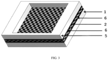
- a conventional stack structure is used, and the membrane and the electrode frame are sealed through sealing gasket 6.
- a 10-cell stack is assembled for an all-vanadium flow battery.
- Leakage testing is performed on the assembled 10-cell 2 kW stack for the all-vanadium flow battery. A longitudinal surface of the membrane 2 is directly exposed, which can easily lead to small longitudinal leakage. For this reason, the maximum internal leakage testing pressure is 0.012 MPa, and the external leakage testing pressure of 0.08 MPa.
- the stack is 130 mm thick, measured by a scale. The battery performance is tested at a constant current of 120 mA/cm 2 , and the battery has a coulomb efficiency of 93.5%.
- Embodiment 1 and Comparative Example 1 use the same assembly process.
- the membrane is welded with the positive electrode frame and the negative electrode frame, improving the sealing reliability of the stack.
- the maximum internal leakage testing pressure is 0.03 MPa, and the external leakage testing pressure is 0.26 MPa.
- the reliability of the stack is improved, the long-term cycling stability of the battery is significantly improved, and the life of the battery is extended.
- the stack in Embodiment 1 is 103 mm thick, and the stack in Comparative Example 1 is 130 mm thick. Compared with Comparative Example 1, in Embodiment 1, the volumetric energy density of the stack is increased by 26.2%.
- the positive electrode frame is made of a non-transparent material including 99wt% PE and 1wt% black masterbatch (PLASBLAK PE2718 by Cabot), and has a transmittance of 1%.
- the negative electrode frame is made of a transparent material including 100wt% PP, and has a transmittance of 95%.
- the membrane is made of a non-transparent material including 99wt% PE and 1wt% black masterbatch (PLASBLAK PE2718 by Cabot), and has a transmittance of 1%.
- the positive electrode frame is 30 cm long, 40 cm wide, and 4.4 mm thick, while the negative electrode frame is 30 cm long, 40 cm wide, and 2.7 mm thick.
- the central through-hole of each of the positive electrode frame and the negative electrode frame is 23.5 cm long and 32.5 cm wide.
- the membrane is 26 cm long and 35 cm wide.
- An encircling step with a width of 5 mm and a thickness of 1 mm is etched at a peripheral edge of the central through-hole of the positive electrode frame.
- the membrane has a thickness of 500 ⁇ m, a porosity of 70%, and a pore size of 1-300 nm.
- the membrane is welded to the encircling step with a width of 5 mm at the peripheral edge of the central through-hole of the negative electrode frame, with a welding power of 1W and a welding speed of 5 mm/s.
- the positive electrode frame and the negative electrode frame are welded together, with a welding power of 14 W and a welding speed of 10 mm/s, to form an integrated electrode frame of the positive electrode frame, the membrane, and the negative electrode frame. In this way, 10 integrated electrode frames are sequentially welded.
- the integrated electrode frames are assembled into a 10-cell 2 kW stack for an all-vanadium flow battery. Leakage testing is performed on the assembled 10-cell stack for the all-vanadium flow battery, with a maximum internal leakage testing pressure of 0.015 MPa and an external leakage testing pressure of 0.08 MPa.
- the stack is 103 mm thick, measured by a scale.
- the battery performance is tested at a constant current of 120 mA/cm 2 , and the battery has a coulomb efficiency of 96.2%.
- Comparative Examples 3 to 4 differing from Embodiment 1 are shown in Table 2, and those the same as Embodiment 1 can be referred to Embodiment 1.
- Table 2 Comp arative Exam ple Material composition of positive electrode frame Material composition of negative electrode frame Transm ittance of positiv e electro de frame % Transm ittance of negativ e electro de frame, % Transm ittance differe nce of positiv e and negativ e electro de frames, % Membra ne and electrode frame welding power and speed Positive and negative electrode frame welding power and speed External and internal leakage testing pressure s of stack Coul omb effici ency of stack % Polyet hylene % P P % W hit e ton er % Polyet hylene % P P % B1 ac k to ne r % Po we r Sp ee d Po we r Sp ee d 3 10 8 9. 7 3.5 10 8 9 0.5 15 5 10 55 5 40 0 10 0. 00 8
Landscapes
- Engineering & Computer Science (AREA)
- Mechanical Engineering (AREA)
- General Chemical & Material Sciences (AREA)
- Sustainable Development (AREA)
- Electrochemistry (AREA)
- Chemical Kinetics & Catalysis (AREA)
- Chemical & Material Sciences (AREA)
- Sustainable Energy (AREA)
- Life Sciences & Earth Sciences (AREA)
- Manufacturing & Machinery (AREA)
- Physics & Mathematics (AREA)
- Optics & Photonics (AREA)
- Toxicology (AREA)
- Electromagnetism (AREA)
- Health & Medical Sciences (AREA)
- Thermal Sciences (AREA)
- Hybrid Cells (AREA)
- Fuel Cell (AREA)
- Sealing Battery Cases Or Jackets (AREA)
- Primary Cells (AREA)
Abstract
Description
- The present application relates to an integrated electrode frame and a preparation method and use thereof.
- Renewable energy sources such as wind and solar energy are inherently random, intermittent, unstable, and difficult to connect directly to the grid, which to some extent limits the development and utilization of renewable energy. The key to solving this problem is to develop energy storage technologies suitable for renewable energy.
- Energy storage technologies include physical and chemical energy storage technologies. Physical energy storage technologies include pumped energy storage technology, compressed air energy storage technology, flywheel energy storage technology, etc. Chemical energy storage technologies are mainly implemented by using lead acid batteries, sodium sulfur batteries, flow batteries, lithium-ion batteries, etc. Each energy storage technology requires a suitable application scenario. flow batteries, sodium sulfur batteries, lead acid batteries, lithium-ion batteries are suitable for large-scale chemical energy storage applications.
- Among flow batteries, the all-vanadium flow battery has independently designed output power and energy storage capacity, and only employs vanadium ions as electrolyte ions, thereby avoiding the phase changes commonly encountered by other batteries during charging and discharging. Overall, the all-vanadium flow battery has attracted much attention due to its long service life, excellent charge and discharge performance, deep discharge without damaging the battery, high safety, and high energy efficiency.
- The stack structure of a traditional all-vanadium flow battery sequentially includes a current collector, a bipolar plate, a sealing gasket, an electrode frame, a sealing gasket, an electrode, a membrane, an electrode, a sealing gasket, an electrode frame, a sealing gasket, a bipolar plate, and a current collector. The membrane is configured to separate the positive electrode from the negative electrode, and the sealing gasket is placed between the membrane and the electrode frame to prevent external leakage of the battery. In addition, such structure requires that the membrane and the electrode frame must be identical in terms of size. In order to meet the assembly and positioning requirements of the stack and the liquidity requirement of the electrolyte, it is necessary to drill holes in the diagonal corners of the membrane. During the long-term operation of the battery, the electrolyte of the stack may leak, resulting in a series of problems, for example, the battery capacity and performance are degraded, and external parts are corroded by the acidic electrolyte, etc. In particular, as the pressure of the battery testing system increases with the increase in the power of the stack, the stack is prone to external and internal leakage due to excessive system pressure, and the electrolyte is prone to leakage due to the rupture of the membrane during drilling. Moreover, in the traditional stack structure, the sealing gasket is required for sealing and isolation between each two parts, resulting in a low volumetric energy density of the battery.
- In order to solve the above technical problems, the present application provides an integrated electrode frame and a preparation method and use thereof. The present application improves the sealing reliability and volumetric energy density of a flow battery by optimizing structures and materials of electrode frames and a membrane.
- In order to achieve the above objective, the present application adopts the following technical solutions:
- A first aspect of the present application provides an integrated electrode frame. The integrated electrode frame includes a positive electrode frame, a negative electrode frame, and a membrane.
- Each of the positive electrode frame and the negative electrode frame is a flat plate with a central through-hole.
- The flat plate has a fluid distribution channel.
- The membrane is placed between the positive electrode frame and the negative electrode frame, and the membrane is located at the through-hole and hermetically connected to a peripheral edge of the through-hole.
- A peripheral edge of the positive electrode frame is hermetically connected to a peripheral edge of the negative electrode frame; and a material composition of a connecting part of the positive electrode frame and the negative electrode frame contains at least one material which is the same as that of the positive electrode frame or the negative electrode frame.
- Optionally, the same material is at least one selected from the group consisting of polypropylene (PP), polyethylene (PE), polystyrene (PS), polycarbonate (PC), acrylonitrile butadiene styrene (ABS), polymethyl methacrylate (PMMA), and polyethylene terephthalate (PET).
- Optionally, the flat plate has a fluid distribution channel.
- Specifically, the fluid distribution channel is provided on a surface of the flat plate, and located on two opposite sides of the surface and close to an edge; another surface of the flat plate is not provided with the fluid distribution channel; the central through-holes of the positive electrode frame and the negative electrode frame are arranged opposite to each other; and the peripheral edges of the through-holes are laminated with each other.
- Optionally, the positive electrode frame and the negative electrode frame have same shape and size.
- The size of the membrane is smaller than the size of the positive electrode frame and the size of the negative electrode frame.
- Specifically, the (outer) peripheral edge of the positive electrode frame and the (outer) peripheral edge of the negative electrode frame have same shape and size.
- In a laminating process, the (outer) peripheral edge of the positive electrode frame and the (outer) peripheral edge of the negative electrode frame are laminated correspondingly; a peripheral edge of the membrane is located in a laminating zone of the positive electrode frame and the negative electrode frame; a gap for sealing between the positive electrode frame and the negative electrode frame is reserved between the peripheral edge of the membrane and the (outer) peripheral edge of each of the positive electrode frame and the negative electrode frame; and a gap for sealing between the membrane and one of the positive electrode frame and the negative electrode frame is reserved between the peripheral edge of the membrane and the central through-hole of the one of the positive electrode frame and the negative electrode frame.
- Specifically, the central through-hole of the positive electrode frame and the central through-hole of the negative electrode frame have same position, shape, and size.
- Optionally, the positive electrode frame or the negative electrode frame has an encircling step around the through-hole; and the membrane is located on the encircling step, and is hermetically connected to the encircling step.
- Optionally, the membrane is non-transparent or transparent.
- One of the positive electrode frame and the negative electrode frame is a transparent electrode frame, and the other of the positive electrode frame and the negative electrode frame is a non-transparent electrode frame.
- Optionally, if the membrane which is hermetically connected to the positive electrode frame is non-transparent, the positive electrode frame is the transparent electrode frame, and the negative electrode frame is the non-transparent electrode frame.
- If the membrane which is hermetically connected to the positive electrode frame is transparent, the positive electrode frame is the non-transparent electrode frame, and the negative electrode frame is the transparent electrode frame.
- A material composition of a connecting part of the membrane and the positive electrode frame contains at least one material which is the same as that of the membrane or the positive electrode frame.
- The same material is at least one selected from the group consisting of PP, PE, PS, PC, ABS, PMMA, and PET.
- Optionally, a laser transmittance of the transparent electrode frame is 20% or above.
- A laser transmittance of the non-transparent electrode frame is 5% or below.
- A difference between the laser transmittance of the transparent electrode frame and the laser transmittance of the non-transparent electrode frame is 15-100%.
- Optionally, the laser transmittance of the transparent electrode frame is 40% or above.
- The laser transmittance of the non-transparent electrode frame is 1% or below.
- The difference between the laser transmittance of the transparent electrode frame and the laser transmittance of the non-transparent electrode frame is 35-100%.
- Specifically, an upper limit of the laser transmittance of the transparent electrode frame is independently selected from 75%, 80%, 90%, 95%, and 100%; and a lower limit of the laser transmittance of the transparent electrode frame is independently selected from 20%, 30%, 40%, 50%, and 60%.
- Specifically, an upper limit of the laser transmittance of the non-transparent electrode frame is independently selected from 2.5%, 3%, 3.5%, 4%, and 5%; a lower limit of the laser transmittance of the non-transparent electrode frame is independently selected from 0, 0.5%, 1%, 1.5%, and 2%.
- Optionally, the transparent material includes at least one selected from the group consisting of PP, PE, PS, PC, ABS, PMMA, and PET.
- The non-transparent material includes the transparent material and a toner.
- Optionally, the toner is at least one selected from the group consisting of a black toner, a yellow toner, a tan toner, a brown toner, and a dark blue toner.
- The transparent material further includes a white toner.
- Optionally, the membrane has a thickness of 100 µm to 3 mm, a porosity of 40-90%, and a pore size of 1-300 nm.
- Optionally, a content of the same material accounts for 10% or more of a total weight of the material composition of respective structure.
- Optionally, a content of the same material accounts for 40% or more of a total weight of the material composition of respective structure.
- Specifically, an upper limit of the thickness of the membrane is independently selected from 1,200 µm, 1,500 µm, 2,000 µm, 2,500 µm, and 3,000 µm; and a lower limit of the thickness of the membrane is independently selected from 100 µm, 300 µm, 500 µm, 700 µm, and 1,000 µm.
- Specifically, an upper limit of the porosity of the membrane is independently selected from 65%, 70%, 75%, 80%, and 90%; and a lower limit of the porosity of the membrane is independently selected from 40%, 45%, 50%, 55%, and 60%.
- A second aspect of the present application provides a method for preparing the integrated electrode frame.
- The method includes at least the following steps:
- covering the membrane on a surface of one of the positive electrode frame and the negative electrode frame where the through-hole is formed, and hermetically connecting the membrane with the peripheral edge of the through-hole to form a membrane-bonded electrode frame; and
- laminating the other of the positive electrode frame and the negative electrode frame with the membrane-bonded electrode frame, and hermetically connecting the peripheral edge of the other of the positive electrode frame and the negative electrode frame with the peripheral edge of the membrane-bonded electrode frame, where the membrane is located between the positive electrode frame and the negative electrode frame to form the integrated electrode frame.
- Optionally, when the membrane is transparent, the method includes:
- covering the membrane on a surface of a non-transparent electrode frame where the through-hole is formed, and hermetically connecting the membrane with the peripheral edge of the through-hole to form a membrane-bonded non-transparent electrode frame; and
- laminating a transparent electrode frame with the membrane-bonded non-transparent electrode frame, and fixedly connecting a peripheral edge of the transparent electrode frame with a peripheral edge of the membrane-bonded non-transparent electrode frame, where the membrane is located between the transparent electrode frame and the non-transparent electrode frame to form the integrated electrode frame; and
- alternatively, when the membrane is non-transparent, the method includes:
- covering the membrane on a surface of the transparent electrode frame where the through-hole is formed, and hermetically connecting the membrane with the peripheral edge of the through-hole to form a membrane-bonded transparent electrode frame; and
- laminating the non-transparent electrode frame with the membrane-bonded transparent electrode frame, and fixedly connecting a peripheral edge of the non-transparent electrode frame with a peripheral edge of the membrane-bonded transparent electrode frame, where the membrane is located between the non-transparent electrode frame and the transparent electrode frame to form the integrated electrode frame.
- Optionally, hermetical connection is implemented by laser welding.
- Specifically, the method includes the following process:
- A: when the membrane is transparent:
- placing the peripheral edge of the membrane on the non-transparent electrode frame; covering an open end of the central through-hole with the membrane; bonding the peripheral edge of the membrane on a side surface to the non-transparent electrode frame around the central through-hole, that is, hermetically and fixedly connecting the peripheral edge of the membrane with the non-transparent electrode frame around the central through-hole by welding; alternatively, etching the encircling step at the peripheral edge on the open end of the central through-hole on a side surface of the non-transparent electrode frame close to the membrane, in a direction away from the central through-hole; and bonding the peripheral edge on the side surface of the membrane to the encircling step, that is, hermetically and fixedly connecting the peripheral edge of the membrane with the encircling step or the encircling step and the non-transparent electrode frame around the encircling step by welding; and
- laminating the transparent electrode frame with the membrane-bonded non-transparent electrode frame; hermetically and fixedly connecting the peripheral edge of the positive electrode frame and the peripheral edge of the negative electrode frame by welding, such that the positive electrode frame, the membrane, and the negative electrode frame are sequentially laminated into the integrated electrode frame by welding; and
- alternatively, B: when the membrane is non-transparent:
- placing the peripheral edge of the membrane on the transparent electrode frame; covering an open end of the central through-hole with the membrane; bonding the peripheral edge of the membrane on a side surface to the transparent electrode frame around the central through-hole, that is, hermetically and fixedly connecting the peripheral edge of the membrane with the transparent electrode frame around the central through-hole by welding; alternatively, etching the encircling step at the peripheral edge on the open end of the central through-hole on a side surface of the transparent electrode frame close to the membrane, in a direction away from the central through-hole; and bonding the peripheral edge on the side surface of the membrane to the encircling step, that is, hermetically and fixedly connecting the peripheral edge of the membrane with the encircling step or the encircling step and the transparent electrode frame around the encircling step by welding; and
- laminating the transparent electrode frame with the membrane-bonded non-transparent electrode frame; hermetically fixedly connecting the peripheral edge of the positive electrode frame and the peripheral edge of the negative electrode frame by welding, such that the positive electrode frame, the membrane, and the negative electrode frame are sequentially laminated into the integrated electrode frame by welding.
- During the laminating process, the side surface of one of the positive electrode frame and the negative electrode frame with the fluid distribution channel is laminated with the surface of the other of the positive electrode frame and the negative electrode frame without the fluid distribution channel. The central through-hole of the positive electrode frame and the central through-hole of the negative electrode frame are arranged opposite to each other. The peripheral edges of the through-holes are laminated with each other, and the laminating parts are welded to form an encircling welding zone.
- Optionally, the membrane is hermetically connected to the peripheral edge of the through-hole by laser welding with a welding power of 2-50 W and a welding speed of 2-20 mm/s.
- Specifically, an upper limit of the welding power is independently selected from 22 W, 25 W, 33 W, 35 W, 40 W, 45 W, and 50 W; and a lower limit of the welding power is independently selected from 2 W, 5 W, 10 W, 13 W, 15 W, 17 W, and 20 W.
- Specifically, an upper limit of the welding speed is independently selected from 10 mm/s, 11 mm/s, 13 mm/s, 15 mm/s, 17 mm/s, 19 mm/s, and 20 mm/s; and a lower limit of the welding speed is independently selected from 2 mm/s, 3 mm/s, 4 mm/s, 5 mm/s, 6 mm/s, 7 mm/s, and 8 mm/s.
- Optionally, the peripheral edges of the electrode frames are hermetically connected by laser welding with a welding power of 15-300 W and a welding speed of 5-50 mm/s.
- Specifically, an upper limit of the welding power is independently selected from 130W, 140W, 150W, 170W, 200W, 260W, and 300W; and a lower limit of the welding power is independently selected from 15W, 30W, 60W, 70W, 75W, 80W, and 100W.
- Specifically, an upper limit of the welding speed is independently selected from 20 mm/s, 25 mm/s, 30 mm/s, 35 mm/s, 40 mm/s, 45 mm/s, and 50 mm/s; and a lower limit of the welding speed is independently selected from 5 mm/s, 8 mm/s, 10 mm/s, 13 mm/s, 15 mm/s, 17 mm/s, and 18 mm/s.
- A third aspect of the present application provides a use of the integrated electrode frame described in any one of the above paragraphs or an integrated electrode frame prepared by the method described in any one of the above paragraphs for a stack of all-vanadium flow batteries, where the stack includes one cell or a plurality of cells connected in series; the cell includes the integrated electrode frame; and the stack has a power of 0.5-100 kW.
- The present application has the following beneficial effects:
- 1) In the present application, the structures and materials of the electrode frames and the membrane are optimized to achieve a direct hermetical connection between the membrane and the electrode frames and improve the sealing reliability of the all-vanadium flow battery. The present application is particularly applicable to a high-power flow battery for large-scale energy storage.
- 2) The present application achieves the sealing of the battery structure through direct welding, reducing the use of the sealing gasket, reducing the thickness of the battery, and improving the volumetric energy density of the battery.
- 3) The present application uses the membrane with high durability, high ion selectivity, and high ion conductivity, which improves the performance and cycling stability of the battery.
- 4) The present application reduces the use area of the membrane and improves the utilization of the membrane.
- 5) The present application broadens the scope of use of the membrane for the all-vanadium flow battery and the sealing between the membrane and the electrode frame.
-
-
FIG. 1 is a structural diagram of a membrane and a positive electrode frame that are welded together according toEmbodiment 1 of the present application; -
FIG. 2 is a structural diagram of an integrated electrode frame according toEmbodiment 1 of the present application; and -
FIG. 3 is a structural diagram of a conventional stack of all-vanadium flow batteries. - 1. positive electrode frame; 2. membrane; 3. through-hole; 4. encircling step; 5. negative electrode frame; and 6. sealing gasket.
- The present disclosure will be described in detail below with reference to embodiments, but the present disclosure is not limited to these embodiments.
- A positive electrode frame is made of 100wt% polyethylene (PE), and has a transmittance of 95%. A negative electrode frame is made of a non-transparent material including 99wt% PE and 1wt% black masterbatch (PLASBLAK PE2718 by Cabot), and has a transmittance of 1%. A membrane is made of a non-transparent material including 99wt% PE and 1wt% black masterbatch (PLASBLAK PE2718 by Cabot), and has a transmittance of 1%. The
positive electrode frame 1 is 30 cm long, 40 cm wide, and 4.4 mm thick, while thenegative electrode frame 5 is 30 cm long, 40 cm wide, and 2.7 mm thick. Central through-hole 3 of each of the positive electrode frame and the negative electrode frame is 23.5 cm long and 32.5 cm wide. Themembrane 2 is 26 cm long and 35 cm wide. Encirclingstep 4 with a width of 5 mm and a thickness of 1 mm is etched at a peripheral edge of the central through-hole 3 of thepositive electrode frame 1 in a direction away from the through-hole. The membrane has a thickness of 500 µm, a porosity of 70%, and a pore size of 1-300 nm. - As shown in
FIGS. 1 and 2 , themembrane 2 is welded to theencircling step 4 of thepositive electrode frame 1 by laser welding, with a welding power of 10 W and a welding speed of 8 mm/s. Thepositive electrode frame 1 and thenegative electrode frame 5 are welded together, with a welding power of 60 W and a welding speed of 18 mm/s, to form an integrated electrode frame of thepositive electrode frame 1, themembrane 2, and thenegative electrode frame 5. In this way, 10 integrated electrode frames are sequentially welded, and are assembled into a 10-cell 2 kW stack for an all-vanadium flow battery. - Leakage testing is performed on the assembled 10-cell stack for the all-vanadium flow battery, with a maximum internal leakage testing pressure of 0.03 MPa and an external leakage testing pressure of 0.26 MPa. No air leakage is observed, and the stack is 103 mm thick, measured by a scale. The battery performance is tested at a constant current of 120 mA/cm2, and the battery has a coulomb efficiency of 99.3%.
- In these embodiments, the test conditions and process of the stack are the same (with the same parameter units) as those in
Embodiment 1, except for the following aspects. - The material composition of the positive electrode frame and the negative electrode frame is shown in Table 1. PLASWITER PE7606 by Cabot is selected as a white toner. The membrane is made of a non-transparent material including 80wt% PE, 19wt% of PP, and 1wt% black masterbatch (PLASBLAK PE2718 by Cabot), and has a transmittance of 1%. The positive electrode frame is 30 cm long, 40 cm wide, and 4.4 mm thick, while the negative electrode frame is 30 cm long, 40 cm wide, and 2.7 mm thick. The central through-hole of each of the positive electrode frame and the negative electrode frame is 23.5 cm long and 32.5 cm wide. The membrane is 26 cm long and 35 cm wide. The encircling step with a width of 5 mm and a thickness of 1 mm is etched at a peripheral edge of the central through-hole of the positive electrode frame in a direction away from the through-hole. The assembled stack is 103 mm thick. In
Embodiments 2 to 12, an integrated electrode frame of the membrane, the positive electrode frame, and the negative electrode frame is formed. Multiple integrated electrode frames are assembled into a 10-cell 2 kW stack for an all-vanadium flow battery.Table 1 Em bod ime nts Material composition of positive electrode frame (by weight) Material composition of negative electrode frame (by weight) Tran smit tanc e of posit ive elect rode fram e, % Tr an s mi tta nc e of ne ga tiv e elec tro de fra m e, % Tran smit tanc e diffe renc e of posit ive and nega tive electrode fram es, % Membran e and electrode frame welding power and speed Positive and negative electrode frame welding power and speed External and internal leakage testing pressures of stack Coul omb effici ency of stack % Poly ethy lene % PP % Whi te mast erba tch, % PE, % PP, % Blac k mast erba tch, % Pow er Sp ee d Pow er Spee d 2 10 89.7 0.3 10 89 1 90 1 89 15 8 70 18 0.029 0.25 98.9 3 10 89.7 0.3 20 79 1 90 1 89 13 8 70 18 0.027 0.25 98.8 4 20 79.2 0.8 10 89 1 75 1 74 20 8 80 17 0.025 0.24 98.9 5 20 79.2 0.8 30 69 1 75 1 74 15 8 70 17 0.025 0.23 99.0 6 30 68.8 1.2 10 89 1 60 1 59 25 7 140 15 0.023 0.22 99.5 7 30 68.8 1.2 40 59 0.8 60 3 57 22 6 130 13 0.023 0.22 99.3 8 40 58.3 1.7 20 79.2 0.8 40 3 37 30 6 170 10 0.020 0.20 99.1 9 40 58.3 1.7 50 49.5 0.5 40 5 35 25 5 150 10 0.020 0.20 99.5 10 50 47 3 10 89.5 0.5 20 5 15 35 5 300 10 0.018 0.17 99.1 11 50 47 3 50 49.5 0.5 20 5 15 33 5 260 10 0.018 0.17 98.9 12 15 84.5 0.5 15 84 1 80 1 79 17 8 75 17 0.026 0.24 98.2 13 100 - - 10 89 1 95 1 94 10 8 60 18 0.030 0.26 98.7 - The positive electrode frame is made of 100wt% PE, and has a transmittance of 95%. The negative electrode frame is made of a non-transparent material including 99wt% PE and 1wt% black masterbatch (PLASBLAK PE2718 by Cabot), and has a transmittance of 1%. The membrane is made of a non-transparent material including 99wt% PE and 1wt% black masterbatch (PLASBLAK PE2718 by Cabot), and has a transmittance of 1%. The
positive electrode frame 1 is 30 cm long, 40 cm wide, and 4.4 mm thick, while thenegative electrode frame 5 is 30 cm long, 40 cm wide, and 2.7 mm thick. The central through-hole 3 of each of the positive electrode frame and the negative electrode frame is 23.5 cm long and 32.5 cm wide. Themembrane 2 is 26 cm long and 35 cm wide. The membrane has a thickness of 500 µm, a porosity of 70%, and a pore size of 1-300 nm. - The
membrane 2 is welded to the peripheral edge of the central through-hole of thepositive electrode frame 1, with a welding power of 30W and a welding speed of 5 mm/s. Thepositive electrode frame 1 and thenegative electrode frame 5 are welded together, with a welding power of 60 W and a welding speed of 18 mm/s, to form an integrated electrode frame of thepositive electrode frame 1, themembrane 2, and thenegative electrode frame 5. In this way, 10 integrated electrode frames are sequentially welded, and are assembled into a 10-cell 2 kW stack for an all-vanadium flow battery. - Leakage testing is performed on the assembled 10-cell stack for the all-vanadium flow battery, with a maximum internal leakage testing pressure of 0.025 MPa and an external leakage testing pressure of 0.26 MPa. No air leakage is observed, and the stack is 108 mm thick, measured by a scale. The battery performance is tested at a constant current of 120 mA/cm2, and the battery has a coulomb efficiency of 99.0%.
- The test results of the above embodiments show that:
- 1. When the content of the same material in the welded material reaches 10% or more of the welded material, both the internal and external leakage testing of the assembled stack meet the requirements (the internal leakage testing pressure is at least 0.018 MPa, and the external leakage testing pressure is at least 0.17 MPa).
- 2. When the content of the same material in the welded material increases, the ability of the stack to resist both internal and external leakage testing pressures is improved.
- 3. When the transmittance of the positive electrode frame is not lower than 20% and the transmittance of the negative electrode frame is not higher than 5%, effective welding can be achieved, thereby ensuring the air tightness of the stack.
- 4. As the transmittance difference between the positive electrode frame and the negative electrode frame continues to increase, the ability of the finally assembled stack to resist internal and external leakage testing pressures continues to improve, and the laser welding power continues to decrease, saving energy. In addition, under the condition that the transmittance difference between the positive electrode frame and the negative electrode frame remains unchanged, the laser welding power is increased, thereby increasing the welding speed.
- All other conditions not mentioned in the following Comparative Examples 1 to 4 are the same as those in
Embodiment 1. - The positive electrode frame is made of 100wt% PE, and has a transmittance of 95%. The negative electrode frame is made of a non-transparent material including 99wt% PE and 1wt% black masterbatch (PLASBLAK PE2718 by Cabot), and has a transmittance of 1%. The membrane is made of a non-transparent material including 99wt% PE and 1wt% black masterbatch (PLASBLAK PE2718 by Cabot), and has a transmittance of 1%. Each of the positive electrode frame and the negative electrode frame is 30 cm long, 40 cm wide, and 3.55 mm thick. The central through-hole of each of the positive electrode frame and the negative electrode frame is 23.5 cm long and 32.5 cm wide. The membrane is 30 cm long and 40 cm wide. The membrane has a thickness of 500 µm, a porosity of 70%, and a pore size of 1-300 nm.
- As shown in
FIG. 3 , a conventional stack structure is used, and the membrane and the electrode frame are sealed through sealinggasket 6. With the same assembly process, a 10-cell stack is assembled for an all-vanadium flow battery. - Leakage testing is performed on the assembled 10-
cell 2 kW stack for the all-vanadium flow battery. A longitudinal surface of themembrane 2 is directly exposed, which can easily lead to small longitudinal leakage. For this reason, the maximum internal leakage testing pressure is 0.012 MPa, and the external leakage testing pressure of 0.08 MPa. The stack is 130 mm thick, measured by a scale. The battery performance is tested at a constant current of 120 mA/cm2, and the battery has a coulomb efficiency of 93.5%. -
Embodiment 1 and Comparative Example 1 use the same assembly process. The membrane is welded with the positive electrode frame and the negative electrode frame, improving the sealing reliability of the stack. The maximum internal leakage testing pressure is 0.03 MPa, and the external leakage testing pressure is 0.26 MPa. The reliability of the stack is improved, the long-term cycling stability of the battery is significantly improved, and the life of the battery is extended. The stack inEmbodiment 1 is 103 mm thick, and the stack in Comparative Example 1 is 130 mm thick. Compared with Comparative Example 1, inEmbodiment 1, the volumetric energy density of the stack is increased by 26.2%. - The positive electrode frame is made of a non-transparent material including 99wt% PE and 1wt% black masterbatch (PLASBLAK PE2718 by Cabot), and has a transmittance of 1%. The negative electrode frame is made of a transparent material including 100wt% PP, and has a transmittance of 95%. The membrane is made of a non-transparent material including 99wt% PE and 1wt% black masterbatch (PLASBLAK PE2718 by Cabot), and has a transmittance of 1%. The positive electrode frame is 30 cm long, 40 cm wide, and 4.4 mm thick, while the negative electrode frame is 30 cm long, 40 cm wide, and 2.7 mm thick. The central through-hole of each of the positive electrode frame and the negative electrode frame is 23.5 cm long and 32.5 cm wide. The membrane is 26 cm long and 35 cm wide. An encircling step with a width of 5 mm and a thickness of 1 mm is etched at a peripheral edge of the central through-hole of the positive electrode frame. The membrane has a thickness of 500 µm, a porosity of 70%, and a pore size of 1-300 nm.
- The membrane is welded to the encircling step with a width of 5 mm at the peripheral edge of the central through-hole of the negative electrode frame, with a welding power of 1W and a welding speed of 5 mm/s. The positive electrode frame and the negative electrode frame are welded together, with a welding power of 14 W and a welding speed of 10 mm/s, to form an integrated electrode frame of the positive electrode frame, the membrane, and the negative electrode frame. In this way, 10 integrated electrode frames are sequentially welded.
- The integrated electrode frames are assembled into a 10-
cell 2 kW stack for an all-vanadium flow battery. Leakage testing is performed on the assembled 10-cell stack for the all-vanadium flow battery, with a maximum internal leakage testing pressure of 0.015 MPa and an external leakage testing pressure of 0.08 MPa. The stack is 103 mm thick, measured by a scale. The battery performance is tested at a constant current of 120 mA/cm2, and the battery has a coulomb efficiency of 96.2%. - The comparison of the data of
Embodiment 1 and Comparative Example 2 shows that although the two materials without the same material can be welded together, their sealing reliability is poor, and they cannot meet the pressure performance requirements of a high-power stack. - The testing conditions of Comparative Examples 3 to 4 differing from
Embodiment 1 are shown in Table 2, and those the same asEmbodiment 1 can be referred toEmbodiment 1.Table 2 Comp arative Exam ple Material composition of positive electrode frame Material composition of negative electrode frame Transm ittance of positiv e electro de frame % Transm ittance of negativ e electro de frame, % Transm ittance differe nce of positiv e and negativ e electro de frames, % Membra ne and electrode frame welding power and speed Positive and negative electrode frame welding power and speed External and internal leakage testing pressure s of stack Coul omb effici ency of stack % Polyet hylene % P P % W hit e ton er % Polyet hylene % P P % B1 ac k to ne r % Po we r Sp ee d Po we r Sp ee d 3 10 8 9. 7 3.5 10 8 9 0.5 15 5 10 55 5 40 0 10 0. 00 8 0. 05 6 91 4 100 - - 5 9 4 1 95 1 94 10 8 60 18 0. 01 0. 06 92 - The comparison of the comparative examples with the embodiment shows that:
- 1. The same assembly process is used, and the membrane is welded with the positive electrode frame and the negative electrode frame. The design improves the ability of the stack to resist the leakage testing pressures, improves the coulomb efficiency of the battery, and improves the operational reliability of the stack.
- 2. When the same material accounts for more than 10wt% of the welded material, the welding reliability is guaranteed, and the withstand pressure increases with the increase of the content.
- 3. The membrane is welded with the positive electrode frame and the negative electrode frame, and the positive electrode frame and the negative electrode frame are directly welded to form the integrated electrode frame. There is no need to drill a flow channel hole on the membrane, improving the reliability of the membrane and extending the service life of the battery.
- 4. The present application reduces the use of the sealing gasket, reduces the thickness of the battery, reduces the volume of the stack, and improves the volumetric energy density of the battery.
- 5. Compared with traditional structures, the present application reduces the use of the sealing material, and reduces the area of the membrane by about 30%, greatly reducing the material cost of the stack.
- The above embodiments are merely some of the embodiments of the present application, and do not limit the present application in any form. Although the present application is disclosed above with the preferred embodiments, the present application is not limited thereto. Some changes or modifications made by any technical personnel familiar with the profession using the technical content disclosed above without departing from the scope of the technical solutions of the present application are equivalent to equivalent implementation cases and fall within the scope of the technical solutions.
Claims (20)
- An integrated electrode frame, comprising a positive electrode frame, a negative electrode frame, and a membrane, whereineach of the positive electrode frame and the negative electrode frame is a flat plate with a central through-hole;the membrane is placed between the positive electrode frame and the negative electrode frame, and the membrane is located at the through-hole and hermetically connected to a peripheral edge of the through-hole; anda peripheral edge of the positive electrode frame is hermetically connected to a peripheral edge of the negative electrode frame; and a material composition of a connecting part of the positive electrode frame and the negative electrode frame contains at least one material which is the same as that of the positive electrode frame or the negative electrode frame.
- The integrated electrode frame according to claim 1, wherein the same material is at least one selected from the group consisting of polypropylene (PP), polyethylene (PE), polystyrene (PS), polycarbonate (PC), acrylonitrile butadiene styrene (ABS), polymethyl methacrylate (PMMA), and polyethylene terephthalate (PET).
- The integrated electrode frame according to claim 1, wherein the positive electrode frame and the negative electrode frame have same shape and size; and
a size of the membrane is smaller than a size of the positive electrode frame and a size of the negative electrode frame. - The integrated electrode frame according to claim 3, wherein the positive electrode frame or the negative electrode frame has an encircling step around the through-hole; and the membrane is located on the encircling step, and is hermetically connected to the encircling step.
- The integrated electrode frame according to claim 1, wherein the membrane is non-transparent or transparent; and
one of the positive electrode frame and the negative electrode frame is transparent, and the other of the positive electrode frame and the negative electrode frame is non-transparent. - The integrated electrode frame according to claim 5, whereinif the membrane which is hermetically connected to the positive electrode frame is non-transparent, the positive electrode frame is transparent, and the negative electrode frame is non-transparent;if the membrane which is hermetically connected to the positive electrode frame is transparent, the positive electrode frame is non-transparent, and the negative electrode frame is transparent;a material composition of a connecting part of the membrane and the positive electrode frame contains at least one material which is the same as that of the membrane or the positive electrode frame; andthe same material is at least one selected from the group consisting of PP, PE, PS, PC, ABS, PMMA, and PET.
- The integrated electrode frame according to claim 5, whereina laser transmittance of the transparent electrode frame is 20% or above;a laser transmittance of the non-transparent electrode frame is 5% or below; anda difference of the laser transmittance between the transparent electrode frame and the non-transparent electrode frame is 15-100%.
- The integrated electrode frame according to claim 7, whereinthe laser transmittance of the transparent electrode frame is 40% or above;the laser transmittance of the non-transparent electrode frame is 1% or below; andthe difference of the laser transmittance between the transparent electrode frame and the non-transparent electrode frame is 35-100%.
- The integrated electrode frame according to claim 5, wherein the transparent material comprises at least one selected from the group consisting of PP, PE, PS, PC, ABS, PMMA, and PET; and
the non-transparent material comprises the transparent material and a toner. - The integrated electrode frame according to claim 9, whereinthe toner is at least one selected from the group consisting of a black toner, a yellow toner, a tan toner, a brown toner, and a dark blue toner; andthe transparent material further comprises a white toner.
- The integrated electrode frame according to claim 1, wherein the membrane has a thickness of 100 µm to 3 mm, a porosity of 40-90%, and a pore size of 1-300 nm.
- The integrated electrode frame according to claim 1, wherein a content of the same material accounts for 10% or more of a total weight of the material composition of respective structure.
- The integrated electrode frame according to claim 1, wherein a content of the same material accounts for 40% or more of a total weight of the material composition of respective structure.
- The integrated electrode frame according to claim 1, wherein the flat plate has a fluid distribution channel.
- A method for preparing the integrated electrode frame according to any one of claims 1 to 14, comprising at least the following steps:covering the membrane on a surface of one of the positive electrode frame and the negative electrode frame where the through-hole is formed, and hermetically connecting the membrane with the peripheral edge of the through-hole to form a membrane-bonded electrode frame; andlaminating the other of the positive electrode frame and the negative electrode frame with the membrane-bonded electrode frame, and hermetically connecting a peripheral edge of the other of the positive electrode frame and the negative electrode frame with a peripheral edge of the membrane-bonded electrode frame, wherein the membrane is located between the positive electrode frame and the negative electrode frame to form the integrated electrode frame.
- The method according to claim 15, wherein when the membrane is transparent, the method comprises:covering the membrane on the surface of a non-transparent electrode frame where the through-hole is formed, and hermetically connecting the membrane with the peripheral edge of the through-hole to form a membrane-bonded non-transparent electrode frame; andlaminating a transparent electrode frame with the membrane-bonded non-transparent electrode frame, and fixedly connecting a peripheral edge of the transparent electrode frame with a peripheral edge of the membrane-bonded non-transparent electrode frame, wherein the membrane is located between the transparent electrode frame and the non-transparent electrode frame to form the integrated electrode frame; andalternatively, when the membrane is non-transparent, the method comprises:covering the membrane on the surface of the transparent electrode frame where the through-hole is formed, and hermetically connecting the membrane with the peripheral edge of the through-hole to form a membrane-bonded transparent electrode frame; andlaminating the non-transparent electrode frame with the membrane-bonded transparent electrode frame, and fixedly connecting a peripheral edge of the non-transparent electrode frame with a peripheral edge of the membrane-bonded transparent electrode frame, wherein the membrane is located between the non-transparent electrode frame and the transparent electrode frame to form the integrated electrode frame.
- The method according to claim 15, wherein hermetical connection is implemented by laser welding.
- The method according to claim 17, wherein the membrane is hermetically connected to the peripheral edge of the through-hole by laser welding with a welding power of 2-50 W and a welding speed of 2-20 mm/s.
- The method according to claim 17, wherein the peripheral edges of the electrode frames are hermetically connected by laser welding with a welding power of 15-300 W and a welding speed of 5-50 mm/s.
- A use of the integrated electrode frame according to any one of claims 1 to 14 or an integrated electrode frame prepared by the method according to any one of claims 15 to 19 for a stack of all-vanadium flow batteries, wherein the stack comprises one cell or a plurality of cells connected in series; and the cell comprises the integrated electrode frame.
Applications Claiming Priority (2)
| Application Number | Priority Date | Filing Date | Title |
|---|---|---|---|
| CN202010570390.1A CN113823806B (en) | 2020-06-19 | 2020-06-19 | Integrated electrode frame structure for all-vanadium redox flow battery, preparation method and application |
| PCT/CN2020/101331 WO2021253543A1 (en) | 2020-06-19 | 2020-07-10 | Integrated electrode frame structure, and preparation method therefor and application thereof |
Publications (2)
| Publication Number | Publication Date |
|---|---|
| EP4184626A1 true EP4184626A1 (en) | 2023-05-24 |
| EP4184626A4 EP4184626A4 (en) | 2025-07-30 |
Family
ID=78912179
Family Applications (1)
| Application Number | Title | Priority Date | Filing Date |
|---|---|---|---|
| EP20941203.0A Pending EP4184626A4 (en) | 2020-06-19 | 2020-07-10 | INTEGRATED ELECTRODE FRAME STRUCTURE AND MANUFACTURING METHOD THEREFOR AND APPLICATION THEREOF |
Country Status (5)
| Country | Link |
|---|---|
| US (1) | US20230402622A1 (en) |
| EP (1) | EP4184626A4 (en) |
| CN (1) | CN113823806B (en) |
| CA (1) | CA3196914A1 (en) |
| WO (1) | WO2021253543A1 (en) |
Family Cites Families (32)
| Publication number | Priority date | Publication date | Assignee | Title |
|---|---|---|---|---|
| JPS5928582A (en) * | 1982-08-06 | 1984-02-15 | Permelec Electrode Ltd | Electrolytic electrode |
| US5068160A (en) * | 1990-04-17 | 1991-11-26 | Ensci, Inc. | Bipolar plate battery |
| FR2686808B1 (en) * | 1992-02-05 | 1994-05-06 | Trailigaz Cie Gle Ozone | DIFFUSION BODY OF A GASEOUS MIXTURE CONTAINING OZONE. |
| JP3682244B2 (en) * | 2001-06-12 | 2005-08-10 | 住友電気工業株式会社 | Cell frame for redox flow battery and redox flow battery |
| DE10261482A1 (en) * | 2002-12-23 | 2004-07-01 | Basf Ag | Fuel cell module for polymer electrolyte membrane fuel cell stacks used e.g. in vehicles comprises a bipolar plate and a membrane-electrode unit |
| JP2006012794A (en) * | 2004-05-26 | 2006-01-12 | Kansai Paint Co Ltd | Photocell and manufacturing method therefor |
| KR101052353B1 (en) * | 2009-11-04 | 2011-07-27 | 한국과학기술원 | Thermal management fuel cell visualization device |
| DE102010023252A1 (en) * | 2010-06-09 | 2011-12-15 | Daimler Ag | Method for manufacturing fuel cell stack of fuel cells, involves securing frame element in bottom portion of front end of bipolar plate in fluid tight manner, and securing membrane electrode unit at top face of another frame element |
| CN102290593B (en) * | 2011-08-01 | 2014-04-09 | 中国东方电气集团有限公司 | Flow cell stack and flow cell system with same |
| CN202308168U (en) * | 2011-09-30 | 2012-07-04 | 珠海锂源新能源科技有限公司 | Efficient electrode frame and integrated structure of electrode frame and diaphragm |
| CN103840188B (en) * | 2012-11-23 | 2016-01-20 | 中国科学院大连化学物理研究所 | A kind of electric pile structure of flow battery |
| JP2015228364A (en) * | 2014-05-02 | 2015-12-17 | 昭和電工株式会社 | Redox flow battery |
| TWI521768B (en) * | 2014-06-30 | 2016-02-11 | 元智大學 | Flow battery stack with sensor strip inside |
| CN204516844U (en) * | 2015-02-05 | 2015-07-29 | 四川中物电新能源科技有限公司 | Flow battery bipolar plates and flow cell pile |
| CN107431251B (en) * | 2015-03-19 | 2020-02-18 | 日本碍子株式会社 | Battery and method of assembling the same |
| KR101560202B1 (en) * | 2015-04-30 | 2015-10-14 | 스탠다드에너지(주) | Redox flow battery |
| US20170229715A1 (en) * | 2016-02-04 | 2017-08-10 | Institute of Nuclear Energy Research, Atomic Energy Council, Executive Yuan, R.O.C. | Method of Fabricating Bipolar Pate of Flow Cell |
| CN107871880A (en) * | 2016-09-22 | 2018-04-03 | 中国科学院大连化学物理研究所 | A kind of integrated zinc-bromine flow battery and its assemble method |
| WO2018086482A1 (en) * | 2016-11-09 | 2018-05-17 | 大连融科储能技术发展有限公司 | Electrode structure of flow battery, flow battery stack, and sealing structure for flow battery stack |
| WO2018231964A1 (en) * | 2017-06-13 | 2018-12-20 | Kato Garrett Scott | Floating frame plate assembly |
| JP6848799B2 (en) * | 2017-10-05 | 2021-03-24 | トヨタ自動車株式会社 | How to manufacture a single cell of a fuel cell |
| DE202018101843U1 (en) * | 2018-04-05 | 2019-07-12 | Zae Bayern Bay. Zentrum Für Angewandte Energieforschung E.V. | Flow frame for chemical reactors, especially for redox flow batteries, and redox flow battery with such a flow frame |
| CN108550885B (en) * | 2018-06-26 | 2024-03-15 | 杭州德海艾科能源科技有限公司 | Electrode frame for all-vanadium redox flow battery |
| CN208589496U (en) * | 2018-08-09 | 2019-03-08 | 上海电气集团股份有限公司 | A kind of liquid flow frame and its flow battery |
| FR3085548B1 (en) * | 2018-09-03 | 2020-11-27 | Kemiwatt | STACKING OF ELECTROCHEMICAL REDOX CELLS IN FLUX WITH REDUCED SHUNT |
| CN109216743A (en) * | 2018-09-21 | 2019-01-15 | 马东亮 | Integrated oxidization restores flow cell pile |
| CN111106397B (en) * | 2018-10-25 | 2021-04-30 | 中国科学院大连化学物理研究所 | Zinc-nickel accumulator |
| CN109494377B (en) * | 2018-11-13 | 2021-11-16 | 中南大学 | Integrated bipolar electrode and preparation method and application thereof |
| CN109361004B (en) * | 2018-11-29 | 2023-08-11 | 南京邮电大学 | A housing structure for a liquid flow single battery system |
| CN111261891A (en) * | 2018-11-30 | 2020-06-09 | 中国科学院大连化学物理研究所 | Weldable bipolar plate for flow battery and its preparation and application |
| CN111261895B (en) * | 2018-11-30 | 2021-04-27 | 中国科学院大连化学物理研究所 | Flow battery electrode frame and application thereof and flow battery |
| CN109786778A (en) * | 2019-01-28 | 2019-05-21 | 威海南海碳材料科技研究院有限公司 | A kind of composite dual-electrode plates used for all-vanadium redox flow battery and preparation method thereof |
-
2020
- 2020-06-19 CN CN202010570390.1A patent/CN113823806B/en active Active
- 2020-07-10 CA CA3196914A patent/CA3196914A1/en active Pending
- 2020-07-10 US US18/036,393 patent/US20230402622A1/en active Pending
- 2020-07-10 WO PCT/CN2020/101331 patent/WO2021253543A1/en not_active Ceased
- 2020-07-10 EP EP20941203.0A patent/EP4184626A4/en active Pending
Also Published As
| Publication number | Publication date |
|---|---|
| EP4184626A4 (en) | 2025-07-30 |
| CN113823806A (en) | 2021-12-21 |
| US20230402622A1 (en) | 2023-12-14 |
| WO2021253543A1 (en) | 2021-12-23 |
| CA3196914A1 (en) | 2021-12-23 |
| CN113823806B (en) | 2023-02-03 |
Similar Documents
| Publication | Publication Date | Title |
|---|---|---|
| CN102122722B (en) | Solid oxide fuel cell stack | |
| CN108172857B (en) | A fuel cell stack flow field plate supporting high current density discharge | |
| CN101587959B (en) | An electrode frame and an all-vanadium liquid flow energy storage battery stack | |
| CN114520345B (en) | Integrated electrode frame with bipolar plate and preparation and application thereof | |
| CN106876765B (en) | A flow battery stack | |
| CN108598543A (en) | A kind of flow battery | |
| CN210778817U (en) | Electrode frame and bipolar plate's integral type structure | |
| CN100355135C (en) | Fuel cell and decomposing method thereof | |
| CN115472884A (en) | Liquid flow single cell structure unit and liquid flow cell stack | |
| CN215988852U (en) | Fuel cell monomer and fuel cell stack | |
| CN111326758B (en) | A zinc-bromine single flow battery | |
| CN213878161U (en) | Flow battery galvanic pile | |
| CN113644290B (en) | Half cell for flow battery, single cell, cell stack and flow battery system | |
| CN114628720A (en) | An integrated assembly of electrode frame and diaphragm or bipolar plate and its application | |
| CN112928295B (en) | Integrated structure of electrode frame and bipolar plate and application | |
| CN111261892A (en) | Flow battery structure | |
| CN209045683U (en) | A kind of flow battery structure | |
| CN220520644U (en) | High differential pressure electrolytic tank | |
| CN216958101U (en) | Parallel fuel cell stack | |
| CA3196914A1 (en) | Integrated electrode frame and preparation method and use thereof | |
| CN2909545Y (en) | Secondary battery | |
| CN117199419A (en) | A fuel cell bipolar plate with a superimposed positioning structure | |
| US20130302717A1 (en) | Solid oxide fuel cell stack | |
| CN215184083U (en) | A kind of flow battery unipolar plate sealing structure | |
| CN222995439U (en) | Sealing frame and galvanic pile monomer |
Legal Events
| Date | Code | Title | Description |
|---|---|---|---|
| STAA | Information on the status of an ep patent application or granted ep patent |
Free format text: STATUS: THE INTERNATIONAL PUBLICATION HAS BEEN MADE |
|
| PUAI | Public reference made under article 153(3) epc to a published international application that has entered the european phase |
Free format text: ORIGINAL CODE: 0009012 |
|
| STAA | Information on the status of an ep patent application or granted ep patent |
Free format text: STATUS: REQUEST FOR EXAMINATION WAS MADE |
|
| 17P | Request for examination filed |
Effective date: 20230410 |
|
| AK | Designated contracting states |
Kind code of ref document: A1 Designated state(s): AL AT BE BG CH CY CZ DE DK EE ES FI FR GB GR HR HU IE IS IT LI LT LU LV MC MK MT NL NO PL PT RO RS SE SI SK SM TR |
|
| DAV | Request for validation of the european patent (deleted) | ||
| DAX | Request for extension of the european patent (deleted) | ||
| A4 | Supplementary search report drawn up and despatched |
Effective date: 20250702 |
|
| RIC1 | Information provided on ipc code assigned before grant |
Ipc: H01M 8/18 20060101AFI20250626BHEP Ipc: H01M 8/0273 20160101ALI20250626BHEP Ipc: H01M 8/0284 20160101ALI20250626BHEP Ipc: B29C 65/16 20060101ALI20250626BHEP |
|
| STAA | Information on the status of an ep patent application or granted ep patent |
Free format text: STATUS: EXAMINATION IS IN PROGRESS |
|
| 17Q | First examination report despatched |
Effective date: 20260327 |