EP4184458A1 - A truck complying with the agreement concerning the international carriage of dangerous goods by road (adr) - Google Patents
A truck complying with the agreement concerning the international carriage of dangerous goods by road (adr) Download PDFInfo
- Publication number
- EP4184458A1 EP4184458A1 EP21209364.5A EP21209364A EP4184458A1 EP 4184458 A1 EP4184458 A1 EP 4184458A1 EP 21209364 A EP21209364 A EP 21209364A EP 4184458 A1 EP4184458 A1 EP 4184458A1
- Authority
- EP
- European Patent Office
- Prior art keywords
- truck
- relay
- battery
- solar panel
- crash
- Prior art date
- Legal status (The legal status is an assumption and is not a legal conclusion. Google has not performed a legal analysis and makes no representation as to the accuracy of the status listed.)
- Granted
Links
Images

Classifications
-
- B—PERFORMING OPERATIONS; TRANSPORTING
- B60—VEHICLES IN GENERAL
- B60R—VEHICLES, VEHICLE FITTINGS, OR VEHICLE PARTS, NOT OTHERWISE PROVIDED FOR
- B60R16/00—Electric or fluid circuits specially adapted for vehicles and not otherwise provided for; Arrangement of elements of electric or fluid circuits specially adapted for vehicles and not otherwise provided for
- B60R16/02—Electric or fluid circuits specially adapted for vehicles and not otherwise provided for; Arrangement of elements of electric or fluid circuits specially adapted for vehicles and not otherwise provided for electric constitutive elements
- B60R16/03—Electric or fluid circuits specially adapted for vehicles and not otherwise provided for; Arrangement of elements of electric or fluid circuits specially adapted for vehicles and not otherwise provided for electric constitutive elements for supply of electrical power to vehicle subsystems or for
- B60R16/033—Electric or fluid circuits specially adapted for vehicles and not otherwise provided for; Arrangement of elements of electric or fluid circuits specially adapted for vehicles and not otherwise provided for electric constitutive elements for supply of electrical power to vehicle subsystems or for characterised by the use of electrical cells or batteries
-
- B—PERFORMING OPERATIONS; TRANSPORTING
- B60—VEHICLES IN GENERAL
- B60L—PROPULSION OF ELECTRICALLY-PROPELLED VEHICLES; SUPPLYING ELECTRIC POWER FOR AUXILIARY EQUIPMENT OF ELECTRICALLY-PROPELLED VEHICLES; ELECTRODYNAMIC BRAKE SYSTEMS FOR VEHICLES IN GENERAL; MAGNETIC SUSPENSION OR LEVITATION FOR VEHICLES; MONITORING OPERATING VARIABLES OF ELECTRICALLY-PROPELLED VEHICLES; ELECTRIC SAFETY DEVICES FOR ELECTRICALLY-PROPELLED VEHICLES
- B60L3/00—Electric devices on electrically-propelled vehicles for safety purposes; Monitoring operating variables, e.g. speed, deceleration or energy consumption
- B60L3/04—Cutting off the power supply under fault conditions
-
- B—PERFORMING OPERATIONS; TRANSPORTING
- B60—VEHICLES IN GENERAL
- B60L—PROPULSION OF ELECTRICALLY-PROPELLED VEHICLES; SUPPLYING ELECTRIC POWER FOR AUXILIARY EQUIPMENT OF ELECTRICALLY-PROPELLED VEHICLES; ELECTRODYNAMIC BRAKE SYSTEMS FOR VEHICLES IN GENERAL; MAGNETIC SUSPENSION OR LEVITATION FOR VEHICLES; MONITORING OPERATING VARIABLES OF ELECTRICALLY-PROPELLED VEHICLES; ELECTRIC SAFETY DEVICES FOR ELECTRICALLY-PROPELLED VEHICLES
- B60L3/00—Electric devices on electrically-propelled vehicles for safety purposes; Monitoring operating variables, e.g. speed, deceleration or energy consumption
- B60L3/0007—Measures or means for preventing or attenuating collisions
-
- B—PERFORMING OPERATIONS; TRANSPORTING
- B60—VEHICLES IN GENERAL
- B60L—PROPULSION OF ELECTRICALLY-PROPELLED VEHICLES; SUPPLYING ELECTRIC POWER FOR AUXILIARY EQUIPMENT OF ELECTRICALLY-PROPELLED VEHICLES; ELECTRODYNAMIC BRAKE SYSTEMS FOR VEHICLES IN GENERAL; MAGNETIC SUSPENSION OR LEVITATION FOR VEHICLES; MONITORING OPERATING VARIABLES OF ELECTRICALLY-PROPELLED VEHICLES; ELECTRIC SAFETY DEVICES FOR ELECTRICALLY-PROPELLED VEHICLES
- B60L50/00—Electric propulsion with power supplied within the vehicle
- B60L50/50—Electric propulsion with power supplied within the vehicle using propulsion power supplied by batteries or fuel cells
- B60L50/60—Electric propulsion with power supplied within the vehicle using propulsion power supplied by batteries or fuel cells using power supplied by batteries
- B60L50/61—Electric propulsion with power supplied within the vehicle using propulsion power supplied by batteries or fuel cells using power supplied by batteries by batteries charged by engine-driven generators, e.g. series hybrid electric vehicles
-
- B—PERFORMING OPERATIONS; TRANSPORTING
- B60—VEHICLES IN GENERAL
- B60L—PROPULSION OF ELECTRICALLY-PROPELLED VEHICLES; SUPPLYING ELECTRIC POWER FOR AUXILIARY EQUIPMENT OF ELECTRICALLY-PROPELLED VEHICLES; ELECTRODYNAMIC BRAKE SYSTEMS FOR VEHICLES IN GENERAL; MAGNETIC SUSPENSION OR LEVITATION FOR VEHICLES; MONITORING OPERATING VARIABLES OF ELECTRICALLY-PROPELLED VEHICLES; ELECTRIC SAFETY DEVICES FOR ELECTRICALLY-PROPELLED VEHICLES
- B60L8/00—Electric propulsion with power supply from forces of nature, e.g. sun or wind
- B60L8/003—Converting light into electric energy, e.g. by using photo-voltaic systems
-
- B—PERFORMING OPERATIONS; TRANSPORTING
- B60—VEHICLES IN GENERAL
- B60R—VEHICLES, VEHICLE FITTINGS, OR VEHICLE PARTS, NOT OTHERWISE PROVIDED FOR
- B60R21/00—Arrangements or fittings on vehicles for protecting or preventing injuries to occupants or pedestrians in case of accidents or other traffic risks
- B60R21/01—Electrical circuits for triggering passive safety arrangements, e.g. airbags, safety belt tighteners, in case of vehicle accidents or impending vehicle accidents
- B60R21/013—Electrical circuits for triggering passive safety arrangements, e.g. airbags, safety belt tighteners, in case of vehicle accidents or impending vehicle accidents including means for detecting collisions, impending collisions or roll-over
- B60R21/0136—Electrical circuits for triggering passive safety arrangements, e.g. airbags, safety belt tighteners, in case of vehicle accidents or impending vehicle accidents including means for detecting collisions, impending collisions or roll-over responsive to actual contact with an obstacle, e.g. to vehicle deformation, bumper displacement or bumper velocity relative to the vehicle
-
- H—ELECTRICITY
- H02—GENERATION; CONVERSION OR DISTRIBUTION OF ELECTRIC POWER
- H02J—ELECTRIC POWER NETWORKS; CIRCUIT ARRANGEMENTS OR SYSTEMS FOR SUPPLYING OR DISTRIBUTING ELECTRIC POWER; SYSTEMS FOR STORING ELECTRIC ENERGY
- H02J7/00—Circuit arrangements for charging or discharging batteries or for supplying loads from batteries
- H02J7/34—Parallel operation in networks using both storage and other DC sources, e.g. providing buffering
- H02J7/35—Parallel operation in networks using both storage and other DC sources, e.g. providing buffering with light sensitive cells
-
- G—PHYSICS
- G07—CHECKING-DEVICES
- G07C—TIME OR ATTENDANCE REGISTERS; REGISTERING OR INDICATING THE WORKING OF MACHINES; GENERATING RANDOM NUMBERS; VOTING OR LOTTERY APPARATUS; ARRANGEMENTS, SYSTEMS OR APPARATUS FOR CHECKING NOT PROVIDED FOR ELSEWHERE
- G07C5/00—Registering or indicating the working of vehicles
-
- H—ELECTRICITY
- H02—GENERATION; CONVERSION OR DISTRIBUTION OF ELECTRIC POWER
- H02J—ELECTRIC POWER NETWORKS; CIRCUIT ARRANGEMENTS OR SYSTEMS FOR SUPPLYING OR DISTRIBUTING ELECTRIC POWER; SYSTEMS FOR STORING ELECTRIC ENERGY
- H02J2105/00—Networks for supplying or distributing electric power characterised by their spatial reach or by the load
- H02J2105/30—Networks for supplying or distributing electric power characterised by their spatial reach or by the load the load networks being external to vehicles, i.e. exchanging power with vehicles
- H02J2105/33—Networks for supplying or distributing electric power characterised by their spatial reach or by the load the load networks being external to vehicles, i.e. exchanging power with vehicles exchanging power with road vehicles
-
- H—ELECTRICITY
- H02—GENERATION; CONVERSION OR DISTRIBUTION OF ELECTRIC POWER
- H02J—ELECTRIC POWER NETWORKS; CIRCUIT ARRANGEMENTS OR SYSTEMS FOR SUPPLYING OR DISTRIBUTING ELECTRIC POWER; SYSTEMS FOR STORING ELECTRIC ENERGY
- H02J2105/00—Networks for supplying or distributing electric power characterised by their spatial reach or by the load
- H02J2105/30—Networks for supplying or distributing electric power characterised by their spatial reach or by the load the load networks being external to vehicles, i.e. exchanging power with vehicles
- H02J2105/33—Networks for supplying or distributing electric power characterised by their spatial reach or by the load the load networks being external to vehicles, i.e. exchanging power with vehicles exchanging power with road vehicles
- H02J2105/37—Networks for supplying or distributing electric power characterised by their spatial reach or by the load the load networks being external to vehicles, i.e. exchanging power with vehicles exchanging power with road vehicles exchanging power with electric vehicles [EV] or with hybrid electric vehicles [HEV]
Definitions
- the invention relates to a truck complying with the Agreement concerning the international carriage of Dangerous goods by Road (ADR) and a method for the management of the trucks which are ADR compliant.
- ADR Dangerous goods by Road
- the invention can be applied to low-duty, medium-duty and heavy-duty trucks.
- the invention is intended for trucks which are ADR compliant.
- the battery has to be isolated in case of emergency such as an accident, a fire, gas leak, bad weather conditions. This is usually achieved by a master switch that opens the electrical circuits located close to the battery.
- the invention aims more particularly to remedy, by proposing a safer truck complying with the ADR regulation wherein the solar panel and the battery may be isolated in case of an emergency situation. Additionally, the invention aims to provide an easy and robust method for the management of this truck in case of an emergency situation.
- a truck adapted to transport Dangerous Goods the truck being characterized in that it comprises:
- the advantage is to offer a safer truck complying with ADR which increases the safety of the driver, surrounding people and emergency services. Additionally, the advantage is to provide an optimized truck comprising a quick and straightforward system able to decrease the risk of fire and/or explosions of dangerous goods.
- the terms “disconnect” and “isolate” mean that the battery or solar panel is electrically isolated from the rest of the electrical network of the vehicle.
- a relay means an electrically operated switch.
- the term "simultaneously" means that the action time is up to few milliseconds.
- the crash sensor is an accelerometer comprising a moving element, such as a ball, configured to close one electrical terminal of the second relay, so that, in a crash situation, the displacement of moving element opens said electrical terminal of second relay.
- the crash sensor is located inside the cab.
- the truck includes another manual control element located on the chassis configured to simultaneously open the first and second relays.
- the driver may open the first and the second relays inside the cab or on the exterior surface of the chassis.
- the truck comprises a converter located between the solar panel and the battery.
- the voltage converter may transform the voltage generated by the solar panel into a lower voltage power which is used to charge the battery.
- the solar panel is configured to match the cab deflector.
- the shape of the solar panel is adapted to match the shape of the deflector.
- the advantage is to provide a quick and straightforward method to increase the safety of the driver, surrounding people and emergency services.
- step C) is performed before step B).
- step C the manual opening of the first relay leads to the opening of the second relay.
- step B) the second relay is opened during a crash situation.
- step B) the electronic control unit opens the second relay.
- X is defined as the longitudinal direction of the vehicle 1
- Y is defined as the transversal direction
- Z is defined as the vertical direction of the vehicle 1.
- Figure 1 shows a truck 1 complying with ADR, which is preferably a Diesel truck or more generally a truck equipped with an Internal Combustion Engine (ICE).
- the truck can also be an electric (EV) or hybrid truck vehicle (HEV), i.e. a truck using at least partly electric energy as a source of power.
- EV electric
- HEV hybrid truck vehicle
- the truck 1 comprises front wheels W1.
- the truck 1 further comprises a cab 2 suitably mounted on a chassis and including an interior space 21 delimited by a right side 22, a left side 23, a floor (not shown) and a roof 24.
- the solar panel 3 including solar cells 31 are provided on said roof 24.
- the truck 1 also includes at least one battery 5 arranged on the chassis.
- battery 5 is a 12V or 24V Acid-Lead battery.
- the solar cells 31 enable to recharge the battery 5 even when the ICE is off, for example when the truck is parked. This allows supplementing the battery especially for the case in which the occupant/driver of the vehicles uses greedy electrical devices at night, such as HVAC, phone/tablet chargers, TV, fridge and so on.
- the battery 5 may also be a Lithiumion battery (for an electric truck).
- the truck 1 comprises a crash sensor 4 for detecting a crash situation and sending a signal of a crash situation to the electronic control unit (not shown).
- the electronic control unit then disconnects the second relay in case of crash situation.
- the crash sensor 4 may be an accelerometer capable of detecting a steep deceleration characteristic of a crash.
- the truck comprises at least two airbags between the occupants and hard surfaces, for example the dashboard and/or the steering wheel, within the vehicle, which diffuse the energy of the crash across a wider area.
- Another crash sensor may trigger the inflation of the airbag upon rapid deceleration, and within seconds allows the airbag to deflate.
- a unique crash sensor is used to detect a crash situation and to automatically disconnect the second relay in case of crash situation and to trigger the inflation of airbags.
- a second relay 7 is provided to disconnect the solar panel 3.
- the second relay 7 is distinctive from the first relay 6.
- the terms “disconnect” and “isolate” refer to the action of isolating the battery 5 or solar panel 3 from the rest of the electrical network, in particular the bus CAN 8, of the vehicle.
- first and second relays 6 and 7 are electronically controlled, which means that the two relays 6, 7 are controlled as a function of a control signal, preferably a digital or binary signal, that is sent to the relay.
- a control signal preferably a digital or binary signal
- the crash sensor 4 comprises a moving element, such as a ball, configured to close one electrical terminal, typically the negative terminal (mass) of the second relay, so that, in a crash situation, the displacement of moving element opens the mass of second relay.
- a moving element such as a ball
- Another manual control element 11 can be provided on vehicle chassis. This manual control element 11 can be operated by the firemen, which induces firstly the disconnection of the battery 5 and secondly, almost simultaneously, the disconnection of the solar panel(s) 3.
- a voltage converter 9 may be located between the solar panel 3 and the battery 5.
- the voltage converter 9 transforms the voltage generated by the solar panel 3, for example about 50V, into a lower voltage power, for example 12V or 24V, which is used to charge the battery 5.
- the truck adapted to transport Dangerous Goods solves this problem by providing a system that automatically disconnects the solar panel when a crash situation is detected.
- the crash sensor 4 when a crash situation is detected by the crash sensor 4.
- the crash sensor 4 sends a signal of the crash situation to an Electronic Control Unit ECU (not shown).
- the electronic control unit then opens the second relay 7 by sending the appropriate control signal to relay 7.
- the second relay 7 is thus open, thereby disconnecting solar panel 3.
- Firemen can disconnect the battery 5 by disconnecting the battery terminals.
- firemen can disconnect the battery 5 by operating a manual control element 12 (if any) provided on the chassis in close proximity to the battery 5.
- control element 12 leads to the opening of the first relay 6 which in turn, leads to battery disconnection.
- the manual control element 11 provided inside the truck cab 2 allows the driver to disconnect simultaneously the battery 5 and solar panel 3.
- said manual control element 11 may be used by the driver when parking inside a risky site, also known as SEVESO site. Cutting off all electric sources of the vehicle enables to make sure that there is no static electricity remaining and accordingly it prevents the apparition of a spark that may lead to an explosion or a fire in case of gas leak coming from outside of the vehicle.
- both relays 6 and 7 are connected with each other through CAN bus 8, which means that, if for any reason, second relay 7 is still closed when firemen arrive on crash location, relay 7 subsequently to the opening of first relay 6.
- firemen operate manual control element 12, which triggers the opening of first relay 6.
- this information is sent through the CAN bus 8, which involves the opening of second relay 7 (if still closed after crash).
- a reaction time exists, which means that the terms "almost simultaneously” mean that second disconnection occurs a few milliseconds after first disconnection.
- manual control element 12 This is the advantage of having a manual control element 12 in close proximity to the battery 5. It allows the firemen to manually open both relays 6 and 7 and to ensure that all electrical sources are switched off before starting rescuing operations. However, manual control element 12 remains optional as, normally, second relay 7 is automatically opened after a crash has occurred, which means that firemen normally only need to disconnect the vehicle battery 5 associated to first relay 6.
- a method for the management of the truck 1 comprises a step A) wherein the crash sensor 4 detects a crash situation while the truck is in motion.
- the crash sensor 4 sends a signal of the crash situation to the electronic control unit.
- step B the electronic control unit disconnects the second relay 7.
- the second relay 7 disconnects the solar panel 3.
- step C the manual control 12 opens the first relay 6 to manually disconnect the battery 5.
- step C) is performed before step B).
- step C) the manual opening of the first relay 6 leads to the opening of the second relay 7.
- the second relay 7 is opened during a crash situation.
- the second relay 7 is opened during a crash situation.
- the solar panel 3 is configured to match the deflector outside surface.
- the shape of the solar panel 3 is adapted to match the shape of the deflector 25.
- the advantage is to significantly improve the safety of the driver of the driver, surrounding people and emergency services in case of emergency situation.
Landscapes
- Engineering & Computer Science (AREA)
- Mechanical Engineering (AREA)
- Power Engineering (AREA)
- Transportation (AREA)
- Life Sciences & Earth Sciences (AREA)
- Sustainable Development (AREA)
- Sustainable Energy (AREA)
- Electric Propulsion And Braking For Vehicles (AREA)
- Arrangement Or Mounting Of Propulsion Units For Vehicles (AREA)
Abstract
Description
- The invention relates to a truck complying with the Agreement concerning the international carriage of Dangerous goods by Road (ADR) and a method for the management of the trucks which are ADR compliant.
- The invention can be applied to low-duty, medium-duty and heavy-duty trucks. In particular, the invention is intended for trucks which are ADR compliant.
- Today, diesel trucks, and in particular long-haul trucks are equipped with many electrical devices designed for driver comfort. For instance, such electrical devices include HVAC (heating/cooling), fridge, phone/tablet charger, TV, water heater, etc. These electrical devices are often greedy in terms of energy consumption and draw a lot of energy from the battery when the engine is switched off, typically in parked configuration. If there are used simultaneously or for a prolonged period of time, all these devices/loads can severely decrease the battery charging rate, and in the worst case, the driver may not be able to restart the engine.
- It is therefore known to integrate solar panels for example on a vehicle roof to increase battery charging level, even when the vehicle engine is switched off (alternator nut running).
- Some trucks which transport hazardous material need to fulfil so called ADR regulations for road transport with regard to packaging, load securing, classification and labelling of dangerous goods.
- As part of the ADR regulations, the battery has to be isolated in case of emergency such as an accident, a fire, gas leak, bad weather conditions. This is usually achieved by a master switch that opens the electrical circuits located close to the battery.
- There is thus a need to increase vehicle safety in case of emergency.
- It is to these disadvantages that the invention aims more particularly to remedy, by proposing a safer truck complying with the ADR regulation wherein the solar panel and the battery may be isolated in case of an emergency situation. Additionally, the invention aims to provide an easy and robust method for the management of this truck in case of an emergency situation.
- The object is achieved by a truck adapted to transport Dangerous Goods, the truck being characterized in that it comprises:
- a chassis on which is arranged a battery;
- a cab mounted on the chassis,
- a solar panel for charging the battery, said solar panel being arranged on cab roof;
- a first relay configured to disconnect the battery and a second relay, distinctive from the first relay, configured to disconnect the solar panel;
- at least one manual control element, located inside the cab, configured to simultaneously open the first and second relays,
- a crash sensor for detecting a crash situation and
- an electronic control unit which is connected between the crash sensor and the second relay, said electronic control unit being configured to open second relay when it receives a signal from the crash sensor corresponding to a crash situation.
- By the provision of a truck according to the present invention, the advantage is to offer a safer truck complying with ADR which increases the safety of the driver, surrounding people and emergency services. Additionally, the advantage is to provide an optimized truck comprising a quick and straightforward system able to decrease the risk of fire and/or explosions of dangerous goods.
- According to the present invention, the terms "disconnect" and "isolate" mean that the battery or solar panel is electrically isolated from the rest of the electrical network of the vehicle.
- According to the present invention, a relay means an electrically operated switch.
- According to the present invention, the term "simultaneously" means that the action time is up to few milliseconds.
- According to one embodiment, the crash sensor is an accelerometer comprising a moving element, such as a ball, configured to close one electrical terminal of the second relay, so that, in a crash situation, the displacement of moving element opens said electrical terminal of second relay.
- According to one embodiment, the crash sensor is located inside the cab.
- According to one embodiment, the truck includes another manual control element located on the chassis configured to simultaneously open the first and second relays. In this embodiment, the driver may open the first and the second relays inside the cab or on the exterior surface of the chassis.
- According to one embodiment, the truck comprises a converter located between the solar panel and the battery. The voltage converter may transform the voltage generated by the solar panel into a lower voltage power which is used to charge the battery.
- According to one embodiment, the solar panel is configured to match the cab deflector. In particular, the shape of the solar panel is adapted to match the shape of the deflector.
- Another objective is achieved by the provision of a method for the management of a truck according to any one of the preceding claims, said method comprising the following steps:
- A. Detecting a crash situation while the truck is in motion using the crash sensor and sending a signal of the crash situation to the electronic control unit,
- B. Disconnecting the solar panel through the second relay using the electronic control unit,
- C. Manually disconnecting the battery through the first relay using at least one manual control element.
- By the provision of a method for the management of the truck complying with the ADR according to the present invention, the advantage is to provide a quick and straightforward method to increase the safety of the driver, surrounding people and emergency services.
- According to one embodiment, step C) is performed before step B).
- According to one embodiment, in step C), the manual opening of the first relay leads to the opening of the second relay.
- According to one embodiment, in step B), the second relay is opened during a crash situation.
- According to one embodiment, in step B), the electronic control unit opens the second relay.
- Further advantages and advantageous features of the invention are disclosed in the following description and in the dependent claims.
- With reference to the appended drawings, below follows a more detailed description of embodiments of the invention cited as examples.
- In the drawings:
-
Fig. 1 is a perspective view of a truck complying with ADR according to one embodiment, -
Fig. 2 is a schematic representation of the truck complying with ADR according to one embodiment, -
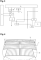
Fig. 3 is a schematic representation of the truck complying with ADR according to one embodiment and -
Fig.4 is top view of a truck complying with ADR according to one embodiment. - The present description is given in an X, Y, Z referential where X is defined as the longitudinal direction of the
vehicle 1, Y is defined as the transversal direction and Z is defined as the vertical direction of thevehicle 1. -
Figure 1 shows atruck 1 complying with ADR, which is preferably a Diesel truck or more generally a truck equipped with an Internal Combustion Engine (ICE). In a variant not shown, the truck can also be an electric (EV) or hybrid truck vehicle (HEV), i.e. a truck using at least partly electric energy as a source of power. - In the example, the
truck 1 comprises front wheels W1. - The
truck 1 further comprises acab 2 suitably mounted on a chassis and including aninterior space 21 delimited by aright side 22, aleft side 23, a floor (not shown) and aroof 24. In this example, thesolar panel 3 includingsolar cells 31 are provided on saidroof 24. - As shown in
Figures 1 and 2 , thetruck 1 also includes at least onebattery 5 arranged on the chassis. Typically,battery 5 is a 12V or 24V Acid-Lead battery. Advantageously, thesolar cells 31 enable to recharge thebattery 5 even when the ICE is off, for example when the truck is parked. This allows supplementing the battery especially for the case in which the occupant/driver of the vehicles uses greedy electrical devices at night, such as HVAC, phone/tablet chargers, TV, fridge and so on. In variant, thebattery 5 may also be a Lithiumion battery (for an electric truck). - The
truck 1 comprises acrash sensor 4 for detecting a crash situation and sending a signal of a crash situation to the electronic control unit (not shown). The electronic control unit then disconnects the second relay in case of crash situation. Thecrash sensor 4 may be an accelerometer capable of detecting a steep deceleration characteristic of a crash. - For example, the truck comprises at least two airbags between the occupants and hard surfaces, for example the dashboard and/or the steering wheel, within the vehicle, which diffuse the energy of the crash across a wider area. Another crash sensor may trigger the inflation of the airbag upon rapid deceleration, and within seconds allows the airbag to deflate.
- Alternatively, a unique crash sensor is used to detect a crash situation and to automatically disconnect the second relay in case of crash situation and to trigger the inflation of airbags.
- A
first relay 6, which is better known as "master switch", is provided to disconnect thebattery 5, i.e. electrically isolate the battery. - A
second relay 7 is provided to disconnect thesolar panel 3. Thesecond relay 7 is distinctive from thefirst relay 6. According to the present invention, the terms "disconnect" and "isolate" refer to the action of isolating thebattery 5 orsolar panel 3 from the rest of the electrical network, in particular thebus CAN 8, of the vehicle. - For example, first and
second relays relays - In this example, the
crash sensor 4 comprises a moving element, such as a ball, configured to close one electrical terminal, typically the negative terminal (mass) of the second relay, so that, in a crash situation, the displacement of moving element opens the mass of second relay. - Another
manual control element 11 can be provided on vehicle chassis. Thismanual control element 11 can be operated by the firemen, which induces firstly the disconnection of thebattery 5 and secondly, almost simultaneously, the disconnection of the solar panel(s) 3. - A
voltage converter 9 may be located between thesolar panel 3 and thebattery 5. Thevoltage converter 9 transforms the voltage generated by thesolar panel 3, for example about 50V, into a lower voltage power, for example 12V or 24V, which is used to charge thebattery 5. - Usually, in case of a vehicle accident, firemen manually disconnect the vehicle battery before starting rescue operations. However, there is no way to disconnect the solar panel(s) since it is rare to install solar panels on trucks. Thus, there is a risk of explosions and fires. The truck adapted to transport Dangerous Goods according to the invention solves this problem by providing a system that automatically disconnects the solar panel when a crash situation is detected.
- According to the present invention, when a crash situation is detected by the
crash sensor 4. Thecrash sensor 4 sends a signal of the crash situation to an Electronic Control Unit ECU (not shown). The electronic control unit then opens thesecond relay 7 by sending the appropriate control signal torelay 7. Thesecond relay 7 is thus open, thereby disconnectingsolar panel 3. - Firemen can disconnect the
battery 5 by disconnecting the battery terminals. In variant, firemen can disconnect thebattery 5 by operating a manual control element 12 (if any) provided on the chassis in close proximity to thebattery 5. In this case, the operation ofcontrol element 12 leads to the opening of thefirst relay 6 which in turn, leads to battery disconnection. - In addition, and in order to comply with the regulation in respect of the transport of Dangerous Goods by road, the
manual control element 11 provided inside thetruck cab 2 allows the driver to disconnect simultaneously thebattery 5 andsolar panel 3. Thus, saidmanual control element 11 may be used by the driver when parking inside a risky site, also known as SEVESO site. Cutting off all electric sources of the vehicle enables to make sure that there is no static electricity remaining and accordingly it prevents the apparition of a spark that may lead to an explosion or a fire in case of gas leak coming from outside of the vehicle. - When another
manual control element 12 is provided on vehicle chassis, it can be operated by the firemen, which induces firstly the disconnection of thebattery 5 and secondly, almost simultaneously, the disconnection of the solar panel(s) 3. Indeed, bothrelays CAN bus 8, which means that, if for any reason,second relay 7 is still closed when firemen arrive on crash location,relay 7 subsequently to the opening offirst relay 6. In detail, before starting rescue operations, firemen operatemanual control element 12, which triggers the opening offirst relay 6. In turn, this information is sent through theCAN bus 8, which involves the opening of second relay 7 (if still closed after crash). Obviously, a reaction time exists, which means that the terms "almost simultaneously" mean that second disconnection occurs a few milliseconds after first disconnection. - This is the advantage of having a
manual control element 12 in close proximity to thebattery 5. It allows the firemen to manually open bothrelays manual control element 12 remains optional as, normally,second relay 7 is automatically opened after a crash has occurred, which means that firemen normally only need to disconnect thevehicle battery 5 associated tofirst relay 6. - According to the present invention, a method for the management of the
truck 1 comprises a step A) wherein thecrash sensor 4 detects a crash situation while the truck is in motion. Thecrash sensor 4 sends a signal of the crash situation to the electronic control unit. - As shown in
Figure 3 , in case of emergency situation, in a step B), the electronic control unit disconnects thesecond relay 7. Thesecond relay 7 disconnects thesolar panel 3. In step C), themanual control 12 opens thefirst relay 6 to manually disconnect thebattery 5. - In one embodiment, step C) is performed before step B). Preferably, in step C), the manual opening of the
first relay 6 leads to the opening of thesecond relay 7. - Alternatively, in step B), the
second relay 7 is opened during a crash situation. Preferably, thesecond relay 7 is opened during a crash situation. - As shown in
Figure 4 , thesolar panel 3 is configured to match the deflector outside surface. In particular, the shape of thesolar panel 3 is adapted to match the shape of thedeflector 25. - By the provision of the truck and the method for the management of said truck according to the present invention, the advantage is to significantly improve the safety of the driver of the driver, surrounding people and emergency services in case of emergency situation.
- It is to be understood that the present invention is not limited to the embodiments described above and illustrated in the drawings; rather, the skilled person will recognize that many changes and modifications may be made within the scope of the appended claims.
Claims (11)
- A truck (1) adapted to transport Dangerous Goods, the truck being characterized in that it comprises:- a chassis on which is arranged a battery (5);- a cab (2) mounted on the chassis,- a solar panel (3) for charging the battery (5), said solar panel (3) being arranged on cab roof (24);- a first relay (6) configured to disconnect the battery (5) and a second relay (7), distinctive from the first relay (6), configured to disconnect the solar panel (3);- at least one manual control element (12), located inside the cab (2), configured to simultaneously open the first (6) and second (7) relays,- a crash sensor (4) for detecting a crash situation; and- an electronic control unit which is connected between the crash sensor (4) and the second relay (7), said electronic control unit being configured to open second relay (7) when it receives a signal from the crash sensor (4) corresponding to a crash situation.
- The truck (1) according to claim 1, wherein the crash sensor (4) is an accelerometer comprising a moving element, such as a ball, configured to close one electrical terminal of the second relay, so that, in a crash situation, the displacement of moving element opens said electrical terminal of second relay.
- The truck (1) according to claim 1 or 2, wherein the crash sensor (4) is located inside the cab (4).
- The truck (1) according to any of the preceding claims, characterized in that the truck includes another manual control element (11) located on the chassis configured to simultaneously open the first (6) and second (7) relays.
- The truck (1) according to any of the preceding claims, wherein the truck comprises a converter (9) located between the solar panel (3) and the battery (5).
- The truck (1) according to any of the preceding claims, wherein the solar panel (3) is configured to match a cab deflector (25).
- A method for the management of a truck (1) according to any one of the preceding claims, said method comprising the following steps:A. Detecting a crash situation while the truck (1) is in motion using the crash sensor (4) and sending a signal of the crash situation to the electronic control unit,B. Disconnecting the solar panel (3) through the second relay (7) using the electronic control unit,C. Manually disconnecting the battery (5) through the first relay (6) using at least one manual control element (12).
- The method for the management of the truck (1) according to claim 7, wherein step C) is performed before step B).
- The method according for the management of the truck (1) to claim 8, wherein in step C), the manual opening of the first relay (6) leads to the opening of the second relay (7).
- The method for the management of the truck (1) according to claim 7, wherein in step B), the second relay (7) is opened during a crash situation.
- The method for the management of the truck (1) according to claim 8, wherein in step B), the electronic control unit opens the second relay (7).
Priority Applications (3)
| Application Number | Priority Date | Filing Date | Title |
|---|---|---|---|
| EP21209364.5A EP4184458B1 (en) | 2021-11-19 | 2021-11-19 | A truck complying with the agreement concerning the international carriage of dangerous goods by road (adr) |
| US18/056,543 US20230158978A1 (en) | 2021-11-19 | 2022-11-17 | Truck complying with the agreement concerning the international carriage of dangerous goods by road (adr) |
| CN202211444323.0A CN116279232A (en) | 2021-11-19 | 2022-11-18 | ADR-compliant trucks |
Applications Claiming Priority (1)
| Application Number | Priority Date | Filing Date | Title |
|---|---|---|---|
| EP21209364.5A EP4184458B1 (en) | 2021-11-19 | 2021-11-19 | A truck complying with the agreement concerning the international carriage of dangerous goods by road (adr) |
Publications (2)
| Publication Number | Publication Date |
|---|---|
| EP4184458A1 true EP4184458A1 (en) | 2023-05-24 |
| EP4184458B1 EP4184458B1 (en) | 2024-10-23 |
Family
ID=78821729
Family Applications (1)
| Application Number | Title | Priority Date | Filing Date |
|---|---|---|---|
| EP21209364.5A Active EP4184458B1 (en) | 2021-11-19 | 2021-11-19 | A truck complying with the agreement concerning the international carriage of dangerous goods by road (adr) |
Country Status (3)
| Country | Link |
|---|---|
| US (1) | US20230158978A1 (en) |
| EP (1) | EP4184458B1 (en) |
| CN (1) | CN116279232A (en) |
Citations (3)
| Publication number | Priority date | Publication date | Assignee | Title |
|---|---|---|---|---|
| US20080143292A1 (en) * | 2005-08-24 | 2008-06-19 | Ward Thomas A | Hybrid vehicle with a low voltage solar panel charging a high voltage battery using a series charger to separately charge individual cells of the series connected battery |
| US20100263947A1 (en) * | 2009-04-20 | 2010-10-21 | Chris John Reichart | Method for generating electricity from solar panels for an electrical system inside a truck/semi/vehicle |
| US20180056769A1 (en) * | 2016-08-29 | 2018-03-01 | Koenig Metall Gmbh & Co. Kg | Electric truck |
-
2021
- 2021-11-19 EP EP21209364.5A patent/EP4184458B1/en active Active
-
2022
- 2022-11-17 US US18/056,543 patent/US20230158978A1/en not_active Abandoned
- 2022-11-18 CN CN202211444323.0A patent/CN116279232A/en active Pending
Patent Citations (3)
| Publication number | Priority date | Publication date | Assignee | Title |
|---|---|---|---|---|
| US20080143292A1 (en) * | 2005-08-24 | 2008-06-19 | Ward Thomas A | Hybrid vehicle with a low voltage solar panel charging a high voltage battery using a series charger to separately charge individual cells of the series connected battery |
| US20100263947A1 (en) * | 2009-04-20 | 2010-10-21 | Chris John Reichart | Method for generating electricity from solar panels for an electrical system inside a truck/semi/vehicle |
| US20180056769A1 (en) * | 2016-08-29 | 2018-03-01 | Koenig Metall Gmbh & Co. Kg | Electric truck |
Also Published As
| Publication number | Publication date |
|---|---|
| US20230158978A1 (en) | 2023-05-25 |
| CN116279232A (en) | 2023-06-23 |
| EP4184458B1 (en) | 2024-10-23 |
Similar Documents
| Publication | Publication Date | Title |
|---|---|---|
| JP6308225B2 (en) | In-vehicle power supply system | |
| JP4330274B2 (en) | Battery-mounted power system with safety protection disconnection device | |
| CN105691209B (en) | The electric automobile electrical system of controller and redundancy of powering with distributed structure/architecture | |
| US6528899B1 (en) | Power supply network apparatus | |
| US20090243554A1 (en) | Method of protecting battery for hybrid vehicle | |
| US11173858B2 (en) | Vehicle power supply system | |
| CN116605164B (en) | Vehicles and their electrical systems | |
| KR20230151591A (en) | Power management device and vehicle | |
| EP2258579B1 (en) | Additional autonomous power supply system for vehicle, especially for industrial or commercial vehicle | |
| JP2003165406A (en) | Vehicle power supply system | |
| CN205706189U (en) | The controller of distributed structure/architecture and power supply redundancy electronic intelligent automobile electrical system | |
| US7266441B2 (en) | System and method for controlling idling stop of hybrid electric vehicle | |
| US20250229633A1 (en) | Means of Transport, Driver Assistance System and Method for Handling a Breakdown Situation | |
| KR20240144202A (en) | Battery management system, electric vehicle, method and control unit | |
| EP4184458B1 (en) | A truck complying with the agreement concerning the international carriage of dangerous goods by road (adr) | |
| CN217532573U (en) | High-voltage power-off system for vehicle and vehicle | |
| CN110803024B (en) | Collision protection control method and system for electric vehicle | |
| CN103660952A (en) | Over-current damage prevention method and apparatus for subsidiary inverter of electric bus | |
| CN223533450U (en) | Power distribution system and vehicle | |
| US20250346123A1 (en) | Multi-zonal vehicle architecture | |
| US20250343411A1 (en) | Electronic control unit jumpstart feature for electric vehicles | |
| US20260116200A1 (en) | Adaptive hardware safety disconnect system | |
| US20030107861A1 (en) | Method and apparatus for disconnecting a battery | |
| CN115716416A (en) | vehicle | |
| JPH0769039A (en) | Vehicle heat pump type air conditioner |
Legal Events
| Date | Code | Title | Description |
|---|---|---|---|
| PUAI | Public reference made under article 153(3) epc to a published international application that has entered the european phase |
Free format text: ORIGINAL CODE: 0009012 |
|
| STAA | Information on the status of an ep patent application or granted ep patent |
Free format text: STATUS: THE APPLICATION HAS BEEN PUBLISHED |
|
| AK | Designated contracting states |
Kind code of ref document: A1 Designated state(s): AL AT BE BG CH CY CZ DE DK EE ES FI FR GB GR HR HU IE IS IT LI LT LU LV MC MK MT NL NO PL PT RO RS SE SI SK SM TR |
|
| STAA | Information on the status of an ep patent application or granted ep patent |
Free format text: STATUS: REQUEST FOR EXAMINATION WAS MADE |
|
| 17P | Request for examination filed |
Effective date: 20231121 |
|
| RBV | Designated contracting states (corrected) |
Designated state(s): AL AT BE BG CH CY CZ DE DK EE ES FI FR GB GR HR HU IE IS IT LI LT LU LV MC MK MT NL NO PL PT RO RS SE SI SK SM TR |
|
| RIC1 | Information provided on ipc code assigned before grant |
Ipc: B60L 50/61 20190101ALI20240517BHEP Ipc: B60L 8/00 20060101ALI20240517BHEP Ipc: B60L 3/04 20060101ALI20240517BHEP Ipc: B60L 3/00 20190101ALI20240517BHEP Ipc: G07C 5/00 20060101AFI20240517BHEP |
|
| GRAP | Despatch of communication of intention to grant a patent |
Free format text: ORIGINAL CODE: EPIDOSNIGR1 |
|
| STAA | Information on the status of an ep patent application or granted ep patent |
Free format text: STATUS: GRANT OF PATENT IS INTENDED |
|
| INTG | Intention to grant announced |
Effective date: 20240712 |
|
| GRAS | Grant fee paid |
Free format text: ORIGINAL CODE: EPIDOSNIGR3 |
|
| GRAA | (expected) grant |
Free format text: ORIGINAL CODE: 0009210 |
|
| STAA | Information on the status of an ep patent application or granted ep patent |
Free format text: STATUS: THE PATENT HAS BEEN GRANTED |
|
| AK | Designated contracting states |
Kind code of ref document: B1 Designated state(s): AL AT BE BG CH CY CZ DE DK EE ES FI FR GB GR HR HU IE IS IT LI LT LU LV MC MK MT NL NO PL PT RO RS SE SI SK SM TR |
|
| REG | Reference to a national code |
Ref country code: GB Ref legal event code: FG4D |
|
| REG | Reference to a national code |
Ref country code: CH Ref legal event code: EP |
|
| REG | Reference to a national code |
Ref country code: DE Ref legal event code: R096 Ref document number: 602021020596 Country of ref document: DE |
|
| REG | Reference to a national code |
Ref country code: IE Ref legal event code: FG4D |
|
| REG | Reference to a national code |
Ref country code: LT Ref legal event code: MG9D |
|
| REG | Reference to a national code |
Ref country code: NL Ref legal event code: MP Effective date: 20241023 |
|
| REG | Reference to a national code |
Ref country code: AT Ref legal event code: MK05 Ref document number: 1735486 Country of ref document: AT Kind code of ref document: T Effective date: 20241023 |
|
| PG25 | Lapsed in a contracting state [announced via postgrant information from national office to epo] |
Ref country code: NL Free format text: LAPSE BECAUSE OF FAILURE TO SUBMIT A TRANSLATION OF THE DESCRIPTION OR TO PAY THE FEE WITHIN THE PRESCRIBED TIME-LIMIT Effective date: 20241023 |
|
| PG25 | Lapsed in a contracting state [announced via postgrant information from national office to epo] |
Ref country code: NL Free format text: LAPSE BECAUSE OF FAILURE TO SUBMIT A TRANSLATION OF THE DESCRIPTION OR TO PAY THE FEE WITHIN THE PRESCRIBED TIME-LIMIT Effective date: 20241023 |
|
| PG25 | Lapsed in a contracting state [announced via postgrant information from national office to epo] |
Ref country code: HR Free format text: LAPSE BECAUSE OF FAILURE TO SUBMIT A TRANSLATION OF THE DESCRIPTION OR TO PAY THE FEE WITHIN THE PRESCRIBED TIME-LIMIT Effective date: 20241023 Ref country code: PT Free format text: LAPSE BECAUSE OF FAILURE TO SUBMIT A TRANSLATION OF THE DESCRIPTION OR TO PAY THE FEE WITHIN THE PRESCRIBED TIME-LIMIT Effective date: 20250224 Ref country code: IS Free format text: LAPSE BECAUSE OF FAILURE TO SUBMIT A TRANSLATION OF THE DESCRIPTION OR TO PAY THE FEE WITHIN THE PRESCRIBED TIME-LIMIT Effective date: 20250223 |
|
| PG25 | Lapsed in a contracting state [announced via postgrant information from national office to epo] |
Ref country code: FI Free format text: LAPSE BECAUSE OF FAILURE TO SUBMIT A TRANSLATION OF THE DESCRIPTION OR TO PAY THE FEE WITHIN THE PRESCRIBED TIME-LIMIT Effective date: 20241023 |
|
| PG25 | Lapsed in a contracting state [announced via postgrant information from national office to epo] |
Ref country code: BG Free format text: LAPSE BECAUSE OF FAILURE TO SUBMIT A TRANSLATION OF THE DESCRIPTION OR TO PAY THE FEE WITHIN THE PRESCRIBED TIME-LIMIT Effective date: 20241023 |
|
| PG25 | Lapsed in a contracting state [announced via postgrant information from national office to epo] |
Ref country code: ES Free format text: LAPSE BECAUSE OF FAILURE TO SUBMIT A TRANSLATION OF THE DESCRIPTION OR TO PAY THE FEE WITHIN THE PRESCRIBED TIME-LIMIT Effective date: 20241023 |
|
| PG25 | Lapsed in a contracting state [announced via postgrant information from national office to epo] |
Ref country code: NO Free format text: LAPSE BECAUSE OF FAILURE TO SUBMIT A TRANSLATION OF THE DESCRIPTION OR TO PAY THE FEE WITHIN THE PRESCRIBED TIME-LIMIT Effective date: 20250123 |
|
| PG25 | Lapsed in a contracting state [announced via postgrant information from national office to epo] |
Ref country code: GR Free format text: LAPSE BECAUSE OF FAILURE TO SUBMIT A TRANSLATION OF THE DESCRIPTION OR TO PAY THE FEE WITHIN THE PRESCRIBED TIME-LIMIT Effective date: 20250124 Ref country code: LV Free format text: LAPSE BECAUSE OF FAILURE TO SUBMIT A TRANSLATION OF THE DESCRIPTION OR TO PAY THE FEE WITHIN THE PRESCRIBED TIME-LIMIT Effective date: 20241023 Ref country code: AT Free format text: LAPSE BECAUSE OF FAILURE TO SUBMIT A TRANSLATION OF THE DESCRIPTION OR TO PAY THE FEE WITHIN THE PRESCRIBED TIME-LIMIT Effective date: 20241023 |
|
| PG25 | Lapsed in a contracting state [announced via postgrant information from national office to epo] |
Ref country code: PL Free format text: LAPSE BECAUSE OF FAILURE TO SUBMIT A TRANSLATION OF THE DESCRIPTION OR TO PAY THE FEE WITHIN THE PRESCRIBED TIME-LIMIT Effective date: 20241023 |
|
| PG25 | Lapsed in a contracting state [announced via postgrant information from national office to epo] |
Ref country code: RS Free format text: LAPSE BECAUSE OF FAILURE TO SUBMIT A TRANSLATION OF THE DESCRIPTION OR TO PAY THE FEE WITHIN THE PRESCRIBED TIME-LIMIT Effective date: 20250123 |
|
| REG | Reference to a national code |
Ref country code: DE Ref legal event code: R119 Ref document number: 602021020596 Country of ref document: DE |
|
| REG | Reference to a national code |
Ref country code: CH Ref legal event code: PL |
|
| PG25 | Lapsed in a contracting state [announced via postgrant information from national office to epo] |
Ref country code: SM Free format text: LAPSE BECAUSE OF FAILURE TO SUBMIT A TRANSLATION OF THE DESCRIPTION OR TO PAY THE FEE WITHIN THE PRESCRIBED TIME-LIMIT Effective date: 20241023 |
|
| PG25 | Lapsed in a contracting state [announced via postgrant information from national office to epo] |
Ref country code: MC Free format text: LAPSE BECAUSE OF FAILURE TO SUBMIT A TRANSLATION OF THE DESCRIPTION OR TO PAY THE FEE WITHIN THE PRESCRIBED TIME-LIMIT Effective date: 20241023 |
|
| PG25 | Lapsed in a contracting state [announced via postgrant information from national office to epo] |
Ref country code: DK Free format text: LAPSE BECAUSE OF FAILURE TO SUBMIT A TRANSLATION OF THE DESCRIPTION OR TO PAY THE FEE WITHIN THE PRESCRIBED TIME-LIMIT Effective date: 20241023 |
|
| PG25 | Lapsed in a contracting state [announced via postgrant information from national office to epo] |
Ref country code: LU Free format text: LAPSE BECAUSE OF NON-PAYMENT OF DUE FEES Effective date: 20241119 |
|
| REG | Reference to a national code |
Ref country code: CH Ref legal event code: PL |
|
| PG25 | Lapsed in a contracting state [announced via postgrant information from national office to epo] |
Ref country code: EE Free format text: LAPSE BECAUSE OF FAILURE TO SUBMIT A TRANSLATION OF THE DESCRIPTION OR TO PAY THE FEE WITHIN THE PRESCRIBED TIME-LIMIT Effective date: 20241023 |
|
| PG25 | Lapsed in a contracting state [announced via postgrant information from national office to epo] |
Ref country code: CH Free format text: LAPSE BECAUSE OF NON-PAYMENT OF DUE FEES Effective date: 20241130 |
|
| PG25 | Lapsed in a contracting state [announced via postgrant information from national office to epo] |
Ref country code: RO Free format text: LAPSE BECAUSE OF FAILURE TO SUBMIT A TRANSLATION OF THE DESCRIPTION OR TO PAY THE FEE WITHIN THE PRESCRIBED TIME-LIMIT Effective date: 20241023 |
|
| PG25 | Lapsed in a contracting state [announced via postgrant information from national office to epo] |
Ref country code: SK Free format text: LAPSE BECAUSE OF FAILURE TO SUBMIT A TRANSLATION OF THE DESCRIPTION OR TO PAY THE FEE WITHIN THE PRESCRIBED TIME-LIMIT Effective date: 20241023 |
|
| PG25 | Lapsed in a contracting state [announced via postgrant information from national office to epo] |
Ref country code: CZ Free format text: LAPSE BECAUSE OF FAILURE TO SUBMIT A TRANSLATION OF THE DESCRIPTION OR TO PAY THE FEE WITHIN THE PRESCRIBED TIME-LIMIT Effective date: 20241023 |
|
| PG25 | Lapsed in a contracting state [announced via postgrant information from national office to epo] |
Ref country code: IT Free format text: LAPSE BECAUSE OF FAILURE TO SUBMIT A TRANSLATION OF THE DESCRIPTION OR TO PAY THE FEE WITHIN THE PRESCRIBED TIME-LIMIT Effective date: 20241023 |
|
| REG | Reference to a national code |
Ref country code: BE Ref legal event code: MM Effective date: 20241130 |
|
| PLBE | No opposition filed within time limit |
Free format text: ORIGINAL CODE: 0009261 |
|
| STAA | Information on the status of an ep patent application or granted ep patent |
Free format text: STATUS: NO OPPOSITION FILED WITHIN TIME LIMIT |
|
| PG25 | Lapsed in a contracting state [announced via postgrant information from national office to epo] |
Ref country code: SE Free format text: LAPSE BECAUSE OF FAILURE TO SUBMIT A TRANSLATION OF THE DESCRIPTION OR TO PAY THE FEE WITHIN THE PRESCRIBED TIME-LIMIT Effective date: 20241023 |
|
| 26N | No opposition filed |
Effective date: 20250724 |
|
| PG25 | Lapsed in a contracting state [announced via postgrant information from national office to epo] |
Ref country code: DE Free format text: LAPSE BECAUSE OF NON-PAYMENT OF DUE FEES Effective date: 20250603 |
|
| PG25 | Lapsed in a contracting state [announced via postgrant information from national office to epo] |
Ref country code: BE Free format text: LAPSE BECAUSE OF NON-PAYMENT OF DUE FEES Effective date: 20241130 |
|
| PG25 | Lapsed in a contracting state [announced via postgrant information from national office to epo] |
Ref country code: FR Free format text: LAPSE BECAUSE OF NON-PAYMENT OF DUE FEES Effective date: 20241223 |
|
| PG25 | Lapsed in a contracting state [announced via postgrant information from national office to epo] |
Ref country code: IE Free format text: LAPSE BECAUSE OF NON-PAYMENT OF DUE FEES Effective date: 20241119 |
|
| PG25 | Lapsed in a contracting state [announced via postgrant information from national office to epo] |
Ref country code: HU Free format text: LAPSE BECAUSE OF FAILURE TO SUBMIT A TRANSLATION OF THE DESCRIPTION OR TO PAY THE FEE WITHIN THE PRESCRIBED TIME-LIMIT; INVALID AB INITIO Effective date: 20211119 |
|
| PG25 | Lapsed in a contracting state [announced via postgrant information from national office to epo] |
Ref country code: CY Free format text: LAPSE BECAUSE OF FAILURE TO SUBMIT A TRANSLATION OF THE DESCRIPTION OR TO PAY THE FEE WITHIN THE PRESCRIBED TIME-LIMIT; INVALID AB INITIO Effective date: 20211119 |