EP4184214A1 - Movement prediction device - Google Patents
Movement prediction device Download PDFInfo
- Publication number
- EP4184214A1 EP4184214A1 EP21923121.4A EP21923121A EP4184214A1 EP 4184214 A1 EP4184214 A1 EP 4184214A1 EP 21923121 A EP21923121 A EP 21923121A EP 4184214 A1 EP4184214 A1 EP 4184214A1
- Authority
- EP
- European Patent Office
- Prior art keywords
- light
- rotor wing
- flying object
- movement
- distance
- Prior art date
- Legal status (The legal status is an assumption and is not a legal conclusion. Google has not performed a legal analysis and makes no representation as to the accuracy of the status listed.)
- Granted
Links
Images






Classifications
-
- B—PERFORMING OPERATIONS; TRANSPORTING
- B64—AIRCRAFT; AVIATION; COSMONAUTICS
- B64U—UNMANNED AERIAL VEHICLES [UAV]; EQUIPMENT THEREFOR
- B64U10/00—Type of UAV
- B64U10/10—Rotorcrafts
- B64U10/13—Flying platforms
-
- B—PERFORMING OPERATIONS; TRANSPORTING
- B64—AIRCRAFT; AVIATION; COSMONAUTICS
- B64U—UNMANNED AERIAL VEHICLES [UAV]; EQUIPMENT THEREFOR
- B64U30/00—Means for producing lift; Empennages; Arrangements thereof
- B64U30/20—Rotors; Rotor supports
- B64U30/21—Rotary wings
-
- G—PHYSICS
- G01—MEASURING; TESTING
- G01P—MEASURING LINEAR OR ANGULAR SPEED, ACCELERATION, DECELERATION, OR SHOCK; INDICATING PRESENCE, ABSENCE, OR DIRECTION, OF MOVEMENT
- G01P3/00—Measuring linear or angular speed; Measuring differences of linear or angular speeds
- G01P3/36—Devices characterised by the use of optical means, e.g. using infrared, visible, or ultraviolet light
-
- G—PHYSICS
- G01—MEASURING; TESTING
- G01S—RADIO DIRECTION-FINDING; RADIO NAVIGATION; DETERMINING DISTANCE OR VELOCITY BY USE OF RADIO WAVES; LOCATING OR PRESENCE-DETECTING BY USE OF THE REFLECTION OR RERADIATION OF RADIO WAVES; ANALOGOUS ARRANGEMENTS USING OTHER WAVES
- G01S17/00—Systems using the reflection or reradiation of electromagnetic waves other than radio waves, e.g. lidar systems
- G01S17/02—Systems using the reflection of electromagnetic waves other than radio waves
- G01S17/06—Systems determining position data of a target
- G01S17/08—Systems determining position data of a target for measuring distance only
- G01S17/10—Systems determining position data of a target for measuring distance only using transmission of interrupted, pulse-modulated waves
-
- G—PHYSICS
- G01—MEASURING; TESTING
- G01S—RADIO DIRECTION-FINDING; RADIO NAVIGATION; DETERMINING DISTANCE OR VELOCITY BY USE OF RADIO WAVES; LOCATING OR PRESENCE-DETECTING BY USE OF THE REFLECTION OR RERADIATION OF RADIO WAVES; ANALOGOUS ARRANGEMENTS USING OTHER WAVES
- G01S17/00—Systems using the reflection or reradiation of electromagnetic waves other than radio waves, e.g. lidar systems
- G01S17/02—Systems using the reflection of electromagnetic waves other than radio waves
- G01S17/06—Systems determining position data of a target
- G01S17/42—Simultaneous measurement of distance and other co-ordinates
-
- G—PHYSICS
- G01—MEASURING; TESTING
- G01S—RADIO DIRECTION-FINDING; RADIO NAVIGATION; DETERMINING DISTANCE OR VELOCITY BY USE OF RADIO WAVES; LOCATING OR PRESENCE-DETECTING BY USE OF THE REFLECTION OR RERADIATION OF RADIO WAVES; ANALOGOUS ARRANGEMENTS USING OTHER WAVES
- G01S17/00—Systems using the reflection or reradiation of electromagnetic waves other than radio waves, e.g. lidar systems
- G01S17/02—Systems using the reflection of electromagnetic waves other than radio waves
- G01S17/50—Systems of measurement based on relative movement of target
-
- G—PHYSICS
- G01—MEASURING; TESTING
- G01S—RADIO DIRECTION-FINDING; RADIO NAVIGATION; DETERMINING DISTANCE OR VELOCITY BY USE OF RADIO WAVES; LOCATING OR PRESENCE-DETECTING BY USE OF THE REFLECTION OR RERADIATION OF RADIO WAVES; ANALOGOUS ARRANGEMENTS USING OTHER WAVES
- G01S17/00—Systems using the reflection or reradiation of electromagnetic waves other than radio waves, e.g. lidar systems
- G01S17/66—Tracking systems using electromagnetic waves other than radio waves
-
- G—PHYSICS
- G01—MEASURING; TESTING
- G01S—RADIO DIRECTION-FINDING; RADIO NAVIGATION; DETERMINING DISTANCE OR VELOCITY BY USE OF RADIO WAVES; LOCATING OR PRESENCE-DETECTING BY USE OF THE REFLECTION OR RERADIATION OF RADIO WAVES; ANALOGOUS ARRANGEMENTS USING OTHER WAVES
- G01S17/00—Systems using the reflection or reradiation of electromagnetic waves other than radio waves, e.g. lidar systems
- G01S17/86—Combinations of lidar systems with systems other than lidar, radar or sonar, e.g. with direction finders
-
- G—PHYSICS
- G01—MEASURING; TESTING
- G01S—RADIO DIRECTION-FINDING; RADIO NAVIGATION; DETERMINING DISTANCE OR VELOCITY BY USE OF RADIO WAVES; LOCATING OR PRESENCE-DETECTING BY USE OF THE REFLECTION OR RERADIATION OF RADIO WAVES; ANALOGOUS ARRANGEMENTS USING OTHER WAVES
- G01S7/00—Details of systems according to groups G01S13/00, G01S15/00, G01S17/00
- G01S7/48—Details of systems according to groups G01S13/00, G01S15/00, G01S17/00 of systems according to group G01S17/00
- G01S7/4802—Details of systems according to groups G01S13/00, G01S15/00, G01S17/00 of systems according to group G01S17/00 using analysis of echo signal for target characterisation; Target signature; Target cross-section
-
- G—PHYSICS
- G01—MEASURING; TESTING
- G01S—RADIO DIRECTION-FINDING; RADIO NAVIGATION; DETERMINING DISTANCE OR VELOCITY BY USE OF RADIO WAVES; LOCATING OR PRESENCE-DETECTING BY USE OF THE REFLECTION OR RERADIATION OF RADIO WAVES; ANALOGOUS ARRANGEMENTS USING OTHER WAVES
- G01S7/00—Details of systems according to groups G01S13/00, G01S15/00, G01S17/00
- G01S7/48—Details of systems according to groups G01S13/00, G01S15/00, G01S17/00 of systems according to group G01S17/00
- G01S7/4808—Evaluating distance, position or velocity data
-
- G—PHYSICS
- G01—MEASURING; TESTING
- G01S—RADIO DIRECTION-FINDING; RADIO NAVIGATION; DETERMINING DISTANCE OR VELOCITY BY USE OF RADIO WAVES; LOCATING OR PRESENCE-DETECTING BY USE OF THE REFLECTION OR RERADIATION OF RADIO WAVES; ANALOGOUS ARRANGEMENTS USING OTHER WAVES
- G01S7/00—Details of systems according to groups G01S13/00, G01S15/00, G01S17/00
- G01S7/48—Details of systems according to groups G01S13/00, G01S15/00, G01S17/00 of systems according to group G01S17/00
- G01S7/481—Constructional features, e.g. arrangements of optical elements
- G01S7/4814—Constructional features, e.g. arrangements of optical elements of transmitters alone
- G01S7/4815—Constructional features, e.g. arrangements of optical elements of transmitters alone using multiple transmitters
-
- G—PHYSICS
- G01—MEASURING; TESTING
- G01S—RADIO DIRECTION-FINDING; RADIO NAVIGATION; DETERMINING DISTANCE OR VELOCITY BY USE OF RADIO WAVES; LOCATING OR PRESENCE-DETECTING BY USE OF THE REFLECTION OR RERADIATION OF RADIO WAVES; ANALOGOUS ARRANGEMENTS USING OTHER WAVES
- G01S7/00—Details of systems according to groups G01S13/00, G01S15/00, G01S17/00
- G01S7/48—Details of systems according to groups G01S13/00, G01S15/00, G01S17/00 of systems according to group G01S17/00
- G01S7/483—Details of pulse systems
- G01S7/486—Receivers
- G01S7/4865—Time delay measurement, e.g. time-of-flight measurement, time of arrival measurement or determining the exact position of a peak
-
- G—PHYSICS
- G01—MEASURING; TESTING
- G01S—RADIO DIRECTION-FINDING; RADIO NAVIGATION; DETERMINING DISTANCE OR VELOCITY BY USE OF RADIO WAVES; LOCATING OR PRESENCE-DETECTING BY USE OF THE REFLECTION OR RERADIATION OF RADIO WAVES; ANALOGOUS ARRANGEMENTS USING OTHER WAVES
- G01S7/00—Details of systems according to groups G01S13/00, G01S15/00, G01S17/00
- G01S7/48—Details of systems according to groups G01S13/00, G01S15/00, G01S17/00 of systems according to group G01S17/00
- G01S7/483—Details of pulse systems
- G01S7/486—Receivers
- G01S7/487—Extracting wanted echo signals, e.g. pulse detection
-
- B—PERFORMING OPERATIONS; TRANSPORTING
- B64—AIRCRAFT; AVIATION; COSMONAUTICS
- B64U—UNMANNED AERIAL VEHICLES [UAV]; EQUIPMENT THEREFOR
- B64U10/00—Type of UAV
- B64U10/10—Rotorcrafts
- B64U10/13—Flying platforms
- B64U10/14—Flying platforms with four distinct rotor axes, e.g. quadcopters
-
- B—PERFORMING OPERATIONS; TRANSPORTING
- B64—AIRCRAFT; AVIATION; COSMONAUTICS
- B64U—UNMANNED AERIAL VEHICLES [UAV]; EQUIPMENT THEREFOR
- B64U30/00—Means for producing lift; Empennages; Arrangements thereof
- B64U30/20—Rotors; Rotor supports
Definitions
- the present invention relates to a movement prediction apparatus.
- Patent Literature 1 discloses an image data processor that periodically captures images of a mobile object and predicts a movement of the mobile object based on the captured images.
- Patent Literature 2 and Non-Patent Literature 1 disclose methods of using two optical frequency combs.
- Non-Patent Literature 1 Zebin Zhu et al., “Dual-Comb Ranging", (on line), October 2018, Elsevier, [Searched on October 21, 2020], Internet (URL: https://www.sciencedirect.com/science/article/pii/S2095809918303783 )
- an objective is to provide a movement prediction apparatus that can predict a movement of a flying object with high accuracy.
- a movement prediction apparatus in order to achieve the above objective is provided with a first light output device, a second light output device, a light reception device, and a processor.
- the first light output device outputs output-light having a spectral component of a first optical frequency comb of which a frequency comb interval is a first interval.
- the second light output device outputs reference light having a spectral component of a second optical frequency comb of which a frequency comb is a second interval different from the first interval.
- the light reception device receives first combination light that is a combination of the output-light, reflection light that is the output-light reflected by a first rotor wing of a flying object having a plurality of rotor wings, and reference light, to measure a first distance to the first rotor wing based on the first combination light.
- the processor calculates a first rotation amount that represents a rotational speed of the first rotor wing based on a change amount of the measured first distance, and predicts a movement of the flying object based on a change of the calculated first rotation amount.
- the movement prediction apparatus can predict a movement of a flying object with high accuracy.
- a movement prediction apparatus 100 outputs output-light 310 to a flying object 10 and receives reflection light 320 thereof to predict a movement of the flying object 10 such as an ascent, a descent, a turning, an acceleration, a deceleration, a change of attitude, or the like.
- the flying object 10 has a plurality of rotor wings 11 and controls the movement by changing a number of revolutions per unit of time of the rotor wings, for example.
- the flying object 10 is a small unmanned aerial vehicle (UAV), a multi-copter, or the like.
- the movement prediction apparatus 100 measures a distance to a wing provided to the rotor wings 11 of the flying object 10 to acquire a change amount of the distance.
- the distance from the movement prediction apparatus 100 to the wing periodically changes in accordance to a rotational speed of the rotor wings 11.
- the movement prediction apparatus 100 calculates a rotation amount that represents the rotational speed of the rotor wings 11 based on this change amount of the distance and calculates a change of the rotational speed of the rotor wings 11.
- the movement prediction apparatus 100 predicts the movement of the flying object 10 based on the change of the rotational speed of the rotor wings 11.
- the movement prediction apparatus 100 is communicably connected with an observation device 20.
- the observation device 20 detects a surrounding flying object 10 and transmits information of the detected flying object 10 such as positional information to the movement prediction apparatus 100.
- the observation device 20 includes for example a radar device, an imaging device, or the like.
- the movement prediction apparatus 100 outputs the output-light 310 to the flying object 10 based on the information of the flying object 10 detected by the observation device 20.
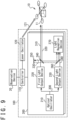
- the movement prediction apparatus 100 is provided with a controller 110 and one or more ranging devices 200.
- a ranging device 200 outputs output-light 310 and receives reflection light 320 from a rotor wing 11 of a flying object 10 to measure a distance from the movement prediction apparatus 100 to the rotor wing 11.
- the controller 110 predicts a movement of the flying object 10 based on the distance from the movement prediction apparatus 100 to the rotor wing 11.
- the controller 110 controls the ranging devices 200 based on the predicted movement of the flying object 10.
- the ranging device 200 is provided with an optical oscillator 210, a first light output device 220, a second light output device 230, a light reception device 270, and a plurality of optical devices such as a first beam splitter 240, a mirror 250, and a second beam splitter 260.
- the optical oscillator 210 is configured to output seed light 300 and irradiate the first light output device 220 and the second light output device 230 with the seed light 300.
- the first light output device 220 is configured to receive the seed light 300 and output the output-light 310.
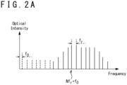
- the output-light 310 has a plurality of frequencies that are lined up by a predetermined frequency interval f r , (this frequency interval will be referred to as comb frequency interval hereinafter) in a frequency domain and referred to as optical comb or optical frequency comb, and has a spectral component with a comb-like shape.
- optical intensity of the output-light 310 having a spectral component as shown in FIG. 2A continuously changes over time as a curved line 900 shown in FIG. 2B .
- Curved lines 910 that connect positions showing local maxima or position showing local minima of the optical intensity that changes over time are similar to pulse waves with a period T r .
- the second light output device 230 is configured to receive the seed light 300 and output reference light 340.
- the reference light 340 has a comb-like shaped spectral component that is referred to as optical comb, similarly to the output-light 310.
- the comb interval f r of the reference light 340 is different from the comb interval f r of the output-light 310.
- the period T r of the reference light 340 is also different from the period T r of the output-light 310.
- the comb interval f r of the reference light 340 is set to approximate the comb interval f r of the output-light 310 and so that an optical beat is generated by combining the reference light 340 and the output-light 310.
- the first beam splitter 240 is configured to split the output-light 310 into two of which one is transmitted and another one is reflected.
- the output-light 310 that has been transmitted through the first beam splitter 240 irradiates the flying object 10.
- the output-light 310 radiated to the flying object 10 is reflected by the flying object 10 as the reflection light 320.
- the reflection light 320 reflected by the flying object 10 incidents into the first beam splitter 240.
- the first beam splitter 240 is configured to reflect the incident reflection light 320 toward the second beam splitter 260.
- the second beam splitter 260 is configured to reflect the reflection light 320 reflected by the first beam splitter 240 toward the light reception device 270.
- the first beam splitter 240 is configured to reflect a part of the output-light 310 toward the mirror 250 as standard light 330.
- the standard light 330 reflected by the first beam splitter 240 is reflected toward the mirror 250 and incidents the second beam splitter 260.
- the second beam splitter 260 reflects the incident standard light 330 toward the light reception device 270.
- the second beam splitter 260 transmits the reference light 340.
- the transmitted reference light 340 incidents the light reception device 270.
- the first beam splitter 240 and the second beam splitter 260 are configured to irradiate the flying object 10 with the output-light 310 that the first light output device 220 outputs and irradiate the light reception device 270 with the reflection light 320 that the flying object 10 reflects.
- the first beam splitter 240, the mirror 250, and the second beam splitter 260 are configured to irradiate the light reception device 270 with the output-light 310 as the standard light 330 that the first light output device 220 outputs.
- the second beam splitter 260 is configured to irradiate the light reception device 270 with the reference light 340 that the second light output device 230 outputs.
- the light reception device 270 receives the combination light that is the combination of the reflection light 320 from the flying object 10, the standard light 330 outputted from the first light output device 220, and the reference light 340 outputted from the second light output device 230.
- the light reception device 270 measures the distance from the ranging device 200 to the flying object 10 based on the received combination light.
- the light reception device 270 measures the distance to the rotor wing 11 of the flying object 10.
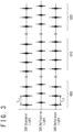
- the standard light 330 is similar to the pulse light with a period T r1
- the reference light 340 is similar to the pulse light with a period T r2 , as shown in FIG. 3 .
- the period T r2 of the reference light 340 approximates the period T r1 of the standard light 330 so that an optical beat is generated when the reference light 340 and the standard light 330 are combined.
- the optical intensity of the combination light in which the reflection light 320, the standard light 330, and the reference light 340 are combined repeats a relatively high state and a relatively low state.
- the optical intensity of the combination light in which the reference light 340 and the standard light 330 are combined becomes relatively high.
- the period T r2 of the reference light 340 is different from the period T r1 of the standard light 330, the more time passes, the waveform of the reference light 340 shifts from the waveform of the standard light 330, and the optical intensity of the combination light becomes relatively low.
- the waveform of the reference light 340 and the waveform of the reflection light 320 overlap and the optical intensity of the combination light becomes relatively high.
- the waveform of the reference light 340 shifts from the waveform of the reflection light 320 and the optical intensity of the combination light becomes relatively low.
- the waveform of the reference light 340 and the waveform of the standard light 330 overlap as in the third state 820 and the optical intensity of the combination light becomes relatively high.
- the light reception device 270 measures the distance from the ranging device 200 and the flying object 10 based on a time from when the waveform of the reflection light 320 and the waveform of the reference light 340 overlap until when the waveform of the standard light 330 and the waveform of the reference light 340 overlap. For example, the light reception device 270 calculates a time of the first state 800 shown in FIG. 3 from when the optical intensity of the combination light in which the reflection light 320, the standard light 330, and the reference light 340 are combined becomes relatively high to a time of the second state 810 when the optical intensity becomes relatively high subsequently. The light reception device 270 measures the distance based on the calculated time. The calculated time represents a time in which time difference between the reflection light 320 and the standard light 330 is increased. As a result, the light reception device 270 can measure the distance with a higher accuracy than measuring the distance based on a time from when the output-light 310 is outputted until when the reflection light 320 is received.
- the controller 110 is provided with an input output device 111, a communication device 112, a storage device 113, and a processor 114.
- the controller 110 is a computer.
- the input output device 111 receives information for the processor 114 to execute processes.
- the input output device 111 outputs result of the processes that the processor 114 executed.
- the input output device 111 includes various input devices and output devices, and includes for example a keyboard, a mouse, a microphone, a display, a speaker, a touch panel, or the like.
- the input output device 111 may be omitted.
- the communication device 112 performs communication with other devices such as the observation device 20, the ranging devices 200, or the like.
- the communication device 112 transfers information received from the observation device 20 and the ranging devices 200 to the processor 114.
- the communication device 112 transfers control signals that the processor 114 generates to the ranging devices 200.
- the communication device 112 includes various interfaces such as a network interface card (NIC), universal serial bus (USB), or the like.
- the storage device 113 stores various data for predicting the movement of the flying object 10 such as a movement prediction program 400.
- the storage device 113 is used as a non-transitory tangible storage medium that memorize the movement prediction program 400.
- the movement prediction program 400 may be provided as a computer program product that is computer-readably stored in a storage medium 1 or may be provided as a computer program product that is downloadable from a server.
- the processor 114 performs various data processes for predicting the movement of the flying object 10.
- the processor 114 reads out from the storage device 113 and executes the movement prediction program 400, and generates control signals for controlling the ranging devices 200.
- the processor 114 includes a central processing unit (CPU) or the like.
- the processor 114 realizes a rotor wing detection section 410, a rotation measurement section 420, and the movement prediction section 430 by executing the movement prediction program 400.
- the rotor wing detection section 410 detects a position where a rotor wing 11 of a flying object 10 exists.
- the rotation measurement section 420 outputs output-light 310 to the detected position of the rotor wing 11 and measures a rotation amount that represents a rotational speed of the rotor wing 11 of the flying object 10.
- the movement prediction section 430 predicts a movement of the flying object 10 based on the measured rotation amount.
- the observation device 20 detects the flying object 10.
- the observation device 20 transmits position information of the detected flying object 10 to the processor 114 of the movement prediction apparatus 100.
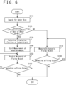
- the processor 114 executes a process of the movement prediction method shown in FIG. 6 by executing the movement prediction program 400.
- the rotor wing detection section 410 that is realized by the processor 114 searches for a position of a rotor wing 11 of a flying object 10. Specifically, the rotor wing detection section 410 transmits a control signal for outputting seed light 300 to the optical oscillator 210. The optical oscillator 210 outputs seed light 300 based on the control signal from the rotor wing detection section 410. In addition, the rotor wing detection section 410 generates a first light output signal for outputting output-light 310 and a second light output signal for outputting reference light 340. The first light output device 220 outputs output-light 310 based on the first light output signal. In addition, the second light output device 230 outputs reference light 340 based on the second light output signal.
- the rotor wing detection section 410 outputs output-light 310 based on the position information of the flying object 10 in order to search for the position where the flying object 10 exists, and searches for the position of the rotor wing 11 of the flying object 10. Specifically, the rotor wing detection section 410 uses a ranging device 200 and measures a distance to a predetermined position of an object in a direction in which the output-light 310 is outputted, such as the flying object 10. The rotor wing detection section 410 detects a position of which the distance that the light reception device 270 measures changes rapidly, continuously, and periodically, as the position of the rotor wing 11.
- a distance from a ranging device 200 to a rotor wing 11 of a flying object 10 changes rapidly, continuously, and periodically over time.
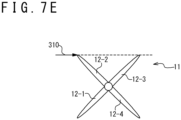
- a ranging device 200 measures a distance to a first wing 12-1 of a rotor wing 11 irradiated with output-light 310.
- the rotor wing 11 rotates for example in a counterclockwise direction shown in the arrow 15.
- FIG. 7B when the rotor wing 11 rotates, the first wing 12-1 moves out from the radiation line of output-light 310 and the output-light 310 irradiates a second wing 12-2. For this reason, in a state of FIG.
- the output-light 310 irradiates a third wing 12-3.
- the rotor wing detection section 410 determines whether a predetermined number or more of rotor wings 11 has been detected. For example, the rotor wing detection section 410 determines whether three or more rotor wings 11 has been detected.
- the process of the step S130 is executed to predict a movement of the flying object 10.
- the process of the step S170 is executed, by determining that the flying object 10 is not controlling a fine movement such as an ascent, a descent, or a turning by the rotor wing 11.
- the rotation measurement section 420 determines an irradiation position to irradiate with the output-light 310. Specifically, the rotation measurement section 420 determines a predetermined position in each region of regions of the plurality of detected rotor wings 11 as an irradiation position. For example, in the region of the detected rotor wing 11, a position at a predetermined distance from the center thereof is determined as the irradiation position.
- the predetermined distance may be determined based on a width size that is the longest length in the region of the rotor wing 11, for example.
- the predetermined distance may be 30% of the width size that is the longest length in the region of the rotor wing 11, for example. It should be noted that the width size of the region of the rotor wing 11 represents a length of a line segment connecting two edges of the region, for example.
- the rotation measurement section 420 starts a measurement of a rotation amount that represents a rotational speed of each rotor wing 11 based on a change amount of the distance that is measured by irradiating each determined irradiation position with the output-light 310.
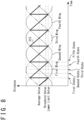
- the distance that the ranging device 200 measures periodically changes within a predetermined range like the curved line 315 in FIG. 8 .
- the first state shown in FIG. 8 represents the state of FIG. 7A and represents a state immediately before the first wing 12-1 moves out from the irradiation line of the output-light 310.
- the second state shown in FIG. 8 represents the state in FIG. 7B : as the second wing 12-2 that is irradiated with the output-light 310 approaches the ranging device 200, the measured distance becomes shorter.
- the third state shown in FIG. 8 represents the state in FIG. 7C and the fourth state shown in FIG. 8 represents the state in FIG. 7D .
- the fifth state shown in FIG. 8 represents the state in FIG. 7E : when the output-light 310 irradiates the second wing 12-2, the measured distance shows the lower limit.
- the measured distance rapidly increases.
- the wing irradiated with the output-light 310 changes to the first wing 12-1, the second wing 12-2, the third wing 12-3, and the fourth wing 12-4 in order.
- the measured distance periodically changes.
- the rotation measurement section 420 measures a rotation amount based on changes of the measured distance. For example, when the rotor wing 11 has four wings, as each of the first wing 12-1 to the fourth wing 12-4 are irradiated with the output-light 310 during one rotation of the rotor wing 11, the measured distance periodically changes four times. When the rotational speed of the rotor wing 11 increases, the time during which the change of the measured distance is repeated four times becomes shorter. As described above, the rotation measurement section 420 measures the rotation amount based on the amount of time required for the change of the measured distance to be repeated a predetermined count of times.
- the count of times, which the change of the measured distance is repeated does not depend on the number of wings that the rotor wing 11 has. For example, even if the rotor wing 11 has five wings, the rotation amount may be measured based on the amount of time required for the change of the measured distance to be repeated four times.
- the rotation measurement section 420 measures the rotation amount based on an amount of time required for a count of times, that the measured distance becomes smaller than a threshold value, to reach a predetermined count of times.
- This threshold value is determined based on a difference between the lower limit value and the average value of the measured distance, as shown in FIG. 8 .
- the threshold value is a value which the average value subtracted with 80% of the difference between the lower limit value and the average value of the measured distance.
- the rotation measurement section 420 counts the times that the measured distance becomes smaller than the threshold value, and measures the amount of time until the count of times reaches a predetermined value, which is four, for example.
- the rotation measurement section 420 calculates an inverse number of the measured amount of time as the rotation amount.
- the average value of the measured distance represents the average value of the distance that is measured during a predetermined period
- the lower limit value represents the shortest distance that is measured during a predetermined period.
- the rotation measurement section 420 determines a rotation direction of the rotor wing 11 based on the change amount of the measured distance. Specifically, the rotation measurement section 420 determines the rotation direction of the rotor wing 11 based on the irradiation position of the output-light 310 in the region of the rotor wing 11 and the change amount of the measured distance. As shown in FIG. 7A , when the irradiation position is in left side of the region of the rotor wing 11 and the rotor wing 11 is rotating in a counterclockwise direction when viewed from above, the measured distance repeats a first state of rapid increase and the second to fourth states of gradual decrease, as shown in FIG. 8 .
- the measured distance repeats a state of rapid decrease and states of gradual increase.
- the measured distance repeats a state of rapid decrease and states of gradual increase.
- the measured distance repeats a state of rapid increase and states of gradual decrease.
- the rotation measurement section 420 determines the rotation direction of the rotor wing 11 by determining whether the irradiation position of the output-light 310 is in left side or right side of the region of the rotor wing 11 and whether an increase or a decrease in the distance that is periodically measured changes relatively rapidly.
- the movement prediction section 430 predicts the movement of the flying object 10 based on the measured rotation amount of each rotor wing 11.
- the movement prediction section 430 determines based on changes of the rotation amount that a force according to the change of the rotation amount is working at the position of the corresponding rotor wing 11. For example, when the rotation amount is increasing, the movement prediction section 430 determines that an upward force is increasing at the position of the corresponding rotor wing 11. In addition, when the rotation amount is decreasing, the movement prediction section 430 determines that a downward force is increasing at the position of the corresponding rotor wing 11.
- the movement prediction section 430 determines forces generated at the position where each rotor wing 11 is arranged and predicts the movement of the flying object 10. For example, when a rotation amount of a rotor wing 11 of a plurality of rotor wings 11 that is in relatively right direction is increasing compared to a rotation amount of a rotor wing 11 that is in relatively left direction, the movement prediction section 430 predicts that the flying object 10 will move to left direction. In addition, when the rotation amount of all rotor wings 11 is increasing, the movement prediction section 430 predicts that the flying object 10 will ascend.
- the movement prediction section 430 predicts that the flying object 10 will turn in counterclockwise direction.
- the rotational speed of a rotor wing 11 that is rotating in clockwise direction when viewed from above is increasing compared to the rotational speed of a rotor wing 11 that is rotating in counterclockwise direction
- the movement prediction section 430 predicts that the flying object 10 will turn in clockwise direction.
- the movement prediction section 430 may determine an attitude of the flying object 10 based on the position of the rotor wing 11 that the ranging section 200 has measured.
- the movement prediction section 430 determines a position in a direction in which the output-light 310 is radiated from the ranging device 200 and at the measured distance as the position of each rotor wing 11.
- the movement prediction section 430 determines an attitude such as an inclination of the flying object 10 based on the position of each rotor wing 11.
- the movement prediction section 430 determines that the flying object 10 is tilted so that right side is lower than left side.
- the movement prediction section 430 may predict the movement of the flying object 10 based on the determined attitude of the flying object 10 and the rotation amount of each rotor wing 11.
- the movement prediction section 430 determines whether the movement prediction section 430 is detecting a flying object 10.
- the process of the step S150 will be executed and the process will be repeated.
- the rotation measurement section 420 changes the position to irradiate with the output-light 310 in accordance with the movement of the flying object 10 that the movement prediction section 430 has predicted. For example, when it is predicted that the flying object 10 will move to left, the rotation measurement section 420 moves the position to irradiate with the output-light 310 to left. As described above, the rotation measurement section 420 moves the position to irradiate with the output-light 310 depending on the movement of the flying object 10 and carries on measuring the rotation amount of each rotor wing 11.
- the process of predicting the movement of the flying object 10 that the observation device 20 detected ends.
- the rotation measurement section 420 stops the output of the output-light 310 when the process ends.
- the processor 114 executes the step S170.
- the processor 114 carries on measuring the distance from the ranging device 200 to the flying object 10. By measuring the distance to the flying object 10 by use of the ranging device 200, the processor 114 can measure the position of the flying object 10 with high accuracy.
- the processor 114 determines whether the processor 114 is detecting a flying object 10. When the processor 114 is detecting a flying object 10, the process of the step S170 will be executed and the process will be repeated. When the processor 114 is not detecting any flying object 10, the process of predicting the movement of the flying object 10 that the observation device 20 detected ends. The processor 114 stops the output of the output-light 310 when the process ends.
- the movement prediction apparatus 100 predicts a movement of a flying object 10 based on forces that the rotor wings 11 of the flying object 10 generate. As a result, the movement prediction apparatus 100 predicts the movement of the flying object 10 with high accuracy.
- the movement prediction apparatus 100 may be provided with a laser oscillator 120 that irradiates a flying object 10 with a high-power laser beam 121.
- the laser oscillator 120 irradiates a predetermine position of the flying object 10 with the laser beam 121 in accordance with the movement of the flying object 10, that the movement prediction apparatus100 predicted, to deal with the flying object 10.
- the controller 110 controls the laser oscillator 120.
- the controller 110 generates a signal that indicates an irradiation position of the laser beam 121 that the laser oscillator 120 radiates such as an irradiation direction of the laser beam 121, a focus distance, and the like.
- the laser oscillator 120 radiates the laser beam 121 based on the generated signal.
- description thereof will be omitted.
- the movement prediction apparatus 100 may be provided with an imaging device 130 that captures an image of the flying object 10.
- the movement prediction section 430 predicts the movement of the flying object 10 based on a rotation amount of the rotor wing 11 that is measured by the ranging device 200.
- the movement prediction section 430 judges the movement of the flying object 10 such as a movement route, a change of attitude, and the like based on an image of the flying object 10 that the imaging device130 captured.
- the movement prediction section 430 updates a relationship between the change of the rotation amount of each rotor wing 11 and a ratio of change of the predicted movement of the flying object 10 such as a ratio of changes of speed, acceleration, angular acceleration or the like, based on a difference between a movement of the flying object 10 determined from the image and a movement of the flying object 10 predicted from the rotation amount of the rotor wing 11.
- the movement prediction section 430 acquires images of the flying object 10 that are captured before and after the prediction of the movement of the flying object 10, and calculates a distance that the flying object 10 moved from the acquired images.
- the movement prediction section 430 updates the relationship between the change of the rotation amount of the rotor wing 11 and the ratio of the change of the predicted movement of the flying object 10, based on a difference between the calculated movement distance of the flying object 10 and the predicted movement distance of the flying object 10.
- the movement prediction section 430 calculates a distance the flying object 10 moved upward from the images captured before and after the prediction of the movement of the flying object 10.
- the movement prediction section 430 compares the distance of the upward movement of the flying object 10 that is calculated from the captured images and the distance of the upward movement of the flying object 10 predicted from the rotation amount of the rotor wing 11.
- the movement prediction section 430 updates so that the distance of the upward movement of the flying object 10 predicted from the rotation amount of the rotor wing 11 becomes smaller.
- the movement prediction section 430 can improve the accuracy of predicting the movement in accordance with the detected flying object 10.
- the movement prediction apparatus 100 As other configurations and operations of the movement prediction apparatus 100 are similar to the embodiment 1, descriptions thereof will be omitted.
- rotation measurement section 420 measures a rotation amount of each detected rotor wing 11
- the movement prediction section 430 predicts the movement of the flying object 10 based on the positions and the rotation amounts of the rotor wings 11 that are measured.
- the rotation measurement section 420 can measure the rotation amount of the rotor wing 11 based on the change amount of the distance from the ranging device 200 to the rotor wing 11, an arbitrary method may be selected. For example, the rotation measurement section 420 may calculate the rotation amount based on an amount of time required for reaching a predetermined number of times that a change amount of the distance from an average value of the measured distances exceeds a threshold value. The threshold value may be determined based on a difference between a distance that represents an average value of the measured distances and a distance of the measured distances that is the furthest from the average value. In addition, the rotation measurement section 420 may calculate a period of the measured distance by an arbitrary method and calculate the rotation amount from the calculated period.
- the imaging device 130 may capture a video of the flying object 10.
- the movement prediction section 430 extracts each frame of the captured video as images and judges the movement of the flying object 10 based on the extracted images.
- the movement prediction apparatus 100 may be provided with the laser oscillator 120 and the imaging device 130.
- the light reception device 270 can receive the standard light 330, the reflection light 320 and the reference light 340, an arbitrary configuration may be selected as the optical system of the first beam splitter 240, the mirror 250 and the like.
- the movement prediction apparatus 100 may have with one light reception device 270 that is common to the plurality of ranging devices 200.
- the movement prediction apparatus 100 may be provided with one first light output device 220 that is common to the plurality of ranging devices 200, split the output-light 310 that the one first light output device 220 outputs, and irradiate each rotor wing 11 of the flying object 10 with the split output-light 310.
- One second light output device 230 common to the plurality of ranging devices 200 may be provided.
- the movement prediction apparatus according to each embodiment is understood for example as below.
- a movement prediction apparatus is provided with a first light output device (220), a second light output device (230), a light reception device (270), and a processor (114).
- the first light output device (220) irradiates a first rotor wing (11) of a flying object (10) with output-light (310) having a spectral component of an optical frequency comb.
- the light reception device (270) measures a first distance to the first rotor wing by use of reflection light (320) from the first rotor wing of the flying object.
- the processor (114) calculates a first rotation amount that represents a rotational speed of the first rotor wing based on a change amount of the first distance that the light reception device has measured, and predicts a movement of the flying object based on a change of the calculated first rotation amount.
- the movement prediction apparatus can predict a movement of a flying object with high accuracy by use of a rotation amount of a rotor wing.
- a movement prediction apparatus is the movement prediction apparatus according to the first aspect, and is configured so that the processor (114) calculates the first rotation amount based on a period of the change amount of the measured first distance.
- the movement prediction apparatus can predict the movement of the flying object by calculating the first rotation amount that corresponds to a number of revolutions per unit of time of the rotor wing, without acquiring an actual number of revolutions per unit of time of the rotor wing.
- a movement prediction apparatus is the movement prediction apparatus according to the first aspect and is configured so that the processor (114) calculates the first rotation amount based on a time required for a count of times that the distance that changes from an average of the measured first distance exceeds a threshold distance to reach a predetermined count of times.
- the movement prediction apparatus is the movement prediction apparatus according to the third aspect and is configured so that the threshold value is determined based on a difference between an average value of the first distance and a furthest distance from the average value.
- the movement prediction apparatus can easily calculate a rotation amount of a rotor wing.
- a movement prediction apparatus is the movement prediction apparatus according to the first aspect and is configured so that the processor (114) determines a rotation direction of the first rotor wing based on a change amount of the first distance.
- a movement prediction apparatus is the movement prediction apparatus according to the first aspect and is configured so that the processor (114) determines a rotation direction of the first rotor wing based on a position of the first rotor wing where the output-light (310) irradiates and the change amount of the first distance.
- a movement prediction apparatus is the movement prediction apparatus of the first aspect and is configured so that the processor (114) determines a rotation direction of the first rotor wing based on whether a position where the output-light irradiates is on a left side or a right side of the first rotor wing and whether an increase or a decrease in the first distance that is periodically measured changes relatively rapidly.
- the movement prediction apparatus can determine a rotation direction of a rotor wing.
- a movement prediction apparatus is the movement prediction apparatus according to the seventh aspect and is configured so that the processor (114) calculates a rotation direction and a change of rotation amount of a second rotor wing of the flying object and predicts the movement of the flying object.
- the movement prediction apparatus can predict a movement of a flying object with high accuracy by using a rotation direction of a rotor wing.
- a movement prediction apparatus is the movement prediction apparatus according to the first aspect and is provided with an imaging device (130) that captures an image of the flying object. Furthermore, the processor (114) judges the movement of the captured flying object and updates a relationship between the change of the rotation amount and a ratio of a change of the movement of the flying object predicted from the rotation amount.
- a movement prediction apparatus is the movement prediction apparatus according to the first aspect and is configured to be further provided with a laser oscillator (120).
- the movement prediction apparatus can deal with an approaching flying obj ect.
Landscapes
- Engineering & Computer Science (AREA)
- Physics & Mathematics (AREA)
- Remote Sensing (AREA)
- General Physics & Mathematics (AREA)
- Radar, Positioning & Navigation (AREA)
- Electromagnetism (AREA)
- Computer Networks & Wireless Communication (AREA)
- Mechanical Engineering (AREA)
- Aviation & Aerospace Engineering (AREA)
- Power Engineering (AREA)
- Optical Radar Systems And Details Thereof (AREA)
Abstract
Description
- The present invention relates to a movement prediction apparatus.
- In recent years, research has been conducted on techniques of predicting a movement of a mobile object, especially a flying object such as a small unmanned aerial vehicle (UAV).
-
Patent Literature 1 discloses an image data processor that periodically captures images of a mobile object and predicts a movement of the mobile object based on the captured images. - In addition, as a method of remotely measuring a position of a mobile object, Patent Literature 2 and
Non-Patent Literature 1 disclose methods of using two optical frequency combs. -
- [Patent Literature 1]
Japanese Patent Publication No. 2009-171369 - [Patent Literature 2]
US Patent Publication No. 2011/0285980 - [Non-Patent Literature 1] Zebin Zhu et al., "Dual-Comb Ranging", (on line), October 2018, Elsevier, [Searched on October 21, 2020], Internet (URL: https://www.sciencedirect.com/science/article/pii/S2095809918303783)
- In connection with the above situation, an objective is to provide a movement prediction apparatus that can predict a movement of a flying object with high accuracy. Other objectives will be understood from following disclosures and descriptions of the embodiments.
- A movement prediction apparatus according to an embodiment in order to achieve the above objective is provided with a first light output device, a second light output device, a light reception device, and a processor. The first light output device outputs output-light having a spectral component of a first optical frequency comb of which a frequency comb interval is a first interval. The second light output device outputs reference light having a spectral component of a second optical frequency comb of which a frequency comb is a second interval different from the first interval. The light reception device receives first combination light that is a combination of the output-light, reflection light that is the output-light reflected by a first rotor wing of a flying object having a plurality of rotor wings, and reference light, to measure a first distance to the first rotor wing based on the first combination light. The processor calculates a first rotation amount that represents a rotational speed of the first rotor wing based on a change amount of the measured first distance, and predicts a movement of the flying object based on a change of the calculated first rotation amount.
- According to the above embodiment, the movement prediction apparatus can predict a movement of a flying object with high accuracy.
-
- [
FIG. 1] FIG. 1 is a configuration diagram of a movement prediction apparatus according to an embodiment. - [
FIG. 2A] FIG. 2A is a diagram for describing output-light that a first light output device outputs in an embodiment. - [
FIG. 2B] FIG. 2B is a diagram for describing output-light that a first light output device outputs in an embodiment. - [
FIG. 3] FIG. 3 is a diagram for describing combination light that a light reception device receives in an embodiment. - [
FIG. 4] FIG. 4 is a configuration diagram of a controller according to an embodiment. - [
FIG. 5] FIG. 5 is a configuration diagram of a movement prediction program according to an embodiment. - [
FIG. 6] FIG. 6 is a flowchart that shows an operation of a movement prediction apparatus according to an embodiment. - [
FIG. 7A] FIG. 7A is a diagram for describing a relationship between a measured distance from a measurement device to a rotor wing and a rotation amount of the rotor wing in an embodiment. - [
FIG. 7B] FIG. 7B is a diagram for describing a relationship between a measured distance from a measurement device to a rotor wing and a rotation amount of the rotor wing in an embodiment. - [
FIG. 7C] FIG. 7C is a diagram for describing a relationship between a measured distance from a measurement device to a rotor wing and a rotation amount of the rotor wing in an embodiment. - [
FIG. 7D] FIG. 7D is a diagram for describing a relationship between a measured distance from a measurement device to a rotor wing and a rotation amount of the rotor wing in an embodiment. - [
FIG. 7E] FIG. 7E is a diagram for describing a relationship between a measured distance from a measurement device to a rotor wing and a rotation amount of the rotor wing in an embodiment. - [
FIG. 8] FIG. 8 is a diagram for describing a relationship between a measured distance from a measurement device to a rotor wing and a rotation amount of the rotor wing in an embodiment. - [
FIG. 9] FIG. 9 is a configuration diagram of a movement prediction apparatus according to an embodiment. - [
FIG. 10] FIG. 10 is a configuration diagram of a movement prediction apparatus according to an embodiment. - (Embodiment 1) As shown in
FIG. 1 , amovement prediction apparatus 100 according to an embodiment outputs output-light 310 to aflying object 10 and receivesreflection light 320 thereof to predict a movement of theflying object 10 such as an ascent, a descent, a turning, an acceleration, a deceleration, a change of attitude, or the like. Theflying object 10 has a plurality ofrotor wings 11 and controls the movement by changing a number of revolutions per unit of time of the rotor wings, for example. Theflying object 10 is a small unmanned aerial vehicle (UAV), a multi-copter, or the like. Themovement prediction apparatus 100 measures a distance to a wing provided to therotor wings 11 of theflying object 10 to acquire a change amount of the distance. The distance from themovement prediction apparatus 100 to the wing periodically changes in accordance to a rotational speed of therotor wings 11. Themovement prediction apparatus 100 calculates a rotation amount that represents the rotational speed of therotor wings 11 based on this change amount of the distance and calculates a change of the rotational speed of therotor wings 11. As theflying object 10 moves by changing the rotational speed of therotor wings 11, themovement prediction apparatus 100 predicts the movement of theflying object 10 based on the change of the rotational speed of therotor wings 11. - (Configuration of the movement prediction apparatus) The
movement prediction apparatus 100 is communicably connected with anobservation device 20. Theobservation device 20 detects a surroundingflying object 10 and transmits information of the detectedflying object 10 such as positional information to themovement prediction apparatus 100. Theobservation device 20 includes for example a radar device, an imaging device, or the like. - The
movement prediction apparatus 100 outputs the output-light 310 to theflying object 10 based on the information of theflying object 10 detected by theobservation device 20. Themovement prediction apparatus 100 is provided with acontroller 110 and one or more rangingdevices 200. A rangingdevice 200 outputs output-light 310 and receivesreflection light 320 from arotor wing 11 of aflying object 10 to measure a distance from themovement prediction apparatus 100 to therotor wing 11. Thecontroller 110 predicts a movement of theflying object 10 based on the distance from themovement prediction apparatus 100 to therotor wing 11. In addition, thecontroller 110 controls the rangingdevices 200 based on the predicted movement of the flyingobject 10. - The ranging
device 200 is provided with anoptical oscillator 210, a firstlight output device 220, a secondlight output device 230, alight reception device 270, and a plurality of optical devices such as afirst beam splitter 240, amirror 250, and asecond beam splitter 260. Theoptical oscillator 210 is configured tooutput seed light 300 and irradiate the firstlight output device 220 and the secondlight output device 230 with theseed light 300. - The first
light output device 220 is configured to receive theseed light 300 and output the output-light 310. As shown inFIG. 2A , the output-light 310 has a plurality of frequencies that are lined up by a predetermined frequency interval fr, (this frequency interval will be referred to as comb frequency interval hereinafter) in a frequency domain and referred to as optical comb or optical frequency comb, and has a spectral component with a comb-like shape. A frequency f that the output-light 310 has may be represented by f=Nfr+f0. In addition, optical intensity of the output-light 310 having a spectral component as shown inFIG. 2A continuously changes over time as acurved line 900 shown inFIG. 2B .Curved lines 910 that connect positions showing local maxima or position showing local minima of the optical intensity that changes over time are similar to pulse waves with a period Tr. The period Tr is calculated by an equation Tr=1/fr using the comb interval fr. - The second
light output device 230 is configured to receive theseed light 300 andoutput reference light 340. Thereference light 340 has a comb-like shaped spectral component that is referred to as optical comb, similarly to the output-light 310. Herein, the comb interval fr of thereference light 340 is different from the comb interval fr of the output-light 310. For this reason, the period Tr of thereference light 340 is also different from the period Tr of the output-light 310. For example, the comb interval fr of thereference light 340 is set to approximate the comb interval fr of the output-light 310 and so that an optical beat is generated by combining thereference light 340 and the output-light 310. - The
first beam splitter 240 is configured to split the output-light 310 into two of which one is transmitted and another one is reflected. The output-light 310 that has been transmitted through thefirst beam splitter 240 irradiates the flyingobject 10. The output-light 310 radiated to the flyingobject 10 is reflected by the flyingobject 10 as thereflection light 320. The reflection light 320 reflected by the flyingobject 10 incidents into thefirst beam splitter 240. Thefirst beam splitter 240 is configured to reflect the incident reflection light 320 toward thesecond beam splitter 260. Thesecond beam splitter 260 is configured to reflect the reflection light 320 reflected by thefirst beam splitter 240 toward thelight reception device 270. - In addition, the
first beam splitter 240 is configured to reflect a part of the output-light 310 toward themirror 250 asstandard light 330. Thestandard light 330 reflected by thefirst beam splitter 240 is reflected toward themirror 250 and incidents thesecond beam splitter 260. Thesecond beam splitter 260 reflects the incidentstandard light 330 toward thelight reception device 270. - The
second beam splitter 260 transmits thereference light 340. The transmitted reference light 340 incidents thelight reception device 270. - As described above, the
first beam splitter 240 and thesecond beam splitter 260 are configured to irradiate the flyingobject 10 with the output-light 310 that the firstlight output device 220 outputs and irradiate thelight reception device 270 with the reflection light 320 that the flyingobject 10 reflects. In addition, thefirst beam splitter 240, themirror 250, and thesecond beam splitter 260 are configured to irradiate thelight reception device 270 with the output-light 310 as thestandard light 330 that the firstlight output device 220 outputs. Furthermore, thesecond beam splitter 260 is configured to irradiate thelight reception device 270 with thereference light 340 that the secondlight output device 230 outputs. - The
light reception device 270 receives the combination light that is the combination of the reflection light 320 from the flyingobject 10, thestandard light 330 outputted from the firstlight output device 220, and thereference light 340 outputted from the secondlight output device 230. Thelight reception device 270 measures the distance from the rangingdevice 200 to the flyingobject 10 based on the received combination light. - More specifically, the
light reception device 270 measures the distance to therotor wing 11 of the flyingobject 10. Herein, with reference to the change of the optical intensity over time, thestandard light 330 is similar to the pulse light with a period Tr1, and thereference light 340 is similar to the pulse light with a period Tr2, as shown inFIG. 3 . In addition, the period Tr2 of thereference light 340 approximates the period Tr1 of thestandard light 330 so that an optical beat is generated when thereference light 340 and thestandard light 330 are combined. - For this reason, the optical intensity of the combination light in which the
reflection light 320, thestandard light 330, and thereference light 340 are combined repeats a relatively high state and a relatively low state. For example, in thefirst state 800 inFIG. 3 , the optical intensity of the combination light in which thereference light 340 and thestandard light 330 are combined becomes relatively high. However, as the period Tr2 of thereference light 340 is different from the period Tr1 of thestandard light 330, the more time passes, the waveform of thereference light 340 shifts from the waveform of thestandard light 330, and the optical intensity of the combination light becomes relatively low. As more time passes, in thesecond state 810, the waveform of thereference light 340 and the waveform of the reflection light 320 overlap and the optical intensity of the combination light becomes relatively high. As more time passes, the waveform of thereference light 340 shifts from the waveform of thereflection light 320 and the optical intensity of the combination light becomes relatively low. As more time passes, the waveform of thereference light 340 and the waveform of thestandard light 330 overlap as in thethird state 820 and the optical intensity of the combination light becomes relatively high. - The
light reception device 270 measures the distance from the rangingdevice 200 and the flyingobject 10 based on a time from when the waveform of thereflection light 320 and the waveform of thereference light 340 overlap until when the waveform of thestandard light 330 and the waveform of thereference light 340 overlap. For example, thelight reception device 270 calculates a time of thefirst state 800 shown inFIG. 3 from when the optical intensity of the combination light in which thereflection light 320, thestandard light 330, and thereference light 340 are combined becomes relatively high to a time of thesecond state 810 when the optical intensity becomes relatively high subsequently. Thelight reception device 270 measures the distance based on the calculated time. The calculated time represents a time in which time difference between thereflection light 320 and thestandard light 330 is increased. As a result, thelight reception device 270 can measure the distance with a higher accuracy than measuring the distance based on a time from when the output-light 310 is outputted until when thereflection light 320 is received. - As shown in
FIG. 4 , thecontroller 110 is provided with aninput output device 111, acommunication device 112, astorage device 113, and aprocessor 114. For example, thecontroller 110 is a computer. Theinput output device 111 receives information for theprocessor 114 to execute processes. In addition, theinput output device 111 outputs result of the processes that theprocessor 114 executed. Theinput output device 111 includes various input devices and output devices, and includes for example a keyboard, a mouse, a microphone, a display, a speaker, a touch panel, or the like. Theinput output device 111 may be omitted. - The
communication device 112 performs communication with other devices such as theobservation device 20, the rangingdevices 200, or the like. Thecommunication device 112 transfers information received from theobservation device 20 and the rangingdevices 200 to theprocessor 114. In addition, thecommunication device 112 transfers control signals that theprocessor 114 generates to the rangingdevices 200. Thecommunication device 112 includes various interfaces such as a network interface card (NIC), universal serial bus (USB), or the like. - The
storage device 113 stores various data for predicting the movement of the flyingobject 10 such as amovement prediction program 400. Thestorage device 113 is used as a non-transitory tangible storage medium that memorize themovement prediction program 400. Themovement prediction program 400 may be provided as a computer program product that is computer-readably stored in astorage medium 1 or may be provided as a computer program product that is downloadable from a server. - The
processor 114 performs various data processes for predicting the movement of the flyingobject 10. Theprocessor 114 reads out from thestorage device 113 and executes themovement prediction program 400, and generates control signals for controlling the rangingdevices 200. For example, theprocessor 114 includes a central processing unit (CPU) or the like. - As shown in
FIG. 5 , theprocessor 114 realizes a rotorwing detection section 410, arotation measurement section 420, and themovement prediction section 430 by executing themovement prediction program 400. The rotorwing detection section 410 detects a position where arotor wing 11 of a flyingobject 10 exists. Therotation measurement section 420 outputs output-light 310 to the detected position of therotor wing 11 and measures a rotation amount that represents a rotational speed of therotor wing 11 of the flyingobject 10. Themovement prediction section 430 predicts a movement of the flyingobject 10 based on the measured rotation amount. - (Operation of the movement prediction apparatus) When a flying
object 10 approaches themovement prediction apparatus 100, theobservation device 20 detects the flyingobject 10. Theobservation device 20 transmits position information of the detected flyingobject 10 to theprocessor 114 of themovement prediction apparatus 100. When theprocessor 114 receives the position information of the flyingobject 10, theprocessor 114 executes a process of the movement prediction method shown inFIG. 6 by executing themovement prediction program 400. - In the step S110, the rotor
wing detection section 410 that is realized by theprocessor 114 searches for a position of arotor wing 11 of a flyingobject 10. Specifically, the rotorwing detection section 410 transmits a control signal for outputtingseed light 300 to theoptical oscillator 210. Theoptical oscillator 210outputs seed light 300 based on the control signal from the rotorwing detection section 410. In addition, the rotorwing detection section 410 generates a first light output signal for outputting output-light 310 and a second light output signal for outputtingreference light 340. The firstlight output device 220 outputs output-light 310 based on the first light output signal. In addition, the secondlight output device 230 outputs reference light 340 based on the second light output signal. - The rotor
wing detection section 410 outputs output-light 310 based on the position information of the flyingobject 10 in order to search for the position where the flyingobject 10 exists, and searches for the position of therotor wing 11 of the flyingobject 10. Specifically, the rotorwing detection section 410 uses a rangingdevice 200 and measures a distance to a predetermined position of an object in a direction in which the output-light 310 is outputted, such as the flyingobject 10. The rotorwing detection section 410 detects a position of which the distance that thelight reception device 270 measures changes rapidly, continuously, and periodically, as the position of therotor wing 11. - A distance from a ranging
device 200 to arotor wing 11 of a flyingobject 10 changes rapidly, continuously, and periodically over time. For example, as shown inFIG. 7A , a rangingdevice 200 measures a distance to a first wing 12-1 of arotor wing 11 irradiated with output-light 310. Therotor wing 11 rotates for example in a counterclockwise direction shown in thearrow 15. As shown inFIG. 7B , when therotor wing 11 rotates, the first wing 12-1 moves out from the radiation line of output-light 310 and the output-light 310 irradiates a second wing 12-2. For this reason, in a state ofFIG. 7B , the distance that the rangingdevice 200 measures becomes longer than in the state ofFIG. 7A . As shown inFIG. 7C , when therotor wing 11 rotates furthermore, the second wing 12-2 approaches the rangingdevice 200. As a result, the distance that the rangingdevice 200 measures becomes shorter. As shown inFIG. 7D , when therotor wing 11 rotates furthermore, the second wing 12-2 approaches the rangingdevice 200 and the distance that the rangingdevice 200 measures becomes shorter. As shown inFIG. 7E , when therotor wing 11 rotates to a predetermined position, the output-light 310 irradiates the tip of the second wing 12-2. When therotor wing 11 rotates furthermore, the second wing 12-2 move out from the irradiation line of the output-light 310. For this reason, the output-light 310 irradiates a third wing 12-3. As described above, when the output-light 310 irradiates therotor wing 11, the distance that the rangingdevice 200 measures periodically changes. - In the step S120, the rotor
wing detection section 410 determines whether a predetermined number or more ofrotor wings 11 has been detected. For example, the rotorwing detection section 410 determines whether three ormore rotor wings 11 has been detected. When the rotorwing detection section 410 detected a predetermined number, for example three or more, ofrotor wings 11, the process of the step S130 is executed to predict a movement of the flyingobject 10. When the rotorwing detection section 410 does not detect a predetermined number or more ofrotor wings 11, the process of the step S170 is executed, by determining that the flyingobject 10 is not controlling a fine movement such as an ascent, a descent, or a turning by therotor wing 11. - In the step S130, the
rotation measurement section 420 determines an irradiation position to irradiate with the output-light 310. Specifically, therotation measurement section 420 determines a predetermined position in each region of regions of the plurality of detectedrotor wings 11 as an irradiation position. For example, in the region of the detectedrotor wing 11, a position at a predetermined distance from the center thereof is determined as the irradiation position. The predetermined distance may be determined based on a width size that is the longest length in the region of therotor wing 11, for example. The predetermined distance may be 30% of the width size that is the longest length in the region of therotor wing 11, for example. It should be noted that the width size of the region of therotor wing 11 represents a length of a line segment connecting two edges of the region, for example. - In the step S140, the
rotation measurement section 420 starts a measurement of a rotation amount that represents a rotational speed of eachrotor wing 11 based on a change amount of the distance that is measured by irradiating each determined irradiation position with the output-light 310. In a region of arotor wing 11, the distance that the rangingdevice 200 measures periodically changes within a predetermined range like thecurved line 315 inFIG. 8 . The first state shown inFIG. 8 represents the state ofFIG. 7A and represents a state immediately before the first wing 12-1 moves out from the irradiation line of the output-light 310. When the output-light 310 irradiates the first wing 12-1, the measured distance shows the lower limit value; and at the moment when the output-light 310 leaves the first wing 12-1, the measured distance rapidly increases. The second state shown inFIG. 8 represents the state inFIG. 7B : as the second wing 12-2 that is irradiated with the output-light 310 approaches the rangingdevice 200, the measured distance becomes shorter. The third state shown inFIG. 8 represents the state inFIG. 7C and the fourth state shown inFIG. 8 represents the state inFIG. 7D . The fifth state shown inFIG. 8 represents the state inFIG. 7E : when the output-light 310 irradiates the second wing 12-2, the measured distance shows the lower limit. At the moment when the output-light 310 leaves the second wing 12-2, the measured distance rapidly increases. As described above, the wing irradiated with the output-light 310 changes to the first wing 12-1, the second wing 12-2, the third wing 12-3, and the fourth wing 12-4 in order. In accordance with this change, the measured distance periodically changes. - The
rotation measurement section 420 measures a rotation amount based on changes of the measured distance. For example, when therotor wing 11 has four wings, as each of the first wing 12-1 to the fourth wing 12-4 are irradiated with the output-light 310 during one rotation of therotor wing 11, the measured distance periodically changes four times. When the rotational speed of therotor wing 11 increases, the time during which the change of the measured distance is repeated four times becomes shorter. As described above, therotation measurement section 420 measures the rotation amount based on the amount of time required for the change of the measured distance to be repeated a predetermined count of times. It should be noted that the count of times, which the change of the measured distance is repeated, does not depend on the number of wings that therotor wing 11 has. For example, even if therotor wing 11 has five wings, the rotation amount may be measured based on the amount of time required for the change of the measured distance to be repeated four times. - For example, the
rotation measurement section 420 measures the rotation amount based on an amount of time required for a count of times, that the measured distance becomes smaller than a threshold value, to reach a predetermined count of times. This threshold value is determined based on a difference between the lower limit value and the average value of the measured distance, as shown inFIG. 8 . For example, the threshold value is a value which the average value subtracted with 80% of the difference between the lower limit value and the average value of the measured distance. Therotation measurement section 420 counts the times that the measured distance becomes smaller than the threshold value, and measures the amount of time until the count of times reaches a predetermined value, which is four, for example. Therotation measurement section 420 calculates an inverse number of the measured amount of time as the rotation amount. It should be noted that the average value of the measured distance represents the average value of the distance that is measured during a predetermined period, and the lower limit value represents the shortest distance that is measured during a predetermined period. - In addition, the
rotation measurement section 420 determines a rotation direction of therotor wing 11 based on the change amount of the measured distance. Specifically, therotation measurement section 420 determines the rotation direction of therotor wing 11 based on the irradiation position of the output-light 310 in the region of therotor wing 11 and the change amount of the measured distance. As shown inFIG. 7A , when the irradiation position is in left side of the region of therotor wing 11 and therotor wing 11 is rotating in a counterclockwise direction when viewed from above, the measured distance repeats a first state of rapid increase and the second to fourth states of gradual decrease, as shown inFIG. 8 . On the other hand, when therotor wing 11 is rotating in a clockwise direction, the measured distance repeats a state of rapid decrease and states of gradual increase. In addition, when the irradiation position is in right side of the region of therotor wing 11 and therotor wing 11 is rotating in a counterclockwise direction when viewed from above, the measured distance repeats a state of rapid decrease and states of gradual increase. When therotor wing 11 rotates in clockwise direction, the measured distance repeats a state of rapid increase and states of gradual decrease. As described above, therotation measurement section 420 determines the rotation direction of therotor wing 11 by determining whether the irradiation position of the output-light 310 is in left side or right side of the region of therotor wing 11 and whether an increase or a decrease in the distance that is periodically measured changes relatively rapidly. - In the step S150, the
movement prediction section 430 predicts the movement of the flyingobject 10 based on the measured rotation amount of eachrotor wing 11. Themovement prediction section 430 determines based on changes of the rotation amount that a force according to the change of the rotation amount is working at the position of thecorresponding rotor wing 11. For example, when the rotation amount is increasing, themovement prediction section 430 determines that an upward force is increasing at the position of thecorresponding rotor wing 11. In addition, when the rotation amount is decreasing, themovement prediction section 430 determines that a downward force is increasing at the position of thecorresponding rotor wing 11. - The
movement prediction section 430 determines forces generated at the position where eachrotor wing 11 is arranged and predicts the movement of the flyingobject 10. For example, when a rotation amount of arotor wing 11 of a plurality ofrotor wings 11 that is in relatively right direction is increasing compared to a rotation amount of arotor wing 11 that is in relatively left direction, themovement prediction section 430 predicts that the flyingobject 10 will move to left direction. In addition, when the rotation amount of allrotor wings 11 is increasing, themovement prediction section 430 predicts that the flyingobject 10 will ascend. Furthermore, when the rotational speed of arotor wing 11 that is rotating in counterclockwise direction when viewed from above is increasing compared to the rotational speed of arotor wing 11 that is rotating in clockwise direction, themovement prediction section 430 predicts that the flyingobject 10 will turn in counterclockwise direction. When the rotational speed of arotor wing 11 that is rotating in clockwise direction when viewed from above is increasing compared to the rotational speed of arotor wing 11 that is rotating in counterclockwise direction, themovement prediction section 430 predicts that the flyingobject 10 will turn in clockwise direction. - The
movement prediction section 430 may determine an attitude of the flyingobject 10 based on the position of therotor wing 11 that the rangingsection 200 has measured. Themovement prediction section 430 determines a position in a direction in which the output-light 310 is radiated from the rangingdevice 200 and at the measured distance as the position of eachrotor wing 11. Themovement prediction section 430 determines an attitude such as an inclination of the flyingobject 10 based on the position of eachrotor wing 11. For example, when the position of arotor wing 11 among a plurality ofrotor wings 11 that is in relatively right direction is lower than the position of arotor wing 11 that is in relatively left direction, themovement prediction section 430 determines that the flyingobject 10 is tilted so that right side is lower than left side. Themovement prediction section 430 may predict the movement of the flyingobject 10 based on the determined attitude of the flyingobject 10 and the rotation amount of eachrotor wing 11. - In the step S160, the
movement prediction section 430 determines whether themovement prediction section 430 is detecting a flyingobject 10. When themovement prediction section 430 is detecting a flyingobject 10, the process of the step S150 will be executed and the process will be repeated. At that time, therotation measurement section 420 changes the position to irradiate with the output-light 310 in accordance with the movement of the flyingobject 10 that themovement prediction section 430 has predicted. For example, when it is predicted that the flyingobject 10 will move to left, therotation measurement section 420 moves the position to irradiate with the output-light 310 to left. As described above, therotation measurement section 420 moves the position to irradiate with the output-light 310 depending on the movement of the flyingobject 10 and carries on measuring the rotation amount of eachrotor wing 11. - When the
movement prediction section 430 is not detecting any flyingobject 10, the process of predicting the movement of the flyingobject 10 that theobservation device 20 detected ends. Therotation measurement section 420 stops the output of the output-light 310 when the process ends. - In the step S120, when the rotor
wing detection section 410 does not detect a predetermined number or more ofrotor wings 11, theprocessor 114 executes the step S170. In the step S170, theprocessor 114 carries on measuring the distance from the rangingdevice 200 to the flyingobject 10. By measuring the distance to the flyingobject 10 by use of the rangingdevice 200, theprocessor 114 can measure the position of the flyingobject 10 with high accuracy. - In the step S180, the
processor 114 determines whether theprocessor 114 is detecting a flyingobject 10. When theprocessor 114 is detecting a flyingobject 10, the process of the step S170 will be executed and the process will be repeated. When theprocessor 114 is not detecting any flyingobject 10, the process of predicting the movement of the flyingobject 10 that theobservation device 20 detected ends. Theprocessor 114 stops the output of the output-light 310 when the process ends. - As described above, the
movement prediction apparatus 100 predicts a movement of a flyingobject 10 based on forces that therotor wings 11 of the flyingobject 10 generate. As a result, themovement prediction apparatus 100 predicts the movement of the flyingobject 10 with high accuracy. - (Embodiment 2) As shown in
FIG. 9 , themovement prediction apparatus 100 may be provided with alaser oscillator 120 that irradiates a flyingobject 10 with a high-power laser beam 121. Thelaser oscillator 120 irradiates a predetermine position of the flyingobject 10 with thelaser beam 121 in accordance with the movement of the flyingobject 10, that the movement prediction apparatus100 predicted, to deal with the flyingobject 10. - The
controller 110 controls thelaser oscillator 120. For example, thecontroller 110 generates a signal that indicates an irradiation position of thelaser beam 121 that thelaser oscillator 120 radiates such as an irradiation direction of thelaser beam 121, a focus distance, and the like. Thelaser oscillator 120 radiates thelaser beam 121 based on the generated signal. As other configurations and operations of themovement prediction apparatus 100 is similar to theembodiment 1, description thereof will be omitted. - (Embodiment 3) As shown in
FIG. 10 , themovement prediction apparatus 100 may be provided with animaging device 130 that captures an image of the flyingobject 10. Themovement prediction section 430 predicts the movement of the flyingobject 10 based on a rotation amount of therotor wing 11 that is measured by the rangingdevice 200. In addition, themovement prediction section 430 judges the movement of the flyingobject 10 such as a movement route, a change of attitude, and the like based on an image of the flyingobject 10 that the imaging device130 captured. Themovement prediction section 430 updates a relationship between the change of the rotation amount of eachrotor wing 11 and a ratio of change of the predicted movement of the flyingobject 10 such as a ratio of changes of speed, acceleration, angular acceleration or the like, based on a difference between a movement of the flyingobject 10 determined from the image and a movement of the flyingobject 10 predicted from the rotation amount of therotor wing 11. - Specifically, the
movement prediction section 430 acquires images of the flyingobject 10 that are captured before and after the prediction of the movement of the flyingobject 10, and calculates a distance that the flyingobject 10 moved from the acquired images. Themovement prediction section 430 updates the relationship between the change of the rotation amount of therotor wing 11 and the ratio of the change of the predicted movement of the flyingobject 10, based on a difference between the calculated movement distance of the flyingobject 10 and the predicted movement distance of the flyingobject 10. - For example, it is assumed that the flying
object 10 moves upward. At that time, themovement prediction section 430 calculates a distance the flyingobject 10 moved upward from the images captured before and after the prediction of the movement of the flyingobject 10. Themovement prediction section 430 compares the distance of the upward movement of the flyingobject 10 that is calculated from the captured images and the distance of the upward movement of the flyingobject 10 predicted from the rotation amount of therotor wing 11. When the distance calculated from the captured images is smaller than the distance predicted from the rotation amount of therotor wing 11, themovement prediction section 430 updates so that the distance of the upward movement of the flyingobject 10 predicted from the rotation amount of therotor wing 11 becomes smaller. - As a result, the
movement prediction section 430 can improve the accuracy of predicting the movement in accordance with the detected flyingobject 10. As other configurations and operations of themovement prediction apparatus 100 are similar to theembodiment 1, descriptions thereof will be omitted. - (Variation examples) Although in each embodiment, examples that the
rotation measurement section 420 measures a rotation amount of each detectedrotor wing 11 have been shown, this is not limitative, and therotation measurement section 420 may measure rotation amounts of two ormore rotor wings 11 of the detectedrotor wings 11. Themovement prediction section 430 predicts the movement of the flyingobject 10 based on the positions and the rotation amounts of therotor wings 11 that are measured. - As long as the
rotation measurement section 420 can measure the rotation amount of therotor wing 11 based on the change amount of the distance from the rangingdevice 200 to therotor wing 11, an arbitrary method may be selected. For example, therotation measurement section 420 may calculate the rotation amount based on an amount of time required for reaching a predetermined number of times that a change amount of the distance from an average value of the measured distances exceeds a threshold value. The threshold value may be determined based on a difference between a distance that represents an average value of the measured distances and a distance of the measured distances that is the furthest from the average value. In addition, therotation measurement section 420 may calculate a period of the measured distance by an arbitrary method and calculate the rotation amount from the calculated period. - The
imaging device 130 may capture a video of the flyingobject 10. In this case, themovement prediction section 430 extracts each frame of the captured video as images and judges the movement of the flyingobject 10 based on the extracted images. - The embodiments and the variation examples that are described above are examples and may be modified within a range of not inhibiting the functions. In addition, the configurations described in each embodiment and variation example may be arbitrarily modified and/or arbitrarily combined within a range of not inhibiting the functions.
- For example, the
movement prediction apparatus 100 may be provided with thelaser oscillator 120 and theimaging device 130. In addition, if thelight reception device 270 can receive thestandard light 330, thereflection light 320 and thereference light 340, an arbitrary configuration may be selected as the optical system of thefirst beam splitter 240, themirror 250 and the like. In addition, if onelight reception device 270 can receive a plurality of combinations of light and measure a distance based on each combination of light, themovement prediction apparatus 100 may have with onelight reception device 270 that is common to the plurality of rangingdevices 200. Themovement prediction apparatus 100 may be provided with one firstlight output device 220 that is common to the plurality of rangingdevices 200, split the output-light 310 that the one firstlight output device 220 outputs, and irradiate eachrotor wing 11 of the flyingobject 10 with the split output-light 310. One secondlight output device 230 common to the plurality of rangingdevices 200 may be provided. - The movement prediction apparatus according to each embodiment is understood for example as below.
- A movement prediction apparatus according to a first aspect is provided with a first light output device (220), a second light output device (230), a light reception device (270), and a processor (114). The first light output device (220) irradiates a first rotor wing (11) of a flying object (10) with output-light (310) having a spectral component of an optical frequency comb. The light reception device (270) measures a first distance to the first rotor wing by use of reflection light (320) from the first rotor wing of the flying object. The processor (114) calculates a first rotation amount that represents a rotational speed of the first rotor wing based on a change amount of the first distance that the light reception device has measured, and predicts a movement of the flying object based on a change of the calculated first rotation amount.
- The movement prediction apparatus can predict a movement of a flying object with high accuracy by use of a rotation amount of a rotor wing.
- A movement prediction apparatus according to a second aspect is the movement prediction apparatus according to the first aspect, and is configured so that the processor (114) calculates the first rotation amount based on a period of the change amount of the measured first distance.
- As a result, the movement prediction apparatus can predict the movement of the flying object by calculating the first rotation amount that corresponds to a number of revolutions per unit of time of the rotor wing, without acquiring an actual number of revolutions per unit of time of the rotor wing.
- A movement prediction apparatus according to a third aspect is the movement prediction apparatus according to the first aspect and is configured so that the processor (114) calculates the first rotation amount based on a time required for a count of times that the distance that changes from an average of the measured first distance exceeds a threshold distance to reach a predetermined count of times.
- The movement prediction apparatus according to a fourth aspect is the movement prediction apparatus according to the third aspect and is configured so that the threshold value is determined based on a difference between an average value of the first distance and a furthest distance from the average value.
- As a result, the movement prediction apparatus can easily calculate a rotation amount of a rotor wing.
- A movement prediction apparatus according to a fifth aspect is the movement prediction apparatus according to the first aspect and is configured so that the processor (114) determines a rotation direction of the first rotor wing based on a change amount of the first distance.
- A movement prediction apparatus according to a sixth aspect is the movement prediction apparatus according to the first aspect and is configured so that the processor (114) determines a rotation direction of the first rotor wing based on a position of the first rotor wing where the output-light (310) irradiates and the change amount of the first distance.
- A movement prediction apparatus according to a seventh aspect is the movement prediction apparatus of the first aspect and is configured so that the processor (114) determines a rotation direction of the first rotor wing based on whether a position where the output-light irradiates is on a left side or a right side of the first rotor wing and whether an increase or a decrease in the first distance that is periodically measured changes relatively rapidly.
- As a result, the movement prediction apparatus can determine a rotation direction of a rotor wing.
- A movement prediction apparatus according to an eighth aspect is the movement prediction apparatus according to the seventh aspect and is configured so that the processor (114) calculates a rotation direction and a change of rotation amount of a second rotor wing of the flying object and predicts the movement of the flying object.
- As a result, the movement prediction apparatus can predict a movement of a flying object with high accuracy by using a rotation direction of a rotor wing.
- A movement prediction apparatus according to a ninth aspect is the movement prediction apparatus according to the first aspect and is provided with an imaging device (130) that captures an image of the flying object. Furthermore, the processor (114) judges the movement of the captured flying object and updates a relationship between the change of the rotation amount and a ratio of a change of the movement of the flying object predicted from the rotation amount.
- A movement prediction apparatus according to a tenth aspect is the movement prediction apparatus according to the first aspect and is configured to be further provided with a laser oscillator (120).
- As a result, the movement prediction apparatus can deal with an approaching flying obj ect.
- The present application claims priority based on
Japanese Patent Application No. 2021-12619, filed on January 29, 2021
Claims (10)
- A movement prediction apparatus comprising:a first light output device configured to output output-light having a spectral component of a first optical frequency comb of which a frequency comb interval is a first interval;a second light output device configured to output reference light having a spectral component of a second optical frequency comb of which a frequency comb interval is a second interval different from the first interval;a light reception device configured to receive first combination light that is a combination of the output-light, first reflection light that is the output-light reflected by a first rotor wing of an flying object having a plurality of rotor wings, and the reference light, to measure a first distance to the first rotor wing based on the first combination light; anda processor configured to calculate a first rotation amount that represents a rotational speed of the first rotor wing based on a change amount of the measured first distance, and predict a movement of the flying object based on a change of the calculated first rotation amount.
- The movement prediction apparatus according to claim 1,
wherein the processor is further configured to calculate the first rotation amount based on a period of the change amount of the first distance. - The movement prediction apparatus according to claim 1 or 2,
wherein the processor is further configured to calculate the first rotation amount based on an amount of time required for reaching a predetermined number of times that the change amount of the distance from an average of the first distance exceeds a threshold value. - The movement prediction apparatus according to claim 3,
wherein the threshold value is determined based on a difference between the average of the first distance and a distance that is the furthest from the average. - The movement prediction apparatus according to any one of claims 1 to 4,
wherein the processor is further configured to determine a rotation direction of the first rotor wing based on the change amount of the first distance. - The movement prediction apparatus according to any one of claims 1 to 5,
wherein the processor is further configured to determine a rotation direction of the first rotor wing based on a position of the first rotor wing where the output-light irradiates and the change amount of the first distance. - The movement prediction apparatus according to any one of claims 1 to 6,
wherein the processor is further configured to determine a rotation direction of the first rotor wing based on:whether a position where the output-light irradiates is on a left side or a right side of the first rotor wing; andwhether an increase or a decrease in the first distance that is periodically measured changes relatively rapidly. - The movement prediction apparatus according to claim 7,wherein the light reception device is further configured to receive second combination light that is a combination of the output-light, second reflection light that is the output-light reflected by a second rotor wing of the flying object, and the reference light, to measure a second distance to the second rotor wing based on the second combination light, andwherein the processor is further configured to:calculate a second rotation amount that represents a rotational speed of the second rotor wing based on a change amount of the measured second distance;determine a rotation direction of the second rotor wing based on the change of the second rotation amount; andpredict the movement of the flying object based on the rotation direction of the first rotor wing, the change of the first rotation amount, the rotation direction of the second rotor wing, and the change of the second rotation amount.
- The movement prediction apparatus according to any one of claims 1 to 8,further comprising an imaging device configured to capture an image of the flying obj ect,wherein the processor is further configured to:judge the movement of the flying object based on the captured image of the flying object; andupdate a relationship between the change of the first rotation amount and a ratio of a change of the predicted movement of the flying object, based on the movement of the flying object determined from the image and the movement of the flying object predicted from the first rotation amount.
- The movement prediction apparatus according to any one of claims 1 to 9,further comprising a laser oscillator configured to radiate a laser beam,wherein the processor is further configured to control an irradiation position of the radiated laser beam based on the predicted movement of the flying object.
Applications Claiming Priority (2)
| Application Number | Priority Date | Filing Date | Title |
|---|---|---|---|
| JP2021012619A JP7504817B2 (en) | 2021-01-29 | 2021-01-29 | Movement prediction device |
| PCT/JP2021/044070 WO2022163116A1 (en) | 2021-01-29 | 2021-12-01 | Movement prediction device |
Publications (3)
| Publication Number | Publication Date |
|---|---|
| EP4184214A1 true EP4184214A1 (en) | 2023-05-24 |
| EP4184214A4 EP4184214A4 (en) | 2024-02-14 |
| EP4184214B1 EP4184214B1 (en) | 2025-03-26 |
Family
ID=82653226
Family Applications (1)
| Application Number | Title | Priority Date | Filing Date |
|---|---|---|---|
| EP21923121.4A Active EP4184214B1 (en) | 2021-01-29 | 2021-12-01 | Movement prediction device |
Country Status (3)
| Country | Link |
|---|---|
| EP (1) | EP4184214B1 (en) |
| JP (1) | JP7504817B2 (en) |
| WO (1) | WO2022163116A1 (en) |
Family Cites Families (11)
| Publication number | Priority date | Publication date | Assignee | Title |
|---|---|---|---|---|
| JP2009171369A (en) | 2008-01-18 | 2009-07-30 | Mitsubishi Electric Corp | Image data processing apparatus and program |
| US8558993B2 (en) | 2010-05-21 | 2013-10-15 | The National Institute of Standards and Technology, as Presented by the Secretary of Commerce | Optical frequency comb-based coherent LIDAR |
| JP6019360B2 (en) | 2012-02-28 | 2016-11-02 | ネオアーク株式会社 | Optical heterodyne rangefinder |
| US9739870B1 (en) | 2015-08-18 | 2017-08-22 | Amazon Technologies, Inc. | Tracking unmanned aerial vehicles using reflected light |
| JP2018169265A (en) | 2017-03-29 | 2018-11-01 | 株式会社東京精密 | Distance measuring device and distance measuring method |
| JP6937600B2 (en) | 2017-04-07 | 2021-09-22 | リオン株式会社 | Drone detection system and drone detection method |
| CN107860265B (en) * | 2017-12-05 | 2020-04-28 | 佛山市海科云筹信息技术有限公司 | Anti-unmanned aerial vehicle's of anti-electromagnetic interference trapping apparatus |
| JP2019184391A (en) | 2018-04-09 | 2019-10-24 | 日本無線株式会社 | Signal processing system and signal processing method |
| JP2021012619A (en) | 2019-07-09 | 2021-02-04 | キヤノン株式会社 | Electronic devices and their control methods |
| KR102155284B1 (en) | 2020-03-24 | 2020-09-11 | 이병호 | Apparatus and method for spoofing unmanned aerial vehicle for building uav defense system |
| CN112033603A (en) * | 2020-09-25 | 2020-12-04 | 重庆领直航科技有限公司 | Unmanned helicopter blade dynamic balance calibration system and calibration method |
-
2021
- 2021-01-29 JP JP2021012619A patent/JP7504817B2/en active Active
- 2021-12-01 EP EP21923121.4A patent/EP4184214B1/en active Active
- 2021-12-01 WO PCT/JP2021/044070 patent/WO2022163116A1/en not_active Ceased
Also Published As
| Publication number | Publication date |
|---|---|
| EP4184214A4 (en) | 2024-02-14 |
| JP7504817B2 (en) | 2024-06-24 |
| US20230314613A1 (en) | 2023-10-05 |
| EP4184214B1 (en) | 2025-03-26 |
| JP2022116452A (en) | 2022-08-10 |
| WO2022163116A1 (en) | 2022-08-04 |
Similar Documents
| Publication | Publication Date | Title |
|---|---|---|
| KR102107685B1 (en) | Method and apparutus for signal detecting and recognition | |
| JP7436149B2 (en) | Apparatus and method for processing radar data | |
| US9989631B2 (en) | Laser radar device and radar image generating method | |
| US9317035B2 (en) | Remote operation system | |
| US10705195B2 (en) | Distance measuring apparatus and distance measuring method | |
| KR20210082946A (en) | Method and device to process radar signal | |
| EP3361281A1 (en) | Light control device, control method, program, and storage medium | |
| US20210250891A1 (en) | Fingerprint data pre-process method for improving localization model | |
| US11719824B2 (en) | Distance measuring device, control method of distance measuring device, and control program of distance measuring device | |
| EP4036599B1 (en) | Interacting multi-model tracking algorithm using rest state model | |
| EP4495912A1 (en) | Information processing apparatus, control method, program, and storage medium | |
| WO2020139380A1 (en) | Three-dimensional light detection and ranging system using hybrid tdc and adc receiver | |
| CN106154270A (en) | Radar timesharing detection mesh calibration method | |
| EP3312641A1 (en) | Method, apparatus and system for scanning and imaging | |
| EP4184214B1 (en) | Movement prediction device | |
| US12617559B2 (en) | Movement prediction apparatus | |
| JP6169146B2 (en) | Object recognition integration apparatus and object recognition integration method | |
| US20210364280A1 (en) | Road surface area detection device, road surface area detection system, vehicle, and road surface area detection method | |
| JP6625267B1 (en) | Sensor control device, vehicle, sensing method, and sensor control program | |
| JP2025024140A (en) | Measurement equipment | |
| US20250199175A1 (en) | Information processing device, determination method, program, and storage medium | |
| JP2010002265A (en) | Radar equipment, measurement method and measurement program | |
| EP4478331A1 (en) | Information processing device, control method, program, and storage medium | |
| JP6973022B2 (en) | Radiation jamming wave measuring device and radiation jamming wave measuring method | |
| JP7783740B2 (en) | Information processing device, control method, program, and storage medium |
Legal Events
| Date | Code | Title | Description |
|---|---|---|---|
| STAA | Information on the status of an ep patent application or granted ep patent |
Free format text: STATUS: THE INTERNATIONAL PUBLICATION HAS BEEN MADE |
|
| PUAI | Public reference made under article 153(3) epc to a published international application that has entered the european phase |
Free format text: ORIGINAL CODE: 0009012 |
|
| STAA | Information on the status of an ep patent application or granted ep patent |
Free format text: STATUS: REQUEST FOR EXAMINATION WAS MADE |
|
| 17P | Request for examination filed |
Effective date: 20230216 |
|
| AK | Designated contracting states |
Kind code of ref document: A1 Designated state(s): AL AT BE BG CH CY CZ DE DK EE ES FI FR GB GR HR HU IE IS IT LI LT LU LV MC MK MT NL NO PL PT RO RS SE SI SK SM TR |
|
| REG | Reference to a national code |
Ref country code: DE Ref legal event code: R079 Free format text: PREVIOUS MAIN CLASS: G01S0017580000 Ipc: G01S0007480000 Ref document number: 602021028323 Country of ref document: DE |
|
| A4 | Supplementary search report drawn up and despatched |
Effective date: 20240116 |
|
| RIC1 | Information provided on ipc code assigned before grant |
Ipc: G01S 7/481 20060101ALI20240110BHEP Ipc: G01S 7/487 20060101ALI20240110BHEP Ipc: G01S 17/10 20200101ALI20240110BHEP Ipc: G01S 17/86 20200101ALI20240110BHEP Ipc: G01S 7/484 20060101ALI20240110BHEP Ipc: G01S 17/50 20060101ALI20240110BHEP Ipc: B64U 30/21 20230101ALI20240110BHEP Ipc: B64U 10/13 20230101ALI20240110BHEP Ipc: B64F 1/36 20170101ALI20240110BHEP Ipc: G01S 7/4865 20200101ALI20240110BHEP Ipc: G01S 7/48 20060101AFI20240110BHEP |
|
| DAV | Request for validation of the european patent (deleted) | ||
| DAX | Request for extension of the european patent (deleted) | ||
| GRAP | Despatch of communication of intention to grant a patent |
Free format text: ORIGINAL CODE: EPIDOSNIGR1 |
|
| STAA | Information on the status of an ep patent application or granted ep patent |
Free format text: STATUS: GRANT OF PATENT IS INTENDED |
|
| RIC1 | Information provided on ipc code assigned before grant |
Ipc: G01S 7/481 20060101ALI20241104BHEP Ipc: G01S 7/487 20060101ALI20241104BHEP Ipc: G01S 17/10 20200101ALI20241104BHEP Ipc: G01S 17/86 20200101ALI20241104BHEP Ipc: G01S 7/484 20060101ALI20241104BHEP Ipc: G01S 17/50 20060101ALI20241104BHEP Ipc: B64U 30/21 20230101ALI20241104BHEP Ipc: B64U 10/13 20230101ALI20241104BHEP Ipc: B64F 1/36 20170101ALI20241104BHEP Ipc: G01S 7/4865 20200101ALI20241104BHEP Ipc: G01S 7/48 20060101AFI20241104BHEP |
|
| INTG | Intention to grant announced |
Effective date: 20241118 |
|
| GRAS | Grant fee paid |
Free format text: ORIGINAL CODE: EPIDOSNIGR3 |
|
| GRAA | (expected) grant |
Free format text: ORIGINAL CODE: 0009210 |
|
| STAA | Information on the status of an ep patent application or granted ep patent |
Free format text: STATUS: THE PATENT HAS BEEN GRANTED |
|
| AK | Designated contracting states |
Kind code of ref document: B1 Designated state(s): AL AT BE BG CH CY CZ DE DK EE ES FI FR GB GR HR HU IE IS IT LI LT LU LV MC MK MT NL NO PL PT RO RS SE SI SK SM TR |
|
| REG | Reference to a national code |
Ref country code: GB Ref legal event code: FG4D |
|
| REG | Reference to a national code |
Ref country code: CH Ref legal event code: EP |
|
| REG | Reference to a national code |
Ref country code: DE Ref legal event code: R096 Ref document number: 602021028323 Country of ref document: DE |
|
| REG | Reference to a national code |
Ref country code: IE Ref legal event code: FG4D |
|
| PG25 | Lapsed in a contracting state [announced via postgrant information from national office to epo] |
Ref country code: RS Free format text: LAPSE BECAUSE OF FAILURE TO SUBMIT A TRANSLATION OF THE DESCRIPTION OR TO PAY THE FEE WITHIN THE PRESCRIBED TIME-LIMIT Effective date: 20250626 |
|
| PG25 | Lapsed in a contracting state [announced via postgrant information from national office to epo] |
Ref country code: FI Free format text: LAPSE BECAUSE OF FAILURE TO SUBMIT A TRANSLATION OF THE DESCRIPTION OR TO PAY THE FEE WITHIN THE PRESCRIBED TIME-LIMIT Effective date: 20250326 |
|
| REG | Reference to a national code |
Ref country code: LT Ref legal event code: MG9D |
|
| PG25 | Lapsed in a contracting state [announced via postgrant information from national office to epo] |
Ref country code: NO Free format text: LAPSE BECAUSE OF FAILURE TO SUBMIT A TRANSLATION OF THE DESCRIPTION OR TO PAY THE FEE WITHIN THE PRESCRIBED TIME-LIMIT Effective date: 20250626 |
|
| PG25 | Lapsed in a contracting state [announced via postgrant information from national office to epo] |
Ref country code: HR Free format text: LAPSE BECAUSE OF FAILURE TO SUBMIT A TRANSLATION OF THE DESCRIPTION OR TO PAY THE FEE WITHIN THE PRESCRIBED TIME-LIMIT Effective date: 20250326 |
|
| PG25 | Lapsed in a contracting state [announced via postgrant information from national office to epo] |
Ref country code: LV Free format text: LAPSE BECAUSE OF FAILURE TO SUBMIT A TRANSLATION OF THE DESCRIPTION OR TO PAY THE FEE WITHIN THE PRESCRIBED TIME-LIMIT Effective date: 20250326 |
|
| PG25 | Lapsed in a contracting state [announced via postgrant information from national office to epo] |
Ref country code: BG Free format text: LAPSE BECAUSE OF FAILURE TO SUBMIT A TRANSLATION OF THE DESCRIPTION OR TO PAY THE FEE WITHIN THE PRESCRIBED TIME-LIMIT Effective date: 20250326 Ref country code: GR Free format text: LAPSE BECAUSE OF FAILURE TO SUBMIT A TRANSLATION OF THE DESCRIPTION OR TO PAY THE FEE WITHIN THE PRESCRIBED TIME-LIMIT Effective date: 20250627 |
|
| REG | Reference to a national code |
Ref country code: NL Ref legal event code: MP Effective date: 20250326 |
|
| PG25 | Lapsed in a contracting state [announced via postgrant information from national office to epo] |
Ref country code: NL Free format text: LAPSE BECAUSE OF FAILURE TO SUBMIT A TRANSLATION OF THE DESCRIPTION OR TO PAY THE FEE WITHIN THE PRESCRIBED TIME-LIMIT Effective date: 20250326 |
|
| PG25 | Lapsed in a contracting state [announced via postgrant information from national office to epo] |
Ref country code: SE Free format text: LAPSE BECAUSE OF FAILURE TO SUBMIT A TRANSLATION OF THE DESCRIPTION OR TO PAY THE FEE WITHIN THE PRESCRIBED TIME-LIMIT Effective date: 20250326 |
|
| REG | Reference to a national code |
Ref country code: AT Ref legal event code: MK05 Ref document number: 1779454 Country of ref document: AT Kind code of ref document: T Effective date: 20250326 |
|
| PG25 | Lapsed in a contracting state [announced via postgrant information from national office to epo] |
Ref country code: SM Free format text: LAPSE BECAUSE OF FAILURE TO SUBMIT A TRANSLATION OF THE DESCRIPTION OR TO PAY THE FEE WITHIN THE PRESCRIBED TIME-LIMIT Effective date: 20250326 |
|
| PG25 | Lapsed in a contracting state [announced via postgrant information from national office to epo] |
Ref country code: ES Free format text: LAPSE BECAUSE OF FAILURE TO SUBMIT A TRANSLATION OF THE DESCRIPTION OR TO PAY THE FEE WITHIN THE PRESCRIBED TIME-LIMIT Effective date: 20250326 Ref country code: PT Free format text: LAPSE BECAUSE OF FAILURE TO SUBMIT A TRANSLATION OF THE DESCRIPTION OR TO PAY THE FEE WITHIN THE PRESCRIBED TIME-LIMIT Effective date: 20250728 |
|
| PG25 | Lapsed in a contracting state [announced via postgrant information from national office to epo] |
Ref country code: PL Free format text: LAPSE BECAUSE OF FAILURE TO SUBMIT A TRANSLATION OF THE DESCRIPTION OR TO PAY THE FEE WITHIN THE PRESCRIBED TIME-LIMIT Effective date: 20250326 |
|
| PG25 | Lapsed in a contracting state [announced via postgrant information from national office to epo] |
Ref country code: AT Free format text: LAPSE BECAUSE OF FAILURE TO SUBMIT A TRANSLATION OF THE DESCRIPTION OR TO PAY THE FEE WITHIN THE PRESCRIBED TIME-LIMIT Effective date: 20250326 |
|
| PG25 | Lapsed in a contracting state [announced via postgrant information from national office to epo] |
Ref country code: EE Free format text: LAPSE BECAUSE OF FAILURE TO SUBMIT A TRANSLATION OF THE DESCRIPTION OR TO PAY THE FEE WITHIN THE PRESCRIBED TIME-LIMIT Effective date: 20250326 |
|
| PG25 | Lapsed in a contracting state [announced via postgrant information from national office to epo] |
Ref country code: RO Free format text: LAPSE BECAUSE OF FAILURE TO SUBMIT A TRANSLATION OF THE DESCRIPTION OR TO PAY THE FEE WITHIN THE PRESCRIBED TIME-LIMIT Effective date: 20250326 |
|
| PG25 | Lapsed in a contracting state [announced via postgrant information from national office to epo] |
Ref country code: SK Free format text: LAPSE BECAUSE OF FAILURE TO SUBMIT A TRANSLATION OF THE DESCRIPTION OR TO PAY THE FEE WITHIN THE PRESCRIBED TIME-LIMIT Effective date: 20250326 |
|
| PG25 | Lapsed in a contracting state [announced via postgrant information from national office to epo] |
Ref country code: IS Free format text: LAPSE BECAUSE OF FAILURE TO SUBMIT A TRANSLATION OF THE DESCRIPTION OR TO PAY THE FEE WITHIN THE PRESCRIBED TIME-LIMIT Effective date: 20250726 |
|
| REG | Reference to a national code |
Ref country code: DE Ref legal event code: R097 Ref document number: 602021028323 Country of ref document: DE |
|
| PGFP | Annual fee paid to national office [announced via postgrant information from national office to epo] |
Ref country code: DE Payment date: 20251028 Year of fee payment: 5 |
|
| PGFP | Annual fee paid to national office [announced via postgrant information from national office to epo] |
Ref country code: GB Payment date: 20251030 Year of fee payment: 5 |
|
| PG25 | Lapsed in a contracting state [announced via postgrant information from national office to epo] |
Ref country code: DK Free format text: LAPSE BECAUSE OF FAILURE TO SUBMIT A TRANSLATION OF THE DESCRIPTION OR TO PAY THE FEE WITHIN THE PRESCRIBED TIME-LIMIT Effective date: 20250326 |
|
| PGFP | Annual fee paid to national office [announced via postgrant information from national office to epo] |
Ref country code: IT Payment date: 20251121 Year of fee payment: 5 |
|
| PGFP | Annual fee paid to national office [announced via postgrant information from national office to epo] |
Ref country code: FR Payment date: 20251110 Year of fee payment: 5 |
|
| PG25 | Lapsed in a contracting state [announced via postgrant information from national office to epo] |
Ref country code: CZ Free format text: LAPSE BECAUSE OF FAILURE TO SUBMIT A TRANSLATION OF THE DESCRIPTION OR TO PAY THE FEE WITHIN THE PRESCRIBED TIME-LIMIT Effective date: 20250326 |
|
| PLBE | No opposition filed within time limit |
Free format text: ORIGINAL CODE: 0009261 |
|
| STAA | Information on the status of an ep patent application or granted ep patent |
Free format text: STATUS: NO OPPOSITION FILED WITHIN TIME LIMIT |
|
| REG | Reference to a national code |
Ref country code: CH Ref legal event code: L10 Free format text: ST27 STATUS EVENT CODE: U-0-0-L10-L00 (AS PROVIDED BY THE NATIONAL OFFICE) Effective date: 20260211 |
|
| 26N | No opposition filed |
Effective date: 20260105 |