EP4184148A1 - Sensoranordnung - Google Patents
Sensoranordnung Download PDFInfo
- Publication number
- EP4184148A1 EP4184148A1 EP22201585.1A EP22201585A EP4184148A1 EP 4184148 A1 EP4184148 A1 EP 4184148A1 EP 22201585 A EP22201585 A EP 22201585A EP 4184148 A1 EP4184148 A1 EP 4184148A1
- Authority
- EP
- European Patent Office
- Prior art keywords
- window
- light source
- detector
- housing
- sensor arrangement
- Prior art date
- Legal status (The legal status is an assumption and is not a legal conclusion. Google has not performed a legal analysis and makes no representation as to the accuracy of the status listed.)
- Granted
Links
Images


Classifications
-
- G—PHYSICS
- G01—MEASURING; TESTING
- G01N—INVESTIGATING OR ANALYSING MATERIALS BY DETERMINING THEIR CHEMICAL OR PHYSICAL PROPERTIES
- G01N21/00—Investigating or analysing materials by the use of optical means, i.e. using sub-millimetre waves, infrared, visible or ultraviolet light
- G01N21/17—Systems in which incident light is modified in accordance with the properties of the material investigated
- G01N21/47—Scattering, i.e. diffuse reflection
- G01N21/4738—Diffuse reflection, e.g. also for testing fluids, fibrous materials
- G01N21/474—Details of optical heads therefor, e.g. using optical fibres
-
- A—HUMAN NECESSITIES
- A01—AGRICULTURE; FORESTRY; ANIMAL HUSBANDRY; HUNTING; TRAPPING; FISHING
- A01D—HARVESTING; MOWING
- A01D41/00—Combines, i.e. harvesters or mowers combined with threshing devices
- A01D41/12—Details of combines
- A01D41/127—Control or measuring arrangements specially adapted for combines
- A01D41/1277—Control or measuring arrangements specially adapted for combines for measuring grain quality
-
- A—HUMAN NECESSITIES
- A01—AGRICULTURE; FORESTRY; ANIMAL HUSBANDRY; HUNTING; TRAPPING; FISHING
- A01C—PLANTING; SOWING; FERTILISING
- A01C23/00—Distributing devices specially adapted for liquid manure or other fertilising liquid, including ammonia, e.g. transport tanks or sprinkling wagons
- A01C23/007—Metering or regulating systems
-
- G—PHYSICS
- G01—MEASURING; TESTING
- G01N—INVESTIGATING OR ANALYSING MATERIALS BY DETERMINING THEIR CHEMICAL OR PHYSICAL PROPERTIES
- G01N21/00—Investigating or analysing materials by the use of optical means, i.e. using sub-millimetre waves, infrared, visible or ultraviolet light
- G01N21/17—Systems in which incident light is modified in accordance with the properties of the material investigated
- G01N21/47—Scattering, i.e. diffuse reflection
- G01N21/4738—Diffuse reflection, e.g. also for testing fluids, fibrous materials
- G01N21/474—Details of optical heads therefor, e.g. using optical fibres
- G01N2021/4752—Geometry
- G01N2021/4757—Geometry 0/45° or 45/0°
-
- G—PHYSICS
- G01—MEASURING; TESTING
- G01N—INVESTIGATING OR ANALYSING MATERIALS BY DETERMINING THEIR CHEMICAL OR PHYSICAL PROPERTIES
- G01N21/00—Investigating or analysing materials by the use of optical means, i.e. using sub-millimetre waves, infrared, visible or ultraviolet light
- G01N21/17—Systems in which incident light is modified in accordance with the properties of the material investigated
- G01N21/47—Scattering, i.e. diffuse reflection
- G01N21/4738—Diffuse reflection, e.g. also for testing fluids, fibrous materials
- G01N2021/4764—Special kinds of physical applications
- G01N2021/4769—Fluid samples, e.g. slurries, granulates; Compressible powdery of fibrous samples
-
- G—PHYSICS
- G01—MEASURING; TESTING
- G01N—INVESTIGATING OR ANALYSING MATERIALS BY DETERMINING THEIR CHEMICAL OR PHYSICAL PROPERTIES
- G01N21/00—Investigating or analysing materials by the use of optical means, i.e. using sub-millimetre waves, infrared, visible or ultraviolet light
- G01N21/84—Systems specially adapted for particular applications
- G01N2021/8466—Investigation of vegetal material, e.g. leaves, plants, fruits
-
- G—PHYSICS
- G01—MEASURING; TESTING
- G01N—INVESTIGATING OR ANALYSING MATERIALS BY DETERMINING THEIR CHEMICAL OR PHYSICAL PROPERTIES
- G01N21/00—Investigating or analysing materials by the use of optical means, i.e. using sub-millimetre waves, infrared, visible or ultraviolet light
- G01N21/17—Systems in which incident light is modified in accordance with the properties of the material investigated
- G01N21/25—Colour; Spectral properties, i.e. comparison of effect of material on the light at two or more different wavelengths or wavelength bands
- G01N21/31—Investigating relative effect of material at wavelengths characteristic of specific elements or molecules, e.g. atomic absorption spectrometry
- G01N21/35—Investigating relative effect of material at wavelengths characteristic of specific elements or molecules, e.g. atomic absorption spectrometry using infrared light
- G01N21/3563—Investigating relative effect of material at wavelengths characteristic of specific elements or molecules, e.g. atomic absorption spectrometry using infrared light for analysing solids; Preparation of samples therefor
-
- G—PHYSICS
- G01—MEASURING; TESTING
- G01N—INVESTIGATING OR ANALYSING MATERIALS BY DETERMINING THEIR CHEMICAL OR PHYSICAL PROPERTIES
- G01N21/00—Investigating or analysing materials by the use of optical means, i.e. using sub-millimetre waves, infrared, visible or ultraviolet light
- G01N21/17—Systems in which incident light is modified in accordance with the properties of the material investigated
- G01N21/25—Colour; Spectral properties, i.e. comparison of effect of material on the light at two or more different wavelengths or wavelength bands
- G01N21/31—Investigating relative effect of material at wavelengths characteristic of specific elements or molecules, e.g. atomic absorption spectrometry
- G01N21/35—Investigating relative effect of material at wavelengths characteristic of specific elements or molecules, e.g. atomic absorption spectrometry using infrared light
- G01N21/359—Investigating relative effect of material at wavelengths characteristic of specific elements or molecules, e.g. atomic absorption spectrometry using infrared light using near infrared light
-
- G—PHYSICS
- G01—MEASURING; TESTING
- G01N—INVESTIGATING OR ANALYSING MATERIALS BY DETERMINING THEIR CHEMICAL OR PHYSICAL PROPERTIES
- G01N2201/00—Features of devices classified in G01N21/00
- G01N2201/06—Illumination; Optics
- G01N2201/064—Stray light conditioning
- G01N2201/0642—Light traps; baffles
Definitions
- the invention relates to a sensor arrangement having a housing with an opening in which a window that is transparent to electromagnetic waves is mounted, a light source arranged in the housing for generating electromagnetic waves, and a detector arranged in the housing for detecting electromagnetic waves entering through the window from the light source fell through the window onto a sample adjacent to the window and were reflected from the sample.
- optical spectroscopy especially near-infrared spectroscopy
- Raman spectroscopy in which (agricultural) materials are examined for ingredients or other parameters ( EP 3 437 451 A1 ), or images of the material to be examined are taken with a camera ( EP 1 956 361 A2 ).
- Such optical sensor arrays are given the rough Ambient conditions in which they are used, installed in housings. Electromagnetic waves, whether they are in the visible wavelength range or short or long-wave (ultraviolet or (near) infrared), pass through a transparent window from the sample to be examined positioned outside the housing into the interior of the housing, where they are passed through the detection elements of the sensor arrangement to be received. At the same time, the window protects the interior of the sensor arrangement from the sample getting inside and contaminating or destroying components of the sensor arrangement. In addition, the window also serves to illuminate the sample by means of an electromagnetic wave source arranged inside the housing. The sensor arrangements accordingly include the detection elements, the light source and the window as an interface to the sample within the housing. With some sensor arrangements (cf. EN 10 2020 205 708 A1 ) mounted on a flange, which is positioned in front of an opening in the housing and is releasably fastened (screwed) there.
- the installation of the light source and detection elements in separate housings WO 01/31304 A1 means that separate pipes have to be routed to the window, so that the overall sensor arrangement is relatively large, while the anti-reflective coating of the window EP 1 782 046 A1 has little effect unless additional measures are taken to reduce stray light.
- the DE 10 2014 104 204 U1 and U.S. 8,717,561 B2 refer to spectrometers in whose housing there is no light source, but in the first case light reflected or transmitted directly from the sample and in the second case light originating from a direction that cannot be assigned to the signal source to be examined are to be filtered out, and thus scattered light that is emitted by of the light source should fall into the detection elements, cannot switch off.
- the invention has set itself the task of avoiding or at least reducing the disadvantages mentioned.
- a sensor arrangement is provided with a housing having an opening in which a window transparent to electromagnetic waves is mounted, a light source arranged in the housing for generating electromagnetic waves, and a detector arranged in the housing for detecting incoming electromagnetic waves through the window, which are emitted by the light source fell through the window onto a sample adjacent to the window and were reflected from the sample.
- Gearing is disposed within the housing and is configured to reduce stray light from the light source to the detector. In this way, the intensity of the scattered light that reaches the detector from the light source and has not traveled through the sample is reduced by being absorbed at the teeth and/or reflected away from the detector.
- the toothing can be arranged on the wall of a first chamber arranged between the light source and the window and/or on the wall of a second chamber arranged between the window or the first chamber and the detector.
- the toothing can be attached to the inside of a flange that fixes the window to the housing.
- the central axis of the window can be offset with respect to the central axis of the flange and the teeth can be arranged concentrically to a point which lies at least approximately on the optical axis of the light source and the detector.
- the teeth can be arranged in the area between the light source and the window in such a way that they reflect scattered light in the direction of the light source.
- the teeth can be arranged in the area between the window and the detector in such a way that they reflect scattered light in the direction of the window.
- the toothing can comprise a large number of ring-shaped teeth, each of which comprises a surface oriented transversely to the optical axis of the light source or the detector, which faces the light source or the window, and a surface which extends obliquely outwards and faces the window or .facing the detector.
- the detector can be designed as a spectrometer arrangement, a camera or in any other way.
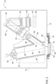
- the figure 1 shows a perspective view of a sensor arrangement 10. It comprises an approximately cuboid housing 12, which can be provided with lateral cooling fins (not shown), and a front panel 14, to which a flange 16 is attached.
- the flange 16 surrounds an opening in the housing 12.
- the flange 16 holds a window 18 that is sufficiently permeable for electromagnetic waves in the wavelength range to be examined DE 10 2020 205 708 A1 described manner) mounted, circular, flat disk and serves as a passage for electromagnetic waves, from a light source 40 to a sample 38 arranged outside of the housing 12 and for the light waves reflected from the sample 38 into the housing 12. There they are analyzed in order to determine certain properties of the sample.
- the sensor arrangement 12 can, as in FIG figure 2 shown, may be implemented as a near-infrared spectrometer, or any other optical sensor, eg a camera, a thermometer or a Raman spectrometer.
- the figure 2 shows a section through the sensor arrangement 10 of FIG figure 1 who care for harvesters and other agricultural machinery.
- the sensor arrangement 10 comprises the housing 12 provided with the window 18 on the front panel 14, in which an illumination source 40, a spectrometer arrangement 28 and optionally one or more standards (not shown) for internal recalibration are present.
- a processor 34 for acquiring and processing the measured values and an interface 36 to a bus system are also arranged in the housing 12 .
- Quartz or sapphire glass is preferably used for the window 18 in the housing 12, through which both the illumination radiation and the radiation reflected by the sample 38 pass. Sapphire glass enables the window 18 to have a sufficiently long service life, even with highly abrasive samples 38 (e.g. samples 38 containing sand).
- the lamp power of the light source 40 which preferably has a reflector 20, can be automatically regulated in order to adapt the spectrometer arrangement 28 to the various reflection behaviors of a wide variety of samples 38.
- the spectrometer arrangement 28 comprises a dispersion element 26 and a detector 32 with one or more sensitive elements and optionally has imaging optics assemblies 22, 30.
- the interface 36 in the housing 12 to a bus system is preferably a wireless or wired connection for data transmission and/or calibration and/or system diagnosis is carried out and standards such as CAN, USB, RS232, wireless LAN, etc. support. However, it is also possible to establish the connection from the sensor arrangement to the bus system via electrical and/or fiber-optic lines.
- the processor 34 for acquiring and processing the measured values is arranged in the housing 12 . From this processor 34 both raw data, i. H. the pre-processing of the data on a spectral basis, as well as calculated results are generated, which can then be transmitted to a bus system via the existing interface 36.
- the processor 34 also contains the software for the necessary bus management.
- the spectrometer arrangement 28 with the dispersing element 26 outside of the housing 12 .
- the reflected light in the housing 12 is detected by an optical arrangement and fed to the external spectrometer arrangement via glass fibers.
- the further elements such as the processor 34 etc. are also arranged externally.
- the optical arrangement that detects the reflected light would then be regarded as the detector 32 .
- the sensor arrangement 10 can be used on stationary systems or any machine in which the harvested crop or another sample flows past the measuring head, for example in combine harvesters or forage harvesters or liquid manure tanks, or the sensor arrangement 10 is moved past the harvested crop, for example in a windrow.
- the sample 38 to be measured is irradiated with light from the light source 40 .
- the light generated by the light source 40 the wavelength of which does not necessarily have to be only in the visible wavelength range, but can also be in the infrared or possibly in the ultraviolet, is concentrated by the reflector 20 and passed through a first (here tubular, i.e. circular-cylindrical) chamber 42, which extends from the light source 40 to a dust protection disk 44 adjacent to the window 18 at its lower end, to the window 18 .
- the radiation reflected by the sample 38 passes through the window 18 back into the first chamber 42 and from there into a second chamber 46 branching off from the first chamber 42 (here also tubular, ie circular-cylindrical).
- a second chamber 46 branching off from the first chamber 42 (here also tubular, ie circular-cylindrical).
- the chambers 42 , 46 are arranged within an inner housing 48 which is closed off from the window 18 by the dust protection disk 44 .
- the second chamber 46 does not have to open into the first chamber 42, but can be arranged separately from it (see Fig. WO 01/31304 A1 ).
- the quality of the signals provided by the detector (array) 32 is better the higher the ratio of useful signal to background.
- Part of the background is formed by scattered light which falls from the light source 40 into the spectrometer arrangement 28 after multiple reflections on the inner walls of the chambers 42 and 46 or on the inside of the flange 58 without interacting with the sample 38 .
- the dust protection pane 44 is coated on both sides in order to avoid unwanted reflections, which also applies analogously at least to the inside of the window 18 .
- the optical axis 50 of the light source 40 and the first chamber 42 are also arranged at an angle to the plane of the window 18 and the dust protection disk 44, which differs from the angle of the optical axis 52 of the spectrometer assembly 28 and the second chamber 46 to the plane of the window 18 differs.
- the inner walls of the first chamber 42 and the second chamber 46 are equipped with teeth 54,56. These prevent or at least reduce the probability that light generated by the light source 40 will reach the spectrometer arrangement 28 by reflection on the inner walls of the chambers 42, 46 by being reflected back in the direction of the light source 40 on the teeth 54 of the inner wall of the first chamber 42 becomes.
- the teeth 56 reflect any light that does not arrive on the optical axis 52 of the spectrometer arrangement 28 back in the direction of the window 18.
- the teeth 54 are therefore arranged in such a way that the surfaces of the teeth 54 facing the light source 40 are approximately radial to the optical axis 50 are directed, while the surfaces of the teeth 54 facing the window 18 extend obliquely inwards and axially.
- the toothings 56 are arranged such that the surfaces of the toothings 56 facing the window 18 are directed approximately radially to the optical axis 52, while the surfaces of the toothings 56 facing the spectrometer arrangement 28 run obliquely inwards and axially.
- the teeth 54, 56 can be blackened and/or matted in a manner known per se.
- the toothings 54, 65 ensure that incident light is always reflected in a direction that continues the path to the detector 32, so to speak. In addition, part of the light is absorbed by the teeth 54, 56. The scattered light therefore has to carry out significantly more reflections before it arrives at the detector 32 . Since light is lost with each reflection due to the frosting or the scattered light is thrown back, the overall intensity of the scattered light that arrives at the detector 32 decreases.
- toothing 58 is also provided there. There, too, the surfaces of the toothing 58 facing the light source 40 or the spectrometer arrangement 28 are aligned transversely to the plane of the window 18 and the surfaces following radially outwards are inclined outwards and downwards. This ensures that as little light as possible is reflected from the light source 40 directly into the spectrometer arrangement 28 on these surfaces.
- the window 18 is not arranged exactly in the center of the flange 16 .
- the teeth 58 of the flange 16 are therefore not concentric about the center of the window 18 but about a point 60 which is approximately where the optical axes 50, 52 intersect the window 18.
- the dimensioning and positioning of the toothings 54, 56, 58 can be carried out by means of a simulation calculation in that different dimensions and positions are tried out and the configuration leading to the lowest scattered light intensity in the spectrometer arrangement 28 is adopted.
- an agricultural working machine 240 is shown in the form of a liquid manure spreader, which is pulled over a field by a farm tractor 242 in order to apply liquid manure through a line 244 to a field.
- the output signal of the sensor arrangement 10, which interacts with the liquid manure flowing in the line 244, is supplied to a controller 248 which is also connected to a position determination system 246.
- the controller 248 controls a valve 250, which specifies the flow rate of the liquid manure through the line 244, based on an application map stored in advance in the controller 248, in which it is determined how much ingredient (e.g. nitrogen, potassium, etc.) is applied per unit area and based on the output signal in terms of compliance with the values specified in the application card.
- ingredient e.g. nitrogen, potassium, etc.
- FIG. 6 shows a further embodiment of a working machine 130 in the form of a self-propelled combine harvester 130, which is equipped with a sensor arrangement 10.
- the sensor assembly 10 is mounted on the wall of a cross auger 132 and interacts through an opening in the wall with the cleaned crop (grain) discharged from a cleaning device 134 and passed through the cross auger 132 to a grain elevator 136 which collects it in a grain tank 138 discards.
- the cleaning device 134 receives the crop from a crop receiving device 140 which feeds it to a threshing and separating unit 142 .
- the sensor arrangement 10 provides specific ingredient information such as protein content, starch content, oil content and moisture content of the harvested grain, which is stored on a map by a control unit 144 together with position information provided by a receiving antenna 148 of a satellite-based positioning system.
Landscapes
- Life Sciences & Earth Sciences (AREA)
- Environmental Sciences (AREA)
- Physics & Mathematics (AREA)
- Health & Medical Sciences (AREA)
- Chemical & Material Sciences (AREA)
- Analytical Chemistry (AREA)
- Biochemistry (AREA)
- General Health & Medical Sciences (AREA)
- General Physics & Mathematics (AREA)
- Immunology (AREA)
- Pathology (AREA)
- Investigating Or Analysing Materials By Optical Means (AREA)
Abstract
Description
- Die Erfindung betrifft eine Sensoranordnung mit einem Gehäuse mit einer Öffnung, in welcher ein für elektromagnetische Wellen transparentes Fenster montiert ist, einer im Gehäuse angeordneten Lichtquelle zur Erzeugung elektromagnetischer Wellen, und einem im Gehäuse angeordneten Detektor zum Nachweis durch das Fenster einlaufender, elektromagnetischer Wellen, die von der Lichtquelle durch das Fenster auf eine dem Fenster benachbarte Probe gefallen sind und von der Probe reflektiert wurden.
- Die Messung von Inhaltsstoffen mittels optischer Spektroskopie, insbesondere Nah-Infrarot-Spektroskopie, ist heute eine etablierte Technologie. Sie wird in vielen Anwendungen, beispielsweise in der Lebensmittelindustrie und in der Landwirtschaft genutzt, z.B. zur Untersuchung des Zustands auf einem Feld stehender Pflanzen, von Inhaltsstoffen geernteter Pflanzenteile oder der Zusammensetzung von Gülle (s. beispielsweise
WO 01/31304 A1 EP 3 437 451 A1 ), oder es werden Bilder des zu untersuchenden Materials mittels einer Kamera aufgenommen (EP 1 956 361 A2 ). - Derartige optische Sensoranordnungen werden angesichts der rauen
Umgebungsbedingungen, in denen sie eingesetzt werden, in Gehäusen eingebaut. Durch ein lichtdurchlässiges Fenster gelangen elektromagnetische Wellen, seien sie im sichtbaren Wellenlängenbereich oder kurz- oder langwelliger (Ultraviolett oder (Nah-) Infrarot), von der außerhalb des Gehäuses positionierten, zu untersuchenden Probe in das Innere des Gehäuses, um dort durch Detektionselemente der Sensoranordnung empfangen zu werden. Das Fenster schützt gleichzeitig das Innere der Sensoranordnung davor, dass die Probe in das Innere gelangt und Bestandteile der Sensoranordnung verunreinigt oder zerstört. Zudem dient das Fenster auch dazu, die Probe mittels einer im Inneren des Gehäuses angeordneten Quelle für elektromagnetische Wellen zu beleuchten. Die Sensoranordnungen umfassen demnach innerhalb des Gehäuses die Detektionselemente, die Lichtquelle und das Fenster als Schnittstelle zur Probe. Das Fenster wird bei manchen Sensoranordnungen (vgl.DE 10 2020 205 708 A1 ) an einem Flansch montiert, der vor einer Öffnung des Gehäuses positioniert und dort lösbar befestigt (verschraubt) wird. - Um Signale mit einem möglichst hohen Informationsgehalt von den Detektionselementen zu erhalten, ist es sinnvoll, Maßnahmen zu treffen, die es ermöglichen, dass die Detektionselemente möglichst wenig Streulicht (d.h. Licht, das keine der Messung zuträgliche Information trägt oder aus einer anderen als der für die Messung günstigen Richtung in die Detektionselemente gelangt) von der Lichtquelle oder anderen Orten erhalten. Im Stand der Technik wurde dazu vorgeschlagen, die Lichtquelle und die Detektionselemente in getrennten Gehäusen anzubringen, um getrennte Wege des Lichts von der Lichtquelle zum Fenster und vom Fenster zu den Detektionselementen bereitzustellen (
WO 01/31304 A1 EP 1 782 046 A1 ), oder dem Strahlengang des Lichts von der Probe zu einem Spektrometer benachbart angeordnete, gezahnte Streulichtfallen vorzusehen, die Licht der ersten Beugungsordnung (DE 10 2014 104 204 U1 ) oder von einer ungewünschten Signalquelle in das Gehäuse eines Spektrometers einfallendes Licht ausfiltern sollen (US 8 717 561 B2 ). - Die Anbringung von Lichtquelle und Detektionselementen in getrennten Gehäusen nach
WO 01/31304 A1 EP 1 782 046 A1 nur eine geringe Wirkung zeigt, solange nicht noch weitere Maßnahmen zur Reduzierung des Streulichts getroffen werden. DieDE 10 2014 104 204 U1 undUS 8 717 561 B2 beziehen sich auf Spektrometer, in deren Gehäuse keine Lichtquelle angeordnet ist, sondern im ersten Fall direkt von der Probe reflektiertes oder transmittiertes Licht und im zweiten Fall aus einer nicht der zu untersuchenden Signalquelle zuzuordnenden Richtung stammendes Licht ausgefiltert werden sollen, und somit Streulicht, das von der Lichtquelle in die Detektionselemente fallen sollte, nicht ausschalten können. - Die Erfindung hat sich zur Aufgabe gesetzt, die genannten Nachteile zu vermeiden oder zumindest zu vermindern.
- Diese Aufgabe wird erfindungsgemäß durch die Lehre des Patentanspruchs 1 gelöst, wobei in den weiteren Patentansprüchen Merkmale aufgeführt sind, die die Lösung in vorteilhafter Weise weiterentwickeln.
- Eine Sensoranordnung ist mit einem Gehäuse mit einer Öffnung, in welcher ein für elektromagnetische Wellen transparentes Fenster montiert ist, einer im Gehäuse angeordneten Lichtquelle zur Erzeugung elektromagnetischer Wellen, und einem im Gehäuse angeordneten Detektor zum Nachweis durch das Fenster einlaufender, elektromagnetischer Wellen, die von der Lichtquelle durch das Fenster auf eine dem Fenster benachbarte Probe gefallen sind und von der Probe reflektiert wurden ausgestattet.
- Innerhalb des Gehäuses ist eine Verzahnung angeordnet, die konfiguriert ist, von der Lichtquelle zum Detektor gelangendes Streulicht zu reduzieren. Auf diese Weise wird die Intensität des von der Lichtquelle zum Detektor gelangenden Streulichts, das nicht den Weg über die Probe zurückgelegt hat, vermindert, indem es an der Verzahnung absorbiert und/oder vom Detektor hinfort reflektiert wird.
- Die Verzahnung kann an der Wand einer zwischen der Lichtquelle und dem Fenster angeordneten, ersten Kammer und/oder an der Wand einer zwischen dem Fenster oder der ersten Kammer und dem Detektor angeordneten, zweiten Kammer angeordnet sein.
- Alternativ oder zusätzlich kann die Verzahnung an der Innenseite eines Flansches angebracht sein, der das Fenster am Gehäuse fixiert.
- Die Mittelachse des Fensters kann gegenüber der Mittelachse des Flanschs versetzt und die Verzahnung konzentrisch zu einem Punkt angeordnet sein, der zumindest näherungsweise auf der optischen Achse der Lichtquelle und des Detektors liegt.
- Die Verzahnung kann im Bereich zwischen der Lichtquelle und dem Fenster derart angeordnet sein, dass sie Streulicht in Richtung der Lichtquelle reflektiert. Die Verzahnung kann im Bereich zwischen dem Fenster und dem Detektor derart angeordnet sein, dass sie Streulicht in Richtung des Fensters reflektiert. Hierzu kann die Verzahnung eine Vielzahl an ringförmigen Zähnen umfassen, die jeweils eine quer zur optischen Achse der Lichtquelle oder des Detektors orientierte Fläche, welche der Lichtquelle bzw. dem Fenster zugewandt ist, und eine sich schräg nach außen erstreckende Fläche umfassen, die dem Fenster bzw. dem Detektor zugewandt ist.
- Der Detektor kann als Spektrometeranordnung, Kamera oder in beliebiger anderer Weise ausgeführt sein.
- In den Zeichnungen ist ein nachfolgend näher beschriebenes Ausführungsbeispiel der Erfindung dargestellt. Es zeigt:
- Fig. 1
- eine perspektivische Ansicht einer Sensoranordnung,
- Fig. 2
- einen Schnitt durch die Sensoranordnung der
Figur 1 , - Fig. 3
- eine perspektivische Ansicht eines Flansches mit darin eingebautem Fenster,
- Fig. 4
- eine seitliche Ansicht einer landwirtschaftlichen Arbeitsmaschine in Form eines Güllefasses mit einer Sensoranordnung nach
Figur 1 bis 3 , und - Fig. 5
- eine seitliche Ansicht einer landwirtschaftlichen Arbeitsmaschine in Form eines Mähdreschers mit einer Sensoranordnung nach
Figur 1 bis 3 . - Die
Figur 1 zeigt eine perspektivische Ansicht einer Sensoranordnung 10. Sie umfasst ein etwa quaderförmiges Gehäuse 12, das mit nicht gezeigten, seitlichen Kühlrippen versehen sein kann, und einer Frontplatte 14, an welcher ein Flansch 16 angebracht ist. Der Flansch 16 umrundet eine Öffnung im Gehäuse 12. Der Flansch 16 haltert ein für elektromagnetische Wellen im zu untersuchenden Wellenlängenbereich hinreichend durchlässiges Fenster 18. Das Fenster 18 ist durch eine am Flansch 16 (z.B. in der inDE 10 2020 205 708 A1 beschriebenen Weise) befestigte, kreisförmige, in sich flache Scheibe ausgeführt und dient als Durchlass für elektromagnetische Wellen, von einer Lichtquelle 40 zu einer außerhalb des Gehäuses 12 angeordneten Probe 38 und für die von der Probe 38 reflektierten Lichtwellen in das Gehäuse 12 hinein. Dort werden sie analysiert, um bestimmte Eigenschaften der Probe zu ermitteln. Die Sensoranordnung 12 kann, wie in derFigur 2 gezeigt, als Nahinfrarotspektrometer ausgeführt sein, oder ein beliebiger, anderer optischer Sensor sein, z.B. eine Kamera, ein Thermometer oder ein Raman-Spektrometer. - Die
Figur 2 zeigt einen Schnitt durch die Sensoranordnung 10 derFigur 1 , die sich für Erntemaschinen und andere landwirtschaftlich genutzte Maschinen eignet. Die Sensoranordnung 10 umfasst das an der Frontplatte 14 mit dem Fenster 18 versehenen Gehäuse 12, in dem eine Beleuchtungsquelle 40, eine Spektrometeranordnung 28 und ggf. ein oder mehrere nicht gezeigte Standards zur internen Rekalibrierung vorhanden sind. Im Gehäuse 12 sind zusätzlich ein Prozessor 34 zur Erfassung und Bearbeitung der Messwerte und eine Schnittstelle 36 zu einem Bussystem angeordnet. Für das Fenster 18 im Gehäuse 12, durch das sowohl die Beleuchtungsstrahlung als auch die von der Probe 38 reflektierte Strahlung fällt, wird vorzugsweise Quarz- oder Saphirglas verwendet. Saphirglas ermöglicht eine ausreichend hohe Standzeit des Fensters 18, auch bei hoch abrasiven Proben 38 (z. B. sandhaltige Proben 38). Die Lampenleistung der vorzugsweise über einen Reflektor 20 verfügenden Lichtquelle 40 kann automatisch regelbar sein, um die Spektrometeranordnung 28 an die verschiedenen Reflexionsverhalten unterschiedlichster Proben 38 anzupassen. - Die Spektrometeranordnung 28 umfasst ein Dispersionselement 26 und einen Detektor 32 mit einem oder mehreren sensitiven Elementen und verfügt gegebenenfalls über abbildende Optikbaugruppen 22, 30. Die im Gehäuse 12 vorhandene Schnittstelle 36 zu einem Bussystem ist vorzugsweise als drahtlose oder drahtgebundene Verbindung zur Datenübertragung und/oder Kalibrierung und/oder Systemdiagnose ausgeführt ist und kann Standards, wie CAN, USB, RS232, Wireless LAN u. a. unterstützen. Es ist aber auch möglich, die Verbindung von der Sensoranordnung zum Bussystem über elektrische und/oder faseroptische Leitungen herzustellen. Zusätzlich ist im Gehäuse 12 der Prozessor 34 zur Erfassung und Bearbeitung der Messwerte angeordnet. Von diesem Prozessor 34 können sowohl Rohdaten, d. h. die Vorverarbeitung der Daten auf spektraler Basis, als auch berechnete Ergebnisse erzeugt werden, die dann über die vorhandene Schnittstelle 36 zu einem Bussystem übertragen werden kann. Außerdem enthält der Prozessor 34 die Software für das notwendige Busmanagement.
- Es ist wäre auch denkbar, die Spektrometeranordnung 28 mit dem Dispersionselement 26 außerhalb des Gehäuses 12 zu positionieren. In diesem Fall wird das reflektierte Licht im Gehäuse 12 von einer optischen Anordnung erfasst und der externen Spektrometeranordnung über Glasfasern zugeführt. Dann sind die weiteren Elemente wie der Prozessor 34 etc. auch extern angeordnet. Als Detektor 32 wäre dann die optische Anordnung, die das reflektierte Licht erfasst, anzusehen.
- Anhand der Intensitätsverteilung der reflektierten Strahlung können basierend auf Kalibrierungen unterschiedliche Inhaltsstoffe, wie beispielsweise Feuchte, Protein, Stärke, Ölgehalt und Eigenschaften wie Schnittlänge, Faserzustand, Temperatur der Probe bestimmt werden. Mit der Sensoranordnung 10 sind sowohl statische Messungen als auch Messungen eines Materialstroms möglich. Die Sensoranordnung 10 kann an stationären Anlagen oder beliebigen Maschinen verwendet werden, bei denen das Erntegut oder eine andere Probe am Messkopf vorbeiströmt, beispielsweise in Mähdreschern oder Feldhäckslern oder Güllefässern, oder die Sensoranordnung 10 am Erntegut vorbeibewegt wird, beispielsweise an einem Schwad.
- Bei der Sensoranordnung 10 wird die zu messende Probe 38 mit Licht von der Lichtquelle 40 bestrahlt. Das von der Lichtquelle 40 erzeugte Licht, dessen Wellenlänge nicht notwendigerweise nur im sichtbaren Wellenlängenbereich liegen muss, sondern auch im Infraroten oder ggf. im Ultravioletten liegen kann, wird vom Reflektor 20 konzentriert und durch eine erste (hier rohrförmige, d.h. kreiszylindrische) Kammer 42, die sich von der Lichtquelle 40 bis zu einer dem Fenster 18 benachbarten Staubschutzscheibe 44 an seinem unteren Ende erstreckt, zum Fenster 18 geleitet. Die von der Probe 38 reflektierte Strahlung gelangt durch das Fenster 18 wieder in die erste Kammer 42 und von dort in eine von ersten Kammer 42 abzweigenden, zweite (hier ebenfalls rohrförmige, d.h. kreiszylindrische) Kammer 46. Am oberen Ende der zweiten Kammer 46 ist die Spektrometeranordnung 28 angeordnet. Die Kammern 42,46 sind innerhalb eines inneren Gehäuses 48 angeordnet, das zum Fenster 18 hin durch die Staubschutzscheibe 44 verschlossen ist. Es sei noch angemerkt, dass die zweite Kammer 46 nicht in die erste Kammer 42 münden muss, sondern getrennt davon angeordnet sein kann (s.
WO 01/31304 A1 - Es ist erkennbar, dass die Qualität der vom Detektor(array) 32 bereitgestellten Signale umso besser ist, je höher das Verhältnis aus Nutzsignal und Untergrund ist. Ein Teil des Untergrunds wird durch Streulicht gebildet, das von der Lichtquelle 40 nach Mehrfachreflektionen an den inneren Wänden der Kammern 42 und 46 oder an der Innenseite des Flansches 58 ohne Wechselwirkung mit der Probe 38 in die Spektrometeranordnung 28 fällt.
- Es werden daher vorliegend eine Reihe an Maßnahmen zur Verbesserung des Verhältnisses und Nutzsignal durch Verminderung des Streulichts getroffen. Die Staubschutzscheibe 44 ist beidseits vergütet, um unerwünschte Reflexionen zu vermeiden, was analog auch zumindest für die Innenseite des Fensters 18 gilt. Aus demselben Grunde sind auch die optische Achse 50 der Lichtquelle 40 und der ersten Kammer 42 in einem Winkel zur Ebene des Fensters 18 und der Staubschutzscheibe 44 angeordnet, der sich vom Winkel der optischen Achse 52 der Spektrometeranordnung 28 und der zweiten Kammer 46 gegenüber der Ebene des Fensters 18 unterscheidet.
- Weiterhin sind die Innenwände der ersten Kammer 42 und der zweiten Kammer 46 mit Verzahnungen 54, 56 ausgestattet. Diese verhindern oder verringern zumindest die Wahrscheinlichkeit, dass von der Lichtquelle 40 erzeugtes Licht durch Reflexion an den Innenwänden der Kammern 42, 46 in die Spektrometeranordnung 28 gelangt, indem es an den Verzahnungen 54 der Innenwand der ersten Kammer 42 wieder in Richtung der Lichtquelle 40 reflektiert wird. Analog reflektieren die Verzahnungen 56 jegliches Licht, das nicht auf der optischen Achse 52 der Spektrometeranordnung 28 einläuft, wieder in Richtung des Fensters 18. Die Verzahnungen 54 sind daher so angeordnet, dass die der Lichtquelle 40 zugewandten Flächen der Verzahnungen 54 etwa radial zur optischen Achse 50 gerichtet sind, während die dem Fenster 18 zugewandten Flächen der Verzahnungen 54 schräg nach innen und axial verlaufen. Analog sind die Verzahnungen 56 so angeordnet, dass die dem Fenster 18 zugewandten Flächen der Verzahnungen 56 etwa radial zur optischen Achse 52 gerichtet sind, während die der Spektrometeranordnung 28 zugewandten Flächen der Verzahnungen 56 schräg nach innen und axial verlaufen. Die Verzahnungen 54, 56 können in an sich bekannter Weise geschwärzt und/oder mattiert sein.
- Mit anderen Worten sorgen die Verzahnungen 54, 65 dafür, dass auftreffendes Licht stets in eine Richtung reflektiert wird, die den Weg zum Detektor 32 sozusagen weiter macht. Zudem wird ein Teil des Lichts an der Verzahnung 54, 56 absorbiert. Daher muss das Streulicht deutlich mehr Reflexionen durchführen, bis es beim Detektor 32 ankommt. Da bei jeder Reflexion aufgrund der Mattierung Licht verloren geht oder das Streulicht wieder zur zurückgeworfen wird, sinkt insgesamt die Intensität des Streulichts, das beim Detektor 32 ankommt.
- Eine weitere Quelle möglicher störender Reflexionen ist die Innenseite des Flansches 16. Da das Fenster 18 einen kleineren Durchmesser als der Flansch 16 aufweist, werden von der Lichtquelle 40 nicht nur das eigentliche Fenster 18, sondern auch die dem Fenster 18 benachbarten Flächen des Flansches 16 beleuchtet. Um von dort ausgehende Reflexionen in die Spektrometeranordnung 28 zu verhindern oder zumindest zu vermindern, ist auch dort eine Verzahnung 58 vorgesehen. Auch dort sind die der Lichtquelle 40 bzw. der Spektrometeranordnung 28 zugewandten Flächen der Verzahnung 58 quer zur Ebene des Fensters 18 ausgerichtet und die radial nach außen folgenden Flächen nach außen und unten hin geneigt. Dadurch erreicht man, dass an diesen Flächen möglichst wenig Licht von der Lichtquelle 40 direkt in die Spektrometeranordnung 28 reflektiert wird.
- Wie anhand der
Figur 3 erkennbar, ist das Fenster 18 nicht genau mittig im Flansch 16 angeordnet. Die Verzahnung 58 des Flansches 16 ist daher nicht konzentrisch um die Mitte des Fensters 18, sondern um einen Punkt 60 herum, der etwa dort liegt, wo die optischen Achsen 50, 52 das Fenster 18 schneiden. - Es sei noch angemerkt, dass die Dimensionierung und Positionierung der Verzahnungen 54, 56, 58 durch eine Simulationsrechnung erfolgen kann, indem unterschiedliche Abmessungen und Positionen durchprobiert und die zur geringsten Streulichtintensität in der Spektrometeranordnung 28 führende Konfiguration übernommen wird.
- In der
Figur 5 ist eine landwirtschaftliche Arbeitsmaschine 240 in Form eines Güllefasses dargestellt, das durch einen Ackerschlepper 242 über ein Feld gezogen wird, um Gülle durch eine Leitung 244 auf ein Feld auszubringen. Das Ausgangssignal der Sensoranordnung 10, die mit der in der Leitung 244 fließenden Gülle zusammenwirkt, wird einer Steuerung 248 zugeführt, die zudem mit einem Positionsbestimmungssystem 246 verbunden ist. Die Steuerung 248 kontrolliert ein Ventil 250, das die Flussrate der Gülle durch die Leitung 244 vorgibt, basierend auf einer in der Steuerung 248 im vorab abgespeicherten Ausbringkarte, in welcher festgelegt wird, wieviel Inhaltstoff (z.B. Stickstoff, Kalium etc.) je Flächeneinheit ausgebracht werden soll, und anhand des Ausgangssignals im Sinne einer Einhaltung der in der Ausbringkarte festgelegten Werte. - Die Figur 6 zeigt eine weitere Ausführungsform einer Arbeitsmaschine 130 in Form eines selbstfahrenden Mähdreschers 130, die mit einer Sensoranordnung 10 ausgestattet ist. Die Sensoranordnung 10 ist an der Wand einer Querförderschnecke 132 angebracht und wirkt durch eine Öffnung in der Wand mit dem gereinigten Erntegut (Körnern) zusammen, das von einer Reinigungseinrichtung 134 abgegeben und durch die Querförderschnecke 132 einem Körnerelevator 136 übergeben wird, der es in einem Korntank 138 ablegt. Die Reinigungseinrichtung 134 erhält das Erntegut von einer Erntegutaufnahmeeinrichtung 140, die es einer Dresch- und Trenneinheit 142 zuführt. Die Sensoranordnung 10 liefert bestimmte Inhaltsstoffangaben wie Proteingehalt, Stärkegehalt, Ölgehalt und Feuchtigkeitsanteil des geernteten Korns, die durch eine Kontrolleinheit 144 gemeinsam mit einer Positionsinformation, die von einer Empfangsantenne 148 eines satellitenbasierten Positionsbestimmungssystems bereitgestellt wird, in einer Karte abgespeichert werden.
Claims (8)
- Sensoranordnung (10), mit einem Gehäuse (12) mit einer Öffnung, in welcher ein für elektromagnetische Wellen transparentes Fenster (18) montiert ist, einer im Gehäuse (12) angeordneten Lichtquelle (40) zur Erzeugung elektromagnetischer Wellen, und einem im Gehäuse (12) angeordneten Detektor (32) zum Nachweis durch das Fenster (18) einlaufender, elektromagnetischer Wellen, die von der Lichtquelle durch das Fenster auf eine dem Fenster (18) benachbarte Probe gefallen sind und von der Probe reflektiert wurden, gekennzeichnet durch wenigstens eine innerhalb des Gehäuses (12) angeordnete, Verzahnung (54, 56, 58), die konfiguriert ist, von der Lichtquelle (40) zum Detektor (32) gelangendes Streulicht zu reduzieren.
- Sensoranordnung (10) nach Anspruch 1, wobei die Verzahnung (54, 56) an der Wand einer zwischen der Lichtquelle (40) und dem Fenster (18) angeordneten, ersten Kammer (42) und/oder an der Wand einer zwischen dem Fenster (18) oder der ersten Kammer (42) und dem Detektor (32) angeordneten, zweiten Kammer (46) angeordnet ist.
- Sensoranordnung nach Anspruch 1 oder 2, wobei die Verzahnung (58) an der Innenseite eines Flansches (16) angebracht ist, der das Fenster (18) am Gehäuse (12) fixiert.
- Sensoranordnung (10) nach Anspruch 3, wobei die Mittelachse des Fensters (18) gegenüber der Mittelachse des Flanschs (16) versetzt und die Verzahnung (58) konzentrisch zu einem Punkt (60) angeordnet ist, der zumindest näherungsweise auf der optischen Achse (50, 52) der Lichtquelle (40) und des Detektors (32) liegt.
- Sensoranordnung (10) nach einem der Ansprüche 1 bis 4, wobei die Verzahnung (54, 58) zwischen der Lichtquelle (40) und dem Fenster (18) derart angeordnet ist, dass sie Streulicht in Richtung der Lichtquelle (40) reflektiert und/oder die Verzahnung (56) zwischen dem Fenster (18) und dem Detektor (32) derart angeordnet ist, dass sie Streulicht in Richtung des Fensters (18) reflektiert.
- Sensoranordnung (10) nach Anspruch 5, wobei die Verzahnung (54, 56, 58) eine Vielzahl an ringförmigen Zähnen mit quer zur optischen Achse (50, 52) der Lichtquelle (40) oder des Detektors (329 orientierte Flächen, welche der Lichtquelle (40) bzw. dem Fenster (18) zugewandt sind, und sich schräg nach außen erstreckenden Flächen umfasst, die dem Fenster (18) bzw. dem Detektor (32) zugewandt sind.
- Sensoranordnung (10) nach einem der Ansprüche 1 bis 6, wobei der Detektor (32) eine Spektrometeranordnung (28) und/oder eine Kamera umfasst.
- Landwirtschaftliche Arbeitsmaschine (130, 240) mit einer Sensoranordnung (10) nach einem der vorhergehenden Ansprüche.
Applications Claiming Priority (1)
| Application Number | Priority Date | Filing Date | Title |
|---|---|---|---|
| DE102021130228.5A DE102021130228A1 (de) | 2021-11-18 | 2021-11-18 | Sensoranordnung |
Publications (2)
| Publication Number | Publication Date |
|---|---|
| EP4184148A1 true EP4184148A1 (de) | 2023-05-24 |
| EP4184148B1 EP4184148B1 (de) | 2025-07-09 |
Family
ID=83692922
Family Applications (1)
| Application Number | Title | Priority Date | Filing Date |
|---|---|---|---|
| EP22201585.1A Active EP4184148B1 (de) | 2021-11-18 | 2022-10-14 | Sensoranordnung |
Country Status (2)
| Country | Link |
|---|---|
| EP (1) | EP4184148B1 (de) |
| DE (1) | DE102021130228A1 (de) |
Cited By (1)
| Publication number | Priority date | Publication date | Assignee | Title |
|---|---|---|---|---|
| DE102023126147A1 (de) | 2023-09-26 | 2025-03-27 | Deere & Company | Sensorzusammenbau, landwirtschaftliche Maschine und zugehöriges Verfahren |
Citations (8)
| Publication number | Priority date | Publication date | Assignee | Title |
|---|---|---|---|---|
| EP0174186A2 (de) * | 1984-09-04 | 1986-03-12 | EASTMAN KODAK COMPANY (a New Jersey corporation) | Reflektometer |
| EP0952440A2 (de) * | 1998-04-20 | 1999-10-27 | Bayer Corporation | Photometrischer Messkopf mit Strahlformungsplatte |
| WO2001031304A1 (en) | 1999-10-25 | 2001-05-03 | Textron Systems Corporation | Integrated optics probe for spectral analysis |
| EP1782046A1 (de) | 2004-07-28 | 2007-05-09 | CNH Belgium N.V. | Vorrichtung und verfahren zur analyse der erntezusammensetzung in einer erntefördermaschine |
| EP1956361A2 (de) | 2007-02-07 | 2008-08-13 | Deere & Company | Messeinrichtung zur optischen und spektroskopischen Untersuchung einer Probe |
| US8717561B2 (en) | 2010-04-19 | 2014-05-06 | Oto Photonics, Inc. | Miniature spectrometer with stray light filtering structure |
| EP3437451A1 (de) | 2017-08-02 | 2019-02-06 | Deere & Company | Spektrometeranordnung |
| DE102020205708A1 (de) | 2020-05-06 | 2021-11-11 | Deere & Company | Sensoranordnung |
-
2021
- 2021-11-18 DE DE102021130228.5A patent/DE102021130228A1/de active Pending
-
2022
- 2022-10-14 EP EP22201585.1A patent/EP4184148B1/de active Active
Patent Citations (8)
| Publication number | Priority date | Publication date | Assignee | Title |
|---|---|---|---|---|
| EP0174186A2 (de) * | 1984-09-04 | 1986-03-12 | EASTMAN KODAK COMPANY (a New Jersey corporation) | Reflektometer |
| EP0952440A2 (de) * | 1998-04-20 | 1999-10-27 | Bayer Corporation | Photometrischer Messkopf mit Strahlformungsplatte |
| WO2001031304A1 (en) | 1999-10-25 | 2001-05-03 | Textron Systems Corporation | Integrated optics probe for spectral analysis |
| EP1782046A1 (de) | 2004-07-28 | 2007-05-09 | CNH Belgium N.V. | Vorrichtung und verfahren zur analyse der erntezusammensetzung in einer erntefördermaschine |
| EP1956361A2 (de) | 2007-02-07 | 2008-08-13 | Deere & Company | Messeinrichtung zur optischen und spektroskopischen Untersuchung einer Probe |
| US8717561B2 (en) | 2010-04-19 | 2014-05-06 | Oto Photonics, Inc. | Miniature spectrometer with stray light filtering structure |
| EP3437451A1 (de) | 2017-08-02 | 2019-02-06 | Deere & Company | Spektrometeranordnung |
| DE102020205708A1 (de) | 2020-05-06 | 2021-11-11 | Deere & Company | Sensoranordnung |
Cited By (2)
| Publication number | Priority date | Publication date | Assignee | Title |
|---|---|---|---|---|
| DE102023126147A1 (de) | 2023-09-26 | 2025-03-27 | Deere & Company | Sensorzusammenbau, landwirtschaftliche Maschine und zugehöriges Verfahren |
| EP4530608A1 (de) | 2023-09-26 | 2025-04-02 | Deere & Company | Sensorzusammenbau, landwirtschaftliche maschine und zugehöriges verfahren |
Also Published As
| Publication number | Publication date |
|---|---|
| EP4184148B1 (de) | 2025-07-09 |
| DE102021130228A1 (de) | 2023-05-25 |
Similar Documents
| Publication | Publication Date | Title |
|---|---|---|
| EP3444577B1 (de) | Spektrometrischer messkopf für forst-, land- und lebensmittelwirtschaftliche anwendungen | |
| EP1740928B1 (de) | Verfahren zur rekalibrierung eines spektrometrischen messkopfes | |
| EP1956361B1 (de) | Messeinrichtung zur optischen und spektroskopischen Untersuchung einer Probe | |
| DE69826896T2 (de) | Einrichtung zur überwachung der kornqualität | |
| EP2836818B1 (de) | Gasdetektorsystem | |
| EP0800074B1 (de) | Vorrichtung und Verwendung einer Vorrichtung zur Bestimmung der Konzentration von Hämoglobinderivaten in einer unverdünnten, unhämolysierten Vollblutprobe | |
| EP3437451B1 (de) | Landwirtschaftliche maschine mit einer spektrometeranordnung | |
| DE3713149A1 (de) | Fernmess-spektrophotometer | |
| EP1797414A1 (de) | Spektrometrischer messkopf für erntemaschinen und andere landwirtschaftlich genutzte maschinen | |
| EP1892520A1 (de) | Messvorrichtung zur Inhaltsstofferfassung | |
| DE69806516T2 (de) | Nahinfrarot spektrometer zum gebrauch in kombination mit einem mähdrescher für echtzeitkornanalyse | |
| EP2533031A1 (de) | Vorrichtung zur referenzierten Messung von reflektiertem Licht und Verfahren zum Kalibrieren einer solchen Vorrichtung | |
| EP3629006B1 (de) | Anordnung zur sensorischen untersuchung einer fliessfähigen probe | |
| EP4184148B1 (de) | Sensoranordnung | |
| DE102020205708A1 (de) | Sensoranordnung | |
| WO2014023810A1 (de) | Passives messsystem | |
| EP3704473B1 (de) | Neuartiger sensor für die ramanspektroskopie | |
| EP4296636A1 (de) | Verfahren zur vorkalibrierung und zur korrektur von messfehlern einer spektroskopischen messvorrichtung sowie messvorrichtung | |
| EP3961165A2 (de) | Landwirtschaftliche arbeitsmaschine | |
| DE102022116884A1 (de) | Optische Messvorrichtung zur spektralen Analyse einer Probe | |
| DE102023000154B3 (de) | Vorrichtung für das Recycling diffuser elektromagnetischer Strahlung | |
| EP3575776A1 (de) | Messsystem für kleinvolumige schüttgüter | |
| WO2025045877A1 (de) | Landwirtschaftliche erntemaschine und verfahren zur bestimmung mindestens einer eigenschaft von erntegut | |
| WO2024132739A1 (de) | Spektrometer zur spektralen analyse einer probe | |
| DE102021111827A1 (de) | Sensoranordnung zur Erfassung von Inhaltsstoffen |
Legal Events
| Date | Code | Title | Description |
|---|---|---|---|
| PUAI | Public reference made under article 153(3) epc to a published international application that has entered the european phase |
Free format text: ORIGINAL CODE: 0009012 |
|
| STAA | Information on the status of an ep patent application or granted ep patent |
Free format text: STATUS: THE APPLICATION HAS BEEN PUBLISHED |
|
| AK | Designated contracting states |
Kind code of ref document: A1 Designated state(s): AL AT BE BG CH CY CZ DE DK EE ES FI FR GB GR HR HU IE IS IT LI LT LU LV MC ME MK MT NL NO PL PT RO RS SE SI SK SM TR |
|
| STAA | Information on the status of an ep patent application or granted ep patent |
Free format text: STATUS: REQUEST FOR EXAMINATION WAS MADE |
|
| 17P | Request for examination filed |
Effective date: 20231124 |
|
| RBV | Designated contracting states (corrected) |
Designated state(s): AL AT BE BG CH CY CZ DE DK EE ES FI FR GB GR HR HU IE IS IT LI LT LU LV MC ME MK MT NL NO PL PT RO RS SE SI SK SM TR |
|
| GRAP | Despatch of communication of intention to grant a patent |
Free format text: ORIGINAL CODE: EPIDOSNIGR1 |
|
| STAA | Information on the status of an ep patent application or granted ep patent |
Free format text: STATUS: GRANT OF PATENT IS INTENDED |
|
| RIC1 | Information provided on ipc code assigned before grant |
Ipc: A01C 23/00 20060101ALN20250131BHEP Ipc: G01N 21/84 20060101ALN20250131BHEP Ipc: G01N 21/359 20140101ALN20250131BHEP Ipc: G01N 21/3563 20140101ALN20250131BHEP Ipc: A01D 41/127 20060101ALI20250131BHEP Ipc: G01N 21/47 20060101AFI20250131BHEP |
|
| INTG | Intention to grant announced |
Effective date: 20250213 |
|
| GRAS | Grant fee paid |
Free format text: ORIGINAL CODE: EPIDOSNIGR3 |
|
| GRAA | (expected) grant |
Free format text: ORIGINAL CODE: 0009210 |
|
| STAA | Information on the status of an ep patent application or granted ep patent |
Free format text: STATUS: THE PATENT HAS BEEN GRANTED |
|
| AK | Designated contracting states |
Kind code of ref document: B1 Designated state(s): AL AT BE BG CH CY CZ DE DK EE ES FI FR GB GR HR HU IE IS IT LI LT LU LV MC ME MK MT NL NO PL PT RO RS SE SI SK SM TR |
|
| REG | Reference to a national code |
Ref country code: GB Ref legal event code: FG4D Free format text: NOT ENGLISH |
|
| REG | Reference to a national code |
Ref country code: CH Ref legal event code: EP |
|
| REG | Reference to a national code |
Ref country code: IE Ref legal event code: FG4D Free format text: LANGUAGE OF EP DOCUMENT: GERMAN |
|
| REG | Reference to a national code |
Ref country code: DE Ref legal event code: R096 Ref document number: 502022004576 Country of ref document: DE |
|
| REG | Reference to a national code |
Ref country code: NL Ref legal event code: MP Effective date: 20250709 |
|
| PG25 | Lapsed in a contracting state [announced via postgrant information from national office to epo] |
Ref country code: PT Free format text: LAPSE BECAUSE OF FAILURE TO SUBMIT A TRANSLATION OF THE DESCRIPTION OR TO PAY THE FEE WITHIN THE PRESCRIBED TIME-LIMIT Effective date: 20251110 |
|
| PG25 | Lapsed in a contracting state [announced via postgrant information from national office to epo] |
Ref country code: NL Free format text: LAPSE BECAUSE OF FAILURE TO SUBMIT A TRANSLATION OF THE DESCRIPTION OR TO PAY THE FEE WITHIN THE PRESCRIBED TIME-LIMIT Effective date: 20250709 |
|
| PG25 | Lapsed in a contracting state [announced via postgrant information from national office to epo] |
Ref country code: IS Free format text: LAPSE BECAUSE OF FAILURE TO SUBMIT A TRANSLATION OF THE DESCRIPTION OR TO PAY THE FEE WITHIN THE PRESCRIBED TIME-LIMIT Effective date: 20251109 |
|
| PGFP | Annual fee paid to national office [announced via postgrant information from national office to epo] |
Ref country code: DE Payment date: 20250919 Year of fee payment: 4 |
|
| PG25 | Lapsed in a contracting state [announced via postgrant information from national office to epo] |
Ref country code: NO Free format text: LAPSE BECAUSE OF FAILURE TO SUBMIT A TRANSLATION OF THE DESCRIPTION OR TO PAY THE FEE WITHIN THE PRESCRIBED TIME-LIMIT Effective date: 20251009 |
|
| REG | Reference to a national code |
Ref country code: LT Ref legal event code: MG9D |
|
| PGFP | Annual fee paid to national office [announced via postgrant information from national office to epo] |
Ref country code: AT Payment date: 20260113 Year of fee payment: 4 |
|
| PG25 | Lapsed in a contracting state [announced via postgrant information from national office to epo] |
Ref country code: FI Free format text: LAPSE BECAUSE OF FAILURE TO SUBMIT A TRANSLATION OF THE DESCRIPTION OR TO PAY THE FEE WITHIN THE PRESCRIBED TIME-LIMIT Effective date: 20250709 |
|
| PG25 | Lapsed in a contracting state [announced via postgrant information from national office to epo] |
Ref country code: HR Free format text: LAPSE BECAUSE OF FAILURE TO SUBMIT A TRANSLATION OF THE DESCRIPTION OR TO PAY THE FEE WITHIN THE PRESCRIBED TIME-LIMIT Effective date: 20250709 |
|
| PGFP | Annual fee paid to national office [announced via postgrant information from national office to epo] |
Ref country code: FR Payment date: 20251027 Year of fee payment: 4 |
|
| PG25 | Lapsed in a contracting state [announced via postgrant information from national office to epo] |
Ref country code: SE Free format text: LAPSE BECAUSE OF FAILURE TO SUBMIT A TRANSLATION OF THE DESCRIPTION OR TO PAY THE FEE WITHIN THE PRESCRIBED TIME-LIMIT Effective date: 20250709 |
|
| PG25 | Lapsed in a contracting state [announced via postgrant information from national office to epo] |
Ref country code: LV Free format text: LAPSE BECAUSE OF FAILURE TO SUBMIT A TRANSLATION OF THE DESCRIPTION OR TO PAY THE FEE WITHIN THE PRESCRIBED TIME-LIMIT Effective date: 20250709 |
|
| PG25 | Lapsed in a contracting state [announced via postgrant information from national office to epo] |
Ref country code: BG Free format text: LAPSE BECAUSE OF FAILURE TO SUBMIT A TRANSLATION OF THE DESCRIPTION OR TO PAY THE FEE WITHIN THE PRESCRIBED TIME-LIMIT Effective date: 20250709 Ref country code: PL Free format text: LAPSE BECAUSE OF FAILURE TO SUBMIT A TRANSLATION OF THE DESCRIPTION OR TO PAY THE FEE WITHIN THE PRESCRIBED TIME-LIMIT Effective date: 20250709 |
|
| PG25 | Lapsed in a contracting state [announced via postgrant information from national office to epo] |
Ref country code: RS Free format text: LAPSE BECAUSE OF FAILURE TO SUBMIT A TRANSLATION OF THE DESCRIPTION OR TO PAY THE FEE WITHIN THE PRESCRIBED TIME-LIMIT Effective date: 20251009 |
|
| PG25 | Lapsed in a contracting state [announced via postgrant information from national office to epo] |
Ref country code: ES Free format text: LAPSE BECAUSE OF FAILURE TO SUBMIT A TRANSLATION OF THE DESCRIPTION OR TO PAY THE FEE WITHIN THE PRESCRIBED TIME-LIMIT Effective date: 20250709 |
|
| PG25 | Lapsed in a contracting state [announced via postgrant information from national office to epo] |
Ref country code: RO Free format text: LAPSE BECAUSE OF FAILURE TO SUBMIT A TRANSLATION OF THE DESCRIPTION OR TO PAY THE FEE WITHIN THE PRESCRIBED TIME-LIMIT Effective date: 20250709 |
|
| PG25 | Lapsed in a contracting state [announced via postgrant information from national office to epo] |
Ref country code: SM Free format text: LAPSE BECAUSE OF FAILURE TO SUBMIT A TRANSLATION OF THE DESCRIPTION OR TO PAY THE FEE WITHIN THE PRESCRIBED TIME-LIMIT Effective date: 20250709 |
|
| PG25 | Lapsed in a contracting state [announced via postgrant information from national office to epo] |
Ref country code: DK Free format text: LAPSE BECAUSE OF FAILURE TO SUBMIT A TRANSLATION OF THE DESCRIPTION OR TO PAY THE FEE WITHIN THE PRESCRIBED TIME-LIMIT Effective date: 20250709 |
|
| PG25 | Lapsed in a contracting state [announced via postgrant information from national office to epo] |
Ref country code: IT Free format text: LAPSE BECAUSE OF FAILURE TO SUBMIT A TRANSLATION OF THE DESCRIPTION OR TO PAY THE FEE WITHIN THE PRESCRIBED TIME-LIMIT Effective date: 20250709 |
|
| PG25 | Lapsed in a contracting state [announced via postgrant information from national office to epo] |
Ref country code: CZ Free format text: LAPSE BECAUSE OF FAILURE TO SUBMIT A TRANSLATION OF THE DESCRIPTION OR TO PAY THE FEE WITHIN THE PRESCRIBED TIME-LIMIT Effective date: 20250709 |
|
| PG25 | Lapsed in a contracting state [announced via postgrant information from national office to epo] |
Ref country code: EE Free format text: LAPSE BECAUSE OF FAILURE TO SUBMIT A TRANSLATION OF THE DESCRIPTION OR TO PAY THE FEE WITHIN THE PRESCRIBED TIME-LIMIT Effective date: 20250709 Ref country code: SK Free format text: LAPSE BECAUSE OF FAILURE TO SUBMIT A TRANSLATION OF THE DESCRIPTION OR TO PAY THE FEE WITHIN THE PRESCRIBED TIME-LIMIT Effective date: 20250709 |
|
| PLBE | No opposition filed within time limit |
Free format text: ORIGINAL CODE: 0009261 |
|
| STAA | Information on the status of an ep patent application or granted ep patent |
Free format text: STATUS: NO OPPOSITION FILED WITHIN TIME LIMIT |