EP4184142A1 - Optical turbine engine blade damage detector - Google Patents
Optical turbine engine blade damage detector Download PDFInfo
- Publication number
- EP4184142A1 EP4184142A1 EP22209226.4A EP22209226A EP4184142A1 EP 4184142 A1 EP4184142 A1 EP 4184142A1 EP 22209226 A EP22209226 A EP 22209226A EP 4184142 A1 EP4184142 A1 EP 4184142A1
- Authority
- EP
- European Patent Office
- Prior art keywords
- light
- blades
- controller
- amplitude
- returns
- Prior art date
- Legal status (The legal status is an assumption and is not a legal conclusion. Google has not performed a legal analysis and makes no representation as to the accuracy of the status listed.)
- Granted
Links
Images


Classifications
-
- G—PHYSICS
- G01—MEASURING; TESTING
- G01M—TESTING STATIC OR DYNAMIC BALANCE OF MACHINES OR STRUCTURES; TESTING OF STRUCTURES OR APPARATUS, NOT OTHERWISE PROVIDED FOR
- G01M5/00—Investigating the elasticity of structures, e.g. deflection of bridges or air-craft wings
- G01M5/0016—Investigating the elasticity of structures, e.g. deflection of bridges or air-craft wings of aircraft wings or blades
-
- G—PHYSICS
- G01—MEASURING; TESTING
- G01N—INVESTIGATING OR ANALYSING MATERIALS BY DETERMINING THEIR CHEMICAL OR PHYSICAL PROPERTIES
- G01N21/00—Investigating or analysing materials by the use of optical means, i.e. using sub-millimetre waves, infrared, visible or ultraviolet light
- G01N21/84—Systems specially adapted for particular applications
- G01N21/88—Investigating the presence of flaws or contamination
- G01N21/89—Investigating the presence of flaws or contamination in moving material, e.g. running paper or textiles
- G01N21/8914—Investigating the presence of flaws or contamination in moving material, e.g. running paper or textiles characterised by the material examined
-
- F—MECHANICAL ENGINEERING; LIGHTING; HEATING; WEAPONS; BLASTING
- F01—MACHINES OR ENGINES IN GENERAL; ENGINE PLANTS IN GENERAL; STEAM ENGINES
- F01D—NON-POSITIVE DISPLACEMENT MACHINES OR ENGINES, e.g. STEAM TURBINES
- F01D21/00—Shutting-down of machines or engines, e.g. in emergency; Regulating, controlling, or safety means not otherwise provided for
- F01D21/003—Arrangements for testing or measuring
-
- G—PHYSICS
- G01—MEASURING; TESTING
- G01M—TESTING STATIC OR DYNAMIC BALANCE OF MACHINES OR STRUCTURES; TESTING OF STRUCTURES OR APPARATUS, NOT OTHERWISE PROVIDED FOR
- G01M11/00—Testing of optical apparatus; Testing structures by optical methods not otherwise provided for
- G01M11/08—Testing mechanical properties
- G01M11/081—Testing mechanical properties by using a contact-less detection method, i.e. with a camera
-
- G—PHYSICS
- G01—MEASURING; TESTING
- G01M—TESTING STATIC OR DYNAMIC BALANCE OF MACHINES OR STRUCTURES; TESTING OF STRUCTURES OR APPARATUS, NOT OTHERWISE PROVIDED FOR
- G01M5/00—Investigating the elasticity of structures, e.g. deflection of bridges or air-craft wings
- G01M5/0033—Investigating the elasticity of structures, e.g. deflection of bridges or air-craft wings by determining damage, crack or wear
-
- G—PHYSICS
- G01—MEASURING; TESTING
- G01M—TESTING STATIC OR DYNAMIC BALANCE OF MACHINES OR STRUCTURES; TESTING OF STRUCTURES OR APPARATUS, NOT OTHERWISE PROVIDED FOR
- G01M5/00—Investigating the elasticity of structures, e.g. deflection of bridges or air-craft wings
- G01M5/0091—Investigating the elasticity of structures, e.g. deflection of bridges or air-craft wings by using electromagnetic excitation or detection
-
- G—PHYSICS
- G01—MEASURING; TESTING
- G01N—INVESTIGATING OR ANALYSING MATERIALS BY DETERMINING THEIR CHEMICAL OR PHYSICAL PROPERTIES
- G01N21/00—Investigating or analysing materials by the use of optical means, i.e. using sub-millimetre waves, infrared, visible or ultraviolet light
- G01N21/17—Systems in which incident light is modified in accordance with the properties of the material investigated
- G01N21/47—Scattering, i.e. diffuse reflection
- G01N21/4738—Diffuse reflection, e.g. also for testing fluids, fibrous materials
-
- F—MECHANICAL ENGINEERING; LIGHTING; HEATING; WEAPONS; BLASTING
- F05—INDEXING SCHEMES RELATING TO ENGINES OR PUMPS IN VARIOUS SUBCLASSES OF CLASSES F01-F04
- F05D—INDEXING SCHEME FOR ASPECTS RELATING TO NON-POSITIVE-DISPLACEMENT MACHINES OR ENGINES, GAS-TURBINES OR JET-PROPULSION PLANTS
- F05D2270/00—Control
- F05D2270/80—Devices generating input signals, e.g. transducers, sensors, cameras or strain gauges
- F05D2270/804—Optical devices
-
- G—PHYSICS
- G01—MEASURING; TESTING
- G01N—INVESTIGATING OR ANALYSING MATERIALS BY DETERMINING THEIR CHEMICAL OR PHYSICAL PROPERTIES
- G01N21/00—Investigating or analysing materials by the use of optical means, i.e. using sub-millimetre waves, infrared, visible or ultraviolet light
- G01N21/17—Systems in which incident light is modified in accordance with the properties of the material investigated
- G01N21/47—Scattering, i.e. diffuse reflection
- G01N2021/4704—Angular selective
- G01N2021/4707—Forward scatter; Low angle scatter
-
- G—PHYSICS
- G01—MEASURING; TESTING
- G01N—INVESTIGATING OR ANALYSING MATERIALS BY DETERMINING THEIR CHEMICAL OR PHYSICAL PROPERTIES
- G01N21/00—Investigating or analysing materials by the use of optical means, i.e. using sub-millimetre waves, infrared, visible or ultraviolet light
- G01N21/17—Systems in which incident light is modified in accordance with the properties of the material investigated
- G01N21/47—Scattering, i.e. diffuse reflection
- G01N2021/4704—Angular selective
- G01N2021/4709—Backscatter
Definitions
- the present disclosure relates to a turbomachine and, more particularly, to a damage detection system and algorithm configured to inspect a rotor of the turbomachine during operation.
- Aircraft engines are turbomachines that can be damaged by foreign object debris or FOD. Large objects, for example a large bird strike, can cause significant changes that can be detected by monitoring systems, such as shaft vibration. Smaller objects can cause damage that can be difficult to detect visually. Regular inspection is performed to determine if any such damage has occurred such that maintenance can be performed.
- a damage detection system in accordance with an exemplary embodiment of this disclosure, includes an emitter, a receiver, and a controller.
- the emitter has an orientation to emit a plurality of light pulses along an emission axis intersecting a plurality of blades of a turbomachine rotor.
- the receiver has a first field of view intersecting the emission axis to define a first interrogation volume through which the plurality of blades rotates during operation of the turbomachine.
- the controller includes a processor and computer-readable memory encoded with instructions that, when executed by the processor, cause the system to emit the plurality of light pulses from the emitter toward the plurality of blades as the blades rotate within the turbomachine.
- the system collects, at the receiver, a plurality of light returns scattered by the plurality of blades within the interrogation volume.
- the controller determines an amplitude change of the first light returns and outputs an indication of damages based on the amplitude change detected within the light returns.
- a damage control system for a turbomachine includes one or more emitters, one or more receivers, and a controller.
- rotor blades pass through an interrogation volume defined about an intersection of an emitter and receiver field of view.
- Emitters transmit visible and/or infrared light using a continuous beam or intermittent pulses, and receivers collect back scatter, forward scatter, and/or side scatter light returns.
- Light returns collected over a period of time define one or more light return amplitude profiles, which are analyzed for light amplitude changes.
- the controller compares light amplitude changes to one or more damage criteria and output an indication of blade damage when the light amplitude change satisfies the damage detection criteria.
- the damage detection system monitors a turbomachine rotor in situ and during operation of the turbomachine to identify blade damage that would otherwise be undetected by analyzing primary turbomachine parameters such as rotational speed, operational pressures and temperatures, and vibration.
- FIG. 1 is a schematic representation of damage detection system 10 installed onto turbomachine 12 to inspect rotor 14, which includes multiple blades 16 arranged circumferentially about rotational axis 18.
- Damage detection system 10 includes at least one emitter 20, at least one receiver 22, and controller 24.
- Emitter 20 and receiver 22 are mounted to turbomachine 12 within a field of view of rotor 14 and arranged such that emitter line of sight 26 (or emission axis) intersects receiver line of sight 28 to define interrogation volume 30 about the intersection.
- turbomachine 12 is a bypass gas turbine engine for an aircraft and rotor 14 is a fan rotor.
- rotor 14 is a fan rotor.
- the technique disclosed herein are applicable to other aircraft engine types, such as turboprop engines and turboshaft engines, as well as non-aircraft applications including industrial gas turbine engines and other turbomachinery.
- Receiver 22 can be co-located with emitter 20 or mounted near emitter 16 such that receiver 22 intercepts light scattered in a direction opposite an emission direction (i.e., back scatter). In other arrangements, receiver 22 can be spaced from emitter 20 such that receiver 22 intercepts light scattered in a direction along an emission direction (i.e., forward scatter). When receiver 22 is positioned at right angles to the emission direction, receiver 22 collects light returns scattered at or near right angles to the emission direction (i.e., side scatter). Between back scatter and side scatter locations and between side scatter and forward scatter receiver positions, different proportions of back scatter, forward scatter, and side scatter light returns can be collected by receiver 22. Typically, light returns forming an angle between 135 degrees and 180 degrees with the emission direction are considered to be backscatter. Light returns that form an angle between 45 and 135 degrees relative to the emission direction are classified as side scatter while returns parallel to the emission direction or forming an angle between 0 degrees and 45 degrees of the emission direction are considered forward scatter.
- receivers 22 may initially receive predominately back scatter, side scatter, or forward scatter light returns, the type of light returns collected by receiver 22 can change based on a change in surface features. For instance, wear of blades 16 or damage to blades 16 from foreign object debris (FOD) may cause a change to blade topography that produces a commensurate change in back scatter, forward scatter, and/or side scatter amplitude.
- FOD foreign object debris
- multiple emitters 20 and/or receivers 22 are used to inspect rotor 14 of turbomachine 12.
- a single emitter 20 can be associated with multiple receivers 22, each receiver 22 arranged to intercept light scattered by rotor 14 that originates from emitter 20.
- receivers 22A, 22B, and 22C are positioned to receive light returns from emitter 20.
- Receiver 22A is collocated with emitter 20 to receive primarily backscatter light returns.
- Receiver 22B is positioned along the emission direction to receive forward light scatter returns.
- Receiver 22C has an intermediate position between receiver 22A and receiver 22B to receive side scatter returns.
- each independent channel of a multi-channel receiver 22 (or line camera) can interrogate a different radial station of blades 16 in order to collect light returns from a single emitter 20 or multiple emitters 20.
- Each emitter 20 of detection system 10 can be, for example, a light emitting diode (LED) or a visible and/or infrared laser. Accordingly, light produced by emitters 20 can be incoherent or coherent.
- Receivers 22 are photoelectric sensors that detect light amplitude scattered by a target (e.g., blade 16) and output a signal representative of the collected light amplitude.
- receivers 22 can be avalanche photo-diodes (APD) and/or multi-channel photon counters (MPPC). Additionally, receivers 22 can be used in conjunction with emitters 20 to determine a time of flight of light collected at receivers 22. Further, emitters 20 can transmit light continuously or intermittently as light pulses.
- the light pulse frequency can be varied to increase or decrease inspection resolution as necessary for the particular application. For example, shorter light pulses illuminate a smaller area of blade 16 when blades 16 are rotating at speed, which can increase sensitivity for smaller surface features of blades 16. Further, shorter light pulses allow receivers 22 to attain higher sampling rates, if desired.
- the light pulse frequency can be at least a multiple of a product equal to a rotational speed of rotor 14 times a number of blades 16 assembled onto rotor 14 in order to ensure multiple observations of each blade 16. In other embodiments, the light pulse frequency of one or more emitters 20 can be less than the rotational speed of rotor 14 times a number of blades 16.
- controller 24 synchronizes the emitter light pulses to a rotational position of blades 16 based on a signal provided by a rotational position sensor or derived from a rotational speed sensor. Accordingly, each light pulse illuminates one or more target locations of blades 16, even though rotor 14 may complete multiple rotations between samples.
- emitters 20 and/or receivers 22 can be mounted directly to or flush with a surface of turbomachine 12. In other instances, one or more of emitters 20 and receivers 22 are mounted to turbomachine 12 remote from the surface, light pulses and light returns traversing between emitter 20 and/or receiver 22 via a fiber optic cable. Fiber optic cables can be bifurcated, containing two or more discrete fiber optic paths such that a single cable can be shared between an emitter and receiver, between multiple emitters, or between multiple receivers. Further, any of the foregoing examples can include lens 23 to focus and/or filter light transmitted by emitters 20 or to collect and filter light intercepted by receivers 22.
- Controller 24 includes one or more processors 32 and system memory 34 that stores damage detection routine for inspecting blades of a turbomachine rotor to determine the presence of blade damage due to wear and/or foreign object debris (FOD) damage.
- Processor 32 executes damage detection algorithm as described in further detail below. Examples of processor 32 can include any one or more of a microprocessor, a controller, a digital signal processor (DSP), an application specific integrated circuit (ASIC), a field-programmable gate array (FPGA), or other equivalent discrete or integrated logic circuitry.
- System memory 34 can be configured to store information within controller 24 during operation as well as any inspection criteria necessary for distinguishing damaged regions of blades 16. System memory 34, in some examples, is described as computer-readable storage media.
- a computer-readable storage medium can include a non-transitory medium.
- the term "non-transitory” can indicate that the storage medium is not embodied in a carrier wave or a propagated signal.
- a non-transitory storage medium can store data that can, over time, change (e.g., in RAM or cache).
- System memory 34 can include volatile and non-volatile computer-readable memories. Examples of volatile memories can include random access memories (RAM), dynamic random-access memories (DRAM), static random-access memories (SRAM), and other forms of volatile memories. Examples of non-volatile memories can include, e.g., magnetic hard discs, optical discs, flash memories, or forms of electrically programmable memories (EPROM) or electrically erasable and programmable (EEPROM) memories.
- processor 32 and system memory 34 are collocated in a control unit, which itself can be collocated with other components of damage detection system 10.
- any one or more components and/or described functionality of controller 24 can be distributed among multiple hardware units.
- controller 24 can be incorporated into an electric engine control (EEC) unit or a full-authority digital engine control (FADEC) to perform functions other than those required by damage detection system 10.
- controller 24 can be a module discrete from other aircraft or engine control modules, which may be collocated with or remote from other aircraft or engine control modules and/or other components of damage detection system 10.
- controller 24 can include any combination of devices and components that are electrically, communicatively, or otherwise operatively connected to perform functionality attributed herein to controller 24.
- controller 24 can include drive circuit 36, analog-to-digital converter (ADC) 38, and alarm 40.
- Drive circuit 36 is an electrical circuit constructed to regulate the voltage and/or current supplied to emitter 20.
- Drive circuit 36 can be designed to produce light from one or more emitter 20 at a target frequency. Additionally, the design of drive circuit 36 can facilitate continuous light emissions from emitters 20 or supply intermittent power to emitter 20 such that emitter produces light pulses 20 at the target frequency.
- receivers 22 produce an analog voltage and/or current in proportion to the amplitude of light collected
- an analog-to-digital (ADC) converter 38 can be used to convert these analogue signals into digital signals for use by the controller 24.
- controller 24 can include alarm 40 for outputting a signal indicative of blade damage to another system.
- detection systems 10 incorporated into aircraft can output an indication of blade damage to an electric engine controller (EEC), a full authority digital engine controller (FADEC), or another engine and/or aircraft system.
- EEC electric engine controller
- FADEC full authority digital engine controller
- alarm 40 can output an indication of blade damage to a display so that an operator can take corrective action.
- FIG. 3A depicts an exemplary emitter 20 that includes lens 23A for illuminating a line of light along blade 16.
- Lens 23A includes curved inlet surface 42 and flat outlet surface 44. In an emission direction from inlet surface 42 to outlet surface 44, lens 23A diverges such that a cross-sectional area of outlet surface 44 exceeds a cross-sectional area of inlet surface 42.
- Light entering inlet surface 42 refracts through lens 23A to produce a fanned light structure emitted from outlet surface 44. This fanned light structure illuminates a line along the surface of blade 16, which can be collected by one or more receivers 22.
- FIG. 3B depicts another exemplary embodiment of emitter 20 that includes mirror 23B.
- Mirror 23B rotates about axis 46 to thereby redirect light produced by emitter 20 to illuminate path P on a surface of blade 16.
- Receiver 22 collects light scatter from path P for each blade 16 passing through the inspection volume associated with emitter 20 and receiver 22.
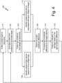
- FIG. 4 is a flow chart describing damage detection algorithm 100 stored within and executed by controller 24.
- Damage control algorithm 100 includes steps 102, 104, 106, 108, 110, 112, 114, and 116.
- the sequence depicted is for illustrative purposes only and is not meant to limit damage detection algorithm 100 in any way as it is understood that the portions of the algorithm can proceed in a different logical order, additional or intervening portions can be included, or described portions of the algorithm can be divided into multiple portions, or described portions of the algorithm can be omitted without detracting from the described above.
- controller 24 causes each emitter 20 of damage detection system 10 to emit light toward one or more blade 16 during operation of turbomachine 12. Emitted light can be produced continuously to illuminate interrogation volume 30. Alternatively, emitter 20 may produce light intermittently, emitting light pulses at a target frequency and pulse width (or light pulse duration). As discussed above, damage detection system 10 includes at least one emitter, and may include more than one emitter 20 arranged to illuminate the one or more interrogation volume through which blades 16 rotate during operation of turbomachine 12. Where multiple emitters 20 are utilized by damage detection system 10, damage detection algorithm 100 may cause each emitter 20 to produce light simultaneously such that receivers 22 collect light transmitted from each emitter 20.
- the proximity and/or configuration of emitters 20 and receivers 22 may benefit by transmitting light from each emitter 20 sequentially such that at any given instant in time, only one or a subset of emitters 20 produces light.
- Each emitter 20 can illuminate a single spot of blade 16.
- emitter 20 can include lens 23, distributing light emissions to thereby illuminate a line of blade 16 as shown in FIG. 3A .
- emitter 20 can scan along path P of blade 16 as shown in FIG. 3B .
- one or more receivers 22 collect light scattered from blade 16. Depending on the relative positions of emitters 20 and receivers 22, receivers 22 can collect predominately back scatter light returns, forward scatter light returns, or side scatter light returns.
- controller 24 Upon receiving light return amplitude data from each receiver 22, controller 24 stores light return amplitude data. Steps 102 and 104 repeat for a period of time enabling controller 24 to record light amplitude data as a function of time for each receiver 22 of damage detection system 10. From the light amplitude data, controller 24 determines a light amplitude difference in step 106 by comparing the light return amplitude at different time steps.
- Calculating the light amplitude change can be augmented by including one or more of the following steps.
- the orientation of emitter 20 relative to blades 16, and/or the number and spacing of blades 16 within turbomachine 12 may permit light emissions to pass between adjacent blades 16.
- time of flight data can be used to identify a subset of light returns associated with one or more blades 16.
- controller 24 determines a time of flight for each light pulse transmitted from emitter 20 and collected by receiver 22 in step 108 by comparing the time step when emitter 20 produces a light pulse and the time step when receiver 22 collects the emitted light pulse.
- controller 24 may exclude light returns having a time of flight greater than a threshold value, indicating a light pulse returning from behind the intended blade inspection region. In other instances, controller 24 can exclude light returns having a time of flight greater than an upper threshold and less than a lower threshold to exclude returns reflected from objects or features of turbomachine 12 in front of the intended target region.
- time-of-flight data within upper and lower thresholds can be further divided into subranges. Each subrange can be associated with a radial station of blades 16. Using any of the foregoing light return subsets, controller can determine a light amplitude change in step 106.
- controller 24 can identify a subset of light returns associated with each rotation of rotor 14 in step 110.
- controller 24 can identify a repeating pattern of light amplitude peaks and/or troughs in the light return amplitude signal.
- individual rotations can be identified by counting a predetermined number of peaks and/or troughs, each peak or trough associated with one of blades 16.
- light returns associated with each rotation can be identified by subdividing the light returns signals accordingly to a time interval calculated as a function of rotational speed.
- a first set of light returns are collected during multiple rotations of rotor 14 to establish a baseline light amplitude profile.
- controller 24 may determine a light amplitude difference by comparing light return amplitudes from different sequential or non-sequential rotations in step 106.
- the light return amplitude calculation can be improved by first measuring an ambient light level in step 112.
- one or more of receivers 22 collect light at a time preceding or between light emissions from emitters 20. Without first emitting a light pulse from emitter 20, the light amplitude determined from receivers 22 is representative of the ambient light level, which may change during operation of turbomachine 12.
- the light return amplitude data can be corrected or prior to determining a light amplitude difference in step 106. Accordingly, variances of the light amplitude data due to changes in ambient light amplitude can be reduced or eliminated.
- controller 24 compares each calculated light amplitude change to a damage criterion in step 114.
- the damage criterion can be a threshold amplitude change in one or more of back scatter light returns, forward scatter light returns, and side scatter light returns.
- the threshold amplitude change is selected to exceed a light amplitude variation due to signal noise.
- the light return profile may include predominately forward light scatter associated with spectral reflection of the blade surface accompanied by a relatively small amount of back scatter and/or side scatter.
- the damaged region may produce a diffused reflection of light pulses characterized by increased back scatter light returns and/or side scatter light returns accompanied by decreased forward scatter light returns. Contrastingly, the surface roughness of some coated blades 16 can produce predominately diffuse reflectance in an undamaged state. Damage to such blades 16 may expose uncoated material. In this instance, damage to this blade can be detected by deviations from the baseline light returns, in which the backscatter, side scatter, and forward scatter light returns may be used to characterize the type of damage.
- damage detection algorithm 100 utilizes step 110, light returns can be evaluated on a rotation-to-rotation basis. For instance, the average forward scatter, side scatter, and back scatter light return for a given rotation can be compared to one or more subsequent rotations. Average light scatter values deviating from a previous average value by more than a threshold may indicate damage to one or more blades 16. In other embodiments, peaks and or troughs of a given rotation can be used to associate subregions of the light return profile with individual blades. In this instance, changes in forward scatter, back scatter, and or side scatter returns associated may indicate damage to a particular blade 16 of rotor 14.
- controller 24 may output an indication of blade damage in step 116.
- controller 24 may output a signal to an electric engine controller (EEC), a full authority digital engine controller (FADEC), or another peripheral system representative of damage to one or more blades 16 and, in some instance, damage to a particular blade 16.
- EEC electric engine controller
- FADEC full authority digital engine controller
- a damage indication can be output to a display viewable by an operator.
- an indication of blade damage can be output to an avionics display in the cockpit of the aircraft.
- Steps 102, 104, 106, 114, 116 and if included, steps 108, 110, and 112 repeat at a predetermined sampling rate. Accordingly, damage detection algorithm 100 inspects blades 16 of rotor 14 in situ and, outputs an indication of damage in real time.
- a system for detecting damage of a plurality of blades rotatable within a turbomachine includes, among other possible things, an emitter, a first receiver, and a controller.
- the emitter is orientated to emit a plurality of light pulses along an emission axis intersecting the plurality of blades.
- the first receiver has a first field of view intersecting the emission axis to define a first interrogation volume through which the plurality of blades rotates during operation of the turbomachine.
- the controller includes a processor and computer-readable memory in communication with the emitter and receiver.
- the computer-readable memory is encoded with instructions that, when executed by the processor, cause the system to emit the plurality of light pulses from the emitter toward the plurality of blades as the blades rotate within the turbomachine.
- the system receives a plurality of first light returns at the first receiver that have been scattered by the plurality of blades within the first interrogation volume.
- the system determines a first amplitude change of the plurality of first light returns and outputs an indication of damage to the blades based on the firs amplitude change of the light returns.
- the system of the preceding paragraph can optionally include, additionally and/or alternatively, any one or more of the following features, configurations and/or additional components
- a further embodiment of the foregoing system wherein the first receiver can be collocated with the emitter to receive back scatter light returns.
- controller can output the indication of damage based on a change in back scatter light return amplitude that exceeds a threshold light amplitude change.
- controller can output the indication of damage based on an increase in back scatter light return amplitude.
- controller can output the indication of damage based on a decrease in back scatter light return amplitude.
- controller can output an indication of damage based on an increase in forward scatter light return amplitude.
- controller can output an indication of damage based on a decrease in forward scatter light return amplitude.
- controller can output the indication of damage based on a change in forward scatter light return amplitude that exceeds a threshold light amplitude change.
- controller can output the indication of damage based on an increase in side scatter light return amplitude.
- controller can output the indication of damage based on a decrease in side scatter light return amplitude.
- controller can output the indication of damage based on a change of side scatter light amplitude that exceeds a threshold light amplitude change.
- the computer-readable memory can be encoded with instructions that, when executed by the processor, cause the system to determine, by the controller, a first subset of light returns corresponding to a first rotation of the plurality of blades.
- the computer-readable memory can be encoded with instructions that, when executed by the processor, cause the system to determine, by the controller, a second subset of light returns corresponding to a second rotation of the plurality of blades.
- a further embodiment of any of the foregoing systems, wherein the indication of damage can be output by the controller based on a change in light return amplitude between the first rotation and the second rotation.
- a further embodiment of any of the foregoing systems can include a second receiver having a second field of view intersecting the emission axis to define a second interrogation volume through which the plurality of blades rotates during operation of the turbomachine.
- the computer-readable memory can be encoded with instructions that, when executed by the processor, cause the system to receive, at the second receiver, a plurality of second light returns scattered by the plurality of blades within the second interrogation volume.
- the computer-readable memory can be encoded with instructions that, when executed by the processor, cause the system to determine, by the controller, a second amplitude change of the second light returns.
- a further embodiment of any of the foregoing systems, wherein the first amplitude change can indicate increased light amplitude of the plurality of first light returns.
- the computer-readable memory can be encoded with instructions that, when executed by the processor, cause the system to determine a rotational speed of the plurality of blades based on the plurality of first light returns.
- computer-readable memory can be encoded with instructions that, when executed by the processor, cause the system to receive, at the first receiver, an ambient light level.
- the computer-readable memory can be encoded with instructions that, when executed by the processor, cause the system to determine, by the controller, at least one of a first amplitude change of the first light returns based on an amplitude of first light returns and the ambident light level.
- the first emitter can include a lens.
- the lens can include a rounded inlet surface that diverges outward along the emission axis and terminates at an outlet surface normal to the mission axis, and wherein each light pulse of the plurality of light pulses refracts to form a light line upon passing through the lens.
- the computer-readable memory can be encoded with instructions that, when executed by the processor, cause the system to determine, by the controller, a first time of flight of the plurality of first light pulses.
- the computer-readable memory can be encoded with instructions that, when executed by the processor, cause the system to identify, by the controller, a subset of the plurality of first light pulses based on a time-of-flight range.
- controller can determine the first amplitude change based on the subset of first light returns.
- a frequency of the plurality of first light pulses can be at least three times a rotational frequency of the plurality of blades times a number of blades.
- a method of detecting damage of a plurality of blades rotatable within a turbomachine includes, among other possible steps, emitting a plurality of light pulses from an emitter toward the plurality of blades as the blades rotate within the turbomachine.
- the method includes receiving, at a first receiver, a plurality of first light returns scattered by the plurality of blades and determining, by the controller, a first amplitude change of the first light returns.
- the method includes outputting, by a controller, an indication of damage based on the first amplitude change of the light returns.
- the method of the preceding paragraph can optionally include, additionally and/or alternatively, any one or more of the following features, configurations, additional components, and/or steps.
- a further embodiment of the foregoing method can include determining a first subset of light returns corresponding to a first rotation of the plurality of blades.
- a further embodiment of any of the foregoing methods can include determining a second subset of light returns corresponding to a second rotation of the plurality of blades.
- a further embodiment of any of the foregoing methods, wherein the indication of damage can be output based on a change in light return amplitude between the first rotation and the second rotation.
- a further embodiment of any of the foregoing methods can include receiving a plurality of second light returns scattered by the plurality of blades.
- a further embodiment of any of the foregoing methods can include determining at least one of a second amplitude change of the second light returns.
- a further embodiment of any of the foregoing methods, wherein the indication of damage can be output based on the first amplitude change and a second amplitude change.
- first light returns can be back scatter light returns
- second light returns can be forward scatter light return
- first amplitude change can indicate increased light amplitude of the plurality of first light returns and the second amplitude change can indicate decreased light amplitude of the plurality of second light returns.
- a further embodiment of any of the foregoing methods can include receiving, at the first receiver, an ambient light level.
- a further embodiment of any of the foregoing methods can include determining at least one of a first amplitude change of the first light returns based on an amplitude of first light returns and the ambient light level.
- a further embodiment of any of the foregoing methods can include determining a first time of flight of the plurality of first light pulses.
- a further embodiment of any of the foregoing methods can include identifying a subset of the plurality of first light pulses based on a time-of-flight range.
- a further embodiment of any of the foregoing methods can include determining the first amplitude change based on the subset of first light returns.
Landscapes
- Physics & Mathematics (AREA)
- Engineering & Computer Science (AREA)
- General Physics & Mathematics (AREA)
- Analytical Chemistry (AREA)
- Chemical & Material Sciences (AREA)
- Aviation & Aerospace Engineering (AREA)
- General Health & Medical Sciences (AREA)
- Biochemistry (AREA)
- Life Sciences & Earth Sciences (AREA)
- Health & Medical Sciences (AREA)
- Immunology (AREA)
- Pathology (AREA)
- Mechanical Engineering (AREA)
- General Engineering & Computer Science (AREA)
- Textile Engineering (AREA)
- Electromagnetism (AREA)
- Length Measuring Devices By Optical Means (AREA)
- Control Of Positive-Displacement Air Blowers (AREA)
Abstract
Description
- The present disclosure relates to a turbomachine and, more particularly, to a damage detection system and algorithm configured to inspect a rotor of the turbomachine during operation.
- Damage or wear of turbomachinery rotors are substantial contributors to the performance and operational life of the turbomachine. Aircraft engines are turbomachines that can be damaged by foreign object debris or FOD. Large objects, for example a large bird strike, can cause significant changes that can be detected by monitoring systems, such as shaft vibration. Smaller objects can cause damage that can be difficult to detect visually. Regular inspection is performed to determine if any such damage has occurred such that maintenance can be performed.
- A damage detection system, in accordance with an exemplary embodiment of this disclosure, includes an emitter, a receiver, and a controller. The emitter has an orientation to emit a plurality of light pulses along an emission axis intersecting a plurality of blades of a turbomachine rotor. The receiver has a first field of view intersecting the emission axis to define a first interrogation volume through which the plurality of blades rotates during operation of the turbomachine. The controller includes a processor and computer-readable memory encoded with instructions that, when executed by the processor, cause the system to emit the plurality of light pulses from the emitter toward the plurality of blades as the blades rotate within the turbomachine. The system collects, at the receiver, a plurality of light returns scattered by the plurality of blades within the interrogation volume. The controller determines an amplitude change of the first light returns and outputs an indication of damages based on the amplitude change detected within the light returns.
-
-
FIG. 1 andFIG. 2 are schematic representations of exemplary damage detection systems. -
FIG. 3A is an exemplary emitter that incorporates a lens to produce structured light emissions. -
FIG. 3B is an exemplary emitter that utilizes a mirror to scan a surface of a blade. -
FIG. 4 is a flow chart describing a damage detection algorithm. - As disclosed herein, a damage control system for a turbomachine includes one or more emitters, one or more receivers, and a controller. During operation of the turbomachine, rotor blades pass through an interrogation volume defined about an intersection of an emitter and receiver field of view. Emitters transmit visible and/or infrared light using a continuous beam or intermittent pulses, and receivers collect back scatter, forward scatter, and/or side scatter light returns. Light returns collected over a period of time define one or more light return amplitude profiles, which are analyzed for light amplitude changes. The controller compares light amplitude changes to one or more damage criteria and output an indication of blade damage when the light amplitude change satisfies the damage detection criteria. Accordingly, the damage detection system monitors a turbomachine rotor in situ and during operation of the turbomachine to identify blade damage that would otherwise be undetected by analyzing primary turbomachine parameters such as rotational speed, operational pressures and temperatures, and vibration.
-
FIG. 1 is a schematic representation ofdamage detection system 10 installed ontoturbomachine 12 to inspectrotor 14, which includesmultiple blades 16 arranged circumferentially aboutrotational axis 18.Damage detection system 10 includes at least oneemitter 20, at least onereceiver 22, andcontroller 24.Emitter 20 andreceiver 22 are mounted toturbomachine 12 within a field of view ofrotor 14 and arranged such that emitter line of sight 26 (or emission axis) intersects receiver line ofsight 28 to defineinterrogation volume 30 about the intersection. - As shown,
turbomachine 12 is a bypass gas turbine engine for an aircraft androtor 14 is a fan rotor. However, the technique disclosed herein are applicable to other aircraft engine types, such as turboprop engines and turboshaft engines, as well as non-aircraft applications including industrial gas turbine engines and other turbomachinery. -
Receiver 22 can be co-located withemitter 20 or mounted nearemitter 16 such thatreceiver 22 intercepts light scattered in a direction opposite an emission direction (i.e., back scatter). In other arrangements,receiver 22 can be spaced fromemitter 20 such thatreceiver 22 intercepts light scattered in a direction along an emission direction (i.e., forward scatter). Whenreceiver 22 is positioned at right angles to the emission direction,receiver 22 collects light returns scattered at or near right angles to the emission direction (i.e., side scatter). Between back scatter and side scatter locations and between side scatter and forward scatter receiver positions, different proportions of back scatter, forward scatter, and side scatter light returns can be collected byreceiver 22. Typically, light returns forming an angle between 135 degrees and 180 degrees with the emission direction are considered to be backscatter. Light returns that form an angle between 45 and 135 degrees relative to the emission direction are classified as side scatter while returns parallel to the emission direction or forming an angle between 0 degrees and 45 degrees of the emission direction are considered forward scatter. - Other factors can affect the proportion of back scatter, side scatter, and forward scatter at a given location such as surface roughness, surface features, discontinuities, and/or other surface topography. Accordingly, while
receivers 22 may initially receive predominately back scatter, side scatter, or forward scatter light returns, the type of light returns collected byreceiver 22 can change based on a change in surface features. For instance, wear ofblades 16 or damage toblades 16 from foreign object debris (FOD) may cause a change to blade topography that produces a commensurate change in back scatter, forward scatter, and/or side scatter amplitude. - In other implementations of
damage detection system 10,multiple emitters 20 and/orreceivers 22 are used to inspectrotor 14 ofturbomachine 12. In one instance, asingle emitter 20 can be associated withmultiple receivers 22, eachreceiver 22 arranged to intercept light scattered byrotor 14 that originates fromemitter 20. As shown inFIG. 1 , receivers 22A, 22B, and 22C are positioned to receive light returns fromemitter 20. Receiver 22A is collocated withemitter 20 to receive primarily backscatter light returns. Receiver 22B is positioned along the emission direction to receive forward light scatter returns. Receiver 22C has an intermediate position between receiver 22A and receiver 22B to receive side scatter returns. 5 In yet another embodiment, each independent channel of a multi-channel receiver 22 (or line camera) can interrogate a different radial station ofblades 16 in order to collect light returns from asingle emitter 20 ormultiple emitters 20. - Each
emitter 20 ofdetection system 10 can be, for example, a light emitting diode (LED) or a visible and/or infrared laser. Accordingly, light produced byemitters 20 can be incoherent or coherent.Receivers 22 are photoelectric sensors that detect light amplitude scattered by a target (e.g., blade 16) and output a signal representative of the collected light amplitude. In some embodiments,receivers 22 can be avalanche photo-diodes (APD) and/or multi-channel photon counters (MPPC). Additionally,receivers 22 can be used in conjunction withemitters 20 to determine a time of flight of light collected atreceivers 22. Further,emitters 20 can transmit light continuously or intermittently as light pulses. Whereemitters 20 produce light pulses, the light pulse frequency can be varied to increase or decrease inspection resolution as necessary for the particular application. For example, shorter light pulses illuminate a smaller area ofblade 16 whenblades 16 are rotating at speed, which can increase sensitivity for smaller surface features ofblades 16. Further, shorter light pulses allowreceivers 22 to attain higher sampling rates, if desired. Applied torotor 14 ofturbomachine 12 in operation, the light pulse frequency can be at least a multiple of a product equal to a rotational speed ofrotor 14 times a number ofblades 16 assembled ontorotor 14 in order to ensure multiple observations of eachblade 16. In other embodiments, the light pulse frequency of one ormore emitters 20 can be less than the rotational speed ofrotor 14 times a number ofblades 16. In such embodiments,controller 24 synchronizes the emitter light pulses to a rotational position ofblades 16 based on a signal provided by a rotational position sensor or derived from a rotational speed sensor. Accordingly, each light pulse illuminates one or more target locations ofblades 16, even thoughrotor 14 may complete multiple rotations between samples. - In any of the foregoing examples,
emitters 20 and/orreceivers 22 can be mounted directly to or flush with a surface ofturbomachine 12. In other instances, one or more ofemitters 20 andreceivers 22 are mounted toturbomachine 12 remote from the surface, light pulses and light returns traversing betweenemitter 20 and/orreceiver 22 via a fiber optic cable. Fiber optic cables can be bifurcated, containing two or more discrete fiber optic paths such that a single cable can be shared between an emitter and receiver, between multiple emitters, or between multiple receivers. Further, any of the foregoing examples can includelens 23 to focus and/or filter light transmitted byemitters 20 or to collect and filter light intercepted byreceivers 22. -
Controller 24 includes one ormore processors 32 andsystem memory 34 that stores damage detection routine for inspecting blades of a turbomachine rotor to determine the presence of blade damage due to wear and/or foreign object debris (FOD) damage.Processor 32 executes damage detection algorithm as described in further detail below. Examples ofprocessor 32 can include any one or more of a microprocessor, a controller, a digital signal processor (DSP), an application specific integrated circuit (ASIC), a field-programmable gate array (FPGA), or other equivalent discrete or integrated logic circuitry.System memory 34 can be configured to store information withincontroller 24 during operation as well as any inspection criteria necessary for distinguishing damaged regions ofblades 16.System memory 34, in some examples, is described as computer-readable storage media. In some examples, a computer-readable storage medium can include a non-transitory medium. The term "non-transitory" can indicate that the storage medium is not embodied in a carrier wave or a propagated signal. In certain examples, a non-transitory storage medium can store data that can, over time, change (e.g., in RAM or cache).System memory 34 can include volatile and non-volatile computer-readable memories. Examples of volatile memories can include random access memories (RAM), dynamic random-access memories (DRAM), static random-access memories (SRAM), and other forms of volatile memories. Examples of non-volatile memories can include, e.g., magnetic hard discs, optical discs, flash memories, or forms of electrically programmable memories (EPROM) or electrically erasable and programmable (EEPROM) memories. - In some examples,
processor 32 andsystem memory 34 are collocated in a control unit, which itself can be collocated with other components ofdamage detection system 10. In other examples, any one or more components and/or described functionality ofcontroller 24 can be distributed among multiple hardware units. For instance, in some examples,controller 24 can be incorporated into an electric engine control (EEC) unit or a full-authority digital engine control (FADEC) to perform functions other than those required bydamage detection system 10. In other examples,controller 24 can be a module discrete from other aircraft or engine control modules, which may be collocated with or remote from other aircraft or engine control modules and/or other components ofdamage detection system 10. In general, though illustrated and described below as an integrated hardware unit,controller 24 can include any combination of devices and components that are electrically, communicatively, or otherwise operatively connected to perform functionality attributed herein tocontroller 24. - Additionally,
controller 24 can include drivecircuit 36, analog-to-digital converter (ADC) 38, andalarm 40. Drivecircuit 36 is an electrical circuit constructed to regulate the voltage and/or current supplied toemitter 20. Drivecircuit 36 can be designed to produce light from one ormore emitter 20 at a target frequency. Additionally, the design ofdrive circuit 36 can facilitate continuous light emissions fromemitters 20 or supply intermittent power to emitter 20 such that emitter produceslight pulses 20 at the target frequency. In some instances,receivers 22 produce an analog voltage and/or current in proportion to the amplitude of light collected, an analog-to-digital (ADC)converter 38 can be used to convert these analogue signals into digital signals for use by thecontroller 24. Furthermore,controller 24 can includealarm 40 for outputting a signal indicative of blade damage to another system. For instance,detection systems 10 incorporated into aircraft can output an indication of blade damage to an electric engine controller (EEC), a full authority digital engine controller (FADEC), or another engine and/or aircraft system. Alternatively,alarm 40 can output an indication of blade damage to a display so that an operator can take corrective action. -
FIG. 3A depicts anexemplary emitter 20 that includeslens 23A for illuminating a line of light alongblade 16.Lens 23A includescurved inlet surface 42 andflat outlet surface 44. In an emission direction frominlet surface 42 tooutlet surface 44,lens 23A diverges such that a cross-sectional area ofoutlet surface 44 exceeds a cross-sectional area ofinlet surface 42. Light enteringinlet surface 42 refracts throughlens 23A to produce a fanned light structure emitted fromoutlet surface 44. This fanned light structure illuminates a line along the surface ofblade 16, which can be collected by one ormore receivers 22. -
FIG. 3B depicts another exemplary embodiment ofemitter 20 that includesmirror 23B.Mirror 23B rotates aboutaxis 46 to thereby redirect light produced byemitter 20 to illuminate path P on a surface ofblade 16.Receiver 22 collects light scatter from path P for eachblade 16 passing through the inspection volume associated withemitter 20 andreceiver 22. -
FIG. 4 is a flow chart describingdamage detection algorithm 100 stored within and executed bycontroller 24.Damage control algorithm 100 includessteps damage detection algorithm 100 in any way as it is understood that the portions of the algorithm can proceed in a different logical order, additional or intervening portions can be included, or described portions of the algorithm can be divided into multiple portions, or described portions of the algorithm can be omitted without detracting from the described above. - In
step 102,controller 24 causes eachemitter 20 ofdamage detection system 10 to emit light toward one ormore blade 16 during operation ofturbomachine 12. Emitted light can be produced continuously to illuminateinterrogation volume 30. Alternatively,emitter 20 may produce light intermittently, emitting light pulses at a target frequency and pulse width (or light pulse duration). As discussed above,damage detection system 10 includes at least one emitter, and may include more than oneemitter 20 arranged to illuminate the one or more interrogation volume through whichblades 16 rotate during operation ofturbomachine 12. Wheremultiple emitters 20 are utilized bydamage detection system 10,damage detection algorithm 100 may cause eachemitter 20 to produce light simultaneously such thatreceivers 22 collect light transmitted from eachemitter 20. In other embodiments, the proximity and/or configuration ofemitters 20 andreceivers 22 may benefit by transmitting light from each emitter 20 sequentially such that at any given instant in time, only one or a subset ofemitters 20 produces light. Eachemitter 20 can illuminate a single spot ofblade 16. In other embodiments,emitter 20 can includelens 23, distributing light emissions to thereby illuminate a line ofblade 16 as shown inFIG. 3A . In still other embodiments,emitter 20 can scan along path P ofblade 16 as shown inFIG. 3B . - Subsequently in
step 104, one ormore receivers 22 collect light scattered fromblade 16. Depending on the relative positions ofemitters 20 andreceivers 22,receivers 22 can collect predominately back scatter light returns, forward scatter light returns, or side scatter light returns. Upon receiving light return amplitude data from eachreceiver 22,controller 24 stores light return amplitude data.Steps time enabling controller 24 to record light amplitude data as a function of time for eachreceiver 22 ofdamage detection system 10. From the light amplitude data,controller 24 determines a light amplitude difference instep 106 by comparing the light return amplitude at different time steps. - Calculating the light amplitude change can be augmented by including one or more of the following steps. For example, the orientation of
emitter 20 relative toblades 16, and/or the number and spacing ofblades 16 withinturbomachine 12, may permit light emissions to pass betweenadjacent blades 16. However, because the relative distance betweenemitter 20 andblades 16 as well as the distance betweenblades 16 andreceivers 22 remains fixed, time of flight data can be used to identify a subset of light returns associated with one ormore blades 16. Accordingly, in some embodiments,controller 24 determines a time of flight for each light pulse transmitted fromemitter 20 and collected byreceiver 22 instep 108 by comparing the time step whenemitter 20 produces a light pulse and the time step whenreceiver 22 collects the emitted light pulse. Using this time-of-flight data,controller 24 may exclude light returns having a time of flight greater than a threshold value, indicating a light pulse returning from behind the intended blade inspection region. In other instances,controller 24 can exclude light returns having a time of flight greater than an upper threshold and less than a lower threshold to exclude returns reflected from objects or features ofturbomachine 12 in front of the intended target region. For embodiments utilizingmultiple emitters 20 to illuminate different radial stations ofblades 16, orembodiments utilizing lens 23A to illuminate a linear region ofblades 16, time-of-flight data within upper and lower thresholds can be further divided into subranges. Each subrange can be associated with a radial station ofblades 16. Using any of the foregoing light return subsets, controller can determine a light amplitude change instep 106. - In another embodiment,
controller 24 can identify a subset of light returns associated with each rotation ofrotor 14 instep 110. For example,controller 24 can identify a repeating pattern of light amplitude peaks and/or troughs in the light return amplitude signal. In other examples, individual rotations can be identified by counting a predetermined number of peaks and/or troughs, each peak or trough associated with one ofblades 16. Alternatively, light returns associated with each rotation can be identified by subdividing the light returns signals accordingly to a time interval calculated as a function of rotational speed. In other embodiments, a first set of light returns are collected during multiple rotations ofrotor 14 to establish a baseline light amplitude profile. During subsequent rotations ofrotor 14, a light amplitude profile derived from a second set of light returns can be compared to the baseline profile. In each instance,controller 24 may determine a light amplitude difference by comparing light return amplitudes from different sequential or non-sequential rotations instep 106. - Furthermore, the light return amplitude calculation can be improved by first measuring an ambient light level in
step 112. In this case, one or more ofreceivers 22 collect light at a time preceding or between light emissions fromemitters 20. Without first emitting a light pulse fromemitter 20, the light amplitude determined fromreceivers 22 is representative of the ambient light level, which may change during operation ofturbomachine 12. Using the ambient light level, the light return amplitude data can be corrected or prior to determining a light amplitude difference instep 106. Accordingly, variances of the light amplitude data due to changes in ambient light amplitude can be reduced or eliminated. - Once controller determines a change in light amplitude associated with one or more of
receivers 22,controller 24 compares each calculated light amplitude change to a damage criterion instep 114. For instance, the damage criterion can be a threshold amplitude change in one or more of back scatter light returns, forward scatter light returns, and side scatter light returns. The threshold amplitude change is selected to exceed a light amplitude variation due to signal noise. Where surfaces ofblades 16 are initially smooth, the light return profile may include predominately forward light scatter associated with spectral reflection of the blade surface accompanied by a relatively small amount of back scatter and/or side scatter. Onceblades 16 with smooth surfaces become damaged, the damaged region may produce a diffused reflection of light pulses characterized by increased back scatter light returns and/or side scatter light returns accompanied by decreased forward scatter light returns. Contrastingly, the surface roughness of somecoated blades 16 can produce predominately diffuse reflectance in an undamaged state. Damage tosuch blades 16 may expose uncoated material. In this instance, damage to this blade can be detected by deviations from the baseline light returns, in which the backscatter, side scatter, and forward scatter light returns may be used to characterize the type of damage. - If
damage detection algorithm 100 utilizesstep 110, light returns can be evaluated on a rotation-to-rotation basis. For instance, the average forward scatter, side scatter, and back scatter light return for a given rotation can be compared to one or more subsequent rotations. Average light scatter values deviating from a previous average value by more than a threshold may indicate damage to one ormore blades 16. In other embodiments, peaks and or troughs of a given rotation can be used to associate subregions of the light return profile with individual blades. In this instance, changes in forward scatter, back scatter, and or side scatter returns associated may indicate damage to aparticular blade 16 ofrotor 14. - If
controller 24 determines that collected light returns satisfy any of the foregoing damage criteria,controller 24 may output an indication of blade damage instep 116. For instance,controller 24 may output a signal to an electric engine controller (EEC), a full authority digital engine controller (FADEC), or another peripheral system representative of damage to one ormore blades 16 and, in some instance, damage to aparticular blade 16. In some cases, a damage indication can be output to a display viewable by an operator. In aircraft applications, an indication of blade damage can be output to an avionics display in the cockpit of the aircraft. -
Steps steps damage detection algorithm 100 inspectsblades 16 ofrotor 14 in situ and, outputs an indication of damage in real time. - The following are non-exclusive descriptions of possible embodiments of the present invention.
- A system for detecting damage of a plurality of blades rotatable within a turbomachine includes, among other possible things, an emitter, a first receiver, and a controller. The emitter is orientated to emit a plurality of light pulses along an emission axis intersecting the plurality of blades. The first receiver has a first field of view intersecting the emission axis to define a first interrogation volume through which the plurality of blades rotates during operation of the turbomachine. The controller includes a processor and computer-readable memory in communication with the emitter and receiver. The computer-readable memory is encoded with instructions that, when executed by the processor, cause the system to emit the plurality of light pulses from the emitter toward the plurality of blades as the blades rotate within the turbomachine. The system receives a plurality of first light returns at the first receiver that have been scattered by the plurality of blades within the first interrogation volume. The system determines a first amplitude change of the plurality of first light returns and outputs an indication of damage to the blades based on the firs amplitude change of the light returns.
- The system of the preceding paragraph can optionally include, additionally and/or alternatively, any one or more of the following features, configurations and/or additional components
- A further embodiment of the foregoing system, wherein the first receiver can be collocated with the emitter to receive back scatter light returns.
- A further embodiment of any of the foregoing system, wherein the controller can output the indication of damage based on a change in back scatter light return amplitude that exceeds a threshold light amplitude change.
- A further embodiment of any of the foregoing systems, wherein the controller can output the indication of damage based on an increase in back scatter light return amplitude.
- A further embodiment of any of the foregoing systems, wherein the controller can output the indication of damage based on a decrease in back scatter light return amplitude.
- A further embodiment of any of the foregoing systems, wherein the first receiver can be spaced from the emitter to receive forward light scatter.
- A further embodiment of any of the foregoing systems, wherein the controller can output an indication of damage based on an increase in forward scatter light return amplitude.
- A further embodiment of any of the foregoing systems, wherein the controller can output an indication of damage based on a decrease in forward scatter light return amplitude.
- A further embodiment of any of the foregoing system, wherein the controller can output the indication of damage based on a change in forward scatter light return amplitude that exceeds a threshold light amplitude change.
- A further embodiment of any of the foregoing systems, wherein the first receiver can be spaced from the emitter to receive side scatter light returns.
- A further embodiment of any of the foregoing systems, wherein the controller can output the indication of damage based on an increase in side scatter light return amplitude.
- A further embodiment of any of the foregoing systems, wherein the controller can output the indication of damage based on a decrease in side scatter light return amplitude.
- A further embodiment of any of the foregoing systems, wherein the controller can output the indication of damage based on a change of side scatter light amplitude that exceeds a threshold light amplitude change.
- A further embodiment of any of the foregoing systems, wherein the computer-readable memory can be encoded with instructions that, when executed by the processor, cause the system to determine, by the controller, a first subset of light returns corresponding to a first rotation of the plurality of blades.
- A further embodiment of any of the foregoing systems, wherein the computer-readable memory can be encoded with instructions that, when executed by the processor, cause the system to determine, by the controller, a second subset of light returns corresponding to a second rotation of the plurality of blades.
- A further embodiment of any of the foregoing systems, wherein the indication of damage can be output by the controller based on a change in light return amplitude between the first rotation and the second rotation.
- A further embodiment of any of the foregoing systems can include a second receiver having a second field of view intersecting the emission axis to define a second interrogation volume through which the plurality of blades rotates during operation of the turbomachine.
- A further embodiment of any of the foregoing systems, wherein the computer-readable memory can be encoded with instructions that, when executed by the processor, cause the system to receive, at the second receiver, a plurality of second light returns scattered by the plurality of blades within the second interrogation volume.
- A further embodiment of any of the foregoing systems, wherein the computer-readable memory can be encoded with instructions that, when executed by the processor, cause the system to determine, by the controller, a second amplitude change of the second light returns.
- A further embodiment of any of the foregoing systems, wherein the indication of damage is output based on the first amplitude change and the second amplitude change.
- A further embodiment of any of the foregoing systems, wherein the first receiver can be collocated with the emitter to receiver back scatter light returns.
- A further embodiment of any of the foregoing systems, wherein the second receiver can be spaced from the emitter to receive forward scatter light returns.
- A further embodiment of any of the foregoing systems, wherein the first amplitude change can indicate increased light amplitude of the plurality of first light returns.
- A further embodiment of any of the foregoing systems, wherein the second amplitude change can indicate decreased light amplitude of the plurality of second light returns.
- A further embodiment of any of the foregoing systems, wherein the computer-readable memory can be encoded with instructions that, when executed by the processor, cause the system to determine a rotational speed of the plurality of blades based on the plurality of first light returns.
- A further embodiment of any of the foregoing systems, wherein the computer-readable memory can be encoded with instructions that, when executed by the processor, cause the system to receive, at the first receiver, an ambient light level.
- A further embodiment of any of the foregoing systems, wherein the computer-readable memory can be encoded with instructions that, when executed by the processor, cause the system to determine, by the controller, at least one of a first amplitude change of the first light returns based on an amplitude of first light returns and the ambident light level.
- A further embodiment of any of the foregoing systems, wherein the first emitter can include a lens.
- A further embodiment of any of the foregoing systems, wherein the lens can include a rounded inlet surface that diverges outward along the emission axis and terminates at an outlet surface normal to the mission axis, and wherein each light pulse of the plurality of light pulses refracts to form a light line upon passing through the lens.
- A further embodiment of any of the foregoing systems, wherein the computer-readable memory can be encoded with instructions that, when executed by the processor, cause the system to determine, by the controller, a first time of flight of the plurality of first light pulses.
- A further embodiment of any of the foregoing systems, wherein the computer-readable memory can be encoded with instructions that, when executed by the processor, cause the system to identify, by the controller, a subset of the plurality of first light pulses based on a time-of-flight range.
- A further embodiment of any of the foregoing systems, wherein the controller can determine the first amplitude change based on the subset of first light returns.
- A further embodiment of any of the foregoing systems, wherein a frequency of the plurality of first light pulses can be at least three times a rotational frequency of the plurality of blades times a number of blades.
- A method of detecting damage of a plurality of blades rotatable within a turbomachine includes, among other possible steps, emitting a plurality of light pulses from an emitter toward the plurality of blades as the blades rotate within the turbomachine. The method includes receiving, at a first receiver, a plurality of first light returns scattered by the plurality of blades and determining, by the controller, a first amplitude change of the first light returns. The method includes outputting, by a controller, an indication of damage based on the first amplitude change of the light returns.
- The method of the preceding paragraph can optionally include, additionally and/or alternatively, any one or more of the following features, configurations, additional components, and/or steps.
- A further embodiment of the foregoing method can include determining a first subset of light returns corresponding to a first rotation of the plurality of blades.
- A further embodiment of any of the foregoing methods can include determining a second subset of light returns corresponding to a second rotation of the plurality of blades.
- A further embodiment of any of the foregoing methods, wherein the indication of damage can be output based on a change in light return amplitude between the first rotation and the second rotation.
- A further embodiment of any of the foregoing methods can include receiving a plurality of second light returns scattered by the plurality of blades.
- A further embodiment of any of the foregoing methods can include determining at least one of a second amplitude change of the second light returns.
- A further embodiment of any of the foregoing methods, wherein the indication of damage can be output based on the first amplitude change and a second amplitude change.
- A further embodiment of any of the foregoing methods, wherein the first light returns can be back scatter light returns, and wherein the second light returns can be forward scatter light return.
- A further embodiment of any of the foregoing methods, wherein the first amplitude change can indicate increased light amplitude of the plurality of first light returns and the second amplitude change can indicate decreased light amplitude of the plurality of second light returns.
- A further embodiment of any of the foregoing methods can include receiving, at the first receiver, an ambient light level.
- A further embodiment of any of the foregoing methods can include determining at least one of a first amplitude change of the first light returns based on an amplitude of first light returns and the ambient light level.
- A further embodiment of any of the foregoing methods can include determining a first time of flight of the plurality of first light pulses.
- A further embodiment of any of the foregoing methods can include identifying a subset of the plurality of first light pulses based on a time-of-flight range.
- A further embodiment of any of the foregoing methods can include determining the first amplitude change based on the subset of first light returns.
- While the invention has been described with reference to an exemplary embodiment(s), it will be understood by those skilled in the art that various changes may be made and equivalents may be substituted for elements thereof without departing from the scope of the invention. In addition, many modifications may be made to adapt a particular situation or material to the teachings of the invention without departing from the essential scope thereof. Therefore, it is intended that the invention not be limited to the particular embodiment(s) disclosed, but that the invention will include all embodiments falling within the scope of the appended claims.
Claims (15)
- A system (10) for detecting damage of a plurality of blades (16) rotatable within a turbomachine (12), the system (10) comprising:an emitter (20) orientated to emit a plurality of light pulses along an emission axis (26) intersecting the plurality of blades (16); anda first receiver (22, 22A-C) having a first field of view intersecting the emission axis (26) to define a first interrogation volume (30) through which the plurality of blades (16) rotates during operation of the turbomachine (12);a controller (24) in communication with the emitter (20) and the receiver (22, 22A-C), the controller (24) comprising a processor (32) and computer-readable memory (34) encoded with instructions that, when executed by the processor (32), cause the system (10) to:emit the plurality of light pulses from the emitter (20) toward the plurality of blades (16) as the blades rotate within the turbomachine (12);receive, at the first receiver (22, 22A-C), a plurality of first light returns scattered by the plurality of blades (16) within the first interrogation volume (30);determine, by the controller (24), a first amplitude change of the first light returns; andoutput, by the controller (24), an indication of damage to the blades (16) based on the first amplitude change of the light returns.
- The system (10) of claim 1, wherein the first receiver (22, 22A) is collocated with the emitter (20) to receive back scatter light returns, and wherein the controller (24) is configured to output the indication of damage based on a change in backscatter light return amplitude and a threshold light amplitude change.
- The system (10) of claim 1, wherein the first receiver (22, 22B) is spaced from the emitter (20) to receive forward light scatter, and wherein the controller (24) is configured to output the indication of damage based on a change in forward scatter light return amplitude and a threshold light amplitude change.
- The system (10) of claim 1, wherein the first receiver (22, 22C) is spaced from the emitter (20) to receive side scatter light returns, and wherein the controller (24) is configured to output the indication of damage based on a change of side scatter light amplitude and a threshold light amplitude change.
- The system (10) of any preceding claim, wherein the computer-readable memory (34) is encoded with instructions that, when executed by the processor (32), cause the system (10) to:determine, by the controller (24), a first subset of light returns corresponding to a plurality of first rotations of the plurality of blades (16); anddetermine, by the controller (24), a second subset of light returns corresponding to a plurality of second rotations of the plurality of blades (16);wherein the indication of damage is output by the controller (24) based on a change in light return amplitude between the plurality of first rotations and the plurality of second rotations.
- The system (10) of any preceding claim, further comprising:a second receiver (22, 22A-C) having a second field of view intersecting the emission axis (26) to define a second interrogation volume (30) through which the plurality of blades (16) rotates during operation of the turbomachine (12);wherein the computer-readable memory (34) is encoded with instructions that, when executed by the processor (32), cause the system (10) to:receive, at the second receiver (22, 22A-C), a plurality of second light returns scattered by the plurality of blades (16) within the second interrogation volume (30); anddetermine, by the controller (24), a second amplitude change of the second light returns;wherein the indication of damage is output based on the first amplitude change and the second amplitude change.
- The system (10) of claim 6, wherein the first receiver (22, 22A) is collocated with the emitter (20) to receive back scatter light returns and the second receiver (22, 22B) is spaced from the emitter (20) to receive forward scatter light returns, and/or wherein the first amplitude change exceeds a first threshold light amplitude change of the plurality of first light returns and the second amplitude exceeds a second threshold light amplitude change of the plurality of second light returns.
- The system (10) of any preceding claim, wherein the computer-readable memory (34) is encoded with instructions that, when executed by the processor (32), cause the system (10) to:
determine a rotational speed of the plurality of blades (16) based on the plurality of first light returns. - The system (10) of any preceding claim, wherein the computer-readable memory (34) is encoded with instructions that, when executed by the processor (32), cause the system (10) to:receive, at the first receiver (22, 22A-C), an ambient light level; anddetermine, by the controller (24), at least one of a first amplitude change of the first light returns based on an amplitude of first light returns and the ambient light level.
- The system (10) of any preceding claim, wherein the first emitter (20) includes a lens (23A), the lens (23A) comprising a rounded inlet surface (42) that diverges outward along the emission axis (26) and terminates at an outlet surface (44) normal to the emission axis (26), and wherein each light pulse of the plurality of light pulses refracts to form a light line upon passing through the lens (23A).
- The system (10) of any preceding claim, wherein the computer-readable memory (34) is encoded with instructions that, when executed by the processor (32), cause the system (10) to:determine, by the controller (24), a first time of flight of the plurality of first light pulses; andidentify, by the controller (24), a subset of the plurality of first light pulses based on a time-of-flight range, wherein the controller (24) determines the first amplitude change based on the subset of first light returns.
- The system (10) of any preceding claim, wherein a frequency of the plurality of first light pulses is greater than a rotational frequency of the plurality of blades (16) times a number of the blades (16).
- A method of detecting damage of a plurality of blades (16) rotatable within a turbomachine (12), the method comprising:emitting a plurality of light pulses from an emitter (20) toward the plurality of blades (16) as the blades (16) rotate within the turbomachine (12);receiving, at a first receiver (22, 22A-C), a plurality of first light returns scattered by the plurality of blades (16);determining, by the controller (24), a first amplitude change of the first light returns; andoutputting, by a controller (24), an indication of damage based on the first amplitude change of the light returns,optionally further comprising:determining a first subset of light returns corresponding to a plurality of first rotations of the plurality of blades (16); anddetermining a second subset of light returns corresponding to a plurality of second rotations of the plurality of blades (16);wherein the indication of damage is output based on a change in light return amplitude between the plurality of first rotations and the plurality of second rotations.
- The method of claim 13, further comprising:receiving a plurality of second light returns scattered by the plurality of blades (16); anddetermining at least one of a second amplitude change of the second light returns;wherein the indication of damage is output based on the first amplitude change and a second amplitude change, andwherein, optionally, the first light returns are back scatter light returns and the second light returns are forward scatter light returns, and/or the first amplitude change exceeds a first threshold light amplitude change of the plurality of first light returns and the second amplitude change exceeds a second threshold light amplitude change of the plurality of second light returns.
- The method of claim 13 or 14, further comprising:receiving, at the first receiver (22, 22A-C), an ambient light level, and determining at least one of a first amplitude change of the first light returns based on an amplitude of first light returns and the ambient light level; and/ordetermining a first time of flight of the plurality of first light pulses, identifying a subset of the plurality of first light pulses based on a time-of-flight range, and determining the first amplitude change based on the subset of first light returns.
Applications Claiming Priority (1)
| Application Number | Priority Date | Filing Date | Title |
|---|---|---|---|
| US17/456,238 US20230160834A1 (en) | 2021-11-23 | 2021-11-23 | Optical turbine engine blade damage detector |
Publications (2)
| Publication Number | Publication Date |
|---|---|
| EP4184142A1 true EP4184142A1 (en) | 2023-05-24 |
| EP4184142B1 EP4184142B1 (en) | 2024-06-26 |
Family
ID=84237979
Family Applications (1)
| Application Number | Title | Priority Date | Filing Date |
|---|---|---|---|
| EP22209226.4A Active EP4184142B1 (en) | 2021-11-23 | 2022-11-23 | Optical turbine engine blade damage detector |
Country Status (2)
| Country | Link |
|---|---|
| US (1) | US20230160834A1 (en) |
| EP (1) | EP4184142B1 (en) |
Families Citing this family (2)
| Publication number | Priority date | Publication date | Assignee | Title |
|---|---|---|---|---|
| US12527240B2 (en) * | 2023-03-10 | 2026-01-20 | Cnh Industrial Canada, Ltd. | Systems for disc blade deformation detection |
| US12435642B2 (en) | 2023-08-25 | 2025-10-07 | Rtx Corporation | Optical in-situ inspection system |
Citations (3)
| Publication number | Priority date | Publication date | Assignee | Title |
|---|---|---|---|---|
| WO2012003372A2 (en) * | 2010-06-30 | 2012-01-05 | Newman John W | Method and apparatus for the remote nondestructive evaluation of an object |
| US20130114066A1 (en) * | 2011-06-30 | 2013-05-09 | Bluescout Technologies, Inc. | System and method of in situ wind turbine blade monitoring |
| US20170268963A1 (en) * | 2016-03-17 | 2017-09-21 | Honeywell International Inc. | Structured light measuring apparatus and methods |
Family Cites Families (18)
| Publication number | Priority date | Publication date | Assignee | Title |
|---|---|---|---|---|
| US4060329A (en) * | 1975-10-23 | 1977-11-29 | General Electric Company | Method and apparatus for measuring deflection of rotating airfoils |
| US4770712A (en) * | 1986-03-19 | 1988-09-13 | Hopkins Manufacturing Corporation | Method and apparatus for scraping ice and snow and illuminating a scraping area |
| GB2374670B (en) * | 2001-04-17 | 2004-11-10 | Rolls Royce Plc | Analysing vibration of rotating blades |
| US8072584B2 (en) * | 2002-08-02 | 2011-12-06 | Ophir Corporation | Optical air data systems and methods |
| GB2440953B (en) * | 2006-08-18 | 2009-09-30 | Insensys Ltd | Wind turbines |
| GB2442744B (en) * | 2006-10-12 | 2009-07-08 | Rolls Royce Plc | A test apparatus and method |
| CA2647306C (en) * | 2007-12-21 | 2018-09-04 | Weston Aerospace Limited | Method and apparatus for monitoring the rotational speed of a shaft |
| US8164761B2 (en) * | 2008-10-24 | 2012-04-24 | Prime Photonics, Lc | Differential focus blade clearance probe and methods for using same |
| US8854626B2 (en) * | 2012-07-20 | 2014-10-07 | Prime Photonics, Lc | Rotating stall detection using optical measurement of blade untwist |
| US9228448B2 (en) * | 2013-09-20 | 2016-01-05 | United Technologies Corporation | Background radiation measurement system |
| US9988925B2 (en) * | 2014-12-19 | 2018-06-05 | Siemens Energy, Inc. | Laser measurement system for detecting turbine blade lockup |
| JP6712845B2 (en) * | 2015-09-10 | 2020-06-24 | 三菱日立パワーシステムズ株式会社 | Optical fiber probe, optical fiber measuring device and clearance control system |
| US10754334B2 (en) * | 2016-05-09 | 2020-08-25 | Strong Force Iot Portfolio 2016, Llc | Methods and systems for industrial internet of things data collection for process adjustment in an upstream oil and gas environment |
| US10920605B2 (en) * | 2017-12-21 | 2021-02-16 | General Electric Company | System and method for measuring eccentricity of turbine shell relative to turbine rotor |
| US11255219B2 (en) * | 2018-06-11 | 2022-02-22 | General Electric Company | System and method for turbomachinery blade diagnostics via discrete markings |
| US12060865B2 (en) * | 2020-09-24 | 2024-08-13 | Parker-Hannifin Corporation | Optical systems and methods for measuring turbine blade tip clearance |
| WO2022146807A1 (en) * | 2020-12-31 | 2022-07-07 | Lord Corporation | Sensing system for detecting rubs events or wear of an abradable coating in turbo machinery |
| EP4246116B1 (en) * | 2022-03-14 | 2025-11-19 | Siemens Gamesa Renewable Energy A/S | Testing apparatus |
-
2021
- 2021-11-23 US US17/456,238 patent/US20230160834A1/en active Pending
-
2022
- 2022-11-23 EP EP22209226.4A patent/EP4184142B1/en active Active
Patent Citations (3)
| Publication number | Priority date | Publication date | Assignee | Title |
|---|---|---|---|---|
| WO2012003372A2 (en) * | 2010-06-30 | 2012-01-05 | Newman John W | Method and apparatus for the remote nondestructive evaluation of an object |
| US20130114066A1 (en) * | 2011-06-30 | 2013-05-09 | Bluescout Technologies, Inc. | System and method of in situ wind turbine blade monitoring |
| US20170268963A1 (en) * | 2016-03-17 | 2017-09-21 | Honeywell International Inc. | Structured light measuring apparatus and methods |
Also Published As
| Publication number | Publication date |
|---|---|
| US20230160834A1 (en) | 2023-05-25 |
| EP4184142B1 (en) | 2024-06-26 |
Similar Documents
| Publication | Publication Date | Title |
|---|---|---|
| EP4184142B1 (en) | Optical turbine engine blade damage detector | |
| US8654315B2 (en) | Differential focus blade clearance probe | |
| US7432505B2 (en) | Infrared-based method and apparatus for online detection of cracks in steam turbine components | |
| US5568263A (en) | Non-contact inspection system | |
| US8520221B2 (en) | Optical sensor | |
| US7341428B2 (en) | Turbine blade for monitoring torsional blade vibration | |
| US9046000B2 (en) | Method for detecting foreign object damage in turbomachinery | |
| US9593941B2 (en) | Clearance detection system and method using frequency identification | |
| US10605108B2 (en) | Optical fiber probe, optical fiber measuring device, and clearance control system | |
| US8733164B2 (en) | Wind turbine optical wind sensor | |
| EP2955545B1 (en) | Atmospheric measurement system | |
| JP6596399B2 (en) | Clearance measuring device and clearance control system | |
| US7027166B2 (en) | Method for measurement of the distance between a component which is moved past a reference surface and that reference surface, and a measurement system for carrying out the method | |
| FR3035510A1 (en) | ACOUSTICAL MEANS FOR DETECTION, LOCATION AND AUTOMATIC EVALUATION OF IMPACTS SUBJECT TO A STRUCTURE | |
| EP4321735A1 (en) | Detection of gas turbine engine blade abnormalities based on light reflections | |
| US10065732B2 (en) | Systems and methods of tracking rotor blades | |
| US9404735B2 (en) | Multiple laser time of arrival probe | |
| US5440395A (en) | Shroud contact wear sensor in a turbo machine | |
| US7502128B2 (en) | Monitoring arrangement for rotating components | |
| JPH10319121A (en) | Distance-measuring device | |
| DK2719624T3 (en) | Process for operating a wind power plant and wind power plant for carrying out the method | |
| EP4345259A1 (en) | Shock wave detection system, method of detecting shock wave and aircraft | |
| US12196658B2 (en) | Optical particulate detection for an aircraft | |
| CN104040360A (en) | Wind detectors for wind turbine generators | |
| US20210140337A1 (en) | Turbine and compressor blade deformation and axial shift monitoring by pattern deployment and tracking in blade pockets |
Legal Events
| Date | Code | Title | Description |
|---|---|---|---|
| PUAI | Public reference made under article 153(3) epc to a published international application that has entered the european phase |
Free format text: ORIGINAL CODE: 0009012 |
|
| STAA | Information on the status of an ep patent application or granted ep patent |
Free format text: STATUS: THE APPLICATION HAS BEEN PUBLISHED |
|
| AK | Designated contracting states |
Kind code of ref document: A1 Designated state(s): AL AT BE BG CH CY CZ DE DK EE ES FI FR GB GR HR HU IE IS IT LI LT LU LV MC ME MK MT NL NO PL PT RO RS SE SI SK SM TR |
|
| RAP3 | Party data changed (applicant data changed or rights of an application transferred) |
Owner name: RTX CORPORATION |
|
| STAA | Information on the status of an ep patent application or granted ep patent |
Free format text: STATUS: REQUEST FOR EXAMINATION WAS MADE |
|
| 17P | Request for examination filed |
Effective date: 20231120 |
|
| RBV | Designated contracting states (corrected) |
Designated state(s): AL AT BE BG CH CY CZ DE DK EE ES FI FR GB GR HR HU IE IS IT LI LT LU LV MC ME MK MT NL NO PL PT RO RS SE SI SK SM TR |
|
| GRAP | Despatch of communication of intention to grant a patent |
Free format text: ORIGINAL CODE: EPIDOSNIGR1 |
|
| STAA | Information on the status of an ep patent application or granted ep patent |
Free format text: STATUS: GRANT OF PATENT IS INTENDED |
|
| INTG | Intention to grant announced |
Effective date: 20240119 |
|
| GRAS | Grant fee paid |
Free format text: ORIGINAL CODE: EPIDOSNIGR3 |
|
| GRAA | (expected) grant |
Free format text: ORIGINAL CODE: 0009210 |
|
| STAA | Information on the status of an ep patent application or granted ep patent |
Free format text: STATUS: THE PATENT HAS BEEN GRANTED |
|
| AK | Designated contracting states |
Kind code of ref document: B1 Designated state(s): AL AT BE BG CH CY CZ DE DK EE ES FI FR GB GR HR HU IE IS IT LI LT LU LV MC ME MK MT NL NO PL PT RO RS SE SI SK SM TR |
|
| REG | Reference to a national code |
Ref country code: GB Ref legal event code: FG4D |
|
| REG | Reference to a national code |
Ref country code: CH Ref legal event code: EP |
|
| REG | Reference to a national code |
Ref country code: DE Ref legal event code: R096 Ref document number: 602022004167 Country of ref document: DE |
|
| PG25 | Lapsed in a contracting state [announced via postgrant information from national office to epo] |
Ref country code: BG Free format text: LAPSE BECAUSE OF FAILURE TO SUBMIT A TRANSLATION OF THE DESCRIPTION OR TO PAY THE FEE WITHIN THE PRESCRIBED TIME-LIMIT Effective date: 20240626 |
|
| PG25 | Lapsed in a contracting state [announced via postgrant information from national office to epo] |
Ref country code: FI Free format text: LAPSE BECAUSE OF FAILURE TO SUBMIT A TRANSLATION OF THE DESCRIPTION OR TO PAY THE FEE WITHIN THE PRESCRIBED TIME-LIMIT Effective date: 20240626 Ref country code: HR Free format text: LAPSE BECAUSE OF FAILURE TO SUBMIT A TRANSLATION OF THE DESCRIPTION OR TO PAY THE FEE WITHIN THE PRESCRIBED TIME-LIMIT Effective date: 20240626 |
|
| REG | Reference to a national code |
Ref country code: LT Ref legal event code: MG9D |
|
| PG25 | Lapsed in a contracting state [announced via postgrant information from national office to epo] |
Ref country code: GR Free format text: LAPSE BECAUSE OF FAILURE TO SUBMIT A TRANSLATION OF THE DESCRIPTION OR TO PAY THE FEE WITHIN THE PRESCRIBED TIME-LIMIT Effective date: 20240927 |
|
| PG25 | Lapsed in a contracting state [announced via postgrant information from national office to epo] |
Ref country code: LV Free format text: LAPSE BECAUSE OF FAILURE TO SUBMIT A TRANSLATION OF THE DESCRIPTION OR TO PAY THE FEE WITHIN THE PRESCRIBED TIME-LIMIT Effective date: 20240626 |
|
| REG | Reference to a national code |
Ref country code: NL Ref legal event code: MP Effective date: 20240626 |
|
| PG25 | Lapsed in a contracting state [announced via postgrant information from national office to epo] |
Ref country code: NO Free format text: LAPSE BECAUSE OF FAILURE TO SUBMIT A TRANSLATION OF THE DESCRIPTION OR TO PAY THE FEE WITHIN THE PRESCRIBED TIME-LIMIT Effective date: 20240926 Ref country code: LV Free format text: LAPSE BECAUSE OF FAILURE TO SUBMIT A TRANSLATION OF THE DESCRIPTION OR TO PAY THE FEE WITHIN THE PRESCRIBED TIME-LIMIT Effective date: 20240626 Ref country code: HR Free format text: LAPSE BECAUSE OF FAILURE TO SUBMIT A TRANSLATION OF THE DESCRIPTION OR TO PAY THE FEE WITHIN THE PRESCRIBED TIME-LIMIT Effective date: 20240626 Ref country code: GR Free format text: LAPSE BECAUSE OF FAILURE TO SUBMIT A TRANSLATION OF THE DESCRIPTION OR TO PAY THE FEE WITHIN THE PRESCRIBED TIME-LIMIT Effective date: 20240927 Ref country code: FI Free format text: LAPSE BECAUSE OF FAILURE TO SUBMIT A TRANSLATION OF THE DESCRIPTION OR TO PAY THE FEE WITHIN THE PRESCRIBED TIME-LIMIT Effective date: 20240626 Ref country code: BG Free format text: LAPSE BECAUSE OF FAILURE TO SUBMIT A TRANSLATION OF THE DESCRIPTION OR TO PAY THE FEE WITHIN THE PRESCRIBED TIME-LIMIT Effective date: 20240626 Ref country code: RS Free format text: LAPSE BECAUSE OF FAILURE TO SUBMIT A TRANSLATION OF THE DESCRIPTION OR TO PAY THE FEE WITHIN THE PRESCRIBED TIME-LIMIT Effective date: 20240926 |
|
| PG25 | Lapsed in a contracting state [announced via postgrant information from national office to epo] |
Ref country code: NL Free format text: LAPSE BECAUSE OF FAILURE TO SUBMIT A TRANSLATION OF THE DESCRIPTION OR TO PAY THE FEE WITHIN THE PRESCRIBED TIME-LIMIT Effective date: 20240626 |
|
| REG | Reference to a national code |
Ref country code: AT Ref legal event code: MK05 Ref document number: 1698084 Country of ref document: AT Kind code of ref document: T Effective date: 20240626 |
|
| PG25 | Lapsed in a contracting state [announced via postgrant information from national office to epo] |
Ref country code: NL Free format text: LAPSE BECAUSE OF FAILURE TO SUBMIT A TRANSLATION OF THE DESCRIPTION OR TO PAY THE FEE WITHIN THE PRESCRIBED TIME-LIMIT Effective date: 20240626 |
|
| PG25 | Lapsed in a contracting state [announced via postgrant information from national office to epo] |
Ref country code: PT Free format text: LAPSE BECAUSE OF FAILURE TO SUBMIT A TRANSLATION OF THE DESCRIPTION OR TO PAY THE FEE WITHIN THE PRESCRIBED TIME-LIMIT Effective date: 20241028 |
|
| PG25 | Lapsed in a contracting state [announced via postgrant information from national office to epo] |
Ref country code: PT Free format text: LAPSE BECAUSE OF FAILURE TO SUBMIT A TRANSLATION OF THE DESCRIPTION OR TO PAY THE FEE WITHIN THE PRESCRIBED TIME-LIMIT Effective date: 20241028 |
|
| PG25 | Lapsed in a contracting state [announced via postgrant information from national office to epo] |
Ref country code: PL Free format text: LAPSE BECAUSE OF FAILURE TO SUBMIT A TRANSLATION OF THE DESCRIPTION OR TO PAY THE FEE WITHIN THE PRESCRIBED TIME-LIMIT Effective date: 20240626 |
|
| PG25 | Lapsed in a contracting state [announced via postgrant information from national office to epo] |
Ref country code: EE Free format text: LAPSE BECAUSE OF FAILURE TO SUBMIT A TRANSLATION OF THE DESCRIPTION OR TO PAY THE FEE WITHIN THE PRESCRIBED TIME-LIMIT Effective date: 20240626 |
|
| PG25 | Lapsed in a contracting state [announced via postgrant information from national office to epo] |
Ref country code: IS Free format text: LAPSE BECAUSE OF FAILURE TO SUBMIT A TRANSLATION OF THE DESCRIPTION OR TO PAY THE FEE WITHIN THE PRESCRIBED TIME-LIMIT Effective date: 20241026 Ref country code: AT Free format text: LAPSE BECAUSE OF FAILURE TO SUBMIT A TRANSLATION OF THE DESCRIPTION OR TO PAY THE FEE WITHIN THE PRESCRIBED TIME-LIMIT Effective date: 20240626 |
|
| PG25 | Lapsed in a contracting state [announced via postgrant information from national office to epo] |
Ref country code: CZ Free format text: LAPSE BECAUSE OF FAILURE TO SUBMIT A TRANSLATION OF THE DESCRIPTION OR TO PAY THE FEE WITHIN THE PRESCRIBED TIME-LIMIT Effective date: 20240626 |
|
| PG25 | Lapsed in a contracting state [announced via postgrant information from national office to epo] |
Ref country code: RO Free format text: LAPSE BECAUSE OF FAILURE TO SUBMIT A TRANSLATION OF THE DESCRIPTION OR TO PAY THE FEE WITHIN THE PRESCRIBED TIME-LIMIT Effective date: 20240626 Ref country code: SK Free format text: LAPSE BECAUSE OF FAILURE TO SUBMIT A TRANSLATION OF THE DESCRIPTION OR TO PAY THE FEE WITHIN THE PRESCRIBED TIME-LIMIT Effective date: 20240626 |
|
| PG25 | Lapsed in a contracting state [announced via postgrant information from national office to epo] |
Ref country code: SM Free format text: LAPSE BECAUSE OF FAILURE TO SUBMIT A TRANSLATION OF THE DESCRIPTION OR TO PAY THE FEE WITHIN THE PRESCRIBED TIME-LIMIT Effective date: 20240626 Ref country code: ES Free format text: LAPSE BECAUSE OF FAILURE TO SUBMIT A TRANSLATION OF THE DESCRIPTION OR TO PAY THE FEE WITHIN THE PRESCRIBED TIME-LIMIT Effective date: 20240626 |
|
| PG25 | Lapsed in a contracting state [announced via postgrant information from national office to epo] |
Ref country code: SM Free format text: LAPSE BECAUSE OF FAILURE TO SUBMIT A TRANSLATION OF THE DESCRIPTION OR TO PAY THE FEE WITHIN THE PRESCRIBED TIME-LIMIT Effective date: 20240626 Ref country code: SK Free format text: LAPSE BECAUSE OF FAILURE TO SUBMIT A TRANSLATION OF THE DESCRIPTION OR TO PAY THE FEE WITHIN THE PRESCRIBED TIME-LIMIT Effective date: 20240626 Ref country code: RO Free format text: LAPSE BECAUSE OF FAILURE TO SUBMIT A TRANSLATION OF THE DESCRIPTION OR TO PAY THE FEE WITHIN THE PRESCRIBED TIME-LIMIT Effective date: 20240626 Ref country code: PL Free format text: LAPSE BECAUSE OF FAILURE TO SUBMIT A TRANSLATION OF THE DESCRIPTION OR TO PAY THE FEE WITHIN THE PRESCRIBED TIME-LIMIT Effective date: 20240626 Ref country code: IS Free format text: LAPSE BECAUSE OF FAILURE TO SUBMIT A TRANSLATION OF THE DESCRIPTION OR TO PAY THE FEE WITHIN THE PRESCRIBED TIME-LIMIT Effective date: 20241026 Ref country code: ES Free format text: LAPSE BECAUSE OF FAILURE TO SUBMIT A TRANSLATION OF THE DESCRIPTION OR TO PAY THE FEE WITHIN THE PRESCRIBED TIME-LIMIT Effective date: 20240626 Ref country code: EE Free format text: LAPSE BECAUSE OF FAILURE TO SUBMIT A TRANSLATION OF THE DESCRIPTION OR TO PAY THE FEE WITHIN THE PRESCRIBED TIME-LIMIT Effective date: 20240626 Ref country code: CZ Free format text: LAPSE BECAUSE OF FAILURE TO SUBMIT A TRANSLATION OF THE DESCRIPTION OR TO PAY THE FEE WITHIN THE PRESCRIBED TIME-LIMIT Effective date: 20240626 Ref country code: AT Free format text: LAPSE BECAUSE OF FAILURE TO SUBMIT A TRANSLATION OF THE DESCRIPTION OR TO PAY THE FEE WITHIN THE PRESCRIBED TIME-LIMIT Effective date: 20240626 |
|
| PG25 | Lapsed in a contracting state [announced via postgrant information from national office to epo] |
Ref country code: IT Free format text: LAPSE BECAUSE OF FAILURE TO SUBMIT A TRANSLATION OF THE DESCRIPTION OR TO PAY THE FEE WITHIN THE PRESCRIBED TIME-LIMIT Effective date: 20240626 |
|
| REG | Reference to a national code |
Ref country code: DE Ref legal event code: R097 Ref document number: 602022004167 Country of ref document: DE |
|
| PG25 | Lapsed in a contracting state [announced via postgrant information from national office to epo] |
Ref country code: DK Free format text: LAPSE BECAUSE OF FAILURE TO SUBMIT A TRANSLATION OF THE DESCRIPTION OR TO PAY THE FEE WITHIN THE PRESCRIBED TIME-LIMIT Effective date: 20240626 |
|
| PLBE | No opposition filed within time limit |
Free format text: ORIGINAL CODE: 0009261 |
|
| STAA | Information on the status of an ep patent application or granted ep patent |
Free format text: STATUS: NO OPPOSITION FILED WITHIN TIME LIMIT |
|
| 26N | No opposition filed |
Effective date: 20250327 |
|
| PG25 | Lapsed in a contracting state [announced via postgrant information from national office to epo] |
Ref country code: MC Free format text: LAPSE BECAUSE OF FAILURE TO SUBMIT A TRANSLATION OF THE DESCRIPTION OR TO PAY THE FEE WITHIN THE PRESCRIBED TIME-LIMIT Effective date: 20240626 |
|
| PG25 | Lapsed in a contracting state [announced via postgrant information from national office to epo] |
Ref country code: LU Free format text: LAPSE BECAUSE OF NON-PAYMENT OF DUE FEES Effective date: 20241123 |
|
| REG | Reference to a national code |
Ref country code: BE Ref legal event code: MM Effective date: 20241130 |
|
| PG25 | Lapsed in a contracting state [announced via postgrant information from national office to epo] |
Ref country code: SE Free format text: LAPSE BECAUSE OF FAILURE TO SUBMIT A TRANSLATION OF THE DESCRIPTION OR TO PAY THE FEE WITHIN THE PRESCRIBED TIME-LIMIT Effective date: 20240626 |
|
| PG25 | Lapsed in a contracting state [announced via postgrant information from national office to epo] |
Ref country code: BE Free format text: LAPSE BECAUSE OF NON-PAYMENT OF DUE FEES Effective date: 20241130 |
|
| PG25 | Lapsed in a contracting state [announced via postgrant information from national office to epo] |
Ref country code: IE Free format text: LAPSE BECAUSE OF NON-PAYMENT OF DUE FEES Effective date: 20241123 |
|
| PGFP | Annual fee paid to national office [announced via postgrant information from national office to epo] |
Ref country code: DE Payment date: 20251022 Year of fee payment: 4 |
|
| PGFP | Annual fee paid to national office [announced via postgrant information from national office to epo] |
Ref country code: FR Payment date: 20251022 Year of fee payment: 4 |
|
| PG25 | Lapsed in a contracting state [announced via postgrant information from national office to epo] |
Ref country code: HU Free format text: LAPSE BECAUSE OF FAILURE TO SUBMIT A TRANSLATION OF THE DESCRIPTION OR TO PAY THE FEE WITHIN THE PRESCRIBED TIME-LIMIT; INVALID AB INITIO Effective date: 20221123 |
|
| PG25 | Lapsed in a contracting state [announced via postgrant information from national office to epo] |
Ref country code: CY Free format text: LAPSE BECAUSE OF FAILURE TO SUBMIT A TRANSLATION OF THE DESCRIPTION OR TO PAY THE FEE WITHIN THE PRESCRIBED TIME-LIMIT; INVALID AB INITIO Effective date: 20221123 |