EP4184114A1 - Camera assembly, wheel positioning system and method for positioning wheels - Google Patents
Camera assembly, wheel positioning system and method for positioning wheels Download PDFInfo
- Publication number
- EP4184114A1 EP4184114A1 EP21855438.4A EP21855438A EP4184114A1 EP 4184114 A1 EP4184114 A1 EP 4184114A1 EP 21855438 A EP21855438 A EP 21855438A EP 4184114 A1 EP4184114 A1 EP 4184114A1
- Authority
- EP
- European Patent Office
- Prior art keywords
- camera
- target
- camera assembly
- vehicle
- image
- Prior art date
- Legal status (The legal status is an assumption and is not a legal conclusion. Google has not performed a legal analysis and makes no representation as to the accuracy of the status listed.)
- Pending
Links
Images

Classifications
-
- G—PHYSICS
- G01—MEASURING; TESTING
- G01B—MEASURING LENGTH, THICKNESS OR SIMILAR LINEAR DIMENSIONS; MEASURING ANGLES; MEASURING AREAS; MEASURING IRREGULARITIES OF SURFACES OR CONTOURS
- G01B11/00—Measuring arrangements characterised by the use of optical techniques
- G01B11/26—Measuring arrangements characterised by the use of optical techniques for measuring angles or tapers; for testing the alignment of axes
- G01B11/275—Measuring arrangements characterised by the use of optical techniques for measuring angles or tapers; for testing the alignment of axes for testing wheel alignment
- G01B11/2755—Measuring arrangements characterised by the use of optical techniques for measuring angles or tapers; for testing the alignment of axes for testing wheel alignment using photoelectric detection means
-
- G—PHYSICS
- G01—MEASURING; TESTING
- G01B—MEASURING LENGTH, THICKNESS OR SIMILAR LINEAR DIMENSIONS; MEASURING ANGLES; MEASURING AREAS; MEASURING IRREGULARITIES OF SURFACES OR CONTOURS
- G01B11/00—Measuring arrangements characterised by the use of optical techniques
- G01B11/26—Measuring arrangements characterised by the use of optical techniques for measuring angles or tapers; for testing the alignment of axes
- G01B11/275—Measuring arrangements characterised by the use of optical techniques for measuring angles or tapers; for testing the alignment of axes for testing wheel alignment
-
- G—PHYSICS
- G06—COMPUTING OR CALCULATING; COUNTING
- G06T—IMAGE DATA PROCESSING OR GENERATION, IN GENERAL
- G06T7/00—Image analysis
- G06T7/70—Determining position or orientation of objects or cameras
- G06T7/73—Determining position or orientation of objects or cameras using feature-based methods
- G06T7/74—Determining position or orientation of objects or cameras using feature-based methods involving reference images or patches
-
- H—ELECTRICITY
- H04—ELECTRIC COMMUNICATION TECHNIQUE
- H04N—PICTORIAL COMMUNICATION, e.g. TELEVISION
- H04N23/00—Cameras or camera modules comprising electronic image sensors; Control thereof
- H04N23/50—Constructional details
-
- H—ELECTRICITY
- H04—ELECTRIC COMMUNICATION TECHNIQUE
- H04N—PICTORIAL COMMUNICATION, e.g. TELEVISION
- H04N23/00—Cameras or camera modules comprising electronic image sensors; Control thereof
- H04N23/50—Constructional details
- H04N23/51—Housings
-
- H—ELECTRICITY
- H04—ELECTRIC COMMUNICATION TECHNIQUE
- H04N—PICTORIAL COMMUNICATION, e.g. TELEVISION
- H04N23/00—Cameras or camera modules comprising electronic image sensors; Control thereof
- H04N23/50—Constructional details
- H04N23/55—Optical parts specially adapted for electronic image sensors; Mounting thereof
-
- H—ELECTRICITY
- H04—ELECTRIC COMMUNICATION TECHNIQUE
- H04N—PICTORIAL COMMUNICATION, e.g. TELEVISION
- H04N23/00—Cameras or camera modules comprising electronic image sensors; Control thereof
- H04N23/90—Arrangement of cameras or camera modules, e.g. multiple cameras in TV studios or sports stadiums
-
- G—PHYSICS
- G01—MEASURING; TESTING
- G01B—MEASURING LENGTH, THICKNESS OR SIMILAR LINEAR DIMENSIONS; MEASURING ANGLES; MEASURING AREAS; MEASURING IRREGULARITIES OF SURFACES OR CONTOURS
- G01B2210/00—Aspects not specifically covered by any group under G01B, e.g. of wheel alignment, caliper-like sensors
- G01B2210/10—Wheel alignment
- G01B2210/14—One or more cameras or other optical devices capable of acquiring a two-dimensional image
- G01B2210/143—One or more cameras on each side of a vehicle in the main embodiment
Definitions
- the present application relates to the technical field of position recognition, and more particularly to a camera assembly, a wheel positioning system, and a method for positioning wheels.
- a wheel positioning system is widely used in the technical field of automobile calibration.
- the wheel positioning system can acquire a target plate mounted to a vehicle and identify the position of the target plate, and then perform calculations according to the identified result, so as to determine the position of the wheel to perform correction of the wheel position.
- the current positioning method is to identify the position of the target plate by providing cameras on two sides of the vehicle, and calculate the relative position between the tires on two sides by using a sensor or the geometric position of a preset camera fixing structure.
- using a sensor or a preset camera fixing structure to indirectly determine the positions of the cameras on two sides of the vehicle is not only cumbersome to operate, but also has a technical problem that the calibration calculation accuracy is low.
- embodiments of the present invention provide a camera assembly, a wheel positioning system and a method for positioning wheels, which can solve the technical problem of low accuracy of calibration calculation in the prior art.
- the number of the camera main body is two, both camera main bodies being mounted to the same side of the base body.
- the base body is a three-dimensional block structure having multiple outer surfaces, wherein the outer surface of the base body is provided with at least two target surfaces.
- the target surface is a plane or a curved surface.
- At least two target surfaces are provided at a pre-set angle therebetween.
- the target element is a geometric pattern that is concave or convex on the target surface.
- the number of at least two target surfaces is two, respectively a first target surface and a second target surface, the first target surface and the second target surface are arranged in parallel, and the camera main body is located at one side of the base body.
- the camera further comprises a fixed mount, the camera main body being fixedly mounted in the fixed mount and the fixed mount being fixedly connected to the base body.
- a mounting face where the lens in the camera main body is located is perpendicular to at least one target surface.
- the number of at least two target surfaces is two, respectively a first target surface and a second target surface
- an end face of the base body is provided with the first target surface and the second target surface
- the base body extends outward to form a convex portion
- the convex portion is provided with a third target surface, wherein the first target surface, the second target surface, and the third target surface are provided at a pre-set angle in pairs.
- the camera image is an image comprising the target element of two target surfaces of at least three target surfaces on the camera assembly, the two target surfaces being one group of calculating units;
- the processing system determines the relative position of the camera assembly with respect to the camera apparatus according to the camera image, specifically as follows: the processing system is used for calculating position information of the camera assembly with respect to the camera apparatus according to images of the target element of at least two groups of calculating units, and comparing whether the position information is consistent, and if so, determining the relative position of the camera assembly relative to the camera apparatus according to the position information.
- the camera image is an image comprising each of at least three target surfaces on the camera assembly; the processing system determines the relative position of the camera with respect to the camera apparatus according to the camera image, specifically: screening out images of at least two target surfaces, and determining the relative position of the camera with respect to the camera apparatus according to the images of the at least two target surfaces.
- the embodiments of the present invention also adopt the following technical schemes to solve the technical problem: a method for vehicle wheel positioning, applied to a vehicle positioning system, wherein the vehicle positioning system comprises a calibration apparatus, a camera apparatus, and the camera assembly mentioned above, the calibration apparatus being attached to the wheel, the calibration apparatus being attached to the wheel of the vehicle, the camera assembly being provided on one side of the vehicle, and the camera apparatus being provided on the other side of the vehicle, and wherein the method comprises:
- the camera image is an image comprising the target element of two target surfaces of at least three target surfaces on the camera assembly, the two target surfaces being one group of calculating units; a step of determining a relative position of the camera assembly with respect to the camera apparatus according to the camera image, further comprises:
- the camera image is an image comprising each of at least three target surfaces on the camera assembly; a step of determining a relative position of the camera assembly with respect to the camera apparatus according to the camera image, further comprises:
- the camera assembly provided by the present invention comprises a base body and a camera main body, wherein the base body is provided with at least two target surfaces, the at least two target surfaces not being in the same plane, and at least two target surfaces are not in the same plane as the face where the lens in the camera main body is located; at least two target surfaces are respectively provided with a target element, the spatial positional relationship between the target element and the camera main body is known, and the geometric characteristics of the target element are known.
- the position of the camera main body (20) can be determined by acquiring the positions of the target surfaces (13, 14), and the positions of cameras on two sides of a vehicle can be indirectly determined without using a sensor or a preset camera fixing structure, thereby improving the measurement accuracy of calibration calculation.
- orientations or positional relationships indicated by the terms “up”, “down”, “inside”, “outside”, “vertical”, “horizontal” and the like are based on the orientations or positional relationships shown in the drawings for purposes of describing the invention and simplifying the description only, and are not intended to indicate or imply that the referenced apparatus or element must have a particular orientation or be constructed and operated in a particular orientation. It is therefore not to be understood as limiting the invention.
- the terms “first”, “second”, and the like are used for descriptive purposes only and are not to be construed as indicating or implying relative importance.
- an embodiment of the present invention provides a camera assembly 100.
- the camera assembly 100 is applicable to a wheel positioning system.
- the wheel positioning system includes the camera assembly 100, a camera apparatus 200, a calibration apparatus 300, and a processing system 400.
- the calibration apparatus 300 is attached to a wheel of the vehicle, the camera assembly 100 is provided on one side of the vehicle, the visual field range of the camera assembly faces the calibration apparatus 300 on one side of the vehicle, and the camera assembly 100 is used to collect the first calibration image of the calibration apparatus 300 on one side of the vehicle; the camera apparatus 200 is provided on the other side of the vehicle, the visual field range of the camera apparatus 200 faces the calibration apparatus 300 and the camera assembly 100 on the other side of the vehicle, and the camera apparatus 200 is used to collect the second calibration image of the calibration apparatus 300 and the camera image of the camera assembly 100 on the other side of the vehicle.
- the processing system 400 is connected to the camera assembly 100 and the camera apparatus 200, respectively.
- the processing system 400 is used for determining the first position of a wheel on one side of the vehicle with respect to the camera assembly 100 according to the first calibration image, determining the second position of a wheel on the other side of the vehicle with respect to the camera apparatus 200 according to the second calibration image, determining a relative position of the camera assembly with respect to the camera apparatus 200 according to the camera image, and determining a position of a wheel of the vehicle according to the first position, the second position, and the relative position.
- the camera assembly 100 includes a base body 10 and a camera main body 20 mounted to the base body 10, wherein the base body 10 is provided with at least two target surfaces, at least two of the target surfaces are not in the same plane, and at least two of the target surfaces are not in the same plane as the surface where the lens in the camera main body is located. At least two target surfaces are respectively provided with a target element 16, the spatial positional relationship between the target element 16 and the camera main body 20 is known, and the geometric characteristics of the target element 16 are known.
- the target element 16 on the target surface can be used for the camera apparatus 200 to collect an image, and the target element 16 may be a concave or convex geometry.
- the target element 16 is a circular spot that is concave on the target surface. It could be appreciated that at least two target surfaces are not in the same plane, and may be arranged parallel to each other or at a predetermined angle therebetween. It should be understood that the target element 16 may also be in the shape of a polygon, such as a triangle, other geometric shapes, or even a combination of several geometric shapes, in addition to being a circular spot.
- the target surface on the base body 10 protrudes outward so that the image data of the target elements 16 located on the target surface can be acquired more easily by the camera apparatus 200.
- At least two target surfaces can be directed in multiple directions, respectively, and at least three target surfaces are not in the same plane, thereby enabling the base body 10 to be adapted to multiple collection viewing angles. Therefore, the image camera apparatus 200 can easily acquire image data.
- the camera apparatus 200 may collect the target element 16 of the target surface in the base body 10 from multiple positions, without needing to be directly in front of the visual field range of the camera main body 20, as long as it is ensured that the camera apparatus 200 can collect the target element 16 of at least one target surface. Further, since the positional relationship between each of the target surfaces and the camera main body 20 is known, the camera apparatus 200 can get to know the position of the camera main body 20 by indirectly collecting the target element 16.
- the wheel positioning system improves the accuracy of positioning by collecting and calculating the target element 16 of multiple target surfaces.
- the base body 10 when the base body 10 is provided with at least three target surfaces, two target surfaces may be grouped together so that at least three target surfaces may be divided into multiple groups.
- the processing system 400 performs the comparison and check computation according to numerical values calculated by different groups of the target surfaces. If the position information about the camera main body 20 calculated according to each group of the target surfaces is consistent or less than a preset error range, no structural variation occurs to the target surface of the base body 10 and no inaccurate measurement is resulted in.
- the camera assembly 100 is in a normal state at this moment.
- the target surface of the base body 10 has undergone structural variation, such as aging deformation or impact deformation of the target surface. At this time, the camera assembly 100 is in an abnormal state, and the target surface of the base body 10 should be replaced or re-calibrated back to a factory.
- the number of at least two target surfaces is two, respectively a first target surface 13 and a second target surface 14.
- the outer shape of the base body 10 is L-shaped, the base body 10 comprises a first step portion 11 and a second step portion 12, one end face of the first step portion 11 is provided with the first target surface 13, one end face of the second step portion 12 is provided with the second target surface 14, the first target 13 and the second target surface 14 are arranged in parallel, and both the first target surface 13 and the second target surface 14 face the same direction.
- the camera main body 20 is mounted to one end face of the first step portion 11, and the surface where the lens of the camera main body 20 is located is provided at a preset angle to the first target surface 13 and the second target surface 14.
- the rest end faces of the first step portion 11 and the second step portion 12 may each be provided with a target surface, and a target element may be provided on these target surfaces correspondingly, i.e. the base body 10 may be added with a third target surface, even a fourth target surface, etc. as needed, so that the camera apparatus 200 can collect images of part of the target surfaces of the first step portion 11 and the second step portion 12 from more angles, thereby determining the positional relationship of the camera main body 20 with respect to the camera apparatus 200.
- the number of the camera main body 20 is two, respectively a first camera main body 21 and a second camera main body 22.
- the first camera main body 21 and the second camera main body 22 are both fixedly mounted to one side end of the first step portion 11, and the lens of the first camera main body 21 and the lens of the second camera main body 22 are both facing the same direction, so as to collect an image of the calibration apparatus mounted to a wheel.
- the central axis of the lens of the first camera main body 21 and the central axis of the lens of the second camera main body 22 are provided at a preset angle, for example, the case where the central axis of the lens of the first camera main body 21 and the central axis of the lens of the second camera main body 22 are perpendicular to each other, at which time one of the first camera main body 21 and the second camera main body 22 may be used to identify the calibration apparatus 300 mounted to one side wheel of the vehicle, and the other may be used to collect the position of the camera apparatus 200 and transmit it to the processing system 400.
- the camera assembly 100 further includes a fixed mount 30 to which the camera main body 20 is fixedly mounted, the fixed mount 30 being connected to the base body 10.
- the camera assembly 100 includes a base body 10 and a camera main body 20 mounted to the base body 10.
- the base body 10 is provided with a first target surface 13 and a second target surface 14, the first target surface 13 and the second target surface 14 are both provided with a target element 16, and the first target surface 13 and the second target surface 14 are parallel to each other.
- the camera main body 20 comprises a first camera main body 21, a second camera main body 22, and a third camera main body 23.
- the first camera main body 21 and the second camera main body 22 are mounted to the base body 10 in parallel, and the lens orientations of the first camera main body 21 and the second camera main body 22 are the same, namely, the visual field range of the first camera main body 21 and the visual field range of the second camera main body 22 are the same, and the central axis of the third camera main body 23 is perpendicular to the central axes of the first camera main body 21 and the second camera main body 22, respectively so that the third camera main body 23 can collect images different from the first camera main body 21 and the second camera main body 22.
- the third camera main body 23 may be used to collect other images, such as an image of the camera apparatus 200. Therefore, the wheel positioning system can be more accurately positioned by providing a camera main body of different visual field ranges and view angles.
- the camera assembly 100 includes a base body 10 and a camera main body 20 mounted to the base body 10.
- the base body 10 is provided with at least three target surfaces, the at least three target surfaces not being in the same plane, and at least two target surfaces are not in the same plane as the face where the lens in the camera main body 20 is located; at least two target surfaces are respectively provided with a target element 16, the spatial positional relationship between the target element 16 and the camera main body 20 is known, and the geometric characteristics of the target element 16 are known.
- the target surfaces are arranged at a preset angle, and the target surfaces are provided with a target element 16 whose image is to be collected, the target element 16 being concave or convex geometric shapes.
- the target element 16 is a circular spot that is concave on the target surface.
- At least two target surfaces are not in the same plane, and may be arranged parallel to each other or at a predetermined angle therebetween.
- the target element 16 may also be in the shape of a polygon, such as a triangle, other geometric shapes, or even a combination of several geometric shapes, in addition to being a circular spot.
- the target surface on the base body 10 protrudes outward so that the image data of the target elements 16 located on the target surface can be acquired more easily by the camera apparatus 200.
- At least two target surfaces can be directed in multiple directions, respectively, and at least three target surfaces are not in the same plane, thereby enabling the base body 10 to be adapted to multiple collection viewing angles. Therefore, the image camera apparatus 200 can easily acquire image data.
- the camera apparatus 200 may collect the target element 16 of the target surface in the base body 10 from multiple positions, without needing the camera apparatus 200 to be directly in front of the visual field range of the camera main body 20, as long as it is ensured that the camera apparatus 200 can collect the target element 16 of at least one target surface. Further, since the positional relationship between each of the target surfaces and the camera main body 20 is known, the camera apparatus 200 can get to know the position of the camera main body 20 by indirectly collecting the target element 16.
- the wheel positioning system improves the accuracy of positioning by collecting and calculating the target element 16 of multiple target surfaces.
- the base body 10 when the base body 10 is provided with at least three target surfaces, two target surfaces may be grouped together so that at least three target surfaces may be divided into multiple groups.
- the processing system 400 performs the comparison and check computation according to numerical values calculated by different groups of the target surfaces. If the position information about the camera main body 20 calculated according to each group of the target surfaces is consistent or less than a preset error range, no structural variation occurs to the target surface of the base body 10 and no inaccurate measurement is resulted in.
- the camera assembly 100 is in a normal state at this moment.
- the target surface of the base body 10 has undergone structural variation, such as aging deformation or impact deformation of the target surface. At this time, the camera assembly 100 is in an abnormal state, and the target surface of the base body 10 should be replaced or re-calibrated back to a factory.
- the number of at least three target surfaces is three, respectively a first target surface 13, a second target surface 14, and a third target surface 15.
- the base body 10 is a three-dimensional block having multiple outer surfaces, and the base body 10 comprises a main body and an epitaxial block.
- the main body is connected to the epitaxial block, one end face of the main body is provided with the first target surface 13, the epitaxial block is provided with the second target surface 14, the base body extends outward to form a convex portion 17, and the convex portion 17 is provided with the third target surface 15, wherein the first target surface 13, the second target surface 14, and the third target surface 15 are arranged at a preset angle in pairs.
- the camera apparatus 200 may be the same structure as the camera assembly 100, may also be an ordinary camera, and may of course also be other apparatuses for collecting an image as long as the position image of the camera assembly 100 can be collected.
- the above-described calibration apparatus 300 which is a target plate, is correspondingly provided with a marker element for positioning.
- the marker element may be a geometric shape such as a circle, a triangle, or a trapezoid, etc. through which the position of the wheel can be known by the camera assembly 100 and the camera apparatus 200.
- a wheel positioning system including the camera assembly 100, the camera apparatus 200, the calibration apparatus 300, and a processing system 400.
- the calibration apparatus 300 is attached to a wheel of the vehicle, the camera assembly 100 is arranged on one side of the vehicle, the visual field range of the camera assembly 100 faces the calibration apparatus 300 on one side of the vehicle, and is used for collecting a first calibration image of the calibration apparatus 300 on one side of the vehicle, the camera assembly 200 is arranged on the other side of the vehicle, the visual field range of the camera assembly 200 faces the calibration apparatus 300 on the other side of the vehicle and the camera assembly 100, and the camera apparatus 200 is used for collecting a second calibration image of the calibration apparatus 300 on the other side of the vehicle and a camera image of the camera assembly 100;
- the processing system 400 is connected to the camera assembly 100 and the camera apparatus 300, respectively; the processing system 400 is used for determining the first position of a wheel on one side of the vehicle with respect to the camera assembly 100 according to the first calibration image, determining the second position of a wheel on the other side of the vehicle with respect to the camera apparatus 200 according to the second calibration image, determining a relative position of the camera assembly 100 with respect to the camera apparatus 200 according to the camera image, and determining a position of a wheel of the vehicle according to the first position, the second position, and the relative position.
- the processing system 400 is further configured to calculate at least two position information of the camera main body 20 according to the images of the target elements 16 of at least two groups of the calculating units; and to compare whether the at least two position information is consistent, and if so, the position of the camera main body 20 relative to the camera apparatus 200 is determined according to the position information.
- the camera apparatus 200 acquires an image of the camera assembly 100 and feeds back the same to the processing system 400.
- the processing system 400 identifies and screens out the first target surface 13, the second target surface 14, and the third target surface (not shown).
- the first target surface 13 and the second target surface 14 can be taken as the first group
- the first target surface 13 and the third target surface can be taken as the second group; if the position information about the camera main body 20 calculated according to the first group of the target surfaces is consistent with the position information about the camera main body 20 calculated according to the second group of the target surfaces or is less than a preset error range, it indicates that the camera assembly 100 complies with a factory state, and the target surface on the camera assembly 100 does not have a structural variation that causes measurement inaccuracy.
- the processing system 400 can only recognize and obtain image data for the first target surface 13 and the second target surface 14.
- the camera assembly 100 is placed on one side of the vehicle, some of the target surfaces will be blocked. But some of the target surfaces will be prominent so that the image data thereof are easily collected.
- the wheel positioning system improves the accuracy of positioning by collecting and calculating the target element 16 of multiple target surfaces.
- the calibration apparatus 300 is attached to a wheel of the vehicle, the camera assembly is provided on one side of the vehicle, and the camera apparatus is provided on the other side of the vehicle.
- the specific steps are: acquiring a first calibration image, acquired by the camera assembly 100, of the calibration apparatus 300 on one side of the vehicle; determining a first position of a wheel on one side of the vehicle relative to the camera assembly 100 according to the first calibration image; acquiring a second calibration image, acquired by the camera apparatus 200, of the calibration apparatus 300 on the other side of the vehicle, and a camera image of the camera assembly 100; determining the second position of a wheel on the other side of the vehicle relative to the camera apparatus 200 according to the second calibration image; determining a relative position of the camera assembly 100 with respect to the camera apparatus 200 according to the camera image; and determining a position of the vehicle wheel according to the first position, the second position, and the relative position.
- the step of determining the relative position of the camera assembly with respect to the camera apparatus according to the camera image further comprises: calculating position information of the camera assembly relative to the camera apparatus according to images of the target element of at least two groups of calculating units; and comparing whether the position information is consistent; and if so, determining the relative position of the camera assembly with respect to the camera apparatus according to the position information.
- the step of determining the relative position of the camera assembly with respect to the camera apparatus according to the camera image further comprises: screening out images of at least two target surfaces from at least three target surfaces; and determining a relative position of the camera assembly relative to the camera apparatus according to the images of the at least two target surfaces.
- the camera image is an image including the target element 16 of two target surfaces of the at least three target surfaces on the camera assembly 100, the two target surfaces being a group of calculating units.
- the camera assembly 100 collects a first calibration image of a calibration apparatus on one side of the vehicle and feeds back the same to the processing system 400
- the camera apparatus 200 collects a second calibration image of a calibration apparatus on the other side of the vehicle and a camera image of the camera assembly 100 and feeds back the same to the processing system 400.
- the processing system 400 determines the relative position of the camera assembly 100 with respect to the camera apparatus 200 according to the camera image, and determines a position of a wheel of the vehicle according to the relative position, the first position, and the second position.
- the base body 10 is provided with at least two target surfaces that are not in the same plane, the target surfaces being provided with a target element 16 for calibration. Therefore, the positional relationship between the camera main body 20 and the camera apparatus 200 can be determined by the target element 16 on the target surface of the base body 10 to enhance the accuracy of the calibration calculation.
- every two target surfaces form one group to form multiple groups of combinations, and the position information of the camera main body is known through multiple groups of combinations and compared so that it can be judged whether the target surface on the camera assembly 100 also meets the requirements of accurate calibration. Therefore, the failed target surface on the camera assembly 100 can be replaced in time or repaired.
Landscapes
- Engineering & Computer Science (AREA)
- Multimedia (AREA)
- Signal Processing (AREA)
- Physics & Mathematics (AREA)
- General Physics & Mathematics (AREA)
- Computer Vision & Pattern Recognition (AREA)
- Theoretical Computer Science (AREA)
- Length Measuring Devices By Optical Means (AREA)
Abstract
Description
- The present application claims priority to the
Chinese Patent Application No. 202010813746. X, entitled "Camera Assembly, Wheel Positioning System and Method for Positioning Wheels", filed on August 13, 2020 - The present application relates to the technical field of position recognition, and more particularly to a camera assembly, a wheel positioning system, and a method for positioning wheels.
- At present, a wheel positioning system is widely used in the technical field of automobile calibration. For example, the wheel positioning system can acquire a target plate mounted to a vehicle and identify the position of the target plate, and then perform calculations according to the identified result, so as to determine the position of the wheel to perform correction of the wheel position. However, the current positioning method is to identify the position of the target plate by providing cameras on two sides of the vehicle, and calculate the relative position between the tires on two sides by using a sensor or the geometric position of a preset camera fixing structure. However, using a sensor or a preset camera fixing structure to indirectly determine the positions of the cameras on two sides of the vehicle is not only cumbersome to operate, but also has a technical problem that the calibration calculation accuracy is low.
- In order to solve the above-mentioned technical problem, embodiments of the present invention provide a camera assembly, a wheel positioning system and a method for positioning wheels, which can solve the technical problem of low accuracy of calibration calculation in the prior art.
- The embodiments of the present invention solve the technical problem by using the following technical schemes:
- a camera assembly applied in wheel positioning, wherein the camera assembly comprises a camera main body and a base body, the camera main body is mounted to the base body, the base body is provided with at least two target surfaces, at least two of the target surfaces are not in the same plane, and at least two target surfaces are not in the same plane as a face where a lens in the camera main body is located;
- at least two target surfaces are respectively provided with a target element, a spatial positional relationship between the target element and the camera main body is known, and geometric characteristics of the target element are known;
- the target element of each of the at least two target surfaces is used for the camera apparatus to determine the position of the camera main body assembly relative to the camera assembly.
- Optionally, the number of the camera main body is two, both camera main bodies being mounted to the same side of the base body.
- Optionally, the base body is a three-dimensional block structure having multiple outer surfaces, wherein the outer surface of the base body is provided with at least two target surfaces.
- Optionally, the target surface is a plane or a curved surface.
- Optionally, at least two target surfaces are provided at a pre-set angle therebetween.
- Optionally, the target element is a geometric pattern that is concave or convex on the target surface.
- Optionally, the number of at least two target surfaces is two, respectively a first target surface and a second target surface, the first target surface and the second target surface are arranged in parallel, and the camera main body is located at one side of the base body.
- Optionally, the camera further comprises a fixed mount, the camera main body being fixedly mounted in the fixed mount and the fixed mount being fixedly connected to the base body.
- Optionally, a mounting face where the lens in the camera main body is located is perpendicular to at least one target surface.
- Optionally, the number of at least two target surfaces is two, respectively a first target surface and a second target surface, an end face of the base body is provided with the first target surface and the second target surface, the base body extends outward to form a convex portion, and the convex portion is provided with a third target surface, wherein the first target surface, the second target surface, and the third target surface are provided at a pre-set angle in pairs.
- The embodiments of the present invention also adopt the following technical schemes to solve the technical problem:
- a wheel positioning system applied to the four-wheel positioning of a vehicle, comprising a calibration apparatus, a camera apparatus, a processing system, and the camera assembly mentioned above;
- wherein the calibration apparatus is attached to a wheel of the vehicle, the camera assembly is provided on one side of the vehicle, a visual field range of the camera assembly is directed to the calibration apparatus on one side of the vehicle and is used for acquiring a first calibration image of the calibration apparatus on one side of the vehicle, the camera apparatus is provided on the other side of the vehicle, the visual field range of the camera apparatus is directed to the calibration apparatus on the other side of the vehicle and the camera assembly, and the camera apparatus is used for acquiring a second calibration image of the calibration apparatus on the other side of the vehicle and a camera image of the camera assembly;
- the processing system is connected to the camera assembly and the camera apparatus, respectively, the processing system being configured to determine the first position of a wheel on one side of the vehicle relative to the camera assembly according to a first calibration image, to determine the second position of a wheel on the other side of the vehicle relative to the camera apparatus according to the second calibration image, to determine a relative position of the camera assembly with respect to the camera apparatus according to the camera image, and to determine a position of the wheel of the vehicle according to the first position, the second position, and the relative position.
- Optionally, the camera image is an image comprising the target element of two target surfaces of at least three target surfaces on the camera assembly, the two target surfaces being one group of calculating units;
the processing system determines the relative position of the camera assembly with respect to the camera apparatus according to the camera image, specifically as follows:
the processing system is used for calculating position information of the camera assembly with respect to the camera apparatus according to images of the target element of at least two groups of calculating units, and comparing whether the position information is consistent, and if so, determining the relative position of the camera assembly relative to the camera apparatus according to the position information. - Optionally, the camera image is an image comprising each of at least three target surfaces on the camera assembly;
the processing system determines the relative position of the camera with respect to the camera apparatus according to the camera image, specifically: screening out images of at least two target surfaces, and determining the relative position of the camera with respect to the camera apparatus according to the images of the at least two target surfaces. - The embodiments of the present invention also adopt the following technical schemes to solve the technical problem:
a method for vehicle wheel positioning, applied to a vehicle positioning system, wherein the vehicle positioning system comprises a calibration apparatus, a camera apparatus, and the camera assembly mentioned above, the calibration apparatus being attached to the wheel, the calibration apparatus being attached to the wheel of the vehicle, the camera assembly being provided on one side of the vehicle, and the camera apparatus being provided on the other side of the vehicle, and wherein the method comprises: - acquiring a first calibration image, acquired by the camera assembly, of the calibration apparatus on one side of the vehicle;
- determining a first position of a wheel on one side of the vehicle relative to the camera assembly according to the first calibration image;
- acquiring a second calibration image, acquired by the camera apparatus, of the calibration apparatus on the other side of the vehicle, and a camera image of the camera assembly;
- determining a second position of the wheel on the other side of the vehicle relative to the camera apparatus according to the second calibration image;
- determining a relative position of the camera assembly with respect to the camera apparatus according to the camera image;
- and determining the position of the vehicle wheel according to the first position, the second position, and the relative position.
- Optionally, the camera image is an image comprising the target element of two target surfaces of at least three target surfaces on the camera assembly, the two target surfaces being one group of calculating units;
a step of determining a relative position of the camera assembly with respect to the camera apparatus according to the camera image, further comprises: - calculating position information of the camera assembly relative to the camera apparatus according to images of the target element of at least two groups of the calculating units;
- and comparing whether the position information is consistent;
- and if so, determining the relative position of the camera assembly with respect to the camera apparatus according to the position information.
- Optionally, the camera image is an image comprising each of at least three target surfaces on the camera assembly;
a step of determining a relative position of the camera assembly with respect to the camera apparatus according to the camera image, further comprises: - screening out images of at least two target surfaces from at least three target surfaces;
- and determining the relative position of the camera assembly relative to the camera apparatus according to the images of at least two target surfaces.
- Advantageous effects of embodiments of the present invention are as follows: the camera assembly provided by the present invention comprises a base body and a camera main body, wherein the base body is provided with at least two target surfaces, the at least two target surfaces not being in the same plane, and at least two target surfaces are not in the same plane as the face where the lens in the camera main body is located; at least two target surfaces are respectively provided with a target element, the spatial positional relationship between the target element and the camera main body is known, and the geometric characteristics of the target element are known. Therefore, the position of the camera main body (20) can be determined by acquiring the positions of the target surfaces (13, 14), and the positions of cameras on two sides of a vehicle can be indirectly determined without using a sensor or a preset camera fixing structure, thereby improving the measurement accuracy of calibration calculation.
- One or more embodiments are illustrated exemplarily by the pictures in the corresponding accompanying drawings. These exemplary descriptions do not constitute a limitation on embodiments. Elements with the same reference numerals in the accompanying drawings are represented as similar elements. Unless otherwise stated, the drawings in the accompanying drawings do not constitute a limitation on the scales.
-
Fig. 1 is a schematic view of an application scenario of a camera assembly provided by one of the embodiments of the present invention; -
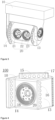
Fig. 2 is a schematic structural view of a camera assembly provided by one of the embodiments of the present invention; -
Fig. 3 is a schematic structural view of a camera assembly provided by another embodiment of the present invention; -
Fig. 4 is a schematic structural view of a camera assembly provided by yet another embodiment of the present invention. - In order to make the present invention readily understood, a more particular description of the invention will be rendered by reference to accompanying drawings and specific embodiments. It needs to be noted that when an element is referred to as being "secured" to another element, it can be directly on another element or one or more intervening elements may be present in between. When one element is referred to as being "connected" to another element, it can be directly connected to another element or one or more intervening elements may be present in between. As used in the description, the orientations or positional relationships indicated by the terms "up", "down", "inside", "outside", "vertical", "horizontal" and the like are based on the orientations or positional relationships shown in the drawings for purposes of describing the invention and simplifying the description only, and are not intended to indicate or imply that the referenced apparatus or element must have a particular orientation or be constructed and operated in a particular orientation. It is therefore not to be understood as limiting the invention. Furthermore, the terms "first", "second", and the like are used for descriptive purposes only and are not to be construed as indicating or implying relative importance.
- Unless defined otherwise, all technical and scientific terms used herein have the same meaning as commonly understood by one of ordinary skill in the art to which this invention belongs. The terminology used herein in the description of the invention herein is for the purpose of describing particular embodiments only and is not to be limiting of the present invention. As used herein, the term "and/or" includes any and all combinations of one or more of the associated listed items.
- Further, the technical features involved in different embodiments of the present invention described below can be combined with each other as long as they do not conflict with each other.
- Referring to
Figs. 1-4 , an embodiment of the present invention provides acamera assembly 100. Thecamera assembly 100 is applicable to a wheel positioning system. For example, as shown inFig. 1 , the wheel positioning system includes thecamera assembly 100, acamera apparatus 200, acalibration apparatus 300, and aprocessing system 400. Thecalibration apparatus 300 is attached to a wheel of the vehicle, thecamera assembly 100 is provided on one side of the vehicle, the visual field range of the camera assembly faces thecalibration apparatus 300 on one side of the vehicle, and thecamera assembly 100 is used to collect the first calibration image of thecalibration apparatus 300 on one side of the vehicle; thecamera apparatus 200 is provided on the other side of the vehicle, the visual field range of thecamera apparatus 200 faces thecalibration apparatus 300 and thecamera assembly 100 on the other side of the vehicle, and thecamera apparatus 200 is used to collect the second calibration image of thecalibration apparatus 300 and the camera image of thecamera assembly 100 on the other side of the vehicle. Theprocessing system 400 is connected to thecamera assembly 100 and thecamera apparatus 200, respectively. Theprocessing system 400 is used for determining the first position of a wheel on one side of the vehicle with respect to thecamera assembly 100 according to the first calibration image, determining the second position of a wheel on the other side of the vehicle with respect to thecamera apparatus 200 according to the second calibration image, determining a relative position of the camera assembly with respect to thecamera apparatus 200 according to the camera image, and determining a position of a wheel of the vehicle according to the first position, the second position, and the relative position. - As shown in
Figs. 1-2 , thecamera assembly 100 includes abase body 10 and a cameramain body 20 mounted to thebase body 10, wherein thebase body 10 is provided with at least two target surfaces, at least two of the target surfaces are not in the same plane, and at least two of the target surfaces are not in the same plane as the surface where the lens in the camera main body is located. At least two target surfaces are respectively provided with atarget element 16, the spatial positional relationship between thetarget element 16 and the cameramain body 20 is known, and the geometric characteristics of thetarget element 16 are known. Thetarget element 16 on the target surface can be used for thecamera apparatus 200 to collect an image, and thetarget element 16 may be a concave or convex geometry. In this embodiment, thetarget element 16 is a circular spot that is concave on the target surface. It could be appreciated that at least two target surfaces are not in the same plane, and may be arranged parallel to each other or at a predetermined angle therebetween. It should be understood that thetarget element 16 may also be in the shape of a polygon, such as a triangle, other geometric shapes, or even a combination of several geometric shapes, in addition to being a circular spot. - In the present embodiment, the target surface on the
base body 10 protrudes outward so that the image data of thetarget elements 16 located on the target surface can be acquired more easily by thecamera apparatus 200. At least two target surfaces can be directed in multiple directions, respectively, and at least three target surfaces are not in the same plane, thereby enabling thebase body 10 to be adapted to multiple collection viewing angles. Therefore, theimage camera apparatus 200 can easily acquire image data. - For example, when the
camera assembly 100 is provided around a wheel on one side of a vehicle and the visual field range of the cameramain body 20 is directed toward the wheel on one side of a vehicle, thecamera apparatus 200 may collect thetarget element 16 of the target surface in thebase body 10 from multiple positions, without needing to be directly in front of the visual field range of the cameramain body 20, as long as it is ensured that thecamera apparatus 200 can collect thetarget element 16 of at least one target surface. Further, since the positional relationship between each of the target surfaces and the cameramain body 20 is known, thecamera apparatus 200 can get to know the position of the cameramain body 20 by indirectly collecting thetarget element 16. It could be understood that when a portion of the target surface on thebase body 10 is obscured, the remainingvisible target element 16 on the target surface can still meet the collected and calculation requirements. Therefore, the wheel positioning system improves the accuracy of positioning by collecting and calculating thetarget element 16 of multiple target surfaces. - It could be understood that when the
base body 10 is provided with at least three target surfaces, two target surfaces may be grouped together so that at least three target surfaces may be divided into multiple groups. Theprocessing system 400 performs the comparison and check computation according to numerical values calculated by different groups of the target surfaces. If the position information about the cameramain body 20 calculated according to each group of the target surfaces is consistent or less than a preset error range, no structural variation occurs to the target surface of thebase body 10 and no inaccurate measurement is resulted in. Thecamera assembly 100 is in a normal state at this moment. Otherwise, if the position information of the cameramain body 20 calculated by each group of the target surfaces is inconsistent or less than a preset error range, the target surface of thebase body 10 has undergone structural variation, such as aging deformation or impact deformation of the target surface. At this time, thecamera assembly 100 is in an abnormal state, and the target surface of thebase body 10 should be replaced or re-calibrated back to a factory. - Specifically, in the present embodiment, the number of at least two target surfaces is two, respectively a
first target surface 13 and asecond target surface 14. The outer shape of thebase body 10 is L-shaped, thebase body 10 comprises afirst step portion 11 and a second step portion 12, one end face of thefirst step portion 11 is provided with thefirst target surface 13, one end face of the second step portion 12 is provided with thesecond target surface 14, thefirst target 13 and thesecond target surface 14 are arranged in parallel, and both thefirst target surface 13 and thesecond target surface 14 face the same direction. The cameramain body 20 is mounted to one end face of thefirst step portion 11, and the surface where the lens of the cameramain body 20 is located is provided at a preset angle to thefirst target surface 13 and thesecond target surface 14. - As could be understood, in some embodiments, the rest end faces of the
first step portion 11 and the second step portion 12 may each be provided with a target surface, and a target element may be provided on these target surfaces correspondingly, i.e. thebase body 10 may be added with a third target surface, even a fourth target surface, etc. as needed, so that thecamera apparatus 200 can collect images of part of the target surfaces of thefirst step portion 11 and the second step portion 12 from more angles, thereby determining the positional relationship of the cameramain body 20 with respect to thecamera apparatus 200. - In some embodiments, the number of the camera
main body 20 is two, respectively a first cameramain body 21 and a second cameramain body 22. The first cameramain body 21 and the second cameramain body 22 are both fixedly mounted to one side end of thefirst step portion 11, and the lens of the first cameramain body 21 and the lens of the second cameramain body 22 are both facing the same direction, so as to collect an image of the calibration apparatus mounted to a wheel. In some other embodiments, the central axis of the lens of the first cameramain body 21 and the central axis of the lens of the second cameramain body 22 are provided at a preset angle, for example, the case where the central axis of the lens of the first cameramain body 21 and the central axis of the lens of the second cameramain body 22 are perpendicular to each other, at which time one of the first cameramain body 21 and the second cameramain body 22 may be used to identify thecalibration apparatus 300 mounted to one side wheel of the vehicle, and the other may be used to collect the position of thecamera apparatus 200 and transmit it to theprocessing system 400. - In some embodiments, the
camera assembly 100 further includes a fixedmount 30 to which the cameramain body 20 is fixedly mounted, the fixedmount 30 being connected to thebase body 10. - In some other embodiments, as shown in
Fig. 3 , thecamera assembly 100 includes abase body 10 and a cameramain body 20 mounted to thebase body 10. Thebase body 10 is provided with afirst target surface 13 and asecond target surface 14, thefirst target surface 13 and thesecond target surface 14 are both provided with atarget element 16, and thefirst target surface 13 and thesecond target surface 14 are parallel to each other. The cameramain body 20 comprises a first cameramain body 21, a second cameramain body 22, and a third cameramain body 23. The first cameramain body 21 and the second cameramain body 22 are mounted to thebase body 10 in parallel, and the lens orientations of the first cameramain body 21 and the second cameramain body 22 are the same, namely, the visual field range of the first cameramain body 21 and the visual field range of the second cameramain body 22 are the same, and the central axis of the third cameramain body 23 is perpendicular to the central axes of the first cameramain body 21 and the second cameramain body 22, respectively so that the third cameramain body 23 can collect images different from the first cameramain body 21 and the second cameramain body 22. It could be understood that, in use, when the first cameramain body 21 and the second cameramain body 22 are used to collect an image of thecalibration apparatus 300, the third cameramain body 23 may be used to collect other images, such as an image of thecamera apparatus 200. Therefore, the wheel positioning system can be more accurately positioned by providing a camera main body of different visual field ranges and view angles. - As shown in
Fig. 4 , thecamera assembly 100 includes abase body 10 and a cameramain body 20 mounted to thebase body 10. Thebase body 10 is provided with at least three target surfaces, the at least three target surfaces not being in the same plane, and at least two target surfaces are not in the same plane as the face where the lens in the cameramain body 20 is located; at least two target surfaces are respectively provided with atarget element 16, the spatial positional relationship between thetarget element 16 and the cameramain body 20 is known, and the geometric characteristics of thetarget element 16 are known. For example, the target surfaces are arranged at a preset angle, and the target surfaces are provided with atarget element 16 whose image is to be collected, thetarget element 16 being concave or convex geometric shapes. In this embodiment, thetarget element 16 is a circular spot that is concave on the target surface. - It could be appreciated that at least two target surfaces are not in the same plane, and may be arranged parallel to each other or at a predetermined angle therebetween. It should be understood that the
target element 16 may also be in the shape of a polygon, such as a triangle, other geometric shapes, or even a combination of several geometric shapes, in addition to being a circular spot. - In the present embodiment, the target surface on the
base body 10 protrudes outward so that the image data of thetarget elements 16 located on the target surface can be acquired more easily by thecamera apparatus 200. At least two target surfaces can be directed in multiple directions, respectively, and at least three target surfaces are not in the same plane, thereby enabling thebase body 10 to be adapted to multiple collection viewing angles. Therefore, theimage camera apparatus 200 can easily acquire image data. - For example, when the
camera assembly 100 is provided around a wheel on one side of a vehicle and the visual field range of the cameramain body 20 is directed toward the wheel on one side of a vehicle, thecamera apparatus 200 may collect thetarget element 16 of the target surface in thebase body 10 from multiple positions, without needing thecamera apparatus 200 to be directly in front of the visual field range of the cameramain body 20, as long as it is ensured that thecamera apparatus 200 can collect thetarget element 16 of at least one target surface. Further, since the positional relationship between each of the target surfaces and the cameramain body 20 is known, thecamera apparatus 200 can get to know the position of the cameramain body 20 by indirectly collecting thetarget element 16. It could be understood that when a portion of the target surface on thebase body 10 is obscured, the remainingvisible target element 16 on the target surface can still meet the collected and calculation requirements. Therefore, the wheel positioning system improves the accuracy of positioning by collecting and calculating thetarget element 16 of multiple target surfaces. - It could be understood that when the
base body 10 is provided with at least three target surfaces, two target surfaces may be grouped together so that at least three target surfaces may be divided into multiple groups. Theprocessing system 400 performs the comparison and check computation according to numerical values calculated by different groups of the target surfaces. If the position information about the cameramain body 20 calculated according to each group of the target surfaces is consistent or less than a preset error range, no structural variation occurs to the target surface of thebase body 10 and no inaccurate measurement is resulted in. Thecamera assembly 100 is in a normal state at this moment. Otherwise, if the position information of the cameramain body 20 calculated by each group of the target surfaces is inconsistent or less than a preset error range, the target surface of thebase body 10 has undergone structural variation, such as aging deformation or impact deformation of the target surface. At this time, thecamera assembly 100 is in an abnormal state, and the target surface of thebase body 10 should be replaced or re-calibrated back to a factory. - Specifically, in the present embodiment, the number of at least three target surfaces is three, respectively a
first target surface 13, asecond target surface 14, and athird target surface 15. Thebase body 10 is a three-dimensional block having multiple outer surfaces, and thebase body 10 comprises a main body and an epitaxial block. The main body is connected to the epitaxial block, one end face of the main body is provided with thefirst target surface 13, the epitaxial block is provided with thesecond target surface 14, the base body extends outward to form aconvex portion 17, and theconvex portion 17 is provided with thethird target surface 15, wherein thefirst target surface 13, thesecond target surface 14, and thethird target surface 15 are arranged at a preset angle in pairs. - It could be understood that the
camera apparatus 200 may be the same structure as thecamera assembly 100, may also be an ordinary camera, and may of course also be other apparatuses for collecting an image as long as the position image of thecamera assembly 100 can be collected. - It should be understood that the above-described
calibration apparatus 300, which is a target plate, is correspondingly provided with a marker element for positioning. The marker element may be a geometric shape such as a circle, a triangle, or a trapezoid, etc. through which the position of the wheel can be known by thecamera assembly 100 and thecamera apparatus 200. - Based on the
camera assembly 100 of the above-described embodiment, in combination with the application scenario shown inFig. 1 , a wheel positioning system is proposed, including thecamera assembly 100, thecamera apparatus 200, thecalibration apparatus 300, and aprocessing system 400. - The
calibration apparatus 300 is attached to a wheel of the vehicle, thecamera assembly 100 is arranged on one side of the vehicle, the visual field range of thecamera assembly 100 faces thecalibration apparatus 300 on one side of the vehicle, and is used for collecting a first calibration image of thecalibration apparatus 300 on one side of the vehicle, thecamera assembly 200 is arranged on the other side of the vehicle, the visual field range of thecamera assembly 200 faces thecalibration apparatus 300 on the other side of the vehicle and thecamera assembly 100, and thecamera apparatus 200 is used for collecting a second calibration image of thecalibration apparatus 300 on the other side of the vehicle and a camera image of thecamera assembly 100; - the
processing system 400 is connected to thecamera assembly 100 and thecamera apparatus 300, respectively; theprocessing system 400 is used for determining the first position of a wheel on one side of the vehicle with respect to thecamera assembly 100 according to the first calibration image, determining the second position of a wheel on the other side of the vehicle with respect to thecamera apparatus 200 according to the second calibration image, determining a relative position of thecamera assembly 100 with respect to thecamera apparatus 200 according to the camera image, and determining a position of a wheel of the vehicle according to the first position, the second position, and the relative position. - In further embodiments, taking two target surfaces as one group of calculating units, the
processing system 400 is further configured to calculate at least two position information of the cameramain body 20 according to the images of thetarget elements 16 of at least two groups of the calculating units; and to compare whether the at least two position information is consistent, and if so, the position of the cameramain body 20 relative to thecamera apparatus 200 is determined according to the position information. - For example, the
camera apparatus 200 acquires an image of thecamera assembly 100 and feeds back the same to theprocessing system 400. Theprocessing system 400 identifies and screens out thefirst target surface 13, thesecond target surface 14, and the third target surface (not shown). At this time, thefirst target surface 13 and thesecond target surface 14 can be taken as the first group, and thefirst target surface 13 and the third target surface can be taken as the second group; if the position information about the cameramain body 20 calculated according to the first group of the target surfaces is consistent with the position information about the cameramain body 20 calculated according to the second group of the target surfaces or is less than a preset error range, it indicates that thecamera assembly 100 complies with a factory state, and the target surface on thecamera assembly 100 does not have a structural variation that causes measurement inaccuracy. - If some of the target surfaces are covered, e.g. the third target surface is partially covered, the target element located on the third target surface cannot be recognized by the
processing system 400, and therefore, theprocessing system 400 can only recognize and obtain image data for thefirst target surface 13 and thesecond target surface 14. When thecamera assembly 100 is placed on one side of the vehicle, some of the target surfaces will be blocked. But some of the target surfaces will be prominent so that the image data thereof are easily collected. Through reasonable design, even if there are individual target surfaces blocked, the remainingtarget element 16 on the visible target surface can still meet the requirements for collection and calculation. Therefore, the wheel positioning system improves the accuracy of positioning by collecting and calculating thetarget element 16 of multiple target surfaces. - Based on the wheel positioning system described above, a method for vehicle wheel positioning is proposed. Specifically, the
calibration apparatus 300 is attached to a wheel of the vehicle, the camera assembly is provided on one side of the vehicle, and the camera apparatus is provided on the other side of the vehicle. The specific steps are:
acquiring a first calibration image, acquired by thecamera assembly 100, of thecalibration apparatus 300 on one side of the vehicle; determining a first position of a wheel on one side of the vehicle relative to thecamera assembly 100 according to the first calibration image; acquiring a second calibration image, acquired by thecamera apparatus 200, of thecalibration apparatus 300 on the other side of the vehicle, and a camera image of thecamera assembly 100; determining the second position of a wheel on the other side of the vehicle relative to thecamera apparatus 200 according to the second calibration image; determining a relative position of thecamera assembly 100 with respect to thecamera apparatus 200 according to the camera image; and determining a position of the vehicle wheel according to the first position, the second position, and the relative position. - Further, the step of determining the relative position of the camera assembly with respect to the camera apparatus according to the camera image further comprises:
calculating position information of the camera assembly relative to the camera apparatus according to images of the target element of at least two groups of calculating units; and comparing whether the position information is consistent; and if so, determining the relative position of the camera assembly with respect to the camera apparatus according to the position information. - In another embodiment, the step of determining the relative position of the camera assembly with respect to the camera apparatus according to the camera image further comprises: screening out images of at least two target surfaces from at least three target surfaces; and determining a relative position of the camera assembly relative to the camera apparatus according to the images of the at least two target surfaces.
- The camera image is an image including the
target element 16 of two target surfaces of the at least three target surfaces on thecamera assembly 100, the two target surfaces being a group of calculating units. - For example, the
camera assembly 100 collects a first calibration image of a calibration apparatus on one side of the vehicle and feeds back the same to theprocessing system 400, and thecamera apparatus 200 collects a second calibration image of a calibration apparatus on the other side of the vehicle and a camera image of thecamera assembly 100 and feeds back the same to theprocessing system 400. Theprocessing system 400 determines the relative position of thecamera assembly 100 with respect to thecamera apparatus 200 according to the camera image, and determines a position of a wheel of the vehicle according to the relative position, the first position, and the second position. - In summary, in the
camera assembly 100 of an embodiment of the present invention, thebase body 10 is provided with at least two target surfaces that are not in the same plane, the target surfaces being provided with atarget element 16 for calibration. Therefore, the positional relationship between the cameramain body 20 and thecamera apparatus 200 can be determined by thetarget element 16 on the target surface of thebase body 10 to enhance the accuracy of the calibration calculation. In addition, when at least three target surfaces are provided, every two target surfaces form one group to form multiple groups of combinations, and the position information of the camera main body is known through multiple groups of combinations and compared so that it can be judged whether the target surface on thecamera assembly 100 also meets the requirements of accurate calibration. Therefore, the failed target surface on thecamera assembly 100 can be replaced in time or repaired. - The above-mentioned description is merely an implementation mode of the present invention, and does not limit the scope of the present invention. Any equivalent structure or equivalent process change made by using the contents of the description and the drawings of the present invention or directly or indirectly used in other relevant technical fields is likewise included in the scope of protection of the present invention.
Claims (16)
- A camera assembly applied in wheel positioning, characterized in that the camera assembly comprises a camera main body and a base body, the base body is provided with at least two target surfaces, the at least two target surfaces are not in a same plane, and at least two target surfaces are not in the same plane as a face where a lens in the camera main body is located;the at least two target surfaces are respectively provided with a target element, a spatial positional relationship between the target element and the camera main body is known, and geometric characteristics of the target element are known;the target element of each of the at least two target surfaces is used for a camera apparatus to determine a position of the camera assembly.
- The camera assembly according to claim 1, characterized in that the number of the camera main body is two, both camera main bodies being mounted to a same side of the base body.
- The camera assembly according to claim 1, characterized in that the base body is a three-dimensional block structure having multiple outer surfaces, wherein the outer surface of the base body is provided with at least two target surfaces.
- The camera assembly according to claim 3, characterized in that the target surface is a plane or a curved surface.
- The camera assembly according to claim 1, characterized in that at least two target surfaces are provided at a pre-set angle therebetween.
- The camera assembly according to claim 1, characterized in that the target element is a geometric pattern that is concave or convex on the target surface.
- The camera assembly according to claim 1, characterized in that the number of the at least two target surfaces is two, respectively a first target surface and a second target surface, the first target surface and the second target surface are arranged in parallel, and the camera main body is located at one side of the base body.
- The camera assembly according to claim 7, characterized in that the camera further comprises a fixed mount, the camera main body being fixedly mounted in the fixed mount and the fixed mount being fixedly connected to the base body.
- The camera assembly according to claim 1, characterized in that a mounting face where the lens in the camera main body is located is perpendicular to at least one target surface.
- The camera assembly according to claim 1, characterized in that the number of the at least two target surfaces is two, respectively a first target surface and a second target surface, an end face of the base body is provided with the first target surface and the second target surface, the base body extends outward to form a convex portion, and the convex portion is provided with a third target surface, wherein the first target surface, the second target surface, and the third target surface are provided at a pre-set angle in pairs.
- A wheel positioning system applied to four-wheel positioning of a vehicle, characterized by comprising a calibration apparatus, a camera apparatus, a processing system, and the camera assembly of any of claims 1-10;wherein the calibration apparatus is attached to a wheel of the vehicle, the camera assembly is provided on one side of the vehicle, a visual field range of the camera assembly is directed to the calibration apparatus on one side of the vehicle and is used for acquiring a first calibration image of the calibration apparatus on one side of the vehicle, the camera apparatus is provided on the other side of the vehicle, the visual field range of the camera apparatus is directed to the calibration apparatus on the other side of the vehicle and the camera assembly, and the camera apparatus is used for acquiring a second calibration image of the calibration apparatus on the other side of the vehicle and a camera image of the camera assembly;the processing system is connected to the camera assembly and the camera apparatus, respectively, the processing system being configured to determine a first position of a wheel on one side of the vehicle relative to the camera assembly according to a first calibration image, to determine a second position of a wheel on the other side of the vehicle relative to the camera apparatus according to the second calibration image, to determine a relative position of the camera assembly with respect to the camera apparatus according to the camera image, and to determine a position of the wheel of the vehicle according to the first position, the second position, and the relative position.
- The system according to claim 11, characterized in that the camera image is an image comprising the target element of two target surfaces of the at least three target surfaces on the camera assembly, the two target surfaces being one group of calculating units;the processing system determines the relative position of the camera assembly with respect to the camera apparatus according to the camera image, specifically as follows:the processing system is used for calculating position information of the camera assembly with respect to the camera apparatus according to images of the target element of at least two groups of calculating units, and comparing whether the position information is consistent, and if so, determining the relative position of the camera assembly relative to the camera apparatus according to the position information.
- The system according to claim 12, characterized in that the camera image is an image comprising each of the at least three target surfaces on the camera assembly;
the processing system determines the relative position of the camera with respect to the camera apparatus according to the camera image, specifically: screening out images of the at least two target surfaces, and determining the relative position of the camera with respect to the camera apparatus according to the images of the at least two target surfaces. - A method for vehicle wheel positioning, applied to a vehicle positioning system, wherein the vehicle positioning system comprises a calibration apparatus, a camera apparatus, and the camera assembly according to any of claims 1-10, the calibration apparatus being attached to a wheel of the vehicle, the camera assembly being provided on one side of the vehicle, and the camera apparatus being provided on the other side of the vehicle, characterized in that the method comprises:acquiring a first calibration image, acquired by the camera assembly, of the calibration apparatus on one side of the vehicle;determining a first position of a wheel on one side of the vehicle relative to the camera assembly according to the first calibration image;acquiring a second calibration image, acquired by the camera apparatus, of the calibration apparatus on the other side of the vehicle, and a camera image of the camera assembly;determining a second position of the wheel on the other side of the vehicle relative to the camera apparatus according to the second calibration image;determining a relative position of the camera assembly with respect to the camera apparatus according to the camera image;and determining a position of the vehicle wheel according to the first position, the second position, and the relative position.
- The method according to claim 14, characterized in that the camera image is an image comprising the target element of two target surfaces of the at least three target surfaces on the camera assembly, the two target surfaces being one group of calculating units;a step of determining a relative position of the camera assembly with respect to the camera apparatus according to the camera image, further comprises:calculating position information of the camera assembly relative to the camera apparatus according to images of the target element of at least two groups of the calculating units;and comparing whether the position information is consistent;and if so, determining the relative position of the camera assembly with respect to the camera apparatus according to the position information.
- The method according to claim 14, characterized in that the camera image is an image comprising each of the at least three target surfaces on the camera assembly;
a step of determining a relative position of the camera assembly with respect to the camera apparatus according to the camera image, further comprises:screening out images of at least two target surfaces from the at least three target surfaces;and determining the relative position of the camera assembly relative to the camera apparatus according to the images of the at least two target surfaces.
Applications Claiming Priority (2)
| Application Number | Priority Date | Filing Date | Title |
|---|---|---|---|
| CN202010813746.XA CN111879261A (en) | 2020-08-13 | 2020-08-13 | Camera assembly, wheel positioning system and wheel positioning method |
| PCT/CN2021/110806 WO2022033385A1 (en) | 2020-08-13 | 2021-08-05 | Camera assembly, wheel positioning system and method for positioning wheels |
Publications (2)
| Publication Number | Publication Date |
|---|---|
| EP4184114A1 true EP4184114A1 (en) | 2023-05-24 |
| EP4184114A4 EP4184114A4 (en) | 2023-12-13 |
Family
ID=73202627
Family Applications (1)
| Application Number | Title | Priority Date | Filing Date |
|---|---|---|---|
| EP21855438.4A Pending EP4184114A4 (en) | 2020-08-13 | 2021-08-05 | Camera assembly, wheel positioning system and method for positioning wheels |
Country Status (4)
| Country | Link |
|---|---|
| US (1) | US20230199332A1 (en) |
| EP (1) | EP4184114A4 (en) |
| CN (1) | CN111879261A (en) |
| WO (1) | WO2022033385A1 (en) |
Families Citing this family (5)
| Publication number | Priority date | Publication date | Assignee | Title |
|---|---|---|---|---|
| CN111307074A (en) | 2020-04-01 | 2020-06-19 | 深圳市道通科技股份有限公司 | Three-dimensional target, wheel alignment system and wheel alignment method |
| CN111879261A (en) * | 2020-08-13 | 2020-11-03 | 深圳市道通科技股份有限公司 | Camera assembly, wheel positioning system and wheel positioning method |
| CN119085538A (en) * | 2024-09-09 | 2024-12-06 | 深圳市易检车服科技有限公司 | Vehicle detection device and four-wheel alignment instrument |
| CN119085537A (en) * | 2024-09-09 | 2024-12-06 | 深圳市易检车服科技有限公司 | Four-wheel alignment |
| SE547899C2 (en) * | 2025-01-20 | 2025-12-16 | Car O Liner Group Ab | Camera housing arrangement, and wheel alignment measuring arrangement comprising such camera housing arrangement |
Family Cites Families (13)
| Publication number | Priority date | Publication date | Assignee | Title |
|---|---|---|---|---|
| US5724128A (en) * | 1995-12-28 | 1998-03-03 | Hunter Engineering Company | Apparatus and method for determining vehicle wheel alignment measurements from three dimensional wheel positions and orientations |
| US6968282B1 (en) * | 2000-05-22 | 2005-11-22 | Snap-On Incorporated | Self-calibrating, multi-camera machine vision measuring system |
| DE10043354A1 (en) * | 2000-09-02 | 2002-03-14 | Beissbarth Gmbh | Chassis measuring device |
| DE60234308D1 (en) * | 2002-02-04 | 2009-12-24 | Corghi Spa | Device for measuring the characteristic position parameters of a motor vehicle |
| US7953247B2 (en) * | 2007-05-21 | 2011-05-31 | Snap-On Incorporated | Method and apparatus for wheel alignment |
| DE102010039246A1 (en) * | 2010-08-12 | 2012-02-16 | Robert Bosch Gmbh | Method for calibrating a measuring system and device for carrying out the method |
| CN104316335B (en) * | 2014-11-19 | 2017-01-18 | 烟台开发区海德科技有限公司 | 3D automobile wheel positioner multi-camera calibration system and method |
| CN109923371B (en) * | 2016-08-16 | 2021-11-26 | 实耐宝公司 | Wheel alignment method and system |
| CN106949857A (en) * | 2017-03-29 | 2017-07-14 | 鹤山市黑豹电子机械制造有限公司 | A kind of high capacity waggon tire localization method |
| CN106969726A (en) * | 2017-05-16 | 2017-07-21 | 桂林施瑞德科技发展有限公司 | 3D four-wheel aligner for intelligently capturing target image and control method thereof |
| CN111307074A (en) * | 2020-04-01 | 2020-06-19 | 深圳市道通科技股份有限公司 | Three-dimensional target, wheel alignment system and wheel alignment method |
| CN212692809U (en) * | 2020-08-13 | 2021-03-12 | 深圳市道通科技股份有限公司 | Camera assembly and wheel positioning system |
| CN111879261A (en) * | 2020-08-13 | 2020-11-03 | 深圳市道通科技股份有限公司 | Camera assembly, wheel positioning system and wheel positioning method |
-
2020
- 2020-08-13 CN CN202010813746.XA patent/CN111879261A/en active Pending
-
2021
- 2021-08-05 EP EP21855438.4A patent/EP4184114A4/en active Pending
- 2021-08-05 WO PCT/CN2021/110806 patent/WO2022033385A1/en not_active Ceased
-
2023
- 2023-02-12 US US18/167,873 patent/US20230199332A1/en active Pending
Also Published As
| Publication number | Publication date |
|---|---|
| CN111879261A (en) | 2020-11-03 |
| EP4184114A4 (en) | 2023-12-13 |
| WO2022033385A1 (en) | 2022-02-17 |
| US20230199332A1 (en) | 2023-06-22 |
Similar Documents
| Publication | Publication Date | Title |
|---|---|---|
| US20230199332A1 (en) | Camera Assembly, Wheel Positioning System and Method for Positioning Wheels | |
| JP5881969B2 (en) | Optical measurement system | |
| US8368761B2 (en) | Image correction method for camera system | |
| EP2769177B1 (en) | Device and method for measuring the characteristic angles and dimensions of wheels, steering system and chassis of vehicles in general | |
| US8448342B2 (en) | Unit of at least two target arrangements for optically measuring an axle and device for optically measuring an axle | |
| EP1335181B1 (en) | Device for measuring the characteristic attitude parameters of a vehicle | |
| JP5172428B2 (en) | Comprehensive calibration method for stereo vision probe system | |
| US10132666B2 (en) | Apparatus for measuring interior temperature of vehicle using 3D thermal image | |
| KR19980063676A (en) | System for measuring gaps and mismatches between opposing parts | |
| US12188764B2 (en) | Three-dimensional target, wheel positioning system, and wheel positioning method | |
| EP1831642A1 (en) | Non-contact vehicle measurement method and system | |
| CN113256734B (en) | Calibration method, system and electronic equipment for vehicle perception sensor | |
| JP2011209269A (en) | Image pickup apparatus and range obtaining system | |
| JPWO2018135063A1 (en) | Pose estimation method and position pose estimation method using a marker and a marker | |
| CN212692809U (en) | Camera assembly and wheel positioning system | |
| CN110188665B (en) | Image processing method and device and computer equipment | |
| CN211855241U (en) | Three-dimensional target and wheel alignment system | |
| JP2021099722A (en) | Calibration device, imaging apparatus, movable body, and calibration method | |
| CN113237424A (en) | Wheel position measuring method for urban rail vehicle bogie | |
| CN110793495B (en) | Method and device for measuring the shortest distance of the front visual field of a vehicle | |
| CN220085383U (en) | Intelligent hole pin assembly augmented reality device | |
| US20250008070A1 (en) | Imaging device and parallax deviation correction method | |
| CN113766211A (en) | Camera installation angle detection system and method of ADAS equipment | |
| US9702694B2 (en) | Wheel toe and camber measurement system | |
| CN113251922B (en) | Measuring method |
Legal Events
| Date | Code | Title | Description |
|---|---|---|---|
| STAA | Information on the status of an ep patent application or granted ep patent |
Free format text: STATUS: THE INTERNATIONAL PUBLICATION HAS BEEN MADE |
|
| PUAI | Public reference made under article 153(3) epc to a published international application that has entered the european phase |
Free format text: ORIGINAL CODE: 0009012 |
|
| STAA | Information on the status of an ep patent application or granted ep patent |
Free format text: STATUS: REQUEST FOR EXAMINATION WAS MADE |
|
| 17P | Request for examination filed |
Effective date: 20230214 |
|
| AK | Designated contracting states |
Kind code of ref document: A1 Designated state(s): AL AT BE BG CH CY CZ DE DK EE ES FI FR GB GR HR HU IE IS IT LI LT LU LV MC MK MT NL NO PL PT RO RS SE SI SK SM TR |
|
| DAV | Request for validation of the european patent (deleted) | ||
| DAX | Request for extension of the european patent (deleted) | ||
| A4 | Supplementary search report drawn up and despatched |
Effective date: 20231115 |
|
| RIC1 | Information provided on ipc code assigned before grant |
Ipc: G01B 5/00 20060101ALI20231109BHEP Ipc: G01B 11/275 20060101AFI20231109BHEP |
|
| STAA | Information on the status of an ep patent application or granted ep patent |
Free format text: STATUS: EXAMINATION IS IN PROGRESS |
|
| 17Q | First examination report despatched |
Effective date: 20251029 |