EP4184091A1 - Appliance fan assembly - Google Patents
Appliance fan assembly Download PDFInfo
- Publication number
- EP4184091A1 EP4184091A1 EP22196001.6A EP22196001A EP4184091A1 EP 4184091 A1 EP4184091 A1 EP 4184091A1 EP 22196001 A EP22196001 A EP 22196001A EP 4184091 A1 EP4184091 A1 EP 4184091A1
- Authority
- EP
- European Patent Office
- Prior art keywords
- sidewall
- damper member
- impeller
- household refrigerator
- refrigerator appliance
- Prior art date
- Legal status (The legal status is an assumption and is not a legal conclusion. Google has not performed a legal analysis and makes no representation as to the accuracy of the status listed.)
- Withdrawn
Links
- 230000000712 assembly Effects 0.000 description 1
- 238000000429 assembly Methods 0.000 description 1
- 230000000903 blocking effect Effects 0.000 description 1
- 238000000034 method Methods 0.000 description 1
- 239000003507 refrigerant Substances 0.000 description 1
Images




Classifications
-
- F—MECHANICAL ENGINEERING; LIGHTING; HEATING; WEAPONS; BLASTING
- F25—REFRIGERATION OR COOLING; COMBINED HEATING AND REFRIGERATION SYSTEMS; HEAT PUMP SYSTEMS; MANUFACTURE OR STORAGE OF ICE; LIQUEFACTION SOLIDIFICATION OF GASES
- F25D—REFRIGERATORS; COLD ROOMS; ICE-BOXES; COOLING OR FREEZING APPARATUS NOT OTHERWISE PROVIDED FOR
- F25D17/00—Arrangements for circulating cooling fluids; Arrangements for circulating gas, e.g. air, within refrigerated spaces
- F25D17/04—Arrangements for circulating cooling fluids; Arrangements for circulating gas, e.g. air, within refrigerated spaces for circulating air, e.g. by convection
- F25D17/042—Air treating means within refrigerated spaces
- F25D17/045—Air flow control arrangements
-
- F—MECHANICAL ENGINEERING; LIGHTING; HEATING; WEAPONS; BLASTING
- F25—REFRIGERATION OR COOLING; COMBINED HEATING AND REFRIGERATION SYSTEMS; HEAT PUMP SYSTEMS; MANUFACTURE OR STORAGE OF ICE; LIQUEFACTION SOLIDIFICATION OF GASES
- F25D—REFRIGERATORS; COLD ROOMS; ICE-BOXES; COOLING OR FREEZING APPARATUS NOT OTHERWISE PROVIDED FOR
- F25D17/00—Arrangements for circulating cooling fluids; Arrangements for circulating gas, e.g. air, within refrigerated spaces
- F25D17/04—Arrangements for circulating cooling fluids; Arrangements for circulating gas, e.g. air, within refrigerated spaces for circulating air, e.g. by convection
- F25D17/06—Arrangements for circulating cooling fluids; Arrangements for circulating gas, e.g. air, within refrigerated spaces for circulating air, e.g. by convection by forced circulation
- F25D17/062—Arrangements for circulating cooling fluids; Arrangements for circulating gas, e.g. air, within refrigerated spaces for circulating air, e.g. by convection by forced circulation in household refrigerators
-
- F—MECHANICAL ENGINEERING; LIGHTING; HEATING; WEAPONS; BLASTING
- F04—POSITIVE - DISPLACEMENT MACHINES FOR LIQUIDS; PUMPS FOR LIQUIDS OR ELASTIC FLUIDS
- F04D—NON-POSITIVE-DISPLACEMENT PUMPS
- F04D29/00—Details, component parts, or accessories
- F04D29/40—Casings; Connections of working fluid
- F04D29/42—Casings; Connections of working fluid for radial or helico-centrifugal pumps
- F04D29/4206—Casings; Connections of working fluid for radial or helico-centrifugal pumps especially adapted for elastic fluid pumps
- F04D29/4226—Fan casings
- F04D29/4246—Fan casings comprising more than one outlet
-
- F—MECHANICAL ENGINEERING; LIGHTING; HEATING; WEAPONS; BLASTING
- F25—REFRIGERATION OR COOLING; COMBINED HEATING AND REFRIGERATION SYSTEMS; HEAT PUMP SYSTEMS; MANUFACTURE OR STORAGE OF ICE; LIQUEFACTION SOLIDIFICATION OF GASES
- F25D—REFRIGERATORS; COLD ROOMS; ICE-BOXES; COOLING OR FREEZING APPARATUS NOT OTHERWISE PROVIDED FOR
- F25D2317/00—Details or arrangements for circulating cooling fluids; Details or arrangements for circulating gas, e.g. air, within refrigerated spaces, not provided for in other groups of this subclass
- F25D2317/06—Details or arrangements for circulating cooling fluids; Details or arrangements for circulating gas, e.g. air, within refrigerated spaces, not provided for in other groups of this subclass with forced air circulation
- F25D2317/068—Details or arrangements for circulating cooling fluids; Details or arrangements for circulating gas, e.g. air, within refrigerated spaces, not provided for in other groups of this subclass with forced air circulation characterised by the fans
- F25D2317/0681—Details thereof
-
- F—MECHANICAL ENGINEERING; LIGHTING; HEATING; WEAPONS; BLASTING
- F25—REFRIGERATION OR COOLING; COMBINED HEATING AND REFRIGERATION SYSTEMS; HEAT PUMP SYSTEMS; MANUFACTURE OR STORAGE OF ICE; LIQUEFACTION SOLIDIFICATION OF GASES
- F25D—REFRIGERATORS; COLD ROOMS; ICE-BOXES; COOLING OR FREEZING APPARATUS NOT OTHERWISE PROVIDED FOR
- F25D2323/00—General constructional features not provided for in other groups of this subclass
- F25D2323/002—Details for cooling refrigerating machinery
- F25D2323/0028—Details for cooling refrigerating machinery characterised by the fans
- F25D2323/00282—Details for cooling refrigerating machinery characterised by the fans the fans not of the axial type
Definitions
- the present disclosure relates to a fan assembly for use in household appliances such as refrigerators.
- Refrigerators generally may include a fan assembly that controls or regulates the amount of cooled air provided to one or more compartments of the refrigerator.
- the fan assembly may be disposed in a cold air passage to maintain a desired temperature of each compartment.
- the fan assembly may include a frame provided with one or more openings or air passages that may route cooled air to the compartments and a damper that may be rotated by a motor to selectively open or close the air passages.
- the damper may be coaxially arranged between the fan and the frame and may move within a gap between the fan and the frame.
- a fan assembly for use in an appliance.
- the fan assembly may include a housing, an impeller, a first damper member, a second damper member, and an actuation assembly.
- the housing may define a number of outlets and the impeller may be configured to rotate about a rotational axis to direct air towards the number of outlets.
- the first damper member may at least partially extend circumferentially about the impeller and the second damper member may at least partially extend circumferentially about the impeller.
- the actuation assembly may be configured to selectively rotate the first damper member and/or the second damper member to partially block, completely block or completely open the number of outlets.
- an air supply device for use in a refrigerator.
- the refrigerator may include a freezer compartment, a refrigerator compartment, and a convertible compartment.
- the air supply device may include an impeller, a first damper member, a second damper member, and an actuation assembly.
- the impeller may be configured to rotate about a rotational axis to provide direct air towards a number of outlets fluidly that may be connected to the freezer compartment, the refrigerator compartment, and the convertible compartment.
- the first damper member may include a first sidewall that may at least partially extend circumferentially about the impeller.
- the second damper member may at least partially extend circumferentially about the impeller and may be disposed radially between the impeller and the first damper member.
- the actuation assembly may be configured to selectively rotate the first damper member and/or the second damper member to partially block, completely block, or completely open at least one of the number of outlets.
- a refrigerator may include a number of compartments, a panel, an impeller, a number of damper members, and an actuation assembly.
- the number of compartments may be formed by a number of mullions and walls of the refrigerator.
- the panel may be covered by one or more inner walls of the number of compartments.
- the panel may include a base surface and a number of protrusions that may collectively form a number of channels that may each be fluidly connected to one or more compartments of the number of compartments.
- the impeller may be rotationally coupled to the panel and configured to rotate about a rotational axis to direct air towards the number of outlets.
- the number of damper members may at least partially extend circumferentially about the impeller.
- the actuation assembly may be configured to selectively rotate the first damper member and/or the second damper member to partially block, completely block or completely open the number of channels.
- substantially or “about” may be used herein to describe disclosed or claimed embodiments.
- the term “substantially” or “about” may modify a value or relative characteristic disclosed or claimed in the present disclosure. In such instances, “substantially” or “about” may signify that the value or relative characteristic it modifies is within ⁇ 0%, 0.1%, 0.5%, 1%, 2%, 3%, 4%, 5% or 10% of the value or relative characteristic.
- first, second, third, etc. may be used to describe various elements, components, regions, layers and/or sections, these elements, components, regions, layers and/or sections should not be limited by these terms. These terms may be only used to distinguish one element, component, region, layer or section from another region, layer or section. Terms such as “first,” “second,” and other numerical terms when used herein do not imply a sequence or order unless clearly indicated by the context. Thus, a first element, component, region, layer or section discussed below could be termed a second element, component, region, layer or section without departing from the teachings of the example embodiments.
- spatially relative terms such as “inner,” “outer,” “beneath,” “below,” “lower,” “above,” “upper,” and the like, may be used for ease of description to describe one element or feature's relationship to another element(s) or feature(s) as illustrated in the figures. Spatially relative terms may be intended to encompass different orientations of the device in use or operation in addition to the orientation depicted in the figures. For example, if the device in the figures is turned over, elements described as “below” or “beneath” other elements or features would then be oriented “above” the other elements or features. Thus, the example term “below” can encompass both an orientation of above and below. The device may be otherwise oriented (rotated 90 degrees or at other orientations) and the spatially relative descriptors used herein interpreted accordingly.
- FIG. 1 generally shows the refrigerator 100.
- the refrigerator may be of the French-Door Bottom Mount type, but it is understood that this disclosure could apply to any type of refrigerator, such as a side-by-side, two-door bottom mount, or top-mount type.
- the refrigerator 100 may include a number of storage compartments 102.
- the storage compartments may include a first internal storage chamber or a refrigerated compartment 102a, a convertible storage compartment 102b, and a freezer compartment 102c.
- the convertible storage compartment 102b may be disposed between the refrigerator compartment 102a and the freezer compartment 102c.
- the compartments 102 may be arranged in a variety of arrangements.
- Each of the compartments 102 may be divided by a mullion or divider 104 configured to insulate the compartments from one another for independent temperature control. Additionally, one or more of the compartments 102 may be controlled to adjust in temperature such that the compartments 102 may be implemented to store frozen or fresh items.
- a convertible compartment 102d may be implemented in a variety of configurations.
- the convertible compartment 102d may be arranged as a portion of the freezer compartment 102c and may be separated or divided by one of the mullions 104 or dividers to bisect the freezer compartment 102c or divide it into various proportions.
- each of the compartments 102a-102d may be accessible via one or more doors.
- the fresh food compartment doors are designated 106
- the freezer door is designated 108.
- the refrigerated compartment 102a may only have one door 106.
- the temperature of the convertible compartment 102b may be rapidly adjusted over a number of setpoints, which may range from approximately -25 degrees centigrade to 15 degrees centigrade. Such a temperature range may correspond to temperatures that may be implemented to store a variety of goods. However, other temperatures or ranges of temperatures may be implemented and achieved via a controller provided with a memory programmed to adjust the temperature of the convertible compartment 102b. As an example, the controller (not illustrated) may adjust one or more of the damper sidewalls to provide warm or cool air to the convertible compartment 102b.
- a fan assembly 110 for use in the refrigerator 100 is provided.
- the fan assembly include a base member 112 that may be disposed on a wall 114 disposed behind or below one or more of the compartments 102.
- the base member 112 may define an opening in which a fan or impeller 120 extends through.
- the impeller 120 may be configured to rotate about a rotational axis R to direct warm or cool air to a number of outlets 124, 126, 128 that may each be fluidly connected to the compartments 102.
- a number of deflectors 122 may extend from the base member 112 to form one or more ducts or outlets.
- the number of outlets may include a refrigerator outlet 124, that may be fluidly connected to the refrigerator compartment 102a to supply air from the impeller 120 to the refrigerator compartment 102a, a convertible compartment outlet 126, that may be fluidly connected to the convertible compartment 102b to supply air from the impeller 120 to the convertible compartment 102b, and a freezer outlet 128 that may be fluidly connected to the freezer compartment 102c to supply air from the impeller 120 to the freezer compartment 102c.
- the fan assembly 110 may include a first damper member 116 and a second damper member 118.
- the first and second damper members 116, 118 may circumferentially extend about the impeller 120 and an actuation assembly 130 may be operatively connected to the first damper member 116, the second damper member 118, or both.
- the actuation assembly 130 may be configured to selectively rotate the first and second damper members 116, 118 to partially block, completely block, or completely open at least one of the number of outlets 124, 126, 128.
- Blocking one or more of the outlets 124, 126, 128, while opening the other outlets 124, 126, 128, may permit a volume of air that would have been otherwise provided to the other outlets so that the temperature of the compartments 102 fluidly connected to the outlets 124, 126, 128 may raised or lowered as desired in a relatively short period of time.
- the first damper member 116 may include a first annular ring 132 and a first damper sidewall 134 that may extend from the first annular ring 132 and the second damper member 118 may include a second annular ring 136 and a second damper sidewall 138 that may extend from the second annular ring 136.
- the first annular ring 132 may be spaced apart from the base member 112 and the second annular ring may lie along or move along the base member 112.
- the impeller 120 may include a number of vanes 140 and a band 142 that may extend between distal ends of each of the vanes 140 The distal ends of the vanes 140 and/or the band 142 may form an outer periphery of the impeller 120.
- the first sidewall 134 may be radially spaced apart from the outer periphery of the impeller 120 and the second sidewall 138 may be disposed radially between the first sidewall 134 and the impeller 120.
- the first sidewall 134 may include a first circumferential portion 144 and a first tangential portion 146.
- the first circumferential portion 144 may be curved and may extend circumferentially about the outer periphery of the impeller 120 and the first tangential portion 146 may be substantially straight and extend in a substantially tangential direction with respect to the first circumferential portion 144.
- the second sidewall may include a second circumferential portion 148 and a second tangential portion 150.
- the second circumferential portion 148 may be curved and extend circumferentially about the outer periphery of the impeller 120 and the second tangential portion 150 may be substantially straight and extend in a substantially tangential direction with respect to the second circumferential portion 148.
- the first and second tangential portions 146, 150 may be curved and may extend circumferentially about the outer periphery of the impeller 120 and the second tangential portion 150 may be substantially straight and extend in a substantially tangential direction with respect to the second circum
- the fan assembly 110 may include the number of deflectors 122 that may include a first deflector 122a, a second deflector 122b, and a third deflector 122c.
- the first deflector 122a and the second deflector 122b may form the refrigerator outlet 124.
- the first deflector 122a and a first end of the third deflector 122c may form the convertible compartment outlet 126 and a second end of the third deflector 122c and the second deflector 122b may form the freezer compartment outlet 128.
- the first and second deflectors 122a, 122b may be V-shaped and may include first and second arms 152, 154 that may be connected to one another by a curved portion 156.
- the third deflector may include a first distal portion 160, a second distal portion 162, and a medial portion 164 extending therebetween.
- the first and second distal portions 160, 162 may each be substantially straight and the medial portion 164 may be curved so as to circumferentially extend about an outer periphery of the impeller 120.
- first and second damper members 116, 118 may be adjusted by one or more actuation assemblies.
- a first actuation assembly may include a first motor 226 and a first gear 228 that may be operatively coupled to the first motor 226.
- the first gear 228 may be spaced apart from the base member 112 and configured to engage one or more teeth 234 that may be formed by the first annular ring 132.
- a second actuation assembly may include a second motor 230 and a second gear 232 that may be operatively coupled to the second motor 230 and configured to engage one or more teeth 236 of the second annular ring 136.
- Fig. 2 illustrates a perspective view of the fan assembly 110 according to one or more embodiments.
- the fan assembly 110 may include the impeller 120 and the first and second damper members 116, 118 may be disposed in a first position in which the first and second damper members 116, 118 do not block the refrigerator outlet 124, the convertible compartment outlet 126, or the freezer outlet 128 so that each of the outlets 124, 126, 128 are opened.
- the first and second damper members 116, 118 may be arranged coaxial to one another, or concentric to one another, or both.
- the first damper member 116 may include the first annular ring 132 and the first sidewall 134 and the second damper member 118 may include the second annular ring 136 and the second sidewall 138.
- the annular rings 132, 136 may each have a rectangular shape that is bent to extend in the circumferential direction.
- the first sidewall 134 may cover the second sidewall 138 in the radial direction.
- the first sidewall 134 and the second sidewall 138 may each cover the medial portion 164 in the radial direction.
- the first tangential portion 146 may lie against or be adjacent to the second distal portion 162 of the third deflector and the second tangential portion 150 may lie against or be adjacent to the first distal portion 160.
- the first annular ring 132 may be disposed above the second distal portion 162 and the second annular ring 136 may extend below the second distal portion 162.
- the second distal portion 162 may define a slot 158 and the first and second damper members 116, 118 including the first annular ring 132, the first sidewall 134, the second annular ring 136, and the second sidewall 138 move in and out of.
- the first distal portion 160 of the third deflector 122c may define a slot 166 and the first and second damper members 116, 118 including the first annular ring 132, the first sidewall 134, the second annular ring 136, and the second sidewall 138 may move in and out of the slot 166.
- the first motor 226 and the first gear 228 and the second motor 230 and the second gear 232 may each be disposed adjacent to the third deflector 122c. However, the first and second motors 226, 230 and the first and second gears 228, 232 may each be coupled to the base member 112 in one or more other suitable positions so that the first and second gears 228, 232 may engage the teeth 234, 236 of the first and second annular rings 132, 136.
- Fig. 3 illustrates a plan view of the fan assembly 110 provided with the first and second damper members 116, 118 in a second position, in which the convertible compartment outlet 126 is closed and the refrigerator compartment outlet 124 and freezer compartment outlet 128 are each open.
- first and second damper members 116, 118 are in the second position, portions of the first sidewall 134 may at least partially overlap or cover the second sidewall 138.
- the first annular ring 132 may be disposed above, such as in the axial direction, and radially inward with respect to the second sidewall 138.
- the first tangential portion 146 may extend in a direction that is substantially parallel to the first deflection member 122a to direct air towards the second arm 154 and the refrigerator outlet 124.
- the first tangential portion 146 may be positioned to prevent or block air flowing to the convertible compartment outlet 126.
- Fig. 4 illustrates a plan view of the fan assembly 110 provided with the first and second damper members 116, 118 in a third position, in which the freezer compartment outlet 128 is open and the refrigerator outlet 124 and the convertible compartment 126 are closed.
- the first tangential portion 146 and the second tangential portion 150 may contact one another to close a gap disposed between the first circumferential portion 144 and the second circumferential portion 148.
- the second sidewall 138 may block the freezer compartment outlet 128 and the first sidewall 134 may block the convertible compartment outlet 126.
- Fig. 5 illustrates a plan view of the fan assembly 110 provided with the first and second damper members 116, 118 in a fourth position, in which the refrigerator compartment outlet 124 is open and the convertible compartment 126 and the freezer outlet 128 are each closed.
- the second sidewall 138 may block the freezer compartment outlet 127 and the first sidewall 134 may block the convertible compartment 126.
- Fig. 6 illustrates a plan view of the fan assembly 110 provided with the first and second damper members 116, 118 in a fifth position, in which the convertible compartment outlet 126 is open and the refrigerator compartment outlet 124 and the freezer outlet 128 are each closed.
- the second sidewall 138 may block the refrigerator compartment outlet 124 and the first sidewall 134 may block the freezer compartment outlet 128.
- the second tangential portion 150 may extend towards the curved portion 156 of the first deflector 122a.
- the second tangential portion 150 may be configured to direct air towards the first deflector 122a and the freezer compartment outlet 128.
- Fig. 7 illustrates a perspective view of the fan assembly 110 provided with the first and second damper members 116, 118 in a sixth position, in which the convertible compartment outlet 126 and the refrigerator compartment outlet 124 are each open and the freezer compartment outlet 128 is closed.
- the second sidewall 138 may block the freezer compartment outlet 128 and the first sidewall 134 may be positioned to radially cover or overlap portions of the third deflector 122c.
- the second tangential portion 150 of the second sidewall 138 may extend towards the second arm 154 of the second deflector 122b so that air is directed towards the second deflector 122b and the refrigerator outlet 124.
- Fig. 8 illustrates a perspective view of the fan assembly 110 provided with the first and second damper members 116, 118 in a seventh position, in which the convertible compartment outlet 126 and the freezer compartment outlet 128 are each open and the refrigerator compartment outlet 124 is closed.
- the second sidewall 138 may block the refrigerator compartment outlet 124 and the first sidewall 134 may be positioned to radially cover or overlap portions of the third deflector 122c.
- the second tangential portion 150 of the second sidewall 138 may extend towards or parallel to the first leg 153 of the first deflector 122a so that air is directed towards the first deflector 122a and the convertible compartment outlet 126.
- the second sidewall 138 may be spaced apart from an inner periphery 168 of the second annular ring 136.
- Fig. 9 illustrates a perspective view of a portion of the refrigerator 100 that includes a panel 170 and an exemplary fan assembly 210.
- the base member 112 may be disposed on the panel 170 and the impeller 120 may be rotationally coupled to the panel 170 and extend through the base member 112.
- a number of deflectors 172 may be fixed to the base member 112 to form the refrigerator compartment outlet 124, the convertible compartment outlet 126, and the freezer compartment outlet 128.
- the number of deflectors 172 may include a first deflector 172a, a second deflector 172b, and a third deflector 172c.
- the panel 170 may include a number of protrusions 174 and the number of protrusions 174 and the number of deflectors 172 may collectively form the refrigerator compartment outlet 124, the convertible compartment outlet 126, and the freezer compartment outlet 128.
- the number of protrusions may include a first protrusion 174a that may include a first segment 176 and a second segment 178 that may be arranged substantially orthogonally to the first segment 176.
- the first segment 176 may form an inner periphery of the refrigerator outlet compartment 126 and may include an inner surface and an outer surface, the inner surface spaced closer to the impeller 120 than the outer surface.
- the outer surface may be curved, and the inner surface may be relatively straight. The curved outer surface may be configured to mitigate or prevent turbulent air flow through the refrigerator compartment outlet 126.
- a second protrusion 174b may be disposed between the first deflector 172a and the first protrusion 174a.
- the second protrusion 174b may be connected e.g., integrally formed to the first protrusion 174a.
- the second protrusion 174b may include a curved surface 180 that may be adjacent to or contact the first deflector 172a.
- the first and second protrusions 174a, 174b may be spaced on a first side of the refrigerator compartment outlet 124 and a third protrusion 174c may be disposed on a second side of the refrigerator compartment outlet 124.
- the third protrusion 174c may have a flat-bottom airfoil shape provided with a curved inner surface, 182 that may face the impeller 120, and a flat surface that may form or face an outer periphery 186 of the panel 170.
- the panel 170 may include a fourth protrusion 174d that may be spaced apart from the third protrusion 174c away from the outer periphery 186.
- the fourth protrusion may have a substantially triangular shape including a vertex 188 and a base 190.
- the vertex 188 may be disposed closer to the impeller 120 than the base 190.
- the panel 170 may include a fifth protrusion 174e that may be spaced apart from the first protrusion 174a on the other side of the convertible compartment outlet 126.
- the fifth protrusion 174e may include a first section 192, that may extend in a direction that is parallel to the second section 178 of the first protrusion 174a, and a second section 194 that may extend substantially orthogonally to the first section 194.
- the protrusions 174 may form one or more channels 181, 182, 195 that may be fluidly connected to the outlets 124, 126, 128.
- the third protrusion 174c and the fourth protrusion 174d may form a first channel 181 that may be fluidly connected to the freezer compartment outlet 126.
- the second protrusion 174b and the third protrusion 174c may collectively form a second channel that may be fluidly connected to the refrigerant compartment outlet 124.
- the first protrusion 174a and the fifth protrusion 174e may form a third channel 182 that may be fluidly connected to the convertible compartment outlet 126.
- a damper member 196 may be rotationally fixed to the base 112 and configured to selectively rotate to partially block, completely block or completely open the number of outlets 124, 126, 128.
- the damper member 196 may include an annular ring 198 and a sidewall 200 that may extend from an inner periphery 202 of the annular ring.
- Fig. 10 illustrates a perspective view of a portion of the refrigerator 100 that includes an exemplary panel 204 and an exemplary fan assembly 212.
- One or more deflectors 206 may extend from the base member 112, including a first deflector 206a, a second deflector 206b, and a third deflector 206c.
- the first deflector 206a may include a first leg 208 and a second leg 209 that may extend orthogonally the first leg 208.
- the second deflector 206b may include a curved portion 214, a first radial extending portion 216, and a second radial extending portion 218.
- the first and second radial extending portions 216, 218 may each extend from ends of the curved portion 214.
- the third deflector 206c may include a first radial extending portion 220, a second radial extending portion 224, and a curved portion 222 that may extend therebetween.
Landscapes
- Engineering & Computer Science (AREA)
- Mechanical Engineering (AREA)
- General Engineering & Computer Science (AREA)
- Chemical & Material Sciences (AREA)
- Combustion & Propulsion (AREA)
- Physics & Mathematics (AREA)
- Thermal Sciences (AREA)
- Cold Air Circulating Systems And Constructional Details In Refrigerators (AREA)
Abstract
Description
- The present disclosure relates to a fan assembly for use in household appliances such as refrigerators.
- Refrigerators generally may include a fan assembly that controls or regulates the amount of cooled air provided to one or more compartments of the refrigerator. The fan assembly may be disposed in a cold air passage to maintain a desired temperature of each compartment. The fan assembly may include a frame provided with one or more openings or air passages that may route cooled air to the compartments and a damper that may be rotated by a motor to selectively open or close the air passages. The damper may be coaxially arranged between the fan and the frame and may move within a gap between the fan and the frame.
- According to one embodiment, a fan assembly for use in an appliance is provided. The fan assembly may include a housing, an impeller, a first damper member, a second damper member, and an actuation assembly. The housing may define a number of outlets and the impeller may be configured to rotate about a rotational axis to direct air towards the number of outlets. The first damper member may at least partially extend circumferentially about the impeller and the second damper member may at least partially extend circumferentially about the impeller. The actuation assembly may be configured to selectively rotate the first damper member and/or the second damper member to partially block, completely block or completely open the number of outlets.
- According to another embodiment, an air supply device for use in a refrigerator is provided. The refrigerator may include a freezer compartment, a refrigerator compartment, and a convertible compartment. The air supply device may include an impeller, a first damper member, a second damper member, and an actuation assembly. The impeller may be configured to rotate about a rotational axis to provide direct air towards a number of outlets fluidly that may be connected to the freezer compartment, the refrigerator compartment, and the convertible compartment. The first damper member may include a first sidewall that may at least partially extend circumferentially about the impeller. The second damper member may at least partially extend circumferentially about the impeller and may be disposed radially between the impeller and the first damper member. The actuation assembly may be configured to selectively rotate the first damper member and/or the second damper member to partially block, completely block, or completely open at least one of the number of outlets.
- According to yet another embodiment, a refrigerator is provided. The refrigerator may include a number of compartments, a panel, an impeller, a number of damper members, and an actuation assembly. The number of compartments may be formed by a number of mullions and walls of the refrigerator. The panel may be covered by one or more inner walls of the number of compartments. The panel may include a base surface and a number of protrusions that may collectively form a number of channels that may each be fluidly connected to one or more compartments of the number of compartments. The impeller may be rotationally coupled to the panel and configured to rotate about a rotational axis to direct air towards the number of outlets. The number of damper members may at least partially extend circumferentially about the impeller. The actuation assembly may be configured to selectively rotate the first damper member and/or the second damper member to partially block, completely block or completely open the number of channels.
-
-
FIG. 1 illustrates a front-perspective view of an exemplary refrigerator. -
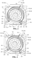
FIG. 2 illustrates a perspective view of an exemplary fan assembly provided with damper members in a first position. -
FIG. 3 illustrates a perspective view of the exemplary fan assembly provided with damper members in a second position. -
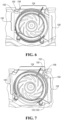
FIG. 4 illustrates a perspective view of the exemplary fan assembly provided with damper members in a third position. -
FIG. 5 illustrates a perspective view of the exemplary fan assembly provided with damper members in a fourth position. -
FIG. 6 illustrates a perspective view of the exemplary fan assembly provided with damper members in a fifth position. -
FIG. 7 illustrates a perspective view of the exemplary fan assembly provided with damper members in a sixth position. -
FIG. 8 illustrates a perspective view of the exemplary fan assembly provided with damper members in a seventh position. -
FIG. 9 illustrates a perspective view of another exemplary fan assembly. -
FIG. 10 illustrates a perspective view of another exemplary fan assembly. - As required, detailed embodiments of the present invention are disclosed herein; however, it is to be understood that the disclosed embodiments are merely exemplary of the invention that may be embodied in various and alternative forms. The figures are not necessarily to scale; some features may be exaggerated or minimized to show details of particular components. Therefore, specific structural and functional details disclosed herein are not to be interpreted as limiting, but merely as a representative basis for teaching one skilled in the art to variously employ the present invention.
- This invention is not limited to the specific embodiments and methods described below, as specific components and/or conditions may, of course, vary. Furthermore, the terminology used herein is used only for the purpose of describing particular embodiments of the present invention and is not intended to be limiting in any way.
- As used in the specification and the appended claims, the singular form "a," "an," and "the" comprise plural referents unless the context clearly indicates otherwise. For example, reference to a component in the singular is intended to comprise a plurality of components.
- The term "substantially" or "about" may be used herein to describe disclosed or claimed embodiments. The term "substantially" or "about" may modify a value or relative characteristic disclosed or claimed in the present disclosure. In such instances, "substantially" or "about" may signify that the value or relative characteristic it modifies is within ± 0%, 0.1%, 0.5%, 1%, 2%, 3%, 4%, 5% or 10% of the value or relative characteristic.
- When an element or layer is referred to as being "on," "engaged to," "connected to," or "coupled to" another element or layer, it may be directly on, engaged, connected or coupled to the other element or layer, or intervening elements or layers may be present. In contrast, when an element is referred to as being "directly on," "directly engaged to," "directly connected to," or "directly coupled to" another element or layer, there may be no intervening elements or layers present. Other words used to describe the relationship between elements should be interpreted in a like fashion (e.g., "between" versus "directly between," "adjacent" versus "directly adjacent," etc.). The term "and/or" includes any and all combinations of one or more of the associated listed items.
- Although the terms first, second, third, etc. may be used to describe various elements, components, regions, layers and/or sections, these elements, components, regions, layers and/or sections should not be limited by these terms. These terms may be only used to distinguish one element, component, region, layer or section from another region, layer or section. Terms such as "first," "second," and other numerical terms when used herein do not imply a sequence or order unless clearly indicated by the context. Thus, a first element, component, region, layer or section discussed below could be termed a second element, component, region, layer or section without departing from the teachings of the example embodiments.
- Spatially relative terms, such as "inner," "outer," "beneath," "below," "lower," "above," "upper," and the like, may be used for ease of description to describe one element or feature's relationship to another element(s) or feature(s) as illustrated in the figures. Spatially relative terms may be intended to encompass different orientations of the device in use or operation in addition to the orientation depicted in the figures. For example, if the device in the figures is turned over, elements described as "below" or "beneath" other elements or features would then be oriented "above" the other elements or features. Thus, the example term "below" can encompass both an orientation of above and below. The device may be otherwise oriented (rotated 90 degrees or at other orientations) and the spatially relative descriptors used herein interpreted accordingly.
-
Figure 1 generally shows therefrigerator 100. The refrigerator may be of the French-Door Bottom Mount type, but it is understood that this disclosure could apply to any type of refrigerator, such as a side-by-side, two-door bottom mount, or top-mount type. As shown inFigure 1 , therefrigerator 100 may include a number of storage compartments 102. The storage compartments may include a first internal storage chamber or a refrigerated compartment 102a, a convertible storage compartment 102b, and a freezer compartment 102c. The convertible storage compartment 102b, may be disposed between the refrigerator compartment 102a and the freezer compartment 102c. However, the compartments 102 may be arranged in a variety of arrangements. Each of the compartments 102 may be divided by a mullion ordivider 104 configured to insulate the compartments from one another for independent temperature control. Additionally, one or more of the compartments 102 may be controlled to adjust in temperature such that the compartments 102 may be implemented to store frozen or fresh items. - Though the convertible compartment 102b is depicted in
FIG. 1 as being positioned between the refrigerator compartment 102a and the freezer compartment 102c, a convertible compartment 102d may be implemented in a variety of configurations. For example, in some instances, the convertible compartment 102d may be arranged as a portion of the freezer compartment 102c and may be separated or divided by one of themullions 104 or dividers to bisect the freezer compartment 102c or divide it into various proportions. In general, each of the compartments 102a-102d may be accessible via one or more doors. As shown, the fresh food compartment doors are designated 106, and the freezer door is designated 108. It may also be shown that the refrigerated compartment 102a may only have onedoor 106. As example, each of the compartments 102 divided by seals that may interact with themullions 104 to insulate the compartments 102 from each other. Accordingly, therefrigerator 100 may be flexibly implemented in a variety of configurations. - The temperature of the convertible compartment 102b may be rapidly adjusted over a number of setpoints, which may range from approximately -25 degrees centigrade to 15 degrees centigrade. Such a temperature range may correspond to temperatures that may be implemented to store a variety of goods. However, other temperatures or ranges of temperatures may be implemented and achieved via a controller provided with a memory programmed to adjust the temperature of the convertible compartment 102b. As an example, the controller (not illustrated) may adjust one or more of the damper sidewalls to provide warm or cool air to the convertible compartment 102b.
- Referring generally to the figures, a
fan assembly 110 for use in therefrigerator 100 is provided. The fan assembly include abase member 112 that may be disposed on awall 114 disposed behind or below one or more of the compartments 102. Thebase member 112 may define an opening in which a fan orimpeller 120 extends through. Theimpeller 120 may be configured to rotate about a rotational axis R to direct warm or cool air to a number ofoutlets - A number of deflectors 122 may extend from the
base member 112 to form one or more ducts or outlets. As an example, the number of outlets may include arefrigerator outlet 124, that may be fluidly connected to the refrigerator compartment 102a to supply air from theimpeller 120 to the refrigerator compartment 102a, aconvertible compartment outlet 126, that may be fluidly connected to the convertible compartment 102b to supply air from theimpeller 120 to the convertible compartment 102b, and afreezer outlet 128 that may be fluidly connected to the freezer compartment 102c to supply air from theimpeller 120 to the freezer compartment 102c. - The
fan assembly 110 may include afirst damper member 116 and asecond damper member 118. The first andsecond damper members impeller 120 and an actuation assembly 130 may be operatively connected to thefirst damper member 116, thesecond damper member 118, or both. The actuation assembly 130 may be configured to selectively rotate the first andsecond damper members outlets outlets other outlets outlets - In one or more embodiments, the
first damper member 116 may include a firstannular ring 132 and afirst damper sidewall 134 that may extend from the firstannular ring 132 and thesecond damper member 118 may include a second annular ring 136 and asecond damper sidewall 138 that may extend from the second annular ring 136. As an example, the firstannular ring 132 may be spaced apart from thebase member 112 and the second annular ring may lie along or move along thebase member 112. Theimpeller 120 may include a number of vanes 140 and a band 142 that may extend between distal ends of each of the vanes 140 The distal ends of the vanes 140 and/or the band 142 may form an outer periphery of theimpeller 120. Thefirst sidewall 134 may be radially spaced apart from the outer periphery of theimpeller 120 and thesecond sidewall 138 may be disposed radially between thefirst sidewall 134 and theimpeller 120. - The
first sidewall 134 may include a firstcircumferential portion 144 and a firsttangential portion 146. The firstcircumferential portion 144 may be curved and may extend circumferentially about the outer periphery of theimpeller 120 and the firsttangential portion 146 may be substantially straight and extend in a substantially tangential direction with respect to the firstcircumferential portion 144. The second sidewall may include a secondcircumferential portion 148 and a secondtangential portion 150. The secondcircumferential portion 148 may be curved and extend circumferentially about the outer periphery of theimpeller 120 and the secondtangential portion 150 may be substantially straight and extend in a substantially tangential direction with respect to the secondcircumferential portion 148. The first and secondtangential portions - The
fan assembly 110 may include the number of deflectors 122 that may include a first deflector 122a, a second deflector 122b, and a third deflector 122c. The first deflector 122a and the second deflector 122b may form therefrigerator outlet 124. The first deflector 122a and a first end of the third deflector 122c may form theconvertible compartment outlet 126 and a second end of the third deflector 122c and the second deflector 122b may form thefreezer compartment outlet 128. The first and second deflectors 122a, 122b may be V-shaped and may include first andsecond arms curved portion 156. Alternatively or additionally, the third deflector may include a firstdistal portion 160, a seconddistal portion 162, and amedial portion 164 extending therebetween. As an example, the first and seconddistal portions medial portion 164 may be curved so as to circumferentially extend about an outer periphery of theimpeller 120. - In one or more embodiments, the first and
second damper members first motor 226 and afirst gear 228 that may be operatively coupled to thefirst motor 226. Thefirst gear 228 may be spaced apart from thebase member 112 and configured to engage one or more teeth 234 that may be formed by the firstannular ring 132. A second actuation assembly may include asecond motor 230 and asecond gear 232 that may be operatively coupled to thesecond motor 230 and configured to engage one or more teeth 236 of the second annular ring 136. -
Fig. 2 illustrates a perspective view of thefan assembly 110 according to one or more embodiments. Thefan assembly 110 may include theimpeller 120 and the first andsecond damper members second damper members refrigerator outlet 124, theconvertible compartment outlet 126, or thefreezer outlet 128 so that each of theoutlets second damper members first damper member 116 may include the firstannular ring 132 and thefirst sidewall 134 and thesecond damper member 118 may include the second annular ring 136 and thesecond sidewall 138. The annular rings 132, 136 may each have a rectangular shape that is bent to extend in the circumferential direction. - When the first and
second damper members first sidewall 134 may cover thesecond sidewall 138 in the radial direction. Alternatively or additionally, thefirst sidewall 134 and thesecond sidewall 138 may each cover themedial portion 164 in the radial direction. As an example, the firsttangential portion 146 may lie against or be adjacent to the seconddistal portion 162 of the third deflector and the secondtangential portion 150 may lie against or be adjacent to the firstdistal portion 160. In one or more embodiments, the firstannular ring 132 may be disposed above the seconddistal portion 162 and the second annular ring 136 may extend below the seconddistal portion 162. As another example, the seconddistal portion 162 may define aslot 158 and the first andsecond damper members annular ring 132, thefirst sidewall 134, the second annular ring 136, and thesecond sidewall 138 move in and out of. In one or more embodiments, the firstdistal portion 160 of the third deflector 122c may define aslot 166 and the first andsecond damper members annular ring 132, thefirst sidewall 134, the second annular ring 136, and thesecond sidewall 138 may move in and out of theslot 166. - The
first motor 226 and thefirst gear 228 and thesecond motor 230 and thesecond gear 232 may each be disposed adjacent to the third deflector 122c. However, the first andsecond motors second gears base member 112 in one or more other suitable positions so that the first andsecond gears annular rings 132, 136. -
Fig. 3 illustrates a plan view of thefan assembly 110 provided with the first andsecond damper members convertible compartment outlet 126 is closed and therefrigerator compartment outlet 124 andfreezer compartment outlet 128 are each open. When the first andsecond damper members first sidewall 134 may at least partially overlap or cover thesecond sidewall 138. The firstannular ring 132 may be disposed above, such as in the axial direction, and radially inward with respect to thesecond sidewall 138. The firsttangential portion 146 may extend in a direction that is substantially parallel to the first deflection member 122a to direct air towards thesecond arm 154 and therefrigerator outlet 124. The firsttangential portion 146 may be positioned to prevent or block air flowing to theconvertible compartment outlet 126. -
Fig. 4 illustrates a plan view of thefan assembly 110 provided with the first andsecond damper members freezer compartment outlet 128 is open and therefrigerator outlet 124 and theconvertible compartment 126 are closed. When the first andsecond damper members tangential portion 146 and the secondtangential portion 150 may contact one another to close a gap disposed between the firstcircumferential portion 144 and the secondcircumferential portion 148. As an example, thesecond sidewall 138 may block thefreezer compartment outlet 128 and thefirst sidewall 134 may block theconvertible compartment outlet 126. -
Fig. 5 illustrates a plan view of thefan assembly 110 provided with the first andsecond damper members refrigerator compartment outlet 124 is open and theconvertible compartment 126 and thefreezer outlet 128 are each closed. As an example, thesecond sidewall 138 may block the freezer compartment outlet 127 and thefirst sidewall 134 may block theconvertible compartment 126. -
Fig. 6 illustrates a plan view of thefan assembly 110 provided with the first andsecond damper members convertible compartment outlet 126 is open and therefrigerator compartment outlet 124 and thefreezer outlet 128 are each closed. As an example, thesecond sidewall 138 may block therefrigerator compartment outlet 124 and thefirst sidewall 134 may block thefreezer compartment outlet 128. The secondtangential portion 150 may extend towards thecurved portion 156 of the first deflector 122a. The secondtangential portion 150 may be configured to direct air towards the first deflector 122a and thefreezer compartment outlet 128. -
Fig. 7 illustrates a perspective view of thefan assembly 110 provided with the first andsecond damper members convertible compartment outlet 126 and therefrigerator compartment outlet 124 are each open and thefreezer compartment outlet 128 is closed. As an example, thesecond sidewall 138 may block thefreezer compartment outlet 128 and thefirst sidewall 134 may be positioned to radially cover or overlap portions of the third deflector 122c. The secondtangential portion 150 of thesecond sidewall 138 may extend towards thesecond arm 154 of the second deflector 122b so that air is directed towards the second deflector 122b and therefrigerator outlet 124. -
Fig. 8 illustrates a perspective view of thefan assembly 110 provided with the first andsecond damper members convertible compartment outlet 126 and thefreezer compartment outlet 128 are each open and therefrigerator compartment outlet 124 is closed. As an example, thesecond sidewall 138 may block therefrigerator compartment outlet 124 and thefirst sidewall 134 may be positioned to radially cover or overlap portions of the third deflector 122c. The secondtangential portion 150 of thesecond sidewall 138 may extend towards or parallel to the first leg 153 of the first deflector 122a so that air is directed towards the first deflector 122a and theconvertible compartment outlet 126. - In one or more embodiments, the
second sidewall 138 may be spaced apart from aninner periphery 168 of the second annular ring 136. -
Fig. 9 illustrates a perspective view of a portion of therefrigerator 100 that includes apanel 170 and anexemplary fan assembly 210. Thebase member 112 may be disposed on thepanel 170 and theimpeller 120 may be rotationally coupled to thepanel 170 and extend through thebase member 112. A number of deflectors 172 may be fixed to thebase member 112 to form therefrigerator compartment outlet 124, theconvertible compartment outlet 126, and thefreezer compartment outlet 128. As an example, the number of deflectors 172 may include a first deflector 172a, a second deflector 172b, and a third deflector 172c. - The
panel 170 may include a number of protrusions 174 and the number of protrusions 174 and the number of deflectors 172 may collectively form therefrigerator compartment outlet 124, theconvertible compartment outlet 126, and thefreezer compartment outlet 128. As an example, the number of protrusions may include a first protrusion 174a that may include afirst segment 176 and a second segment 178 that may be arranged substantially orthogonally to thefirst segment 176. Thefirst segment 176 may form an inner periphery of therefrigerator outlet compartment 126 and may include an inner surface and an outer surface, the inner surface spaced closer to theimpeller 120 than the outer surface. As an example, the outer surface may be curved, and the inner surface may be relatively straight. The curved outer surface may be configured to mitigate or prevent turbulent air flow through therefrigerator compartment outlet 126. - A second protrusion 174b may be disposed between the first deflector 172a and the first protrusion 174a. For example, the second protrusion 174b may be connected e.g., integrally formed to the first protrusion 174a. The second protrusion 174b may include a curved surface 180 that may be adjacent to or contact the first deflector 172a. The first and second protrusions 174a, 174b may be spaced on a first side of the
refrigerator compartment outlet 124 and a third protrusion 174c may be disposed on a second side of therefrigerator compartment outlet 124. The third protrusion 174c may have a flat-bottom airfoil shape provided with a curved inner surface, 182 that may face theimpeller 120, and a flat surface that may form or face anouter periphery 186 of thepanel 170. - In one or more embodiments, the
panel 170 may include a fourth protrusion 174d that may be spaced apart from the third protrusion 174c away from theouter periphery 186. As an example, the fourth protrusion may have a substantially triangular shape including avertex 188 and abase 190. Thevertex 188 may be disposed closer to theimpeller 120 than thebase 190. Thepanel 170 may include a fifth protrusion 174e that may be spaced apart from the first protrusion 174a on the other side of theconvertible compartment outlet 126. As an example, the fifth protrusion 174e may include afirst section 192, that may extend in a direction that is parallel to the second section 178 of the first protrusion 174a, and a second section 194 that may extend substantially orthogonally to the first section 194. - The protrusions 174 may form one or
more channels outlets first channel 181 that may be fluidly connected to thefreezer compartment outlet 126. The second protrusion 174b and the third protrusion 174c may collectively form a second channel that may be fluidly connected to therefrigerant compartment outlet 124. The first protrusion 174a and the fifth protrusion 174e may form athird channel 182 that may be fluidly connected to theconvertible compartment outlet 126. - A
damper member 196 may be rotationally fixed to thebase 112 and configured to selectively rotate to partially block, completely block or completely open the number ofoutlets damper member 196 may include an annular ring 198 and asidewall 200 that may extend from an inner periphery 202 of the annular ring. -
Fig. 10 illustrates a perspective view of a portion of therefrigerator 100 that includes anexemplary panel 204 and anexemplary fan assembly 212. One or more deflectors 206 may extend from thebase member 112, including a first deflector 206a, a second deflector 206b, and a third deflector 206c. As an example, the first deflector 206a may include afirst leg 208 and asecond leg 209 that may extend orthogonally thefirst leg 208. The second deflector 206b may include acurved portion 214, a firstradial extending portion 216, and a secondradial extending portion 218. The first and secondradial extending portions curved portion 214. The third deflector 206c may include a firstradial extending portion 220, a secondradial extending portion 224, and acurved portion 222 that may extend therebetween. - While exemplary embodiments are described above, it is not intended that these embodiments describe all possible forms of the invention. Rather, the words used in the specification are words of description rather than limitation, and it is understood that various changes may be made without departing from the spirit and scope of the invention. Additionally, the features of various implementing embodiments may be combined to form further embodiments of the invention.
Claims (14)
- A household refrigerator appliance (100) comprising a fan assembly (110), the fan assembly (110) including a housing defining one or more outlets (124, 126, 128), the fan assembly (110) comprising:an impeller (120) configured to rotate about a rotational axis to direct air towards the one or more outlets (124, 126, 128);a first damper member (116) at least partially extending circumferentially about the impeller (120);a second damper member (118) at least partially extending circumferentially about the impeller (120); andan actuation assembly (130) configured to selectively rotate the first damper member (116) or the second damper member (118) to partially block, completely block or completely open the one or more outlets (124, 126, 128).
- The household refrigerator appliance (100) of claim 1, further comprising:
a base member (112), wherein the impeller (120) is disposed on the base member (112) and the first damper member (116) includes a first annular ring (132) and a first sidewall, wherein the first annular ring (132) is spaced apart from the base member (112) and the first sidewall (134) extends from the first annular ring (132) towards the base member (112). - The household refrigerator appliance (100) of claim 2, wherein the second damper member (118) includes a second annular ring (136) and a second sidewall (138), wherein the second annular ring (136) lies along the base member (112) and the second sidewall (138) extends from the second annular ring (136).
- The household refrigerator appliance (100) of claim 3, wherein the first sidewall (134) is radially spaced apart from an outer periphery of the impeller (120).
- The household refrigerator appliance (100) of claim 4, wherein the second sidewall (138) is disposed radially inward from the first sidewall (134).
- The household refrigerator appliance (100) of claim 5, wherein the actuation assembly (130) is configured to rotate the first damper member (116) and the second damper member (118) to an open position, in which each the second sidewall (138) radially covers the first sidewall (134).
- The household refrigerator appliance (100) of claim 4, wherein the first sidewall (134) includes a first portion (144) and a second portion (146), wherein the first portion (144) extends in a circumferential direction with respect to an outer periphery of the impeller (120) and the second portion (146) extends in a first tangential direction tangential to the circumferential direction.
- The household refrigerator appliance (100) of claim 6, wherein the second sidewall (138) includes a first portion (148) and a second portion (150), wherein the first portion (148) extends in the circumferential direction and the second portion (150) extends in a second tangential direction tangential to the circumferential direction.
- The household refrigerator appliance (100) of claim 7, wherein the actuation assembly (130) is configured to rotate the first damper member (116) and the second damper member (118) to a first position, in which the first damper member (116) blocks a first outlet (124) of the number of outlets (124, 126, 128) and the second damper member (118) blocks a second outlet (126) of the number of outlets (124, 126, 128), and the second portion (146) of the first sidewall (134) and the second portion (150) of the second sidewall (138) contact one another.
- The household refrigerator appliance (100) of claim 1, wherein the appliance (100) is a refrigerator (100).
- The household refrigerator appliance (100) of claim 1, further comprising:one or more compartments (102) formed by a number of mullions (104) and walls of the refrigerator (100);a panel (170) covered by one or more inner walls of the number of compartments, wherein the panel (170) includes a base surface and a number of protrusions (174) collectively forming a number of channels (181, 182, 195) each fluidly connected to one or more compartments (102) of the number of compartments (102);the impeller (120) rotationally coupled to the panel (170) and configured to rotate about the rotational axis to direct air towards the one or more outlets (124, 126, 128); andthe actuation assembly (130) configured to selectively rotate the first damper member (116) and/or the second damper member (118) to partially block, completely block or completely open the one or more channels (181, 182, 195).
- The household refrigerator appliance (100) of claim 11, wherein a first protrusion (174a) and a second protrusion (174b) of the number of protrusions (174) collectively form a first channel of the one or more channels (181, 182, 195), wherein the first and second protrusions (174a, 174b) each have flat portion and a curved portion collectively forming a flat-bottom airfoil shape.
- The household refrigerator appliance (100) of claim 12, wherein the second protrusion (174b) and a third protrusion (174c) form a second channel of the number of channels (181, 182, 195), wherein the second protrusion (174b) has a substantially triangular shape.
- The household refrigerator appliance (100) of claim 13, wherein the third protrusion (174c) includes a vertex (188) and a base (190), and the vertex (188) is disposed closer to the impeller (120) than the base (190).
Applications Claiming Priority (1)
| Application Number | Priority Date | Filing Date | Title |
|---|---|---|---|
| US17/528,449 US11994333B2 (en) | 2021-11-17 | 2021-11-17 | Appliance fan assembly |
Publications (1)
| Publication Number | Publication Date |
|---|---|
| EP4184091A1 true EP4184091A1 (en) | 2023-05-24 |
Family
ID=83361156
Family Applications (1)
| Application Number | Title | Priority Date | Filing Date |
|---|---|---|---|
| EP22196001.6A Withdrawn EP4184091A1 (en) | 2021-11-17 | 2022-09-15 | Appliance fan assembly |
Country Status (2)
| Country | Link |
|---|---|
| US (1) | US11994333B2 (en) |
| EP (1) | EP4184091A1 (en) |
Citations (4)
| Publication number | Priority date | Publication date | Assignee | Title |
|---|---|---|---|---|
| CN204404473U (en) * | 2014-12-22 | 2015-06-17 | 宁波奥克斯空调有限公司 | Air-supply arrangement |
| CN204404472U (en) * | 2014-12-22 | 2015-06-17 | 宁波奥克斯空调有限公司 | Air-supply arrangement and air-conditioning thereof |
| CN208588146U (en) * | 2018-06-27 | 2019-03-08 | 青岛海尔股份有限公司 | Wind cooling refrigerator and its air door masking device |
| CN110530096A (en) * | 2019-09-24 | 2019-12-03 | 合肥晶弘电器有限公司 | Air door mechanism and refrigerator |
Family Cites Families (19)
| Publication number | Priority date | Publication date | Assignee | Title |
|---|---|---|---|---|
| KR100498386B1 (en) | 2002-12-06 | 2005-07-01 | 엘지전자 주식회사 | Apparatus for supply the cool air of refrigerator |
| CN106168426B (en) | 2015-08-28 | 2018-03-23 | 青岛海尔股份有限公司 | Branch air-supply arrangement and the refrigerator with the branch air-supply arrangement |
| CN106196840B (en) * | 2015-08-28 | 2018-02-02 | 青岛海尔股份有限公司 | Branch air-supply arrangement and the refrigerator with the branch air-supply arrangement |
| CN106196837B (en) | 2015-09-24 | 2018-07-13 | 青岛海尔股份有限公司 | Refrigerator |
| CN105650980B (en) | 2016-03-09 | 2018-04-20 | 青岛海尔股份有限公司 | Refrigerator and the branch air-supply arrangement for refrigerator |
| CN105758093B (en) | 2016-03-09 | 2018-04-20 | 青岛海尔股份有限公司 | Refrigerator and the branch air-supply arrangement for refrigerator |
| CN106194804B (en) | 2016-08-31 | 2022-03-25 | 海尔智家股份有限公司 | Centrifugal fan |
| CN106679287A (en) | 2016-12-22 | 2017-05-17 | 青岛海尔股份有限公司 | Air volume regulation device of refrigerator |
| US10372531B2 (en) | 2017-01-05 | 2019-08-06 | Texas Instruments Incorporated | Error-correcting code memory |
| WO2018128946A1 (en) | 2017-01-06 | 2018-07-12 | Pcms Holdings, Inc. | Method for providing vulnerable road user warnings in a blind spot of a parked vehicle |
| CN106958980B (en) | 2017-04-14 | 2019-12-10 | 青岛海尔股份有限公司 | Air outlet device and refrigerator with same |
| CN107421202B (en) | 2017-06-29 | 2019-10-01 | 青岛海尔股份有限公司 | Refrigerator cooling control method and computer storage medium |
| CN108050751A (en) | 2017-12-29 | 2018-05-18 | 青岛海尔股份有限公司 | Split air supply device and refrigerator |
| CN110906609B (en) | 2018-09-17 | 2021-12-21 | 重庆海尔制冷电器有限公司 | Air-cooled refrigerator |
| CN110906610B (en) | 2018-09-17 | 2022-01-21 | 重庆海尔制冷电器有限公司 | Air-cooled refrigerator |
| CN110906614B (en) | 2018-09-17 | 2021-11-26 | 海尔智家股份有限公司 | Air-cooled refrigerator |
| CN109556343B (en) | 2018-12-27 | 2023-12-22 | 江苏凯德电控科技有限公司 | A multi-wind door device |
| JP7291381B2 (en) | 2019-05-24 | 2023-06-15 | アクア株式会社 | Shielding device and refrigerator with same |
| JP7296621B2 (en) | 2019-05-24 | 2023-06-23 | アクア株式会社 | Shielding device and refrigerator with same |
-
2021
- 2021-11-17 US US17/528,449 patent/US11994333B2/en active Active
-
2022
- 2022-09-15 EP EP22196001.6A patent/EP4184091A1/en not_active Withdrawn
Patent Citations (4)
| Publication number | Priority date | Publication date | Assignee | Title |
|---|---|---|---|---|
| CN204404473U (en) * | 2014-12-22 | 2015-06-17 | 宁波奥克斯空调有限公司 | Air-supply arrangement |
| CN204404472U (en) * | 2014-12-22 | 2015-06-17 | 宁波奥克斯空调有限公司 | Air-supply arrangement and air-conditioning thereof |
| CN208588146U (en) * | 2018-06-27 | 2019-03-08 | 青岛海尔股份有限公司 | Wind cooling refrigerator and its air door masking device |
| CN110530096A (en) * | 2019-09-24 | 2019-12-03 | 合肥晶弘电器有限公司 | Air door mechanism and refrigerator |
Also Published As
| Publication number | Publication date |
|---|---|
| US20230152023A1 (en) | 2023-05-18 |
| US11994333B2 (en) | 2024-05-28 |
Similar Documents
| Publication | Publication Date | Title |
|---|---|---|
| AU2019204582B2 (en) | Device having multiple air flow paths and refrigerator having same | |
| KR0152148B1 (en) | A refrigerator | |
| US20080256964A1 (en) | Refrigerator and controlling method of the same | |
| CN100402956C (en) | Flow-through rotary damper providing compartment selection for a multi-compartment refrigerator | |
| KR200143520Y1 (en) | A refrigerator | |
| JP2007120802A (en) | refrigerator | |
| JPH11101556A (en) | Refrigerator equipped with a cold air outlet opening / closing device | |
| US20230213267A1 (en) | Cooling assembly for refrigerator appliance | |
| US11994333B2 (en) | Appliance fan assembly | |
| US12098878B2 (en) | Appliance fan assembly | |
| US12025364B2 (en) | Refrigerator cooling system | |
| EP3978842A1 (en) | Shielding device and refrigerator having same | |
| KR100208357B1 (en) | Refrigerator and its control method with cooling air dispenser | |
| US20080156010A1 (en) | Refrigerator | |
| CN113906264A (en) | Shielding device and refrigerator with same | |
| CN108253689B (en) | air-cooled refrigerator | |
| US11874052B2 (en) | Selective air flow system for a refrigerator appliance | |
| EP3978844B1 (en) | Refrigerator comprising a shielding device for opening or closing air passages | |
| KR100208360B1 (en) | Refrigerator with cooling air dispenser | |
| KR20250068159A (en) | grille-fan assembly and refrigerator having the grille-fan assembly | |
| KR100573816B1 (en) | Damper and Damper Control Method for Kimchi Refrigerator | |
| JP2014114988A (en) | Cold air shutter | |
| KR100208362B1 (en) | Refrigerator with cooling air dispenser | |
| KR200180230Y1 (en) | Refrigerator | |
| BR102023000245A2 (en) | REFRIGERATOR COOLING SYSTEM |
Legal Events
| Date | Code | Title | Description |
|---|---|---|---|
| PUAI | Public reference made under article 153(3) epc to a published international application that has entered the european phase |
Free format text: ORIGINAL CODE: 0009012 |
|
| STAA | Information on the status of an ep patent application or granted ep patent |
Free format text: STATUS: THE APPLICATION HAS BEEN PUBLISHED |
|
| AK | Designated contracting states |
Kind code of ref document: A1 Designated state(s): AL AT BE BG CH CY CZ DE DK EE ES FI FR GB GR HR HU IE IS IT LI LT LU LV MC MK MT NL NO PL PT RO RS SE SI SK SM TR |
|
| STAA | Information on the status of an ep patent application or granted ep patent |
Free format text: STATUS: REQUEST FOR EXAMINATION WAS MADE |
|
| P01 | Opt-out of the competence of the unified patent court (upc) registered |
Effective date: 20231110 |
|
| 17P | Request for examination filed |
Effective date: 20231124 |
|
| RBV | Designated contracting states (corrected) |
Designated state(s): AL AT BE BG CH CY CZ DE DK EE ES FI FR GB GR HR HU IE IS IT LI LT LU LV MC MK MT NL NO PL PT RO RS SE SI SK SM TR |
|
| STAA | Information on the status of an ep patent application or granted ep patent |
Free format text: STATUS: THE APPLICATION HAS BEEN WITHDRAWN |
|
| 18W | Application withdrawn |
Effective date: 20240625 |