EP4184086A1 - Refrigeration circuit and refrigeration device - Google Patents
Refrigeration circuit and refrigeration device Download PDFInfo
- Publication number
- EP4184086A1 EP4184086A1 EP21918131.0A EP21918131A EP4184086A1 EP 4184086 A1 EP4184086 A1 EP 4184086A1 EP 21918131 A EP21918131 A EP 21918131A EP 4184086 A1 EP4184086 A1 EP 4184086A1
- Authority
- EP
- European Patent Office
- Prior art keywords
- phase refrigerant
- gas
- refrigerant
- flows
- liquid
- Prior art date
- Legal status (The legal status is an assumption and is not a legal conclusion. Google has not performed a legal analysis and makes no representation as to the accuracy of the status listed.)
- Pending
Links
Images


Classifications
-
- F—MECHANICAL ENGINEERING; LIGHTING; HEATING; WEAPONS; BLASTING
- F25—REFRIGERATION OR COOLING; COMBINED HEATING AND REFRIGERATION SYSTEMS; HEAT PUMP SYSTEMS; MANUFACTURE OR STORAGE OF ICE; LIQUEFACTION SOLIDIFICATION OF GASES
- F25B—REFRIGERATION MACHINES, PLANTS OR SYSTEMS; COMBINED HEATING AND REFRIGERATION SYSTEMS; HEAT PUMP SYSTEMS
- F25B43/00—Arrangements for separating or purifying gases or liquids; Arrangements for vaporising the residuum of liquid refrigerant, e.g. by heat
- F25B43/04—Arrangements for separating or purifying gases or liquids; Arrangements for vaporising the residuum of liquid refrigerant, e.g. by heat for withdrawing non-condensible gases
- F25B43/043—Arrangements for separating or purifying gases or liquids; Arrangements for vaporising the residuum of liquid refrigerant, e.g. by heat for withdrawing non-condensible gases for compression type systems
-
- F—MECHANICAL ENGINEERING; LIGHTING; HEATING; WEAPONS; BLASTING
- F25—REFRIGERATION OR COOLING; COMBINED HEATING AND REFRIGERATION SYSTEMS; HEAT PUMP SYSTEMS; MANUFACTURE OR STORAGE OF ICE; LIQUEFACTION SOLIDIFICATION OF GASES
- F25B—REFRIGERATION MACHINES, PLANTS OR SYSTEMS; COMBINED HEATING AND REFRIGERATION SYSTEMS; HEAT PUMP SYSTEMS
- F25B39/00—Evaporators; Condensers
- F25B39/02—Evaporators
-
- F—MECHANICAL ENGINEERING; LIGHTING; HEATING; WEAPONS; BLASTING
- F25—REFRIGERATION OR COOLING; COMBINED HEATING AND REFRIGERATION SYSTEMS; HEAT PUMP SYSTEMS; MANUFACTURE OR STORAGE OF ICE; LIQUEFACTION SOLIDIFICATION OF GASES
- F25B—REFRIGERATION MACHINES, PLANTS OR SYSTEMS; COMBINED HEATING AND REFRIGERATION SYSTEMS; HEAT PUMP SYSTEMS
- F25B39/00—Evaporators; Condensers
- F25B39/04—Condensers
-
- F—MECHANICAL ENGINEERING; LIGHTING; HEATING; WEAPONS; BLASTING
- F25—REFRIGERATION OR COOLING; COMBINED HEATING AND REFRIGERATION SYSTEMS; HEAT PUMP SYSTEMS; MANUFACTURE OR STORAGE OF ICE; LIQUEFACTION SOLIDIFICATION OF GASES
- F25B—REFRIGERATION MACHINES, PLANTS OR SYSTEMS; COMBINED HEATING AND REFRIGERATION SYSTEMS; HEAT PUMP SYSTEMS
- F25B40/00—Subcoolers, desuperheaters or superheaters
-
- F—MECHANICAL ENGINEERING; LIGHTING; HEATING; WEAPONS; BLASTING
- F25—REFRIGERATION OR COOLING; COMBINED HEATING AND REFRIGERATION SYSTEMS; HEAT PUMP SYSTEMS; MANUFACTURE OR STORAGE OF ICE; LIQUEFACTION SOLIDIFICATION OF GASES
- F25B—REFRIGERATION MACHINES, PLANTS OR SYSTEMS; COMBINED HEATING AND REFRIGERATION SYSTEMS; HEAT PUMP SYSTEMS
- F25B43/00—Arrangements for separating or purifying gases or liquids; Arrangements for vaporising the residuum of liquid refrigerant, e.g. by heat
-
- F—MECHANICAL ENGINEERING; LIGHTING; HEATING; WEAPONS; BLASTING
- F25—REFRIGERATION OR COOLING; COMBINED HEATING AND REFRIGERATION SYSTEMS; HEAT PUMP SYSTEMS; MANUFACTURE OR STORAGE OF ICE; LIQUEFACTION SOLIDIFICATION OF GASES
- F25B—REFRIGERATION MACHINES, PLANTS OR SYSTEMS; COMBINED HEATING AND REFRIGERATION SYSTEMS; HEAT PUMP SYSTEMS
- F25B5/00—Compression machines, plants or systems, with several evaporator circuits, e.g. for varying refrigerating capacity
- F25B5/02—Compression machines, plants or systems, with several evaporator circuits, e.g. for varying refrigerating capacity arranged in parallel
-
- F—MECHANICAL ENGINEERING; LIGHTING; HEATING; WEAPONS; BLASTING
- F28—HEAT EXCHANGE IN GENERAL
- F28D—HEAT-EXCHANGE APPARATUS, NOT PROVIDED FOR IN ANOTHER SUBCLASS, IN WHICH THE HEAT-EXCHANGE MEDIA DO NOT COME INTO DIRECT CONTACT
- F28D9/00—Heat-exchange apparatus having stationary plate-like or laminated conduit assemblies for both heat-exchange media, the media being in contact with different sides of a conduit wall
- F28D9/0031—Heat-exchange apparatus having stationary plate-like or laminated conduit assemblies for both heat-exchange media, the media being in contact with different sides of a conduit wall the conduits for one heat-exchange medium being formed by paired plates touching each other
- F28D9/0043—Heat-exchange apparatus having stationary plate-like or laminated conduit assemblies for both heat-exchange media, the media being in contact with different sides of a conduit wall the conduits for one heat-exchange medium being formed by paired plates touching each other the plates having openings therein for circulation of at least one heat-exchange medium from one conduit to another
-
- F—MECHANICAL ENGINEERING; LIGHTING; HEATING; WEAPONS; BLASTING
- F28—HEAT EXCHANGE IN GENERAL
- F28D—HEAT-EXCHANGE APPARATUS, NOT PROVIDED FOR IN ANOTHER SUBCLASS, IN WHICH THE HEAT-EXCHANGE MEDIA DO NOT COME INTO DIRECT CONTACT
- F28D9/00—Heat-exchange apparatus having stationary plate-like or laminated conduit assemblies for both heat-exchange media, the media being in contact with different sides of a conduit wall
- F28D9/0062—Heat-exchange apparatus having stationary plate-like or laminated conduit assemblies for both heat-exchange media, the media being in contact with different sides of a conduit wall the conduits for one heat-exchange medium being formed by spaced plates with inserted elements
-
- F—MECHANICAL ENGINEERING; LIGHTING; HEATING; WEAPONS; BLASTING
- F28—HEAT EXCHANGE IN GENERAL
- F28D—HEAT-EXCHANGE APPARATUS, NOT PROVIDED FOR IN ANOTHER SUBCLASS, IN WHICH THE HEAT-EXCHANGE MEDIA DO NOT COME INTO DIRECT CONTACT
- F28D9/00—Heat-exchange apparatus having stationary plate-like or laminated conduit assemblies for both heat-exchange media, the media being in contact with different sides of a conduit wall
- F28D9/0093—Multi-circuit heat-exchangers, e.g. integrating different heat exchange sections in the same unit or heat-exchangers for more than two fluids
-
- F—MECHANICAL ENGINEERING; LIGHTING; HEATING; WEAPONS; BLASTING
- F25—REFRIGERATION OR COOLING; COMBINED HEATING AND REFRIGERATION SYSTEMS; HEAT PUMP SYSTEMS; MANUFACTURE OR STORAGE OF ICE; LIQUEFACTION SOLIDIFICATION OF GASES
- F25B—REFRIGERATION MACHINES, PLANTS OR SYSTEMS; COMBINED HEATING AND REFRIGERATION SYSTEMS; HEAT PUMP SYSTEMS
- F25B2400/00—Component parts or details not otherwise provided for in this subclass
- F25B2400/05—Compression system with heat exchange between particular parts of the system
- F25B2400/054—Compression system with heat exchange between particular parts of the system between the suction tube of the compressor and another part of the cycle
-
- F—MECHANICAL ENGINEERING; LIGHTING; HEATING; WEAPONS; BLASTING
- F25—REFRIGERATION OR COOLING; COMBINED HEATING AND REFRIGERATION SYSTEMS; HEAT PUMP SYSTEMS; MANUFACTURE OR STORAGE OF ICE; LIQUEFACTION SOLIDIFICATION OF GASES
- F25B—REFRIGERATION MACHINES, PLANTS OR SYSTEMS; COMBINED HEATING AND REFRIGERATION SYSTEMS; HEAT PUMP SYSTEMS
- F25B2400/00—Component parts or details not otherwise provided for in this subclass
- F25B2400/23—Separators
-
- F—MECHANICAL ENGINEERING; LIGHTING; HEATING; WEAPONS; BLASTING
- F25—REFRIGERATION OR COOLING; COMBINED HEATING AND REFRIGERATION SYSTEMS; HEAT PUMP SYSTEMS; MANUFACTURE OR STORAGE OF ICE; LIQUEFACTION SOLIDIFICATION OF GASES
- F25B—REFRIGERATION MACHINES, PLANTS OR SYSTEMS; COMBINED HEATING AND REFRIGERATION SYSTEMS; HEAT PUMP SYSTEMS
- F25B41/00—Fluid-circulation arrangements
- F25B41/30—Expansion means; Dispositions thereof
- F25B41/37—Capillary tubes
-
- F—MECHANICAL ENGINEERING; LIGHTING; HEATING; WEAPONS; BLASTING
- F28—HEAT EXCHANGE IN GENERAL
- F28D—HEAT-EXCHANGE APPARATUS, NOT PROVIDED FOR IN ANOTHER SUBCLASS, IN WHICH THE HEAT-EXCHANGE MEDIA DO NOT COME INTO DIRECT CONTACT
- F28D21/00—Heat-exchange apparatus not covered by any of the groups F28D1/00 - F28D20/00
- F28D2021/0019—Other heat exchangers for particular applications; Heat exchange systems not otherwise provided for
- F28D2021/0068—Other heat exchangers for particular applications; Heat exchange systems not otherwise provided for for refrigerant cycles
Definitions
- the present disclosure relates to a refrigeration circuit and a refrigeration device.
- a refrigeration circuit includes a heat exchanger for cooling circulating refrigerant so as to obtain the temperature of the refrigerant required at an evaporator.
- PTL 1 discloses a refrigeration circuit including a flow divider for separating gas and liquid, and a double tube heat exchanger for exchanging heat between the vapor phase refrigerant flowed out from the flow divider, and the liquid phase refrigerant flowed out from the flow divider and the refrigerant returning to the compressor from the evaporator.
- an object of the present disclosure is to reduce the size of a heat exchanger and improve the heat exchanging efficiency in a refrigeration circuit and a refrigeration device.
- a refrigeration circuit in the present disclosure includes: a gas-liquid separator into which a gas-liquid two-phase refrigerant flowed out from a condenser flows, the gas-liquid separator being configured to separate the gas-liquid two-phase refrigerant into a vapor phase refrigerant and a liquid phase refrigerant; and a plate heat exchanger including a first heat exchanging part and a second heat exchanging part, the first heat exchanging part being a part where the vapor phase refrigerant flowed out from the gas-liquid separator and the liquid phase refrigerant flowed out from the gas-liquid separator exchange heat, the second heat exchanging part being a part where the vapor phase refrigerant flowed out from the first heat exchanging part and a returning refrigerant flowed out from an evaporator exchange heat.
- a refrigeration device in the present disclosure includes the above-described refrigeration circuit.
- Refrigeration circuit 1 according to an embodiment of the present disclosure is described below with reference to the drawings.
- Refrigeration circuit 1 is used for a refrigeration device such as an ultra-low-temperature freezer.
- refrigeration circuit 1 includes compressor 10, condenser 11, dryer 12, gas-liquid separator 13, first decompressor 14, plate heat exchanger 20, second decompressor 15, double tube heat exchanger 16, and evaporator 17.
- a gas-liquid two-phase refrigerant which is a mixture of a vapor phase refrigerant and a liquid phase refrigerant, enters gas-liquid separator 13, and gas-liquid separator 13 separates the gas-liquid two-phase refrigerant into a vapor phase refrigerant and a liquid phase refrigerant.
- the vapor phase refrigerant flows out from the upper part of gas-liquid separator 13.
- the liquid phase refrigerant flows out from the lower part of gas-liquid separator 13.
- First decompressor 14 is a capillary tube, for example.
- Plate heat exchanger 20 includes first heat exchanging part 20a and second heat exchanging part 20b.
- First heat exchanging part 20a exchanges heat between the vapor phase refrigerant flowed out from gas-liquid separator 13, and a mixed refrigerant of a returning refrigerant and the liquid phase refrigerant flowed out from gas-liquid separator 13.
- the returning refrigerant is a refrigerant flowing out from evaporator 17 and returning to compressor 10.
- Second heat exchanging part 20b exchanges heat between the vapor phase refrigerant flowed out from first heat exchanging part 20a and the returning refrigerant flowed out from evaporator 17. Details of plate heat exchanger 20 are described later.
- Second decompressor 15 is a capillary tube, for example.
- the returning refrigerant flowed out from evaporator 17 flows through outer pipe 16a of double tube heat exchanger 16. That is, in double tube heat exchanger 16, the returning refrigerant and the refrigerant flowing through second decompressor 15 exchange heat.
- the refrigerant illustrated in FIG 1 circulates in the arrow direction. More specifically, the refrigerant flows through compressor 10, condenser 11 and dryer 12 in this order, and then flows into gas-liquid separator 13. The refrigerant is separated into a vapor phase refrigerant and a liquid phase refrigerant at gas-liquid separator 13.
- the vapor phase refrigerant flowed out from gas-liquid separator 13 flows through first heat exchanging part 20a, second heat exchanging part 20b, second decompressor 15 and evaporator 17 in this order. Further, the returning refrigerant flowed out from evaporator 17 flows through outer pipe 16a of double tube heat exchanger 16 and second heat exchanging part 20b in this order.
- the returning refrigerant flowed out from second heat exchanging part 20b flows out from gas-liquid separator 13, merges at confluence part 18a with the liquid phase refrigerant flowed through first decompressor 14, and returns to compressor 10 through first heat exchanging part 20a.
- the gas-liquid two-phase refrigerant is a mixture of a vapor phase refrigerant and a liquid phase refrigerant. More specifically, the gas-liquid two-phase refrigerant is a mixture of one or more refrigerants respectively selected from among the liquid phase refrigerant listed in the group A and the vapor phase refrigerant listed in the group B shown in Table 1.
- the liquid phase refrigerant is a refrigerant with a boiling point of -55°C or higher, and liquefies before flowing into gas-liquid separator 13.
- the vapor phase refrigerant is a refrigerant with a boiling point lower than -55°C.
- R508B Refrigerant made by mixing trifluoromethane (R23) and hexafluoroethane (R116) at 46wt% and 54wt%. -86.9 R170 Ethane -89.0 R744 Carbon dioxide -78.4 R14 Tetrafluoromethane -128.1 R-1150 Ethylene -104.0 Kr Krypton -152.3 R50 Methane -161.5 R740 Argon -185.8
- plate heat exchanger 20 details of plate heat exchanger 20 are described with reference to FIGS. 2 to 5 .
- the upper side and lower side in FIG 2 are the upper side and lower side of plate heat exchanger 20.
- the left side and right side are the left side and right side of plate heat exchanger 20, and the near side and depth side in the drawing are the front side and rear side of plate heat exchanger 20.
- Plate heat exchanger 20 is a brazed plate heat exchanger.
- Plate heat exchanger 20 includes a plurality of heat transfer plates 21 and cover plates 22. Twelve heat transfer plates 21 are provided in the present embodiment. Heat transfer plate 21 and cover plate 22 are examples of "plate”. Heat transfer plate 21 and cover plate 22 are plate members with a rectangular shape in front view.
- the plurality of heat transfer plates 21 is disposed side by side along the front-rear direction with their plate surfaces parallel to each other and with a predetermined distance therebetween ( FIG. 3 ). In this manner, channel R through which refrigerant flows is formed between heat transfer plates 21 adjacent to each other. More specifically, first channel R1 to eleventh channel R11 are formed in this order from the front side to the rear side.
- second channel R2 and fourth channel R4 are formed so as to be communicated with each other ( FIG. 4 ). Further, second and fourth channels R2 and 4 are formed so as not to communicate with adjacent channel R. More specifically, in third heat transfer plate 21c making up second channel R2, protruding part 21c1 protruding in a columnar shape toward adjacent fourth heat transfer plate 21d making up fourth channel R4 and through hole 21c2 formed at the protruding end of protruding part 21c1 are formed.
- Through hole 21c2 is communicated with through hole 21d1 formed in fourth heat transfer plate 21d.
- the peripheries of through holes 21c2 and 21d1 are in contact with each other and welded.
- second channel R2 and fourth channel R4 communicate with each other, and do not communicate with third channel R3 located between second and fourth channels R2 and R4.
- channels R adjacent to each other in fourth, sixth, eighth, tenth channels R4, R6, R8 and R10 are configured to communicate with each other.
- channels R adjacent to each other in first, third and fifth channels R1, R3 and R5 are configured to communicate with each other.
- channels R adjacent to each other in seventh, ninth and eleventh channels R7, R9 and R11 are configured to communicate with each other. Note that the above-described channels R adjacent to each other are configured to communicate with each other on the upper side and lower side of heat transfer plate 21, except between sixth channel R6 and eighth channel R8. The part between sixth channel R6 and eighth channel R8 are configured to communicate on the upper side of heat transfer plate 21.
- Cover plate 22 is disposed at the front ends and rear ends of the plurality of heat transfer plates 21 disposed side by side. Each cover plate 22 is disposed such that the plate surfaces of each cover plate 22 and opposite heat transfer plate 21 are in contact with each other.
- first connection pipe 23a, second connection pipe 23b and third connection pipe 23c are disposed at the plate surface of first cover plate 22a.
- First and second connection pipes 23a and 23b are disposed side by side in the left-right direction on the lower side of first cover plate 22a.
- Third connection pipe 23c is disposed on the upper side of second connection pipe 23b.
- First connection pipe 23a is an example of "vapor phase refrigerant inflow part”.
- Second connection pipe 23b is an example of "liquid phase refrigerant inflow part”.
- Third connection pipe 23c is an example of "liquid phase refrigerant outflow part”.
- fourth connection pipe 23d, fifth connection pipe 23e and sixth connection pipe 23f are disposed at the plate surface of second cover plate 22b.
- Fourth and fifth connection pipes 23d and 23e are disposed side by side in the left-right direction on the lower side of second cover plate 22b.
- Sixth connection pipe 23f is disposed on the upper side of fifth connection pipe 23e.
- Fourth connection pipe 23d is an example of "vapor phase refrigerant outflow part”.
- Fifth connection pipe 23e is an example of "returning refrigerant inflow part”.
- Sixth connection pipe 23f is an example of "returning refrigerant outflow part”.
- first connection pipe 23a is connected to pipe 18 connected to the upper part of gas-liquid separator 13.
- the second end of first connection pipe 23 a is open to second channel R2.
- the first end of second connection pipe 23b is connected to the first end of sixth connection pipe 23f through pipe 18.
- the second end of second connection pipe 23b is open to first channel R1.
- third connection pipe 23c is connected to pipe 18 connected to compressor 10.
- the second end of third connection pipe 23c is open to first channel R1.
- the first end of fourth connection pipe 23d is connected to pipe 18 connected to second decompressor 15.
- the second end of fourth connection pipe 23d is open at tenth channel R10.
- fifth connection pipe 23e is connected to pipe 18 connected to outer pipe 16a of double tube heat exchanger 16.
- the second end of fifth connection pipe 23e is open to eleventh channel R11.
- the first end of sixth connection pipe 23f is connected to the first end of second connection pipe 23b as described above.
- the second end of sixth connection pipe 23f is open at eleventh channel R11.
- First heat exchanging part 20a is composed of first cover plate 22a, first to sixth heat transfer plates 21a to 21f, and first to third connection pipes 23a to 23c.
- Second heat exchanging part 20b is composed of second cover plate 22b, seventh to twelfth heat transfer plates 21g to 21l, and fourth to sixth connection pipes 23d to 23f.
- First heat exchanging part 20a and second heat exchanging part 20b are integrally formed.
- the vapor phase refrigerant flowed out from gas-liquid separator 13 flows through channel R of first heat exchanging part 20a as indicated with the solid line arrow illustrated in FIG 3 . More specifically, the vapor phase refrigerant flows into second channel R2 from the lower side through first connection pipe 23a, flows through second, fourth and sixth channels R2, R4 and R6 from the lower side toward the upper side, and flows out from the upper side of sixth channel R6 to eighth channel R8.
- the refrigerant (hereinafter referred to as merged refrigerant) composed of the returning refrigerant flowed out from sixth connection pipe 23f and the liquid phase refrigerant flowed out from gas-liquid separator 13 that are merged with each other at confluence part 18a flows through channel R of first heat exchanging part 20a as indicated with the broken line arrow illustrated in FIG 5 . More specifically, the merged refrigerant flows into first channel R1 from the lower side through second connection pipe 23b, flows through first, third and fifth channels R1, R3 and R5 from the lower side toward the upper side, and flows out from the upper side of first channel R1 through third connection pipe 23c.
- the vapor phase refrigerant flowed into eighth channel R8 from the upper side flows through channel R of second heat exchanging part 20b as indicated with the solid line arrow illustrated in FIG 3 . More specifically, the vapor phase refrigerant flowed into eighth channel R8 from the upper side flows through eighth and tenth channels R8 and R10 from the upper side toward the lower side, and flows out from the lower side of tenth channel R10 through fourth connection pipe 23d.
- the returning refrigerant flowed out from outer pipe 16a of double tube heat exchanger 16 flows through channel R of second heat exchanging part 20b as indicated with the broken line arrow illustrated in FIG 5 . More specifically, the returning refrigerant flows into eleventh channel R11 from the lower side through fifth connection pipe 23e, flows through seventh, ninth and eleventh channels R7, R9 and R11 from the lower side toward the upper side, and flows out from the upper side of eleventh channel R11 through sixth connection pipe 23f.
- refrigeration circuit 1 includes gas-liquid separator 13 into which the gas-liquid two-phase refrigerant flowed out from condenser 11 flows, and plate heat exchanger 20 including first heat exchanging part 20a where the vapor phase refrigerant flowed out from gas-liquid separator 13 and the liquid phase refrigerant flowed out from gas-liquid separator 13 exchange heat, and second heat exchanging part 20b where the vapor phase refrigerant flowed out from first heat exchanging part 20a and the returning refrigerant flowed out from evaporator 17 exchange heat.
- Gas-liquid separator 13 separates the gas-liquid two-phase refrigerant into a vapor phase refrigerant and a liquid phase refrigerant
- refrigeration circuit 1 performs two-stage heat exchange by using one plate heat exchanger 20 for the refrigerant flowing from condenser 11 toward evaporator 17.
- the size of the heat exchanger can be reduced, and the low temperature required at evaporator 17 can be obtained in such a manner that the refrigerant flowing toward evaporator 17 efficiently exchanges heat.
- first heat exchanging part 20a the heat is exchanged between the vapor phase refrigerant flowed out from gas-liquid separator 13, and the mixed refrigerant of the liquid phase refrigerant flowed out from gas-liquid separator 13 and the returning refrigerant flowed out from second heat exchanging part 20b.
- the heat can be exchanged by using the refrigerant of the mixture of the liquid phase refrigerant and the returning refrigerant.
- the plurality of cover plates 22 and the plurality of heat transfer plates 21 are disposed side by side such that their plate surfaces face each other.
- first connection pipe 23a into which the vapor phase refrigerant flows, second connection pipe 23b into which the liquid phase refrigerant flows, and the third connection pipe 23c from which the liquid phase refrigerant flows out are disposed.
- second cover plate 22b disposed at the second end of plate heat exchanger 20 fourth connection pipe 23d from which the vapor phase refrigerant flows out, fifth connection pipe 23e into which the returning refrigerant flows, and sixth connection pipe 23f from which the returning refrigerant flows out are disposed.
- refrigeration circuit 1 further includes double tube heat exchanger 16 including the inner pipe into which the vapor phase refrigerant flowed out from second heat exchanging part 20b flows and outer pipe 16a through which the returning refrigerant that flows into second heat exchanging part 20b flows.
- a countercurrent heat exchanger can be made up of the entirety of the heat exchanger system composed of first heat exchanging part 20a, second heat exchanging part 20b and double tube heat exchanger 16.
- the required ultra-low temperature can be obtained by efficiently exchanging heat while making the entirety of the heat exchanger system compact.
- pipe 118 may be configured such that the vapor phase refrigerant flowed out from gas-liquid separator 13 and the liquid phase refrigerant flowed out from gas-liquid separator 13 exchange heat.
- the liquid phase refrigerant flowed out from gas-liquid separator 13 flows into second connection pipe 23b.
- liquid phase refrigerant flowed out from third connection pipe 23c merges at confluence part 118a with the returning refrigerant flowed out from second heat exchanging part 20b, and returns to compressor 10 as the gas-liquid two-phase refrigerant.
- heat transfer plate 21 may be formed such that the plate surface has a wave shape. In this manner, the flow of the refrigerant can be more easily made turbulent in comparison with the case where the plate surface has a planar shape, and thus the heat exchange efficiency can be improved.
- refrigeration circuit 1 may not include double tube heat exchanger 16.
- the refrigerant flowed out from second heat exchanging part 20b flows through second decompressor 15 and evaporator 17 in this order. Further, the returning refrigerant flowed out from evaporator 17 flows into second heat exchanging part 20b.
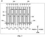
- channel R through which vapor phase refrigerant flows may be configured as illustrated in FIG 7 .
- fourth channel R4 and sixth channel R6 are configured to communicate with each other only on the upper side of heat transfer plate 21.
- second channel R2 and fourth channel R4 are configured to communicate with each other on the upper side and lower side of heat transfer plate 21.
- sixth, eighth and tenth channels R6, R8 and R10 are configured to communicate with each other on the upper side and lower side of heat transfer plate 21.
- the vapor phase refrigerant flowed out from gas-liquid separator 13 flows through channel R of first heat exchanging part 20a as indicated with the solid line arrow illustrated in FIG 7 . More specifically, the vapor phase refrigerant flows into second channel R2 from the lower side through first connection pipe 23a, and flows through second and fourth channels R2 and R4 from the lower side toward the upper side.
- the vapor phase refrigerant flowed through fourth channel R4 flows through channel R of second heat exchanging part 20b as indicated with the solid line arrow illustrated in FIG 7 . More specifically, the vapor phase refrigerant flowed through fourth channel R4 flows into sixth channel R6 from the upper side, flows through sixth, eighth and tenth channels R6, R8 and R10 from the upper side toward the lower side, and flows out from the lower side of tenth channel through fourth connection pipe 23d.
- the refrigeration circuit and the refrigeration device of the present disclosure are widely applicable to ultra-low-temperature freezers and refrigerators.
Landscapes
- Engineering & Computer Science (AREA)
- Physics & Mathematics (AREA)
- Thermal Sciences (AREA)
- Mechanical Engineering (AREA)
- General Engineering & Computer Science (AREA)
- Chemical & Material Sciences (AREA)
- Analytical Chemistry (AREA)
- Power Engineering (AREA)
- Heat-Exchange Devices With Radiators And Conduit Assemblies (AREA)
Abstract
Description
- The present disclosure relates to a refrigeration circuit and a refrigeration device.
- A refrigeration circuit includes a heat exchanger for cooling circulating refrigerant so as to obtain the temperature of the refrigerant required at an evaporator. For example,
PTL 1 discloses a refrigeration circuit including a flow divider for separating gas and liquid, and a double tube heat exchanger for exchanging heat between the vapor phase refrigerant flowed out from the flow divider, and the liquid phase refrigerant flowed out from the flow divider and the refrigerant returning to the compressor from the evaporator. -
PTL 1
Japanese Patent Publication No. 5128424 - In refrigeration circuits, lower temperatures may be required depending on the object to be cooled. This requires enhancement in heat exchanging efficiency, but the increase in size of the heat exchanger and in number of heat exchangers may cause a problem in terms of the mounting space of the heat exchanger.
- To solve the known problems of the related art, an object of the present disclosure is to reduce the size of a heat exchanger and improve the heat exchanging efficiency in a refrigeration circuit and a refrigeration device.
- To achieve the above-mentioned object, a refrigeration circuit in the present disclosure includes: a gas-liquid separator into which a gas-liquid two-phase refrigerant flowed out from a condenser flows, the gas-liquid separator being configured to separate the gas-liquid two-phase refrigerant into a vapor phase refrigerant and a liquid phase refrigerant; and a plate heat exchanger including a first heat exchanging part and a second heat exchanging part, the first heat exchanging part being a part where the vapor phase refrigerant flowed out from the gas-liquid separator and the liquid phase refrigerant flowed out from the gas-liquid separator exchange heat, the second heat exchanging part being a part where the vapor phase refrigerant flowed out from the first heat exchanging part and a returning refrigerant flowed out from an evaporator exchange heat.
- In addition, to achieve the above-mentioned object, a refrigeration device in the present disclosure includes the above-described refrigeration circuit.
- With the refrigeration circuit and the refrigeration device according to embodiments of the present disclosure, it is possible to reduce the size of the heat exchanger and improve the heat exchanging efficiency.
-
-
FIG 1 is a schematic view of a refrigeration circuit in an embodiment of the present disclosure; -
FIG 2 is a front view of a plate heat exchanger illustrated inFIG 1 ; -
FIG 3 is a schematic view illustrating a flow of a refrigerant in the plate heat exchanger; -
FIG 4 is a partially enlarged sectional view of the plate heat exchanger; -
FIG 5 is a schematic view illustrating a flow of a refrigerant in the plate heat exchanger; -
FIG 6 is a schematic view of a refrigeration circuit of a modification of the present disclosure; and -
FIG 7 is a schematic view illustrating a flow of a refrigerant in a plate heat exchanger of a modification of the present disclosure. -
Refrigeration circuit 1 according to an embodiment of the present disclosure is described below with reference to the drawings.Refrigeration circuit 1 is used for a refrigeration device such as an ultra-low-temperature freezer. As illustrated inFIG 1 ,refrigeration circuit 1 includescompressor 10,condenser 11,dryer 12, gas-liquid separator 13,first decompressor 14,plate heat exchanger 20,second decompressor 15, doubletube heat exchanger 16, andevaporator 17. - A gas-liquid two-phase refrigerant, which is a mixture of a vapor phase refrigerant and a liquid phase refrigerant, enters gas-
liquid separator 13, and gas-liquid separator 13 separates the gas-liquid two-phase refrigerant into a vapor phase refrigerant and a liquid phase refrigerant. The vapor phase refrigerant flows out from the upper part of gas-liquid separator 13. The liquid phase refrigerant flows out from the lower part of gas-liquid separator 13.First decompressor 14 is a capillary tube, for example. -
Plate heat exchanger 20 includes firstheat exchanging part 20a and secondheat exchanging part 20b. Firstheat exchanging part 20a exchanges heat between the vapor phase refrigerant flowed out from gas-liquid separator 13, and a mixed refrigerant of a returning refrigerant and the liquid phase refrigerant flowed out from gas-liquid separator 13. The returning refrigerant is a refrigerant flowing out fromevaporator 17 and returning tocompressor 10. - Second
heat exchanging part 20b exchanges heat between the vapor phase refrigerant flowed out from firstheat exchanging part 20a and the returning refrigerant flowed out fromevaporator 17. Details ofplate heat exchanger 20 are described later. - The inner pipe of double
tube heat exchanger 16 issecond decompressor 15.Second decompressor 15 is a capillary tube, for example. The returning refrigerant flowed out fromevaporator 17 flows throughouter pipe 16a of doubletube heat exchanger 16. That is, in doubletube heat exchanger 16, the returning refrigerant and the refrigerant flowing throughsecond decompressor 15 exchange heat. - The above-described devices are connected by
pipe 18 such that the refrigerant ejected fromcompressor 10 returns tocompressor 10 again. - The refrigerant illustrated in
FIG 1 circulates in the arrow direction. More specifically, the refrigerant flows throughcompressor 10,condenser 11 anddryer 12 in this order, and then flows into gas-liquid separator 13. The refrigerant is separated into a vapor phase refrigerant and a liquid phase refrigerant at gas-liquid separator 13. - The vapor phase refrigerant flowed out from gas-
liquid separator 13 flows through firstheat exchanging part 20a, secondheat exchanging part 20b,second decompressor 15 andevaporator 17 in this order. Further, the returning refrigerant flowed out fromevaporator 17 flows throughouter pipe 16a of doubletube heat exchanger 16 and secondheat exchanging part 20b in this order. The returning refrigerant flowed out from secondheat exchanging part 20b flows out from gas-liquid separator 13, merges atconfluence part 18a with the liquid phase refrigerant flowed throughfirst decompressor 14, and returns tocompressor 10 through firstheat exchanging part 20a. - Note that the gas-liquid two-phase refrigerant is a mixture of a vapor phase refrigerant and a liquid phase refrigerant. More specifically, the gas-liquid two-phase refrigerant is a mixture of one or more refrigerants respectively selected from among the liquid phase refrigerant listed in the group A and the vapor phase refrigerant listed in the group B shown in Table 1. Note that the liquid phase refrigerant is a refrigerant with a boiling point of -55°C or higher, and liquefies before flowing into gas-
liquid separator 13. In addition, the vapor phase refrigerant is a refrigerant with a boiling point lower than -55°C.[Table 1] Refrigerant No. Name Boiling Point (°C) Group A R245fa 1,1,1,3,3-Pentafluoropropane 15.3 R600 Normal butane -0.55 R600a Isobutane -11.7 R1233zd trans-1-chloro-3,3,3-trifluoropropene 19.0 R1224yd(Z) (Z)-1-Chloro-2,3,3,3,-tetrafluoropropene 15.0 R1336mzz(Z) 1,1,1,4,4,4,-hexafluoro-2-butane 33.0 R1234yf 2,3,3,3-tetrafluoro-1-propene -29.0 R1234ze(E) trans-1,3,3,3-tetrafluoroprop-1-ene -19.0 R290 Propane -42.1 R32 Difluoroethane -51.7 R-1270 Propylene -47.7 R125 Pentafluoroethane -48.1 Group B R23 Trifluoromethane -82.1 R508A Refrigerant made by mixing trifluoromethane (R23) and hexafluoroethane (R116) at 39wt% and 61wt%. -85.7 R508B Refrigerant made by mixing trifluoromethane (R23) and hexafluoroethane (R116) at 46wt% and 54wt%. -86.9 R170 Ethane -89.0 R744 Carbon dioxide -78.4 R14 Tetrafluoromethane -128.1 R-1150 Ethylene -104.0 Kr Krypton -152.3 R50 Methane -161.5 R740 Argon -185.8 - Next, details of
plate heat exchanger 20 are described with reference toFIGS. 2 to 5 . Note that for convenience of the description below, the upper side and lower side inFIG 2 are the upper side and lower side ofplate heat exchanger 20. Likewise, the left side and right side are the left side and right side ofplate heat exchanger 20, and the near side and depth side in the drawing are the front side and rear side ofplate heat exchanger 20. -
Plate heat exchanger 20 is a brazed plate heat exchanger.Plate heat exchanger 20 includes a plurality of heat transfer plates 21 andcover plates 22. Twelve heat transfer plates 21 are provided in the present embodiment. Heat transfer plate 21 andcover plate 22 are examples of "plate". Heat transfer plate 21 andcover plate 22 are plate members with a rectangular shape in front view. - The plurality of heat transfer plates 21 is disposed side by side along the front-rear direction with their plate surfaces parallel to each other and with a predetermined distance therebetween (
FIG. 3 ). In this manner, channel R through which refrigerant flows is formed between heat transfer plates 21 adjacent to each other. More specifically, first channel R1 to eleventh channel R11 are formed in this order from the front side to the rear side. - In addition, second channel R2 and fourth channel R4 are formed so as to be communicated with each other (
FIG. 4 ). Further, second and fourth channels R2 and 4 are formed so as not to communicate with adjacent channel R. More specifically, in thirdheat transfer plate 21c making up second channel R2, protruding part 21c1 protruding in a columnar shape toward adjacent fourthheat transfer plate 21d making up fourth channel R4 and through hole 21c2 formed at the protruding end of protruding part 21c1 are formed. - Through hole 21c2 is communicated with through hole 21d1 formed in fourth
heat transfer plate 21d. In addition, the peripheries of through holes 21c2 and 21d1 are in contact with each other and welded. In this manner, second channel R2 and fourth channel R4 communicate with each other, and do not communicate with third channel R3 located between second and fourth channels R2 and R4. - In addition, with similar configurations, channels R adjacent to each other in fourth, sixth, eighth, tenth channels R4, R6, R8 and R10 are configured to communicate with each other. Further, with similar configurations, channels R adjacent to each other in first, third and fifth channels R1, R3 and R5 are configured to communicate with each other. Further, with similar configurations, channels R adjacent to each other in seventh, ninth and eleventh channels R7, R9 and R11 are configured to communicate with each other. Note that the above-described channels R adjacent to each other are configured to communicate with each other on the upper side and lower side of heat transfer plate 21, except between sixth channel R6 and eighth channel R8. The part between sixth channel R6 and eighth channel R8 are configured to communicate on the upper side of heat transfer plate 21.
-
Cover plate 22 is disposed at the front ends and rear ends of the plurality of heat transfer plates 21 disposed side by side. Eachcover plate 22 is disposed such that the plate surfaces of eachcover plate 22 and opposite heat transfer plate 21 are in contact with each other. - In addition,
first connection pipe 23a,second connection pipe 23b andthird connection pipe 23c are disposed at the plate surface offirst cover plate 22a. First andsecond connection pipes first cover plate 22a.Third connection pipe 23c is disposed on the upper side ofsecond connection pipe 23b.First connection pipe 23a is an example of "vapor phase refrigerant inflow part".Second connection pipe 23b is an example of "liquid phase refrigerant inflow part".Third connection pipe 23c is an example of "liquid phase refrigerant outflow part". - Further,
fourth connection pipe 23d,fifth connection pipe 23e andsixth connection pipe 23f are disposed at the plate surface ofsecond cover plate 22b. Fourth andfifth connection pipes second cover plate 22b.Sixth connection pipe 23f is disposed on the upper side offifth connection pipe 23e.Fourth connection pipe 23d is an example of "vapor phase refrigerant outflow part".Fifth connection pipe 23e is an example of "returning refrigerant inflow part".Sixth connection pipe 23f is an example of "returning refrigerant outflow part". - The first end of
first connection pipe 23a is connected topipe 18 connected to the upper part of gas-liquid separator 13. The second end offirst connection pipe 23 a is open to second channel R2. The first end ofsecond connection pipe 23b is connected to the first end ofsixth connection pipe 23f throughpipe 18. The second end ofsecond connection pipe 23b is open to first channel R1. - The first end of
third connection pipe 23c is connected topipe 18 connected tocompressor 10. The second end ofthird connection pipe 23c is open to first channel R1. The first end offourth connection pipe 23d is connected topipe 18 connected tosecond decompressor 15. The second end offourth connection pipe 23d is open at tenth channel R10. - The first end of
fifth connection pipe 23e is connected topipe 18 connected toouter pipe 16a of doubletube heat exchanger 16. The second end offifth connection pipe 23e is open to eleventh channel R11. The first end ofsixth connection pipe 23f is connected to the first end ofsecond connection pipe 23b as described above. The second end ofsixth connection pipe 23f is open at eleventh channel R11. - First
heat exchanging part 20a is composed offirst cover plate 22a, first to sixthheat transfer plates 21a to 21f, and first tothird connection pipes 23a to 23c. - Second
heat exchanging part 20b is composed ofsecond cover plate 22b, seventh to twelfthheat transfer plates 21g to 21l, and fourth tosixth connection pipes 23d to 23f. Firstheat exchanging part 20a and secondheat exchanging part 20b are integrally formed. - Next, heat exchange at first
heat exchanging part 20a is described. - The vapor phase refrigerant flowed out from gas-
liquid separator 13 flows through channel R of firstheat exchanging part 20a as indicated with the solid line arrow illustrated inFIG 3 . More specifically, the vapor phase refrigerant flows into second channel R2 from the lower side throughfirst connection pipe 23a, flows through second, fourth and sixth channels R2, R4 and R6 from the lower side toward the upper side, and flows out from the upper side of sixth channel R6 to eighth channel R8. - On the other hand, the refrigerant (hereinafter referred to as merged refrigerant) composed of the returning refrigerant flowed out from
sixth connection pipe 23f and the liquid phase refrigerant flowed out from gas-liquid separator 13 that are merged with each other atconfluence part 18a flows through channel R of firstheat exchanging part 20a as indicated with the broken line arrow illustrated inFIG 5 . More specifically, the merged refrigerant flows into first channel R1 from the lower side throughsecond connection pipe 23b, flows through first, third and fifth channels R1, R3 and R5 from the lower side toward the upper side, and flows out from the upper side of first channel R1 throughthird connection pipe 23c. - In this manner, refrigerants with temperatures different from each other flow in channels R adjacent to each other with second to sixth
heat transfer plates 23b to 21f therebetween. In this manner, the vapor phase refrigerant and the merged refrigerant exchange heat through second to sixthheat transfer plates 23b to 21f. - Next, heat exchange at second
heat exchanging part 20b is described. - The vapor phase refrigerant flowed into eighth channel R8 from the upper side flows through channel R of second
heat exchanging part 20b as indicated with the solid line arrow illustrated inFIG 3 . More specifically, the vapor phase refrigerant flowed into eighth channel R8 from the upper side flows through eighth and tenth channels R8 and R10 from the upper side toward the lower side, and flows out from the lower side of tenth channel R10 throughfourth connection pipe 23d. - On the other hand, the returning refrigerant flowed out from
outer pipe 16a of doubletube heat exchanger 16 flows through channel R of secondheat exchanging part 20b as indicated with the broken line arrow illustrated inFIG 5 . More specifically, the returning refrigerant flows into eleventh channel R11 from the lower side throughfifth connection pipe 23e, flows through seventh, ninth and eleventh channels R7, R9 and R11 from the lower side toward the upper side, and flows out from the upper side of eleventh channel R11 throughsixth connection pipe 23f. - In this manner, refrigerants with temperatures different from each other flow in channels R adjacent to each other with seventh to eleventh
heat transfer plates 21g to 21k therebetween. In this manner, the vapor phase refrigerant and the returning refrigerant exchange heat through seventh to eleventhheat transfer plates 21g to 21k. - According to the present embodiment,
refrigeration circuit 1 includes gas-liquid separator 13 into which the gas-liquid two-phase refrigerant flowed out fromcondenser 11 flows, andplate heat exchanger 20 including firstheat exchanging part 20a where the vapor phase refrigerant flowed out from gas-liquid separator 13 and the liquid phase refrigerant flowed out from gas-liquid separator 13 exchange heat, and secondheat exchanging part 20b where the vapor phase refrigerant flowed out from firstheat exchanging part 20a and the returning refrigerant flowed out fromevaporator 17 exchange heat. Gas-liquid separator 13 separates the gas-liquid two-phase refrigerant into a vapor phase refrigerant and a liquid phase refrigerant - In this manner,
refrigeration circuit 1 performs two-stage heat exchange by using oneplate heat exchanger 20 for the refrigerant flowing fromcondenser 11 towardevaporator 17. Thus, the size of the heat exchanger can be reduced, and the low temperature required atevaporator 17 can be obtained in such a manner that the refrigerant flowing towardevaporator 17 efficiently exchanges heat. - In addition, in first
heat exchanging part 20a, the heat is exchanged between the vapor phase refrigerant flowed out from gas-liquid separator 13, and the mixed refrigerant of the liquid phase refrigerant flowed out from gas-liquid separator 13 and the returning refrigerant flowed out from secondheat exchanging part 20b. - In this manner, at first
heat exchanging part 20a, the heat can be exchanged by using the refrigerant of the mixture of the liquid phase refrigerant and the returning refrigerant. - In addition, in
plate heat exchanger 20, the plurality ofcover plates 22 and the plurality of heat transfer plates 21 are disposed side by side such that their plate surfaces face each other. At the plate surface offirst cover plate 22a disposed at the first end ofplate heat exchanger 20,first connection pipe 23a into which the vapor phase refrigerant flows,second connection pipe 23b into which the liquid phase refrigerant flows, and thethird connection pipe 23c from which the liquid phase refrigerant flows out are disposed. At the plate surface ofsecond cover plate 22b disposed at the second end ofplate heat exchanger 20,fourth connection pipe 23d from which the vapor phase refrigerant flows out,fifth connection pipe 23e into which the returning refrigerant flows, andsixth connection pipe 23f from which the returning refrigerant flows out are disposed. - This increases the ease of the routing of
pipe 18. - In addition,
refrigeration circuit 1 further includes doubletube heat exchanger 16 including the inner pipe into which the vapor phase refrigerant flowed out from secondheat exchanging part 20b flows andouter pipe 16a through which the returning refrigerant that flows into secondheat exchanging part 20b flows. - In this manner, with double
tube heat exchanger 16, the temperature of the refrigerant supplied toevaporator 17 can be further reduced. Moreover, a countercurrent heat exchanger can be made up of the entirety of the heat exchanger system composed of firstheat exchanging part 20a, secondheat exchanging part 20b and doubletube heat exchanger 16. Thus, the required ultra-low temperature can be obtained by efficiently exchanging heat while making the entirety of the heat exchanger system compact. - The above description of one or more forms of refrigeration circuits is based on the embodiment, but this disclosure is not limited to this embodiment. As long as the main purpose of this disclosure is not departed from, various variations that one skilled in the art can conceive of are applied to this embodiment, and embodiments constructed by combining components in different embodiments may also be included within the scope of one or more embodiments.
- Instead of the above-described configuration in which the merged refrigerant and the vapor phase refrigerant flowed out from gas-
liquid separator 13 exchange heat in firstheat exchanging part 20a, pipe 118 may be configured such that the vapor phase refrigerant flowed out from gas-liquid separator 13 and the liquid phase refrigerant flowed out from gas-liquid separator 13 exchange heat. In this case, as illustrated inFIG 6 , the liquid phase refrigerant flowed out from gas-liquid separator 13 flows intosecond connection pipe 23b. Further, the liquid phase refrigerant flowed out fromthird connection pipe 23c merges atconfluence part 118a with the returning refrigerant flowed out from secondheat exchanging part 20b, and returns tocompressor 10 as the gas-liquid two-phase refrigerant. - In addition, heat transfer plate 21 may be formed such that the plate surface has a wave shape. In this manner, the flow of the refrigerant can be more easily made turbulent in comparison with the case where the plate surface has a planar shape, and thus the heat exchange efficiency can be improved.
- In addition,
refrigeration circuit 1 may not include doubletube heat exchanger 16. In this case, the refrigerant flowed out from secondheat exchanging part 20b flows throughsecond decompressor 15 andevaporator 17 in this order. Further, the returning refrigerant flowed out fromevaporator 17 flows into secondheat exchanging part 20b. - In addition, in
plate heat exchanger 20, channel R through which vapor phase refrigerant flows may be configured as illustrated inFIG 7 . More specifically, fourth channel R4 and sixth channel R6 are configured to communicate with each other only on the upper side of heat transfer plate 21. In addition, second channel R2 and fourth channel R4 are configured to communicate with each other on the upper side and lower side of heat transfer plate 21. Further, sixth, eighth and tenth channels R6, R8 and R10 are configured to communicate with each other on the upper side and lower side of heat transfer plate 21. - In this manner, the vapor phase refrigerant flowed out from gas-
liquid separator 13 flows through channel R of firstheat exchanging part 20a as indicated with the solid line arrow illustrated inFIG 7 . More specifically, the vapor phase refrigerant flows into second channel R2 from the lower side throughfirst connection pipe 23a, and flows through second and fourth channels R2 and R4 from the lower side toward the upper side. - Further, the vapor phase refrigerant flowed through fourth channel R4 flows through channel R of second
heat exchanging part 20b as indicated with the solid line arrow illustrated inFIG 7 . More specifically, the vapor phase refrigerant flowed through fourth channel R4 flows into sixth channel R6 from the upper side, flows through sixth, eighth and tenth channels R6, R8 and R10 from the upper side toward the lower side, and flows out from the lower side of tenth channel throughfourth connection pipe 23d. - This application is entitled to and claims the benefit of
Japanese Patent Application No. 2021-004787 filed on January 15, 2021 - The refrigeration circuit and the refrigeration device of the present disclosure are widely applicable to ultra-low-temperature freezers and refrigerators.
-
- 1
- Refrigeration circuit
- 10
- Compressor
- 11
- Condenser
- 12
- Dryer
- 13
- Gas-liquid separator
- 16
- Double tube heat exchanger
- 17
- Evaporator
- 20
- Plate heat exchanger
- 20a
- First heat exchanging part
- 20b
- Second heat exchanging part
- 21
- Heat transfer plate (Plate)
- 22
- Cover plate (Plate)
- 23a
- First connection pipe (Vapor phase refrigerant inflow part)
- 23b
- Second connection pipe (Liquid phase refrigerant inflow part)
- 23c
- Third connection pipe (Liquid phase refrigerant outflow part)
- 23d
- Fourth connection pipe (Vapor phase refrigerant outflow part)
- 23e
- Fifth connection pipe (Returning refrigerant inflow part)
- 23f
- Sixth connection pipe (Returning refrigerant outflow part)
Claims (5)
- A refrigeration circuit comprising:a gas-liquid separator into which a gas-liquid two-phase refrigerant flowed out from a condenser flows, the gas-liquid separator being configured to separate the gas-liquid two-phase refrigerant into a vapor phase refrigerant and a liquid phase refrigerant; anda plate heat exchanger including a first heat exchanging part and a second heat exchanging part, the first heat exchanging part being a part where the vapor phase refrigerant flowed out from the gas-liquid separator and the liquid phase refrigerant flowed out from the gas-liquid separator exchange heat, the second heat exchanging part being a part where the vapor phase refrigerant flowed out from the first heat exchanging part and a returning refrigerant flowed out from an evaporator exchange heat.
- The refrigeration circuit according to claim 1, wherein in the first heat exchanging part, the vapor phase refrigerant flowed out from the gas-liquid separator, and a refrigerant that is a mixture of the liquid phase refrigerant flowed out from the gas-liquid separator and the returning refrigerant flowed out from the second heat exchanging part exchange heat.
- The refrigeration circuit according to claim 1 or 2,wherein in the plate heat exchanger, a plurality of plates is disposed side by side with plate surfaces of the plurality of plates facing each other;wherein at a plate surface of a plate disposed at a first end of the plate heat exchanger, a vapor phase refrigerant inflow part where the vapor phase refrigerant flows in, a liquid phase refrigerant inflow part where the liquid phase refrigerant flows in, and a liquid phase refrigerant outflow part where the liquid phase refrigerant flows out are disposed; andwherein at a plate surface of a plate disposed at a second end of the plate heat exchanger, a vapor phase refrigerant outflow part where the vapor phase refrigerant flows out, a returning refrigerant inflow part where the returning refrigerant flows in, and a returning refrigerant outflow part where the returning refrigerant flows out are disposed.
- The refrigeration circuit according to any one of claims 1 to 3, further comprising a double tube heat exchanger including an inner pipe through which the vapor phase refrigerant flowed out from the second heat exchanging part flows, and an outer pipe through which the returning refrigerant that flows into the second heat exchanging part flows.
- A refrigeration device comprising the refrigeration circuit according to any one of claims 1 to 4.
Applications Claiming Priority (2)
| Application Number | Priority Date | Filing Date | Title |
|---|---|---|---|
| JP2021004787 | 2021-01-15 | ||
| PCT/JP2021/045834 WO2022153760A1 (en) | 2021-01-15 | 2021-12-13 | Refrigeration circuit and refrigeration device |
Publications (2)
| Publication Number | Publication Date |
|---|---|
| EP4184086A1 true EP4184086A1 (en) | 2023-05-24 |
| EP4184086A4 EP4184086A4 (en) | 2024-01-10 |
Family
ID=82447180
Family Applications (1)
| Application Number | Title | Priority Date | Filing Date |
|---|---|---|---|
| EP21918131.0A Pending EP4184086A4 (en) | 2021-01-15 | 2021-12-13 | REFRIGERANT CIRCUIT AND COOLING DEVICE |
Country Status (5)
| Country | Link |
|---|---|
| US (1) | US12429264B2 (en) |
| EP (1) | EP4184086A4 (en) |
| JP (1) | JP7410335B2 (en) |
| CN (1) | CN116075674A (en) |
| WO (1) | WO2022153760A1 (en) |
Family Cites Families (18)
| Publication number | Priority date | Publication date | Assignee | Title |
|---|---|---|---|---|
| US1680145A (en) * | 1924-01-30 | 1928-08-07 | Forssblad Nils Richard | Heat exchanger |
| US5617739A (en) | 1995-03-29 | 1997-04-08 | Mmr Technologies, Inc. | Self-cleaning low-temperature refrigeration system |
| US5724832A (en) * | 1995-03-29 | 1998-03-10 | Mmr Technologies, Inc. | Self-cleaning cryogenic refrigeration system |
| US5791160A (en) * | 1997-07-24 | 1998-08-11 | Air Products And Chemicals, Inc. | Method and apparatus for regulatory control of production and temperature in a mixed refrigerant liquefied natural gas facility |
| US6065305A (en) * | 1998-12-30 | 2000-05-23 | Praxair Technology, Inc. | Multicomponent refrigerant cooling with internal recycle |
| JP2002048421A (en) * | 2000-08-01 | 2002-02-15 | Matsushita Electric Ind Co Ltd | Refrigeration cycle device |
| US7478540B2 (en) * | 2001-10-26 | 2009-01-20 | Brooks Automation, Inc. | Methods of freezeout prevention and temperature control for very low temperature mixed refrigerant systems |
| JP2005009851A (en) * | 2003-05-27 | 2005-01-13 | Calsonic Kansei Corp | Air conditioning device |
| US7089760B2 (en) | 2003-05-27 | 2006-08-15 | Calsonic Kansei Corporation | Air-conditioner |
| JP5128424B2 (en) | 2008-09-10 | 2013-01-23 | パナソニックヘルスケア株式会社 | Refrigeration equipment |
| US9441877B2 (en) * | 2010-03-17 | 2016-09-13 | Chart Inc. | Integrated pre-cooled mixed refrigerant system and method |
| WO2012094652A2 (en) * | 2011-01-06 | 2012-07-12 | Clean Rolling Power, LLC | Multichamber heat exchanger |
| CN202267276U (en) * | 2011-09-30 | 2012-06-06 | 海信容声(广东)冷柜有限公司 | Showcase |
| US11408673B2 (en) * | 2013-03-15 | 2022-08-09 | Chart Energy & Chemicals, Inc. | Mixed refrigerant system and method |
| ES3053318T3 (en) * | 2014-12-12 | 2026-01-21 | Siemens Energy Inc | System and method for liquefaction of natural gas |
| AR105277A1 (en) * | 2015-07-08 | 2017-09-20 | Chart Energy & Chemicals Inc | MIXED REFRIGERATION SYSTEM AND METHOD |
| JP7500166B2 (en) | 2019-06-26 | 2024-06-17 | 三菱重工業株式会社 | Damage risk assessment method, system maintenance management method, and risk assessment device |
| US12025387B2 (en) * | 2019-08-06 | 2024-07-02 | Meggitt Aerospace Limited | Turning vanes and heat exchangers and methods of making the same |
-
2021
- 2021-12-13 WO PCT/JP2021/045834 patent/WO2022153760A1/en not_active Ceased
- 2021-12-13 CN CN202180056009.2A patent/CN116075674A/en active Pending
- 2021-12-13 EP EP21918131.0A patent/EP4184086A4/en active Pending
- 2021-12-13 JP JP2022575147A patent/JP7410335B2/en active Active
-
2023
- 2023-02-13 US US18/108,973 patent/US12429264B2/en active Active
Also Published As
| Publication number | Publication date |
|---|---|
| JPWO2022153760A1 (en) | 2022-07-21 |
| US12429264B2 (en) | 2025-09-30 |
| EP4184086A4 (en) | 2024-01-10 |
| US20230184472A1 (en) | 2023-06-15 |
| CN116075674A (en) | 2023-05-05 |
| JP7410335B2 (en) | 2024-01-09 |
| WO2022153760A1 (en) | 2022-07-21 |
Similar Documents
| Publication | Publication Date | Title |
|---|---|---|
| JP6022156B2 (en) | Vehicle capacitors | |
| CN105074375B (en) | Cascade type heat exchanger | |
| JP5960955B2 (en) | Vehicle capacitors | |
| JP6041424B2 (en) | Vehicle capacitors | |
| EP2592366A2 (en) | Non-azeotropic mixed refrigerant cycle and refrigerator equipped therewith | |
| KR101755456B1 (en) | Heat exchanger | |
| JP5758991B2 (en) | Heat exchanger and refrigeration cycle apparatus including the same | |
| JP6042026B2 (en) | Refrigeration cycle equipment | |
| US20140096935A1 (en) | Heat Exchanger for Vehicle | |
| US11656033B2 (en) | Combined core microchannel heat exchanger | |
| US6793010B1 (en) | Heat exchanger having non-perpendicularly aligned heat transfer elements | |
| US12000628B2 (en) | Magnetic refrigeration module | |
| EP4411300A1 (en) | Heat exchanger | |
| WO2018029784A1 (en) | Heat exchanger and refrigeration cycle device provided with heat exchanger | |
| CN107003081A (en) | Heat exchanger and the refrigerating circulatory device with the heat exchanger | |
| US12429264B2 (en) | Refrigeration circuit and refrigeration device | |
| US6652769B1 (en) | Refrigerant composition and refrigerating circuit employing the same | |
| JP7292513B2 (en) | Heat exchanger and air conditioner using the same | |
| KR20120061671A (en) | Condenser for vehicle | |
| JP2020118369A (en) | Plate fin stacked heat exchanger and refrigeration system using the same | |
| JP2017138053A (en) | Battery cooling device | |
| JP2002174495A (en) | Heat exchanger | |
| WO2016039114A1 (en) | Turbo refrigeration machine | |
| JP2008241195A (en) | Refrigeration equipment | |
| JP6827179B2 (en) | Heat exchanger and refrigeration system using it |
Legal Events
| Date | Code | Title | Description |
|---|---|---|---|
| STAA | Information on the status of an ep patent application or granted ep patent |
Free format text: STATUS: THE INTERNATIONAL PUBLICATION HAS BEEN MADE |
|
| PUAI | Public reference made under article 153(3) epc to a published international application that has entered the european phase |
Free format text: ORIGINAL CODE: 0009012 |
|
| STAA | Information on the status of an ep patent application or granted ep patent |
Free format text: STATUS: REQUEST FOR EXAMINATION WAS MADE |
|
| 17P | Request for examination filed |
Effective date: 20230215 |
|
| AK | Designated contracting states |
Kind code of ref document: A1 Designated state(s): AL AT BE BG CH CY CZ DE DK EE ES FI FR GB GR HR HU IE IS IT LI LT LU LV MC MK MT NL NO PL PT RO RS SE SI SK SM TR |
|
| A4 | Supplementary search report drawn up and despatched |
Effective date: 20231213 |
|
| RIC1 | Information provided on ipc code assigned before grant |
Ipc: F25B 40/00 20060101ALI20231207BHEP Ipc: F25B 39/02 20060101ALI20231207BHEP Ipc: F25B 5/02 20060101ALI20231207BHEP Ipc: F25B 1/00 20060101ALI20231207BHEP Ipc: F28D 9/00 20060101ALI20231207BHEP Ipc: F28D 7/10 20060101ALI20231207BHEP Ipc: F25B 43/00 20060101AFI20231207BHEP |
|
| DAV | Request for validation of the european patent (deleted) | ||
| DAX | Request for extension of the european patent (deleted) | ||
| STAA | Information on the status of an ep patent application or granted ep patent |
Free format text: STATUS: EXAMINATION IS IN PROGRESS |
|
| 17Q | First examination report despatched |
Effective date: 20241010 |
|
| RAP3 | Party data changed (applicant data changed or rights of an application transferred) |
Owner name: PHC HOLDINGS CORPORATION |
|
| GRAP | Despatch of communication of intention to grant a patent |
Free format text: ORIGINAL CODE: EPIDOSNIGR1 |
|
| STAA | Information on the status of an ep patent application or granted ep patent |
Free format text: STATUS: GRANT OF PATENT IS INTENDED |