EP4184065A1 - Indoor unit - Google Patents
Indoor unit Download PDFInfo
- Publication number
- EP4184065A1 EP4184065A1 EP22207446.0A EP22207446A EP4184065A1 EP 4184065 A1 EP4184065 A1 EP 4184065A1 EP 22207446 A EP22207446 A EP 22207446A EP 4184065 A1 EP4184065 A1 EP 4184065A1
- Authority
- EP
- European Patent Office
- Prior art keywords
- casing
- arm
- holder
- panel
- indoor unit
- Prior art date
- Legal status (The legal status is an assumption and is not a legal conclusion. Google has not performed a legal analysis and makes no representation as to the accuracy of the status listed.)
- Granted
Links
Images



Classifications
-
- F—MECHANICAL ENGINEERING; LIGHTING; HEATING; WEAPONS; BLASTING
- F24—HEATING; RANGES; VENTILATING
- F24F—AIR-CONDITIONING; AIR-HUMIDIFICATION; VENTILATION; USE OF AIR CURRENTS FOR SCREENING
- F24F1/00—Room units for air-conditioning, e.g. separate or self-contained units or units receiving primary air from a central station
- F24F1/0007—Indoor units, e.g. fan coil units
-
- F—MECHANICAL ENGINEERING; LIGHTING; HEATING; WEAPONS; BLASTING
- F24—HEATING; RANGES; VENTILATING
- F24F—AIR-CONDITIONING; AIR-HUMIDIFICATION; VENTILATION; USE OF AIR CURRENTS FOR SCREENING
- F24F13/00—Details common to, or for air-conditioning, air-humidification, ventilation or use of air currents for screening
- F24F13/20—Casings or covers
-
- F—MECHANICAL ENGINEERING; LIGHTING; HEATING; WEAPONS; BLASTING
- F24—HEATING; RANGES; VENTILATING
- F24F—AIR-CONDITIONING; AIR-HUMIDIFICATION; VENTILATION; USE OF AIR CURRENTS FOR SCREENING
- F24F1/00—Room units for air-conditioning, e.g. separate or self-contained units or units receiving primary air from a central station
- F24F1/0007—Indoor units, e.g. fan coil units
- F24F1/0043—Indoor units, e.g. fan coil units characterised by mounting arrangements
- F24F1/0057—Indoor units, e.g. fan coil units characterised by mounting arrangements mounted in or on a wall
Definitions
- the present disclosure relates to an indoor unit.
- Japanese Unexamined Patent Application, First Publication No. H7-260193 discloses a panel attachment structure for attaching a panel (inlet panel) to an opening portion of a casing of an indoor unit in a manner of being able to be opened and closed.
- a second arm having a rotation center positioned on an outer side of the casing slides with respect to a first arm inside the casing so that the inlet panel provided in the second arm is opened and closed.
- cutout portions notches
- exposure of cutout portions (notches) required for movement of arms during opening and closing of an inlet panel to the outside is avoided so that a good appearance of an indoor unit is not impaired when the inlet panel is closed.
- the present disclosure has been made in order to resolve the foregoing problems, and an object thereof is to provide an indoor unit in which arms are easily attached and detached with respect to a casing and a good appearance is not impaired when an inlet panel is closed.
- an indoor unit includes: a casing having a front surface and holder accommodation portions opening on the front surface and recessed so as to slope upward approaching toward a back side of the casing; arm holders which are inserted into the holder accommodation portions from a front side of the casing and which are installed inside of the holder accommodation portions so as to be detachable therefrom; arms which are inserted into the holder accommodation portions from the front side of the casing and each of which a first end is held by the arm holder so that the arm is allowed to turn around an axis extending in a longitudinal direction of the casing; and an inlet panel to which a second end of each of the arms is fixed.
- the range of movement of the arms around the axis is set between a closed position where the inlet panel is disposed in a manner of overlapping the front surface of the casing and openings of the holder accommodation portions are closed by the inlet panel, and an open position where the inlet panel is disposed forward and upward from the front surface of the casing and the front surface of the casing is exposed.
- An indoor unit is an apparatus which is provided indoors and performs indoor-air conditioning through heat exchange between a refrigerant dealing with an outdoor unit provided outdoors and indoor air.
- An air conditioning apparatus is constituted of an indoor unit and an outdoor unit.
- an indoor unit 100 includes a casing 1, a fan 2, a heat exchanger 3, a Filter part 4, a control unit 5, an arm holder 6, a bolt 7, an arm 8 and an inlet panel 9.
- the casing 1 is constituted of a plurality of panels and installed on an indoor wall surface W.
- the casing 1 forms an outer shell of the indoor unit 100.
- the casing 1 accommodates various equipment and defines a space for circulating indoor air on an inner side.
- the casing 1 has a back surface panel 10, a bottom panel 20, a top surface panel 30, a pair of side surface panels 40, a front panel 50, a connection panel 70, and a flap 73.
- the back surface panel 10 is a panel fixed to the indoor wall surface W with a mounting plate or the like (not illustrated) therebetween.
- the back surface panel 10 has a back surface 11 spreading along the wall surface W and facing the wall surface W.
- an installation direction Di a direction in which the back surface 11 of the back surface panel 10 faces the wall surface W face each other. Therefore, the installation direction Di is a direction perpendicular to the wall surface W.
- the back surface 11 has an oblong shape having a direction parallel to the wall surface W, of a horizontal direction when viewed from the foreside Dif (front), as a longitudinal direction.
- the bottom panel 20 is connected to a lower edge of the back surface panel 10 and spreading in a direction intersecting the wall surface W.
- the bottom panel 20 according to the present embodiment spreads in the horizontal direction and is integrally connected to the back surface panel 10 in a manner of standing upright from the back surface panel 10.
- the bottom panel 20 has a bottom surface 21 spreading in the horizontal direction and facing below.
- the bottom surface 21 spreads in a direction perpendicular to a spreading direction of the back surface 11.
- the top surface panel 30 is a panel connected to an upper edge that is a side opposite to the lower edge of the back surface panel 10 and spreading in a direction intersecting the wall surface W.
- the top surface panel 30 according to the present embodiment spreads in the horizontal direction and is integrally connected to the back surface panel 10 in a manner of standing upright from the back surface panel 10.
- the top surface panel 30 spreads parallel to a spreading direction of the bottom panel 20 on the upward side of the bottom panel 20.
- the bottom panel 20 and the top surface panel 30 face each other at positions separated from each other.
- the top surface panel 30 has a head step 31 spreading in the horizontal direction and directed to the upward side.
- the head step 31 spreads in a direction perpendicular to the spreading direction of the back surface 11.
- an end edge (side) on the head step 31 on the foreside Dif becomes a top edge 1a of the casing 1.
- the top edge 1a is positioned on the furthest upward side in the casing 1.
- a direction in which the bottom panel 20 and the top surface panel 30 face each other will be referred to as "a vertical direction Dv”.
- One side, of both sides in the vertical direction Dv, in a direction directed to the top surface panel 30 from the bottom panel 20 will be simply referred to as “an upside Dvu”, and the other side on a side opposite thereto will be simply referred to as “a downside Dvd”. Therefore, the vertical direction Dv matches with the direction of gravity.
- the bottom surface 21 of the bottom panel 20 according to the present embodiment has an oblong shape having a direction parallel to the wall surface W, of the horizontal direction when viewed from the downside Dvd (below), as the longitudinal direction.
- the head step 31 of the top surface panel 30 according to the present embodiment has an oblong shape having a direction parallel to the wall surface W, of the horizontal direction when viewed from the upside Dvu (above), as the longitudinal direction.
- a plurality of suctioning ports 32 for suctioning indoor air are formed in the top surface panel 30. That is, the top surface panel 30 has the plurality of suctioning ports 32.
- the plurality of suctioning ports 32 are arranged at equal intervals in the horizontal direction.
- Each of the suctioning ports 32 penetrates the top surface panel 30 in the vertical direction Dv.
- Each of the suctioning ports 32 has a rectangular shape (oblong shape) when viewed from the upside Dvu.
- the side surface panels 40 is a panel connecting the end edges of the back surface panel 10, the bottom panel 20, and the top surface panel 30 extending in the longitudinal direction to each other.
- a direction that matches with this longitudinal direction will be referred to as "a width direction Dw". Therefore, the width direction Dw is a direction perpendicular to both the installation direction Di and the vertical direction Dv.
- One side surface panel 40 of the pair of side surface panels 40 has a side surface 41 connecting the end edges of the back surface panel 10, the bottom panel 20, and the top surface panel 30 on the one side Dwr to each other and directed to the one side Dwr.
- the other side surface panel 40 of the pair of side surface panels 40 has another side surface 41 connecting the end edges of the back surface panel 10, the bottom panel 20, and the top surface panel 30 on the other side Dwl to each other and directed to the other side Dwl.
- the pair of side surface panels 40 are disposed such that the back surface panel 10, the bottom panel 20, and the top surface panel 30 are sandwiched therebetween in the width direction Dw.
- Each of the side surfaces 41 spreads in a direction perpendicular to any of the directions in which the back surface 11, the bottom surface 21, and the head step 31 respectively spread.
- the front panel 50 is disposed on the foreside Dif of the back surface panel 10 and connects the end edges of the top surface panel 30 and the pair of side surface panels 40 on the foreside Dif to each other.
- the front panel 50 spreads parallel to a spreading direction of the back surface panel 10.
- the front panel 50 has a front surface 51 spreading in a direction along the wall surface W and directed to the foreside Dif.
- a pair of main openings 53 and a pair of holder accommodation portions 52 are formed in the front panel 50. That is, the front panel 50 has the pair of main openings 53 and the pair of holder accommodation portions 52.
- the pair of main openings 53 are disposed in a manner of being adjacent to each other in the width direction Dw.
- Each of the main openings 53 when viewed from the foreside Dif has an oblong shape having the width direction Dw as the longitudinal direction.
- the pair of holder accommodation portions 52 are arranged in the width direction Dw.
- One holder accommodation portion 52 of the pair of holder accommodation portions 52 is disposed on the one side Dwr of the main opening 53, of the pair of main openings 53 adjacent to each other in the width direction Dw, disposed on the one side Dwr.
- the other holder accommodation portion 52 of the pair of holder accommodation portions 52 is disposed on the other side Dwl of the main opening 53, of the pair of main openings 53 adjacent to each other in the width direction Dw, disposed on the other side Dwl.
- the detailed constitution of the holder accommodation portions 52 will be described below.
- connection panel 70 is a panel disposed on the downside Dvd of the front panel 50 and connecting the end edges of the bottom panel 20 and the pair of side surface panels 40 on the foreside Dif and the end edge of the front panel 50 on the downside Dvd to each other.
- connection panel 70 has a connection surface 71 having a curved surface directed to the foreside Dif as it goes toward the end edge of the front panel 50 on the downside Dvd from the end edge of the bottom panel 20 on the foreside Dif.
- a discharge port 72 for discharging air which has been suctioned through the suctioning ports 32 of the top surface panel 30 is formed in the connection panel 70. That is, the connection panel 70 has the discharge port 72.
- the discharge port 72 when viewed from the foreside Dif or the downside Dvd is formed to have a rectangular shape (oblong shape) having the width direction Dw as the longitudinal direction.
- the discharge port 72 according to the present embodiment spreads along the curve of the connection surface 71.
- the flap 73 is provided in the discharge port 72 of the connection panel 70 and changes a direction of air discharged through the discharge port 72.
- the flap 73 can shift between a state of covering the discharge port 72 from the foreside Dif and a state of not covering the discharge port 72.
- the flap 73 is provided in the connection panel 70 and supported by a turning shaft (not illustrated) about a turning axis (not illustrated) extending in the width direction Dw in a manner of being able to turn around the turning axis.
- a turning amount of the flap 73 is controlled on the basis of an input signal input from the outside.
- an accommodation space R a space for accommodating various equipment and circulating indoor air is formed by each of the elements constituting the casing 1.
- this space will be referred to as "an accommodation space R".
- the fan 2 is a cross-flow fan which can introduce indoor air into the casing 1.
- the fan 2 extends in the width direction Dw inside the accommodation space R.
- the fan 2 is held by the back surface panel 10 about a rotation shaft (not illustrated) extending in the width direction Dw in a manner of being able to rotate around the rotation shaft.
- the fan 2 rotates inside the accommodation space R so as to suction air through the suctioning ports 32 of the top surface panel 30 and discharge suctioned air through the discharge port 72 of the bottom panel 20.
- a rotation frequency of the fan 2 is controlled on the basis of an input signal input from the outside.
- the heat exchanger 3 performs heat exchange between air introduced into the accommodation space R by the fan 2 and a refrigerant. That is, the heat exchanger 3 cools or warms air introduced into the accommodation space R.
- the heat exchanger 3 is constituted of a heat transfer pipe in which the refrigerant circulates, a plurality of fins through which this heat transfer pipe is inserted in the width direction Dw, and the like.
- the heat exchanger 3 is provided in a manner of surrounding the fan 2 from the upside Dvu inside the accommodation space R.
- the filter part 4 filters impurities such as dust included in air suctioned through the suctioning ports 32 of the top surface panel 30.
- the filter part 4 is disposed on the upside Dvu of the heat exchanger 3 inside the accommodation space R. That is, the filter part 4 is disposed between the casing 1 and the heat exchanger 3. Therefore, the filter part 4 supplies air from which impurities such as dust have been eliminated to the heat exchanger 3.
- the control unit 5 is a device for controlling the turning amount of the flap 73, rotation of the fan 2, and the like.
- the control unit 5 is connected to the flap 73 and the fan 2 by wire or radio.
- the control unit 5 is provided inside the accommodation space R and disposed on the one side Dwr of the fan 2, the heat exchanger 3, and the filter part 4.
- the control unit 5 when the indoor unit 100 includes a sensor (not illustrated) provided in the casing 1, the control unit 5 generates an input signal on the basis of detected information acquired by the sensor. The control unit 5 transmits a generated input signal to the flap 73 or the fan 2.
- the pair of holder accommodation portions 52 provided in the front panel 50 will be described.
- the pair of holder accommodation portions 52 are disposed with a relationship of bilateral symmetry therebetween.
- the holder accommodation portion 52 of the pair of holder accommodation portions 52 provided in the front panel 50, disposed on the one side Dwr will be described. Description of the holder accommodation portion 52 disposed on the other side Dwl will be omitted.
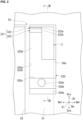
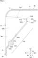
- the holder accommodation portion 52 is a recessed part opening on the front surface 51 of the front panel 50 and recessed toward the upside Dvu approaching toward the backside Dib. As illustrated in FIGS. 2 and 3 , the holder accommodation portion 52 has a holder support portion 520, a first engagement portion 521, and a side wall portion 524.
- the holder accommodation portion 52 includes an opening 50a on the front surface 51.
- the opening 50a according to the present embodiment has a rectangular shape (oblong shape) when viewed from the foreside Dif.
- the longitudinal direction of the opening 50a matches with the vertical direction Dv.
- the holder support portion 520 extends to the upside Dvu as it goes toward the backside Dib from the end edge of the opening 50a on the downside Dvd.
- the holder support portion 520 has a base end surface 520a, a fastening surface 520b, an upper surface 520c, and a support surface 520d.
- the base end surface 520a is a surface connected to the end edge of the opening 50a on the front surface 51 on the downside Dvd and inclined in a manner of being directed to the upside Dvu with respect to the front surface 51.
- the fastening surface 520b is a surface connected to the end edge on the base end surface 520a on the backside Dib and spreading in a manner of rising toward the upside Dvu from the end edge. Therefore, the fastening surface 520b is directed to the foreside Dif.
- a fastening hole 520e opening on the fastening surface 520b and recessed toward the backside Dib from this fastening surface 520b is formed in the holder support portion 520.
- the fastening hole 520e has a screw thread allowing the bolt 7 to be fastened thereto.
- the upper surface 520c is a surface connected to the end edge on the fastening surface 520b on the upside Dvu and spreads in the horizontal direction from the end edge.
- the support surface 520d is a surface connected to the end edge on the upper surface 520c on the backside Dib and inclined in a manner of being directed to the foreside Dif with respect to the upper surface 520c.
- the support surface 520d according to the present embodiment is formed to be inclined, for example by 40° to 50°, with respect to a virtual horizontal plane (spreading direction of the upper surface 520c).
- the first engagement portion 521 extends toward the upside Dvu from the end edge of the holder support portion 520 on the backside Dib.
- the first engagement portion 521 according to the present embodiment is formed of a material having flexibility.
- the first engagement portion 521 has a first base portion 522 and a first claw portion 523.
- the first base portion 522 is a member having a flat plate shape extending upward from the end edge of the holder support portion 520 on the backside Dib.
- the first base portion 522 extends in a direction intersecting a spreading direction of the support surface 520d above the support surface 520d.
- the first base portion 522 has a forward surface 522a connected to the end edge on the support surface 520d on the backside Dib and spreading in a manner of rising toward the upside Dvu from the end edge.
- the forward surface 522a is directed to the foreside Dif and connected to the support surface 520d.
- the first claw portion 523 is a member having a flat plate shape extending to the foreside Dif as it goes toward the upside Dvu from the end edge of the first base portion 522 on the upside Dvu. Therefore, the first claw portion 523 extends in a direction intersecting the spreading direction of the support surface 520d above the support surface 520d.
- the first claw portion 523 has a first surface 523a spreading in a direction perpendicular to the spreading direction of the support surface 520d and connected to the forward surface 522a, and a restraint surface 523b directed to a side opposite to the first surface 523a.
- the side wall portion 524 spreads in a manner of connecting the end edge of the opening 50a on the other side Dwl, the holder support portion 520, and the first engagement portion 521 to each other.
- the side wall portion is formed of a material having flexibility.
- the side wall portion 524 has a side wall surface 524a spreading in a direction perpendicular to the width direction Dw and directed to the one side Dwr on the other side Dwl of the holder support portion 520 and the first engagement portion 521.
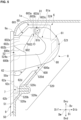
- the arm holder 6 is a member inserted into the holder accommodation portion 52 from a front side of the casing 1 and installed inside of the holder accommodation portion 52 so as to be detachable therefrom. As illustrated in FIGS. 1 and 4 , the arm holder 6 has a holding portion 60, a second engagement portion 61, and a fixed portion 62.
- the holding portion 60 has a main body portion 600 and an arm insertion portion 601 formed in the main body portion 600.
- the main body portion 600 is a member placed on the support surface 520d when being inserted into the holder accommodation portion 52, and the main body portion 600 corresponds to a main body part in the arm holder 6.
- an insertion direction Ds a direction in which the main body portion 600 is inserted into the holder accommodation portion 52
- the insertion direction Ds is a direction that matches with a direction in which the holder support portion 520 extends.
- One side, of both sides in the insertion direction Ds, in a direction away from the front surface 51 will be referred to as “a back side Dsb", and a side opposite thereto will be referred to as "a forward side Dsf'.
- the main body portion 600 has a first holder surface 600a directed to the one side Dwr, a second holder surface 600b directed to the other side Dwl that is a side opposite to the first holder surface 600a, and a third holder surface 600c connecting the first holder surface 600a and the second holder surface 600b to each other and directed to the forward side Dsf.
- the second holder surface 600b faces the side wall surface 524a of the side wall portion 524 and comes into contact therewith.
- each of the elements (the arm insertion portion 601 of the holding portion 60, the second engagement portion 61, and the fixed portion 62) provided in the arm holder 6 when the holding portion 60 is inserted into the holder accommodation portion 52 and the main body portion 600 is placed on the support surface 520d will be described.
- the arm insertion portion 601 is a groove formed to be recessed toward the other side Dwl from the first holder surface 600a of the main body portion 600.
- the arm insertion portion 601 guides and turnably holds the arm 8 (refer to FIG. 1 ) inserted into the holder accommodation portion 52 from the foreside Dif.
- the arm insertion portion 601 has a guide portion 602 and a bearing portion 603.
- the guide portion 602 guides the arm 8 inserted from the forward side Dsf to the back side Dsb.
- the guide portion 602 has a first guide surface 602a, a second guide surface 602b, and a first abutment surface 602c.
- the first guide surface 602a is a surface extending in a direction away from the front surface 51 and facing the support surface 520d of the holder support portion 520.
- the second guide surface 602b is a surface extending along the first guide surface 602a and facing the first guide surface 602a.
- the first abutment surface 602c is a surface connecting the first guide surface 602a and the second guide surface 602b to each other and directed to the one side Dwr on the other side Dwl of the first guide surface 602a and the second guide surface 602b.
- the bearing portion 603 is connected to the respective end edges of the first guide surface 602a, the second guide surface 602b, and the first abutment surface 602c on the back side Dsb from the backside Dib and holds the arm 8 guided by the guide portion 602.
- the bearing portion 603 has a bearing surface 603c, a first connection surface 603a, a second connection surface 603b, and a second abutment surface 603d.
- the bearing surface 603c is an inner circumferential surface of a half-cylinder recessed toward the backside Dib when viewed from the one side Dwr.
- the first connection surface 603a is a surface connecting the first guide surface 602a and the bearing surface 603c to each other and directed to the downside Dvd.
- the second connection surface 603b is a surface connecting the second guide surface 602b and the bearing surface 603c to each other and directed to the upside Dvu.
- the second abutment surface 603d is a surface connecting the first connection surface 603a, the second connection surface 603b, and the bearing surface 603c to each other and directed to the one side Dwr on the other side Dwl of the first guide surface 602a, the second guide surface 602b, and the bearing surface 603c.
- an inner surface of the arm insertion portion 601 serving as a groove is constituted of the first guide surface 602a, the second guide surface 602b, and the first abutment surface 602c of the guide portion 602, and the bearing surface 603c, the first connection surface 603a, the second connection surface 603b, and the second abutment surface 603d of the bearing portion 603.
- the bearing portion 603 according to the present embodiment is positioned on the upside Dvu of the opening 50a of the holder accommodation portion 52.
- the second engagement portion 61 is a member integrally formed on the main body portion 600 of the holding portion 60 so as to be protruded therefrom toward the back side Dsb from the main body portion 600 of the holding portion 60 and able to be interlocked with the first engagement portion 521.
- the second engagement portion 61 has a second base portion 610 and a second claw portion 611.
- the second base portion 610 is a member having a flat plate shape extending toward the back side Dsb from the main body portion 600.
- the second base portion 610 has a facing surface 610a facing the support surface 520d.
- the facing surface 610a spreads parallel to the spreading direction of the support surface 520d.
- the second claw portion 611 is a member having a flat plate shape extending to the backside Dib as it goes toward the downside Dvd from the end edge of the second base portion 610 on the back side Dsb.
- the second claw portion 611 according to the present embodiment has a reception surface 611b spreading in a direction perpendicular to a spreading direction of the facing surface 610a and connected to the facing surface 610a, and a second surface 611a directed to a side opposite to the reception surface 611b.
- the reception surface 611b and the second surface 611a of the second claw portion 611 spread parallel to spreading directions of the first surface 523a and the restraint surface 523b of the first claw portion 523 in the first engagement portion 521.
- the reception surface 611b and the second surface 611a of the second claw portion 611 are disposed at positions overlapping the first surface 523a and the restraint surface 523b when viewed in the insertion direction Ds.
- the first surface 523a of the first claw portion 523 receives a pressure from the second surface 611a of the second claw portion 611.
- the first engagement portion 521 since the first engagement portion 521 has flexibility, the first claw portion 523 and the first base portion 522 connected to the first claw portion 523 are bent toward the back side Dsb.
- the second surface 611a of the second claw portion 611 can go over the end edge on the first surface 523a of the first claw portion 523 and moves to the back side Dsb beyond the restraint surface 523b of the first claw portion 523. That is, the second claw portion 611 goes over the first claw portion 523 from the forward side Dsf toward the back side Dsb.
- first engagement portion 521 Since the first engagement portion 521 has flexibility, at the same time as the second claw portion 611 goes over the first claw portion 523, bending of the first claw portion 523 and the first base portion 522 toward the back side Dsb is released, and the first claw portion 523 and the first base portion 522 return to original positions.
- the restraint surface 523b of the first claw portion 523 and the reception surface 611b of the second claw portion 611 face each other in the insertion direction Ds and come into contact with each other.
- the main body portion 600 stands still on the support surface 520d. Through a series of the foregoing operation, engagement between the first engagement portion 521 and the second engagement portion 61 is completed.
- the fixed portion 62 is a member integrally formed on the main body portion 600 and fixed to the holder support portion 520.
- the fixed portion 62 itself is fixed to the holder support portion 520 so that the main body portion 600 is subjected to positioning on the support surface 520d.
- the fixed portion 62 has a fixed surface 62a extending from the main body portion 600 toward the forward side Dsf and being flush with the front surface 51 on the inner side of the opening 50a.
- a recessed groove 62b opening on the fixed surface 62a and recessed toward the backside Dib from this fixed surface 62a is formed in the fixed portion 62.
- a fixed portion fastening hole 62d opening on a groove bottom surface 62c of this recessed groove 62b and penetrating the fixed portion 62 toward the backside Dib from this groove bottom surface 62c is formed in the fixed portion 62.
- the fixed portion fastening hole 62d has a screw thread allowing the bolt 7 to be fastened thereto.
- the fixed portion 62 is subjected to spot-facing treatment such that a head portion of the bolt 7 does not protrude to the foreside Dif beyond the fixed surface 62a.
- This fixed portion fastening hole 62d provided in the fixed portion 62 is formed to have the same measurement as the fastening hole 520e provided in the holder support portion 520, is disposed from the foreside Dif with respect to this fastening hole 520e, and overlaps the fastening hole 520e in a manner of being connected thereto in the installation direction Di.
- the fixed portion 62 Due to the bolt 7 fastened to the fixed portion fastening hole 62d and the fastening hole 520e connected to each other from the foreside Dif, the fixed portion 62 is fixed to the holder support portion 520. That is, the bolt 7 is attached to the holder support portion 520 from the foreside Dif so that the fixed portion 62 is fixed to the holder support portion 520. In other words, since the bolt 7 is attached to the casing 1 from the foreside Dif, the arm holder 6 is fixed to the casing 1.
- the arm 8 is inserted into the holder accommodation portion 52 from the front side of the casing 1, and one end thereof is held by the arm holder 6 so that the arm 8 is allowed to turn around an axis O extending in the width direction Dw which is a longitudinal direction of the casing 1. As illustrated in FIGS. 1 and 5 , the arm 8 has a shaft portion 81 and an arm main body 80.
- the shaft portion 81 is a member having a columnar shape extending in the width direction Dw and having an outer circumferential surface 81a and a pair of end surfaces 81b.
- the shaft portion 81 extends in the width direction Dw in a state in which the arm 8 is inserted into the holder accommodation portion 52. That is, the end surface 81b, of the pair of end surfaces 81b arranged in the width direction Dw, on the one side Dwr is directed to the one side Dwr, and the end surface 81b, of the pair of end surfaces 81b, on the other side Dwl is directed to the other side Dwl.
- the shaft portion 81 is inserted into the holder accommodation portion 52 in a state of extending in the width direction Dw and then is inserted into the arm insertion portion 601 of the holding portion 60 in the arm holder 6.
- an insertion portion 82 a part bisecting the shaft portion 81 in the width direction Dw and positioned on the other side Dwl
- a non-insertion portion 83 a part positioned on the one side Dwr
- the shaft portion 81 which has been inserted into the holder accommodation portion 52 from the front surface 51 side is held by the bearing portion 603 of the arm insertion portion 601 in a manner of being able to turn around the axis O.
- the axis O according to the present embodiment matches with a centerline of the bearing surface 603c (a centerline of the cylinder) serving as an inner circumferential surface of a half-cylinder in the bearing portion 603.
- the shaft portion 81 in its entirety guided to the backward side Dsb by the guide portion 602 is guided to the following bearing surface 603c positioned on the backside Dib of the first connection surface 603a and the second connection surface 603b by the first connection surface 603a and the second connection surface 603b of the bearing portion 603.
- the shaft portion 81 in its entirety is held by this bearing surface 603c in a manner of being able to turn around the axis O.
- the arm main body 80 is a member connected to the shaft portion 81 and turning about the axis O in response to turning of the shaft portion 81. Specifically, one end of the arm main body 80 is fixed to the non-insertion portion 83 in the shaft portion 81. That is, the arm main body 80 integrally turns around the axis O with the shaft portion 81.
- the arm main body 80 is inserted into the holder accommodation portion 52 when the shaft portion 81 is at a position about the axis O.
- the arm main body 80 has a U-shape inclined to the foreside Dif when viewed from the one side Dwr.
- the shaft portion 81 is inserted into the holder accommodation portion 52 together with this arm main body 80 in a state in which the arm main body 80 is fixed. Therefore, the shaft portion 81 and the arm main body 80 are not separately inserted into the holder accommodation portion 52.
- the inlet panel 9 is a panel capable of shifting between a state of covering the front surface 51 of the front panel 50 from the foreside Dif and a state of not covering the front surface 51 in response to turning of the arms 8 around the axis O.
- the inlet panel 9 is connected to the other end of each of the arm main bodies 80.
- the inlet panel 9 covers the front surface 51 of the front panel 50 from the foreside Dif so as to close the main openings 53 opening on the front surface 51, and the openings 50a of the holder accommodation portions 52.
- the inlet panel 9 connected to the other end of each of the arms 8 is disposed in a manner of overlapping the front surface 51 of the front panel 50 at a position covering the openings 50a of the holder accommodation portions 52.
- the end edge of the inlet panel 9 on the upside Dvu becomes a top edge 9a.
- the top edge 9a of the inlet panel 9 is positioned below the top edge 1a of the casing 1 when the inlet panel 9 is positioned at the closed position.
- the casing 1 opens on the front surface 51, and the holder accommodation portions 52 recessed toward the upside Dvu as they go toward the backside Dib are provided. Further, the arm holders 6 respectively inserted into the holder accommodation portions 52 are fixed to the insides of the holder accommodation portions 52 in an attachable/detachable manner.
- the arms 8 turnably held by the arm holders 6 turn in a manner of being able to move between the closed position where the front surface 51 is covered such that the inlet panel 9 covers the openings 50a of the holder accommodation portions 52 and the open position where the inlet panel 9 has moved forward and upward from the closed position and the front surface 51 has opened.
- the arms 8 extending from the arm holders 6 to the inlet panel 9 can be positioned farther to the downside Dvd. That is, the openings 50a of the holder accommodation portions 52 can be positioned farther to the downside Dvd.
- the inlet panel 9 when the inlet panel 9 is positioned at the closed position where the front surface 51 side is covered, the inlet panel 9 can completely cover the openings 50a of the holder accommodation portions 52 from the front side. Namely, a good appearance when the inlet panel 9 is closed is not impaired.
- the arm holders 6 are attached and detached inside the holder accommodation portions 52, the arms 8 held by these arm holders 6 and the inlet panel 9 fixed to these arms 8 can be attached and detached with respect to the casing 1 at the same time. Therefore, the arms 8 are easily attached and detached with respect to the casing 1.
- the indoor unit 100 of the embodiment when the inlet panel 9 is positioned at the closed position, the top edge 9a of the inlet panel 9 is positioned below the top edge 1a of the casing 1.
- the inlet panel 9 can be made compact and reduced in weight.
- the arm holders 6 can be fixed to the casing 1 using simple members such as bolts 7. Therefore, it is possible to curb increase in costs and man ⁇ hour related to manufacturing of the indoor unit 100.
- the indoor unit 100 of the embodiment in a condition where the holding portions 60 of the arm holders 6 are inserted into the holder accommodation portions 52, the second engagement portions 61 of the holder accommodation portions 52 are engaged with the first engagement portions 521 of the arm holders 6. Accordingly, since the holding portions 60 stand still on the support surfaces 520d, work of fixing the fixed portions 62 to the holder support portions 520 using the bolts 7 becomes easy.
- the holding portions 60 in the arm holders 6 respectively have the guide portions 602 guiding the shaft portions 81 of the arms 8 which have been inserted into the holder accommodation portions 52 to the bearing portions 603. Therefore, the arms 8 fixed to the insides of the holder accommodation portions 52 can be simply attached to the arm holders 6.
- the bearing portions 603 are positioned on the upside Dvu of the openings 50a of the holder accommodation portions 52. That is, the shaft portions 81 of the arms 8 can be rotatably held by the arm holders 6 on the upside Dvu of the openings 50a. Accordingly, a structure which is difficult to be directly formed in the casing 1 can be realized by the arm holders 6.
- the first engagement portion 521 is formed of a material having flexibility
- the first engagement portion 521 may not be formed of a material having flexibility
- the second engagement portion 61 in place of the first engagement portion 521, may be formed of a material having flexibility
- both the first engagement portion 521 and the second engagement portion 61 may be formed of a material having flexibility.
- the indoor unit according to the embodiment is ascertained as follows, for example.
- the arms 8 extending from the arm holders 6 to the inlet panel 9 can be positioned at the downside Dvd of the inlet panel 9 in the vertical direction Dv. That is, the openings 50a of the holder accommodation portions 52 can be positioned at the downside Dvd of the inlet panel 9. Since the arm holders 6 can be installed to inside the holder accommodation portions 52 and detached from the holder accommodation portions 52 when necessary, the arms 8 held by these arm holders 6 and the inlet panel 9 fixed to these arms 8 can be installed on the casing 1 and detached therefrom at the same time.
- the indoor unit 100 according to a second aspect is the indoor unit 100 according to the first aspect, in which the top edge 9a of the inlet panel 9 may be positioned below the head step 1a of the casing 1 in the condition where the inlet panel 9 is positioned at the closed position.
- the width of the inlet panel 9 in the vertical direction Dv can be reduced and the openings 50a of the holder accommodation portions 52 can be covered by the inlet panel 9 from the front side of the casing 1.
- the indoor unit 100 according to a third aspect is the indoor unit 100 according to the first or second aspect, which may further include the bolts 7 each fastened to the casing 1 from the front side thereof to fix the arm holders 6 to the casing 1.
- the arm holders 6 can be fixed to the casing 1 using the bolts 7 as simple fastening members.
- the indoor unit 100 according to a fourth aspect is the indoor unit 100 according to the third aspect, in which the holder accommodation portions 52 each may include: the holder support portion 520 having the support surface 520d supporting the arm holder 6 from below thereof; and the first engagement portion 521 which is flexible and extending upward from the support surface in the direction intersecting the support surface.
- the arm holders 6 each may include: the holding portion 60 which is placed on the support surface 520d and holding the arm 8 so as to allow to be turned around the axis O; the second engagement portion 61 which is integrally formed on the holding portion 60 so as to be protruded therefrom and which is engaged with the first engagement portion 521 in the condition where the holding portion 60 is inserted into the holder accommodation portion 52; and the fixed portion 62 which is integrally formed on the holding portion 60 so as to be protruded therefrom and which is installed on the holder support portion 520 by fastening the bolt 7 to the casing 1.
- the holding portions 60 stand still on the support surfaces 520d, the fixed portions 62 can be easily fixed to the holder support portions 520 using the bolts 7.
- the indoor unit 100 according to a fifth aspect is the indoor unit 100 according to the fourth aspect, in which the arms 8 each may include: the arm main body 80 to which the inlet panel 9 is fixed; and the shaft portion 81 which is formed on the arm main body 80 so as to set the axis O on a center of the shaft portion 81 and which allows to turn the arm main body 80 around the axis O.
- the holding portions 60 each may include the main body portion 600 and the arm insertion portion 601 which is formed in the main body portion 600.
- the arm insertion portions 601 each may include: the guide portion 602 which is formed to guide the shaft portion 81 in a direction away from the front surface 51 while inserting the arm 8 to the holder accommodation portion 52; and the bearing portion 603 holding the shaft portion 81 guided by the guide portion 602 to the bearing portion 603 so as to allow the arm main body 80 to turn around the axis O.
- the arms 8 fixed to the insides of the holder accommodation portions 52 can be easily attached to the arm holders 6.
- the indoor unit 100 according to a sixth aspect is the indoor unit 100 according to (5), in which the bearing portion 603 may be positioned above the opening 50a of the holder accommodation portion 52.
Landscapes
- Engineering & Computer Science (AREA)
- Chemical & Material Sciences (AREA)
- Combustion & Propulsion (AREA)
- Mechanical Engineering (AREA)
- General Engineering & Computer Science (AREA)
- Air Filters, Heat-Exchange Apparatuses, And Housings Of Air-Conditioning Units (AREA)
- Compression-Type Refrigeration Machines With Reversible Cycles (AREA)
Abstract
Description
- The present disclosure relates to an indoor unit.
- For example,
Japanese Unexamined Patent Application, First Publication No. H7-260193 - Accordingly, exposure of cutout portions (notches) required for movement of arms during opening and closing of an inlet panel to the outside is avoided so that a good appearance of an indoor unit is not impaired when the inlet panel is closed.
- Incidentally, when an indoor unit is assembled, a technology allowing arms in which an inlet panel is provided to be simply attached to a casing is desired. On the other hand, during maintenance of the indoor unit, a technology allowing the arms to be simply detached from the casing is desired.
- That is, indoor units in which arms are easily attached and detached with respect to a casing and a good appearance is not impaired when an inlet panel is closed are desired.
- The present disclosure has been made in order to resolve the foregoing problems, and an object thereof is to provide an indoor unit in which arms are easily attached and detached with respect to a casing and a good appearance is not impaired when an inlet panel is closed.
- In order to resolve the foregoing problems, an indoor unit according to the present disclosure includes: a casing having a front surface and holder accommodation portions opening on the front surface and recessed so as to slope upward approaching toward a back side of the casing; arm holders which are inserted into the holder accommodation portions from a front side of the casing and which are installed inside of the holder accommodation portions so as to be detachable therefrom; arms which are inserted into the holder accommodation portions from the front side of the casing and each of which a first end is held by the arm holder so that the arm is allowed to turn around an axis extending in a longitudinal direction of the casing; and an inlet panel to which a second end of each of the arms is fixed. The range of movement of the arms around the axis is set between a closed position where the inlet panel is disposed in a manner of overlapping the front surface of the casing and openings of the holder accommodation portions are closed by the inlet panel, and an open position where the inlet panel is disposed forward and upward from the front surface of the casing and the front surface of the casing is exposed.
- According to the present disclosure, it is possible to provide an indoor unit in which arms are easily attached and detached with respect to a casing and a good appearance is not impaired when an inlet panel is closed.
-
-
FIG. 1 is a perspective view illustrating a schematic constitution of an indoor unit according to an embodiment of the present disclosure. -
FIG. 2 is a view illustrating a situation when a holder accommodation portion according to the embodiment of the present disclosure is viewed from a forward side. -
FIG. 3 is a partial cross-sectional view in a direction along line III-III inFIG. 2 . -
FIG. 4 is a view illustrating an arm holder according to the embodiment of the present disclosure. -
FIG. 5 is a view illustrating a state in which an arm according to the embodiment of the present disclosure is positioned at a closed position. -
FIG. 6 is a view illustrating a state in which the arm according to the embodiment of the present disclosure is positioned at an open position. - Hereinafter, an indoor unit according to an embodiment of the present disclosure will be described based on the drawings.
- An indoor unit is an apparatus which is provided indoors and performs indoor-air conditioning through heat exchange between a refrigerant dealing with an outdoor unit provided outdoors and indoor air. An air conditioning apparatus is constituted of an indoor unit and an outdoor unit.
- As illustrated in
FIG. 1 , anindoor unit 100 includes a casing 1, afan 2, aheat exchanger 3, aFilter part 4, acontrol unit 5, anarm holder 6, abolt 7, anarm 8 and aninlet panel 9. - The casing 1 is constituted of a plurality of panels and installed on an indoor wall surface W. The casing 1 forms an outer shell of the
indoor unit 100. The casing 1 accommodates various equipment and defines a space for circulating indoor air on an inner side. The casing 1 has aback surface panel 10, a bottom panel 20, atop surface panel 30, a pair ofside surface panels 40, afront panel 50, aconnection panel 70, and aflap 73. - The
back surface panel 10 is a panel fixed to the indoor wall surface W with a mounting plate or the like (not illustrated) therebetween. Theback surface panel 10 has aback surface 11 spreading along the wall surface W and facing the wall surface W. In the present embodiment, a direction in which theback surface 11 of theback surface panel 10 faces the wall surface W face each other will be referred to as "an installation direction Di". Therefore, the installation direction Di is a direction perpendicular to the wall surface W. - One side, of both sides in the installation direction Di, in a direction away from the wall surface W will be referred to as "a foreside Dif', and a side opposite thereto will be referred to as "a backside Dib". The
back surface 11 has an oblong shape having a direction parallel to the wall surface W, of a horizontal direction when viewed from the foreside Dif (front), as a longitudinal direction. - The bottom panel 20 is connected to a lower edge of the
back surface panel 10 and spreading in a direction intersecting the wall surface W. The bottom panel 20 according to the present embodiment spreads in the horizontal direction and is integrally connected to theback surface panel 10 in a manner of standing upright from theback surface panel 10. The bottom panel 20 has a bottom surface 21 spreading in the horizontal direction and facing below. The bottom surface 21 spreads in a direction perpendicular to a spreading direction of theback surface 11. - The
top surface panel 30 is a panel connected to an upper edge that is a side opposite to the lower edge of theback surface panel 10 and spreading in a direction intersecting the wall surface W. Thetop surface panel 30 according to the present embodiment spreads in the horizontal direction and is integrally connected to theback surface panel 10 in a manner of standing upright from theback surface panel 10. - That is, the
top surface panel 30 spreads parallel to a spreading direction of the bottom panel 20 on the upward side of the bottom panel 20. The bottom panel 20 and thetop surface panel 30 face each other at positions separated from each other. - The
top surface panel 30 has ahead step 31 spreading in the horizontal direction and directed to the upward side. Thehead step 31 spreads in a direction perpendicular to the spreading direction of theback surface 11. In the present embodiment, an end edge (side) on thehead step 31 on the foreside Dif becomes atop edge 1a of the casing 1. Thetop edge 1a is positioned on the furthest upward side in the casing 1. - In the present embodiment, a direction in which the bottom panel 20 and the
top surface panel 30 face each other will be referred to as "a vertical direction Dv". One side, of both sides in the vertical direction Dv, in a direction directed to thetop surface panel 30 from the bottom panel 20 will be simply referred to as "an upside Dvu", and the other side on a side opposite thereto will be simply referred to as "a downside Dvd". Therefore, the vertical direction Dv matches with the direction of gravity. - The bottom surface 21 of the bottom panel 20 according to the present embodiment has an oblong shape having a direction parallel to the wall surface W, of the horizontal direction when viewed from the downside Dvd (below), as the longitudinal direction. The
head step 31 of thetop surface panel 30 according to the present embodiment has an oblong shape having a direction parallel to the wall surface W, of the horizontal direction when viewed from the upside Dvu (above), as the longitudinal direction. - A plurality of
suctioning ports 32 for suctioning indoor air are formed in thetop surface panel 30. That is, thetop surface panel 30 has the plurality ofsuctioning ports 32. The plurality ofsuctioning ports 32 are arranged at equal intervals in the horizontal direction. Each of thesuctioning ports 32 penetrates thetop surface panel 30 in the vertical direction Dv. Each of thesuctioning ports 32 has a rectangular shape (oblong shape) when viewed from the upside Dvu. - The
side surface panels 40 is a panel connecting the end edges of theback surface panel 10, the bottom panel 20, and thetop surface panel 30 extending in the longitudinal direction to each other. In the present embodiment, a direction that matches with this longitudinal direction will be referred to as "a width direction Dw". Therefore, the width direction Dw is a direction perpendicular to both the installation direction Di and the vertical direction Dv. - The right side, of both sides in the width direction Dw, when the
back surface panel 10 is viewed from the foreside Dif such that thetop surface panel 30, theback surface panel 10, and the bottom panel 20 are arranged from the upside Dvu will be simply referred to as "one side Dwr", and a side opposite thereto will be simply referred to as "the other side Dwl". - One
side surface panel 40 of the pair ofside surface panels 40 has aside surface 41 connecting the end edges of theback surface panel 10, the bottom panel 20, and thetop surface panel 30 on the one side Dwr to each other and directed to the one side Dwr. - The other
side surface panel 40 of the pair ofside surface panels 40 has anotherside surface 41 connecting the end edges of theback surface panel 10, the bottom panel 20, and thetop surface panel 30 on the other side Dwl to each other and directed to the other side Dwl. - Therefore, the pair of
side surface panels 40 are disposed such that theback surface panel 10, the bottom panel 20, and thetop surface panel 30 are sandwiched therebetween in the width direction Dw. Each of the side surfaces 41 spreads in a direction perpendicular to any of the directions in which theback surface 11, the bottom surface 21, and thehead step 31 respectively spread. - The
front panel 50 is disposed on the foreside Dif of theback surface panel 10 and connects the end edges of thetop surface panel 30 and the pair ofside surface panels 40 on the foreside Dif to each other. Thefront panel 50 spreads parallel to a spreading direction of theback surface panel 10. Thefront panel 50 has afront surface 51 spreading in a direction along the wall surface W and directed to the foreside Dif. - A pair of
main openings 53 and a pair ofholder accommodation portions 52 are formed in thefront panel 50. That is, thefront panel 50 has the pair ofmain openings 53 and the pair ofholder accommodation portions 52. The pair ofmain openings 53 are disposed in a manner of being adjacent to each other in the width direction Dw. Each of themain openings 53 when viewed from the foreside Dif has an oblong shape having the width direction Dw as the longitudinal direction. - The pair of
holder accommodation portions 52 are arranged in the width direction Dw. Oneholder accommodation portion 52 of the pair ofholder accommodation portions 52 is disposed on the one side Dwr of themain opening 53, of the pair ofmain openings 53 adjacent to each other in the width direction Dw, disposed on the one side Dwr. - The other
holder accommodation portion 52 of the pair ofholder accommodation portions 52 is disposed on the other side Dwl of themain opening 53, of the pair ofmain openings 53 adjacent to each other in the width direction Dw, disposed on the other side Dwl. The detailed constitution of theholder accommodation portions 52 will be described below. - The
connection panel 70 is a panel disposed on the downside Dvd of thefront panel 50 and connecting the end edges of the bottom panel 20 and the pair ofside surface panels 40 on the foreside Dif and the end edge of thefront panel 50 on the downside Dvd to each other. - The
connection panel 70 has aconnection surface 71 having a curved surface directed to the foreside Dif as it goes toward the end edge of thefront panel 50 on the downside Dvd from the end edge of the bottom panel 20 on the foreside Dif. - A
discharge port 72 for discharging air which has been suctioned through the suctioningports 32 of thetop surface panel 30 is formed in theconnection panel 70. That is, theconnection panel 70 has thedischarge port 72. Thedischarge port 72 when viewed from the foreside Dif or the downside Dvd is formed to have a rectangular shape (oblong shape) having the width direction Dw as the longitudinal direction. Thedischarge port 72 according to the present embodiment spreads along the curve of theconnection surface 71. - The
flap 73 is provided in thedischarge port 72 of theconnection panel 70 and changes a direction of air discharged through thedischarge port 72. Theflap 73 can shift between a state of covering thedischarge port 72 from the foreside Dif and a state of not covering thedischarge port 72. - For example, the
flap 73 is provided in theconnection panel 70 and supported by a turning shaft (not illustrated) about a turning axis (not illustrated) extending in the width direction Dw in a manner of being able to turn around the turning axis. For example, a turning amount of theflap 73 is controlled on the basis of an input signal input from the outside. - As described above, a space for accommodating various equipment and circulating indoor air is formed by each of the elements constituting the casing 1. For the sake of convenience of description, in the present embodiment, this space will be referred to as "an accommodation space R".
- The
fan 2 is a cross-flow fan which can introduce indoor air into the casing 1. Thefan 2 extends in the width direction Dw inside the accommodation space R. Thefan 2 is held by theback surface panel 10 about a rotation shaft (not illustrated) extending in the width direction Dw in a manner of being able to rotate around the rotation shaft. - The
fan 2 rotates inside the accommodation space R so as to suction air through the suctioningports 32 of thetop surface panel 30 and discharge suctioned air through thedischarge port 72 of the bottom panel 20. For example, a rotation frequency of thefan 2 is controlled on the basis of an input signal input from the outside. - The
heat exchanger 3 performs heat exchange between air introduced into the accommodation space R by thefan 2 and a refrigerant. That is, theheat exchanger 3 cools or warms air introduced into the accommodation space R. Theheat exchanger 3 is constituted of a heat transfer pipe in which the refrigerant circulates, a plurality of fins through which this heat transfer pipe is inserted in the width direction Dw, and the like. For example, theheat exchanger 3 is provided in a manner of surrounding thefan 2 from the upside Dvu inside the accommodation space R. - The
filter part 4 filters impurities such as dust included in air suctioned through the suctioningports 32 of thetop surface panel 30. Thefilter part 4 is disposed on the upside Dvu of theheat exchanger 3 inside the accommodation space R. That is, thefilter part 4 is disposed between the casing 1 and theheat exchanger 3. Therefore, thefilter part 4 supplies air from which impurities such as dust have been eliminated to theheat exchanger 3. - The
control unit 5 is a device for controlling the turning amount of theflap 73, rotation of thefan 2, and the like. Thecontrol unit 5 is connected to theflap 73 and thefan 2 by wire or radio. Thecontrol unit 5 is provided inside the accommodation space R and disposed on the one side Dwr of thefan 2, theheat exchanger 3, and thefilter part 4. - For example, when the
indoor unit 100 includes a sensor (not illustrated) provided in the casing 1, thecontrol unit 5 generates an input signal on the basis of detected information acquired by the sensor. Thecontrol unit 5 transmits a generated input signal to theflap 73 or thefan 2. - Here, a constitution of the pair of
holder accommodation portions 52 provided in thefront panel 50 will be described. When thefront panel 50 is viewed from the foreside Dif, the pair ofholder accommodation portions 52 are disposed with a relationship of bilateral symmetry therebetween. - Hereinafter, the
holder accommodation portion 52, of the pair ofholder accommodation portions 52 provided in thefront panel 50, disposed on the one side Dwr will be described. Description of theholder accommodation portion 52 disposed on the other side Dwl will be omitted. - The
holder accommodation portion 52 is a recessed part opening on thefront surface 51 of thefront panel 50 and recessed toward the upside Dvu approaching toward the backside Dib. As illustrated inFIGS. 2 and3 , theholder accommodation portion 52 has aholder support portion 520, afirst engagement portion 521, and aside wall portion 524. - The
holder accommodation portion 52 includes anopening 50a on thefront surface 51. Theopening 50a according to the present embodiment has a rectangular shape (oblong shape) when viewed from the foreside Dif. The longitudinal direction of theopening 50a matches with the vertical direction Dv. - The
holder support portion 520 extends to the upside Dvu as it goes toward the backside Dib from the end edge of theopening 50a on the downside Dvd. Theholder support portion 520 has abase end surface 520a, afastening surface 520b, anupper surface 520c, and asupport surface 520d. Thebase end surface 520a is a surface connected to the end edge of theopening 50a on thefront surface 51 on the downside Dvd and inclined in a manner of being directed to the upside Dvu with respect to thefront surface 51. - The
fastening surface 520b is a surface connected to the end edge on thebase end surface 520a on the backside Dib and spreading in a manner of rising toward the upside Dvu from the end edge. Therefore, thefastening surface 520b is directed to the foreside Dif. - A
fastening hole 520e opening on thefastening surface 520b and recessed toward the backside Dib from thisfastening surface 520b is formed in theholder support portion 520. Thefastening hole 520e has a screw thread allowing thebolt 7 to be fastened thereto. - The
upper surface 520c is a surface connected to the end edge on thefastening surface 520b on the upside Dvu and spreads in the horizontal direction from the end edge. Thesupport surface 520d is a surface connected to the end edge on theupper surface 520c on the backside Dib and inclined in a manner of being directed to the foreside Dif with respect to theupper surface 520c. Thesupport surface 520d according to the present embodiment is formed to be inclined, for example by 40° to 50°, with respect to a virtual horizontal plane (spreading direction of theupper surface 520c). - The
first engagement portion 521 extends toward the upside Dvu from the end edge of theholder support portion 520 on the backside Dib. Thefirst engagement portion 521 according to the present embodiment is formed of a material having flexibility. Thefirst engagement portion 521 has afirst base portion 522 and afirst claw portion 523. Thefirst base portion 522 is a member having a flat plate shape extending upward from the end edge of theholder support portion 520 on the backside Dib. - Therefore, the
first base portion 522 extends in a direction intersecting a spreading direction of thesupport surface 520d above thesupport surface 520d. Thefirst base portion 522 has aforward surface 522a connected to the end edge on thesupport surface 520d on the backside Dib and spreading in a manner of rising toward the upside Dvu from the end edge. Theforward surface 522a is directed to the foreside Dif and connected to thesupport surface 520d. - The
first claw portion 523 is a member having a flat plate shape extending to the foreside Dif as it goes toward the upside Dvu from the end edge of thefirst base portion 522 on the upside Dvu. Therefore, thefirst claw portion 523 extends in a direction intersecting the spreading direction of thesupport surface 520d above thesupport surface 520d. - The
first claw portion 523 according to the present embodiment has afirst surface 523a spreading in a direction perpendicular to the spreading direction of thesupport surface 520d and connected to theforward surface 522a, and arestraint surface 523b directed to a side opposite to thefirst surface 523a. - The
side wall portion 524 spreads in a manner of connecting the end edge of theopening 50a on the other side Dwl, theholder support portion 520, and thefirst engagement portion 521 to each other. The side wall portion is formed of a material having flexibility. - The
side wall portion 524 has aside wall surface 524a spreading in a direction perpendicular to the width direction Dw and directed to the one side Dwr on the other side Dwl of theholder support portion 520 and thefirst engagement portion 521. - The
arm holder 6 is a member inserted into theholder accommodation portion 52 from a front side of the casing 1 and installed inside of theholder accommodation portion 52 so as to be detachable therefrom. As illustrated inFIGS. 1 and4 , thearm holder 6 has a holdingportion 60, asecond engagement portion 61, and a fixedportion 62. - The holding
portion 60 has amain body portion 600 and anarm insertion portion 601 formed in themain body portion 600. Themain body portion 600 is a member placed on thesupport surface 520d when being inserted into theholder accommodation portion 52, and themain body portion 600 corresponds to a main body part in thearm holder 6. - Here, a direction in which the
main body portion 600 is inserted into theholder accommodation portion 52 will be referred to as "an insertion direction Ds". The insertion direction Ds is a direction that matches with a direction in which theholder support portion 520 extends. One side, of both sides in the insertion direction Ds, in a direction away from thefront surface 51 will be referred to as "a back side Dsb", and a side opposite thereto will be referred to as "a forward side Dsf'. - The
main body portion 600 has afirst holder surface 600a directed to the one side Dwr, asecond holder surface 600b directed to the other side Dwl that is a side opposite to thefirst holder surface 600a, and athird holder surface 600c connecting thefirst holder surface 600a and thesecond holder surface 600b to each other and directed to the forward side Dsf. When themain body portion 600 is inserted into theholder accommodation portion 52, thesecond holder surface 600b faces theside wall surface 524a of theside wall portion 524 and comes into contact therewith. - Hereinafter, a constitution of each of the elements (the
arm insertion portion 601 of the holdingportion 60, thesecond engagement portion 61, and the fixed portion 62) provided in thearm holder 6 when the holdingportion 60 is inserted into theholder accommodation portion 52 and themain body portion 600 is placed on thesupport surface 520d will be described. - As illustrated in
FIG. 4 , thearm insertion portion 601 is a groove formed to be recessed toward the other side Dwl from thefirst holder surface 600a of themain body portion 600. Thearm insertion portion 601 guides and turnably holds the arm 8 (refer toFIG. 1 ) inserted into theholder accommodation portion 52 from the foreside Dif. Thearm insertion portion 601 has aguide portion 602 and a bearingportion 603. - The
guide portion 602 guides thearm 8 inserted from the forward side Dsf to the back side Dsb. Theguide portion 602 has afirst guide surface 602a, asecond guide surface 602b, and afirst abutment surface 602c. - The
first guide surface 602a is a surface extending in a direction away from thefront surface 51 and facing thesupport surface 520d of theholder support portion 520. Thesecond guide surface 602b is a surface extending along thefirst guide surface 602a and facing thefirst guide surface 602a. - The
first abutment surface 602c is a surface connecting thefirst guide surface 602a and thesecond guide surface 602b to each other and directed to the one side Dwr on the other side Dwl of thefirst guide surface 602a and thesecond guide surface 602b. - The end edges of the
first guide surface 602a, thesecond guide surface 602b, and thefirst abutment surface 602c on the forward side Dsf lead to thethird holder surface 600c in themain body portion 600. Therefore, theguide portion 602 serving as a groove opens on thethird holder surface 600c. - The bearing
portion 603 is connected to the respective end edges of thefirst guide surface 602a, thesecond guide surface 602b, and thefirst abutment surface 602c on the back side Dsb from the backside Dib and holds thearm 8 guided by theguide portion 602. The bearingportion 603 has abearing surface 603c, afirst connection surface 603a, asecond connection surface 603b, and asecond abutment surface 603d. - The bearing
surface 603c is an inner circumferential surface of a half-cylinder recessed toward the backside Dib when viewed from the one side Dwr. Thefirst connection surface 603a is a surface connecting thefirst guide surface 602a and thebearing surface 603c to each other and directed to the downside Dvd. Thesecond connection surface 603b is a surface connecting thesecond guide surface 602b and thebearing surface 603c to each other and directed to the upside Dvu. - The
second abutment surface 603d is a surface connecting thefirst connection surface 603a, thesecond connection surface 603b, and thebearing surface 603c to each other and directed to the one side Dwr on the other side Dwl of thefirst guide surface 602a, thesecond guide surface 602b, and thebearing surface 603c. - Therefore, an inner surface of the
arm insertion portion 601 serving as a groove is constituted of thefirst guide surface 602a, thesecond guide surface 602b, and thefirst abutment surface 602c of theguide portion 602, and thebearing surface 603c, thefirst connection surface 603a, thesecond connection surface 603b, and thesecond abutment surface 603d of the bearingportion 603. The bearingportion 603 according to the present embodiment is positioned on the upside Dvu of theopening 50a of theholder accommodation portion 52. - The
second engagement portion 61 is a member integrally formed on themain body portion 600 of the holdingportion 60 so as to be protruded therefrom toward the back side Dsb from themain body portion 600 of the holdingportion 60 and able to be interlocked with thefirst engagement portion 521. Thesecond engagement portion 61 has asecond base portion 610 and asecond claw portion 611. - The
second base portion 610 is a member having a flat plate shape extending toward the back side Dsb from themain body portion 600. Thesecond base portion 610 has a facingsurface 610a facing thesupport surface 520d. The facingsurface 610a spreads parallel to the spreading direction of thesupport surface 520d. - The
second claw portion 611 is a member having a flat plate shape extending to the backside Dib as it goes toward the downside Dvd from the end edge of thesecond base portion 610 on the back side Dsb. Thesecond claw portion 611 according to the present embodiment has areception surface 611b spreading in a direction perpendicular to a spreading direction of the facingsurface 610a and connected to the facingsurface 610a, and asecond surface 611a directed to a side opposite to thereception surface 611b. - Therefore, the
reception surface 611b and thesecond surface 611a of thesecond claw portion 611 spread parallel to spreading directions of thefirst surface 523a and therestraint surface 523b of thefirst claw portion 523 in thefirst engagement portion 521. Thereception surface 611b and thesecond surface 611a of thesecond claw portion 611 are disposed at positions overlapping thefirst surface 523a and therestraint surface 523b when viewed in the insertion direction Ds. - Here, a form related to involvement between the
first engagement portion 521 and thesecond engagement portion 61 when themain body portion 600 is inserted into theholder accommodation portion 52 will be described. When themain body portion 600 is inserted toward the back side Dsb in theholder accommodation portion 52, thesecond surface 611a of thesecond claw portion 611 comes into contact with thefirst surface 523a of thefirst claw portion 523. - When the
main body portion 600 is further inserted toward the back side Dsb from a position where thefirst surface 523a and thesecond surface 611a come into contact with each other, thefirst surface 523a of thefirst claw portion 523 receives a pressure from thesecond surface 611a of thesecond claw portion 611. At this time, since thefirst engagement portion 521 has flexibility, thefirst claw portion 523 and thefirst base portion 522 connected to thefirst claw portion 523 are bent toward the back side Dsb. - Due to bending of the
first claw portion 523 and thefirst base portion 522 toward the back side Dsb, thesecond surface 611a of thesecond claw portion 611 can go over the end edge on thefirst surface 523a of thefirst claw portion 523 and moves to the back side Dsb beyond therestraint surface 523b of thefirst claw portion 523. That is, thesecond claw portion 611 goes over thefirst claw portion 523 from the forward side Dsf toward the back side Dsb. - Since the
first engagement portion 521 has flexibility, at the same time as thesecond claw portion 611 goes over thefirst claw portion 523, bending of thefirst claw portion 523 and thefirst base portion 522 toward the back side Dsb is released, and thefirst claw portion 523 and thefirst base portion 522 return to original positions. - When the
first claw portion 523 and thefirst base portion 522 return to the original positions and insertion of themain body portion 600 to the back side Dsb ends, therestraint surface 523b of thefirst claw portion 523 and thereception surface 611b of thesecond claw portion 611 face each other in the insertion direction Ds and come into contact with each other. - At this time, due to a dead weight of the
main body portion 600, a tensile force is applied to the second engagement portion 61 (thesecond claw portion 611 and the second base portion 610) toward the forward side Dsf, but thereception surface 611b of thesecond claw portion 611 is pressed by therestraint surface 523b of thefirst claw portion 523 so as to receive a force toward the back side Dsb from thisrestraint surface 523b. - Due to a balance between a force applied to the
restraint surface 523b from thereception surface 611b on the basis of the dead weight of themain body portion 600 and a force applied to thereception surface 611b from therestraint surface 523b on the basis of a material constituting thefirst engagement portion 521 having flexibility, themain body portion 600 stands still on thesupport surface 520d. Through a series of the foregoing operation, engagement between thefirst engagement portion 521 and thesecond engagement portion 61 is completed. - The fixed
portion 62 is a member integrally formed on themain body portion 600 and fixed to theholder support portion 520. The fixedportion 62 itself is fixed to theholder support portion 520 so that themain body portion 600 is subjected to positioning on thesupport surface 520d. - The fixed
portion 62 has a fixedsurface 62a extending from themain body portion 600 toward the forward side Dsf and being flush with thefront surface 51 on the inner side of theopening 50a. A recessedgroove 62b opening on the fixedsurface 62a and recessed toward the backside Dib from this fixedsurface 62a is formed in the fixedportion 62. - Further, a fixed
portion fastening hole 62d opening on agroove bottom surface 62c of this recessedgroove 62b and penetrating the fixedportion 62 toward the backside Dib from this groovebottom surface 62c is formed in the fixedportion 62. The fixedportion fastening hole 62d has a screw thread allowing thebolt 7 to be fastened thereto. - That is, the fixed
portion 62 according to the present embodiment is subjected to spot-facing treatment such that a head portion of thebolt 7 does not protrude to the foreside Dif beyond the fixedsurface 62a. This fixedportion fastening hole 62d provided in the fixedportion 62 is formed to have the same measurement as thefastening hole 520e provided in theholder support portion 520, is disposed from the foreside Dif with respect to thisfastening hole 520e, and overlaps thefastening hole 520e in a manner of being connected thereto in the installation direction Di. - Due to the
bolt 7 fastened to the fixedportion fastening hole 62d and thefastening hole 520e connected to each other from the foreside Dif, the fixedportion 62 is fixed to theholder support portion 520. That is, thebolt 7 is attached to theholder support portion 520 from the foreside Dif so that the fixedportion 62 is fixed to theholder support portion 520. In other words, since thebolt 7 is attached to the casing 1 from the foreside Dif, thearm holder 6 is fixed to the casing 1. - The
arm 8 is inserted into theholder accommodation portion 52 from the front side of the casing 1, and one end thereof is held by thearm holder 6 so that thearm 8 is allowed to turn around an axis O extending in the width direction Dw which is a longitudinal direction of the casing 1. As illustrated inFIGS. 1 and5 , thearm 8 has ashaft portion 81 and an armmain body 80. - The
shaft portion 81 is a member having a columnar shape extending in the width direction Dw and having an outercircumferential surface 81a and a pair ofend surfaces 81b. Theshaft portion 81 extends in the width direction Dw in a state in which thearm 8 is inserted into theholder accommodation portion 52. That is, theend surface 81b, of the pair of end surfaces 81b arranged in the width direction Dw, on the one side Dwr is directed to the one side Dwr, and theend surface 81b, of the pair ofend surfaces 81b, on the other side Dwl is directed to the other side Dwl. - The
shaft portion 81 is inserted into theholder accommodation portion 52 in a state of extending in the width direction Dw and then is inserted into thearm insertion portion 601 of the holdingportion 60 in thearm holder 6. In the present embodiment, for the sake of convenience of description, a part bisecting theshaft portion 81 in the width direction Dw and positioned on the other side Dwl will be referred to as "aninsertion portion 82", and a part positioned on the one side Dwr will be referred to as "anon-insertion portion 83". Therefore, only theinsertion portion 82 of theshaft portion 81 is inserted into thearm insertion portion 601 from thefront surface 51 side. - The
shaft portion 81 which has been inserted into theholder accommodation portion 52 from thefront surface 51 side is held by the bearingportion 603 of thearm insertion portion 601 in a manner of being able to turn around the axis O. The axis O according to the present embodiment matches with a centerline of the bearingsurface 603c (a centerline of the cylinder) serving as an inner circumferential surface of a half-cylinder in the bearingportion 603. - Here, a form when the
shaft portion 81 is inserted into thearm insertion portion 601 will be described. When theinsertion portion 82 in theshaft portion 81 is inserted between thefirst guide surface 602a and thesecond guide surface 602b of theguide portion 602 in thearm insertion portion 601, the outercircumferential surface 81a of theinsertion portion 82 comes into contact with thefirst guide surface 602a or thesecond guide surface 602b. Theend surface 81b directed to the other side Dwl of theinsertion portion 82 abuts thefirst abutment surface 602c. - When a force causing the
shaft portion 81 to be directed to the upside Dvu or the backside Dib is applied, while the outercircumferential surface 81a of theinsertion portion 82 comes into sliding contact with thefirst guide surface 602a or thesecond guide surface 602b and theend surface 81b directed to the other side Dwl comes into sliding contact with thefirst abutment surface 602c, theshaft portion 81 in its entirety is guided in a direction in which thefirst guide surface 602a and thesecond guide surface 602b extend, that is, to the backward side Dsb. - The outer
circumferential surface 81a of theinsertion portion 82 after being guided to the backward side Dsb by theguide portion 602 comes into sliding contact with thefirst connection surface 603a or thesecond connection surface 603b of the bearingportion 603, and theend surface 81b directed to the other side Dwl is guided to the backside Dib by thefirst connection surface 603a and thesecond connection surface 603b while coming into sliding contact with thesecond abutment surface 603d. - Therefore, the
shaft portion 81 in its entirety guided to the backward side Dsb by theguide portion 602 is guided to the followingbearing surface 603c positioned on the backside Dib of thefirst connection surface 603a and thesecond connection surface 603b by thefirst connection surface 603a and thesecond connection surface 603b of the bearingportion 603. When theinsertion portion 82 is guided to a position where it comes into contact with the bearingsurface 603c, theshaft portion 81 in its entirety is held by this bearingsurface 603c in a manner of being able to turn around the axis O. - The arm
main body 80 is a member connected to theshaft portion 81 and turning about the axis O in response to turning of theshaft portion 81. Specifically, one end of the armmain body 80 is fixed to thenon-insertion portion 83 in theshaft portion 81. That is, the armmain body 80 integrally turns around the axis O with theshaft portion 81. - The arm
main body 80 is inserted into theholder accommodation portion 52 when theshaft portion 81 is at a position about the axis O. The armmain body 80 has a U-shape inclined to the foreside Dif when viewed from the one side Dwr. Theshaft portion 81 is inserted into theholder accommodation portion 52 together with this armmain body 80 in a state in which the armmain body 80 is fixed. Therefore, theshaft portion 81 and the armmain body 80 are not separately inserted into theholder accommodation portion 52. - The
inlet panel 9 is a panel capable of shifting between a state of covering thefront surface 51 of thefront panel 50 from the foreside Dif and a state of not covering thefront surface 51 in response to turning of thearms 8 around the axis O. Theinlet panel 9 is connected to the other end of each of the armmain bodies 80. - The
inlet panel 9 covers thefront surface 51 of thefront panel 50 from the foreside Dif so as to close themain openings 53 opening on thefront surface 51, and theopenings 50a of theholder accommodation portions 52. - Here, a form of the
inlet panel 9 when thearms 8 turn will be described. As illustrated inFIG. 5 , before thearms 8 turn, theinlet panel 9 connected to the other end of each of thearms 8 is disposed in a manner of overlapping thefront surface 51 of thefront panel 50 at a position covering theopenings 50a of theholder accommodation portions 52. - On the other hand, as illustrated in
FIG. 6 , when thearms 8 turn around the axis O, theinlet panel 9 connected to the other end of each of thearms 8 moves to the foreside Dif and the upside Dvu from the position covering theopenings 50a and shifts to the position where thefront surface 51 is opened. In the present embodiment, the former position (FIG. 5 ) will be referred to as "a closed position", and the latter position (FIG. 6 ) will be referred to as "an open position". - In the present embodiment, the end edge of the
inlet panel 9 on the upside Dvu becomes atop edge 9a. Thetop edge 9a of theinlet panel 9 is positioned below thetop edge 1a of the casing 1 when theinlet panel 9 is positioned at the closed position. - According to the
indoor unit 100 of the embodiment, the casing 1 opens on thefront surface 51, and theholder accommodation portions 52 recessed toward the upside Dvu as they go toward the backside Dib are provided. Further, thearm holders 6 respectively inserted into theholder accommodation portions 52 are fixed to the insides of theholder accommodation portions 52 in an attachable/detachable manner. - Further, the
arms 8 turnably held by thearm holders 6 turn in a manner of being able to move between the closed position where thefront surface 51 is covered such that theinlet panel 9 covers theopenings 50a of theholder accommodation portions 52 and the open position where theinlet panel 9 has moved forward and upward from the closed position and thefront surface 51 has opened. - Accordingly, when the
inlet panel 9 is positioned at the open position, for example, compared to a constitution having theholder accommodation portions 52 simply recessed to be directed to the backside Dib, thearms 8 extending from thearm holders 6 to theinlet panel 9 can be positioned farther to the downside Dvd. That is, theopenings 50a of theholder accommodation portions 52 can be positioned farther to the downside Dvd. - In other words, it is possible to curb a situation in which the
openings 50a on thefront surface 51 are positioned on the upside Dvu. Therefore, when theinlet panel 9 is positioned at the closed position where thefront surface 51 side is covered, theinlet panel 9 can completely cover theopenings 50a of theholder accommodation portions 52 from the front side. Namely, a good appearance when theinlet panel 9 is closed is not impaired. - In addition, since the
arm holders 6 are attached and detached inside theholder accommodation portions 52, thearms 8 held by thesearm holders 6 and theinlet panel 9 fixed to thesearms 8 can be attached and detached with respect to the casing 1 at the same time. Therefore, thearms 8 are easily attached and detached with respect to the casing 1. - In addition, according to the
indoor unit 100 of the embodiment, when theinlet panel 9 is positioned at the closed position, thetop edge 9a of theinlet panel 9 is positioned below thetop edge 1a of the casing 1. - That is, since the
openings 50a of theholder accommodation portions 52 can be positioned farther to the downside Dvd, the measurement of theinlet panel 9 in the vertical direction Dv can be reduced and theinlet panel 9 can cover theopenings 50a of theholder accommodation portions 52 from the front side. Therefore, theinlet panel 9 can be made compact and reduced in weight. - In addition, according to the
indoor unit 100 of the embodiment, thearm holders 6 can be fixed to the casing 1 using simple members such asbolts 7. Therefore, it is possible to curb increase in costs and man□hour related to manufacturing of theindoor unit 100. - In addition, according to the
indoor unit 100 of the embodiment, in a condition where the holdingportions 60 of thearm holders 6 are inserted into theholder accommodation portions 52, thesecond engagement portions 61 of theholder accommodation portions 52 are engaged with thefirst engagement portions 521 of thearm holders 6. Accordingly, since the holdingportions 60 stand still on the support surfaces 520d, work of fixing the fixedportions 62 to theholder support portions 520 using thebolts 7 becomes easy. - In addition, according to the
indoor unit 100 of the embodiment, the holdingportions 60 in thearm holders 6 respectively have theguide portions 602 guiding theshaft portions 81 of thearms 8 which have been inserted into theholder accommodation portions 52 to the bearingportions 603. Therefore, thearms 8 fixed to the insides of theholder accommodation portions 52 can be simply attached to thearm holders 6. - In addition, according to the
indoor unit 100 of the embodiment, the bearingportions 603 are positioned on the upside Dvu of theopenings 50a of theholder accommodation portions 52. That is, theshaft portions 81 of thearms 8 can be rotatably held by thearm holders 6 on the upside Dvu of theopenings 50a. Accordingly, a structure which is difficult to be directly formed in the casing 1 can be realized by thearm holders 6. - Hereinabove, an embodiment of the present disclosure has been described in detail with reference to the drawings. However, specific constitutions are not limited to the constitutions of the embodiment, and addition, omission, replacement, and other changes of the constitutions can be made within a range not departing from the gist of the present disclosure. In addition, the present disclosure is not limited by the embodiment and is limited by only the claims.
- In the embodiment, a constitution in which the
first engagement portion 521 is formed of a material having flexibility has been described, but it is not limited to this constitution. For example, thefirst engagement portion 521 may not be formed of a material having flexibility, and thesecond engagement portion 61, in place of thefirst engagement portion 521, may be formed of a material having flexibility. In addition, both thefirst engagement portion 521 and thesecond engagement portion 61 may be formed of a material having flexibility. - The indoor unit according to the embodiment is ascertained as follows, for example.
- (1) The
indoor unit 100 according to a first aspect includes: the casing 1 having thefront surface 51 and theholder accommodation portions 52 opening on thefront surface 51 and recessed so as to slope upward approaching toward a back side of the casing; thearm holders 6 which are inserted into theholder accommodation portions 52 from the front side of the casing 1 and which are installed inside of theholder accommodation portions 52 so as to be detachable therefrom; thearms 8 which are inserted into theholder accommodation portions 52 from the front side of the casing 1 and each of which a first end is held by thearm holder 6 so that the arm is allowed to turn around the axis O extending in the longitudinal direction Dw of the casing 1; and theinlet panel 9 to which a second end of each of thearms 8 is fixed. The range of movement of thearms 8 around the axis O is set between the closed position where theinlet panel 9 is disposed in a manner of overlapping thefront surface 51 of the casing 1 and theopenings 50a of theholder accommodation portions 52 are closed by theinlet panel 9, and the open position where theinlet panel 9 is disposed forward and upward from thefront surface 51 of the casing 1 and thefront surface 51 of the casing 1 are exposed. - Accordingly, in a state where the
inlet panel 9 is placed at the open position, thearms 8 extending from thearm holders 6 to theinlet panel 9 can be positioned at the downside Dvd of theinlet panel 9 in the vertical direction Dv. That is, theopenings 50a of theholder accommodation portions 52 can be positioned at the downside Dvd of theinlet panel 9. Since thearm holders 6 can be installed to inside theholder accommodation portions 52 and detached from theholder accommodation portions 52 when necessary, thearms 8 held by thesearm holders 6 and theinlet panel 9 fixed to thesearms 8 can be installed on the casing 1 and detached therefrom at the same time. - (2) The
indoor unit 100 according to a second aspect is theindoor unit 100 according to the first aspect, in which thetop edge 9a of theinlet panel 9 may be positioned below thehead step 1a of the casing 1 in the condition where theinlet panel 9 is positioned at the closed position. - Accordingly, the width of the
inlet panel 9 in the vertical direction Dv can be reduced and theopenings 50a of theholder accommodation portions 52 can be covered by theinlet panel 9 from the front side of the casing 1. - (3) The
indoor unit 100 according to a third aspect is theindoor unit 100 according to the first or second aspect, which may further include thebolts 7 each fastened to the casing 1 from the front side thereof to fix thearm holders 6 to the casing 1. - Accordingly, the
arm holders 6 can be fixed to the casing 1 using thebolts 7 as simple fastening members. - (4) The
indoor unit 100 according to a fourth aspect is theindoor unit 100 according to the third aspect, in which theholder accommodation portions 52 each may include: theholder support portion 520 having thesupport surface 520d supporting thearm holder 6 from below thereof; and thefirst engagement portion 521 which is flexible and extending upward from the support surface in the direction intersecting the support surface. Thearm holders 6 each may include: the holdingportion 60 which is placed on thesupport surface 520d and holding thearm 8 so as to allow to be turned around the axis O; thesecond engagement portion 61 which is integrally formed on the holdingportion 60 so as to be protruded therefrom and which is engaged with thefirst engagement portion 521 in the condition where the holdingportion 60 is inserted into theholder accommodation portion 52; and the fixedportion 62 which is integrally formed on the holdingportion 60 so as to be protruded therefrom and which is installed on theholder support portion 520 by fastening thebolt 7 to the casing 1. - Accordingly, since the holding
portions 60 stand still on the support surfaces 520d, the fixedportions 62 can be easily fixed to theholder support portions 520 using thebolts 7. - (5) The
indoor unit 100 according to a fifth aspect is theindoor unit 100 according to the fourth aspect, in which thearms 8 each may include: the armmain body 80 to which theinlet panel 9 is fixed; and theshaft portion 81 which is formed on the armmain body 80 so as to set the axis O on a center of theshaft portion 81 and which allows to turn the armmain body 80 around the axis O. The holdingportions 60 each may include themain body portion 600 and thearm insertion portion 601 which is formed in themain body portion 600. Thearm insertion portions 601 each may include: theguide portion 602 which is formed to guide theshaft portion 81 in a direction away from thefront surface 51 while inserting thearm 8 to theholder accommodation portion 52; and the bearingportion 603 holding theshaft portion 81 guided by theguide portion 602 to the bearingportion 603 so as to allow the armmain body 80 to turn around the axis O. - Accordingly, the
arms 8 fixed to the insides of theholder accommodation portions 52 can be easily attached to thearm holders 6. - (6) The
indoor unit 100 according to a sixth aspect is theindoor unit 100 according to (5), in which thebearing portion 603 may be positioned above theopening 50a of theholder accommodation portion 52. - Accordingly, a structure having a formation which is difficult to mold as one-piece in the casing 1 can be realized using the
arm holders 6. -
- 1a, 9a Top edge
- 2 Fan
- 3 Heat exchanger
- 4 Filter part
- 5 Control unit
- 6 Arm holder
- 7 Bolt
- 8 Arm
- 9 Inlet panel
- 10 Back surface panel
- 11 Back surface
- 20 Bottom panel
- 21 Bottom surface
- 30 Top surface panel
- 31 Top surface
- 32 Suctioning ports
- 40 Side surface panel
- 41 Side surface
- 50 Front panel
- 50a Opening
- 51 Front surface
- 52 Holder accommodation portion
- 53 Main openings
- 60 Holding portion
- 61 Second engagement portion
- 62 Fixed portion
- 62a Fixed surface
- 62b Recessed groove
- 62c Groove bottom surface
- 62d Fixed portion fastening hole
- 70 Connection panel
- 71 Connection surface
- 72 Discharge port
- 73 Flap
- 80 Arm main body
- 81 Shaft portion
- 81a Outer circumferential surface
- 81b End surface
- 82 Insertion portion
- 83 Non-insertion portion
- 100 Indoor unit
- 520 Holder support portion
- 520a Base end surface
- 520b Fastening surface
- 520c Upper surface
- 520d Support surface
- 520e Fastening hole
- 521 First engagement portion
- 522 First base portion
- 522a Forward surface
- 523 First claw portion
- 523a First surface
- 523b Restraint surface
- 524 Side wall portion
- 524a Side wall surface
- 600 Main body portion
- 600a First holder surface
- 600b Second holder surface
- 600c Third holder surface
- 601 Arm insertion portion
- 602 Guide portion
- 602a First guide surface
- 602b Second guide surface
- 602c First abutment surface
- 603 Bearing portion
- 603a First connection surface
- 603b Second connection surface
- 603c Bearing surface
- 603d Second abutment surface
- 610 Second base portion
- 610a Facing surface
- 611 Second claw portion
- 611a Second surface
- 611b Reception surface
- Di Installation direction
- Dif Forward side
- Dib Backward side
- Ds Insertion direction
- Dsf Forward side
- Dsb Backward side
- Dv Vertical direction
- Dvu Upside
- Dvd Downside
- Dw Width direction Dwr One side
- Dwl The other side
- O Axis
- R Accommodation space
- W Wall surface
Claims (6)
- An indoor unit (100) comprising:a casing (1) having a front surface and holder accommodation portions (52) opening on the front surface and recessed so as to slope upward approaching toward a back side of the casing;arm holders (6) which are inserted into the holder accommodation portions from a front side of the casing and which are installed inside of the holder accommodation portions so as to be detachable therefrom;arms (8) which are inserted into the holder accommodation portions from the front side of the casing and each of which a first end is held by the arm holder so that the arm is allowed to turn around an axis extending in a longitudinal direction of the casing; andan inlet panel (9) to which a second end of each of the arms is fixed,wherein the range of movement of the arms around the axis is set between a closed position where the inlet panel is disposed in a manner of overlapping the front surface of the casing and openings of the holder accommodation portions are closed by the inlet panel, and an open position where the inlet panel is disposed forward and upward from the front surface of the casing and the front surface of the casing is exposed.
- The indoor unit (100) according to claim 1,
wherein a top edge of the inlet panel (9) is positioned below a head step of the casing (1) in a condition where the inlet panel is positioned at the closed position. - The indoor unit (100) according to claim 1 or 2 further comprising:
bolts (7) each fastened to the casing (1) from the front side thereof to fix the arm holder (6) to the casing. - The indoor unit (100) according to claim 3,wherein the holder accommodation portions (52) each include:a holder support portion (520) having a support surface supporting the arm holder (6) from below thereof; anda first engagement portion (521) which is flexible and extending upward from the support surface in a direction intersecting the support surface, andwherein the arm holders each include:a holding portion (60) which is placed on the support surface and holding the arm (8) so as to allow to be turned around the axis;a second engagement portion (61) which is integrally formed on the holding portion so as to be protruded therefrom and which is engaged with the first engagement portion in a condition where the holding portion is inserted into the holder accommodation portion; anda fixed portion (62) which is integrally formed on the holding portion so as to be protruded therefrom and which is installed on the holder support portion by fastening the bolt (7) to the casing (1).
- The indoor unit (100) according to claim 4,wherein the arms (8) each include:an arm main body (80) to which the inlet panel (9) is fixed; anda shaft portion (81) which is formed on the arm main body so as to set the axis on a center of the shaft portion and which allows to turn the arm main body around the axis,wherein the holding portions (60) each include:a main body portion (600); andan arm insertion portion (601) which is formed in the main body portion, andwherein the arm insertion portions each include:a guide portion (602) which is formed to guide the shaft portion in a direction away from the front surface while inserting the arm to the holder accommodation portion (52); anda bearing portion (603) holding the shaft portion guided by the guide portion to the bearing portion so as to allow the arm main body to be turned around the axis.
- The indoor unit (100) according to claim 5,
wherein the bearing portion (603) is positioned above the opening of the holder accommodation portion (52).
Applications Claiming Priority (1)
| Application Number | Priority Date | Filing Date | Title |
|---|---|---|---|
| JP2021187983A JP7738464B2 (en) | 2021-11-18 | 2021-11-18 | Indoor unit |
Publications (3)
| Publication Number | Publication Date |
|---|---|
| EP4184065A1 true EP4184065A1 (en) | 2023-05-24 |
| EP4184065C0 EP4184065C0 (en) | 2025-03-12 |
| EP4184065B1 EP4184065B1 (en) | 2025-03-12 |
Family
ID=84357995
Family Applications (1)
| Application Number | Title | Priority Date | Filing Date |
|---|---|---|---|
| EP22207446.0A Active EP4184065B1 (en) | 2021-11-18 | 2022-11-15 | Indoor unit |
Country Status (4)
| Country | Link |
|---|---|
| EP (1) | EP4184065B1 (en) |
| JP (1) | JP7738464B2 (en) |
| AU (1) | AU2022271410B2 (en) |
| ES (1) | ES3022133T3 (en) |
Citations (5)
| Publication number | Priority date | Publication date | Assignee | Title |
|---|---|---|---|---|
| JPH07260193A (en) | 1994-03-25 | 1995-10-13 | Daikin Ind Ltd | Panel mounting structure |
| JPH0945063A (en) * | 1995-07-25 | 1997-02-14 | Hitachi Ltd | Video cassette recorder front panel |
| EP2759781B1 (en) * | 2013-01-29 | 2015-12-02 | Mitsubishi Electric Corporation | Floor-standing indoor unit of air-conditioning apparatus |
| CN207936329U (en) * | 2018-03-12 | 2018-10-02 | 广东美的制冷设备有限公司 | Air conditioner indoor unit and air conditioner |
| EP3690328A1 (en) * | 2019-01-31 | 2020-08-05 | LG Electronics Inc. | Indoor unit for air conditioner |
Family Cites Families (7)
| Publication number | Priority date | Publication date | Assignee | Title |
|---|---|---|---|---|
| JPH05133541A (en) * | 1991-11-14 | 1993-05-28 | Sanyo Electric Co Ltd | Air-conditioner |
| KR20030038954A (en) * | 2001-11-09 | 2003-05-17 | 주식회사 엘지이아이 | Inlet grille attaching and detaching structure of air conditioner |
| JP4265467B2 (en) | 2004-04-15 | 2009-05-20 | パナソニック株式会社 | Ventilation fan |
| JP2009097745A (en) | 2007-10-15 | 2009-05-07 | Panasonic Corp | Opening and closing device of separation type air conditioner |
| JP2011064353A (en) | 2009-09-15 | 2011-03-31 | Sharp Corp | Air conditioner |
| JP5758834B2 (en) | 2012-04-04 | 2015-08-05 | 三菱電機株式会社 | Air conditioner indoor unit |
| CN206847028U (en) | 2016-01-18 | 2018-01-05 | 三菱电机株式会社 | Indoor unit of air conditioner |
-
2021
- 2021-11-18 JP JP2021187983A patent/JP7738464B2/en active Active
-
2022
- 2022-11-15 EP EP22207446.0A patent/EP4184065B1/en active Active
- 2022-11-15 ES ES22207446T patent/ES3022133T3/en active Active
- 2022-11-16 AU AU2022271410A patent/AU2022271410B2/en active Active
Patent Citations (5)
| Publication number | Priority date | Publication date | Assignee | Title |
|---|---|---|---|---|
| JPH07260193A (en) | 1994-03-25 | 1995-10-13 | Daikin Ind Ltd | Panel mounting structure |
| JPH0945063A (en) * | 1995-07-25 | 1997-02-14 | Hitachi Ltd | Video cassette recorder front panel |
| EP2759781B1 (en) * | 2013-01-29 | 2015-12-02 | Mitsubishi Electric Corporation | Floor-standing indoor unit of air-conditioning apparatus |
| CN207936329U (en) * | 2018-03-12 | 2018-10-02 | 广东美的制冷设备有限公司 | Air conditioner indoor unit and air conditioner |
| EP3690328A1 (en) * | 2019-01-31 | 2020-08-05 | LG Electronics Inc. | Indoor unit for air conditioner |
Also Published As
| Publication number | Publication date |
|---|---|
| EP4184065C0 (en) | 2025-03-12 |
| ES3022133T3 (en) | 2025-05-28 |
| EP4184065B1 (en) | 2025-03-12 |
| AU2022271410B2 (en) | 2024-02-01 |
| JP2023074839A (en) | 2023-05-30 |
| AU2022271410A1 (en) | 2023-06-01 |
| JP7738464B2 (en) | 2025-09-12 |
Similar Documents
| Publication | Publication Date | Title |
|---|---|---|
| US7275389B2 (en) | Indoor unit in air conditioner | |
| AU2004284342B2 (en) | Indoor unit in air conditioner | |
| EP2031316B1 (en) | Air conditioner | |
| EP1522795A1 (en) | Indoor unit of an air conditioner | |
| EP1607690A1 (en) | Air conditioner | |
| EP1512919A2 (en) | Indoor unit in air conditioner | |
| JP2005249374A (en) | Indoor unit for air-conditioner | |
| MX2007008340A (en) | Air conditioner. | |
| EP4184065B1 (en) | Indoor unit | |
| WO2020156237A1 (en) | Rear encircling plate assembly of window type air conditioner, window type air conditioner and window type air conditioner device | |
| WO2016166894A1 (en) | Indoor unit for air conditioner | |
| KR101188504B1 (en) | Upper Vent automatic open-and-close Apparatus of air conditioner and Method for open-and-close using the Apparatus | |
| JP3223164B2 (en) | Engine cooling structure | |
| EP4187164A1 (en) | Indoor unit | |
| EP3182029A1 (en) | Outdoor unit of multiple air-conditioning system | |
| CN111936797A (en) | Ceiling embedded air conditioner | |
| EP1816403B1 (en) | Indoor unit of air conditioner | |
| CN213019913U (en) | Air conditioner and its casing | |
| ZA200603706B (en) | Indoor unit in air conditioner | |
| JP3729651B2 (en) | Indoor unit installation device for air conditioner | |
| KR20230111760A (en) | Air conditioner | |
| WO2023142604A1 (en) | Panel assembly for air conditioner and air conditioner | |
| JP2005024217A (en) | Air conditioner indoor unit | |
| CN111936798A (en) | Ceiling built-in air conditioner |
Legal Events
| Date | Code | Title | Description |
|---|---|---|---|
| PUAI | Public reference made under article 153(3) epc to a published international application that has entered the european phase |
Free format text: ORIGINAL CODE: 0009012 |
|
| STAA | Information on the status of an ep patent application or granted ep patent |
Free format text: STATUS: THE APPLICATION HAS BEEN PUBLISHED |
|
| AK | Designated contracting states |
Kind code of ref document: A1 Designated state(s): AL AT BE BG CH CY CZ DE DK EE ES FI FR GB GR HR HU IE IS IT LI LT LU LV MC ME MK MT NL NO PL PT RO RS SE SI SK SM TR |
|
| STAA | Information on the status of an ep patent application or granted ep patent |
Free format text: STATUS: REQUEST FOR EXAMINATION WAS MADE |
|
| 17P | Request for examination filed |
Effective date: 20231009 |
|
| RBV | Designated contracting states (corrected) |
Designated state(s): AL AT BE BG CH CY CZ DE DK EE ES FI FR GB GR HR HU IE IS IT LI LT LU LV MC ME MK MT NL NO PL PT RO RS SE SI SK SM TR |
|
| GRAP | Despatch of communication of intention to grant a patent |
Free format text: ORIGINAL CODE: EPIDOSNIGR1 |
|
| STAA | Information on the status of an ep patent application or granted ep patent |
Free format text: STATUS: GRANT OF PATENT IS INTENDED |
|
| INTG | Intention to grant announced |
Effective date: 20241121 |
|
| GRAS | Grant fee paid |
Free format text: ORIGINAL CODE: EPIDOSNIGR3 |
|
| GRAA | (expected) grant |
Free format text: ORIGINAL CODE: 0009210 |
|
| STAA | Information on the status of an ep patent application or granted ep patent |
Free format text: STATUS: THE PATENT HAS BEEN GRANTED |
|
| AK | Designated contracting states |
Kind code of ref document: B1 Designated state(s): AL AT BE BG CH CY CZ DE DK EE ES FI FR GB GR HR HU IE IS IT LI LT LU LV MC ME MK MT NL NO PL PT RO RS SE SI SK SM TR |
|
| REG | Reference to a national code |
Ref country code: GB Ref legal event code: FG4D |
|
| REG | Reference to a national code |
Ref country code: CH Ref legal event code: EP |
|
| REG | Reference to a national code |
Ref country code: DE Ref legal event code: R096 Ref document number: 602022011679 Country of ref document: DE |
|
| REG | Reference to a national code |
Ref country code: IE Ref legal event code: FG4D |
|
| U01 | Request for unitary effect filed |
Effective date: 20250318 |
|
| U07 | Unitary effect registered |
Designated state(s): AT BE BG DE DK EE FI FR IT LT LU LV MT NL PT RO SE SI Effective date: 20250324 |
|
| REG | Reference to a national code |
Ref country code: ES Ref legal event code: FG2A Ref document number: 3022133 Country of ref document: ES Kind code of ref document: T3 Effective date: 20250528 |
|
| PG25 | Lapsed in a contracting state [announced via postgrant information from national office to epo] |
Ref country code: RS Free format text: LAPSE BECAUSE OF FAILURE TO SUBMIT A TRANSLATION OF THE DESCRIPTION OR TO PAY THE FEE WITHIN THE PRESCRIBED TIME-LIMIT Effective date: 20250612 |
|
| PG25 | Lapsed in a contracting state [announced via postgrant information from national office to epo] |
Ref country code: NO Free format text: LAPSE BECAUSE OF FAILURE TO SUBMIT A TRANSLATION OF THE DESCRIPTION OR TO PAY THE FEE WITHIN THE PRESCRIBED TIME-LIMIT Effective date: 20250612 |
|
| PG25 | Lapsed in a contracting state [announced via postgrant information from national office to epo] |
Ref country code: HR Free format text: LAPSE BECAUSE OF FAILURE TO SUBMIT A TRANSLATION OF THE DESCRIPTION OR TO PAY THE FEE WITHIN THE PRESCRIBED TIME-LIMIT Effective date: 20250312 |
|
| PG25 | Lapsed in a contracting state [announced via postgrant information from national office to epo] |
Ref country code: GR Free format text: LAPSE BECAUSE OF FAILURE TO SUBMIT A TRANSLATION OF THE DESCRIPTION OR TO PAY THE FEE WITHIN THE PRESCRIBED TIME-LIMIT Effective date: 20250613 |
|
| PG25 | Lapsed in a contracting state [announced via postgrant information from national office to epo] |
Ref country code: SM Free format text: LAPSE BECAUSE OF FAILURE TO SUBMIT A TRANSLATION OF THE DESCRIPTION OR TO PAY THE FEE WITHIN THE PRESCRIBED TIME-LIMIT Effective date: 20250312 |
|
| PG25 | Lapsed in a contracting state [announced via postgrant information from national office to epo] |
Ref country code: PL Free format text: LAPSE BECAUSE OF FAILURE TO SUBMIT A TRANSLATION OF THE DESCRIPTION OR TO PAY THE FEE WITHIN THE PRESCRIBED TIME-LIMIT Effective date: 20250312 |
|
| PG25 | Lapsed in a contracting state [announced via postgrant information from national office to epo] |
Ref country code: CZ Free format text: LAPSE BECAUSE OF FAILURE TO SUBMIT A TRANSLATION OF THE DESCRIPTION OR TO PAY THE FEE WITHIN THE PRESCRIBED TIME-LIMIT Effective date: 20250312 |
|
| PG25 | Lapsed in a contracting state [announced via postgrant information from national office to epo] |
Ref country code: SK Free format text: LAPSE BECAUSE OF FAILURE TO SUBMIT A TRANSLATION OF THE DESCRIPTION OR TO PAY THE FEE WITHIN THE PRESCRIBED TIME-LIMIT Effective date: 20250312 |
|
| PG25 | Lapsed in a contracting state [announced via postgrant information from national office to epo] |
Ref country code: IS Free format text: LAPSE BECAUSE OF FAILURE TO SUBMIT A TRANSLATION OF THE DESCRIPTION OR TO PAY THE FEE WITHIN THE PRESCRIBED TIME-LIMIT Effective date: 20250712 |
|
| U20 | Renewal fee for the european patent with unitary effect paid |
Year of fee payment: 4 Effective date: 20251008 |
|
| PLBE | No opposition filed within time limit |
Free format text: ORIGINAL CODE: 0009261 |
|
| STAA | Information on the status of an ep patent application or granted ep patent |
Free format text: STATUS: NO OPPOSITION FILED WITHIN TIME LIMIT |
|
| REG | Reference to a national code |
Ref country code: CH Ref legal event code: L10 Free format text: ST27 STATUS EVENT CODE: U-0-0-L10-L00 (AS PROVIDED BY THE NATIONAL OFFICE) Effective date: 20260121 |
|
| PGFP | Annual fee paid to national office [announced via postgrant information from national office to epo] |
Ref country code: ES Payment date: 20251209 Year of fee payment: 4 |
|
| 26N | No opposition filed |
Effective date: 20251215 |