EP4183996B1 - Cooling system for tail cone mounted generator - Google Patents
Cooling system for tail cone mounted generator Download PDFInfo
- Publication number
- EP4183996B1 EP4183996B1 EP22200961.5A EP22200961A EP4183996B1 EP 4183996 B1 EP4183996 B1 EP 4183996B1 EP 22200961 A EP22200961 A EP 22200961A EP 4183996 B1 EP4183996 B1 EP 4183996B1
- Authority
- EP
- European Patent Office
- Prior art keywords
- duct
- engine
- generator
- tail cone
- air duct
- Prior art date
- Legal status (The legal status is an assumption and is not a legal conclusion. Google has not performed a legal analysis and makes no representation as to the accuracy of the status listed.)
- Active
Links
Images



Classifications
-
- F—MECHANICAL ENGINEERING; LIGHTING; HEATING; WEAPONS; BLASTING
- F02—COMBUSTION ENGINES; HOT-GAS OR COMBUSTION-PRODUCT ENGINE PLANTS
- F02K—JET-PROPULSION PLANTS
- F02K1/00—Plants characterised by the form or arrangement of the jet pipe or nozzle; Jet pipes or nozzles peculiar thereto
- F02K1/04—Mounting of an exhaust cone in the jet pipe
-
- B—PERFORMING OPERATIONS; TRANSPORTING
- B64—AIRCRAFT; AVIATION; COSMONAUTICS
- B64D—EQUIPMENT FOR FITTING IN OR TO AIRCRAFT; FLIGHT SUITS; PARACHUTES; ARRANGEMENT OR MOUNTING OF POWER PLANTS OR PROPULSION TRANSMISSIONS IN AIRCRAFT
- B64D27/00—Arrangement or mounting of power plants in aircraft; Aircraft characterised by the type or position of power plants
- B64D27/02—Aircraft characterised by the type or position of power plants
- B64D27/16—Aircraft characterised by the type or position of power plants of jet type
- B64D27/20—Aircraft characterised by the type or position of power plants of jet type within, or attached to, fuselages
-
- F—MECHANICAL ENGINEERING; LIGHTING; HEATING; WEAPONS; BLASTING
- F01—MACHINES OR ENGINES IN GENERAL; ENGINE PLANTS IN GENERAL; STEAM ENGINES
- F01D—NON-POSITIVE DISPLACEMENT MACHINES OR ENGINES, e.g. STEAM TURBINES
- F01D15/00—Adaptations of machines or engines for special use; Combinations of engines with devices driven thereby
- F01D15/10—Adaptations for driving, or combinations with, electric generators
-
- F—MECHANICAL ENGINEERING; LIGHTING; HEATING; WEAPONS; BLASTING
- F01—MACHINES OR ENGINES IN GENERAL; ENGINE PLANTS IN GENERAL; STEAM ENGINES
- F01D—NON-POSITIVE DISPLACEMENT MACHINES OR ENGINES, e.g. STEAM TURBINES
- F01D25/00—Component parts, details, or accessories, not provided for in, or of interest apart from, other groups
- F01D25/08—Cooling; Heating; Heat-insulation
- F01D25/12—Cooling
-
- F—MECHANICAL ENGINEERING; LIGHTING; HEATING; WEAPONS; BLASTING
- F01—MACHINES OR ENGINES IN GENERAL; ENGINE PLANTS IN GENERAL; STEAM ENGINES
- F01D—NON-POSITIVE DISPLACEMENT MACHINES OR ENGINES, e.g. STEAM TURBINES
- F01D25/00—Component parts, details, or accessories, not provided for in, or of interest apart from, other groups
- F01D25/28—Supporting or mounting arrangements, e.g. for turbine casing
-
- F—MECHANICAL ENGINEERING; LIGHTING; HEATING; WEAPONS; BLASTING
- F02—COMBUSTION ENGINES; HOT-GAS OR COMBUSTION-PRODUCT ENGINE PLANTS
- F02C—GAS-TURBINE PLANTS; AIR INTAKES FOR JET-PROPULSION PLANTS; CONTROLLING FUEL SUPPLY IN AIR-BREATHING JET-PROPULSION PLANTS
- F02C7/00—Features, components parts, details or accessories, not provided for in, or of interest apart form groups F02C1/00 - F02C6/00; Air intakes for jet-propulsion plants
- F02C7/12—Cooling of plants
- F02C7/16—Cooling of plants characterised by cooling medium
- F02C7/18—Cooling of plants characterised by cooling medium the medium being gaseous, e.g. air
-
- F—MECHANICAL ENGINEERING; LIGHTING; HEATING; WEAPONS; BLASTING
- F02—COMBUSTION ENGINES; HOT-GAS OR COMBUSTION-PRODUCT ENGINE PLANTS
- F02C—GAS-TURBINE PLANTS; AIR INTAKES FOR JET-PROPULSION PLANTS; CONTROLLING FUEL SUPPLY IN AIR-BREATHING JET-PROPULSION PLANTS
- F02C7/00—Features, components parts, details or accessories, not provided for in, or of interest apart form groups F02C1/00 - F02C6/00; Air intakes for jet-propulsion plants
- F02C7/32—Arrangement, mounting, or driving, of auxiliaries
-
- H—ELECTRICITY
- H02—GENERATION; CONVERSION OR DISTRIBUTION OF ELECTRIC POWER
- H02K—DYNAMO-ELECTRIC MACHINES
- H02K7/00—Arrangements for handling mechanical energy structurally associated with dynamo-electric machines, e.g. structural association with mechanical driving motors or auxiliary dynamo-electric machines
- H02K7/18—Structural association of electric generators with mechanical driving motors, e.g. with turbines
- H02K7/1807—Rotary generators
- H02K7/1823—Rotary generators structurally associated with turbines or similar engines
-
- H—ELECTRICITY
- H02—GENERATION; CONVERSION OR DISTRIBUTION OF ELECTRIC POWER
- H02K—DYNAMO-ELECTRIC MACHINES
- H02K9/00—Arrangements for cooling or ventilating
- H02K9/02—Arrangements for cooling or ventilating by ambient air flowing through the machine
- H02K9/04—Arrangements for cooling or ventilating by ambient air flowing through the machine having means for generating a flow of cooling medium
-
- B—PERFORMING OPERATIONS; TRANSPORTING
- B64—AIRCRAFT; AVIATION; COSMONAUTICS
- B64D—EQUIPMENT FOR FITTING IN OR TO AIRCRAFT; FLIGHT SUITS; PARACHUTES; ARRANGEMENT OR MOUNTING OF POWER PLANTS OR PROPULSION TRANSMISSIONS IN AIRCRAFT
- B64D41/00—Power installations for auxiliary purposes
- B64D2041/002—Mounting arrangements for auxiliary power units (APU's)
-
- F—MECHANICAL ENGINEERING; LIGHTING; HEATING; WEAPONS; BLASTING
- F01—MACHINES OR ENGINES IN GENERAL; ENGINE PLANTS IN GENERAL; STEAM ENGINES
- F01D—NON-POSITIVE DISPLACEMENT MACHINES OR ENGINES, e.g. STEAM TURBINES
- F01D25/00—Component parts, details, or accessories, not provided for in, or of interest apart from, other groups
- F01D25/08—Cooling; Heating; Heat-insulation
- F01D25/12—Cooling
- F01D25/125—Cooling of bearings
-
- F—MECHANICAL ENGINEERING; LIGHTING; HEATING; WEAPONS; BLASTING
- F05—INDEXING SCHEMES RELATING TO ENGINES OR PUMPS IN VARIOUS SUBCLASSES OF CLASSES F01-F04
- F05D—INDEXING SCHEME FOR ASPECTS RELATING TO NON-POSITIVE-DISPLACEMENT MACHINES OR ENGINES, GAS-TURBINES OR JET-PROPULSION PLANTS
- F05D2220/00—Application
- F05D2220/30—Application in turbines
- F05D2220/32—Application in turbines in gas turbines
- F05D2220/323—Application in turbines in gas turbines for aircraft propulsion, e.g. jet engines
-
- F—MECHANICAL ENGINEERING; LIGHTING; HEATING; WEAPONS; BLASTING
- F05—INDEXING SCHEMES RELATING TO ENGINES OR PUMPS IN VARIOUS SUBCLASSES OF CLASSES F01-F04
- F05D—INDEXING SCHEME FOR ASPECTS RELATING TO NON-POSITIVE-DISPLACEMENT MACHINES OR ENGINES, GAS-TURBINES OR JET-PROPULSION PLANTS
- F05D2220/00—Application
- F05D2220/50—Application for auxiliary power units (APU's)
-
- F—MECHANICAL ENGINEERING; LIGHTING; HEATING; WEAPONS; BLASTING
- F05—INDEXING SCHEMES RELATING TO ENGINES OR PUMPS IN VARIOUS SUBCLASSES OF CLASSES F01-F04
- F05D—INDEXING SCHEME FOR ASPECTS RELATING TO NON-POSITIVE-DISPLACEMENT MACHINES OR ENGINES, GAS-TURBINES OR JET-PROPULSION PLANTS
- F05D2220/00—Application
- F05D2220/70—Application in combination with
- F05D2220/76—Application in combination with an electrical generator
Definitions
- Exemplary embodiments pertain to the art of aircraft and, more particularly, to a cooling system for a tail cone mounted generator in an aircraft.
- generators that are driven by a turbine engine.
- the generator may be operated to provide electrical power to various aircraft systems.
- the generator is driven by a shaft connected to a low pressure spool of the turbine engine.
- the generator may be co-located with the turbine engine in a nacelle. During operation of the turbine engine and the generator a significant heat load is generated in the nacelle.
- a cooling system is employed to ensure operational integrity of the generator.
- the cooling system relies on a liquid heat exchange medium, such as water or oil, that is passed through the generator.
- a liquid heat exchange medium such as water or oil
- Liquid based cooling systems typically require support systems such as reservoirs, pumps, heat exchangers and the like. Further, flowing a liquid coolant between various members of a generator may reduce operating efficiency stemming from windage losses.
- generators are built to contain the liquid, typically oil, without leaking.
- US2019/316486A1 , US2021/324799A1 and CA809356C relate to engine systems.
- An engine system as defined in claim 1 including an engine duct and a tail cone arranged radially inwardly of the engine duct.
- the tail cone has an outer surface and an inner surface.
- a generator housing is arranged in the tail cone.
- the generator housing includes an outer surface portion spaced from the inner surface of the tail cone.
- a generator is mounted in the generator housing.
- An air duct extends from the generator, through the generator housing, through the tail cone, and through the engine duct.
- the air duct includes an opening exposed to an air stream passing over the engine duct.
- another air duct extends from the generator, through the generator housing, through the tail cone, and through the engine housing, the another air duct including another opening exposed to an air stream passing over the engine duct.
- the air duct comprises an inlet duct for directing an air flow into the generator housing and the another air duct comprises an outlet air duct for directing the air flow out from the generator housing.
- a plenum is defined between the outer surface portion of the generator housing and the inner surface of the tail cone.
- the outlet duct is fluidically connected to the plenum.
- the generator includes a drive shaft connectable to a low pressure spool of a turbine engine, the drive shaft having a hollow interior fluidically connected to the plenum through an outlet passage.
- the opening of the air duct faces a first direction relative to the engine duct and the another opening of the another air duct faces a second direction that is distinct from the first direction.
- the first direction is directly opposite the second direction.
- a plurality of electrical conductors connected to the generator pass from the generator through the air duct.
- an aircraft including a fuselage, a wing supported by the fuselage, and an engine system supported by the fuselage.
- the engine system includes a nacelle surrounding an engine including an engine duct.
- a tail cone is arranged radially inwardly of the engine duct.
- the tail cone has an outer surface and an inner surface.
- a generator housing is arranged in the tail cone.
- the generator housing includes an outer surface portion spaced from the inner surface of the tail cone.
- a generator is mounted in the generator housing.
- An air duct extends from the generator, through the generator housing, through the tail cone, and through the engine duct.
- the air duct includes an opening exposed to an air stream passing over the engine duct.
- another air duct extends from the generator, through the generator housing, through the tail cone, and through the engine housing, the another air duct including another opening exposed to an air stream passing over the engine duct.
- the air duct comprises an inlet duct for directing an air flow into the generator housing and the another air duct comprises an outlet air duct for directing the air flow out from the generator housing.
- a plenum is defined between the outer surface portion of the generator housing and the inner surface of the tail cone.
- the outlet duct is fluidically connected to the plenum.
- the generator includes a drive shaft connectable to a low pressure spool of a turbine engine, the drive shaft having a hollow interior fluidically connected to the plenum through an outlet passage.
- the opening of the air duct faces a first direction relative to the engine duct and the another opening of the another air duct faces a second direction that is distinct from the first direction.
- the first direction is directly opposite the second direction.
- a plurality of electrical conductors is connected to the generator, the plurality of electrical conductors pass from the generator through the air duct.
- the engine system is supported in a nacelle mounted to the fuselage.
- the wing is fixedly mounted to the fuselage.
- Aircraft 10 includes a fuselage 12 that supports a wing 14.
- An engine system 20 including a nacelle 24 is supported by wing 14.
- Nacelle 24 surrounds and protects engine system 20.
- engine system 20 may also be directly supported by fuselage 12 or be mounted to tail surfaces (not shown) of aircraft 10.
- engine system 20 includes a turbine engine 28 supported within nacelle 24.
- Turbine engine 28 includes a high pressure spool 30 connected to a low pressure spool 32.
- a low pressure spool shaft 34 extends from low pressure spool 32.
- An engine duct 36 including an outer surface section 37 and an inner surface section 38 extends about turbine engine 28 and provides a pathway for air flow.
- turbine engine 28 includes a tail cone 40 having an outer surface 42 and an inner surface 44.
- a generator housing 48 is arranged within tail cone 40. Referring to FIG. 3 , generator housing 48 takes the form of a service frame (not separately labeled) having a first outer surface portion 52 and a first inner surface portion 54. A second outer surface portion 55 is spaced from first inner surface portion 54. A second inner surface portion 56 extends about a generator 58
- generator 58 includes a stator 63 including a stator winding (not separately labeled) supported by second inner surface portion 56.
- a rotor 65 including a rotor winding (also not separately labeled) is supported on a shaft 67 within stator 63.
- Shaft 67 is supported in generator housing 48 through a first bearing 69 and a second bearing 71.
- Generator 58 is also shown to include a secondary stator 74 axially spaced from stator 63.
- a second rotor 76 is supported on shaft 67 axially spaced from rotor 65 and is rotatable within secondary stator 74.
- a first air duct 80 extends from within generator housing 48.
- First air duct 80 includes a first end 82 positioned inwardly of second inner surface portion 56 and a second end 84 ( FIG. 2 ) that is positioned outwardly of engine duct 36 as shown in FIG. 2 .
- First air duct 80 extends through generator housing, tail cone 40 and engine duct 36 with second end 84 being exposed to an air stream passing over turbine engine 28. That is, second end 84 of first air duct 80 includes an opening 86 that faces a first direction and defines an inlet (not separately labeled) that receives air flowing over turbine engine 28.
- the air passes through first air duct 80 and into generator housing 48.
- the air passes between rotor 65 and stator 63 as well as over stator 63.
- the air also passes between secondary stator 74 and second rotor 76.
- portions of first air duct 80 that extend between tail cone 40 and engine duct 36 may include an aerodynamic profile as shown in FIG. 4 .
- a second air duct 92 may extend from within generator housing 48.
- Second air duct 92 includes a first end section 96 that may be positioned between first outer surface portion 52 of generator housing 48 and inner surface 44 of tail cone 40 and a second end section 98 that is arranged outwardly of engine duct 36.
- Second end section 98 includes an opening 100 ( FIG. 2 ) that faces a second direction opposite to that of opening 86 and defines an outlet. In this manner, air that has exchanged heat with internal components of generator 58 may be expelled into tail cone 40, through second air duct 92, and into an airstream passing over turbine engine 28.
- the number, orientation, and circumferential location of air ducts may vary.
- first air duct 80 is shown to also act as a conduit 108 that carries electrical conductors 109 from a first terminal block (not shown) positioned on generator housing 48 to a second terminal block (also not shown) that may be arranged in nacelle 24 and or wing 14.
- FIG. 6 depicts a generator housing 48 in which air passes not only between stator 63/rotor 65 and secondary stator 74/second rotor 79 but also through rotor 65 and second rotor 76 in order to further improve cooling.
Landscapes
- Engineering & Computer Science (AREA)
- Mechanical Engineering (AREA)
- General Engineering & Computer Science (AREA)
- Chemical & Material Sciences (AREA)
- Combustion & Propulsion (AREA)
- Power Engineering (AREA)
- Aviation & Aerospace Engineering (AREA)
- Connection Of Motors, Electrical Generators, Mechanical Devices, And The Like (AREA)
Description
- Exemplary embodiments pertain to the art of aircraft and, more particularly, to a cooling system for a tail cone mounted generator in an aircraft.
- Many modern jet aircraft include generators that are driven by a turbine engine. The generator may be operated to provide electrical power to various aircraft systems. In many cases, the generator is driven by a shaft connected to a low pressure spool of the turbine engine. In some cases, the generator may be co-located with the turbine engine in a nacelle. During operation of the turbine engine and the generator a significant heat load is generated in the nacelle. A cooling system is employed to ensure operational integrity of the generator.
- Typically, the cooling system relies on a liquid heat exchange medium, such as water or oil, that is passed through the generator. Liquid based cooling systems typically require support systems such as reservoirs, pumps, heat exchangers and the like. Further, flowing a liquid coolant between various members of a generator may reduce operating efficiency stemming from windage losses. In addition, generators are built to contain the liquid, typically oil, without leaking.
US2019/316486A1 ,US2021/324799A1 andCA809356C relate to engine systems. - An engine system as defined in claim 1 is provided including an engine duct and a tail cone arranged radially inwardly of the engine duct. The tail cone has an outer surface and an inner surface. A generator housing is arranged in the tail cone. The generator housing includes an outer surface portion spaced from the inner surface of the tail cone. A generator is mounted in the generator housing. An air duct extends from the generator, through the generator housing, through the tail cone, and through the engine duct. The air duct includes an opening exposed to an air stream passing over the engine duct.
- Additionally, or alternatively, in this or other non-limiting examples, another air duct extends from the generator, through the generator housing, through the tail cone, and through the engine housing, the another air duct including another opening exposed to an air stream passing over the engine duct.
- Additionally, or alternatively, in this or other non-limiting examples, the air duct comprises an inlet duct for directing an air flow into the generator housing and the another air duct comprises an outlet air duct for directing the air flow out from the generator housing.
- Additionally, or alternatively, in this or other non-limiting examples, a plenum is defined between the outer surface portion of the generator housing and the inner surface of the tail cone.
- Additionally, or alternatively, in this or other non-limiting examples, the outlet duct is fluidically connected to the plenum.
- Additionally, or alternatively, in this or other non-limiting examples, the generator includes a drive shaft connectable to a low pressure spool of a turbine engine, the drive shaft having a hollow interior fluidically connected to the plenum through an outlet passage.
- Additionally, or alternatively, in this or other non-limiting examples, the opening of the air duct faces a first direction relative to the engine duct and the another opening of the another air duct faces a second direction that is distinct from the first direction.
- Additionally, or alternatively, in this or other non-limiting examples, the first direction is directly opposite the second direction.
- Additionally, or alternatively, in this or other non-limiting examples, a plurality of electrical conductors connected to the generator, the plurality of electrical conductors pass from the generator through the air duct.
- Also disclosed, in accordance with a non-limiting example, is an aircraft including a fuselage, a wing supported by the fuselage, and an engine system supported by the fuselage. The engine system includes a nacelle surrounding an engine including an engine duct. A tail cone is arranged radially inwardly of the engine duct. The tail cone has an outer surface and an inner surface. A generator housing is arranged in the tail cone. The generator housing includes an outer surface portion spaced from the inner surface of the tail cone. A generator is mounted in the generator housing. An air duct extends from the generator, through the generator housing, through the tail cone, and through the engine duct. The air duct includes an opening exposed to an air stream passing over the engine duct.
- Additionally, or alternatively, in this or other non-limiting examples, another air duct extends from the generator, through the generator housing, through the tail cone, and through the engine housing, the another air duct including another opening exposed to an air stream passing over the engine duct.
- Additionally, or alternatively, in this or other non-limiting examples, the air duct comprises an inlet duct for directing an air flow into the generator housing and the another air duct comprises an outlet air duct for directing the air flow out from the generator housing.
- Additionally, or alternatively, in this or other non-limiting examples, a plenum is defined between the outer surface portion of the generator housing and the inner surface of the tail cone.
- Additionally, or alternatively, in this or other non-limiting examples, the outlet duct is fluidically connected to the plenum.
- Additionally, or alternatively, in this or other non-limiting examples, the generator includes a drive shaft connectable to a low pressure spool of a turbine engine, the drive shaft having a hollow interior fluidically connected to the plenum through an outlet passage.
- Additionally, or alternatively, in this or other non-limiting examples, the opening of the air duct faces a first direction relative to the engine duct and the another opening of the another air duct faces a second direction that is distinct from the first direction.
- Additionally, or alternatively, in this or other non-limiting examples, the first direction is directly opposite the second direction.
- Additionally, or alternatively, in this or other non-limiting examples, a plurality of electrical conductors is connected to the generator, the plurality of electrical conductors pass from the generator through the air duct.
- Additionally, or alternatively, in this or other non-limiting examples, the engine system is supported in a nacelle mounted to the fuselage.
- Additionally, or alternatively, in this or other non-limiting examples, the wing is fixedly mounted to the fuselage.
- The following descriptions should not be considered limiting in any way. With reference to the accompanying drawings, like elements are numbered alike:
-
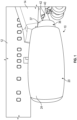
FIG. 1 is a partial side view of an aircraft including a cooling system for a tail cone mounted generator, in accordance with a non-limiting example; -
FIG. 2 depicts a cross-sectional side view of an engine of the aircraft ofFIG. 1 including the cooling system for a tail cone mounted generator, in accordance with a non-limiting example; -
FIG. 3 depicts a cross-sectional side view of a tail cone mounted generator including a cooling system, in accordance with a non-limiting example; -
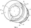
FIG. 4 depicts an axial end view of the tail cone mounted generator supported in an engine housing without the tail cone, in accordance with a non-limiting example; -
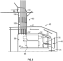
FIG. 5 is a schematic partial side view of a tail cone mounted generator including a cooling system in accordance with another non-limiting example; and -
FIG. 6 depicts a cross-sectional side view of a tail cone mounted generator including a cooling system, in accordance with yet another non-limiting example. - A detailed description of one or more embodiments of the disclosed apparatus and method are presented herein by way of exemplification and not limitation with reference to the Figures.
- An aircraft, in accordance with a non-limiting example, is indicated generally at 10 in
FIG. 1 .Aircraft 10 includes afuselage 12 that supports awing 14. Anengine system 20 including anacelle 24 is supported bywing 14. Nacelle 24 surrounds and protectsengine system 20. At this point, it should be understood thatengine system 20 may also be directly supported byfuselage 12 or be mounted to tail surfaces (not shown) ofaircraft 10. Referring toFIG. 2 , and with continued reference toFIG. 1 ,engine system 20 includes aturbine engine 28 supported withinnacelle 24.Turbine engine 28 includes ahigh pressure spool 30 connected to alow pressure spool 32. A low pressure spool shaft 34 extends fromlow pressure spool 32. Anengine duct 36 including anouter surface section 37 and aninner surface section 38 extends aboutturbine engine 28 and provides a pathway for air flow. - In a non-limiting example,
turbine engine 28 includes atail cone 40 having anouter surface 42 and aninner surface 44. Agenerator housing 48 is arranged withintail cone 40. Referring toFIG. 3 ,generator housing 48 takes the form of a service frame (not separately labeled) having a firstouter surface portion 52 and a firstinner surface portion 54. A secondouter surface portion 55 is spaced from firstinner surface portion 54. A secondinner surface portion 56 extends about agenerator 58 - In a non-limiting example,
generator 58 includes astator 63 including a stator winding (not separately labeled) supported by secondinner surface portion 56. Arotor 65 including a rotor winding (also not separately labeled) is supported on ashaft 67 withinstator 63.Shaft 67 is supported ingenerator housing 48 through afirst bearing 69 and asecond bearing 71.Generator 58 is also shown to include asecondary stator 74 axially spaced fromstator 63. Asecond rotor 76 is supported onshaft 67 axially spaced fromrotor 65 and is rotatable withinsecondary stator 74. - A
first air duct 80 extends from withingenerator housing 48.First air duct 80 includes afirst end 82 positioned inwardly of secondinner surface portion 56 and a second end 84 (FIG. 2 ) that is positioned outwardly ofengine duct 36 as shown inFIG. 2 .First air duct 80 extends through generator housing,tail cone 40 andengine duct 36 withsecond end 84 being exposed to an air stream passing overturbine engine 28. That is,second end 84 offirst air duct 80 includes anopening 86 that faces a first direction and defines an inlet (not separately labeled) that receives air flowing overturbine engine 28. The air passes throughfirst air duct 80 and intogenerator housing 48. The air passes betweenrotor 65 andstator 63 as well as overstator 63. The air also passes betweensecondary stator 74 andsecond rotor 76. In a non-limiting example, portions offirst air duct 80 that extend betweentail cone 40 andengine duct 36 may include an aerodynamic profile as shown inFIG. 4 . - In a non-limiting example, a
second air duct 92 may extend from withingenerator housing 48.Second air duct 92 includes afirst end section 96 that may be positioned between firstouter surface portion 52 ofgenerator housing 48 andinner surface 44 oftail cone 40 and asecond end section 98 that is arranged outwardly ofengine duct 36.Second end section 98 includes an opening 100 (FIG. 2 ) that faces a second direction opposite to that of opening 86 and defines an outlet. In this manner, air that has exchanged heat with internal components ofgenerator 58 may be expelled intotail cone 40, throughsecond air duct 92, and into an airstream passing overturbine engine 28. At this point, it should be understood that the number, orientation, and circumferential location of air ducts may vary. - In a non-limiting example depicted in
FIG. 5 , wherein like reference numbers represent corresponding parts in the respective views,first air duct 80 is shown to also act as a conduit 108 that carrieselectrical conductors 109 from a first terminal block (not shown) positioned ongenerator housing 48 to a second terminal block (also not shown) that may be arranged innacelle 24 and orwing 14.FIG. 6 depicts agenerator housing 48 in which air passes not only betweenstator 63/rotor 65 andsecondary stator 74/second rotor 79 but also throughrotor 65 andsecond rotor 76 in order to further improve cooling. There may be rotor cooling channels formed in rotor lamination for air to flow through the rotor and provide cooling. - The terminology used herein is for the purpose of describing particular embodiments only and is not intended to be limiting of the present disclosure. As used herein, the singular forms "a", "an" and "the" are intended to include the plural forms as well, unless the context clearly indicates otherwise. It will be further understood that the terms "comprises" and/or "comprising," when used in this specification, specify the presence of stated features, integers, steps, operations, elements, and/or components, but do not preclude the presence or addition of one or more other features, integers, steps, operations, element components, and/or groups thereof.
Claims (9)
- An engine system comprising:a high pressure spool;a low pressure spool connected to the high pressure spool;an engine duct (36) extending about the high pressure spool and the low pressure spool, the engine duct including an outer surface section exposed to an external airstream;a tail cone (40) arranged radially inwardly of the engine duct, the tail cone having an outer surface (42) and an inner surface (44);a generator housing (48) arranged in the tail cone, the generator housing including an outer surface portion (52) spaced from the inner surface of the tail cone;a generator (58) mounted in the generator housing and driven by the low pressure spool; andan air duct (80) extending from the generator, through the generator housing, through the tail cone, and through the engine duct, the air duct including a first end (82) arranged in the tail cone and a second end (84) projecting outwardly of the outer surface section of the engine duct aft of the low pressure spool, the second end including an opening (86) exposed to the external air stream passing over the engine duct.
- The engine system according to claim 1, further comprising: another air duct (92) extending from the generator (58), through the generator housing (48), through the tail cone (40), and through the engine duct, the another air duct (92) including another opening exposed to an air stream passing over the engine duct (36); and optionally wherein: the air duct comprises an inlet duct for directing an air flow into the generator housing and the another air duct comprises an outlet air duct for directing the air flow out from the generator housing.
- The engine system according to claim 1 or 2, further comprising: a plenum defined between the outer surface portion (52) of the generator housing (48) and the inner surface (44) of the tail cone (40) and optionally wherein the outlet duct is fluidically connected to the plenum.
- The engine system according to claim 3, wherein the generator (58) includes a drive shaft connectable to the low pressure spool (32) of the engine system the drive shaft having a hollow interior fluidically connected to the plenum through an outlet passage.
- The engine system according to any of claims 2 to 4, wherein the opening (86) of the air duct (80) faces a first direction relative to the engine duct and the another opening of the another air duct faces a second direction that is distinct from the first direction; and optionally
wherein the first direction is directly opposite the second direction. - The engine system according to any preceding claim, further comprising: a plurality of electrical conductors connected to the generator (58), the plurality of electrical conductors pass from the generator through the air duct (80).
- An aircraft comprising:a fuselage (12);a wing (14) supported by the fuselage;an engine system (20) according to any preceding claim supported by the fuselage, the engine system including a nacelle (24) surrounding an engine.
- The aircraft according to claim 7, wherein the engine system (20) is supported in the nacelle (24), the nacelle being mounted to the fuselage (12).
- The aircraft according to claim 7 or 8, wherein the wing (14) is fixedly mounted to the fuselage (12).
Applications Claiming Priority (1)
| Application Number | Priority Date | Filing Date | Title |
|---|---|---|---|
| US17/529,625 US11821370B2 (en) | 2021-11-18 | 2021-11-18 | Cooling system for tail cone mounted generator |
Publications (2)
| Publication Number | Publication Date |
|---|---|
| EP4183996A1 EP4183996A1 (en) | 2023-05-24 |
| EP4183996B1 true EP4183996B1 (en) | 2025-02-12 |
Family
ID=84331986
Family Applications (1)
| Application Number | Title | Priority Date | Filing Date |
|---|---|---|---|
| EP22200961.5A Active EP4183996B1 (en) | 2021-11-18 | 2022-10-11 | Cooling system for tail cone mounted generator |
Country Status (2)
| Country | Link |
|---|---|
| US (1) | US11821370B2 (en) |
| EP (1) | EP4183996B1 (en) |
Families Citing this family (2)
| Publication number | Priority date | Publication date | Assignee | Title |
|---|---|---|---|---|
| US12264623B1 (en) * | 2024-01-18 | 2025-04-01 | Honeywell International Inc. | System for electric machine associated with gas turbine engine |
| US12372010B1 (en) | 2024-01-26 | 2025-07-29 | Rtx Corporation | Passive ventilation system for tail cone zone |
Family Cites Families (9)
| Publication number | Priority date | Publication date | Assignee | Title |
|---|---|---|---|---|
| US8729751B2 (en) * | 2010-11-10 | 2014-05-20 | Hamilton Sundstrand Corporation | Heat transfer assembly for electric motor rotor |
| US9003811B2 (en) | 2011-11-28 | 2015-04-14 | Pratt & Whitney Canada Corp. | Support for electric machine in a turbine engine |
| US9194330B2 (en) * | 2012-07-31 | 2015-11-24 | United Technologies Corporation | Retrofitable auxiliary inlet scoop |
| US9097134B2 (en) | 2012-09-14 | 2015-08-04 | Pratt & Whitney Canada Corp. | Air cooling design for tail-cone generator installation |
| US10208676B2 (en) * | 2016-03-29 | 2019-02-19 | General Electric Company | Gas turbine engine dual sealing cylindrical variable bleed valve |
| US10801410B2 (en) * | 2018-04-12 | 2020-10-13 | Raytheon Technologies Corporation | Thermal management of tail cone mounted generator |
| JP7143904B2 (en) * | 2019-02-13 | 2022-09-29 | 株式会社Ihi | Cooling system for aircraft gas turbine engine |
| WO2021014667A1 (en) * | 2019-07-24 | 2021-01-28 | 株式会社Ihi | Generator cooling system of turbo fan engine |
| US11637475B2 (en) | 2020-03-09 | 2023-04-25 | Hamilton Sundstrand Corporation | Terminal block for integrated tail cone and mounted generator |
-
2021
- 2021-11-18 US US17/529,625 patent/US11821370B2/en active Active
-
2022
- 2022-10-11 EP EP22200961.5A patent/EP4183996B1/en active Active
Also Published As
| Publication number | Publication date |
|---|---|
| US20230151771A1 (en) | 2023-05-18 |
| US11821370B2 (en) | 2023-11-21 |
| EP4183996A1 (en) | 2023-05-24 |
Similar Documents
| Publication | Publication Date | Title |
|---|---|---|
| CN108725804B (en) | Propulsion system for an aircraft | |
| EP2409919B1 (en) | Ram air fan motor cooling | |
| CN108368852B (en) | Electric centrifugal compressors for turbine engines or aircraft | |
| US9287747B2 (en) | Wind power generator with internal cooling circuit | |
| EP3176408A1 (en) | Intercooling system and method for a gas turbine engine | |
| US10823067B2 (en) | System for a surface cooler with OGV oriented fin angles | |
| EP3764523B1 (en) | Electric machine with integrated cooling system | |
| JP2017125499A (en) | System and method of reducing post-shutdown engine temperatures | |
| EP4019784B1 (en) | Cabin air compressor with liquid cooled passage formed in the case | |
| EP4183996B1 (en) | Cooling system for tail cone mounted generator | |
| EP3628598B1 (en) | Power converter cooling | |
| EP4019785B1 (en) | Cabin air compressor with liquid cooled jacket | |
| CN114909222B (en) | Gas turbine engine including embedded electric machine and associated cooling system | |
| EP3176409A1 (en) | Closed loop cooling method for a gas turbine engine | |
| CN114915101B (en) | Electric motors for integration into propulsion engines | |
| US11255215B2 (en) | Gas turbine engine with microchannel cooled electric device | |
| EP3633162B1 (en) | Jet engine heat exchanger system | |
| EP4287464A1 (en) | Rotor assembly for an electrical machine | |
| EP3550149B1 (en) | Structurally improved ram fan inlet shroud | |
| CN120638698A (en) | Motor with cooling feature | |
| CN120601656A (en) | Stator for electric motor | |
| US20260005582A1 (en) | Cooling assembly for electric machine | |
| US20110221288A1 (en) | System and method for cooling in electric machines | |
| CN121932286A (en) | Power transmission system | |
| CN118442184A (en) | Turbine engine including a transfer gearbox and an accessory gearbox |
Legal Events
| Date | Code | Title | Description |
|---|---|---|---|
| PUAI | Public reference made under article 153(3) epc to a published international application that has entered the european phase |
Free format text: ORIGINAL CODE: 0009012 |
|
| STAA | Information on the status of an ep patent application or granted ep patent |
Free format text: STATUS: THE APPLICATION HAS BEEN PUBLISHED |
|
| AK | Designated contracting states |
Kind code of ref document: A1 Designated state(s): AL AT BE BG CH CY CZ DE DK EE ES FI FR GB GR HR HU IE IS IT LI LT LU LV MC ME MK MT NL NO PL PT RO RS SE SI SK SM TR |
|
| STAA | Information on the status of an ep patent application or granted ep patent |
Free format text: STATUS: REQUEST FOR EXAMINATION WAS MADE |
|
| 17P | Request for examination filed |
Effective date: 20231121 |
|
| RBV | Designated contracting states (corrected) |
Designated state(s): AL AT BE BG CH CY CZ DE DK EE ES FI FR GB GR HR HU IE IS IT LI LT LU LV MC ME MK MT NL NO PL PT RO RS SE SI SK SM TR |
|
| GRAP | Despatch of communication of intention to grant a patent |
Free format text: ORIGINAL CODE: EPIDOSNIGR1 |
|
| STAA | Information on the status of an ep patent application or granted ep patent |
Free format text: STATUS: GRANT OF PATENT IS INTENDED |
|
| INTG | Intention to grant announced |
Effective date: 20240911 |
|
| GRAS | Grant fee paid |
Free format text: ORIGINAL CODE: EPIDOSNIGR3 |
|
| GRAA | (expected) grant |
Free format text: ORIGINAL CODE: 0009210 |
|
| STAA | Information on the status of an ep patent application or granted ep patent |
Free format text: STATUS: THE PATENT HAS BEEN GRANTED |
|
| AK | Designated contracting states |
Kind code of ref document: B1 Designated state(s): AL AT BE BG CH CY CZ DE DK EE ES FI FR GB GR HR HU IE IS IT LI LT LU LV MC ME MK MT NL NO PL PT RO RS SE SI SK SM TR |
|
| REG | Reference to a national code |
Ref country code: GB Ref legal event code: FG4D |
|
| REG | Reference to a national code |
Ref country code: CH Ref legal event code: EP |
|
| REG | Reference to a national code |
Ref country code: DE Ref legal event code: R096 Ref document number: 602022010438 Country of ref document: DE |
|
| REG | Reference to a national code |
Ref country code: IE Ref legal event code: FG4D |
|
| REG | Reference to a national code |
Ref country code: NL Ref legal event code: MP Effective date: 20250212 |
|
| PG25 | Lapsed in a contracting state [announced via postgrant information from national office to epo] |
Ref country code: RS Free format text: LAPSE BECAUSE OF FAILURE TO SUBMIT A TRANSLATION OF THE DESCRIPTION OR TO PAY THE FEE WITHIN THE PRESCRIBED TIME-LIMIT Effective date: 20250512 |
|
| PG25 | Lapsed in a contracting state [announced via postgrant information from national office to epo] |
Ref country code: FI Free format text: LAPSE BECAUSE OF FAILURE TO SUBMIT A TRANSLATION OF THE DESCRIPTION OR TO PAY THE FEE WITHIN THE PRESCRIBED TIME-LIMIT Effective date: 20250212 |
|
| PG25 | Lapsed in a contracting state [announced via postgrant information from national office to epo] |
Ref country code: PL Free format text: LAPSE BECAUSE OF FAILURE TO SUBMIT A TRANSLATION OF THE DESCRIPTION OR TO PAY THE FEE WITHIN THE PRESCRIBED TIME-LIMIT Effective date: 20250212 |
|
| PG25 | Lapsed in a contracting state [announced via postgrant information from national office to epo] |
Ref country code: ES Free format text: LAPSE BECAUSE OF FAILURE TO SUBMIT A TRANSLATION OF THE DESCRIPTION OR TO PAY THE FEE WITHIN THE PRESCRIBED TIME-LIMIT Effective date: 20250212 |
|
| REG | Reference to a national code |
Ref country code: LT Ref legal event code: MG9D |
|
| PG25 | Lapsed in a contracting state [announced via postgrant information from national office to epo] |
Ref country code: IS Free format text: LAPSE BECAUSE OF FAILURE TO SUBMIT A TRANSLATION OF THE DESCRIPTION OR TO PAY THE FEE WITHIN THE PRESCRIBED TIME-LIMIT Effective date: 20250612 Ref country code: NO Free format text: LAPSE BECAUSE OF FAILURE TO SUBMIT A TRANSLATION OF THE DESCRIPTION OR TO PAY THE FEE WITHIN THE PRESCRIBED TIME-LIMIT Effective date: 20250512 |
|
| PG25 | Lapsed in a contracting state [announced via postgrant information from national office to epo] |
Ref country code: NL Free format text: LAPSE BECAUSE OF FAILURE TO SUBMIT A TRANSLATION OF THE DESCRIPTION OR TO PAY THE FEE WITHIN THE PRESCRIBED TIME-LIMIT Effective date: 20250212 |
|
| PG25 | Lapsed in a contracting state [announced via postgrant information from national office to epo] |
Ref country code: HR Free format text: LAPSE BECAUSE OF FAILURE TO SUBMIT A TRANSLATION OF THE DESCRIPTION OR TO PAY THE FEE WITHIN THE PRESCRIBED TIME-LIMIT Effective date: 20250212 |
|
| PG25 | Lapsed in a contracting state [announced via postgrant information from national office to epo] |
Ref country code: PT Free format text: LAPSE BECAUSE OF FAILURE TO SUBMIT A TRANSLATION OF THE DESCRIPTION OR TO PAY THE FEE WITHIN THE PRESCRIBED TIME-LIMIT Effective date: 20250612 Ref country code: LV Free format text: LAPSE BECAUSE OF FAILURE TO SUBMIT A TRANSLATION OF THE DESCRIPTION OR TO PAY THE FEE WITHIN THE PRESCRIBED TIME-LIMIT Effective date: 20250212 |
|
| PG25 | Lapsed in a contracting state [announced via postgrant information from national office to epo] |
Ref country code: BG Free format text: LAPSE BECAUSE OF FAILURE TO SUBMIT A TRANSLATION OF THE DESCRIPTION OR TO PAY THE FEE WITHIN THE PRESCRIBED TIME-LIMIT Effective date: 20250212 Ref country code: GR Free format text: LAPSE BECAUSE OF FAILURE TO SUBMIT A TRANSLATION OF THE DESCRIPTION OR TO PAY THE FEE WITHIN THE PRESCRIBED TIME-LIMIT Effective date: 20250513 |
|
| REG | Reference to a national code |
Ref country code: AT Ref legal event code: MK05 Ref document number: 1766232 Country of ref document: AT Kind code of ref document: T Effective date: 20250212 |
|
| PG25 | Lapsed in a contracting state [announced via postgrant information from national office to epo] |
Ref country code: SE Free format text: LAPSE BECAUSE OF FAILURE TO SUBMIT A TRANSLATION OF THE DESCRIPTION OR TO PAY THE FEE WITHIN THE PRESCRIBED TIME-LIMIT Effective date: 20250212 |
|
| PG25 | Lapsed in a contracting state [announced via postgrant information from national office to epo] |
Ref country code: SM Free format text: LAPSE BECAUSE OF FAILURE TO SUBMIT A TRANSLATION OF THE DESCRIPTION OR TO PAY THE FEE WITHIN THE PRESCRIBED TIME-LIMIT Effective date: 20250212 |
|
| PG25 | Lapsed in a contracting state [announced via postgrant information from national office to epo] |
Ref country code: DK Free format text: LAPSE BECAUSE OF FAILURE TO SUBMIT A TRANSLATION OF THE DESCRIPTION OR TO PAY THE FEE WITHIN THE PRESCRIBED TIME-LIMIT Effective date: 20250212 |
|
| PG25 | Lapsed in a contracting state [announced via postgrant information from national office to epo] |
Ref country code: IT Free format text: LAPSE BECAUSE OF FAILURE TO SUBMIT A TRANSLATION OF THE DESCRIPTION OR TO PAY THE FEE WITHIN THE PRESCRIBED TIME-LIMIT Effective date: 20250212 |
|
| PG25 | Lapsed in a contracting state [announced via postgrant information from national office to epo] |
Ref country code: AT Free format text: LAPSE BECAUSE OF FAILURE TO SUBMIT A TRANSLATION OF THE DESCRIPTION OR TO PAY THE FEE WITHIN THE PRESCRIBED TIME-LIMIT Effective date: 20250212 |
|
| PGFP | Annual fee paid to national office [announced via postgrant information from national office to epo] |
Ref country code: FR Payment date: 20250923 Year of fee payment: 4 |
|
| PG25 | Lapsed in a contracting state [announced via postgrant information from national office to epo] |
Ref country code: EE Free format text: LAPSE BECAUSE OF FAILURE TO SUBMIT A TRANSLATION OF THE DESCRIPTION OR TO PAY THE FEE WITHIN THE PRESCRIBED TIME-LIMIT Effective date: 20250212 Ref country code: CZ Free format text: LAPSE BECAUSE OF FAILURE TO SUBMIT A TRANSLATION OF THE DESCRIPTION OR TO PAY THE FEE WITHIN THE PRESCRIBED TIME-LIMIT Effective date: 20250212 |
|
| PG25 | Lapsed in a contracting state [announced via postgrant information from national office to epo] |
Ref country code: RO Free format text: LAPSE BECAUSE OF FAILURE TO SUBMIT A TRANSLATION OF THE DESCRIPTION OR TO PAY THE FEE WITHIN THE PRESCRIBED TIME-LIMIT Effective date: 20250212 |
|
| PG25 | Lapsed in a contracting state [announced via postgrant information from national office to epo] |
Ref country code: SK Free format text: LAPSE BECAUSE OF FAILURE TO SUBMIT A TRANSLATION OF THE DESCRIPTION OR TO PAY THE FEE WITHIN THE PRESCRIBED TIME-LIMIT Effective date: 20250212 |
|
| REG | Reference to a national code |
Ref country code: DE Ref legal event code: R097 Ref document number: 602022010438 Country of ref document: DE |
|
| PLBE | No opposition filed within time limit |
Free format text: ORIGINAL CODE: 0009261 |
|
| STAA | Information on the status of an ep patent application or granted ep patent |
Free format text: STATUS: NO OPPOSITION FILED WITHIN TIME LIMIT |
|
| 26N | No opposition filed |
Effective date: 20251113 |