EP4183988B1 - Exhaust gas treatment system with mixer - Google Patents
Exhaust gas treatment system with mixer Download PDFInfo
- Publication number
- EP4183988B1 EP4183988B1 EP22207458.5A EP22207458A EP4183988B1 EP 4183988 B1 EP4183988 B1 EP 4183988B1 EP 22207458 A EP22207458 A EP 22207458A EP 4183988 B1 EP4183988 B1 EP 4183988B1
- Authority
- EP
- European Patent Office
- Prior art keywords
- tubular element
- openings
- space
- ats
- edge
- Prior art date
- Legal status (The legal status is an assumption and is not a legal conclusion. Google has not performed a legal analysis and makes no representation as to the accuracy of the status listed.)
- Active
Links
Images

Classifications
-
- F—MECHANICAL ENGINEERING; LIGHTING; HEATING; WEAPONS; BLASTING
- F01—MACHINES OR ENGINES IN GENERAL; ENGINE PLANTS IN GENERAL; STEAM ENGINES
- F01N—GAS-FLOW SILENCERS OR EXHAUST APPARATUS FOR MACHINES OR ENGINES IN GENERAL; GAS-FLOW SILENCERS OR EXHAUST APPARATUS FOR INTERNAL-COMBUSTION ENGINES
- F01N3/00—Exhaust or silencing apparatus having means for purifying, rendering innocuous, or otherwise treating exhaust
- F01N3/08—Exhaust or silencing apparatus having means for purifying, rendering innocuous, or otherwise treating exhaust for rendering innocuous
- F01N3/10—Exhaust or silencing apparatus having means for purifying, rendering innocuous, or otherwise treating exhaust for rendering innocuous by thermal or catalytic conversion of noxious components of exhaust
- F01N3/18—Exhaust or silencing apparatus having means for purifying, rendering innocuous, or otherwise treating exhaust for rendering innocuous by thermal or catalytic conversion of noxious components of exhaust characterised by methods of operation; Control
- F01N3/20—Exhaust or silencing apparatus having means for purifying, rendering innocuous, or otherwise treating exhaust for rendering innocuous by thermal or catalytic conversion of noxious components of exhaust characterised by methods of operation; Control specially adapted for catalytic conversion
- F01N3/206—Adding periodically or continuously substances to exhaust gases for promoting purification, e.g. catalytic material in liquid form, NOx reducing agents
- F01N3/2066—Selective catalytic reduction [SCR]
-
- Y—GENERAL TAGGING OF NEW TECHNOLOGICAL DEVELOPMENTS; GENERAL TAGGING OF CROSS-SECTIONAL TECHNOLOGIES SPANNING OVER SEVERAL SECTIONS OF THE IPC; TECHNICAL SUBJECTS COVERED BY FORMER USPC CROSS-REFERENCE ART COLLECTIONS [XRACs] AND DIGESTS
- Y02—TECHNOLOGIES OR APPLICATIONS FOR MITIGATION OR ADAPTATION AGAINST CLIMATE CHANGE
- Y02A—TECHNOLOGIES FOR ADAPTATION TO CLIMATE CHANGE
- Y02A50/00—TECHNOLOGIES FOR ADAPTATION TO CLIMATE CHANGE in human health protection, e.g. against extreme weather
- Y02A50/20—Air quality improvement or preservation, e.g. vehicle emission control or emission reduction by using catalytic converters
-
- Y—GENERAL TAGGING OF NEW TECHNOLOGICAL DEVELOPMENTS; GENERAL TAGGING OF CROSS-SECTIONAL TECHNOLOGIES SPANNING OVER SEVERAL SECTIONS OF THE IPC; TECHNICAL SUBJECTS COVERED BY FORMER USPC CROSS-REFERENCE ART COLLECTIONS [XRACs] AND DIGESTS
- Y02—TECHNOLOGIES OR APPLICATIONS FOR MITIGATION OR ADAPTATION AGAINST CLIMATE CHANGE
- Y02T—CLIMATE CHANGE MITIGATION TECHNOLOGIES RELATED TO TRANSPORTATION
- Y02T10/00—Road transport of goods or passengers
- Y02T10/10—Internal combustion engine [ICE] based vehicles
- Y02T10/12—Improving ICE efficiencies
Definitions
- the present invention relates to a mixer of an after-treatment system for a vehicle, in particular a vehicle exhaust after-treatment system.
- Diesel vehicles need to treat exhaust gases from the engine before they are released into the environment in order to reduce the level of pollutants such as nitrogen oxides or particulate matter.
- the above-described mixing of DEF and exhaust gas is known to be achieved by providing after-treatment systems which have a large linear extension and in which the DEF injection module comprises a tilted dosing module that injects the DEF solution into a long mixing duct.
- This duct is long in order to provide a volume large enough to ensure proper mixing of the exhaust gases with the DEF solution.
- a long duct increases the size of the ATS in the vehicle.
- dosing modules comprising blade or swirl mixers configured to generate particular swirling motions that help to mix the urea with the exhaust gas flow.
- these designs are particularly expensive and increase pressure drops in the after-treatment system, reducing the engine system performance.
- the object of the present invention is to meet the above requirements in an optimized and cost-effective manner.
- FIGS 1 and 2 show a mixer 1 for an After Treatment Systems (ATS) (not shown in its entirety). Although not illustrated in detail for the sake of brevity, the mixer 1 is housed in a space 2 defined by the ATS system.
- ATS After Treatment Systems
- said space 2 is part of a Selective Catalytic Reduction (SCR) module; optionally, the SCR filter elements can be placed radially around the mixer 1 in said space 2 or axially with respect to the mixer 1 in the space 2.
- SCR Selective Catalytic Reduction
- the external tubular element 5 defines an end portion 3 with a diameter sized to cooperate in contact with the aforementioned duct so as to be integral therewith.
- the internal tubular element 4 has a diameter smaller than the diameter of the external tubular element 5 so that it is housed radially and longitudinally inside it. Furthermore, hence, the internal tubular element 4 has a smaller diameter than the exhaust gas inlet duct.
- the mixer 1 comprises a connecting element 6 configured to connect and join the internal tubular element 4 to the external tubular element 5.
- the inner radial edge 7a is configured to be welded on the first terminal edge 4a of the internal tubular element 4, while the outer radial edge 7b is configured to be planted inside the external tubular element 5.
- the spacer element 8 comprises a ring 9 placed radially between the internal tubular element 4 and the external tubular element 5, optionally with a radial preload between them.
- the ring 9 is in contact with the external tubular element 5 and sized to leave a gap with respect to the internal tubular element 4, and the radial preload is provided by a plurality of bosses 10, e.g., three bosses evenly spaced from one another, extending from the ring 9 in contact with the surface of the internal tubular element 4.
- the ring 9 is placed in proximity to a second terminal edge 4b of the internal tubular element 4 facing a second terminal edge 5b of the external tubular element 5.
- the internal tubular element 4 delimits a space 4' fluidically directly in contact with the exhaust gas inlet duct, whereas the external tubular element delimits a space 5' which can be divided as follows:
- Both the internal tubular element 4 and the external tubular element 5 each define a plurality of openings 13, 14 configured to allow fluid communication between the internal tubular element 4 and the first portion 5a' and between the external tubular element 5 and the space 2, and thus with the SCR.
- the first plurality of openings 13' is located close to the second terminal edge 4b, and preferably the spacer element 8 is longitudinally interposed on said first plurality of openings 13'.
- the second plurality of openings 13" only extends over a circumferential portion of the internal tubular element 4, advantageously over two axially opposite portions.
- the second plurality of openings 13" extends over an angular sector of approximately 90°.
- the external tubular element 5 also defines a first plurality of openings 14' and a second plurality of openings 14".
- both pluralities of openings 14', 14" only extend over a circumferential portion of the external tubular element 5, advantageously over two axially opposite portions.
- these pluralities of openings 14', 14" extend over an angular sector of approximately 90° offset with respect to the second plurality of openings 13" of the internal tubular element 4, i.e., so that these openings do not intersect with each other in the radial direction.
- first and second pluralities of openings 14', 14'' extend along the external tubular element 5 between the longitudinal positions of the first and second inner terminal edges 4a, 4b of the internal annular element 4. Therefore, the first and second inner terminal edges 5a, 5b are spaced from the first and second pluralities of openings 14', 14'' by a space without openings.
- the circumferential extension of the openings of the first plurality of openings 14' in the circumferential direction increases moving away from the second terminal edge 5b.
- the openings of the first plurality of openings 14' are equally spaced from each other.
- the second plurality of openings 14" comprises openings with larger opening section and circular extension than the previous openings of the first plurality of openings 14'.
- these openings are quadrangular, advantageously rectangular in section and are circumferentially equally spaced from each other.
- the DEF mixture from the exhaust gas duct flows into the space 4' parallel to the axis A towards the lid 12.
- a main flow portion F' of the DEF mixture flows directly into the second portion 5b', whereas a bypass flow portion F" flows from the second and first pluralities of openings 14", 14' towards the first portion 5a' of the space 5'.
- the main flow portion F' passes into the third portion 5c' of the space 5', impacting against the shaped surface of the lid 12 and reversing its motion by 180° close to its radial portion 12a, heading towards the first portion 5a' of the space 5'.
- the main flow portion F' mixes with the bypass flow portion F" and exits the first and second pluralities of openings 14', 14", according to their passage section. Once it has flowed into the space 2, the flow continues through the SCR filters allowing the known chemical reduction reactions.
- the labyrinth path provided to the DEF flow which is divided into a main portion and a bypass portion that mix together at two different stages, allows adequate mixing of the DEF flow while preventing high pressure drops.
- the deflector element 7 also makes it possible to give a first acceleration to the flow entering the internal tubular element 4, preventing its direct passage through the portion 5a' of space from the external tubular element.
Landscapes
- Chemical & Material Sciences (AREA)
- Engineering & Computer Science (AREA)
- Chemical Kinetics & Catalysis (AREA)
- Health & Medical Sciences (AREA)
- Toxicology (AREA)
- Combustion & Propulsion (AREA)
- Mechanical Engineering (AREA)
- General Engineering & Computer Science (AREA)
- Exhaust Gas After Treatment (AREA)
Description
- The present invention relates to a mixer of an after-treatment system for a vehicle, in particular a vehicle exhaust after-treatment system.
- Diesel vehicles need to treat exhaust gases from the engine before they are released into the environment in order to reduce the level of pollutants such as nitrogen oxides or particulate matter.
- This treatment is known to be carried out by using exhaust after-treatment systems, also known as After Treatment Systems (ATS), comprising a number of elements such as a Diesel Exhaust Fluid (DEF) solution such as AdBlue®, Diesel Oxidation Catalysts (DOC), Urea Injection Module, Diesel Particulate Filters (DPF), or Selective Catalytic Reduction (SCR); the latter may include multiple intermediate elements such as Selective Catalytic Reduction on Filter (SCRoF) and Clean Up Catalyst (SCR-CUC).
- In these systems it is essential to provide for a proper mixing between urea (injected via dosing modules) and the exhaust gas flow leaving the DOC module before it passes into the SCR in order to generate a gas mixture that allows the chemical reactions of reduction of nitrogen oxides contained in the exhaust gas to take place correctly. In particular, high ammonia uniformity indices (so-called NH3 uniformity indices, NH3 UI) must be provided.
- The above-described mixing of DEF and exhaust gas is known to be achieved by providing after-treatment systems which have a large linear extension and in which the DEF injection module comprises a tilted dosing module that injects the DEF solution into a long mixing duct. This duct is long in order to provide a volume large enough to ensure proper mixing of the exhaust gases with the DEF solution. However, such a long duct increases the size of the ATS in the vehicle.
- Alternatively, it is well known to provide dosing modules comprising blade or swirl mixers configured to generate particular swirling motions that help to mix the urea with the exhaust gas flow. Clearly, these designs are particularly expensive and increase pressure drops in the after-treatment system, reducing the engine system performance.
- In all of the above solutions, it is essential that the DEF urea solution is correctly mixed into the exhaust gas, otherwise the urea may crystallize on the inner walls of the ATS duct; this drawback is due to the fact that the injected urea is at room temperature, i.e., approximately 25 °C, while the exhaust gases are at a temperature of at least 300 °C.
- In view of the above, it is essential to avoid excessive temperature loss in the mixing module because, firstly, the efficiency of the chemical reduction reactions is reduced, and secondly, the possibility of formation of ammonia crystals at high temperature is reduced.
- There is therefore a need to provide a mixing system for an ATS system, which allows proper mixing of the DEF with the exhaust gas flow, thus preventing the formation of deposits, is compact, and does not increase manufacturing costs as well as the pressure drop between the inlet and the outlet of the ATS compared to the known systems.
- Example of mixing systems for an ATS system are disclosed in published documents
WO2017215459 A1 ,EP2984308 A1 orDE102017113357 A1 . - The object of the present invention is to meet the above requirements in an optimized and cost-effective manner.
- Said object is achieved by means of a mixer and an ATS system comprising said mixer as claimed in the appended claims.
- For a better understanding of the present invention, a preferred embodiment is described below by way of nonlimiting example and with reference to the accompanying drawings, wherein:
-
Figure 1 is a perspective view of a mixer of an ATS system according to the invention; -
Figure 2 is an exploded perspective view of the mixer inFigure 1 ; -
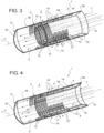
Figure 3 is a perspective, partially sectional view of the mixer inFigure 1 ; and -
Figure 4 is a perspective sectional view of the mixer inFigure 1 . -
Figures 1 and 2 show amixer 1 for an After Treatment Systems (ATS) (not shown in its entirety). Although not illustrated in detail for the sake of brevity, themixer 1 is housed in aspace 2 defined by the ATS system. - In particular, said
space 2 is part of a Selective Catalytic Reduction (SCR) module; optionally, the SCR filter elements can be placed radially around themixer 1 in saidspace 2 or axially with respect to themixer 1 in thespace 2. - In particular, the
mixer 1 is placed downstream of a module (not shown) for the injection of a solution of urea (also known as Diesel Exhaust fluid, in short DEF) with the vehicular exhaust gas flow, preferably connected to an end portion of a duct (not shown). - In particular, the
mixer 1 comprises an internaltubular element 4 configured to be fluidically and directly in series with a duct (not shown), and an externaltubular element 5 configured to house the externaltubular element 4 and be fluidically connected to said duct in series with the internaltubular element 4. - The internal and external
tubular elements - Preferably, the external
tubular element 5 defines anend portion 3 with a diameter sized to cooperate in contact with the aforementioned duct so as to be integral therewith. - The internal
tubular element 4 has a diameter smaller than the diameter of the externaltubular element 5 so that it is housed radially and longitudinally inside it. Furthermore, hence, the internaltubular element 4 has a smaller diameter than the exhaust gas inlet duct. - The
mixer 1 comprises a connecting element 6 configured to connect and join the internaltubular element 4 to the externaltubular element 5. - In particular, the connecting element 6 comprises a
conical ring 7 defining an innerradial edge 7a, of a smaller diameter, sized to cooperate in contact with afirst terminal edge 4a of the internaltubular element 4, and an outerradial edge 7b, of a larger diameter, sized to cooperate in contact with the inner radial surface of the externaltubular element 5, in particular in proximity to afirst terminal edge 5a in the longitudinal direction along the axis A. - In particular, the inner
radial edge 7a is configured to be welded on thefirst terminal edge 4a of the internaltubular element 4, while the outerradial edge 7b is configured to be planted inside the externaltubular element 5. - The
mixer 1 also includes a spacer element 8 configured to keep the internaltubular element 4 and the externaltubular element 5 coaxial with each other. - In particular, the spacer element 8 comprises a
ring 9 placed radially between the internaltubular element 4 and the externaltubular element 5, optionally with a radial preload between them. - In particular, the
ring 9 is in contact with the externaltubular element 5 and sized to leave a gap with respect to the internaltubular element 4, and the radial preload is provided by a plurality ofbosses 10, e.g., three bosses evenly spaced from one another, extending from thering 9 in contact with the surface of the internaltubular element 4. - Preferably, as shown, the
ring 9 is placed in proximity to a secondterminal edge 4b of the internaltubular element 4 facing a secondterminal edge 5b of the externaltubular element 5. - The
mixer 1 further comprises aterminal element 11 configured to be coupled to the secondterminal edge 5b of the externaltubular element 5 to prevent its communication with thespace 2. - In particular, the
terminal element 11 is alid 12 provided with aradial portion 12a configured to cooperate in contact with the externaltubular element 5, advantageously with its inner radial surface, for fastening thelid 12 thereto, and ashaped portion 12b extending from theradial portion 12a externally with respect to the space delimited by the externaltubular element 5. - Preferably, as shown, the
shaped portion 12b has a concave shape facing the externaltubular element 5 and more preferably a spherical sector, where even more preferably the centre of curvature belongs to the axis A. - As a result of the above description, referring to
Figures 3 and 4 , the internaltubular element 4 delimits a space 4' fluidically directly in contact with the exhaust gas inlet duct, whereas the external tubular element delimits a space 5' which can be divided as follows: - a
first portion 5a' having an annular shape and radially delimited between the internal and externaltubular elements - a
second portion 5b' having a cylindrical shape and radially only consisting of the externaltubular element 5 and longitudinally comprised between thesecond terminal edges - a
third portion 5c' having a designed shape, in the case described herein a hemispherical shape radially delimited by thelid 12. - Both the internal
tubular element 4 and the externaltubular element 5 each define a plurality ofopenings tubular element 4 and thefirst portion 5a' and between the externaltubular element 5 and thespace 2, and thus with the SCR. - In particular, the internal
tubular element 4 defines a first plurality of openings 13' and a second plurality ofopenings 13". Preferably, both pluralities ofopenings 13', 13" are circular in shape and have the same diameter. - In greater detail, the first plurality of openings 13' is located close to the second
terminal edge 4b, and preferably the spacer element 8 is longitudinally interposed on said first plurality of openings 13'. - In particular, the first plurality of openings 13' extends circumferentially at 360° with respect to the axis A, i.e., over the entire circumferential extension of the internal
tubular element 4. - The second plurality of
openings 13" extends from the first plurality of openings 13' towards the firstterminal edge 4a. In particular, the second plurality ofopenings 13" extends up to a distance from the firstterminal edge 4a substantially equal to the longitudinal extension of the first plurality of openings 13'. - The second plurality of
openings 13" only extends over a circumferential portion of the internaltubular element 4, advantageously over two axially opposite portions. In particular, the second plurality ofopenings 13" extends over an angular sector of approximately 90°. - Both pluralities of
openings 13', 13" are circumferentially aligned, i.e., the centres of the openings are comprised by circumferences which are advantageously equally spaced along the longitudinal axis A. Moreover, the openings of both pluralities ofopenings 13', 13" are circumferentially equally spaced from each other. - The external
tubular element 5 also defines a first plurality of openings 14' and a second plurality ofopenings 14". In particular, both pluralities ofopenings 14', 14" only extend over a circumferential portion of the externaltubular element 5, advantageously over two axially opposite portions. In particular, these pluralities ofopenings 14', 14" extend over an angular sector of approximately 90° offset with respect to the second plurality ofopenings 13" of the internaltubular element 4, i.e., so that these openings do not intersect with each other in the radial direction. - In particular, the first and second pluralities of openings 14', 14'' extend along the external
tubular element 5 between the longitudinal positions of the first and secondinner terminal edges annular element 4. Therefore, the first and secondinner terminal edges - In greater detail, the first plurality of openings 14' extends further in the longitudinal direction than the second plurality of
openings 14" and faces the secondterminal edge 5b. In particular, these openings 14' are circular in shape and have a variable diameter which increases in size moving away from the secondterminal edge 5b. In particular, the openings furthest away from this edge have a diameter which may be twice as large as those closest to it. - The first plurality of openings 14' comprises openings which are circumferentially aligned, i.e., the centres of the openings are comprised by circumferences spaced apart from each other. This distance advantageously increases moving away from the second
terminal edge 5b. - Furthermore, the circumferential extension of the openings of the first plurality of openings 14' in the circumferential direction increases moving away from the second
terminal edge 5b. Circumferentially, the openings of the first plurality of openings 14' are equally spaced from each other. - The second plurality of
openings 14" comprises openings with larger opening section and circular extension than the previous openings of the first plurality of openings 14'. Advantageously, these openings are quadrangular, advantageously rectangular in section and are circumferentially equally spaced from each other. - The operation of the above-described embodiment of the
mixer 1 according to the invention is as follows. - As shown in
Figure 3 , the DEF mixture from the exhaust gas duct flows into the space 4' parallel to the axis A towards thelid 12. On the other hand, a main flow portion F' of the DEF mixture flows directly into thesecond portion 5b', whereas a bypass flow portion F" flows from the second and first pluralities ofopenings 14", 14' towards thefirst portion 5a' of the space 5'. - As shown in
Figure 4 , the main flow portion F' passes into thethird portion 5c' of the space 5', impacting against the shaped surface of thelid 12 and reversing its motion by 180° close to itsradial portion 12a, heading towards thefirst portion 5a' of the space 5'. - Here, the main flow portion F' mixes with the bypass flow portion F" and exits the first and second pluralities of
openings 14', 14", according to their passage section. Once it has flowed into thespace 2, the flow continues through the SCR filters allowing the known chemical reduction reactions. - The advantages of a mixer for an ATS system according to the invention are clear from the foregoing.
- The
mixer 1 allows high mixing indices for the urea solution in a compact space. - In particular, the labyrinth path provided to the DEF flow, which is divided into a main portion and a bypass portion that mix together at two different stages, allows adequate mixing of the DEF flow while preventing high pressure drops.
- The use of two cylindrical tubular elements makes it possible to use particularly inexpensive and robust elements.
- In addition, the labyrinth path provided and the use of calibrated and angularly offset holes between the internal and external tubular elements make it possible to obtain an extremely compact device.
- The
deflector element 7 also makes it possible to give a first acceleration to the flow entering the internaltubular element 4, preventing its direct passage through theportion 5a' of space from the external tubular element. - The sphere-sector shape of the
lid 12 also allows a 180° change in direction of the DEF flow without excessive turbulence, while maintaining a high mixing flow speed in theportion 5a' of space. - Lastly, it is clear that modifications and variations may be made to the mixer for an ATS system according to the present invention, without however departing from the scope of protection defined by the claims.
- For example, the number and shape of the openings may vary depending on the size of the ATS system, as well as the shape of the lid or of the connecting element.
Claims (18)
- An exhaust gas after-treatment system, ATS, defining a space (2) facing an operating module of said after-treatment system and housing an end portion of a duct, and a module for the injection of a solution of urea into said duct upstream of said space (2), said ATS system comprising a mixer (1) housed within said space (2) and connected to said duct, said mixer (1) housing a mixer (1) according to one of the preceding claims, connected to said duct, said mixer (1) comprising an internal tubular element (4) and an external tubular element (5) extending along a longitudinal axis (A), said external tubular element (5) being sized to delimit a space (5') suitable for housing said internal tubular element (4),said external tubular element (5) comprising a first edge (5a) configured to cooperate in contact with an end portion of said duct and a second edge (5b) opposite to the first along said longitudinal axis (A) configured to separate said space (5') delimited by said external tubular element (5) from said space (2),characterized in that said mixer (1) comprises a connecting element (6) configured to cooperate in contact with said external tubular element (5) and a first edge (4a) of said internal tubular element (4) to allow direct fluid communication only between one space (4') delimited by said internal tubular element (4) and said duct,said internal tubular element (4) defining a plurality of openings (13) configured to allow fluid communication between said space (4') of said internal tubular element (4) and a portion (5a') of said space (5'),said external tubular element (5) defining a plurality of openings (14) configured to allow fluid communication between said portion (5a') of said space (5') and said space (2).
- ATS according to claim 1, wherein said internal tubular element (4) and said external tubular element (5) are coaxial along said longitudinal axis (A).
- ATS according to one of claims 1 or 2, wherein said internal tubular element (4) and said external tubular element (5) are cylindrical.
- ATS according to one of claims 1 to 3, wherein said connecting element (6) comprises a conical ring (7).
- ATS according to one of the preceding claims, further comprising a spacer element (8) configured to keep said internal tubular element (4) and said external tubular element (5) radially separated.
- ATS according to claim 5, wherein said spacer element (8) comprises a ring (9) coaxial with said longitudinal axis (A).
- ATS according to claim 6, wherein said spacer element (8) comprises a plurality of bosses (10) configured to cooperate in contact with radial preload between said internal tubular element (4) and said external tubular element (5).
- ATS according to one of the previous claims, comprising a terminal element (11) cooperating in contact on said second edge (5b) of said external tubular element (5) to separate said space (5') from said space (2).
- ATS according to claim 8, wherein said terminal element (11) comprises a lid (12) comprising a radial portion (12a) configured to cooperate in contact with said external tubular element (5) and a shaped portion (12b) extending externally with respect to said external tubular element (5).
- ATS according to claim 9, wherein said shaped portion (12b) is a sphere portion, where said sphere is centred on said longitudinal axis.
- ATS according to one of the preceding claims, wherein said internal tubular element (4) defines a first plurality of openings (13') and a second plurality of openings (13"), said first plurality of openings (13') being formed in proximity to a second edge (4b), opposite said first edge (4a) along said longitudinal axis, and said second plurality of openings (13") being formed in an intermediate portion between said first plurality of openings (13') and said first edge (4a).
- ATS according to claim 11, wherein said first plurality of openings (13') extends circumferentially entirely around said longitudinal axis (A) and said second plurality of openings (13") extends circumferentially over an angular range around said longitudinal axis (A).
- ATS according to one of the preceding claims, wherein said external tubular element (5) defines a first plurality of openings (14') and a second plurality of openings (14"), said first and second pluralities of openings (14', 14") being made in an intermediate position between said first and second edges (5a, 5b).
- ATS according to claim 13, wherein said first and second pluralities of openings (14', 14") extend circumferentially over an angular range around said longitudinal axis (A).
- ATS according to claim 14, when dependent on claim 12, wherein said angular range of circumferential extension of said first and second pluralities of openings (14', 14") is offset with respect to the angular range of circumferential extension of said second plurality of openings (13") made on said internal tubular element.
- ATS according to one of claims 13 to 15, wherein said first plurality of openings (14') comprises openings having an opening section that increases along said longitudinal axis from said second edge (5b) towards said first edge (5a).
- ATS according to one of claims 13 to 16, wherein said first plurality of openings (14') comprises openings having a longitudinal distance along said axis (A) which varies increasing from said second edge (5b) towards said first edge (5a).
- ATS according to one of claims 13 to 17, wherein said second plurality of openings (14") has a larger opening section than any opening of the first plurality of openings (14').
Applications Claiming Priority (1)
| Application Number | Priority Date | Filing Date | Title |
|---|---|---|---|
| IT102021000029141A IT202100029141A1 (en) | 2021-11-17 | 2021-11-17 | MIXER FOR VEHICLE EXHAUST GAS POST-TREATMENT SYSTEM AND POST-TREATMENT SYSTEM INCLUDING THIS MIXER |
Publications (3)
| Publication Number | Publication Date |
|---|---|
| EP4183988A1 EP4183988A1 (en) | 2023-05-24 |
| EP4183988B1 true EP4183988B1 (en) | 2025-04-09 |
| EP4183988C0 EP4183988C0 (en) | 2025-04-09 |
Family
ID=80461679
Family Applications (1)
| Application Number | Title | Priority Date | Filing Date |
|---|---|---|---|
| EP22207458.5A Active EP4183988B1 (en) | 2021-11-17 | 2022-11-15 | Exhaust gas treatment system with mixer |
Country Status (2)
| Country | Link |
|---|---|
| EP (1) | EP4183988B1 (en) |
| IT (1) | IT202100029141A1 (en) |
Families Citing this family (1)
| Publication number | Priority date | Publication date | Assignee | Title |
|---|---|---|---|---|
| DE102024128324A1 (en) * | 2024-10-01 | 2026-04-02 | Purem GmbH | Mixing section for an exhaust system of an internal combustion engine |
Family Cites Families (3)
| Publication number | Priority date | Publication date | Assignee | Title |
|---|---|---|---|---|
| CN105378245B (en) * | 2013-04-11 | 2018-07-20 | 珀金斯发动机有限公司 | Mixer and emission cleaning module |
| CN107489501A (en) * | 2016-06-13 | 2017-12-19 | 天纳克(苏州)排放系统有限公司 | Exhaust aftertreatment mixing arrangement |
| DE102017113357A1 (en) * | 2017-06-19 | 2018-12-20 | Volkswagen Aktiengesellschaft | Exhaust pipe, internal combustion engine and motor vehicle |
-
2021
- 2021-11-17 IT IT102021000029141A patent/IT202100029141A1/en unknown
-
2022
- 2022-11-15 EP EP22207458.5A patent/EP4183988B1/en active Active
Also Published As
| Publication number | Publication date |
|---|---|
| IT202100029141A1 (en) | 2023-05-17 |
| EP4183988C0 (en) | 2025-04-09 |
| EP4183988A1 (en) | 2023-05-24 |
Similar Documents
| Publication | Publication Date | Title |
|---|---|---|
| US10443477B2 (en) | Counter-swirl mixer | |
| CN217872989U (en) | Mixer and exhaust gas aftertreatment system | |
| US11193412B2 (en) | Automotive exhaust aftertreatment system | |
| US10273855B2 (en) | Exhaust aftertreatment system having mixer assembly | |
| EP2358982B1 (en) | Flow device for an exhaust system | |
| US10960366B2 (en) | Dosing and mixing arrangement for use in exhaust aftertreatment | |
| US8991160B2 (en) | Reductant aqueous solution mixing device and exhaust aftertreatment device provided with the same | |
| US9062589B2 (en) | Reductant aqueous solution mixing device and exhaust aftertreatment device provided with the same | |
| US8460610B2 (en) | Canister aftertreatment module | |
| US20160243510A1 (en) | Dual Auger Mixing System | |
| CN114458425A (en) | Mixer, exhaust system and mixing method | |
| US20170361273A1 (en) | Single module integrated aftertreatment module | |
| CN113803137B (en) | Mixer baffle with integrated sensor | |
| CN110056418B (en) | Exhaust aftertreatment device for box-type engine | |
| EP4183988A1 (en) | Mixer for a vehicular exhaust after-treatment system and after-treatment system comprising such mixer | |
| CN109356693B (en) | Compact mixer assembly | |
| GB2595019A (en) | Systems and methods for mixing exhaust gas and reductant in an exhaust gas aftertreatment system | |
| US20250354512A1 (en) | Aftertreatment system including mixer with exhaust sampling flange | |
| US11519316B2 (en) | Inlet cone and plate assembly for exhaust module | |
| WO2019055922A1 (en) | Exhaust aftertreatment apparatus | |
| KR101427950B1 (en) | Mixer of selective catalyst reduction device for exhaust system | |
| US12492656B2 (en) | Decomposition chambers for aftertreatment systems | |
| CN111742122B (en) | Reducing agent injection device | |
| CN111828142A (en) | Exhaust gas treatment device for an exhaust system of an internal combustion engine | |
| US12359600B2 (en) | Exhaust aftertreatment apparatus |
Legal Events
| Date | Code | Title | Description |
|---|---|---|---|
| PUAI | Public reference made under article 153(3) epc to a published international application that has entered the european phase |
Free format text: ORIGINAL CODE: 0009012 |
|
| STAA | Information on the status of an ep patent application or granted ep patent |
Free format text: STATUS: THE APPLICATION HAS BEEN PUBLISHED |
|
| AK | Designated contracting states |
Kind code of ref document: A1 Designated state(s): AL AT BE BG CH CY CZ DE DK EE ES FI FR GB GR HR HU IE IS IT LI LT LU LV MC ME MK MT NL NO PL PT RO RS SE SI SK SM TR |
|
| STAA | Information on the status of an ep patent application or granted ep patent |
Free format text: STATUS: REQUEST FOR EXAMINATION WAS MADE |
|
| 17P | Request for examination filed |
Effective date: 20231115 |
|
| RBV | Designated contracting states (corrected) |
Designated state(s): AL AT BE BG CH CY CZ DE DK EE ES FI FR GB GR HR HU IE IS IT LI LT LU LV MC ME MK MT NL NO PL PT RO RS SE SI SK SM TR |
|
| STAA | Information on the status of an ep patent application or granted ep patent |
Free format text: STATUS: EXAMINATION IS IN PROGRESS |
|
| 17Q | First examination report despatched |
Effective date: 20240429 |
|
| GRAP | Despatch of communication of intention to grant a patent |
Free format text: ORIGINAL CODE: EPIDOSNIGR1 |
|
| STAA | Information on the status of an ep patent application or granted ep patent |
Free format text: STATUS: GRANT OF PATENT IS INTENDED |
|
| INTG | Intention to grant announced |
Effective date: 20241105 |
|
| GRAS | Grant fee paid |
Free format text: ORIGINAL CODE: EPIDOSNIGR3 |
|
| GRAA | (expected) grant |
Free format text: ORIGINAL CODE: 0009210 |
|
| STAA | Information on the status of an ep patent application or granted ep patent |
Free format text: STATUS: THE PATENT HAS BEEN GRANTED |
|
| AK | Designated contracting states |
Kind code of ref document: B1 Designated state(s): AL AT BE BG CH CY CZ DE DK EE ES FI FR GB GR HR HU IE IS IT LI LT LU LV MC ME MK MT NL NO PL PT RO RS SE SI SK SM TR |
|
| REG | Reference to a national code |
Ref country code: GB Ref legal event code: FG4D |
|
| REG | Reference to a national code |
Ref country code: CH Ref legal event code: EP |
|
| REG | Reference to a national code |
Ref country code: DE Ref legal event code: R096 Ref document number: 602022012853 Country of ref document: DE |
|
| REG | Reference to a national code |
Ref country code: IE Ref legal event code: FG4D |
|
| U01 | Request for unitary effect filed |
Effective date: 20250423 |
|
| U07 | Unitary effect registered |
Designated state(s): AT BE BG DE DK EE FI FR IT LT LU LV MT NL PT RO SE SI Effective date: 20250502 |
|
| PG25 | Lapsed in a contracting state [announced via postgrant information from national office to epo] |
Ref country code: ES Free format text: LAPSE BECAUSE OF FAILURE TO SUBMIT A TRANSLATION OF THE DESCRIPTION OR TO PAY THE FEE WITHIN THE PRESCRIBED TIME-LIMIT Effective date: 20250409 |
|
| PG25 | Lapsed in a contracting state [announced via postgrant information from national office to epo] |
Ref country code: GR Free format text: LAPSE BECAUSE OF FAILURE TO SUBMIT A TRANSLATION OF THE DESCRIPTION OR TO PAY THE FEE WITHIN THE PRESCRIBED TIME-LIMIT Effective date: 20250710 Ref country code: NO Free format text: LAPSE BECAUSE OF FAILURE TO SUBMIT A TRANSLATION OF THE DESCRIPTION OR TO PAY THE FEE WITHIN THE PRESCRIBED TIME-LIMIT Effective date: 20250709 |
|
| PG25 | Lapsed in a contracting state [announced via postgrant information from national office to epo] |
Ref country code: PL Free format text: LAPSE BECAUSE OF FAILURE TO SUBMIT A TRANSLATION OF THE DESCRIPTION OR TO PAY THE FEE WITHIN THE PRESCRIBED TIME-LIMIT Effective date: 20250409 |
|
| PG25 | Lapsed in a contracting state [announced via postgrant information from national office to epo] |
Ref country code: HR Free format text: LAPSE BECAUSE OF FAILURE TO SUBMIT A TRANSLATION OF THE DESCRIPTION OR TO PAY THE FEE WITHIN THE PRESCRIBED TIME-LIMIT Effective date: 20250409 |
|
| PG25 | Lapsed in a contracting state [announced via postgrant information from national office to epo] |
Ref country code: RS Free format text: LAPSE BECAUSE OF FAILURE TO SUBMIT A TRANSLATION OF THE DESCRIPTION OR TO PAY THE FEE WITHIN THE PRESCRIBED TIME-LIMIT Effective date: 20250709 |
|
| PG25 | Lapsed in a contracting state [announced via postgrant information from national office to epo] |
Ref country code: IS Free format text: LAPSE BECAUSE OF FAILURE TO SUBMIT A TRANSLATION OF THE DESCRIPTION OR TO PAY THE FEE WITHIN THE PRESCRIBED TIME-LIMIT Effective date: 20250809 |
|
| U20 | Renewal fee for the european patent with unitary effect paid |
Year of fee payment: 4 Effective date: 20251003 |
|
| PG25 | Lapsed in a contracting state [announced via postgrant information from national office to epo] |
Ref country code: SM Free format text: LAPSE BECAUSE OF FAILURE TO SUBMIT A TRANSLATION OF THE DESCRIPTION OR TO PAY THE FEE WITHIN THE PRESCRIBED TIME-LIMIT Effective date: 20250409 |
|
| PG25 | Lapsed in a contracting state [announced via postgrant information from national office to epo] |
Ref country code: CZ Free format text: LAPSE BECAUSE OF FAILURE TO SUBMIT A TRANSLATION OF THE DESCRIPTION OR TO PAY THE FEE WITHIN THE PRESCRIBED TIME-LIMIT Effective date: 20250409 |
|
| PG25 | Lapsed in a contracting state [announced via postgrant information from national office to epo] |
Ref country code: SK Free format text: LAPSE BECAUSE OF FAILURE TO SUBMIT A TRANSLATION OF THE DESCRIPTION OR TO PAY THE FEE WITHIN THE PRESCRIBED TIME-LIMIT Effective date: 20250409 |
|
| PLBE | No opposition filed within time limit |
Free format text: ORIGINAL CODE: 0009261 |
|
| STAA | Information on the status of an ep patent application or granted ep patent |
Free format text: STATUS: NO OPPOSITION FILED WITHIN TIME LIMIT |
|
| REG | Reference to a national code |
Ref country code: CH Ref legal event code: L10 Free format text: ST27 STATUS EVENT CODE: U-0-0-L10-L00 (AS PROVIDED BY THE NATIONAL OFFICE) Effective date: 20260218 |
|
| 26N | No opposition filed |
Effective date: 20260112 |