EP4183981A1 - Airfoil, gas turbine engine and investment casting core - Google Patents
Airfoil, gas turbine engine and investment casting core Download PDFInfo
- Publication number
- EP4183981A1 EP4183981A1 EP22208282.8A EP22208282A EP4183981A1 EP 4183981 A1 EP4183981 A1 EP 4183981A1 EP 22208282 A EP22208282 A EP 22208282A EP 4183981 A1 EP4183981 A1 EP 4183981A1
- Authority
- EP
- European Patent Office
- Prior art keywords
- airfoil
- section
- platform
- core
- recited
- Prior art date
- Legal status (The legal status is an assumption and is not a legal conclusion. Google has not performed a legal analysis and makes no representation as to the accuracy of the status listed.)
- Pending
Links
Images



Classifications
-
- F—MECHANICAL ENGINEERING; LIGHTING; HEATING; WEAPONS; BLASTING
- F01—MACHINES OR ENGINES IN GENERAL; ENGINE PLANTS IN GENERAL; STEAM ENGINES
- F01D—NON-POSITIVE DISPLACEMENT MACHINES OR ENGINES, e.g. STEAM TURBINES
- F01D5/00—Blades; Blade-carrying members; Heating, heat-insulating, cooling or antivibration means on the blades or the members
- F01D5/12—Blades
- F01D5/14—Form or construction
- F01D5/18—Hollow blades, i.e. blades with cooling or heating channels or cavities; Heating, heat-insulating or cooling means on blades
- F01D5/187—Convection cooling
-
- F—MECHANICAL ENGINEERING; LIGHTING; HEATING; WEAPONS; BLASTING
- F01—MACHINES OR ENGINES IN GENERAL; ENGINE PLANTS IN GENERAL; STEAM ENGINES
- F01D—NON-POSITIVE DISPLACEMENT MACHINES OR ENGINES, e.g. STEAM TURBINES
- F01D5/00—Blades; Blade-carrying members; Heating, heat-insulating, cooling or antivibration means on the blades or the members
- F01D5/12—Blades
- F01D5/14—Form or construction
- F01D5/18—Hollow blades, i.e. blades with cooling or heating channels or cavities; Heating, heat-insulating or cooling means on blades
-
- F—MECHANICAL ENGINEERING; LIGHTING; HEATING; WEAPONS; BLASTING
- F01—MACHINES OR ENGINES IN GENERAL; ENGINE PLANTS IN GENERAL; STEAM ENGINES
- F01D—NON-POSITIVE DISPLACEMENT MACHINES OR ENGINES, e.g. STEAM TURBINES
- F01D5/00—Blades; Blade-carrying members; Heating, heat-insulating, cooling or antivibration means on the blades or the members
- F01D5/12—Blades
- F01D5/14—Form or construction
- F01D5/141—Shape, i.e. outer, aerodynamic form
- F01D5/142—Shape, i.e. outer, aerodynamic form of the blades of successive rotor or stator blade-rows
- F01D5/143—Contour of the outer or inner working fluid flow path wall, i.e. shroud or hub contour
-
- F—MECHANICAL ENGINEERING; LIGHTING; HEATING; WEAPONS; BLASTING
- F01—MACHINES OR ENGINES IN GENERAL; ENGINE PLANTS IN GENERAL; STEAM ENGINES
- F01D—NON-POSITIVE DISPLACEMENT MACHINES OR ENGINES, e.g. STEAM TURBINES
- F01D5/00—Blades; Blade-carrying members; Heating, heat-insulating, cooling or antivibration means on the blades or the members
- F01D5/12—Blades
- F01D5/14—Form or construction
- F01D5/18—Hollow blades, i.e. blades with cooling or heating channels or cavities; Heating, heat-insulating or cooling means on blades
- F01D5/186—Film cooling
-
- F—MECHANICAL ENGINEERING; LIGHTING; HEATING; WEAPONS; BLASTING
- F05—INDEXING SCHEMES RELATING TO ENGINES OR PUMPS IN VARIOUS SUBCLASSES OF CLASSES F01-F04
- F05D—INDEXING SCHEME FOR ASPECTS RELATING TO NON-POSITIVE-DISPLACEMENT MACHINES OR ENGINES, GAS-TURBINES OR JET-PROPULSION PLANTS
- F05D2220/00—Application
- F05D2220/30—Application in turbines
- F05D2220/32—Application in turbines in gas turbines
-
- F—MECHANICAL ENGINEERING; LIGHTING; HEATING; WEAPONS; BLASTING
- F05—INDEXING SCHEMES RELATING TO ENGINES OR PUMPS IN VARIOUS SUBCLASSES OF CLASSES F01-F04
- F05D—INDEXING SCHEME FOR ASPECTS RELATING TO NON-POSITIVE-DISPLACEMENT MACHINES OR ENGINES, GAS-TURBINES OR JET-PROPULSION PLANTS
- F05D2230/00—Manufacture
- F05D2230/20—Manufacture essentially without removing material
- F05D2230/21—Manufacture essentially without removing material by casting
-
- F—MECHANICAL ENGINEERING; LIGHTING; HEATING; WEAPONS; BLASTING
- F05—INDEXING SCHEMES RELATING TO ENGINES OR PUMPS IN VARIOUS SUBCLASSES OF CLASSES F01-F04
- F05D—INDEXING SCHEME FOR ASPECTS RELATING TO NON-POSITIVE-DISPLACEMENT MACHINES OR ENGINES, GAS-TURBINES OR JET-PROPULSION PLANTS
- F05D2240/00—Components
- F05D2240/20—Rotors
- F05D2240/30—Characteristics of rotor blades, i.e. of any element transforming dynamic fluid energy to or from rotational energy and being attached to a rotor
- F05D2240/304—Characteristics of rotor blades, i.e. of any element transforming dynamic fluid energy to or from rotational energy and being attached to a rotor related to the trailing edge of a rotor blade
-
- F—MECHANICAL ENGINEERING; LIGHTING; HEATING; WEAPONS; BLASTING
- F05—INDEXING SCHEMES RELATING TO ENGINES OR PUMPS IN VARIOUS SUBCLASSES OF CLASSES F01-F04
- F05D—INDEXING SCHEME FOR ASPECTS RELATING TO NON-POSITIVE-DISPLACEMENT MACHINES OR ENGINES, GAS-TURBINES OR JET-PROPULSION PLANTS
- F05D2240/00—Components
- F05D2240/80—Platforms for stationary or moving blades
- F05D2240/81—Cooled platforms
-
- F—MECHANICAL ENGINEERING; LIGHTING; HEATING; WEAPONS; BLASTING
- F05—INDEXING SCHEMES RELATING TO ENGINES OR PUMPS IN VARIOUS SUBCLASSES OF CLASSES F01-F04
- F05D—INDEXING SCHEME FOR ASPECTS RELATING TO NON-POSITIVE-DISPLACEMENT MACHINES OR ENGINES, GAS-TURBINES OR JET-PROPULSION PLANTS
- F05D2250/00—Geometry
- F05D2250/30—Arrangement of components
- F05D2250/32—Arrangement of components according to their shape
- F05D2250/324—Arrangement of components according to their shape divergent
-
- F—MECHANICAL ENGINEERING; LIGHTING; HEATING; WEAPONS; BLASTING
- F05—INDEXING SCHEMES RELATING TO ENGINES OR PUMPS IN VARIOUS SUBCLASSES OF CLASSES F01-F04
- F05D—INDEXING SCHEME FOR ASPECTS RELATING TO NON-POSITIVE-DISPLACEMENT MACHINES OR ENGINES, GAS-TURBINES OR JET-PROPULSION PLANTS
- F05D2260/00—Function
- F05D2260/20—Heat transfer, e.g. cooling
-
- Y—GENERAL TAGGING OF NEW TECHNOLOGICAL DEVELOPMENTS; GENERAL TAGGING OF CROSS-SECTIONAL TECHNOLOGIES SPANNING OVER SEVERAL SECTIONS OF THE IPC; TECHNICAL SUBJECTS COVERED BY FORMER USPC CROSS-REFERENCE ART COLLECTIONS [XRACs] AND DIGESTS
- Y02—TECHNOLOGIES OR APPLICATIONS FOR MITIGATION OR ADAPTATION AGAINST CLIMATE CHANGE
- Y02T—CLIMATE CHANGE MITIGATION TECHNOLOGIES RELATED TO TRANSPORTATION
- Y02T50/00—Aeronautics or air transport
- Y02T50/60—Efficient propulsion technologies, e.g. for aircraft
Definitions
- a gas turbine engine typically includes a fan section, a compressor section, a combustor section and a turbine section. Air entering the compressor section is compressed and delivered into the combustion section where it is mixed with fuel and ignited to generate a high-speed exhaust gas flow. The high-speed exhaust gas flow expands through the turbine section to drive the compressor and the fan section.
- the compressor section typically includes low and high pressure compressors, and the turbine section includes low and high pressure turbines.
- the high pressure turbine drives the high pressure compressor through an outer shaft to form a high spool
- the low pressure turbine drives the low pressure compressor through an inner shaft to form a low spool.
- the fan section may also be driven by the low inner shaft.
- a direct drive gas turbine engine includes a fan section driven by the low spool such that the low pressure compressor, low pressure turbine and fan section rotate at a common speed in a common direction.
- An airfoil according to an example of the present disclosure includes a platform, and an airfoil section that extends from the platform and defines leading and trailing ends and suction and pressure sides.
- the airfoil section has a transition region through which the airfoil section blends into the platform.
- the trailing end of the airfoil section has an axial cooling slot that opens through the transition region and defines an circumferentially diverging ramp in the transition region.
- the circumferentially diverging ramp is radially open.
- the circumferentially diverging ramp is radially sloped.
- the circumferentially diverging ramp has first and second circumferential edges and a radial floor there between that is bowed from the first circumferential edge to the second circumferential edge.
- the platform defines a core gas path surface, and the radial floor is radially offset from the core gas path surface.
- the platform defines a platform trailing end
- the circumferentially diverging ramp has first and second circumferential edges that diverge from each other toward the platform trailing end.
- the airfoil section includes a barrier coating on the circumferentially diverging ramp, and wherein the axial cooling slot with the barrier coating is non-metering for cooling flow there from.
- the circumferentially diverging ramp is radially open and radially sloped.
- the platform defines a platform trailing end
- the circumferentially diverging ramp has first and second circumferential edges that diverge from each other toward the platform trailing end.
- the circumferentially diverging ramp has a radial floor between the first and second circumferential edges that is bowed from the first circumferential edge to the second circumferential edge.
- the transition region does not have any inflection points, is tangent to both the surface of the airfoil section, and is also tangent to a gas path surface on the platform.
- a gas turbine engine includes a compressor section, a combustor in fluid communication with the compressor section, and a turbine section in fluid communication with the combustor.
- the turbine section has airfoils as in any of the foregoing embodiments.
- the circumferentially diverging ramp is radially open.
- the circumferentially diverging ramp is radially sloped.
- the circumferentially diverging ramp has first and second circumferential edges and a radial floor there between that is bowed from the first circumferential edge to the second circumferential edge.
- the platform defines a core gas path surface, and the radial floor is radially inboard of the core gas path surface.
- the platform defines a platform trailing end
- the circumferentially diverging ramp has first and second circumferential edges that diverge from each other toward the platform trailing end.
- the airfoil section includes a barrier coating on the circumferentially diverging ramp, and wherein the axial cooling slot with the barrier coating is non-metering for cooling flow there from.
- An investment casting core includes a refractory core body for investment casting an air airfoil that has a platform and airfoil section that extends from the platform and defines leading and trailing ends and suction and pressure sides.
- the airfoil section has a transition region through which the airfoil section blends into the platform.
- the trailing end of the airfoil section has an axial cooling slot that opens through the transition region and defines a circumferentially diverging ramp in the transition region.
- the core body includes a core body trailing edge that has an enlarged lobe that is configured to form the circumferentially diverging ramp.
- the enlarged lobe is enlarged in a circumferential direction.
- the present disclosure may include any one or more of the individual features disclosed above and/or below alone or in any combination thereof.
- FIG. 1 schematically illustrates a gas turbine engine 20.
- the gas turbine engine 20 is disclosed herein as a two-spool turbofan that generally incorporates a fan section 22, a compressor section 24, a combustor section 26 and a turbine section 28.
- the fan section 22 drives air along a bypass flow path B in a bypass duct defined within a housing 15 such as a fan case or nacelle, and also drives air along a core gas path C for compression and communication into the combustor section 26 then expansion through the turbine section 28.
- the exemplary engine 20 generally includes a low speed spool 30 and a high speed spool 32 mounted for rotation about an engine central longitudinal axis A relative to an engine static structure 36 via several bearing systems 38. It should be understood that various bearing systems 38 at various locations may alternatively or additionally be provided, and the location of bearing systems 38 may be varied as appropriate to the application.
- the low speed spool 30 generally includes an inner shaft 40 that interconnects, a first (or low) pressure compressor 44 and a first (or low) pressure turbine 46.
- the inner shaft 40 is connected to the fan 42 through a speed change mechanism, which in exemplary gas turbine engine 20 is illustrated as a geared architecture 48 to drive a fan 42 at a lower speed than the low speed spool 30.
- the high speed spool 32 includes an outer shaft 50 that interconnects a second (or high) pressure compressor 52 and a second (or high) pressure turbine 54.
- a combustor 56 is arranged in the exemplary gas turbine 20 between the high pressure compressor 52 and the high pressure turbine 54.
- a mid-turbine frame 57 of the engine static structure 36 may be arranged generally between the high pressure turbine 54 and the low pressure turbine 46.
- the mid-turbine frame 57 further supports bearing systems 38 in the turbine section 28.
- the inner shaft 40 and the outer shaft 50 are concentric and rotate via bearing systems 38 about the engine central longitudinal axis A which is collinear with their longitudinal axes.
- the core airflow is compressed by the low pressure compressor 44 then the high pressure compressor 52, mixed and burned with fuel in the combustor 56, then expanded through the high pressure turbine 54 and low pressure turbine 46.
- the mid-turbine frame 57 includes airfoils 59 that are in the core gas path C.
- the turbines 46, 54 rotationally drive the respective low speed spool 30 and high speed spool 32 in response to the expansion.
- gear system 48 may be located aft of the low pressure compressor, or aft of the combustor section 26 or even aft of turbine section 28, and fan 42 may be positioned forward or aft of the location of gear system 48.
- the engine 20 in one example is a high-bypass geared aircraft engine.
- the engine 20 bypass ratio is greater than about six (6), with an example embodiment being greater than about ten (10), and can be less than or equal to about 18.0, or more narrowly can be less than or equal to 16.0.
- the geared architecture 48 is an epicyclic gear train, such as a planetary gear system or other gear system, with a gear reduction ratio of greater than about 2.3.
- the gear reduction ratio may be less than or equal to 4.0.
- the low pressure turbine 46 has a pressure ratio that is greater than about five.
- the low pressure turbine pressure ratio can be less than or equal to 13.0, or more narrowly less than or equal to 12.0.
- the engine 20 bypass ratio is greater than about ten (10:1)
- the fan diameter is significantly larger than that of the low pressure compressor 44
- the low pressure turbine 46 has a pressure ratio that is greater than about five 5:1.
- Low pressure turbine 46 pressure ratio is pressure measured prior to an inlet of low pressure turbine 46 as related to the pressure at the outlet of the low pressure turbine 46 prior to an exhaust nozzle.
- the geared architecture 48 may be an epicycle gear train, such as a planetary gear system or other gear system, with a gear reduction ratio of greater than about 2.3:1 and less than about 5:1. It should be understood, however, that the above parameters are only exemplary of one embodiment of a geared architecture engine and that the present invention is applicable to other gas turbine engines including direct drive turbofans.
- the fan section 22 of the engine 20 is designed for a particular flight condition -- typically cruise at about 0.8 Mach and about 35,000 feet (10,668 meters).
- the flight condition of 0.8 Mach and 35,000 ft (10,668 meters), with the engine at its best fuel consumption - also known as "bucket cruise Thrust Specific Fuel Consumption ('TSFC')" - is the industry standard parameter of lbm of fuel being burned divided by lbf of thrust the engine produces at that minimum point.
- 'TSFC' Thrust Specific Fuel Consumption
- “Low fan pressure ratio” is the pressure ratio across the fan blade alone, without a Fan Exit Guide Vane (“FEGV”) system.
- the low fan pressure ratio as disclosed herein according to one non-limiting embodiment is less than about 1.45, or more narrowly greater than or equal to 1.25.
- Low corrected fan tip speed is the actual fan tip speed in ft/sec divided by an industry standard temperature correction of [(Tram °R) / (518.7 °R)] 0.5 .
- the "Low corrected fan tip speed" as disclosed herein according to one non-limiting embodiment is less than about 1150.0 ft / second (350.5 meters/second), and can be greater than or equal to 1000.0 ft / second (304.8 meters/second).
- FIG. 2 illustrates an example airfoil 60 from the turbine section 28 of the engine 20.
- the airfoil 60 provides examples of several potential manufacturing scenarios that are related to, and form a basis of, this disclosure.
- the airfoil 60 is depicted as a blade, but it is to be understood that the examples herein are also applicable to vanes.
- the airfoil includes a platform 62 and an airfoil section 64 that extends from the platform.
- the platform 62 defines a core gas path surface 62a that serves to bound a portion of the core gas path C of the engine 20.
- the airfoil section 64 includes leading and trailing ends 64a/64b and suction and pressure sides 64c/64d.
- An internal cooling passage 66 in the airfoil section 64 receives cooling (bleed) air from the compressor section 24 of the engine 20.
- the trailing end 64b of the airfoil section 64 includes axial cooling slots 68 that are connected with the cooling passage 66.
- the axial cooling slots 68 extend through the trailing end 64b and serve as exits for the cooling air to be discharged from the cooling passage 66 into the core gas path C.
- the axial cooling slot 68 may i) extend through the circumferential mid-line of the trailing end 64b and open at the trailing edge, ii) extend circumferentially and open at the pressure side 64d near the trailing edge, or iii) open in a conjoined matter at the pressure side 64d and trailing edge.
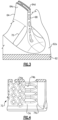
- Figure 3 shows a portion of the airfoil 60 from the region indicated in Figure 2 .
- the airfoil 64 has a transition region 70 through which the airfoil 64 blends into the platform 62.
- the transition region 70 may be or may include what is known as the fillet region.
- the transition region 70 is a curved-surface region that does not have any inflection points (points where there is an inversion in direction of curvature), is tangent on one end to the aerodynamic surface of the airfoil 64, and is also tangent on its other end to the gas path surface 62a.
- the transition region 70 Rather than a continuance of the aerodynamic surface of the airfoil 64 and the gas path surface 62a to meet at a corner, the transition region 70 provides a soft blend between the aerodynamic surface of the airfoil 64 and the gas path surface 62a. As shown, at least one of the axial cooling slots 68 opens through the transition region 70.
- the airfoil 60 is formed of a metal alloy, such as a Ni- or Co-based superalloy, and is fabricated by investment casting. For instance, in investment casting, a refractory metal or ceramic investment core is arranged in a mold and coated with a wax material, which ultimately defines the geometry of the airfoil 60. The wax material is then coated with another material, such as a metallic or ceramic slurry that is hardened into a shell. The wax is melted out of the shell and molten metal is then poured into the cavity that remains between the shell and the core. The metal solidifies around the core to form the airfoil. The core is then removed in a known manner, leaving internal passages within the airfoil.
- a metal alloy such as a Ni- or Co-based superalloy
- Figure 4 illustrates a representative portion of an example investment core 72 for forming the internal cooling passage 66 and axial cooling slots 68 in the airfoil 60.
- the investment core 72 represents a negative of the cooling passage 66 and axial cooling slots 68 in which solid structures of the investment core 72 produce void structures in the airfoil 60 and void structures of the investment core 72 produce solid structures in the airfoil 60.
- the investment core 72 includes a refractory metal or ceramic core body 74.
- the core body 74 includes pedestal openings 74a for forming pedestals in the internal cooling passage 66 and teardrop openings 74b for forming teardrop features that radially bound and define the axial cooling slots 68.
- the investment core 72 may alternatively or additionally include other openings and geometries depending on the particular design of the airfoil 60 for its desired end use performance.
- Aft of the teardrop openings 74b the trailing end portion of the investment core 72 includes an oversize region 74c, the function of which will be described in more detail below.
- the relative position of the investment core 72 in the wax 76 (and thus also the relative position of the cooling passage 66 and axial cooling slots 68 in the airfoil 60) is subject to tolerances of the tooling and techniques that are used.
- the actual position of the investment core 72 and the actual position of the wax 76 can differ from their nominal design positions.
- the investment core 72 may be radially-outwardly displaced such that it is a radial distance D1 above the surface 76a of the wax 76 (which corresponds to the gas path surface 62a in the final airfoil 60).
- the investment core 72 may be radially-inwardly displaced such that it is a radial distance D2 below the surface 76a of the wax 76.
- the metal encases the trailing end of the refractory casting core 72, i.e., the oversize region 74c. Therefore, the axial cooling slots 68 of the airfoil 60 are initially closed-off after casting. A portion of the metal that encases the oversize region 74c is then machined back in order to open the axial cooling slots 68.
- the truncated axial cooling slot 68 leaves a dead-ended pocket 68a in the transition region 70.
- the dead-ended pocket 68a i) may collect grind chips during manufacturing that are difficult to remove and ii) has relatively sharp edges that may collect debris during operation.
- the opening may be of such small size that it is filled by coating material in subsequent processes to deposit a barrier coating on the airfoil 60. Accordingly, in either of the instances above, the relative displacement of the investment core 72 may lead to undesired features in the final airfoil 60.
- the machining of the airfoil 60 may be limited by the grind wheel sizing and accessibility to the area. In general, relatively small grind wheels have lower life, produce rougher finished surfaces, require higher operator skill, increase "touch" time, and challenge consistent repeatable finished geometry.
- a buffer distance is maintained between the nominal design position of the refractory casting core 72 and the gas path surface 62a so that even if the core 72 is displaced inwardly it is still radially above the core gas path surface 62a.
- the buffer distance provides space to envelope the core 72 in wax with sufficient transition to allow for proper molten metal to fill in the trailing edge core slip envelope, represented by region 74c, without the need to hand finish the transition region 70 and thus enable a constant repeatable product.
- the mitigation may be more effective on relatively large airfoils where the tolerances are a relatively small fraction of the trailing edge radial length.
- the tolerances are a relatively small fraction of the trailing edge radial length.
- This may be exacerbated on dual gas-path vanes where the reduction in cooled trailing edge exit is doubled.
- Such compromises may take two forms. The first involves hand finishing the entire interface with a grinding belt, resulting in a higher geometric variability that may affect geometric accuracy of the region.
- the second involves CNC grinding or electric discharge machining to consistently cut the trailing edge within tolerances just above the gas path and apply the standard break edges.
- Figure 9 illustrates an airfoil 160 that, in comparison to the airfoil 60, has a geometry that accounts for core position tolerance during casting and thus enables greater repeatability in manufacturing.
- the airfoil 160 includes axial cooling slots 168.
- the radially inner-most one of the axial cooling slots 168 opens through the transition region 70 and defines a circumferentially diverging ramp 180 in the transition region 70.
- the ramp 180 is defined by first and second circumferential edges 180a/180b that diverge from each other toward a platform trailing end 62b before converging to a rounded ramp trailing edge 180c.
- the ramp 180 has a radial floor 180d that is bowed from the first circumferential edge 180a to the second circumferential edge 180b.
- the radial floor 180d is radially sloped toward the platform trailing end 62b, and at least a portion of the radial floor 180d is radially inboard of the core gas path surface 62a.
- the top i.e. the radially outer plane from the first circumferential edge 180a to the second circumferential edge 180b, is radially open.
- the airfoil 160 may further include a barrier coating 181, such as but not limited to a stabilized zirconia coating.
- the axial cooling slot 168 and ramp 180 are of sufficient size to prevent plugging by the coating 181 and thereby ensure that the slot 168 remains non-metering. That is, if a substantial amount of coating material plugs a slot, the flow area of the slot may be reduced to an extent at which it restricts outflow.
- the ramp 180 mitigates the effects of variations in the relative position of the axial cooling slots 168 relative to the gas path surface 62a.
- the ramp 180 may also facilitate a smooth flow of cooling air from the axial cooling slot 168 into the core gas path C due to the bowing and floor slope, a reduction in metal mass in the transition region 70, an increase in surface area (e.g., via the radial floor 180d), and an increase in the area of the axial cooling slot 168 to reduce the possibility that a later-applied coating plugs the slot 168 and to allow ejection of debris particles from the airfoil 160.
- the divergent geometry of the ramp 180 may also facilitate access to clean out any grinding chips that may settle into the slot 168.
- Figure 10 illustrates the investment core 172 that is configured to form the axial cooling slot 168 and ramp 180.
- the investment core 172 is similar to the above-described core 72 in that it also includes a core body 174 with pedestal openings 174a and teardrop openings 174b.
- the radially inner section of the oversize region 174c includes an enlarged lobe 174d that is configured to form the circumferentially diverging ramp 180.
- the enlarged lobe 174d is enlarged in the circumferential direction and extends farther aft in the axial direction (both relative to engine central longitudinal axis A).
- the cross-sectional area of the oversize region 174c through the lobe 174d taken in a plane parallel to the engine central longitudinal axis A increases from the location RO along the radially inward direction to a location L1.
- the cross-sectional area of the lobe 174d is at its maximum at L1 and then decreases a remainder of the radial inner distance of the oversize region 174d and through an elbow location L2, at which point the edge of the core 172 curves forward beyond the radial plane of the location RO.
- Figure 11 illustrates the investment core 172 enveloped in wax 76, with the trailing end 64b and transition region 70 of the final airfoil 160 superimposed thereon.
- the metal that encases the oversize region 174c is machined back in order to open the axial cooling slots 168, the plane of the machining will cut through the region that corresponds to the lobe 174d, thereby also opening the circumferentially diverging ramp 180.
- the geometry of the ramp 180 thus correspond to the profile of the lobe 174d.
- the size of the lobe 174d in terms of the locations RO and L2 is at least equal to, but is preferably larger than, the maximum tolerance that the position of the core 172 can vary with respect to the gas path surface 62a.
- the machined plane will cut through the region that corresponds to the lobe 174d. This assures that the circumferentially diverging ramp 180, with its desirable geometry, will be opened during machining, rather than the highly variable geometry that results from core position variation for airfoil 60.
- the lobe 174d begins to radially decrease and circumferentially widen within the prescribed diffusion area flow area changes of the other axial cooling slots 168. This is a change in geometry which maintains a consistency of flow area that begins just after the aft most metering location of the axial cooling slot 168.
- the metering area is defined by the minimum cross-sectional area between trailing edge features, and the diffusion area is defined as the region between the metering location and the trailing edge of the trailing edge internal features.
- the lobe 174d continues to widen and ramp toward and beyond the gas path to a degree that will account for any possible coating material that is deposited onto the ramp 180 and ensure that any radial movement of the investment core relative to the wax will produce an acceptable and repeatable trailing edge exit geometry.
- Figure 12 schematically illustrates an investment casting tool 100 that may be used in a molding process to form the refractory casting core 172 disclosed herein.
- the casting tool 100 is formed of a metal alloy and may contain a hard-facing or other protective surface to reduce wear and erosion.
- the tool 100 includes a molding cavity 101.
- the molding cavity 101 is shown as an inverse view, e.g., the refractory casting core as represented and described in Figure 10 .
- the molding cavity 101 thus has the attributes of the core as described herein.
Landscapes
- Engineering & Computer Science (AREA)
- Mechanical Engineering (AREA)
- General Engineering & Computer Science (AREA)
- Physics & Mathematics (AREA)
- Fluid Mechanics (AREA)
- Turbine Rotor Nozzle Sealing (AREA)
- Molds, Cores, And Manufacturing Methods Thereof (AREA)
Abstract
Description
- A gas turbine engine typically includes a fan section, a compressor section, a combustor section and a turbine section. Air entering the compressor section is compressed and delivered into the combustion section where it is mixed with fuel and ignited to generate a high-speed exhaust gas flow. The high-speed exhaust gas flow expands through the turbine section to drive the compressor and the fan section. The compressor section typically includes low and high pressure compressors, and the turbine section includes low and high pressure turbines.
- The high pressure turbine drives the high pressure compressor through an outer shaft to form a high spool, and the low pressure turbine drives the low pressure compressor through an inner shaft to form a low spool. The fan section may also be driven by the low inner shaft. A direct drive gas turbine engine includes a fan section driven by the low spool such that the low pressure compressor, low pressure turbine and fan section rotate at a common speed in a common direction.
- An airfoil according to an example of the present disclosure includes a platform, and an airfoil section that extends from the platform and defines leading and trailing ends and suction and pressure sides. The airfoil section has a transition region through which the airfoil section blends into the platform. The trailing end of the airfoil section has an axial cooling slot that opens through the transition region and defines an circumferentially diverging ramp in the transition region.
- In a further embodiment of any of the foregoing embodiments, the circumferentially diverging ramp is radially open.
- In a further embodiment of any of the foregoing embodiments, the circumferentially diverging ramp is radially sloped.
- In a further embodiment of any of the foregoing embodiments, the circumferentially diverging ramp has first and second circumferential edges and a radial floor there between that is bowed from the first circumferential edge to the second circumferential edge.
- In a further embodiment of any of the foregoing embodiments, the platform defines a core gas path surface, and the radial floor is radially offset from the core gas path surface.
- In a further embodiment of any of the foregoing embodiments, the platform defines a platform trailing end, and the circumferentially diverging ramp has first and second circumferential edges that diverge from each other toward the platform trailing end.
- In a further embodiment of any of the foregoing embodiments, the airfoil section includes a barrier coating on the circumferentially diverging ramp, and wherein the axial cooling slot with the barrier coating is non-metering for cooling flow there from.
- In a further embodiment of any of the foregoing embodiments, the circumferentially diverging ramp is radially open and radially sloped.
- In a further embodiment of any of the foregoing embodiments, the platform defines a platform trailing end, and the circumferentially diverging ramp has first and second circumferential edges that diverge from each other toward the platform trailing end.
- In a further embodiment of any of the foregoing embodiments, the circumferentially diverging ramp has a radial floor between the first and second circumferential edges that is bowed from the first circumferential edge to the second circumferential edge.
- In a further embodiment of any of the foregoing embodiments, the transition region does not have any inflection points, is tangent to both the surface of the airfoil section, and is also tangent to a gas path surface on the platform.
- A gas turbine engine according to an example of the present disclosure includes a compressor section, a combustor in fluid communication with the compressor section, and a turbine section in fluid communication with the combustor. The turbine section has airfoils as in any of the foregoing embodiments.
- In a further embodiment of any of the foregoing embodiments, the circumferentially diverging ramp is radially open.
- In a further embodiment of any of the foregoing embodiments, the circumferentially diverging ramp is radially sloped.
- In a further embodiment of any of the foregoing embodiments, the circumferentially diverging ramp has first and second circumferential edges and a radial floor there between that is bowed from the first circumferential edge to the second circumferential edge.
- In a further embodiment of any of the foregoing embodiments, the platform defines a core gas path surface, and the radial floor is radially inboard of the core gas path surface.
- In a further embodiment of any of the foregoing embodiments, the platform defines a platform trailing end, and the circumferentially diverging ramp has first and second circumferential edges that diverge from each other toward the platform trailing end.
- In a further embodiment of any of the foregoing embodiments, the airfoil section includes a barrier coating on the circumferentially diverging ramp, and wherein the axial cooling slot with the barrier coating is non-metering for cooling flow there from.
- An investment casting core according to an example of the present disclosure includes a refractory core body for investment casting an air airfoil that has a platform and airfoil section that extends from the platform and defines leading and trailing ends and suction and pressure sides. The airfoil section has a transition region through which the airfoil section blends into the platform. The trailing end of the airfoil section has an axial cooling slot that opens through the transition region and defines a circumferentially diverging ramp in the transition region. The core body includes a core body trailing edge that has an enlarged lobe that is configured to form the circumferentially diverging ramp.
- In a further embodiment of any of the foregoing embodiments, the enlarged lobe is enlarged in a circumferential direction.
- The present disclosure may include any one or more of the individual features disclosed above and/or below alone or in any combination thereof.
- The various features and advantages of the present disclosure will become apparent to those skilled in the art from the following detailed description. The drawings that accompany the detailed description can be briefly described as follows.
-
Figure 1 illustrates a gas turbine engine. -
Figure 2 illustrates an airfoil of the engine. -
Figure 3 illustrates a view of a portion of the airfoil ofFigure 2 . -
Figure 4 illustrates an investment casting core for manufacturing the airfoil ofFigure 2 . -
Figure 5 illustrates a relative position of the core embedded in wax. -
Figure 6 illustrates another relative position of the core embedded in wax. -
Figure 7 illustrates the airfoil geometry that results from casting around the core as inFigure 5 . -
Figure 8 illustrates the airfoil geometry that results from casting around the core as inFigure 6 . -
Figure 9 illustrates another example airfoil that has an axially diverging ramp. -
Figure 10 illustrates an investment casting core for manufacturing the airfoil ofFigure 9 . -
Figure 11 illustrates the core ofFigure 10 embedded in wax. -
Figure 12 illustrates a tool for manufacturing the investment casting core ofFigure 10 . -
Figure 1 schematically illustrates agas turbine engine 20. Thegas turbine engine 20 is disclosed herein as a two-spool turbofan that generally incorporates afan section 22, acompressor section 24, acombustor section 26 and aturbine section 28. Thefan section 22 drives air along a bypass flow path B in a bypass duct defined within ahousing 15 such as a fan case or nacelle, and also drives air along a core gas path C for compression and communication into thecombustor section 26 then expansion through theturbine section 28. Although depicted as a two-spool turbofan gas turbine engine in the disclosed non-limiting embodiment, it should be understood that the concepts described herein are not limited to use with two-spool turbofans as the teachings may be applied to other types of turbine engines including three-spool architectures. - The
exemplary engine 20 generally includes alow speed spool 30 and ahigh speed spool 32 mounted for rotation about an engine central longitudinal axis A relative to an enginestatic structure 36 viaseveral bearing systems 38. It should be understood thatvarious bearing systems 38 at various locations may alternatively or additionally be provided, and the location ofbearing systems 38 may be varied as appropriate to the application. - The
low speed spool 30 generally includes aninner shaft 40 that interconnects, a first (or low)pressure compressor 44 and a first (or low)pressure turbine 46. Theinner shaft 40 is connected to thefan 42 through a speed change mechanism, which in exemplarygas turbine engine 20 is illustrated as a gearedarchitecture 48 to drive afan 42 at a lower speed than thelow speed spool 30. Thehigh speed spool 32 includes anouter shaft 50 that interconnects a second (or high)pressure compressor 52 and a second (or high)pressure turbine 54. Acombustor 56 is arranged in theexemplary gas turbine 20 between thehigh pressure compressor 52 and thehigh pressure turbine 54. Amid-turbine frame 57 of the enginestatic structure 36 may be arranged generally between thehigh pressure turbine 54 and thelow pressure turbine 46. Themid-turbine frame 57 further supports bearingsystems 38 in theturbine section 28. Theinner shaft 40 and theouter shaft 50 are concentric and rotate viabearing systems 38 about the engine central longitudinal axis A which is collinear with their longitudinal axes. - The core airflow is compressed by the
low pressure compressor 44 then thehigh pressure compressor 52, mixed and burned with fuel in thecombustor 56, then expanded through thehigh pressure turbine 54 andlow pressure turbine 46. Themid-turbine frame 57 includesairfoils 59 that are in the core gas path C. Theturbines low speed spool 30 andhigh speed spool 32 in response to the expansion. It will be appreciated that each of the positions of thefan section 22,compressor section 24,combustor section 26,turbine section 28, and fandrive gear system 48 may be varied. For example,gear system 48 may be located aft of the low pressure compressor, or aft of thecombustor section 26 or even aft ofturbine section 28, andfan 42 may be positioned forward or aft of the location ofgear system 48. - The
engine 20 in one example is a high-bypass geared aircraft engine. In a further example, theengine 20 bypass ratio is greater than about six (6), with an example embodiment being greater than about ten (10), and can be less than or equal to about 18.0, or more narrowly can be less than or equal to 16.0. The gearedarchitecture 48 is an epicyclic gear train, such as a planetary gear system or other gear system, with a gear reduction ratio of greater than about 2.3. The gear reduction ratio may be less than or equal to 4.0. Thelow pressure turbine 46 has a pressure ratio that is greater than about five. The low pressure turbine pressure ratio can be less than or equal to 13.0, or more narrowly less than or equal to 12.0. In one disclosed embodiment, theengine 20 bypass ratio is greater than about ten (10:1), the fan diameter is significantly larger than that of thelow pressure compressor 44, and thelow pressure turbine 46 has a pressure ratio that is greater than about five 5:1.Low pressure turbine 46 pressure ratio is pressure measured prior to an inlet oflow pressure turbine 46 as related to the pressure at the outlet of thelow pressure turbine 46 prior to an exhaust nozzle. The gearedarchitecture 48 may be an epicycle gear train, such as a planetary gear system or other gear system, with a gear reduction ratio of greater than about 2.3:1 and less than about 5:1. It should be understood, however, that the above parameters are only exemplary of one embodiment of a geared architecture engine and that the present invention is applicable to other gas turbine engines including direct drive turbofans. - A significant amount of thrust is provided by the bypass flow B due to the high bypass ratio. The
fan section 22 of theengine 20 is designed for a particular flight condition -- typically cruise at about 0.8 Mach and about 35,000 feet (10,668 meters). The flight condition of 0.8 Mach and 35,000 ft (10,668 meters), with the engine at its best fuel consumption - also known as "bucket cruise Thrust Specific Fuel Consumption ('TSFC')" - is the industry standard parameter of lbm of fuel being burned divided by lbf of thrust the engine produces at that minimum point. The engine parameters described above and those in this paragraph are measured at this condition unless otherwise specified. "Low fan pressure ratio" is the pressure ratio across the fan blade alone, without a Fan Exit Guide Vane ("FEGV") system. The low fan pressure ratio as disclosed herein according to one non-limiting embodiment is less than about 1.45, or more narrowly greater than or equal to 1.25. "Low corrected fan tip speed" is the actual fan tip speed in ft/sec divided by an industry standard temperature correction of [(Tram °R) / (518.7 °R)]0.5. The "Low corrected fan tip speed" as disclosed herein according to one non-limiting embodiment is less than about 1150.0 ft / second (350.5 meters/second), and can be greater than or equal to 1000.0 ft / second (304.8 meters/second). -
Figure 2 illustrates anexample airfoil 60 from theturbine section 28 of theengine 20. As will be evident from the following description, theairfoil 60 provides examples of several potential manufacturing scenarios that are related to, and form a basis of, this disclosure. Theairfoil 60 is depicted as a blade, but it is to be understood that the examples herein are also applicable to vanes. The airfoil includes aplatform 62 and anairfoil section 64 that extends from the platform. Theplatform 62 defines a core gas path surface 62a that serves to bound a portion of the core gas path C of theengine 20. Theairfoil section 64 includes leading and trailing ends 64a/64b and suction andpressure sides 64c/64d. Aninternal cooling passage 66 in theairfoil section 64 receives cooling (bleed) air from thecompressor section 24 of theengine 20. The trailingend 64b of theairfoil section 64 includesaxial cooling slots 68 that are connected with thecooling passage 66. Theaxial cooling slots 68 extend through the trailingend 64b and serve as exits for the cooling air to be discharged from thecooling passage 66 into the core gas path C. For example, theaxial cooling slot 68 may i) extend through the circumferential mid-line of the trailingend 64b and open at the trailing edge, ii) extend circumferentially and open at thepressure side 64d near the trailing edge, or iii) open in a conjoined matter at thepressure side 64d and trailing edge. -
Figure 3 shows a portion of theairfoil 60 from the region indicated inFigure 2 . Theairfoil 64 has atransition region 70 through which theairfoil 64 blends into theplatform 62. Thetransition region 70 may be or may include what is known as the fillet region. For example, thetransition region 70 is a curved-surface region that does not have any inflection points (points where there is an inversion in direction of curvature), is tangent on one end to the aerodynamic surface of theairfoil 64, and is also tangent on its other end to the gas path surface 62a. Rather than a continuance of the aerodynamic surface of theairfoil 64 and the gas path surface 62a to meet at a corner, thetransition region 70 provides a soft blend between the aerodynamic surface of theairfoil 64 and the gas path surface 62a. As shown, at least one of theaxial cooling slots 68 opens through thetransition region 70. - The
airfoil 60 is formed of a metal alloy, such as a Ni- or Co-based superalloy, and is fabricated by investment casting. For instance, in investment casting, a refractory metal or ceramic investment core is arranged in a mold and coated with a wax material, which ultimately defines the geometry of theairfoil 60. The wax material is then coated with another material, such as a metallic or ceramic slurry that is hardened into a shell. The wax is melted out of the shell and molten metal is then poured into the cavity that remains between the shell and the core. The metal solidifies around the core to form the airfoil. The core is then removed in a known manner, leaving internal passages within the airfoil. -
Figure 4 illustrates a representative portion of anexample investment core 72 for forming theinternal cooling passage 66 andaxial cooling slots 68 in theairfoil 60. Theinvestment core 72 represents a negative of thecooling passage 66 andaxial cooling slots 68 in which solid structures of theinvestment core 72 produce void structures in theairfoil 60 and void structures of theinvestment core 72 produce solid structures in theairfoil 60. Theinvestment core 72 includes a refractory metal orceramic core body 74. In this example, thecore body 74 includespedestal openings 74a for forming pedestals in theinternal cooling passage 66 andteardrop openings 74b for forming teardrop features that radially bound and define theaxial cooling slots 68. As will be appreciated, theinvestment core 72 may alternatively or additionally include other openings and geometries depending on the particular design of theairfoil 60 for its desired end use performance. Aft of theteardrop openings 74b the trailing end portion of theinvestment core 72 includes anoversize region 74c, the function of which will be described in more detail below. - In the investment casting process, the relative position of the
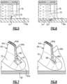
investment core 72 in the wax 76 (and thus also the relative position of thecooling passage 66 andaxial cooling slots 68 in the airfoil 60) is subject to tolerances of the tooling and techniques that are used. For instance, the actual position of theinvestment core 72 and the actual position of thewax 76 can differ from their nominal design positions. As a result, in some instances as represented inFigure 5 , theinvestment core 72 may be radially-outwardly displaced such that it is a radial distance D1 above thesurface 76a of the wax 76 (which corresponds to the gas path surface 62a in the final airfoil 60). In other instances, as represented inFigure 6 , theinvestment core 72 may be radially-inwardly displaced such that it is a radial distance D2 below thesurface 76a of thewax 76. - After the shell is molded around the
wax 76 and the molten metal is poured to form theairfoil 60, the metal encases the trailing end of therefractory casting core 72, i.e., theoversize region 74c. Therefore, theaxial cooling slots 68 of theairfoil 60 are initially closed-off after casting. A portion of the metal that encases theoversize region 74c is then machined back in order to open theaxial cooling slots 68. - In the instance of
Figure 5 where theinvestment core 72 is radially-outwardly displaced, the result is that the radially inner-mostaxial cooling slot 68 is displaced radially outwardly from the gas path surface 62a, which is shown inFigure 7 . In the instance ofFigure 6 where theinvestment core 72 is radially-inwardly displaced, the result is that the radially inner-mostaxial cooling slot 68 is displaced radially inwardly from the gas path surface 62a, which is shown inFigure 8 . In either instance, there may be a detriment to performance and/or manufacturing. For example, in the instance ofFigure 7 , there is a region R1 that is a relatively large mass of solid metal. Such a mass, which is not the design intent, may influence thermal transfer and thus effect airfoil durability. In the instance ofFigure 8 , the truncatedaxial cooling slot 68 leaves a dead-endedpocket 68a in thetransition region 70. The dead-endedpocket 68a i) may collect grind chips during manufacturing that are difficult to remove and ii) has relatively sharp edges that may collect debris during operation. Moreover, even if a portion of thepocket 68a is initially open, the opening may be of such small size that it is filled by coating material in subsequent processes to deposit a barrier coating on theairfoil 60. Accordingly, in either of the instances above, the relative displacement of theinvestment core 72 may lead to undesired features in thefinal airfoil 60. - The machining of the
airfoil 60 may be limited by the grind wheel sizing and accessibility to the area. In general, relatively small grind wheels have lower life, produce rougher finished surfaces, require higher operator skill, increase "touch" time, and challenge consistent repeatable finished geometry. To mitigate at least the scenario ofFigure 5 , a buffer distance is maintained between the nominal design position of therefractory casting core 72 and the gas path surface 62a so that even if thecore 72 is displaced inwardly it is still radially above the core gas path surface 62a. The buffer distance provides space to envelope the core 72 in wax with sufficient transition to allow for proper molten metal to fill in the trailing edge core slip envelope, represented byregion 74c, without the need to hand finish thetransition region 70 and thus enable a constant repeatable product. - The mitigation may be more effective on relatively large airfoils where the tolerances are a relatively small fraction of the trailing edge radial length. However, as the parts become smaller the same tolerances and the minimum wax thickness and transition requirements for proper metal flow become a significant percentage of the trailing edge length. This may be exacerbated on dual gas-path vanes where the reduction in cooled trailing edge exit is doubled. Thus, on smaller parts it is common to run the wax slip envelopment into the gas paths and accept that the area will have major geometric compromises. Such compromises may take two forms. The first involves hand finishing the entire interface with a grinding belt, resulting in a higher geometric variability that may affect geometric accuracy of the region. The second involves CNC grinding or electric discharge machining to consistently cut the trailing edge within tolerances just above the gas path and apply the standard break edges. Although each of these compromises can meet design requirements for the resultant
finished airfoil 60, there are inevitably debits to performance and manufacturing from the geometry variations that must be balanced in a given design. -
Figure 9 illustrates anairfoil 160 that, in comparison to theairfoil 60, has a geometry that accounts for core position tolerance during casting and thus enables greater repeatability in manufacturing. As shown, theairfoil 160 includesaxial cooling slots 168. The radially inner-most one of theaxial cooling slots 168 opens through thetransition region 70 and defines a circumferentially divergingramp 180 in thetransition region 70. Theramp 180 is defined by first and secondcircumferential edges 180a/180b that diverge from each other toward aplatform trailing end 62b before converging to a roundedramp trailing edge 180c. Theramp 180 has aradial floor 180d that is bowed from the firstcircumferential edge 180a to the secondcircumferential edge 180b. Theradial floor 180d is radially sloped toward theplatform trailing end 62b, and at least a portion of theradial floor 180d is radially inboard of the core gas path surface 62a. The top, i.e. the radially outer plane from the firstcircumferential edge 180a to the secondcircumferential edge 180b, is radially open. Theairfoil 160 may further include abarrier coating 181, such as but not limited to a stabilized zirconia coating. However, theaxial cooling slot 168 and ramp 180 are of sufficient size to prevent plugging by thecoating 181 and thereby ensure that theslot 168 remains non-metering. That is, if a substantial amount of coating material plugs a slot, the flow area of the slot may be reduced to an extent at which it restricts outflow. - As will be discussed below, the
ramp 180 mitigates the effects of variations in the relative position of theaxial cooling slots 168 relative to the gas path surface 62a. Theramp 180 may also facilitate a smooth flow of cooling air from theaxial cooling slot 168 into the core gas path C due to the bowing and floor slope, a reduction in metal mass in thetransition region 70, an increase in surface area (e.g., via theradial floor 180d), and an increase in the area of theaxial cooling slot 168 to reduce the possibility that a later-applied coating plugs theslot 168 and to allow ejection of debris particles from theairfoil 160. Additionally, during machining, the divergent geometry of theramp 180 may also facilitate access to clean out any grinding chips that may settle into theslot 168. -
Figure 10 illustrates theinvestment core 172 that is configured to form theaxial cooling slot 168 andramp 180. Theinvestment core 172 is similar to the above-describedcore 72 in that it also includes acore body 174 withpedestal openings 174a andteardrop openings 174b. However, the radially inner section of theoversize region 174c includes anenlarged lobe 174d that is configured to form thecircumferentially diverging ramp 180. For instance, in comparison to the radially outer section of theoversize region 174c (e.g., at location RO), theenlarged lobe 174d is enlarged in the circumferential direction and extends farther aft in the axial direction (both relative to engine central longitudinal axis A). Thus, in the example shown, the cross-sectional area of theoversize region 174c through thelobe 174d taken in a plane parallel to the engine central longitudinal axis A increases from the location RO along the radially inward direction to a location L1. The cross-sectional area of thelobe 174d is at its maximum at L1 and then decreases a remainder of the radial inner distance of theoversize region 174d and through an elbow location L2, at which point the edge of the core 172 curves forward beyond the radial plane of the location RO. -
Figure 11 illustrates theinvestment core 172 enveloped inwax 76, with the trailingend 64b andtransition region 70 of thefinal airfoil 160 superimposed thereon. When the metal that encases theoversize region 174c is machined back in order to open theaxial cooling slots 168, the plane of the machining will cut through the region that corresponds to thelobe 174d, thereby also opening thecircumferentially diverging ramp 180. The geometry of theramp 180 thus correspond to the profile of thelobe 174d. - The size of the
lobe 174d in terms of the locations RO and L2 is at least equal to, but is preferably larger than, the maximum tolerance that the position of the core 172 can vary with respect to the gas path surface 62a. Thus, at any position within the maximum tolerance envelope, the machined plane will cut through the region that corresponds to thelobe 174d. This assures that thecircumferentially diverging ramp 180, with its desirable geometry, will be opened during machining, rather than the highly variable geometry that results from core position variation forairfoil 60. - The
lobe 174d begins to radially decrease and circumferentially widen within the prescribed diffusion area flow area changes of the otheraxial cooling slots 168. This is a change in geometry which maintains a consistency of flow area that begins just after the aft most metering location of theaxial cooling slot 168. The metering area is defined by the minimum cross-sectional area between trailing edge features, and the diffusion area is defined as the region between the metering location and the trailing edge of the trailing edge internal features. Beyond the diffusion region of the trailing edge slot, thelobe 174d continues to widen and ramp toward and beyond the gas path to a degree that will account for any possible coating material that is deposited onto theramp 180 and ensure that any radial movement of the investment core relative to the wax will produce an acceptable and repeatable trailing edge exit geometry. -
Figure 12 schematically illustrates aninvestment casting tool 100 that may be used in a molding process to form therefractory casting core 172 disclosed herein. For example, thecasting tool 100 is formed of a metal alloy and may contain a hard-facing or other protective surface to reduce wear and erosion. Thetool 100 includes amolding cavity 101. In this example, themolding cavity 101 is shown as an inverse view, e.g., the refractory casting core as represented and described inFigure 10 . Themolding cavity 101 thus has the attributes of the core as described herein. - Although a combination of features is shown in the illustrated examples, not all of them need to be combined to realize the benefits of various embodiments of this disclosure. In other words, a system designed according to an embodiment of this disclosure will not necessarily include all of the features shown in any one of the Figures or all of the portions schematically shown in the Figures. Moreover, selected features of one example embodiment may be combined with selected features of other example embodiments.
- The preceding description is exemplary rather than limiting in nature. Variations and modifications to the disclosed examples may become apparent to those skilled in the art that do not necessarily depart from this disclosure. The scope of legal protection given to this disclosure can only be determined by studying the following claims.
Claims (11)
- An airfoil (160) comprising:a platform (62); andan airfoil section (64) extending from the platform (62) and defining leading and trailing ends (64a, 64b) and suction and pressure sides (64c, 64d), the airfoil section (64) having a transition region (70) through which the airfoil section (64) blends into the platform (62), the trailing end (64b) of the airfoil section (64) having an axial cooling slot (168) opening through the transition region (70) and defining a circumferentially diverging ramp (180) in the transition region (70).
- The airfoil (160) as recited in claim 1, wherein the circumferentially diverging ramp (180) is radially open.
- The airfoil (160) as recited in claim 1 or 2, wherein the circumferentially diverging ramp (180) is radially sloped.
- The airfoil (160) as recited in any preceding claim, wherein the circumferentially diverging ramp (180) has first and second circumferential edges (180a, 180b) and a radial floor (180d) therebetween that is bowed from the first circumferential edge (180a) to the second circumferential edge (180b).
- The airfoil (160) as recited in claim 4, wherein the platform (62) defines a core gas path surface (62a), and the radial floor (180d) is radially offset from or inboard of the core gas path surface (62a).
- The airfoil (160) as recited in any preceding claim, wherein the platform (62) defines a platform trailing end, and the circumferentially diverging ramp (180) has first and second circumferential edges (180a, 180b) that diverge from each other toward the platform trailing end.
- The airfoil (160) as recited in any preceding claim, wherein the airfoil section (64) includes a barrier coating (181) on the circumferentially diverging ramp (180), and wherein the axial cooling slot (168) with the barrier coating (181) is non-metering for cooling flow therefrom.
- The airfoil (160) as recited in any preceding claim, wherein the transition region (70) does not have any inflection points, is tangent to both the surface of the airfoil section (64), and is also tangent to a gas path surface (62a) on the platform (62).
- A gas turbine engine (20) comprising:a compressor section (24);a combustor (56) in fluid communication with the compressor section (24); anda turbine section (28) in fluid communication with the combustor (56), the turbine section (28) having airfoils (160) disposed about a central axis (A) of the gas turbine engine (20), each of the airfoils (160) being an airfoil (60) as recited in any preceding claim.
- An investment casting core (172) comprising:a refractory core body (174) for investment casting an air airfoil (160) as recited in any preceding claim,the core body (174) including a core body trailing edge having an enlarged lobe (174d) that is configured to form the circumferentially diverging ramp (180).
- The investment casting core (172) as recited in claim 10, wherein the enlarged lobe (174d) is enlarged in a circumferential direction.
Applications Claiming Priority (2)
| Application Number | Priority Date | Filing Date | Title |
|---|---|---|---|
| US202163281041P | 2021-11-18 | 2021-11-18 | |
| US202263315674P | 2022-03-02 | 2022-03-02 |
Publications (1)
| Publication Number | Publication Date |
|---|---|
| EP4183981A1 true EP4183981A1 (en) | 2023-05-24 |
Family
ID=84360413
Family Applications (1)
| Application Number | Title | Priority Date | Filing Date |
|---|---|---|---|
| EP22208282.8A Pending EP4183981A1 (en) | 2021-11-18 | 2022-11-18 | Airfoil, gas turbine engine and investment casting core |
Country Status (2)
| Country | Link |
|---|---|
| US (1) | US12158083B2 (en) |
| EP (1) | EP4183981A1 (en) |
Families Citing this family (1)
| Publication number | Priority date | Publication date | Assignee | Title |
|---|---|---|---|---|
| US12523178B1 (en) * | 2024-11-25 | 2026-01-13 | General Electric Deutschland Holding Gmbh | Compressor bleed-air boost system |
Citations (3)
| Publication number | Priority date | Publication date | Assignee | Title |
|---|---|---|---|---|
| EP1016773A2 (en) * | 1998-12-30 | 2000-07-05 | ABB Alstom Power (Schweiz) AG | Coolable turbine blade |
| US20080138208A1 (en) * | 2006-12-09 | 2008-06-12 | Rolls-Royce Plc | Core for use in a casting mould |
| US20120076654A1 (en) * | 2010-09-29 | 2012-03-29 | General Electric Company | Turbine airfoil and method for cooling a turbine airfoil |
Family Cites Families (10)
| Publication number | Priority date | Publication date | Assignee | Title |
|---|---|---|---|---|
| US6609891B2 (en) * | 2001-08-30 | 2003-08-26 | General Electric Company | Turbine airfoil for gas turbine engine |
| US6612811B2 (en) * | 2001-12-12 | 2003-09-02 | General Electric Company | Airfoil for a turbine nozzle of a gas turbine engine and method of making same |
| US6599092B1 (en) * | 2002-01-04 | 2003-07-29 | General Electric Company | Methods and apparatus for cooling gas turbine nozzles |
| FR2835015B1 (en) * | 2002-01-23 | 2005-02-18 | Snecma Moteurs | HIGH-PRESSURE TURBINE MOBILE TURBINE WITH IMPROVED THERMAL BEHAVIOR LEAKAGE EDGE |
| FR2864990B1 (en) * | 2004-01-14 | 2008-02-22 | Snecma Moteurs | IMPROVEMENTS IN THE HIGH-PRESSURE TURBINE AIR COOLING AIR EXHAUST DUCTING SLOTS |
| US8827647B1 (en) * | 2010-06-24 | 2014-09-09 | Florida Turbine Technologies, Inc. | Turbine blade with root section cooling |
| US9482100B2 (en) * | 2012-02-15 | 2016-11-01 | United Technologies Corporation | Multi-lobed cooling hole |
| US9186757B2 (en) * | 2012-05-09 | 2015-11-17 | Siemens Energy, Inc. | Method of providing a turbine blade tip repair |
| US10107107B2 (en) * | 2012-06-28 | 2018-10-23 | United Technologies Corporation | Gas turbine engine component with discharge slot having oval geometry |
| WO2014163679A1 (en) * | 2013-03-12 | 2014-10-09 | Uskert Richard C | Ceramic matrix composite airfoil, corresponding apparatus and method |
-
2022
- 2022-11-17 US US17/988,917 patent/US12158083B2/en active Active
- 2022-11-18 EP EP22208282.8A patent/EP4183981A1/en active Pending
Patent Citations (3)
| Publication number | Priority date | Publication date | Assignee | Title |
|---|---|---|---|---|
| EP1016773A2 (en) * | 1998-12-30 | 2000-07-05 | ABB Alstom Power (Schweiz) AG | Coolable turbine blade |
| US20080138208A1 (en) * | 2006-12-09 | 2008-06-12 | Rolls-Royce Plc | Core for use in a casting mould |
| US20120076654A1 (en) * | 2010-09-29 | 2012-03-29 | General Electric Company | Turbine airfoil and method for cooling a turbine airfoil |
Also Published As
| Publication number | Publication date |
|---|---|
| US12158083B2 (en) | 2024-12-03 |
| US20230151737A1 (en) | 2023-05-18 |
Similar Documents
| Publication | Publication Date | Title |
|---|---|---|
| EP3056674B1 (en) | Article having cooling passage with undulating profile | |
| US10406596B2 (en) | Core arrangement for turbine engine component | |
| EP3734018A1 (en) | Seal for a gas turbine engine | |
| EP3170981B1 (en) | An airfoil comprising a baffle, a gas turbine engine, and a method of repairing an airfoil | |
| US10677069B2 (en) | Component core with shaped edges | |
| US9752442B2 (en) | Airfoil with variable profile responsive to thermal conditions | |
| US11111857B2 (en) | Hourglass airfoil cooling configuration | |
| EP3130756A1 (en) | Low turn loss baffle flow diverter | |
| EP3342982B1 (en) | Inclined crossover passages for internal airfoil cavities | |
| EP3578758A1 (en) | Turbine airfoil, corresponding gas turbine engine and method of making | |
| EP3103965B1 (en) | Attachment arrangement for turbine engine blade outer air seal | |
| EP4183981A1 (en) | Airfoil, gas turbine engine and investment casting core | |
| EP3587734A1 (en) | Cooling arrangement with crenellation features for gas turbine engine component | |
| US11008873B2 (en) | Turbine blade tip wall cooling | |
| EP3495616B1 (en) | Airfoil with internal cooling passages | |
| EP3808938B1 (en) | Airfoil component with trailing end margin and cutback | |
| EP3734014B1 (en) | Welding method for hollow airfoils and intermediate body | |
| EP3599346B1 (en) | Airfoil with trailing edge rounding | |
| EP2890878B1 (en) | Blade outer air seal | |
| EP3181863B1 (en) | Gas turbine engine with minimized inlet distortion | |
| EP3495619B1 (en) | Airfoil with internal cooling passages |
Legal Events
| Date | Code | Title | Description |
|---|---|---|---|
| PUAI | Public reference made under article 153(3) epc to a published international application that has entered the european phase |
Free format text: ORIGINAL CODE: 0009012 |
|
| STAA | Information on the status of an ep patent application or granted ep patent |
Free format text: STATUS: THE APPLICATION HAS BEEN PUBLISHED |
|
| AK | Designated contracting states |
Kind code of ref document: A1 Designated state(s): AL AT BE BG CH CY CZ DE DK EE ES FI FR GB GR HR HU IE IS IT LI LT LU LV MC ME MK MT NL NO PL PT RO RS SE SI SK SM TR |
|
| RAP3 | Party data changed (applicant data changed or rights of an application transferred) |
Owner name: RTX CORPORATION |
|
| STAA | Information on the status of an ep patent application or granted ep patent |
Free format text: STATUS: REQUEST FOR EXAMINATION WAS MADE |
|
| 17P | Request for examination filed |
Effective date: 20231120 |
|
| RBV | Designated contracting states (corrected) |
Designated state(s): AL AT BE BG CH CY CZ DE DK EE ES FI FR GB GR HR HU IE IS IT LI LT LU LV MC ME MK MT NL NO PL PT RO RS SE SI SK SM TR |
|
| RIC1 | Information provided on ipc code assigned before grant |
Ipc: F01D 5/14 20060101ALN20231206BHEP Ipc: F01D 5/18 20060101AFI20231206BHEP |
|
| STAA | Information on the status of an ep patent application or granted ep patent |
Free format text: STATUS: EXAMINATION IS IN PROGRESS |
|
| 17Q | First examination report despatched |
Effective date: 20240409 |
|
| RIC1 | Information provided on ipc code assigned before grant |
Ipc: F01D 5/18 20060101AFI20260224BHEP Ipc: F01D 5/14 20060101ALN20260224BHEP |
|
| GRAP | Despatch of communication of intention to grant a patent |
Free format text: ORIGINAL CODE: EPIDOSNIGR1 |
|
| STAA | Information on the status of an ep patent application or granted ep patent |
Free format text: STATUS: GRANT OF PATENT IS INTENDED |
|
| RIC1 | Information provided on ipc code assigned before grant |
Ipc: F01D 5/18 20060101AFI20260319BHEP Ipc: F01D 5/14 20060101ALN20260319BHEP |