EP4183966A1 - Slat for roller shutters, shutter comprising such a slat and plant for manufacturing such a shutter - Google Patents
Slat for roller shutters, shutter comprising such a slat and plant for manufacturing such a shutter Download PDFInfo
- Publication number
- EP4183966A1 EP4183966A1 EP22207672.1A EP22207672A EP4183966A1 EP 4183966 A1 EP4183966 A1 EP 4183966A1 EP 22207672 A EP22207672 A EP 22207672A EP 4183966 A1 EP4183966 A1 EP 4183966A1
- Authority
- EP
- European Patent Office
- Prior art keywords
- slat
- appendage
- elongated body
- coupling
- longitudinal
- Prior art date
- Legal status (The legal status is an assumption and is not a legal conclusion. Google has not performed a legal analysis and makes no representation as to the accuracy of the status listed.)
- Granted
Links
Images




Classifications
-
- E—FIXED CONSTRUCTIONS
- E06—DOORS, WINDOWS, SHUTTERS, OR ROLLER BLINDS IN GENERAL; LADDERS
- E06B—FIXED OR MOVABLE CLOSURES FOR OPENINGS IN BUILDINGS, VEHICLES, FENCES OR LIKE ENCLOSURES IN GENERAL, e.g. DOORS, WINDOWS, BLINDS, GATES
- E06B9/00—Screening or protective devices for wall or similar openings, with or without operating or securing mechanisms; Closures of similar construction
- E06B9/02—Shutters, movable grilles, or other safety closing devices, e.g. against burglary
- E06B9/08—Roll-type closures
- E06B9/11—Roller shutters
- E06B9/15—Roller shutters with closing members formed of slats or the like
-
- E—FIXED CONSTRUCTIONS
- E06—DOORS, WINDOWS, SHUTTERS, OR ROLLER BLINDS IN GENERAL; LADDERS
- E06B—FIXED OR MOVABLE CLOSURES FOR OPENINGS IN BUILDINGS, VEHICLES, FENCES OR LIKE ENCLOSURES IN GENERAL, e.g. DOORS, WINDOWS, BLINDS, GATES
- E06B9/00—Screening or protective devices for wall or similar openings, with or without operating or securing mechanisms; Closures of similar construction
- E06B9/02—Shutters, movable grilles, or other safety closing devices, e.g. against burglary
- E06B9/08—Roll-type closures
- E06B9/11—Roller shutters
- E06B9/15—Roller shutters with closing members formed of slats or the like
- E06B9/165—Roller shutters with closing members formed of slats or the like with slats disappearing in each other; with slats the distance between which can be altered
-
- E—FIXED CONSTRUCTIONS
- E06—DOORS, WINDOWS, SHUTTERS, OR ROLLER BLINDS IN GENERAL; LADDERS
- E06B—FIXED OR MOVABLE CLOSURES FOR OPENINGS IN BUILDINGS, VEHICLES, FENCES OR LIKE ENCLOSURES IN GENERAL, e.g. DOORS, WINDOWS, BLINDS, GATES
- E06B9/00—Screening or protective devices for wall or similar openings, with or without operating or securing mechanisms; Closures of similar construction
- E06B9/02—Shutters, movable grilles, or other safety closing devices, e.g. against burglary
- E06B9/08—Roll-type closures
- E06B9/11—Roller shutters
- E06B9/15—Roller shutters with closing members formed of slats or the like
- E06B2009/1533—Slat connections
- E06B2009/1538—Slats directly connected
- E06B2009/1544—Engaging section has curved articulation surfaces
-
- E—FIXED CONSTRUCTIONS
- E06—DOORS, WINDOWS, SHUTTERS, OR ROLLER BLINDS IN GENERAL; LADDERS
- E06B—FIXED OR MOVABLE CLOSURES FOR OPENINGS IN BUILDINGS, VEHICLES, FENCES OR LIKE ENCLOSURES IN GENERAL, e.g. DOORS, WINDOWS, BLINDS, GATES
- E06B9/00—Screening or protective devices for wall or similar openings, with or without operating or securing mechanisms; Closures of similar construction
- E06B9/02—Shutters, movable grilles, or other safety closing devices, e.g. against burglary
- E06B9/08—Roll-type closures
- E06B9/11—Roller shutters
- E06B9/15—Roller shutters with closing members formed of slats or the like
- E06B2009/1533—Slat connections
- E06B2009/1572—Locking means to prevent slat disengagement
-
- E—FIXED CONSTRUCTIONS
- E06—DOORS, WINDOWS, SHUTTERS, OR ROLLER BLINDS IN GENERAL; LADDERS
- E06B—FIXED OR MOVABLE CLOSURES FOR OPENINGS IN BUILDINGS, VEHICLES, FENCES OR LIKE ENCLOSURES IN GENERAL, e.g. DOORS, WINDOWS, BLINDS, GATES
- E06B9/00—Screening or protective devices for wall or similar openings, with or without operating or securing mechanisms; Closures of similar construction
- E06B9/02—Shutters, movable grilles, or other safety closing devices, e.g. against burglary
- E06B9/08—Roll-type closures
- E06B9/11—Roller shutters
- E06B9/17—Parts or details of roller shutters, e.g. suspension devices, shutter boxes, wicket doors, ventilation openings
- E06B2009/17092—Manufacturing
Definitions
- the present invention relates to a slat for roller shutters, a shutter comprising such a slat and a plant for manufacturing such a shutter.
- a roller shutter for windows and glass doors consists of a plurality of slats which are identical to one another and coupled to one another along respective longitudinal edges.
- the slats are shaped so as to be able to be mutually coupled to one another.
- the coupling zones are configured to allow partial rotation between the slats about the longitudinal direction.
- the roller shutter may roll up on itself. In this way, the shutter may be completely or partially raised or lowered by rolling one or more slats into a suitable container arranged above the window or glass door space, depending upon the opening requirements of the space itself.
- a traditional slat D consists of an elongated body E, in a metal or plastic material, which in use will face the outside of the compartment with a first face E1 (outer face) and towards the inside of the compartment with a second face E2 (inner face).
- the elongated body E comprises a coupling appendage A, extending along the whole of an upper longitudinal edge BS, and a hollow seat C extending along the whole of a lower longitudinal edge BI.
- the hollow seat C is delimited by a first portion C1 arranged on the outer face E1 of the elongated body E and by a second portion C2 of the elongated body, which is arranged on the inner face E2 of the elongated body E and is generally L-shaped.
- the two portions C1 and C2 are connected by a bottom wall C3.
- the hollow seat C and the coupling appendage A are shaped so as to allow mutual coupling.
- the coupling appendage A engages with the L-shaped second portion C2.
- the coupling appendage of a first slat is inserted into the hollow seat of a second slat arranged above, while the hollow seat of this first slat receives therein the coupling appendage of a third slat (not shown) arranged below.
- each slat is open at both longitudinal ends of the slat itself. In this way, one slat may be coupled to another by longitudinally sliding the coupling appendage of one slat inside the hollow seat of the other slat starting at one of the two ends.
- end caps are however expensive insofar as it involves the supply of additional components (the caps) and requires a specific step for the application during the production process of the shutters.
- the hollow seat C to be deformed is a flap of the first portion C1 arranged on the outer face E1 of the elongated body E.
- the flap to be deformed is separated from the rest of the first portion C1 by means of a transverse notch that extends in depth up to the bottom wall C3.
- the same notch also partially affects the second portion C2, limited to the base of the L, in such a way as to implement a separate flap also in this second portion C2.
- the coupling appendage A has been inserted (suitably shaped)
- the aforementioned flap of the first portion C1 engages with the flap of the second portion C2, deforming it in turn.
- the base of the L is bent against the vertical portion of the L. In this way the hollow seat C1 is completely closed. This operation is carried out at both ends of the slat.
- a first drawback is in relation to the fact that if the two coupled slats are rotated in relation to one another by an angle beyond 90°, it may happen that the coupling appendage A is forcibly inserted between the two deformed portions C1 and C2 and may slide out of the hollow seat C, at least partially, thereby compromising the complete functionality of the shutter.
- a second drawback is related to the fact that the deformation of the flap of the first portion C1 modifies the outer face E1 of the elongated body E. This is at the expense of the aesthetic appearance of the slat itself on the most visible side and therefore the value of the same slat.
- the main object of the present invention is to eliminate all or part of the drawbacks of the aforementioned prior art, in providing a roller shutter slat that may be assembled to form a shutter while ensuring a more stable and safe coupling between the coupling appendage and the hollow seat, without at the same time requiring modifications to the external face of the slat itself.
- a further object of this invention is to provide a slat for roller shutters that is simple and cost-effective to produce.
- Figure 20 shows a front orthogonal view of an assembly station of a shutter production plant according to the invention.
- the slat 1 for roller shutters according to the invention has been indicated as a whole by the reference number 1 in the accompanying figures.
- the roller shutter slat 1 comprises an internally hollow elongated body 10, which extends along a longitudinal direction X and comprises a first face 10e and a second face 10i, opposite the first, which in use are designed to be turned respectively towards the outside and inside of the compartment closed by the shutter of which said slat 1 is designed to form a part.
- the elongated body 10 comprises:
- the elongated body 10 consists of a box-shaped body made by bending and profiling a metal sheet.
- the coupling cavity 20 is obtained integrally within the box-shaped body by bending the metal sheet; the coupling appendage 30 may also be obtained integrally within the box-shaped body (as shown in the attached figures) or alternatively it may constitute a separate piece applied to the box-shaped body.
- the coupling cavity 20 is designed to be engaged by the coupling appendage 30 of a first slat, identical to said slat 1, while the coupling appendage 30 is designed to engage the coupling cavity 20 of a second slat that is identical to said slat 1.
- the coupling cavity 20 is delimited by a first appendage 21 of the elongated body 10 obtained on the first face 10e and by a second appendage 22 of the elongated body 10 obtained on the second face 10i. These two appendages 21, 22 are connected to one another by means of a connecting portion 23 that defines the bottom of said coupling cavity 20.
- the coupling appendage 30 has a longitudinal extension L1 that is smaller than the longitudinal extension L2 of the elongated body 10 so as to define two recesses 15, 16 at the ends of the second longitudinal edge 12 of the elongated body 10.
- the slat 1 comprises two notches (24', 24" which are obtained on said second appendage (22) near the two opposite longitudinal ends 10' and 10" of said elongated body 10 and extend transversely to said first longitudinal edge 11.
- notches 24', 24" define, on said second appendage 22, a first tab 25 and a second tab 26 which are placed at the two opposite longitudinal ends 10' and 10" of said elongated body 10.
- Each tab 25 and 26 is in a transversely opposite position (in relation to the longitudinal direction X) to one of said two recesses 15, 16 and has a longitudinal extension equal to or less than the respective recess.
- each tab 25, 26 is designed to be bent against the first appendage 21 so as to close the coupling cavity 20 at the two opposite longitudinal ends 10' and 10" of the elongated body 10 once the coupling appendage 30 of an adjacent slat has been inserted into the coupling cavity (20) with the respective recesses 15 and 16 placed at the tabs 25 and 26.
- the first appendage 21 develops continuously from one end of the elongated body 10 to the other, without interruption.
- the slat for roller shutters according to the present invention may therefore be assembled to form a shutter while ensuring a more stable and secure coupling between the coupling appendage and the hollow seat, without at the same time requiring changes to the external face of the slat itself.
- the aforementioned two notches 24', 24" extend transversely up to the connecting portion 23 which connects the two appendages 21 and 22 that define the coupling cavity 20.
- both tabs 25, 26 extend up to said connecting portion 23 and may be bent from the base starting from said connecting portion, maximizing the dimensions thereof within the coupling cavity when bent against the first appendage 21. This benefits the closure capacity of the coupling cavity on the part of the tabs.
- the second appendage 22 is L-shaped. In this way both of the tabs 25, 26 are L-shaped.
- the L-shaped configuration maximizes the dimensions of the tabs 25 and 26 within the coupling cavity when bent against the first appendage 21. This benefits the closure capacity of the coupling cavity on the part of the tabs.
- the aforementioned two recesses 15, 16 have the same longitudinal extension. As will be clear from the following description, this simplifies the production process of the slat 1.
- the two tabs 25, 26 have the same longitudinal extension. As will be clear from the following description, this simplifies the production process of the slat 1.
- the subject of the present invention is also a roller shutter 50 comprising a plurality of slats coupled with one another in pairs.
- Each of said slats is a slat 1 according to the invention, and in particular as described above.
- the two tabs 25, 26 of each slat 1 are bent against the first appendage 21 so as to close the coupling cavity 20 at the two opposite longitudinal ends 10' and 10" of the elongated body 10 and thus retain the coupling appendage 30 of the adjacent slat inside said coupling cavity 20.
- the shutter 50 manufactured by assembling slats 1 according to the invention does not show any machining marks on the external side associated with the assembly of the slats. This benefits the aesthetic appearance of the shutter.
- both tabs 25, 26 of each slat 1 extend to the connecting portion 23 connecting the first appendage 21 to the second appendage 22. Both tabs 25, 26 are bent in the vicinity of the connecting portion 23.
- both tabs 25, 26 are L-shaped and are bent at the portion defining the L-shaped vertical section.
- the process starts from an elongated body preferably consisting of a box-shaped body obtained by bending and profiling a metal sheet.
- This elongated body corresponds to the elongated body 10 of the slat one according to the invention.
- sections corresponding to a slat 1 will be obtained.
- two pairs of notches 24', 24" and 24'", 24iv are formed at the two longitudinal edges 11 and 12 of this elongated body.
- a first pair of notches 24', 24" is made at the first longitudinal edge 11 and involves only the second appendage 22 implemented on the second face 10i (inner face) of the elongated body.
- a second pair of notches 24'", 24iv is made at the second longitudinal edge 12 and involves only the coupling appendage 30 of the elongated body.
- the two pairs of notches are aligned transversely to one another in relation to the longitudinal direction X and straddle the cutting line T (or separation line) between two slats 1' and 1" obtainable by cutting the elongated body.
- the portion of the second appendage 22 arranged between the first pair of notches 24' and 24" defines two tabs 25 and 26 of two contiguous slats 1' and 1" along the longitudinal development of said elongated body. These two tabs 25 and 26 will be separated from one another when the elongated body is cut in order to separate the two slats 1' and 1" from one another.
- the portion of the coupling appendage 30 arranged between the second pair of notches 24′′′, 24iv is removed by cutting in order to create one of said two recesses 15, 16 on two contiguous slats 1' and 1" along the longitudinal development of said elongated body.
- These two recesses 15 and 16 will be separated therebetween when the elongated body is cut in order to separate the two slats 1' and 1" from one another.
- the two contiguous slats 1' and 1" are separated by cutting the elongated body along the cutting line T.
- the tab 25 of one of the two slats 1' is bent against the relative first appendage 21.
- the coupling cavity 20 of this slat 1' will then be closed at one longitudinal end before the coupling appendage of another slat is inserted into the aforementioned coupling cavity.
- Said bent tab 25 will act as an abutment element for the insertion of the coupling appendage 30 of said second slat.
- the last slat obtained in succession by cutting the elongated body is ready to be coupled to the slat that was previously obtained by cutting the elongated body, as shown in Figure 17 .
- the subject of the present invention is also a plant 100 for the production of a shutter 50 according to the invention, by assembling slats 1 according to the invention itself.
- said plant 100 comprises, in sequence in the direction of advancement V indicated in Figure 18 , the following:
- the assembly station 120 is arranged downstream of said first cutting unit 110.
- the plant 100 further comprises a second cutting unit 130 movable at the advancement speed of the continuous profile, which unit operates between said bending and profiling station and said first cutting unit 110 and is programmed to implement the following:
- the plant 100 further comprises a shearing unit 140 movable at the advancement speed of the continuous profile, which unit operates between said second cutting unit 130 and said first cutting unit 110 and is programmed to remove the portion of the continuous profile arranged between the second pair of notches 24′′′, 24iv in order to make one of said two recesses 15, 16 on two contiguous slats along the longitudinal development of said elongated body.
- a shearing unit 140 movable at the advancement speed of the continuous profile, which unit operates between said second cutting unit 130 and said first cutting unit 110 and is programmed to remove the portion of the continuous profile arranged between the second pair of notches 24′′′, 24iv in order to make one of said two recesses 15, 16 on two contiguous slats along the longitudinal development of said elongated body.
- the plant 100 further comprises:
- the invention allows numerous advantages to be obtained, which have already been described in part.
- the slat 1 for roller shutters according to the present invention may be assembled to form a shutter while ensuring a more stable and secure coupling between the coupling appendage and the hollow seat without at the same time requiring changes to the external face of the slat itself. This benefits the aesthetic aspect of the shutter obtainable by means of the assembly of slats according to the invention.
- the slat 1 for roller shutters according to the invention is furthermore simple and cost-effective to produce.
Landscapes
- Engineering & Computer Science (AREA)
- Structural Engineering (AREA)
- Architecture (AREA)
- Civil Engineering (AREA)
- Operating, Guiding And Securing Of Roll- Type Closing Members (AREA)
- Blinds (AREA)
Abstract
Description
- The present invention relates to a slat for roller shutters, a shutter comprising such a slat and a plant for manufacturing such a shutter.
- A roller shutter for windows and glass doors consists of a plurality of slats which are identical to one another and coupled to one another along respective longitudinal edges. The slats are shaped so as to be able to be mutually coupled to one another. The coupling zones are configured to allow partial rotation between the slats about the longitudinal direction. As a result of this freedom of rotation between the slats, the roller shutter may roll up on itself. In this way, the shutter may be completely or partially raised or lowered by rolling one or more slats into a suitable container arranged above the window or glass door space, depending upon the opening requirements of the space itself.
- Generally, as shown in
Figure 1 , a traditional slat D consists of an elongated body E, in a metal or plastic material, which in use will face the outside of the compartment with a first face E1 (outer face) and towards the inside of the compartment with a second face E2 (inner face). The elongated body E comprises a coupling appendage A, extending along the whole of an upper longitudinal edge BS, and a hollow seat C extending along the whole of a lower longitudinal edge BI. The hollow seat C is delimited by a first portion C1 arranged on the outer face E1 of the elongated body E and by a second portion C2 of the elongated body, which is arranged on the inner face E2 of the elongated body E and is generally L-shaped. The two portions C1 and C2 are connected by a bottom wall C3. - The hollow seat C and the coupling appendage A are shaped so as to allow mutual coupling. In particular, the coupling appendage A engages with the L-shaped second portion C2. As shown in
Figure 2 , in an assembled shutter, the coupling appendage of a first slat is inserted into the hollow seat of a second slat arranged above, while the hollow seat of this first slat receives therein the coupling appendage of a third slat (not shown) arranged below. - The hollow seat C of each slat is open at both longitudinal ends of the slat itself. In this way, one slat may be coupled to another by longitudinally sliding the coupling appendage of one slat inside the hollow seat of the other slat starting at one of the two ends.
- To prevent the slats from slipping out of one another as a result of longitudinal sliding between appendages and hollow seats, it is known to provide the slats with end caps that, by coupling to the end profile of the slat, retain the coupling appendage inside the relevant hollow seat.
- The adoption of end caps is however expensive insofar as it involves the supply of additional components (the caps) and requires a specific step for the application during the production process of the shutters.
- As an alternative to the application of end caps, it is known to lock the coupling appendage inside the relevant hollow seat by deforming two opposite end portions of the hollow seat itself, so as to close the hollow seat at the two longitudinal ends and thus retain the coupling appendage therein which was previously shaped by removing two end portions having a width corresponding to the deformed portions of the hollow seat.
- In more detail, as shown in
Figure 3 , in the hollow seat C to be deformed is a flap of the first portion C1 arranged on the outer face E1 of the elongated body E. Before the coupling between the slats, the flap to be deformed is separated from the rest of the first portion C1 by means of a transverse notch that extends in depth up to the bottom wall C3. The same notch also partially affects the second portion C2, limited to the base of the L, in such a way as to implement a separate flap also in this second portion C2. Once the coupling appendage A has been inserted (suitably shaped), the aforementioned flap of the first portion C1 engages with the flap of the second portion C2, deforming it in turn. In particular, the base of the L is bent against the vertical portion of the L. In this way the hollow seat C1 is completely closed. This operation is carried out at both ends of the slat. - This
technical solution 1, while allowing for the closure of the hollow seat C and therefore the locking of the coupling appendage inside the hollow seat C, has some drawbacks. - A first drawback is in relation to the fact that if the two coupled slats are rotated in relation to one another by an angle beyond 90°, it may happen that the coupling appendage A is forcibly inserted between the two deformed portions C1 and C2 and may slide out of the hollow seat C, at least partially, thereby compromising the complete functionality of the shutter.
- A second drawback is related to the fact that the deformation of the flap of the first portion C1 modifies the outer face E1 of the elongated body E. This is at the expense of the aesthetic appearance of the slat itself on the most visible side and therefore the value of the same slat.
- In the field of production of roller shutters there is therefore a need to have a slat that may be assembled to form a shutter while ensuring a more stable and secure coupling between the coupling appendage and the hollow seat, without at the same time requiring changes to the external face of the slat itself.
- Therefore, the main object of the present invention is to eliminate all or part of the drawbacks of the aforementioned prior art, in providing a roller shutter slat that may be assembled to form a shutter while ensuring a more stable and safe coupling between the coupling appendage and the hollow seat, without at the same time requiring modifications to the external face of the slat itself.
- A further object of this invention is to provide a slat for roller shutters that is simple and cost-effective to produce.
- The technical features of the invention, according to the aforementioned objectives, may be clearly seen in the content of the claims below, and the advantages thereof will become more readily apparent in the detailed description that follows, made with reference to the accompanying drawings, which represent one or more purely exemplifying and non-limiting embodiments thereof, wherein:
-
Figure 1 is a cross-sectional view of a traditional slat for roller shutters; -
Figures 2 and 3 show two slats ofFigure 1 coupled together and shown respectively before and after the deformation of the hollow seat; -
Figure 3a shows an enlarged detail ofFigure 3 relating to the coupling area between two slats with deformation of the coupling hollow seat; -
Figure 4 shows a perspective view of a slat for roller shutters according to a preferred embodiment of this invention, seen from the inner face; -
Figure 5 shows a perspective view of a slat for roller shutters according to a preferred embodiment of this invention, seen from the outer face; -
Figure 6 shows an orthogonal lateral view of the slat ofFigure 4 ; -
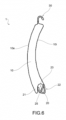
Figures 7 and 8 show two orthogonal views of the slat ofFigure 4 , respectively seen from the inner face and from the outer face; -
Figure 9 shows a lateral orthogonal view of a shutter according to a preferred embodiment of the invention, assembled with the slats shown inFigure 4 ; -
Figures 10 and 11 show two orthogonal views of the shutter ofFigure 9 , respectively seen from the inner side thereof and from the outer side thereof; -
Figures 12 and 13 show two perspective views of the shutter inFigure 9 , respectively seen from the inner and outer sides thereof; -
Figures 14 to 17 show the main operational steps for the manufacture of a slat and a shutter according to the invention; and -
Figure 18 shows a lateral orthogonal view of a section of a shutter production plant according to the invention, comprised between a second cutting unit and a first crushing unit; -
Figure 19 shows a top-down orthogonal view of the section of the plant shown inFigure 18 ; and -
Figure 20 shows a front orthogonal view of an assembly station of a shutter production plant according to the invention. - The
slat 1 for roller shutters according to the invention has been indicated as a whole by thereference number 1 in the accompanying figures. - Herein and in the following description and claims, reference will be made to the
slat 1 in an assembled condition inside a shutter. Therefore, any references to a lower or upper position or to a horizontal or vertical orientation should be interpreted in this sense. - According to a general embodiment of the invention, the
roller shutter slat 1 comprises an internally hollowelongated body 10, which extends along a longitudinal direction X and comprises afirst face 10e and asecond face 10i, opposite the first, which in use are designed to be turned respectively towards the outside and inside of the compartment closed by the shutter of which saidslat 1 is designed to form a part. - The
elongated body 10 comprises: - a
coupling cavity 20, which is formed along a firstlongitudinal edge 11 of saidelongated body 10 - a
coupling appendage 30 which extends from a secondlongitudinal edge 12 of saidelongated body 10, opposite thefirst edge 11. - Preferably, the
elongated body 10 consists of a box-shaped body made by bending and profiling a metal sheet. Thecoupling cavity 20 is obtained integrally within the box-shaped body by bending the metal sheet; thecoupling appendage 30 may also be obtained integrally within the box-shaped body (as shown in the attached figures) or alternatively it may constitute a separate piece applied to the box-shaped body. - As shown in
Figure 9 , thecoupling cavity 20 is designed to be engaged by thecoupling appendage 30 of a first slat, identical to saidslat 1, while thecoupling appendage 30 is designed to engage thecoupling cavity 20 of a second slat that is identical to saidslat 1. - In more detail, as shown in particular in
Figure 6 , thecoupling cavity 20 is delimited by afirst appendage 21 of theelongated body 10 obtained on thefirst face 10e and by asecond appendage 22 of theelongated body 10 obtained on thesecond face 10i. These twoappendages portion 23 that defines the bottom of saidcoupling cavity 20. - As shown in particular in
Figures 7 and 8 , thecoupling appendage 30 has a longitudinal extension L1 that is smaller than the longitudinal extension L2 of theelongated body 10 so as to define tworecesses longitudinal edge 12 of theelongated body 10. - According to a first aspect of the invention, as shown in particular in
Figures 4 and7 , theslat 1 comprises two notches (24', 24" which are obtained on said second appendage (22) near the two oppositelongitudinal ends 10' and 10" of saidelongated body 10 and extend transversely to said firstlongitudinal edge 11. - These two
notches second appendage 22, afirst tab 25 and asecond tab 26 which are placed at the two oppositelongitudinal ends 10' and 10" of saidelongated body 10. - Each
tab recesses - In use (as shown in the attached figures, and in particular in
Figures 4 ,6 ,7 ,9 and12 ), eachtab first appendage 21 so as to close thecoupling cavity 20 at the two opposite longitudinal ends 10' and 10" of theelongated body 10 once thecoupling appendage 30 of an adjacent slat has been inserted into the coupling cavity (20) with therespective recesses tabs - According to a further aspect of the invention, the
first appendage 21 develops continuously from one end of theelongated body 10 to the other, without interruption. - It was possible to verify in the field that closing the coupling cavity by bending only two end portions of the second appendage 22 (
tabs 25 and 26) provides more stable and secure locking of thecoupling appendage 30 of an adjacent slat within thecoupling cavity 20. - Furthermore, such a technical closure solution leaves the
first face 10e of theelongated body 10, i.e., the face of theslat 1 having a higher aesthetic value, unchanged. This significantly improves the aesthetic appearance of a shutter manufactured by assembling slats according to the invention. - The slat for roller shutters according to the present invention may therefore be assembled to form a shutter while ensuring a more stable and secure coupling between the coupling appendage and the hollow seat, without at the same time requiring changes to the external face of the slat itself.
- Preferably, as shown particularly in
Figure 6 , the aforementioned twonotches portion 23 which connects the twoappendages coupling cavity 20. In this way, bothtabs portion 23 and may be bent from the base starting from said connecting portion, maximizing the dimensions thereof within the coupling cavity when bent against thefirst appendage 21. This benefits the closure capacity of the coupling cavity on the part of the tabs. - Preferably, the
second appendage 22 is L-shaped. In this way both of thetabs tabs first appendage 21. This benefits the closure capacity of the coupling cavity on the part of the tabs. - Advantageously, as shown in the accompanying figures, the aforementioned two
recesses slat 1. - Advantageously, as shown in the accompanying figures, the two
tabs slat 1. - The subject of the present invention is also a
roller shutter 50 comprising a plurality of slats coupled with one another in pairs. Each of said slats is aslat 1 according to the invention, and in particular as described above. - In the
shutter 50, the twotabs slat 1 are bent against thefirst appendage 21 so as to close thecoupling cavity 20 at the two opposite longitudinal ends 10' and 10" of theelongated body 10 and thus retain thecoupling appendage 30 of the adjacent slat inside saidcoupling cavity 20. - As shown in particular in
Figures 11 and13 , theshutter 50 manufactured by assemblingslats 1 according to the invention does not show any machining marks on the external side associated with the assembly of the slats. This benefits the aesthetic appearance of the shutter. - Preferably, both
tabs slat 1 extend to the connectingportion 23 connecting thefirst appendage 21 to thesecond appendage 22. Bothtabs portion 23. - Preferably, both
tabs - The production process of the
slat 1 according to the invention and therelative shutter 50 will now be described. - As shown in
Figure 14 , the process starts from an elongated body preferably consisting of a box-shaped body obtained by bending and profiling a metal sheet. This elongated body corresponds to theelongated body 10 of the slat one according to the invention. By means of cutting operations transverse to the longitudinal direction X of the elongated body, sections corresponding to aslat 1 will be obtained. - Before cutting the elongated body, at the two
longitudinal edges notches notches longitudinal edge 11 and involves only thesecond appendage 22 implemented on thesecond face 10i (inner face) of the elongated body. A second pair ofnotches 24'", 24iv is made at the secondlongitudinal edge 12 and involves only thecoupling appendage 30 of the elongated body. The two pairs of notches are aligned transversely to one another in relation to the longitudinal direction X and straddle the cutting line T (or separation line) between twoslats 1' and 1" obtainable by cutting the elongated body. - The portion of the
second appendage 22 arranged between the first pair ofnotches tabs contiguous slats 1' and 1" along the longitudinal development of said elongated body. These twotabs slats 1' and 1" from one another. - Subsequently, as shown in
Figure 15 , the portion of thecoupling appendage 30 arranged between the second pair ofnotches 24‴, 24iv is removed by cutting in order to create one of said tworecesses contiguous slats 1' and 1" along the longitudinal development of said elongated body. These tworecesses slats 1' and 1" from one another. - Subsequently, as shown in
Figure 16 , the twocontiguous slats 1' and 1" are separated by cutting the elongated body along the cutting line T. After cutting, thetab 25 of one of the two slats 1' is bent against the relativefirst appendage 21. In this way, thecoupling cavity 20 of this slat 1' will then be closed at one longitudinal end before the coupling appendage of another slat is inserted into the aforementioned coupling cavity. Saidbent tab 25 will act as an abutment element for the insertion of thecoupling appendage 30 of said second slat. - The last slat obtained in succession by cutting the elongated body is ready to be coupled to the slat that was previously obtained by cutting the elongated body, as shown in
Figure 17 . Once the coupling appendage of the penultimate slat has been inserted into the coupling cavity of the last slat produced, thetab 26 of the last slat produced is also bent by pressing, thus completing the locking of the coupling appendage just inserted. - The operations described above are repeated in sequence until a
shutter 50 of a predefined length is completed. - The subject of the present invention is also a
plant 100 for the production of ashutter 50 according to the invention, by assemblingslats 1 according to the invention itself. - As shown in
Figures 18, 19 and20 , saidplant 100 comprises, in sequence in the direction of advancement V indicated inFigure 18 , the following: - a feeding unit for a continuous profile (not shown in the attached figures);
- a bending and profiling station for said continuous profile (not shown in the attached figures) for obtaining an elongated body corresponding to the
elongated body 10 of theslat 1 according to the present invention; - a
first cutting unit 110 movable at the advancement speed of the continuous profile, programmed to cut theelongated body 10 intoslats 1 of a predefined length; - an
assembly station 120 of saidslats 1 for forming a sheet of saidshutter 50. - The
assembly station 120 is arranged downstream of saidfirst cutting unit 110. - According to the invention, the
plant 100 further comprises asecond cutting unit 130 movable at the advancement speed of the continuous profile, which unit operates between said bending and profiling station and saidfirst cutting unit 110 and is programmed to implement the following: - a first pair of
transverse notches longitudinal edge 11 of theelongated body 10 at saidsecond appendage 22 and - a second pair of
transverse notches 24'", 24iv on the secondlongitudinal edge 12 of theelongated body 10 at saidcoupling appendage 30. - These two pairs of notches straddle the cutting line T between two slats.
- According to the invention, the
plant 100 further comprises ashearing unit 140 movable at the advancement speed of the continuous profile, which unit operates between saidsecond cutting unit 130 and saidfirst cutting unit 110 and is programmed to remove the portion of the continuous profile arranged between the second pair ofnotches 24‴, 24iv in order to make one of said tworecesses - According to the invention, the
plant 100 further comprises: - a first crushing
unit 150, which operates between saidfirst cutting unit 110 and saidassembly station 120 and is programmed to bend, against thefirst appendage 21 of saidelongated body 10, the profile portion that is comprised between one notch of said first pair ofnotches first tab slat 1 so as to close thecoupling cavity 20 at a first longitudinal end of saidslat 1; and - a second crushing
unit 160, which is integrated into saidassembly station 120 and is programmed to bend, against thefirst appendage 21 of said slat (1), the profile portion that is comprised between one notch of said first pair ofnotches second tab slat 1 so as to close thecoupling cavity 20, also at a second longitudinal end of saidslat 1 after the insertion of thecoupling appendage 30 of anotherslat 1 into thecoupling cavity 20. - The invention allows numerous advantages to be obtained, which have already been described in part.
- The
slat 1 for roller shutters according to the present invention may be assembled to form a shutter while ensuring a more stable and secure coupling between the coupling appendage and the hollow seat without at the same time requiring changes to the external face of the slat itself. This benefits the aesthetic aspect of the shutter obtainable by means of the assembly of slats according to the invention. - The
slat 1 for roller shutters according to the invention is furthermore simple and cost-effective to produce. - The invention thus conceived therefore achieves its intended objectives.
- Obviously, in practice it may also assume different forms and configurations from the one illustrated above, without thereby departing from the present scope of protection.
- Furthermore, all details may be replaced with technically equivalent elements, and the dimensions, shapes, and materials used may be any according to the needs.
Claims (10)
- Slat (1) for roller shutters, comprising an internally hollow elongated body (10) which extends along a longitudinal direction (X) and comprises a first face (10e) and a second face (10i) opposite the first, which in use are designed to be turned respectively outwards and inwards of the compartment closed by the shutter of which said slat is designed to be part, said elongated body (10) comprising:- a coupling cavity (20) which is obtained along a first longitudinal edge (11) of said elongated body (10) and is delimited by a first appendage (21) of the elongated body (10) obtained on the first face (10e) and by a second appendage (22) of the elongated body (10) obtained on the second face (10i), said two appendages (21, 22) being connected to each other by a connecting portion (23) defining the bottom of said coupling cavity, and- a coupling appendage (30), extending from a second longitudinal edge (12) of said elongated body (10), opposite the first edge (11),wherein said coupling cavity (20) is designed to be engaged by the coupling appendage (30) of a first slat identical to said slat (1), while said coupling appendage (30) is designed to engage the coupling cavity (20) of a second slat identical to said slat (1),
wherein said coupling appendage (30) has a smaller longitudinal extension (L1) than the longitudinal extension (L2) of said elongated body (10) so as to define two recesses (15, 16) at the ends of the second longitudinal edge (12) of said elongated body (10), characterized in that it comprises two notches (24', 24") which are obtained on said second appendage (22) near the two opposite longitudinal ends of said elongated body (10) and extend transversely to said first longitudinal edge (11), said two notches (24', 24") defining on said second appendage (22) a first tab (25) and a second tab (26) which are respectively placed at the two opposite longitudinal ends of said elongated body (10), each tab (25, 26) being in a position transversely opposite to one of said two recesses (15, 16) and having a longitudinal extension equal to or less than the respective recess, in use each tab (25, 26) being designed to be bent against said first appendage (21) so as to close the coupling cavity (20) at the two opposite longitudinal ends of the elongated body (10), once the coupling appendage (30) of an adjacent slat has been inserted into the coupling cavity (20) with the respective recesses (15, 16) at the tabs (25, 26) and in that said first appendage (21) extends continuously from one end to the other of the elongated body (10). - Slat according to claim 1, wherein said two notches (24', 24") extend transversely up to said connecting portion (23) so that both of said tabs (25, 26) extend up to said connecting portion (23).
- Slat according to claim 1 or 2, wherein said second appendage (22) is L-shaped and wherein both of said tabs (25, 26) are L-shaped.
- Slat according to any one of the preceding claims, wherein said two recesses (15, 16) have the same longitudinal extension.
- Slat according to any one of the preceding claims, wherein said two tabs (25, 26) have the same longitudinal extension.
- Slat according to any one of the preceding claims, wherein said elongated body (10) consists of a box-shaped body made by bending and profiling a metal sheet.
- Roller shutter (50), comprising a plurality of slats coupled together in pairs, characterized in that each of said slats is a slat (1) according to any one of the preceding claims and in that the two tabs (25, 26) of each slat (1) are bent against the first appendage (21) so as to close the coupling cavity (20) at the two opposite longitudinal ends of the elongated body (10) and thus retain the coupling appendage (30) of the adjacent slat inside said coupling cavity (20).
- Roller shutter (50) according to claim 7, wherein both of said tabs (25, 26) extend up to the connecting portion (23) connecting the first appendage (21) to the second appendage (22) and wherein both of said tabs (25, 26) are bent near the connecting portion (23).
- Roller shutter (50) according to claim 7 or 8, wherein both of said tabs (25, 26) are L-shaped and are bent at the portion defining the vertical section of the L shape.
- Plant (100) for producing a shutter according to any one of claims 7 to 9, comprising- a feeding unit of a continuous profile;- a bending and profiling station of said continuous profile to obtain an elongated body corresponding to the elongated body (10) of the slat according to any one of claims 1 to 6;- a first cutting unit (110) movable at the advancement speed of the continuous profile, programmed to cut said elongated body (10) into slats (1) of predefined length;- an assembly station (120) of said slats (1) to form a sheet of said shutter, arranged downstream of said first cutting unit (110),characterized in that it comprises:- a second cutting unit (130) movable at the advancement speed of the continuous profile, which is operating between said bending and profiling station and said first cutting unit (110) and is programmed to make a first pair of transverse notches on the first longitudinal edge (11) of the elongated body (10) at said second appendage (22) and a second pair of transverse notches on the second longitudinal edge (12) of the elongated body (10) at said coupling appendage (30), said two pairs of notches being made astride the cutting line between two slats; and- a shearing unit (140) movable at the advancement speed of the continuous profile, which is operating between said second cutting unit (130) and said first cutting unit (110) and is programmed to remove the portion of the continuous profile arranged between the second pair of notches in order to make one of said two recesses (15, 16) on two contiguous slats along the longitudinal extension of said elongated body;- a first crushing unit (150), which is operating between said first cutting unit (110) and said assembly station (120) and is programmed to bend against the first appendage (21) of said elongated body (10) the profile portion which is comprised between a notch of said first pair of notches and the cutting line (T) between two slats and which defines a first tab (25, 26) of said slat (1) so as to close the coupling cavity (20) at a first longitudinal end of said slat (1); and- a second crushing unit (160), which is integrated in said assembly station (120) and is programmed to bend against the first appendage (21) of said slat (1) the profile portion which is comprised between a notch of said first pair of notches and the cutting line (T) between two slats and which defines a second tab (25, 26) of said slat (1) so as to close the coupling cavity (20) also at a second longitudinal end of said slat (1) after the insertion of the coupling appendage (30) of another slat (1) into the coupling cavity (20).
Applications Claiming Priority (1)
| Application Number | Priority Date | Filing Date | Title |
|---|---|---|---|
| IT102021000029336A IT202100029336A1 (en) | 2021-11-19 | 2021-11-19 | SLAT FOR ROLLER SHUTTERS, SHUTTER INCLUDING THIS SLAT AND SYSTEM FOR CREATING SUCH SHUTTER |
Publications (2)
| Publication Number | Publication Date |
|---|---|
| EP4183966A1 true EP4183966A1 (en) | 2023-05-24 |
| EP4183966B1 EP4183966B1 (en) | 2026-02-11 |
Family
ID=80121739
Family Applications (1)
| Application Number | Title | Priority Date | Filing Date |
|---|---|---|---|
| EP22207672.1A Active EP4183966B1 (en) | 2021-11-19 | 2022-11-16 | Slat for roller shutters, shutter comprising such a slat and plant for manufacturing such a shutter |
Country Status (4)
| Country | Link |
|---|---|
| US (1) | US20230160257A1 (en) |
| EP (1) | EP4183966B1 (en) |
| ES (1) | ES3064749T3 (en) |
| IT (1) | IT202100029336A1 (en) |
Cited By (1)
| Publication number | Priority date | Publication date | Assignee | Title |
|---|---|---|---|---|
| EP4579055A1 (en) | 2023-12-29 | 2025-07-02 | Dallan S.p.A. | Plant for making roller shutter sheets |
Citations (4)
| Publication number | Priority date | Publication date | Assignee | Title |
|---|---|---|---|---|
| FR1558556A (en) * | 1967-03-18 | 1969-02-28 | ||
| FR2692313A1 (en) * | 1992-06-15 | 1993-12-17 | Acra Sarl | Roller shutter with lateral locking of slats - is assembled from slats by sliding hooked edge in following slat lip and locking assembly with wire in edge notch |
| US5343924A (en) * | 1992-07-31 | 1994-09-06 | Hoffman Robert E | System for maintaining alignment of roll-up blind slats |
| ITRA20090017A1 (en) * | 2009-05-26 | 2010-11-27 | C M P Costr Metallur Pappalardo Dei F Lli Pa | ANTI-BREAKAGE INSTRUMENTS FOR SHUTTERS. |
-
2021
- 2021-11-19 IT IT102021000029336A patent/IT202100029336A1/en unknown
-
2022
- 2022-11-16 ES ES22207672T patent/ES3064749T3/en active Active
- 2022-11-16 EP EP22207672.1A patent/EP4183966B1/en active Active
- 2022-11-18 US US18/057,143 patent/US20230160257A1/en not_active Abandoned
Patent Citations (4)
| Publication number | Priority date | Publication date | Assignee | Title |
|---|---|---|---|---|
| FR1558556A (en) * | 1967-03-18 | 1969-02-28 | ||
| FR2692313A1 (en) * | 1992-06-15 | 1993-12-17 | Acra Sarl | Roller shutter with lateral locking of slats - is assembled from slats by sliding hooked edge in following slat lip and locking assembly with wire in edge notch |
| US5343924A (en) * | 1992-07-31 | 1994-09-06 | Hoffman Robert E | System for maintaining alignment of roll-up blind slats |
| ITRA20090017A1 (en) * | 2009-05-26 | 2010-11-27 | C M P Costr Metallur Pappalardo Dei F Lli Pa | ANTI-BREAKAGE INSTRUMENTS FOR SHUTTERS. |
Cited By (1)
| Publication number | Priority date | Publication date | Assignee | Title |
|---|---|---|---|---|
| EP4579055A1 (en) | 2023-12-29 | 2025-07-02 | Dallan S.p.A. | Plant for making roller shutter sheets |
Also Published As
| Publication number | Publication date |
|---|---|
| ES3064749T3 (en) | 2026-04-28 |
| EP4183966B1 (en) | 2026-02-11 |
| US20230160257A1 (en) | 2023-05-25 |
| IT202100029336A1 (en) | 2023-05-19 |
Similar Documents
| Publication | Publication Date | Title |
|---|---|---|
| CA2579978C (en) | Muntin bar clip and muntin bar assembly | |
| EP4183966B1 (en) | Slat for roller shutters, shutter comprising such a slat and plant for manufacturing such a shutter | |
| US6482500B1 (en) | Prefabricated plastic shed and components therefor | |
| EP3094804A1 (en) | Interlocking rolling sheet door system | |
| CA2500148C (en) | Flush mounted louver end cap with tolerance flashing | |
| KR20170055654A (en) | the zigzag assembly type structure of window frames as well as window and doors | |
| EP1231352A2 (en) | Method and apparatus for making notched muntin bars having two finishes | |
| EP0466786A1 (en) | Window to be inserted in an opening in a wall of sandwich-type. | |
| EP3844364B1 (en) | Bottom profile of a frame of a window or door and method for the manufacture of such a bottom profile | |
| US20060248801A1 (en) | Pivoting arch frame | |
| EP4579055A1 (en) | Plant for making roller shutter sheets | |
| US20100300630A1 (en) | Cellular Shade | |
| EP2128371A1 (en) | Method for insulating a jamb for exterior joinery work | |
| IT202100005423U1 (en) | SLAT FOR ROLLER SHUTTERS, SHUTTER INCLUDING THIS SLAT AND SYSTEM FOR CREATING SUCH SHUTTER | |
| US8104238B2 (en) | Window spacer and corner-fastening concept | |
| EP2857627A1 (en) | Roller shutter slat and method of producing a roller shutter slat | |
| ITPD970060A1 (en) | PERFECTED ELASTIC HINGE FOR GLASSES | |
| US7717140B2 (en) | Narrow cranked heald | |
| US462238A (en) | Manufacture of hinges | |
| JP5463103B2 (en) | Shutter slats | |
| US2976607A (en) | Method of making telescopic bracelet inner box elements | |
| DE10325561A1 (en) | Position fixation of a grip tab with a panel formed from the panel (anti rotation bead) | |
| CN100590290C (en) | Rolling gate and its profiles | |
| US1848673A (en) | Door or window construction | |
| CN202850749U (en) | Entrance door frame |
Legal Events
| Date | Code | Title | Description |
|---|---|---|---|
| PUAI | Public reference made under article 153(3) epc to a published international application that has entered the european phase |
Free format text: ORIGINAL CODE: 0009012 |
|
| STAA | Information on the status of an ep patent application or granted ep patent |
Free format text: STATUS: THE APPLICATION HAS BEEN PUBLISHED |
|
| AK | Designated contracting states |
Kind code of ref document: A1 Designated state(s): AL AT BE BG CH CY CZ DE DK EE ES FI FR GB GR HR HU IE IS IT LI LT LU LV MC ME MK MT NL NO PL PT RO RS SE SI SK SM TR |
|
| P01 | Opt-out of the competence of the unified patent court (upc) registered |
Effective date: 20230526 |
|
| STAA | Information on the status of an ep patent application or granted ep patent |
Free format text: STATUS: REQUEST FOR EXAMINATION WAS MADE |
|
| 17P | Request for examination filed |
Effective date: 20231122 |
|
| RBV | Designated contracting states (corrected) |
Designated state(s): AL AT BE BG CH CY CZ DE DK EE ES FI FR GB GR HR HU IE IS IT LI LT LU LV MC ME MK MT NL NO PL PT RO RS SE SI SK SM TR |
|
| RIN1 | Information on inventor provided before grant (corrected) |
Inventor name: DALLAN, ANDREA |
|
| RIC1 | Information provided on ipc code assigned before grant |
Ipc: E06B 9/15 20060101AFI20250703BHEP |
|
| GRAP | Despatch of communication of intention to grant a patent |
Free format text: ORIGINAL CODE: EPIDOSNIGR1 |
|
| STAA | Information on the status of an ep patent application or granted ep patent |
Free format text: STATUS: GRANT OF PATENT IS INTENDED |
|
| INTG | Intention to grant announced |
Effective date: 20251009 |
|
| GRAS | Grant fee paid |
Free format text: ORIGINAL CODE: EPIDOSNIGR3 |
|
| GRAA | (expected) grant |
Free format text: ORIGINAL CODE: 0009210 |
|
| STAA | Information on the status of an ep patent application or granted ep patent |
Free format text: STATUS: THE PATENT HAS BEEN GRANTED |
|
| AK | Designated contracting states |
Kind code of ref document: B1 Designated state(s): AL AT BE BG CH CY CZ DE DK EE ES FI FR GB GR HR HU IE IS IT LI LT LU LV MC ME MK MT NL NO PL PT RO RS SE SI SK SM TR |
|
| REG | Reference to a national code |
Ref country code: CH Ref legal event code: F10 Free format text: ST27 STATUS EVENT CODE: U-0-0-F10-F00 (AS PROVIDED BY THE NATIONAL OFFICE) Effective date: 20260211 Ref country code: GB Ref legal event code: FG4D |
|
| REG | Reference to a national code |
Ref country code: DE Ref legal event code: R096 Ref document number: 602022030104 Country of ref document: DE |
|
| REG | Reference to a national code |
Ref country code: IE Ref legal event code: FG4D |
|
| REG | Reference to a national code |
Ref country code: ES Ref legal event code: FG2A Ref document number: 3064749 Country of ref document: ES Kind code of ref document: T3 Effective date: 20260428 |
|
| REG | Reference to a national code |
Ref country code: NL Ref legal event code: MP Effective date: 20260211 |
|
| PG25 | Lapsed in a contracting state [announced via postgrant information from national office to epo] |
Ref country code: RS Free format text: LAPSE BECAUSE OF FAILURE TO SUBMIT A TRANSLATION OF THE DESCRIPTION OR TO PAY THE FEE WITHIN THE PRESCRIBED TIME-LIMIT Effective date: 20260511 |
|
| PG25 | Lapsed in a contracting state [announced via postgrant information from national office to epo] |
Ref country code: PL Free format text: LAPSE BECAUSE OF FAILURE TO SUBMIT A TRANSLATION OF THE DESCRIPTION OR TO PAY THE FEE WITHIN THE PRESCRIBED TIME-LIMIT Effective date: 20260211 |
|
| PG25 | Lapsed in a contracting state [announced via postgrant information from national office to epo] |
Ref country code: GR Free format text: LAPSE BECAUSE OF FAILURE TO SUBMIT A TRANSLATION OF THE DESCRIPTION OR TO PAY THE FEE WITHIN THE PRESCRIBED TIME-LIMIT Effective date: 20260512 |
|
| REG | Reference to a national code |
Ref country code: LT Ref legal event code: MG9D |
|
| PG25 | Lapsed in a contracting state [announced via postgrant information from national office to epo] |
Ref country code: LT Free format text: LAPSE BECAUSE OF FAILURE TO SUBMIT A TRANSLATION OF THE DESCRIPTION OR TO PAY THE FEE WITHIN THE PRESCRIBED TIME-LIMIT Effective date: 20260211 |
|
| PG25 | Lapsed in a contracting state [announced via postgrant information from national office to epo] |
Ref country code: NO Free format text: LAPSE BECAUSE OF FAILURE TO SUBMIT A TRANSLATION OF THE DESCRIPTION OR TO PAY THE FEE WITHIN THE PRESCRIBED TIME-LIMIT Effective date: 20260511 |
|
| PG25 | Lapsed in a contracting state [announced via postgrant information from national office to epo] |
Ref country code: FI Free format text: LAPSE BECAUSE OF FAILURE TO SUBMIT A TRANSLATION OF THE DESCRIPTION OR TO PAY THE FEE WITHIN THE PRESCRIBED TIME-LIMIT Effective date: 20260211 Ref country code: SE Free format text: LAPSE BECAUSE OF FAILURE TO SUBMIT A TRANSLATION OF THE DESCRIPTION OR TO PAY THE FEE WITHIN THE PRESCRIBED TIME-LIMIT Effective date: 20260211 Ref country code: AT Free format text: LAPSE BECAUSE OF FAILURE TO SUBMIT A TRANSLATION OF THE DESCRIPTION OR TO PAY THE FEE WITHIN THE PRESCRIBED TIME-LIMIT Effective date: 20260211 |
|
| REG | Reference to a national code |
Ref country code: AT Ref legal event code: MK05 Ref document number: 1885768 Country of ref document: AT Kind code of ref document: T Effective date: 20260211 |
|
| PG25 | Lapsed in a contracting state [announced via postgrant information from national office to epo] |
Ref country code: HR Free format text: LAPSE BECAUSE OF FAILURE TO SUBMIT A TRANSLATION OF THE DESCRIPTION OR TO PAY THE FEE WITHIN THE PRESCRIBED TIME-LIMIT Effective date: 20260211 |
|
| PG25 | Lapsed in a contracting state [announced via postgrant information from national office to epo] |
Ref country code: PT Free format text: LAPSE BECAUSE OF FAILURE TO SUBMIT A TRANSLATION OF THE DESCRIPTION OR TO PAY THE FEE WITHIN THE PRESCRIBED TIME-LIMIT Effective date: 20260611 Ref country code: IS Free format text: LAPSE BECAUSE OF FAILURE TO SUBMIT A TRANSLATION OF THE DESCRIPTION OR TO PAY THE FEE WITHIN THE PRESCRIBED TIME-LIMIT Effective date: 20260611 |
|
| PG25 | Lapsed in a contracting state [announced via postgrant information from national office to epo] |
Ref country code: NL Free format text: LAPSE BECAUSE OF FAILURE TO SUBMIT A TRANSLATION OF THE DESCRIPTION OR TO PAY THE FEE WITHIN THE PRESCRIBED TIME-LIMIT Effective date: 20260211 |
|
| PG25 | Lapsed in a contracting state [announced via postgrant information from national office to epo] |
Ref country code: LV Free format text: LAPSE BECAUSE OF FAILURE TO SUBMIT A TRANSLATION OF THE DESCRIPTION OR TO PAY THE FEE WITHIN THE PRESCRIBED TIME-LIMIT Effective date: 20260211 |
|
| PG25 | Lapsed in a contracting state [announced via postgrant information from national office to epo] |
Ref country code: BG Free format text: LAPSE BECAUSE OF FAILURE TO SUBMIT A TRANSLATION OF THE DESCRIPTION OR TO PAY THE FEE WITHIN THE PRESCRIBED TIME-LIMIT Effective date: 20260211 |