EP4183958B1 - Doorlock with lock status determination - Google Patents
Doorlock with lock status determination Download PDFInfo
- Publication number
- EP4183958B1 EP4183958B1 EP21306598.0A EP21306598A EP4183958B1 EP 4183958 B1 EP4183958 B1 EP 4183958B1 EP 21306598 A EP21306598 A EP 21306598A EP 4183958 B1 EP4183958 B1 EP 4183958B1
- Authority
- EP
- European Patent Office
- Prior art keywords
- handle
- doorlock
- axis
- rotation
- ring
- Prior art date
- Legal status (The legal status is an assumption and is not a legal conclusion. Google has not performed a legal analysis and makes no representation as to the accuracy of the status listed.)
- Active
Links
Images




Classifications
-
- E—FIXED CONSTRUCTIONS
- E05—LOCKS; KEYS; WINDOW OR DOOR FITTINGS; SAFES
- E05B—LOCKS; ACCESSORIES THEREFOR; HANDCUFFS
- E05B41/00—Locks with visible indication as to whether the lock is locked or unlocked
-
- E—FIXED CONSTRUCTIONS
- E05—LOCKS; KEYS; WINDOW OR DOOR FITTINGS; SAFES
- E05B—LOCKS; ACCESSORIES THEREFOR; HANDCUFFS
- E05B47/00—Operating or controlling locks or other fastening devices by electric or magnetic means
- E05B47/06—Controlling mechanically-operated bolts by electro-magnetically-operated detents
- E05B47/0611—Cylinder locks with electromagnetic control
- E05B47/0615—Cylinder locks with electromagnetic control operated by handles, e.g. by knobs
-
- E—FIXED CONSTRUCTIONS
- E05—LOCKS; KEYS; WINDOW OR DOOR FITTINGS; SAFES
- E05B—LOCKS; ACCESSORIES THEREFOR; HANDCUFFS
- E05B47/00—Operating or controlling locks or other fastening devices by electric or magnetic means
- E05B2047/0048—Circuits, feeding, monitoring
- E05B2047/0067—Monitoring
Definitions
- the invention relates to the field of smart doorlock and concerns a doorlock configured to switch between a locked state and an unlocked state.
- the invention also concerns a method for determining a locked state and an unlocked state of a doorlock.
- Electromechanical lock and key with identification code are widespread. They enable authorized key holders to have access to locked rooms if the identification code of the key, or the shape of the key, corresponds to a predetermined code, or a predetermined shape, in relation with the electromechanical lock.
- the key may be an ordinary looking key to insert into the lock or an access badge to pass in front of the lock.
- the electromechanical lock comprises a processor configured to compare the identification code of the key with the predetermined code. If the identification code corresponds to the predetermined code, the electromechanical lock switches from its locked state to its unlocked state.
- Commonly locks are formed with a body that can be easily unscrewed by a locksmith to facilitate rekeying.
- the body has the function to lock and unlock the lock.
- a lock body may be found under the form of a European cylinder (defined by the DIN18251).
- a European cylinder is a type of lock cylinder.
- a body may not be in the form of a cylinder.
- a lock body may be inserted into a lock or a mortise lock or a slot-in lock. This function offers the advantage of allowing its change without altering the boltwork hardware. Removing the body typically requires only loosening a set screw, then sliding the body from the boltwork.
- a lock mechanism, or doolock, 5 has a deadbolt 6 that may be entirely positioned inside the housing of the door 7 in the unlocked state.
- this deadbolt6 projects beyond the door 7 and is inserted into a slot of the door frame (not represented), thus locking the door to the frame.
- the movement of the deadbolt 6 can be mechanically obtained, for example by a rotation of a key inserted into the doorlock or by rotation of a handle 8, preferably an indoor handle.
- the rotation of the key clockwise, respectively anticlockwise, causes a pin to rotate accordingly, thereby making the deadbolt 6 translate either outside the door to be inserted into the slot of the door frame, or inside the door.
- the door may comprise a handle 9 to activate the latch 2 of the door. This handle 9 (together with the latch 2) enables to open and close the door in its unlocked state, to enter or leave the room.
- the rotation of the indoor handle enables to make the deadbolt translate between various positions, from a position totally inserted in the door to a position where the deadbolt extends beyond the door, so as to be inserted into the corresponding slot of the door frame, and vice versa depending on the direction of the rotation of the indoor handle (clockwise and/or anticlockwise).
- WO2005066440A1 provides a mechanism for monitoring the respective position of a window handle from a distance.
- a handle shaft and/or handle bearing bears a circuit slide which controls the sensors associated with the individual positions of the handle.
- the output signals of the sensors are transmitted by radio or via a line to a report centre.
- the interchangeable electromechanical lock core may include a moveable plug having a first position relative to a lock core body which corresponds to the lock device being in the locked state and a second position relative to a lock core body which corresponds to the lock device being in the unlocked state.
- a solution to overcome this drawback is to provide a doorlock enabling to retrieve the lock status of the doorlock by analyzing the rotation and the direction of the rotation of the handle.
- the subject of the invention is a doorlock configured to switch between a locked state and an unlocked state, the doorlock extending along a first axis between a first end and a second end, the doorlock comprising:
- the doorlock of the invention comprises at least two magnets, two adjacent magnets of the at least two magnets forming an angular portion from the first axis with a predefined angle.
- the processor is further configured to send to a remote control through a communication link the angular displacement of the handle and the direction of the rotation of the handle around the first axis.
- each of the at least two magnets comprises a north pole and a south pole superimposed on the north pole according to a second axis parallel to the first axis, respectively in a first direction and in a second direction, opposite to the first direction, for two adjacent magnets of the at least two magnets.
- the at least two magnets are distributed regularly on the ring.
- the processor comprises a memory configured to store a position of the handle.
- the processor is configured to read an identification code of an identification key and configured to cause the doorlock to switch from the locked state to the unlocked state if the identification code of the identification key is an authorized code of the doorlock.
- the invention also relates to a method for determining a locked state and an unlocked state of a doorlock, the doorlock extending along a first axis between a first end and a second end, the doorlock comprising:
- the method of the invention comprises a step of storing a position of the handle.
- the method of the invention further comprises a step of determining the locked state and the unlocked state of the doorlock from the stored position and the angular displacement of the handle and the direction of the rotation of the handle.
- a door is an opening unit enabling the access to a room (or from a room to the outside) through an aperture.
- the door is connected to a door frame that frames the aperture and is fixed to the walls around the aperture.
- the door In an unlocked state of the door, the door is mobile in relation to the door frame, typically mobile in rotation around doors hinges (or in translation in the case the door and the door frame are configured to let the door slide through a part of the door frame and into the wall).
- the door may be in an open configuration or a closed configuration. In the closed configuration, the door covers the aperture (i.e. no one can go through the aperture).
- the door is equipped with a lock mechanism.
- the lock mechanism has a latch that is either inserted into a slot of the door frame (the door is closed) or retracted inside the door (the door is no longer attached to the door frame and may be open). In the closed configuration, the latch is inserted into the slot of the door frame.
- a lock clutch is connected to the latch.
- the lock clutch is usually engaged with both the indoor and outdoor door knobs. This enables a user to activate the lock clutch to make the latch move by moving one of the door knobs or handles. Therefore a user has to move a door knob of the door to switch from the closed configuration of the door to the open configuration of the door. Indeed, the lock clutch being engaged with the knob, the movement of the knob leads to the movement of the latch. Moving the door knob makes the latch retract into the door. The user can pull or push the door to open it.
- the lock mechanism can be either in a locked state or an unlocked state.
- the unlocked state corresponds to the case discussed above.
- the door may be open by a user when activating a door knob and pushing or pulling the door.
- the lock mechanism has a deadbolt entirely positioned inside the locking mechanism in the unlocked state. In the locked state, this deadbolt projects beyond the lock mechanism and is inserted into a slot of the door frame, thus locking the door to the frame.
- a user has to rotate the key with the corresponding rotation of the key inside the lock mechanism, or rotate the indoor handle with the corresponding rotation (which means with the adapted angular displacement in the corresponding direction).
- a multi-point lock also known as a safety lock, provides extra security as it distributes the locking points (i.e. a plurality of deadbolts) over the entire door.
- the most common multi-point lock is the three-point lock composed of a main deadbolt in the center and two other bolts at the top and at the bottom actuated by a rod.
- Some multi-point locks may have up to ten locking points.
- Figure 1 schematically represents a lock mechanism of a door of the prior art and was discussed in the introduction.
- FIG. 2 schematically represents a doorlock 10 according to the invention.
- the doorlock 10 is configured to switch between a locked state and an unlocked state.
- the doorlock extends along a first axis X between a first end 11 and a second end 12.
- the doorlock comprises a handle 13 positioned at the first end 11 of the doorlock, the handle 13 being mobile in rotation around the first axis X.
- the doorlock comprises a pin 14 positioned between the first end 11 and the second end 12 of the doorlock, the pin 14 extending radially from the first axis X, the pin being mobile in rotation around the first axis X, and configured to be rotatably driven by a rotation of the handle 13 or by a rotation of an associated key inserted into the outdoor handle at the second end 12, thereby making the doorlock switch between the locked state and the unlocked state.
- the doorlock 10 may be configured to cooperate with at least one identification key 17.
- the doorlock 10 may comprise at its second end 12 a key hole 16 shaped to accept insertion of the identification key 17. A rotation of the identification key may lead to the rotation of the pin, thereby making the doorlock switch between the locked state and the unlocked state.
- the doorlock 10 may comprise a processor configured to read an identification code of the identification key 17 and configured to cause the doorlock 10 to switch from the locked state to the unlocked state if the identification code of the identification key 17 is an authorized code of the doorlock 10.
- the processor of the doorlock 10 may comprise an algorithm that is able to generate a plurality of codes.
- the identification key 17 When inserting the identification key 17 into the key hole or having the identification key 17 or a smartphone close to the doorlock 10, (i.e. until about 10 meters of the doorlock, for example thanks to the BLE technology (acronym of Bluetooth TM Low Energy technology)), one of the code generated by the algorithm of the processor is transmitted from the processor to the identification key 17 when this one is inserted into the key hole 16.
- the processor should receive from the identification key 17 an authorized code, that is to say an identification code corresponding to the code transmitted by the processor.
- the identification key 17 There is a communication between the doorlock 10 and the identification key 17. And if the processor receives from the identification key 17, as a response to its code, an authorized code, the identification key 17 is considered as an authorized key for switching between the locked state and the unlocked state.
- the communication between the identification key and the doorlock may use a direct electrical contact, an RF communication link (NFC TM , Bluetooth TM , Wi-Fi TM , Zigbee TM or other low power RF communication standard or proprietary means), an optical or an acoustical communication means.
- RF communication link NFC TM , Bluetooth TM , Wi-Fi TM , Zigbee TM or other low power RF communication standard or proprietary means
- FIG. 3 schematically represents a doorlock according to the invention.
- the doorlock 10 comprises a PCB 18 (Printed Circuit Board) secured in an immovable manner inside the handle 13.
- the doorlock 10 comprises a ring 19 centered around the first axis X, and fixed to the handle 13 so that the rotation of the handle 13 makes the ring 19 rotate.
- a clockwise rotation of a defined angle of the handle 13 around the first axis X makes the ring 19 rotate clockwise of the same defined angle around the first axis X.
- an anticlockwise rotation of another defined angle of the handle 13 around the first axis X makes the ring 19 rotate anticlockwise of the same another defined angle around the first axis X.
- the doorlock 10 comprises at least one magnet, but preferably at least two magnets 20 positioned on the ring 19.
- the doorlock 10 comprises two reed switches 23 positioned on the PCB 18, preferably facing the ring 19.
- a reed switch is an electrical switch operated by an applied magnetic field. The reed switch is closed when a magnet is closed of the reed switch and the reed switch is open when the magnet is too far. This principle is described in detail below.
- the PCB 18 comprises a processor configured to determine an angular displacement of the handle 13 and a direction of the rotation of the handle 13 around the first axis X, based on an electric field generated by the two reed switches 23 when the handle 13 is actuated in rotation around the first axis X.
- Figure 4 schematically represents the working principle of a reed switch included in a doorlock according to the invention.
- a reed switch is an electrical switch operated by an applied magnetic field. The reed switch is closed when a magnet is closed of the reed switch (on the left hand side of the figure) and the reed switch is open when the magnet is too far (on the right hand side of the figure).
- the operating mode of the reed switch described above is an example of a so-called "normally opened” reed switch (i.e. a reed switch that is normally in its open state and is closed when an magnetic field is applied in its vicinity).
- the invention similarly applies to a so-called “normally closed” reed switch (i.e. a reed switch that is normally in its closed state and is open when a magnetic field is applied in its vicinity).
- the ring rotates similarly and so do the magnets 20 that pass in front of the reed switches positioned on the PCB.
- the rotation of the handle leads to the approach and distancing of a magnet in regards of a reed switch. Each reed switch changes accordingly its state between open and close.
- FIG. 5 schematically represents the ring 19 of the doorlock according to the invention.
- each of the at least two magnets 20 comprises a north pole and a south pole superimposed on the north pole according to a second axis Y parallel to the first axis X, respectively in a first direction and in a second direction, opposite to the first direction, for two adjacent magnets 20 of the at least two magnets.
- This alternance of the north and south pole ensures that between two adjacent magnets the magnetic field is zero, which causes the reed switch to open.
- This technical feature ensures all reed switches are open when passing between two magnets. The reed switch is closed when it approaches a magnet. Nevertheless, this alternance of the poles is not compulsory.
- Figure 6 schematically represents the principle of the doorlock according to the invention.
- the magnets 20 are labelled from 1 to 6 and the reed switches 23 are labelled A and B and installed on the main PCB.
- the processor of the doorlock is configured to analyse the angular distance of the rotation (how many degrees compared to the previous position) and its direction (clockwise or anti-clockwise), as explained thereafter.
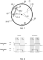
- Figure 7 schematically represents the principle of the doorlock according to the invention.
- This figure depicts a non-limitative example of the ring having 6 magnets.
- the invention applies similarly with less than 6 magnets, for example 2 or 3, or with more than 6 magnets, for example 10 or 12.
- the magnets are preferably distributed regularly on the ring.
- the doorlock 10 comprises at least two magnets 20 positioned on the ring 19.
- two adjacent magnets 20 of the at least two magnets form an angular portion 21 from the first axis X with an angle 22 predefined by the position of the magnets.
- the angle is 60°.
- the angle 22 would be 30°.
- the angle 22 may take other values depending on the position of the magnets 20 on the ring 19.
- the two reed switches 23 are placed on the PCB 18, forming an angular portion from the first axis X with an angle 24.
- the angle 24 is 45° in the depicted example, but it could have other values, for example 40° or 50°.
- the magnets and reed switches have a 15° precision since there are 4 reed switch events for a 60° rotation.
- the angle 22 may be less than the angle 24.
- the values of the angles 22, 24 depend on the position of the magnets 20 on the ring 19, the distance of the PCB from the ring and the distance between between the reed switches. These geometrical parameters may be adapted according to the desired accuracy of the detection.
- Figure 8 schematically represents the analysis of the direction of the rotation of the handle of the doorlock of the invention, based on the relative movement of the magnets passing in front of the two reed switches.
- the indoor handle 13 is turned clockwise in one of these cases:
- the indoor handle 13 is turned anti-clockwise in one of these cases:
- Figure 9 represents an example of the reed switch states for a clockwise rotation of the handle of the doorlock of the invention.
- the magnets are placed every 60 degrees on the ring of the doorlock, it means that during a 60° rotation, the two reed switches will measure four changes of state (4 events). This means that the indoor handle turns 15° for each event on reed switches (see figure 9 and figure 10 ).
- Figure 10 represents an example of the reed switch states for an anticlockwise rotation of the handle of the doorlock of the invention.
- analyzing the evolution of the signal indicates the direction of the rotation (clockwise and anticlockwise) and the angle of the rotation performed by the handle.
- the processor of the doorlock may comprise a memory configured to store a position of the handle. After analyzing the evolution of the signal and determining the direction and the angle of the rotation, and based on the previously stored position of the handle, it is possible to determine an updated position of the handle, that can also be stored in the memory.
- the processor may further be configured to send to a remote control through a communication link the angular displacement of the handle and the direction of the rotation of the handle around the first axis.
- the processor may also calculate, based on the previous stored position of the handle, its angular displacement and the direction of the rotation whether the doorlock is in its locked or unlocked state. This information can be further sent to a remote control, for example to a smartphone via a web application.
- Figure 11 represents a block diagram of the steps of a method for determining a locked state and an unlocked state of the doorlock 10 according to the invention. According to the invention, the method comprises following steps:
- the method may further comprise a step 130 of storing a position of the handle.
- the method may further comprise a step 140 of determining the locked state and the unlocked state of the doorlock from the stored position and the angular displacement of the handle and the direction of the rotation of the handle.
Landscapes
- Physics & Mathematics (AREA)
- Electromagnetism (AREA)
- Lock And Its Accessories (AREA)
Description
- The invention relates to the field of smart doorlock and concerns a doorlock configured to switch between a locked state and an unlocked state. The invention also concerns a method for determining a locked state and an unlocked state of a doorlock.
- Electromechanical lock and key with identification code, or key with a specific shape without identification code, are widespread. They enable authorized key holders to have access to locked rooms if the identification code of the key, or the shape of the key, corresponds to a predetermined code, or a predetermined shape, in relation with the electromechanical lock. The key may be an ordinary looking key to insert into the lock or an access badge to pass in front of the lock.
- In case of a key with an identification code, the electromechanical lock comprises a processor configured to compare the identification code of the key with the predetermined code. If the identification code corresponds to the predetermined code, the electromechanical lock switches from its locked state to its unlocked state.
- Commonly locks are formed with a body that can be easily unscrewed by a locksmith to facilitate rekeying. The body has the function to lock and unlock the lock. A lock body may be found under the form of a European cylinder (defined by the DIN18251). A European cylinder is a type of lock cylinder. There exist other profiles of lock bodies like the oval cylinder that is used in the Nordic countries. A body may not be in the form of a cylinder. A lock body may be inserted into a lock or a mortise lock or a slot-in lock. This function offers the advantage of allowing its change without altering the boltwork hardware. Removing the body typically requires only loosening a set screw, then sliding the body from the boltwork.
- As depicted in
figure 1 , a lock mechanism, or doolock, 5 has adeadbolt 6 that may be entirely positioned inside the housing of thedoor 7 in the unlocked state. In the locked state (state depicted infigure 1 ), this deadbolt6 projects beyond thedoor 7 and is inserted into a slot of the door frame (not represented), thus locking the door to the frame. The movement of thedeadbolt 6 can be mechanically obtained, for example by a rotation of a key inserted into the doorlock or by rotation of a handle 8, preferably an indoor handle. The rotation of the key clockwise, respectively anticlockwise, causes a pin to rotate accordingly, thereby making thedeadbolt 6 translate either outside the door to be inserted into the slot of the door frame, or inside the door. To switch from the locked state of the door to the unlocked state of the door, a user has to rotate the key with the corresponding rotation of the key inside the doorlock, or rotate the indoor handle 8 with the corresponding rotation (which means with the adapted angular displacement in thecorresponding direction 3, 4) to generate a rotation of the pin that actuates in translation thedeadbolt 6. The door may comprise ahandle 9 to activate thelatch 2 of the door. This handle 9 (together with the latch 2) enables to open and close the door in its unlocked state, to enter or leave the room. - Therefore, the rotation of the indoor handle enables to make the deadbolt translate between various positions, from a position totally inserted in the door to a position where the deadbolt extends beyond the door, so as to be inserted into the corresponding slot of the door frame, and vice versa depending on the direction of the rotation of the indoor handle (clockwise and/or anticlockwise).
- However, after having turned the handle clockwise and/or anticlockwise, it is difficult for a user to estimate the position of the deadbolt in the door or in the slot of the door frame. The existing doorlocks do not offer the possibility to determine if the doorlock is locked or unlocked.
-
WO2005066440A1 provides a mechanism for monitoring the respective position of a window handle from a distance. A handle shaft and/or handle bearing bears a circuit slide which controls the sensors associated with the individual positions of the handle. The output signals of the sensors are transmitted by radio or via a line to a report centre. -
US2019/218826 Presents an interchangeable electro-mechanical lock core for use with a lock device having a locked state and an unlocked state is disclosed. The interchangeable electromechanical lock core may include a moveable plug having a first position relative to a lock core body which corresponds to the lock device being in the locked state and a second position relative to a lock core body which corresponds to the lock device being in the unlocked state. - There is consequently a need for a doorlock configured to enable to retrieve the status of the doorlock to know whether the doorlock is in its locked state of in its unlocked state.
- A solution to overcome this drawback is to provide a doorlock enabling to retrieve the lock status of the doorlock by analyzing the rotation and the direction of the rotation of the handle.
- To this end, the subject of the invention is a doorlock configured to switch between a locked state and an unlocked state, the doorlock extending along a first axis between a first end and a second end, the doorlock comprising:
- a handle positioned at the first end of the doorlock, the handle being mobile in rotation around the first axis,
- a pin positioned between the first end and the second end of the doorlock, the pin extending radially from the first axis, the pin being mobile in rotation around the first axis, and configured to be rotatably driven by a rotation of the handle, thereby making the doorlock switch between the locked state and the unlocked state,
- a PCB secured in an immovable manner inside the handle,
- a ring centered around the first axis, and fixed to the handle so that the rotation of the handle makes the ring rotate,
- at least one magnet positioned on the ring,
- two reed switches positioned on the PCB, preferably facing the ring,
- Advantageously, the doorlock of the invention comprises at least two magnets, two adjacent magnets of the at least two magnets forming an angular portion from the first axis with a predefined angle.
- Advantageously, the processor is further configured to send to a remote control through a communication link the angular displacement of the handle and the direction of the rotation of the handle around the first axis.
- Advantageously each of the at least two magnets comprises a north pole and a south pole superimposed on the north pole according to a second axis parallel to the first axis, respectively in a first direction and in a second direction, opposite to the first direction, for two adjacent magnets of the at least two magnets.
- Advantageously the at least two magnets are distributed regularly on the ring.
- Advantageously the processor comprises a memory configured to store a position of the handle.
- Advantageously the processor is configured to read an identification code of an identification key and configured to cause the doorlock to switch from the locked state to the unlocked state if the identification code of the identification key is an authorized code of the doorlock.
- The invention also relates to a method for determining a locked state and an unlocked state of a doorlock, the doorlock extending along a first axis between a first end and a second end, the doorlock comprising:
- a handle positioned at the first end of the doorlock, the handle being mobile in rotation around the first axis,
- a pin positioned between the first end and the second end of the doorlock, the pin extending radially from the first axis, the pin being mobile in rotation around the first axis, and configured to be rotatably driven by a rotation of the handle, thereby making the doorlock switch between the locked state and the unlocked state,
- a PCB secured in an immovable manner inside the handle, the PCB comprising a processor,
- a ring centered around the first axis, and fixed to the handle so that the rotation of the handle makes the ring rotate,
- at least one magnet positioned on the ring,
- two reed switches positioned on the PCB, preferably facing the ring,
- rotation of the handle about the first axis according to an angular displacement of the handle and a direction of the rotation of the handle around the first axis,
- generation of a first electrical signal and a second electrical signal by the two reed switches,
- determination of the angular displacement of the handle and the direction of the rotation of the handle around the first axis by the processor based on the first electrical signal and the second electrical signal,
- determining a locked/unlocked state of the doorlock.
- Advantageously the method of the invention comprises a step of storing a position of the handle.
- Advantageously the method of the invention further comprises a step of determining the locked state and the unlocked state of the doorlock from the stored position and the angular displacement of the handle and the direction of the rotation of the handle.
- The accompanying drawings illustrate various non-limiting, exemplary, innovative aspects in accordance with the present descriptions:
-
Figure 1 schematically represents a lock mechanism of a door of the prior art; -
Figure 2 schematically represents a doorlock according to the invention; -
Figure 3 schematically represents a doorlock according to the invention; -
Figure 4 schematically represents the working principle of a reed switch included in a doorlock according to the invention; -
Figure 5 schematically represents a ring of the doorlock according to the invention; -
Figure 6 schematically represents the principle of the doorlock according to the invention; -
Figure 7 schematically represents the principle of the doorlock according to the invention; -
Figure 8 schematically represents the analysis of the direction of the rotation of the handle of the doorlock of the invention; -
Figure 9 represents an example of the reed switch states for a clockwise rotation of the handle of the doorlock of the invention; -
Figure 10 represents an example of the reed switch states for anticlockwise rotation of the handle of the doorlock of the invention; -
Figure 11 represents a block diagram of the steps of a method for determining a locked state and an unlocked state of a doorlock according to the invention. - For the sake of clarity, the same elements have the same references in the various figures.
- As previously mentioned, although many of the features of this invention are described in relation to a door, it is understood that they are generally applicable to any opening unit, such as a window.
- In order to illustrate the invention, the explanations are related to a door. Note that these explanations may be applied similarly to any opening unit. A door is an opening unit enabling the access to a room (or from a room to the outside) through an aperture. The door is connected to a door frame that frames the aperture and is fixed to the walls around the aperture. In an unlocked state of the door, the door is mobile in relation to the door frame, typically mobile in rotation around doors hinges (or in translation in the case the door and the door frame are configured to let the door slide through a part of the door frame and into the wall). The door may be in an open configuration or a closed configuration. In the closed configuration, the door covers the aperture (i.e. no one can go through the aperture). Typically the door is equipped with a lock mechanism. The lock mechanism has a latch that is either inserted into a slot of the door frame (the door is closed) or retracted inside the door (the door is no longer attached to the door frame and may be open). In the closed configuration, the latch is inserted into the slot of the door frame. In existing lock mechanisms, a lock clutch is connected to the latch. The lock clutch is usually engaged with both the indoor and outdoor door knobs. This enables a user to activate the lock clutch to make the latch move by moving one of the door knobs or handles. Therefore a user has to move a door knob of the door to switch from the closed configuration of the door to the open configuration of the door. Indeed, the lock clutch being engaged with the knob, the movement of the knob leads to the movement of the latch. Moving the door knob makes the latch retract into the door. The user can pull or push the door to open it.
- In the closed configuration of the door, the lock mechanism can be either in a locked state or an unlocked state. The unlocked state corresponds to the case discussed above. The door may be open by a user when activating a door knob and pushing or pulling the door. As explained in the introduction, the lock mechanism has a deadbolt entirely positioned inside the locking mechanism in the unlocked state. In the locked state, this deadbolt projects beyond the lock mechanism and is inserted into a slot of the door frame, thus locking the door to the frame. To switch from the locked state of the door to the unlocked state of the door, a user has to rotate the key with the corresponding rotation of the key inside the lock mechanism, or rotate the indoor handle with the corresponding rotation (which means with the adapted angular displacement in the corresponding direction).
- This previous case corresponds to a single-point lock mechanism (i.e. with a single deadbolt). The invention similarly applies to a multi-point lock mechanism. A multi-point lock, also known as a safety lock, provides extra security as it distributes the locking points (i.e. a plurality of deadbolts) over the entire door. The most common multi-point lock is the three-point lock composed of a main deadbolt in the center and two other bolts at the top and at the bottom actuated by a rod. Some multi-point locks may have up to ten locking points.
-
Figure 1 schematically represents a lock mechanism of a door of the prior art and was discussed in the introduction. -
Figure 2 schematically represents adoorlock 10 according to the invention. Thedoorlock 10 is configured to switch between a locked state and an unlocked state. - The doorlock extends along a first axis X between a
first end 11 and asecond end 12. The doorlock comprises ahandle 13 positioned at thefirst end 11 of the doorlock, thehandle 13 being mobile in rotation around the first axis X. The doorlock comprises apin 14 positioned between thefirst end 11 and thesecond end 12 of the doorlock, thepin 14 extending radially from the first axis X, the pin being mobile in rotation around the first axis X, and configured to be rotatably driven by a rotation of thehandle 13 or by a rotation of an associated key inserted into the outdoor handle at thesecond end 12, thereby making the doorlock switch between the locked state and the unlocked state. - The
doorlock 10 may be configured to cooperate with at least oneidentification key 17. Thedoorlock 10 may comprise at its second end 12 akey hole 16 shaped to accept insertion of theidentification key 17. A rotation of the identification key may lead to the rotation of the pin, thereby making the doorlock switch between the locked state and the unlocked state. Alternatively, or in addition, thedoorlock 10 may comprise a processor configured to read an identification code of theidentification key 17 and configured to cause thedoorlock 10 to switch from the locked state to the unlocked state if the identification code of theidentification key 17 is an authorized code of thedoorlock 10. The processor of thedoorlock 10 may comprise an algorithm that is able to generate a plurality of codes. When inserting the identification key 17 into the key hole or having the identification key 17 or a smartphone close to thedoorlock 10, (i.e. until about 10 meters of the doorlock, for example thanks to the BLE technology (acronym of Bluetooth™ Low Energy technology)), one of the code generated by the algorithm of the processor is transmitted from the processor to theidentification key 17 when this one is inserted into thekey hole 16. In return, the processor should receive from the identification key 17 an authorized code, that is to say an identification code corresponding to the code transmitted by the processor. There is a communication between the doorlock 10 and theidentification key 17. And if the processor receives from theidentification key 17, as a response to its code, an authorized code, theidentification key 17 is considered as an authorized key for switching between the locked state and the unlocked state. The communication between the identification key and the doorlock may use a direct electrical contact, an RF communication link (NFC™, Bluetooth™, Wi-Fi™, Zigbee™ or other low power RF communication standard or proprietary means), an optical or an acoustical communication means. - More details of the core of the invention are given thereafter.
-
Figure 3 schematically represents a doorlock according to the invention. According to the invention, thedoorlock 10 comprises a PCB 18 (Printed Circuit Board) secured in an immovable manner inside thehandle 13. Thedoorlock 10 comprises aring 19 centered around the first axis X, and fixed to thehandle 13 so that the rotation of thehandle 13 makes thering 19 rotate. In other words, a clockwise rotation of a defined angle of thehandle 13 around the first axis X makes thering 19 rotate clockwise of the same defined angle around the first axis X. Similarly, an anticlockwise rotation of another defined angle of thehandle 13 around the first axis X makes thering 19 rotate anticlockwise of the same another defined angle around the first axis X. - The
doorlock 10 comprises at least one magnet, but preferably at least twomagnets 20 positioned on thering 19. Thedoorlock 10 comprises tworeed switches 23 positioned on thePCB 18, preferably facing thering 19. A reed switch is an electrical switch operated by an applied magnetic field. The reed switch is closed when a magnet is closed of the reed switch and the reed switch is open when the magnet is too far. This principle is described in detail below. - The
PCB 18 comprises a processor configured to determine an angular displacement of thehandle 13 and a direction of the rotation of thehandle 13 around the first axis X, based on an electric field generated by the tworeed switches 23 when thehandle 13 is actuated in rotation around the first axis X. -
Figure 4 schematically represents the working principle of a reed switch included in a doorlock according to the invention. A reed switch is an electrical switch operated by an applied magnetic field. The reed switch is closed when a magnet is closed of the reed switch (on the left hand side of the figure) and the reed switch is open when the magnet is too far (on the right hand side of the figure). This should be clear to a person skilled in the art but it may be nevertheless noted that the state of the reed switch is not the state of the doorlock. - The operating mode of the reed switch described above is an example of a so-called "normally opened" reed switch (i.e. a reed switch that is normally in its open state and is closed when an magnetic field is applied in its vicinity). The invention similarly applies to a so-called "normally closed" reed switch (i.e. a reed switch that is normally in its closed state and is open when a magnetic field is applied in its vicinity).
- As the
magnet 20 are positioned on thering 19, when rotating the handle, the ring rotates similarly and so do themagnets 20 that pass in front of the reed switches positioned on the PCB. The rotation of the handle leads to the approach and distancing of a magnet in regards of a reed switch. Each reed switch changes accordingly its state between open and close. -
Figure 5 schematically represents thering 19 of the doorlock according to the invention. In a preferred embodiment, each of the at least twomagnets 20 comprises a north pole and a south pole superimposed on the north pole according to a second axis Y parallel to the first axis X, respectively in a first direction and in a second direction, opposite to the first direction, for twoadjacent magnets 20 of the at least two magnets. This alternance of the north and south pole ensures that between two adjacent magnets the magnetic field is zero, which causes the reed switch to open. This technical feature ensures all reed switches are open when passing between two magnets. The reed switch is closed when it approaches a magnet. Nevertheless, this alternance of the poles is not compulsory. -
Figure 6 schematically represents the principle of the doorlock according to the invention. In this figure, themagnets 20 are labelled from 1 to 6 and the reed switches 23 are labelled A and B and installed on the main PCB. With this configuration, the processor of the doorlock is configured to analyse the angular distance of the rotation (how many degrees compared to the previous position) and its direction (clockwise or anti-clockwise), as explained thereafter. -
Figure 7 schematically represents the principle of the doorlock according to the invention. This figure depicts a non-limitative example of the ring having 6 magnets. The invention applies similarly with less than 6 magnets, for example 2 or 3, or with more than 6 magnets, for example 10 or 12. The magnets are preferably distributed regularly on the ring. - As mentioned before, the
doorlock 10 comprises at least twomagnets 20 positioned on thering 19. As depicted, twoadjacent magnets 20 of the at least two magnets form anangular portion 21 from the first axis X with anangle 22 predefined by the position of the magnets. In this example the angle is 60°. Should the ring have 12 magnets, theangle 22 would be 30°.Theangle 22 may take other values depending on the position of themagnets 20 on thering 19. - The two
reed switches 23 are placed on thePCB 18, forming an angular portion from the first axis X with anangle 24. For the sake of explanation, theangle 24 is 45° in the depicted example, but it could have other values, for example 40° or 50°. In the depicted example, the magnets and reed switches have a 15° precision since there are 4 reed switch events for a 60° rotation. Also, theangle 22 may be less than theangle 24. A person skilled in the art understands that the values of theangles magnets 20 on thering 19, the distance of the PCB from the ring and the distance between between the reed switches. These geometrical parameters may be adapted according to the desired accuracy of the detection. This means that, when considering theangular portion 21 having anangle 22 of 60° during the anticlockwise rotation of the handle (i.e. the rotation of the ring 19), the first magnet 20-1 of the two adjacent magnets delimiting the said angular portion pass in front of the first reed switch 23-1, then pass in front of the second reed switch 23-2, and then the second magnet 20-2 of the two adjacent magnets delimiting the said angular portion pass in front of the first reed switch 23-1, then pass in front of the second reed switch 23-2. There are 4 events that can be noted: - 20-1 in front of 23-1;
- 20-1 in front of 23-2;
- 20-2 in front of 23-1;
- 20-2 in front of 23-2.
-
Figure 8 schematically represents the analysis of the direction of the rotation of the handle of the doorlock of the invention, based on the relative movement of the magnets passing in front of the two reed switches. - The
indoor handle 13 is turned clockwise in one of these cases: - Reed switch A is at the high level + reed switch B has a rising level;
- Reed switch A is at the low level + reed switch B has a falling level;
- Reed switch B is at the high level + reed switch A has a falling level;
- Reed switch B is at the low level + reed switch A has a rinsing level.
- The
indoor handle 13 is turned anti-clockwise in one of these cases: - Reed switch A is at the low level + reed switch B has a rising level;
- Reed switch A is at the high level + reed switch B has a falling level;
- Reed switch B is at the low level + reed switch A has a falling level;
- Reed switch B is at the high level + reed switch A has a rising level.
-
Figure 9 represents an example of the reed switch states for a clockwise rotation of the handle of the doorlock of the invention. When considering a case wherein the magnets are placed every 60 degrees on the ring of the doorlock, it means that during a 60° rotation, the two reed switches will measure four changes of state (4 events). This means that the indoor handle turns 15° for each event on reed switches (seefigure 9 and figure 10 ). - Let now consider the following initial condition for the clockwise rotation: reed switches A and B are low which means that the two reed switches are between two magnets (see
figure 9 ): - Turning clockwise, reed switch A rises and B is low,
- Continue the rotation, reed switch B rises, A remains high,
- Continue the rotation, reed switch A falls, B remains high,
- Continue the rotation, reed switch B falls, A remains low, the initial conditions are back.
-
Figure 10 represents an example of the reed switch states for an anticlockwise rotation of the handle of the doorlock of the invention. - Let now consider the following initial condition for the anticlockwise rotation: reed switches A and B are low which means that the two reed switches are between magnets (see
figure 10 ): - Turning anticlockwise, reed switch B rises and A is low,
- Continue the rotation, reed switch A rises, B remains high,
- Continue the rotation, reed switch B falls, A remains high,
- Continue the rotation, reed switch A falls, B remains low, the initial conditions are back.
- Therefore, as the level of the electrical signal from each of the two reed switches depends on the magnetic field to which it is subjected, analyzing the evolution of the signal indicates the direction of the rotation (clockwise and anticlockwise) and the angle of the rotation performed by the handle.
- The processor of the doorlock may comprise a memory configured to store a position of the handle. After analyzing the evolution of the signal and determining the direction and the angle of the rotation, and based on the previously stored position of the handle, it is possible to determine an updated position of the handle, that can also be stored in the memory.
- The processor may further be configured to send to a remote control through a communication link the angular displacement of the handle and the direction of the rotation of the handle around the first axis. The processor may also calculate, based on the previous stored position of the handle, its angular displacement and the direction of the rotation whether the doorlock is in its locked or unlocked state. This information can be further sent to a remote control, for example to a smartphone via a web application.
-
Figure 11 represents a block diagram of the steps of a method for determining a locked state and an unlocked state of thedoorlock 10 according to the invention. According to the invention, the method comprises following steps: - rotation (step 100) of the
handle 13 about the first axis (X) according to an angular displacement of the handle and a direction of the rotation of the handle around the first axis, - generation (step 110) of a first electrical signal and a second electrical signal by the two
reed switches 23, - determination (step 120) of the angular displacement of the handle and the direction of the rotation of the handle around the first axis by the processor based on the first electrical signal and the second electrical signal.
- The method may further comprise a
step 130 of storing a position of the handle. - The method may further comprise a
step 140 of determining the locked state and the unlocked state of the doorlock from the stored position and the angular displacement of the handle and the direction of the rotation of the handle. - The examples disclosed in this specification are therefore only illustrative of some embodiments of the invention. They do not in any manner limit the scope of said invention which is defined by the appended claims.
Claims (10)
- A doorlock (10) configured to switch between a locked state and an unlocked state, the doorlock extending along a first axis (X) between a first end (11) and a second end (12), the doorlock comprising:- A handle (13) positioned at the first end (11) of the doorlock, the handle (13) being mobile in rotation around the first axis (X),- A pin (14) positioned between the first end (11) and the second end (12) of the doorlock, the pin (14) extending radially from the first axis (X), the pin being mobile in rotation around the first axis (X), and configured to be rotatably driven by a rotation of the handle (13), thereby making the doorlock switch between the locked state and the unlocked state,- a PCB (18) secured in an immovable manner inside the handle (13),- a ring (19) centered around the first axis (X), and fixed to the handle (13) so that the rotation of the handle (13) makes the ring (19) rotate,- at least one magnet (20) positioned on the ring (19),- two reed switches (23) positioned on the PCB (18), preferably facing the ring (19),wherein the PCB (18) comprises a processor configured to determine an angular displacement of the handle (13) and a direction of the rotation of the handle (13) around the first axis (X), based on an electric field generated by the two reed switches (23) when the handle (13) is actuated in rotation around the first axis (X), and to determine a locked/unlocked state of the doorlock.
- The doorlock (10) according to claim 1, wherein the at least one magnet (20) is at least two magnets (20), two adjacent magnets (20) of the at least two magnets forming an angular portion (21) from the first axis (X) with a predefined angle (22).
- The doorlock (10) according to claim 1 or 2, wherein the processor is further configured to send to a remote control through a communication link the angular displacement of the handle and the direction of the rotation of the handle around the first axis.
- The doorlock (10) according to any one of claim 2 or 3, wherein each of the at least two magnets (20) comprises a north pole and a south pole superimposed on the north pole according to a second axis (Y) parallel to the first axis (X), respectively in a first direction and in a second direction, opposite to the first direction, for two adjacent magnets (20) of the at least two magnets.
- The doorlock (10) according to any one of the claims 2 to 4, wherein the at least two magnets (20) are distributed regularly on the ring (19).
- The doorlock (10) according to any one of the claims 1 to 5, wherein the processor comprises a memory configured to store a position of the handle.
- The doorlock (10) according to any one of the claims 1 to 6, wherein the processor is configured to read an identification code of an identification key and configured to cause the doorlock (10) to switch from the locked state to the unlocked state if the identification code of the identification key is an authorized code of the doorlock (10).
- A method for determining a locked state and an unlocked state of a doorlock (10), the doorlock extending along a first axis (X) between a first end (11) and a second end (12), the doorlock comprising:- A handle (13) positioned at the first end (11) of the doorlock, the handle being mobile in rotation around the first axis (X),- A pin (14) positioned between the first end (11) and the second end (12) of the doorlock, the pin extending radially from the first axis (X), the pin (14) being mobile in rotation around the first axis, and configured to be rotatably driven by a rotation of the handle (13), thereby making the doorlock switch between the locked state and the unlocked state,- a PCB (18) secured in an immovable manner inside the handle (13), the PCB comprising a processor,- a ring (19) centered around the first axis (X), and fixed to the handle (13) so that the rotation of the handle makes the ring rotate,- at least one magnet (20) positioned on the ring (19),- two reed switches (23) positioned on the PCB (18), preferably facing the ring,the method comprising the following steps:- rotation (100) of the handle (13) about the first axis (X) according to an angular displacement of the handle and a direction of the rotation of the handle around the first axis,- generation (110) of a first electrical signal and a second electrical signal by the two reed switches (23),- determination (120) of the angular displacement of the handle and the direction of the rotation of the handle around the first axis by the processor based on the first electrical signal and the second electrical signal- determining a locked/unlocked state of the doorlock.
- The method of claim 8, further comprising a step (130) of storing a position of the handle.
- The method of claim 9, further comprising a step (140) of determining the locked state and the unlocked state of the doorlock from the stored position and the angular displacement of the handle and the direction of the rotation of the handle.
Priority Applications (2)
| Application Number | Priority Date | Filing Date | Title |
|---|---|---|---|
| ES21306598T ES3008209T3 (en) | 2021-11-17 | 2021-11-17 | Doorlock with lock status determination |
| EP21306598.0A EP4183958B1 (en) | 2021-11-17 | 2021-11-17 | Doorlock with lock status determination |
Applications Claiming Priority (1)
| Application Number | Priority Date | Filing Date | Title |
|---|---|---|---|
| EP21306598.0A EP4183958B1 (en) | 2021-11-17 | 2021-11-17 | Doorlock with lock status determination |
Publications (3)
| Publication Number | Publication Date |
|---|---|
| EP4183958A1 EP4183958A1 (en) | 2023-05-24 |
| EP4183958B1 true EP4183958B1 (en) | 2024-12-25 |
| EP4183958C0 EP4183958C0 (en) | 2024-12-25 |
Family
ID=78819957
Family Applications (1)
| Application Number | Title | Priority Date | Filing Date |
|---|---|---|---|
| EP21306598.0A Active EP4183958B1 (en) | 2021-11-17 | 2021-11-17 | Doorlock with lock status determination |
Country Status (2)
| Country | Link |
|---|---|
| EP (1) | EP4183958B1 (en) |
| ES (1) | ES3008209T3 (en) |
Family Cites Families (4)
| Publication number | Priority date | Publication date | Assignee | Title |
|---|---|---|---|---|
| WO2005066440A1 (en) * | 2003-12-31 | 2005-07-21 | SCHÜCO International KG | Monitoring device for window handles |
| JP2006118229A (en) * | 2004-10-22 | 2006-05-11 | Sankyo Alum Ind Co Ltd | Non-locking prevention device of lock |
| JP5739169B2 (en) * | 2011-01-14 | 2015-06-24 | 美和ロック株式会社 | Resident lock device |
| AR109978A1 (en) * | 2016-10-19 | 2019-02-13 | Best Access Solutions Inc | ELECTROMECHANICAL LOCK CORE |
-
2021
- 2021-11-17 ES ES21306598T patent/ES3008209T3/en active Active
- 2021-11-17 EP EP21306598.0A patent/EP4183958B1/en active Active
Also Published As
| Publication number | Publication date |
|---|---|
| ES3008209T3 (en) | 2025-03-21 |
| EP4183958A1 (en) | 2023-05-24 |
| EP4183958C0 (en) | 2024-12-25 |
Similar Documents
| Publication | Publication Date | Title |
|---|---|---|
| EP4217558B1 (en) | Multi-orientation door lock | |
| AU2017332835B2 (en) | System for detecting the status of a window or door assembly | |
| EP4261369B1 (en) | Electronically operated lock cylinder | |
| US6938445B2 (en) | Mortise lock status indicator | |
| WO2022066470A1 (en) | Door lock with magnetometers | |
| EP3498947B1 (en) | Door latch actuation means | |
| EP3506216A1 (en) | Smart lock with power saving having an electromechanical key | |
| EP4100597B1 (en) | Smart lock | |
| US12146342B2 (en) | Detection and correction of insufficient locking behavior of an electronic lockset | |
| EP2476825A2 (en) | Enhanced security outdoor use lock mechanism | |
| EP4183958A1 (en) | Doorlock with lock status determination | |
| EP3597843B1 (en) | Electronically operated door lock | |
| KR200311370Y1 (en) | Motor mortise locking apparatus adapted for electronic type door lock | |
| GB2305965A (en) | Electrically-operated spindle | |
| US11447981B2 (en) | Smart lock having an electromechanical key with three positions | |
| AU2022395006B2 (en) | Lock module with mechanical override | |
| CN110939317B (en) | Control handle with entry monitoring system | |
| EP3505709B1 (en) | Secure smart lock | |
| JP2002070370A (en) | Thumb-turn lock | |
| RU2209286C2 (en) | Turning door bolt | |
| GB2313148A (en) | Locks | |
| RU2592354C1 (en) | Lock | |
| KR20100003658U (en) | Door lock device | |
| WO2011061731A1 (en) | Securable locking arrangement | |
| WO2012097411A1 (en) | A mortice lock assembly |
Legal Events
| Date | Code | Title | Description |
|---|---|---|---|
| PUAI | Public reference made under article 153(3) epc to a published international application that has entered the european phase |
Free format text: ORIGINAL CODE: 0009012 |
|
| STAA | Information on the status of an ep patent application or granted ep patent |
Free format text: STATUS: THE APPLICATION HAS BEEN PUBLISHED |
|
| AK | Designated contracting states |
Kind code of ref document: A1 Designated state(s): AL AT BE BG CH CY CZ DE DK EE ES FI FR GB GR HR HU IE IS IT LI LT LU LV MC MK MT NL NO PL PT RO RS SE SI SK SM TR |
|
| STAA | Information on the status of an ep patent application or granted ep patent |
Free format text: STATUS: REQUEST FOR EXAMINATION WAS MADE |
|
| 17P | Request for examination filed |
Effective date: 20231120 |
|
| RBV | Designated contracting states (corrected) |
Designated state(s): AL AT BE BG CH CY CZ DE DK EE ES FI FR GB GR HR HU IE IS IT LI LT LU LV MC MK MT NL NO PL PT RO RS SE SI SK SM TR |
|
| GRAP | Despatch of communication of intention to grant a patent |
Free format text: ORIGINAL CODE: EPIDOSNIGR1 |
|
| STAA | Information on the status of an ep patent application or granted ep patent |
Free format text: STATUS: GRANT OF PATENT IS INTENDED |
|
| RIC1 | Information provided on ipc code assigned before grant |
Ipc: E05B 47/00 20060101ALN20240628BHEP Ipc: E05B 47/06 20060101ALI20240628BHEP Ipc: E05B 41/00 20060101AFI20240628BHEP |
|
| INTG | Intention to grant announced |
Effective date: 20240805 |
|
| GRAS | Grant fee paid |
Free format text: ORIGINAL CODE: EPIDOSNIGR3 |
|
| GRAA | (expected) grant |
Free format text: ORIGINAL CODE: 0009210 |
|
| STAA | Information on the status of an ep patent application or granted ep patent |
Free format text: STATUS: THE PATENT HAS BEEN GRANTED |
|
| AK | Designated contracting states |
Kind code of ref document: B1 Designated state(s): AL AT BE BG CH CY CZ DE DK EE ES FI FR GB GR HR HU IE IS IT LI LT LU LV MC MK MT NL NO PL PT RO RS SE SI SK SM TR |
|
| REG | Reference to a national code |
Ref country code: GB Ref legal event code: FG4D |
|
| RIN1 | Information on inventor provided before grant (corrected) |
Inventor name: CHEN, MINGLAI Inventor name: KAUFFMANN, EDOUARD Inventor name: GERARD, CLEMENCE |
|
| REG | Reference to a national code |
Ref country code: CH Ref legal event code: EP |
|
| REG | Reference to a national code |
Ref country code: DE Ref legal event code: R096 Ref document number: 602021023835 Country of ref document: DE |
|
| REG | Reference to a national code |
Ref country code: IE Ref legal event code: FG4D |
|
| U01 | Request for unitary effect filed |
Effective date: 20250117 |
|
| U07 | Unitary effect registered |
Designated state(s): AT BE BG DE DK EE FI FR IT LT LU LV MT NL PT RO SE SI Effective date: 20250123 |
|
| REG | Reference to a national code |
Ref country code: ES Ref legal event code: FG2A Ref document number: 3008209 Country of ref document: ES Kind code of ref document: T3 Effective date: 20250321 |
|
| PG25 | Lapsed in a contracting state [announced via postgrant information from national office to epo] |
Ref country code: HR Free format text: LAPSE BECAUSE OF FAILURE TO SUBMIT A TRANSLATION OF THE DESCRIPTION OR TO PAY THE FEE WITHIN THE PRESCRIBED TIME-LIMIT Effective date: 20241225 |
|
| PG25 | Lapsed in a contracting state [announced via postgrant information from national office to epo] |
Ref country code: NO Free format text: LAPSE BECAUSE OF FAILURE TO SUBMIT A TRANSLATION OF THE DESCRIPTION OR TO PAY THE FEE WITHIN THE PRESCRIBED TIME-LIMIT Effective date: 20250325 |
|
| PG25 | Lapsed in a contracting state [announced via postgrant information from national office to epo] |
Ref country code: GR Free format text: LAPSE BECAUSE OF FAILURE TO SUBMIT A TRANSLATION OF THE DESCRIPTION OR TO PAY THE FEE WITHIN THE PRESCRIBED TIME-LIMIT Effective date: 20250326 |
|
| PG25 | Lapsed in a contracting state [announced via postgrant information from national office to epo] |
Ref country code: RS Free format text: LAPSE BECAUSE OF FAILURE TO SUBMIT A TRANSLATION OF THE DESCRIPTION OR TO PAY THE FEE WITHIN THE PRESCRIBED TIME-LIMIT Effective date: 20250325 |
|
| PG25 | Lapsed in a contracting state [announced via postgrant information from national office to epo] |
Ref country code: SM Free format text: LAPSE BECAUSE OF FAILURE TO SUBMIT A TRANSLATION OF THE DESCRIPTION OR TO PAY THE FEE WITHIN THE PRESCRIBED TIME-LIMIT Effective date: 20241225 |
|
| PG25 | Lapsed in a contracting state [announced via postgrant information from national office to epo] |
Ref country code: PL Free format text: LAPSE BECAUSE OF FAILURE TO SUBMIT A TRANSLATION OF THE DESCRIPTION OR TO PAY THE FEE WITHIN THE PRESCRIBED TIME-LIMIT Effective date: 20241225 |
|
| PG25 | Lapsed in a contracting state [announced via postgrant information from national office to epo] |
Ref country code: IS Free format text: LAPSE BECAUSE OF FAILURE TO SUBMIT A TRANSLATION OF THE DESCRIPTION OR TO PAY THE FEE WITHIN THE PRESCRIBED TIME-LIMIT Effective date: 20250425 |
|
| PG25 | Lapsed in a contracting state [announced via postgrant information from national office to epo] |
Ref country code: SK Free format text: LAPSE BECAUSE OF FAILURE TO SUBMIT A TRANSLATION OF THE DESCRIPTION OR TO PAY THE FEE WITHIN THE PRESCRIBED TIME-LIMIT Effective date: 20241225 |
|
| PG25 | Lapsed in a contracting state [announced via postgrant information from national office to epo] |
Ref country code: CZ Free format text: LAPSE BECAUSE OF FAILURE TO SUBMIT A TRANSLATION OF THE DESCRIPTION OR TO PAY THE FEE WITHIN THE PRESCRIBED TIME-LIMIT Effective date: 20241225 |
|
| PLBE | No opposition filed within time limit |
Free format text: ORIGINAL CODE: 0009261 |
|
| STAA | Information on the status of an ep patent application or granted ep patent |
Free format text: STATUS: NO OPPOSITION FILED WITHIN TIME LIMIT |
|
| 26N | No opposition filed |
Effective date: 20250926 |
|
| U20 | Renewal fee for the european patent with unitary effect paid |
Year of fee payment: 5 Effective date: 20251128 |
|
| PGFP | Annual fee paid to national office [announced via postgrant information from national office to epo] |
Ref country code: ES Payment date: 20251203 Year of fee payment: 5 |