EP4183915A1 - Laundry handling device - Google Patents
Laundry handling device Download PDFInfo
- Publication number
- EP4183915A1 EP4183915A1 EP22203830.9A EP22203830A EP4183915A1 EP 4183915 A1 EP4183915 A1 EP 4183915A1 EP 22203830 A EP22203830 A EP 22203830A EP 4183915 A1 EP4183915 A1 EP 4183915A1
- Authority
- EP
- European Patent Office
- Prior art keywords
- filter screen
- air channel
- opening
- laundry handling
- circulating air
- Prior art date
- Legal status (The legal status is an assumption and is not a legal conclusion. Google has not performed a legal analysis and makes no representation as to the accuracy of the status listed.)
- Pending
Links
Images

Classifications
-
- D—TEXTILES; PAPER
- D06—TREATMENT OF TEXTILES OR THE LIKE; LAUNDERING; FLEXIBLE MATERIALS NOT OTHERWISE PROVIDED FOR
- D06F—LAUNDERING, DRYING, IRONING, PRESSING OR FOLDING TEXTILE ARTICLES
- D06F58/00—Domestic laundry dryers
- D06F58/20—General details of domestic laundry dryers
- D06F58/22—Lint collecting arrangements
-
- D—TEXTILES; PAPER
- D06—TREATMENT OF TEXTILES OR THE LIKE; LAUNDERING; FLEXIBLE MATERIALS NOT OTHERWISE PROVIDED FOR
- D06F—LAUNDERING, DRYING, IRONING, PRESSING OR FOLDING TEXTILE ARTICLES
- D06F37/00—Details specific to washing machines covered by groups D06F21/00 - D06F25/00
- D06F37/02—Rotary receptacles, e.g. drums
- D06F37/04—Rotary receptacles, e.g. drums adapted for rotation or oscillation about a horizontal or inclined axis
-
- D—TEXTILES; PAPER
- D06—TREATMENT OF TEXTILES OR THE LIKE; LAUNDERING; FLEXIBLE MATERIALS NOT OTHERWISE PROVIDED FOR
- D06F—LAUNDERING, DRYING, IRONING, PRESSING OR FOLDING TEXTILE ARTICLES
- D06F37/00—Details specific to washing machines covered by groups D06F21/00 - D06F25/00
- D06F37/26—Casings; Tubs
- D06F37/266—Gaskets mounted between tub and casing around the loading opening
-
- D—TEXTILES; PAPER
- D06—TREATMENT OF TEXTILES OR THE LIKE; LAUNDERING; FLEXIBLE MATERIALS NOT OTHERWISE PROVIDED FOR
- D06F—LAUNDERING, DRYING, IRONING, PRESSING OR FOLDING TEXTILE ARTICLES
- D06F39/00—Details of washing machines not specific to a single type of machines covered by groups D06F9/00 - D06F27/00
- D06F39/10—Filtering arrangements
-
- D—TEXTILES; PAPER
- D06—TREATMENT OF TEXTILES OR THE LIKE; LAUNDERING; FLEXIBLE MATERIALS NOT OTHERWISE PROVIDED FOR
- D06F—LAUNDERING, DRYING, IRONING, PRESSING OR FOLDING TEXTILE ARTICLES
- D06F25/00—Washing machines with receptacles, e.g. perforated, having a rotary movement, e.g. oscillatory movement, the receptacle serving both for washing and for centrifugally separating water from the laundry and having further drying means, e.g. using hot air
Definitions
- the present disclosure relates to the technical field of laundry handling, and in particular to a laundry handling device.
- the purpose of the present disclosure is to solve, for example, at least one of the problems above.
- a laundry handling device including: a case, including a first opening; a laundry handling container, located in the case, and including a second opening corresponding to the first opening; a circulating air channel, in fluid communication with the laundry handling container; a door seal assembly, connecting the first opening and the second opening, the door seal assembly including a third opening, and the third opening being in fluid communication with the circulating air channel; and a filter screen assembly, arranged close to the third opening, the filter screen assembly being detachably connected to the circulating air channel and/or the door seal assembly, so as to filter air circulating between the circulating air channel and the laundry handling container.
- the filter screen assembly is magnetically connected to the circulating air channel and/or the door seal assembly. In this way, it is beneficial to conveniently mounting and dismounting the filter screen assembly.
- the circulating air channel and/or the door seal assembly includes a first connecting part
- the filter screen assembly includes a second connecting part matching the first connecting part
- one of the first connecting part and the second connecting part includes a magnet
- the other of the first connecting part and the second connecting part includes a magnet or a ferromagnetic metal.
- the circulating air channel includes a first bonding part
- the door seal assembly includes a second bonding part bonded to the first bonding part
- the first bonding part is adjacent to the first connecting part.
- the filter screen assembly includes a filter screen frame at least partially received in the circulating air channel and/or the door seal assembly and a filter screen connected to the filter screen frame.
- an edge portion of the filter screen is fixed to the filter screen frame, and a middle portion of the filter screen extends from the filter screen frame to a circulating air flow direction.
- the circulating air channel and/or the door seal assembly includes a first connecting part
- the filter screen assembly includes a second connecting part matching the first connecting part
- the second connecting part is arranged on the filter screen frame.
- the filter screen assembly includes a handle part extending from the filter screen frame to the direction of the third opening.
- the handle part is narrower than the filter screen.
- the handle part is fitted to a wall of the circulating air channel and/or the door seal assembly. In this way, it is beneficial to reducing or avoiding the influence of air circulation.
- the handle part does not extend out of the third opening.
- the size of the filter screen frame is adapted to the size of the circulating air channel and/or the door seal assembly at the mounting position of the filter screen frame.
- the door seal assembly includes an air channel extending out from the third opening to the direction of the circulating air channel and connected to the circulating air channel, and the filter screen assembly is at least partially received in the air channel.
- the laundry handling device includes a blower device for promoting air to circulate and communicate between the circulating air channel and the laundry handling container.
- FIG. 1 is a partial schematic perspective view of a laundry handling device according to one aspect of embodiments of the present disclosure.
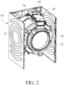
- FIG. 2 is another partial schematic perspective view of the laundry handling device in FIG. 1 .
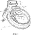
- FIG. 3 is a partial schematic exploded and perspective view of the laundry handling device in FIG. 1 . As shown in FIG. 1 , FIG. 2 , and FIG.
- a laundry handling device 10 including: a case 12, including a first opening 14; a laundry handling container 16, located in the case 12, and including a second opening 18 corresponding to the first opening 14; a circulating air channel 20, in fluid communication with the laundry handling container 16; a door seal assembly 22, connecting the first opening 14 and the second opening 18, the door seal assembly 22 including a third opening 24, and the third opening 24 being in fluid communication with the circulating air channel 20; and a filter screen assembly 26, arranged close to the third opening 24, the filter screen assembly 26 being detachably connected to the circulating air channel 20 and/or the door seal assembly 22, so as to filter air circulating between the circulating air channel 20 and the laundry handling container 16.
- the door seal assembly 22 connects the first opening 14 and the second opening 18, and the filter screen assembly 26 can be mounted or dismounted from the third opening 24 through the first opening 14, thereby facilitating user operation.
- Fluffs in the air circulating during the use of the laundry handling device 10 can stay in the filter screen assembly 26, to reduce or eliminate the possibility of accumulation or blockage in the circulating air channel 20, the door seal assembly 22, etc.
- the filter screen assembly 26 can be dismounted through the first opening 14 and the third opening 24 to clean the fluffs thereon.
- the cleaned filter screen assembly 26 can be mounted back into the laundry handling device 10 through the first opening 14 and the third opening 24 for reuse.
- orientations and relationships represented by words such as “inside”, “outside”, “front”, “rear”, “upper”, “lower”, “left”, and “right” in this text may refer to those shown in the accompanying drawings, or may correspond to the orientations and relationships in actual use of the laundry handling device 10.
- the laundry handling device 10 may be a washer-dryer combo, for example, a condenser washer-dryer combo.
- the case 12 may be a substantially cuboid including front, rear, left, right, upper, and lower walls.
- the laundry handling device 10 may include a door 13 arranged on the front wall of the case 12, which can open/close the first opening 14. In a case that the door 13 is opened, laundry to be handled (not shown) can be put into the laundry handling container 16 through the first opening 14 and the second opening 18 to be washed, dried, or handled in other ways, or the handled laundry (not shown) can be taken out from the laundry handling container 16 from the second opening 18 and the first opening 14.
- FIG. 1 a part above the position where the door 13 is located on the front wall of the case 12 is removed, so as to display the internal structure of the part of the laundry handling device 10.
- FIG. 2 the upper wall, the front wall, the door 14, and the lower wall of the case 12 are removed, so as to display the structures inside the laundry handling device 10, such as the laundry handling container 16 and the circulating air channel 20.
- Air in the circulating air channel 20 can enter the laundry handling container 16 from the third opening 24 and the second opening 18, so as to dry the laundry in the laundry handling container.
- the air in the laundry handling container 16 can flow back to the circulating air channel 20 to be heated and dehumidified, and then flow to the laundry handling container. The process proceeds in circles.
- the filter screen assembly 26 is magnetically connected to the circulating air channel 20 and/or the door seal assembly 22.
- the magnetic connection can facilitate dismounting and mounting the filter screen assembly 26 and sensing the dismounting and mounting of the filter screen assembly 26, thereby facilitating blind mounting, and achieving less limit by the visual range.
- the circulating air channel 20 and/or the door seal assembly 22 includes a first connecting part 28, the filter screen assembly 26 includes a second connecting part 30 matching the first connecting part 28, one of the first connecting part 28 and the second connecting part 30 includes a magnet, and the other of the first connecting part 28 and the second connecting part 30 includes a magnet or a ferromagnetic metal.
- the first connecting part 28 and the second connecting part 30 can be connected to each other through mutual attraction between the magnet and the magnet or between the magnet and the ferromagnetic metal.
- the magnetic connection can be broken using a separation force greater than the attraction force.
- the magnet may be a permanent magnet or an electromagnet.
- ferromagnetic metal examples include, but are not limited to, iron, nickel, and cobalt.
- the circulating air channel 20 includes a first bonding part 32
- the door seal assembly 22 includes a second bonding part 34 bonded to the first bonding part 32
- the first bonding part 32 is adjacent to the first connecting part 28.
- the first bonding part 32 and the second bonding pat 34 may be bonded to each other in a receiving manner that the inner side receives the outer side.
- the first connecting part 28 may be arranged on the inner side of the first bonding part 32 and/or the second bonding part 34.
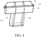
- FIG. 4 is a schematic perspective view of a filter screen assembly of the laundry handling device in FIG. 1 .
- the filter screen assembly 26 includes a filter screen frame 36 at least partially received in the circulating air channel 20 and/or the door seal assembly 22 and a filter screen 38 connected to the filter screen frame 36.
- the filter screen frame 36 is at least partially received in the circulating air channel 20 and/or the door seal assembly 22, which is beneficial to occupying less or even no space in other parts of the laundry handling device 10, and thus avoiding excessive influence on the spatial arrangement of the laundry handling device 10.
- the filter screen 38 can intercept and filter fluffs carried in the air passing through the filter screen, thereby reducing or eliminating the possibility of fluff accumulation and blockage in other parts.
- an edge portion of the filter screen 38 is fixed to the filter screen frame 36, and a middle portion of the filter screen 38 extends from the filter screen frame 36 to a circulating air flow direction.
- the convex direction of the filter screen 38 is along the circulating air flow direction, which is beneficial to concentrating the intercepted fluffs in the filter screen 38 to facilitate cleaning.
- the filter screen frame 36 can support and fix the filter screen 38.
- the filter screen 38 can intercept and filter fluffs carried in the circulating air passing through the filter screen, thereby reducing or eliminating the possibility of fluff accumulation and blockage in other parts.
- the circulating air channel 20 and/or the door seal assembly 22 includes a first connecting part 28, the filter screen assembly 26 includes a second connecting part 30 matching the first connecting part 28, and the second connecting part 30 is arranged on the filter screen frame 36.
- the filter screen frame 36 can fit with the circulating air channel 20 and/or the door seal assembly 22 by the second connecting part 30 so as to be mounted and fixed.
- the filter screen assembly 26 includes a handle part 40 extending from the filter screen frame 36 to the direction of the third opening 24.
- the handle part 40 can be held or clamped to move the filter screen assembly 26 toward the circulating air channel 20 and/or the door seal assembly 22 from the third opening 24 for connecting and mounting.
- the handle part 40 can be held or clamped to separate the filter screen assembly 26 from the circulating air channel 20 and/or the door seal assembly 22 and take out the filter screen assembly from the third opening 24.
- the handle part 40 is narrower than the filter screen 38.
- the handle part 40 can extend out from an approximately middle portion of one edge of the filter screen frame 36, and may be narrower than the filter screen 38 on both sides, so as to reduce the space occupied, reduce obstruction to air, and reduce the possibility of unnecessary contact with other components.
- the handle part 40 is fitted to a wall of the circulating air channel 20 and/or the door seal assembly 22.
- the handle part 40 does not extend out of the third opening 24.
- the size of the filter screen frame 36 is adapted to the size of the circulating air channel 20 and/or the door seal assembly 22 at the mounting position of the filter screen frame.
- the door seal assembly 22 includes an air channel 42 extending out from the third opening 24 to the direction of the circulating air channel 20 and connected to the circulating air channel 20, and the filter screen assembly 26 is at least partially received in the air channel 42.
- the door seal assembly 22 may be in the shape of an approximate cylinder having front and rear ends open.
- the third opening 24 can be arranged on an upper wall portion of the door seal assembly 22, in fluid communication with the circulating air channel 20 through the air channel 42, and communicated with the circulating air channel 20 and the laundry handling container 16 through the second opening 18.
- the shape, structure, and size of the air channel 42 may correspond to those of the circulating air channel 20, and the air channel may have an approximately square tubular shape.
- the second bonding part 34 may be arranged at an end portion of the air channel 42 close to the circulating air channel 20. Accordingly, the first bonding part 32 may be arranged at the end portion of the circulating air channel 20 close to the air channel 42.
- the laundry handling device 10 includes a blower device 44 for promoting air to circulate and communicate between the circulating air channel 20 and the laundry handling container 16.
- the blower device 44 may be connected to the circulating air channel 20.
- the portion of the circulating air channel 20 connected to the blower device 44 and the portion of the circulating air channel connected to the air channel 42 may be at a certain angle, for example, perpendicular to each other.
- the blower device 44 may be arranged behind the circulating air channel 20 and the door seal assembly 22.
- the door seal assembly 22 may be arranged below the blower device 44 and the circulating air channel 20.
- the laundry handling container 16 may be arranged below the blower device 44 and the circulating air channel 20, and behind the door seal assembly 22.
Landscapes
- Engineering & Computer Science (AREA)
- Textile Engineering (AREA)
- Detail Structures Of Washing Machines And Dryers (AREA)
Abstract
Description
- The present disclosure relates to the technical field of laundry handling, and in particular to a laundry handling device.
- Fluffs in the air circulating in some existing laundry handling devices may accumulate and are difficult to clean up. As a result, the laundry handling devices need to be improved.
- The purpose of the present disclosure is to solve, for example, at least one of the problems above.
- For the foregoing purpose, one aspect of embodiments of the present disclosure relates to a laundry handling device, including: a case, including a first opening; a laundry handling container, located in the case, and including a second opening corresponding to the first opening; a circulating air channel, in fluid communication with the laundry handling container; a door seal assembly, connecting the first opening and the second opening, the door seal assembly including a third opening, and the third opening being in fluid communication with the circulating air channel; and a filter screen assembly, arranged close to the third opening, the filter screen assembly being detachably connected to the circulating air channel and/or the door seal assembly, so as to filter air circulating between the circulating air channel and the laundry handling container.
- In this way, it is beneficial to facilitating cleaning of fluffs carried in the air circulating in the laundry handling device, and reducing or eliminating the possibility of fluff accumulation.
- Optionally, the filter screen assembly is magnetically connected to the circulating air channel and/or the door seal assembly. In this way, it is beneficial to conveniently mounting and dismounting the filter screen assembly.
- Optionally, the circulating air channel and/or the door seal assembly includes a first connecting part, the filter screen assembly includes a second connecting part matching the first connecting part, one of the first connecting part and the second connecting part includes a magnet, and the other of the first connecting part and the second connecting part includes a magnet or a ferromagnetic metal.
- In this way, it is beneficial to conveniently mounting and dismounting the filter screen assembly.
- Optionally, the circulating air channel includes a first bonding part, the door seal assembly includes a second bonding part bonded to the first bonding part, and the first bonding part is adjacent to the first connecting part. In this way, it is beneficial to processing and assembling the laundry handling device simply and conveniently.
- Optionally, the filter screen assembly includes a filter screen frame at least partially received in the circulating air channel and/or the door seal assembly and a filter screen connected to the filter screen frame.
- In this way, it is beneficial to effectively utilizing the space of the laundry handling device, facilitating cleaning of fluffs, and reducing or eliminating the possibility of fluff accumulation.
- Optionally, an edge portion of the filter screen is fixed to the filter screen frame, and a middle portion of the filter screen extends from the filter screen frame to a circulating air flow direction.
- In this way, it is beneficial to increasing the filtering area of the filter screen assembly.
- Optionally, the circulating air channel and/or the door seal assembly includes a first connecting part, the filter screen assembly includes a second connecting part matching the first connecting part, and the second connecting part is arranged on the filter screen frame.
- In this way, it is beneficial to guaranteeing the filtering area of the filter screen assembly.
- Optionally, the filter screen assembly includes a handle part extending from the filter screen frame to the direction of the third opening.
- In this way, it is beneficial to conveniently mounting and dismounting the filter screen assembly from the direction of the third opening. Optionally, the handle part is narrower than the filter screen.
- In this way, it is beneficial to reducing or avoiding the influence of air circulation, and facilitating mounting and dismounting of the filter screen assembly.
- Optionally, the handle part is fitted to a wall of the circulating air channel and/or the door seal assembly. In this way, it is beneficial to reducing or avoiding the influence of air circulation.
- Optionally, the handle part does not extend out of the third opening.
- In this way, it is beneficial to achieving attractive appearance and a compact structure of the laundry handling device.
- Optionally, the size of the filter screen frame is adapted to the size of the circulating air channel and/or the door seal assembly at the mounting position of the filter screen frame.
- In this way, it is beneficial to achieving firm bonding between the filter screen frame and the circulating air channel and/or the door seal assembly, and guaranteeing the filtering area of the filter screen assembly.
- Optionally, the door seal assembly includes an air channel extending out from the third opening to the direction of the circulating air channel and connected to the circulating air channel, and the filter screen assembly is at least partially received in the air channel.
- In this way, it is beneficial to achieving attractive appearance and a compact structure of the laundry handling device.
- Optionally, the laundry handling device includes a blower device for promoting air to circulate and communicate between the circulating air channel and the laundry handling container.
- In this way, it is beneficial to promoting circulation of air inside the laundry handling device.
- If technical conditions permit, the technical solutions of the foregoing embodiments can be combined arbitrarily. The present disclosure is further described below in combination with the accompanying drawings. The same or similar reference numerals may be used in the drawings to refer to the same or similar elements, shapes, configurations, features, etc. in different embodiments, and the same or similar elements, shapes, configurations, features, effects, etc. in different embodiments and existing elements, shapes, configurations, features, effects, etc. in the related art may be omitted.
-
FIG. 1 is a partial schematic perspective view of a laundry handling device according to one aspect of embodiments of the present disclosure. -
FIG. 2 is another partial schematic perspective view of the laundry handling device inFIG. 1 . -
FIG. 3 is a partial schematic exploded and perspective view of the laundry handling device inFIG. 1 . -
FIG. 4 is a schematic perspective view of a filter screen assembly of the laundry handling device inFIG. 1 . -
FIG. 1 is a partial schematic perspective view of a laundry handling device according to one aspect of embodiments of the present disclosure.FIG. 2 is another partial schematic perspective view of the laundry handling device inFIG. 1 .FIG. 3 is a partial schematic exploded and perspective view of the laundry handling device inFIG. 1 . As shown inFIG. 1 ,FIG. 2 , andFIG. 3 , one aspect of embodiments of the present disclosure relates to alaundry handling device 10, including: acase 12, including afirst opening 14; alaundry handling container 16, located in thecase 12, and including asecond opening 18 corresponding to thefirst opening 14; a circulatingair channel 20, in fluid communication with thelaundry handling container 16; adoor seal assembly 22, connecting thefirst opening 14 and thesecond opening 18, thedoor seal assembly 22 including a third opening 24, and the third opening 24 being in fluid communication with the circulatingair channel 20; and afilter screen assembly 26, arranged close to the third opening 24, thefilter screen assembly 26 being detachably connected to the circulatingair channel 20 and/or thedoor seal assembly 22, so as to filter air circulating between the circulatingair channel 20 and thelaundry handling container 16. - In this way, it is beneficial to facilitating cleaning of fluffs carried in the air circulating in the
laundry handling device 10, and reducing or eliminating the possibility of fluff accumulation. - For example, the
door seal assembly 22 connects thefirst opening 14 and thesecond opening 18, and thefilter screen assembly 26 can be mounted or dismounted from the third opening 24 through thefirst opening 14, thereby facilitating user operation. Fluffs in the air circulating during the use of thelaundry handling device 10 can stay in thefilter screen assembly 26, to reduce or eliminate the possibility of accumulation or blockage in the circulatingair channel 20, thedoor seal assembly 22, etc. Thefilter screen assembly 26 can be dismounted through thefirst opening 14 and the third opening 24 to clean the fluffs thereon. The cleanedfilter screen assembly 26 can be mounted back into thelaundry handling device 10 through thefirst opening 14 and the third opening 24 for reuse. - The words "first", "second", and "third" in this text do not intend to represent the priority, importance or the like, but only intend to help distinguish each other.
- The orientations and relationships represented by words such as "inside", "outside", "front", "rear", "upper", "lower", "left", and "right" in this text may refer to those shown in the accompanying drawings, or may correspond to the orientations and relationships in actual use of the
laundry handling device 10. - The
laundry handling device 10 may be a washer-dryer combo, for example, a condenser washer-dryer combo. Thecase 12 may be a substantially cuboid including front, rear, left, right, upper, and lower walls. Thelaundry handling device 10 may include adoor 13 arranged on the front wall of thecase 12, which can open/close thefirst opening 14. In a case that thedoor 13 is opened, laundry to be handled (not shown) can be put into thelaundry handling container 16 through thefirst opening 14 and the second opening 18 to be washed, dried, or handled in other ways, or the handled laundry (not shown) can be taken out from thelaundry handling container 16 from the second opening 18 and thefirst opening 14. - In
FIG. 1 , a part above the position where thedoor 13 is located on the front wall of thecase 12 is removed, so as to display the internal structure of the part of thelaundry handling device 10. InFIG. 2 , the upper wall, the front wall, thedoor 14, and the lower wall of thecase 12 are removed, so as to display the structures inside thelaundry handling device 10, such as thelaundry handling container 16 and the circulatingair channel 20. - Air in the circulating
air channel 20 can enter thelaundry handling container 16 from the third opening 24 and the second opening 18, so as to dry the laundry in the laundry handling container. The air in thelaundry handling container 16 can flow back to the circulatingair channel 20 to be heated and dehumidified, and then flow to the laundry handling container. The process proceeds in circles. - Optionally, the
filter screen assembly 26 is magnetically connected to the circulatingair channel 20 and/or thedoor seal assembly 22. - In this way, it is beneficial to conveniently mounting and dismounting the
filter screen assembly 26. - The magnetic connection can facilitate dismounting and mounting the
filter screen assembly 26 and sensing the dismounting and mounting of thefilter screen assembly 26, thereby facilitating blind mounting, and achieving less limit by the visual range. - Optionally, the circulating
air channel 20 and/or thedoor seal assembly 22 includes a first connecting part 28, thefilter screen assembly 26 includes a second connectingpart 30 matching the first connecting part 28, one of the first connecting part 28 and the second connectingpart 30 includes a magnet, and the other of the first connecting part 28 and the second connectingpart 30 includes a magnet or a ferromagnetic metal. - In this way, it is beneficial to conveniently mounting and dismounting the
filter screen assembly 26. - Therefore, the first connecting part 28 and the second connecting
part 30 can be connected to each other through mutual attraction between the magnet and the magnet or between the magnet and the ferromagnetic metal. The magnetic connection can be broken using a separation force greater than the attraction force. The magnet may be a permanent magnet or an electromagnet. - Examples of the ferromagnetic metal include, but are not limited to, iron, nickel, and cobalt.
- Optionally, the circulating
air channel 20 includes afirst bonding part 32, thedoor seal assembly 22 includes asecond bonding part 34 bonded to thefirst bonding part 32, and thefirst bonding part 32 is adjacent to the first connecting part 28. - In this way, it is beneficial to processing and assembling the
laundry handling device 10 simply and conveniently. - The
first bonding part 32 and thesecond bonding pat 34 may be bonded to each other in a receiving manner that the inner side receives the outer side. The first connecting part 28 may be arranged on the inner side of thefirst bonding part 32 and/or thesecond bonding part 34. -
FIG. 4 is a schematic perspective view of a filter screen assembly of the laundry handling device inFIG. 1 . Referring toFIG. 4 , optionally, thefilter screen assembly 26 includes afilter screen frame 36 at least partially received in the circulatingair channel 20 and/or thedoor seal assembly 22 and afilter screen 38 connected to thefilter screen frame 36. - In this way, it is beneficial to effectively utilizing the space of the
laundry handling device 10, facilitating cleaning of fluffs, and reducing or eliminating the possibility of fluff accumulation. - The
filter screen frame 36 is at least partially received in the circulatingair channel 20 and/or thedoor seal assembly 22, which is beneficial to occupying less or even no space in other parts of thelaundry handling device 10, and thus avoiding excessive influence on the spatial arrangement of thelaundry handling device 10. Thefilter screen 38 can intercept and filter fluffs carried in the air passing through the filter screen, thereby reducing or eliminating the possibility of fluff accumulation and blockage in other parts. - Optionally, an edge portion of the
filter screen 38 is fixed to thefilter screen frame 36, and a middle portion of thefilter screen 38 extends from thefilter screen frame 36 to a circulating air flow direction. - Compared with planar filter screen structures, it is beneficial to increasing the filtering area of the
filter screen assembly 26. The convex direction of thefilter screen 38 is along the circulating air flow direction, which is beneficial to concentrating the intercepted fluffs in thefilter screen 38 to facilitate cleaning. - The
filter screen frame 36 can support and fix thefilter screen 38. Thefilter screen 38 can intercept and filter fluffs carried in the circulating air passing through the filter screen, thereby reducing or eliminating the possibility of fluff accumulation and blockage in other parts. - Optionally, the circulating
air channel 20 and/or thedoor seal assembly 22 includes a first connecting part 28, thefilter screen assembly 26 includes a second connectingpart 30 matching the first connecting part 28, and the second connectingpart 30 is arranged on thefilter screen frame 36. - In this way, it is beneficial to guaranteeing the filtering area of the
filter screen assembly 26. - The
filter screen frame 36 can fit with the circulatingair channel 20 and/or thedoor seal assembly 22 by the second connectingpart 30 so as to be mounted and fixed. - Optionally, the
filter screen assembly 26 includes ahandle part 40 extending from thefilter screen frame 36 to the direction of thethird opening 24. - In this way, it is beneficial to conveniently mounting and dismounting the
filter screen assembly 26 from the direction of thethird opening 24. - For example, the
handle part 40 can be held or clamped to move thefilter screen assembly 26 toward the circulatingair channel 20 and/or thedoor seal assembly 22 from thethird opening 24 for connecting and mounting. - The
handle part 40 can be held or clamped to separate thefilter screen assembly 26 from the circulatingair channel 20 and/or thedoor seal assembly 22 and take out the filter screen assembly from thethird opening 24. - Optionally, the
handle part 40 is narrower than thefilter screen 38. - In this way, it is beneficial to reducing or avoiding the influence of air circulation, and facilitating mounting and dismounting of the
filter screen assembly 26. - The
handle part 40 can extend out from an approximately middle portion of one edge of thefilter screen frame 36, and may be narrower than thefilter screen 38 on both sides, so as to reduce the space occupied, reduce obstruction to air, and reduce the possibility of unnecessary contact with other components. - Optionally, the
handle part 40 is fitted to a wall of the circulatingair channel 20 and/or thedoor seal assembly 22. - In this way, it is beneficial to reducing or avoiding the influence of air circulation. Optionally, the
handle part 40 does not extend out of thethird opening 24. - In this way, it is beneficial to achieving attractive appearance and a compact structure of the
laundry handling device 10, reducing the influence on other elements of thelaundry handling device 10, and avoiding that, during the operation of thelaundry handling device 10, thehandle part 40 is squeezed and pulled by the laundry and then thefilter screen assembly 26 falls off from the mounting position. - Optionally, the size of the
filter screen frame 36 is adapted to the size of the circulatingair channel 20 and/or thedoor seal assembly 22 at the mounting position of the filter screen frame. - In this way, it is beneficial to achieving firm bonding between the
filter screen frame 36 and the circulatingair channel 20 and/or thedoor seal assembly 22, and guaranteeing the filtering area of thefilter screen assembly 26. - Continue to refer to
FIG. 3 . optionally, thedoor seal assembly 22 includes anair channel 42 extending out from thethird opening 24 to the direction of the circulatingair channel 20 and connected to the circulatingair channel 20, and thefilter screen assembly 26 is at least partially received in theair channel 42. - In this way, it is beneficial to achieving attractive appearance and a compact structure of the
laundry handling device 10. - The
door seal assembly 22 may be in the shape of an approximate cylinder having front and rear ends open. Thethird opening 24 can be arranged on an upper wall portion of thedoor seal assembly 22, in fluid communication with the circulatingair channel 20 through theair channel 42, and communicated with the circulatingair channel 20 and thelaundry handling container 16 through thesecond opening 18. The shape, structure, and size of theair channel 42 may correspond to those of the circulatingair channel 20, and the air channel may have an approximately square tubular shape. Thesecond bonding part 34 may be arranged at an end portion of theair channel 42 close to the circulatingair channel 20. Accordingly, thefirst bonding part 32 may be arranged at the end portion of the circulatingair channel 20 close to theair channel 42. - Optionally, the
laundry handling device 10 includes ablower device 44 for promoting air to circulate and communicate between the circulatingair channel 20 and thelaundry handling container 16. - In this way, it is beneficial to promoting circulation of air inside the
laundry handling device 10. - The
blower device 44 may be connected to the circulatingair channel 20. The portion of the circulatingair channel 20 connected to theblower device 44 and the portion of the circulating air channel connected to theair channel 42 may be at a certain angle, for example, perpendicular to each other. Theblower device 44 may be arranged behind the circulatingair channel 20 and thedoor seal assembly 22. Thedoor seal assembly 22 may be arranged below theblower device 44 and the circulatingair channel 20. Thelaundry handling container 16 may be arranged below theblower device 44 and the circulatingair channel 20, and behind thedoor seal assembly 22. - The various specific implementations described above and shown in the accompanying drawings are only used to illustrate the present disclosure, but do not refer to all of the present disclosure. Within the scope of the basic technical idea of the present disclosure, any form of modification made by a person skilled in the art to the present disclosure falls within the scope of protection of the present disclosure.
Claims (14)
- A laundry handling device (10), the device comprising:a case (12), comprising a first opening (14);a laundry handling container (16), located in the case (12), and comprising a second opening (18) corresponding to the first opening (14);a circulating air channel (20), in fluid communication with the laundry handling container (16);a door seal assembly (22), connecting the first opening (14) and the second opening (18), the door seal assembly (22) comprising a third opening (24), and the third opening (24) being in fluid communication with the circulating air channel (20); anda filter screen assembly (26), arranged close to the third opening (24), the filter screen assembly (26) being detachably connected to the circulating air channel (20) and/or the door seal assembly (22), so as to filter air circulating between the circulating air channel (20) and the laundry handling container (16).
- The laundry handling device (10) according to claim 1, wherein the filter screen assembly (26) is magnetically connected to the circulating air channel (20) and/or the door seal assembly (22).
- The laundry handling device (10) according to claim 1, wherein the circulating air channel (20) and/or the door seal assembly (22) comprises a first connecting part (28), the filter screen assembly (26) comprises a second connecting part (30) matching the first connecting part (28), one of the first connecting part (28) and the second connecting part (30) comprises a magnet, and the other of the first connecting part (28) and the second connecting part (30) comprises a magnet or a ferromagnetic metal.
- The laundry handling device (10) according to claim 3, wherein the circulating air channel (20) comprises a first bonding part (32), the door seal assembly (22) comprises a second bonding part (34) bonded to the first bonding part (32), and the first bonding part (32) is adjacent to the first connecting part (28).
- The laundry handling device (10) according to claim 1, wherein the filter screen assembly (26) comprises a filter screen frame (36) at least partially received in the circulating air channel (20) and/or the door seal assembly (22) and a filter screen (38) connected to the filter screen frame (36).
- The laundry handling device (10) according to claim 5, wherein an edge portion of the filter screen (38) is fixed to the filter screen frame (36), and a middle portion of the filter screen (38) extends from the filter screen frame (36) to a circulating airflow direction.
- The laundry handling device (10) according to claim 5, wherein the circulating air channel (20) and/or the door seal assembly (22) comprises a first connecting part (28), the filter screen assembly (26) comprises a second connecting part (30) matching the first connecting part (28), and the second connecting part (30) is arranged on the filter screen frame (36).
- The laundry handling device (10) according to claim 5, wherein the filter screen assembly (26) comprises a handle part (40) extending from the filter screen frame (36) to the direction of the third opening (24).
- The laundry handling device (10) according to claim 8, wherein the handle part (40) is narrower than the filter screen (38).
- The laundry handling device (10) according to claim 8, wherein the handle part (40) is fitted to a wall of the circulating air channel (20) and/or the door seal assembly (22).
- The laundry handling device (10) according to claim 8, wherein the handle part (40) does not extend out of the third opening (24).
- The laundry handling device (10) according to claim 5, wherein the size of the filter screen frame (36) is adapted to the size of the circulating air channel (20) and/or the door seal assembly (22) at the mounting position of the filter screen frame.
- The laundry handling device (10) according to claim 1, wherein the door seal assembly (22) comprises an air channel (42) extending out from the third opening (24) to the direction of the circulating air channel (20) and connected to the circulating air channel (20), and the filter screen assembly (26) is at least partially received in the air channel (42).
- The laundry handling device (10) according to any one of claims 1 to 13, comprising a blower device (44) for promoting air to circulate and communicate between the circulating air channel (20) and the laundry handling container (16).
Applications Claiming Priority (1)
| Application Number | Priority Date | Filing Date | Title |
|---|---|---|---|
| CN202111359743.4A CN116136046A (en) | 2021-11-17 | 2021-11-17 | Clothes treatment device |
Publications (1)
| Publication Number | Publication Date |
|---|---|
| EP4183915A1 true EP4183915A1 (en) | 2023-05-24 |
Family
ID=83996641
Family Applications (1)
| Application Number | Title | Priority Date | Filing Date |
|---|---|---|---|
| EP22203830.9A Pending EP4183915A1 (en) | 2021-11-17 | 2022-10-26 | Laundry handling device |
Country Status (2)
| Country | Link |
|---|---|
| EP (1) | EP4183915A1 (en) |
| CN (1) | CN116136046A (en) |
Citations (2)
| Publication number | Priority date | Publication date | Assignee | Title |
|---|---|---|---|---|
| EP2273005A2 (en) * | 2009-06-29 | 2011-01-12 | Miele & Cie. KG | Tumble dryer |
| EP2843121A1 (en) * | 2013-08-28 | 2015-03-04 | Electrolux Appliances Aktiebolag | Laundry dryer apparatus |
-
2021
- 2021-11-17 CN CN202111359743.4A patent/CN116136046A/en active Pending
-
2022
- 2022-10-26 EP EP22203830.9A patent/EP4183915A1/en active Pending
Patent Citations (2)
| Publication number | Priority date | Publication date | Assignee | Title |
|---|---|---|---|---|
| EP2273005A2 (en) * | 2009-06-29 | 2011-01-12 | Miele & Cie. KG | Tumble dryer |
| EP2843121A1 (en) * | 2013-08-28 | 2015-03-04 | Electrolux Appliances Aktiebolag | Laundry dryer apparatus |
Also Published As
| Publication number | Publication date |
|---|---|
| CN116136046A (en) | 2023-05-19 |
Similar Documents
| Publication | Publication Date | Title |
|---|---|---|
| CN210990037U (en) | Dust Boxes, Dust Box Components and Cleaning Units | |
| CN211484410U (en) | Dust Boxes, Dust Box Components and Cleaning Units | |
| US6526773B1 (en) | Air conditioner | |
| EP4183915A1 (en) | Laundry handling device | |
| EP2185051B1 (en) | A detachable filter insert for a vacuum cleaner | |
| JP2002291663A (en) | Electric vacuum cleaner | |
| EP4137634A1 (en) | Foreign particulate removal assembly of a laundry appliance | |
| CN211704535U (en) | Filter mounting structure and feeding bottle cleaning machine thereof | |
| CN210569130U (en) | Air cooler dust keeper and set up its air cooler | |
| US12618189B2 (en) | Lint filter for laundry appliance having a closable filtering space for capturing lint particles | |
| KR100751764B1 (en) | Exhaust filter for vacuum cleaner | |
| KR100692577B1 (en) | Filter detection device for vacuum cleaner | |
| ES2259510A1 (en) | AIR DISCHARGE STRUCTURE FOR A VACUUM CLEANER. | |
| CN222911884U (en) | Filter assembly and air conditioner | |
| CN223983867U (en) | Door body structure and clothes treatment equipment | |
| EP4265836A1 (en) | Lint filter for laundry appliance having a closable filtering space for capturing lint particles | |
| CN214009308U (en) | Fume exhaust fan | |
| KR100246900B1 (en) | Airconditioner | |
| CN216092710U (en) | Filter screen assembly | |
| CN216052891U (en) | Dampproofing quick-witted case of good heat dissipation | |
| KR100246898B1 (en) | Air conditioner | |
| KR100225635B1 (en) | Indoor unit for wall-mounted air conditioner | |
| KR20040018200A (en) | Air conditioner | |
| JPS581704Y2 (en) | Air conditioner filter mounting structure | |
| KR100436143B1 (en) | Indoor unit of air conditioner |
Legal Events
| Date | Code | Title | Description |
|---|---|---|---|
| PUAI | Public reference made under article 153(3) epc to a published international application that has entered the european phase |
Free format text: ORIGINAL CODE: 0009012 |
|
| STAA | Information on the status of an ep patent application or granted ep patent |
Free format text: STATUS: THE APPLICATION HAS BEEN PUBLISHED |
|
| AK | Designated contracting states |
Kind code of ref document: A1 Designated state(s): AL AT BE BG CH CY CZ DE DK EE ES FI FR GB GR HR HU IE IS IT LI LT LU LV MC ME MK MT NL NO PL PT RO RS SE SI SK SM TR |
|
| STAA | Information on the status of an ep patent application or granted ep patent |
Free format text: STATUS: REQUEST FOR EXAMINATION WAS MADE |
|
| 17P | Request for examination filed |
Effective date: 20231124 |
|
| RBV | Designated contracting states (corrected) |
Designated state(s): AL AT BE BG CH CY CZ DE DK EE ES FI FR GB GR HR HU IE IS IT LI LT LU LV MC ME MK MT NL NO PL PT RO RS SE SI SK SM TR |
|
| STAA | Information on the status of an ep patent application or granted ep patent |
Free format text: STATUS: EXAMINATION IS IN PROGRESS |
|
| 17Q | First examination report despatched |
Effective date: 20250630 |