EP4183663A1 - Steer-by-wire system and steering control method - Google Patents
Steer-by-wire system and steering control method Download PDFInfo
- Publication number
- EP4183663A1 EP4183663A1 EP20946476.7A EP20946476A EP4183663A1 EP 4183663 A1 EP4183663 A1 EP 4183663A1 EP 20946476 A EP20946476 A EP 20946476A EP 4183663 A1 EP4183663 A1 EP 4183663A1
- Authority
- EP
- European Patent Office
- Prior art keywords
- steering
- slide
- wheel
- rotation angle
- steering wheel
- Prior art date
- Legal status (The legal status is an assumption and is not a legal conclusion. Google has not performed a legal analysis and makes no representation as to the accuracy of the status listed.)
- Granted
Links
Images





Classifications
-
- B—PERFORMING OPERATIONS; TRANSPORTING
- B62—LAND VEHICLES FOR TRAVELLING OTHERWISE THAN ON RAILS
- B62D—MOTOR VEHICLES; TRAILERS
- B62D5/00—Power-assisted or power-driven steering
- B62D5/04—Power-assisted or power-driven steering electrical, e.g. using an electric servo-motor connected to, or forming part of, the steering gear
- B62D5/0457—Power-assisted or power-driven steering electrical, e.g. using an electric servo-motor connected to, or forming part of, the steering gear characterised by control features of the drive means as such
- B62D5/046—Controlling the motor
- B62D5/0469—End-of-stroke control
-
- B—PERFORMING OPERATIONS; TRANSPORTING
- B62—LAND VEHICLES FOR TRAVELLING OTHERWISE THAN ON RAILS
- B62D—MOTOR VEHICLES; TRAILERS
- B62D5/00—Power-assisted or power-driven steering
- B62D5/001—Mechanical components or aspects of steer-by-wire systems, not otherwise provided for in this maingroup
-
- B—PERFORMING OPERATIONS; TRANSPORTING
- B62—LAND VEHICLES FOR TRAVELLING OTHERWISE THAN ON RAILS
- B62D—MOTOR VEHICLES; TRAILERS
- B62D5/00—Power-assisted or power-driven steering
- B62D5/04—Power-assisted or power-driven steering electrical, e.g. using an electric servo-motor connected to, or forming part of, the steering gear
- B62D5/0409—Electric motor acting on the steering column
- B62D5/0412—Electric motor acting on the steering column the axes of motor and steering column being parallel
- B62D5/0415—Electric motor acting on the steering column the axes of motor and steering column being parallel the axes being coaxial
-
- B—PERFORMING OPERATIONS; TRANSPORTING
- B62—LAND VEHICLES FOR TRAVELLING OTHERWISE THAN ON RAILS
- B62D—MOTOR VEHICLES; TRAILERS
- B62D5/00—Power-assisted or power-driven steering
- B62D5/001—Mechanical components or aspects of steer-by-wire systems, not otherwise provided for in this maingroup
- B62D5/003—Backup systems, e.g. for manual steering
Definitions
- This application relates to the field of vehicle steering technologies, and in particular, to a steer-by-wire system and a steering control method.
- a steer-by-wire system is a system for controlling vehicle steering by using an electrical signal, and a mechanical connection apparatus between a steering wheel and a steerable wheel is canceled.
- the steer-by-wire system mainly includes a steering controller, a steering driving motor, a steering wheel, a steering column, and the like.
- An output shaft of the steering driving motor is connected to the steerable wheel through rotation.
- the steering wheel is installed at an end of the steering column.
- the steering column has a sensor for collecting a rotation angle and torque of the steering wheel. In this way, when a driver operates the steering wheel, the steering controller may obtain the rotation angle and torque of the steering wheel by using the sensor, and then may control, based on the rotation angle and torque of the steering wheel, the steering driving motor to drive the steerable wheel to steer.
- the steerable wheel has a rotation range, when rotating to a limit position, the steerable wheel cannot continue to rotate, but the steering wheel can rotate without a limitation. In this way, a rotation range of the steering wheel may be inconsistent with the rotation range of the steerable wheel, which affects operation and control of the driver on vehicle steering.
- This application provides a steer-by-wire system and a steering control method, to overcome a problem in the conventional technology that a steerable wheel has a rotation range limitation but a steering wheel does not have a rotation range limitation.
- Technical solutions are as follows.
- a steer-by-wire system where the steer-by-wire system includes a steering column and a limiting apparatus.
- the limiting apparatus includes a fixed rod, a slide block, and a movable limiting block.
- the slide block is located on the fixed rod, and the slide block can slide on the fixed rod as the steering column rotates.
- the movable limiting block is located on the fixed rod, and can slide on the fixed rod, to limit the slide block to slide on the fixed rod. Therefore, the steering column rotates within a target rotation range.
- the steer-by-wire system may further include a steering wheel.
- the steering wheel is fixed at an end of the steering column.
- the steering column may synchronously rotate with the steering wheel.
- the steering wheel when the steering wheel rotates, the steering column can be driven to synchronously rotate; and when the steering column rotates, the steering wheel can also be driven to synchronously rotate, so that a rotation angle of the steering column may be used to represent a rotation angle of the steering wheel, and torque of the steering column may also be used to represent torque of the steering wheel. Therefore, in this specification, the rotation angle of the steering column may be equivalent to the rotation angle of the steering wheel, and a rotation range of the steering column may be equivalent to a rotation range of the steering wheel.
- a rotation angle sensor and a torque sensor may be installed on the steering column.
- the torque sensor and the rotation angle sensor are installed on the steering column.
- the torque sensor can collect torque generated during rotation of the steering column.
- the rotation angle sensor can collect a rotation angle generated during rotation of the steering column.
- the torque and the rotation angle of the steering column may be respectively used as the torque and the rotation angle of the steering wheel.
- a steering driving motor of the steer-by-wire system is connected to a steerable wheel of a vehicle.
- the steerable wheel may be a left front wheel and a right front wheel of the vehicle.
- a steering controller of the steer-by-wire system may control a steering driving apparatus to drive the steerable wheel to steer, to implement wire control steering of the vehicle.
- the steer-by-wire system further includes the limiting apparatus.
- the limiting apparatus may limit the rotation of the steering wheel through sliding of the slide block and the movable limiting block on the fixed rod and a rotation connection between the slide block and the steering column, so that the steering wheel rotates within a target rotation range.
- the target rotation range is obtained through calculation based on a traveling parameter of a vehicle in which the steer-by-wire system is located.
- the steer-by-wire system may use the limiting apparatus to limit the rotation of the steering wheel, so that the steering wheel no longer rotates without a limitation, but rotates within the target rotation range corresponding to the rotation range of the steerable wheel.
- the rotation range of the steering wheel is consistent with the rotation range of the steerable wheel. Therefore, when the steerable wheel rotates to a limit position, the steering wheel also rotates to a limit position. This facilitates operation and control of a driver on vehicle steering, and facilitates driving safety.
- the limiting apparatus further includes a gear.
- the gear is sleeved on the steering column and synchronously rotates with the steering column.
- the slide block has a rack that engages with the gear.
- the slide block engages with the gear. When the gear rotates with the steering column, the gear pushes the slide block to slide on the fixed rod.
- the slide block is sleeved on the fixed rod, an outer wall of the slide block engages with the gear, and the gear is sleeved on the steering column and can move synchronously with the steering column.
- the gear engages with the slide block, the slide block can be pushed to slide on the fixed rod when the gear rotates.
- the gear may be pushed to rotate.
- the gear and the steering column synchronously rotate, thereby implementing a rotation connection between the slide block and the steering column.
- the rotation connection between the slide block and the steering column means that rotation of the steering column can be driven when the slide block slides and moves on the fixed rod, and that rotation of the steering column can also drive the slide block to slide and move on the fixed rod.
- a slide range of the slide block on the fixed rod may be limited to limit a rotation range of the steering column.
- the rotation range of the steering column may be used to represent the rotation range of the steering wheel, so that sliding of the slide block may be limited, to limit the rotation range of the steering wheel.
- the movable limiting block When sliding to be in contact with the slide block, the movable limiting block can be locked on the fixed rod, to limit sliding of the slide block, so that the slide block cannot continue to slide in a direction toward the movable limiting block. It can be learned that the movable limiting block can limit the slide range of the slide block.
- the rotation range of the steering column is limited. The steering column synchronously rotates with the steering wheel, so that the rotation range of the steering wheel is also limited.
- the movable limiting block of the limiting apparatus may limit the slide range of the slide block to further limit the rotation range of the steering wheel, so that the steering wheel rotates within the target rotation range.
- the fixed rod is a screw
- both the slide block and the movable limiting block are ball nuts. Both the slide block and the movable limiting block are sleeved on the fixed rod. The slide block and the movable limiting block can spirally slide on the fixed rod.
- Both the slide block and the movable limiting block are ball nuts, and the fixed rod is a screw.
- the slide block spirally slides on the screw
- the movable limiting block spirally slides on the screw.
- a ball is in a spiral groove of the slide block, and a ball is in a spiral groove of the movable limiting block, to reduce wear between the slide block and the fixed rod, reduce wear between the movable limiting block and the fixed rod, and prolong a service life of the limiting apparatus.
- the steer-by-wire system further includes a slide driving motor.
- the slide driving motor drives the movable limiting block to slide on the fixed rod.
- the steer-by-wire system may include one slide driving motor.
- the slide driving motor is configured to drive the foregoing plurality of movable limiting blocks to slide on the fixed rod.
- a quantity of slide driving motors may be the same as a quantity of movable limiting blocks.
- Each movable limiting block is driven by using one slide driving motor.
- This embodiment sets no limitation on the quantity of slide driving motors included in the steer-by-wire system. A skilled person may flexibly select the quantity based on an actual situation.
- the slide driving motor drives the movable limiting block to be in contact with the slide block
- the slide driving motor still continues to drive the movable limiting block to maintain contact between the movable limiting block and the slide block, to apply thrust to the slide block, so as to prevent the slide block from continuing to slide.
- the movable limiting block is further configured to: when the rotation angle of the steering wheel is inconsistent with a rotation angle of the steerable wheel, push the slide block to slide on the fixed rod, so that the slide block drives the steering column to rotate, to correct a rotation angle deviation between the steering wheel and the steerable wheel.
- the rotation angle of the steering column may be equal to the rotation angle of the steering wheel
- consistency between the rotation angle of the steering wheel and the rotation angle of the steerable wheel may also be referred to as consistency between the rotation angle of the steering column and the rotation angle of the steerable wheel
- inconsistency between the rotation angle of the steering wheel and the rotation angle of the steerable wheel may also be referred to as inconsistency between the rotation angle of the steering column and the rotation angle of the steerable wheel.
- the consistency between the rotation angle of the steering wheel and the rotation angle of the steerable wheel means that a correspondence between the rotation angle of the steering wheel and the rotation angle of the steerable wheel meets a pre-stored target correspondence between the rotation angle of the steering wheel and the rotation angle of the steerable wheel.
- the inconsistency means that the correspondence between the rotation angle of the steering wheel and the rotation angle of the steerable wheel does not meet the target correspondence.
- the steering controller of the steer-by-wire system obtains a current rotation angle of the steering wheel by using the rotation angle sensor, obtains a current rotation angle of the steerable wheel by using a rotation angle sensor installed on the steerable wheel, and detects whether a correspondence between the current rotation angle of the steering wheel and the current rotation angle of the steerable wheel is consistent with the pre-stored target correspondence.
- the steering controller may calculate a rotation angle deviation between the current rotation angle of the steering wheel and the current rotation angle of the steerable wheel; and then control, based on the rotation angle deviation, a corresponding movable limiting block to push the slide block to slide on the fixed rod in a direction used to eliminate the rotation angle deviation. Because there is a rotation connection between the slide block and the steering column, the steering column can rotate, to eliminate the rotation angle deviation between the steering wheel and the steerable wheel.
- the rotation angle of the steering wheel may be adjusted to be consistent with that of the steerable wheel, to alleviate tire wear generated by adjustment of the steerable wheel, and protect a tire. Dynamic adjustment of the rotation angle of the steering wheel and the rotation angle of the steerable wheel can improve precision of alignment between the steering wheel and the steerable wheel.
- the movable limiting block is further configured to: when it is detected that the steering wheel intends to return and a return driving motor of the steer-by-wire system fails, push the slide block to slide on the fixed rod, so that the slide block drives the steering column to rotate, and the steering wheel returns.
- a slide speed of the movable limiting block may be controlled to control an automatic return speed of the steering wheel.
- a corresponding movable limiting block may be controlled to push the slide block to slide in a direction that enables the steering wheel to automatically return, so that the steering wheel automatically returns during sliding of the slide block. It can be learned that even if the return driving motor that drives the steering wheel to automatically return fails, automatic return of the steering wheel can be implemented.
- the target rotation range is specifically obtained through calculation based on the rotation range of the steerable wheel and a stored steering ratio.
- the steering ratio is a ratio of the rotation angle of the steering wheel to the rotation angle of the steerable wheel.
- the rotation range of the steerable wheel is a rotation range that is obtained through calculation based on a traveling parameter of the vehicle in a working condition and that is less than or equal to a limit rotation range of the steerable wheel.
- the traveling parameter includes a speed of the vehicle and a maximum yaw rate of the vehicle in the working condition.
- the limit rotation range of the steerable wheel is an attribute value of the vehicle.
- a maximum rotation angle of the steerable wheel in the working condition may be calculated based on the traveling parameter of the vehicle in the working condition, and the maximum rotation angle is less than or equal to a limit rotation angle of the steerable wheel.
- the rotation range of the steerable wheel is obtained based on a rotation direction of the steerable wheel.
- a maximum rotation angle of the steering wheel may be calculated based on the pre-stored steering ratio and the maximum rotation angle that is of the steerable wheel and that is less than or equal to the limit rotation angle.
- the target rotation range of the steering wheel is obtained based on a rotation direction of the steering wheel.
- the rotation range of the steerable wheel obtained based on the limit rotation angle and the rotation direction of the steerable wheel is the limit rotation range of the steerable wheel.
- the rotation angle that is of the steering wheel and that is obtained based on the limit rotation angle of the steerable wheel and the steering ratio is referred to as a limit rotation angle of the steering wheel
- the target rotation range that is of the steering wheel and that is obtained based on the limit rotation angle and the rotation direction of the steering wheel is a limit rotation range of the steering wheel.
- the steer-by-wire system further includes a fixed limiting block.
- the fixed limiting block is fixed at an end of the fixed rod, and is configured to limit the movable limiting block to slide on the fixed rod, to limit the steering wheel to rotate within the limit rotation range.
- the limit rotation range of the steering wheel is a maximum target rotation range of the steering wheel, and is obtained through calculation based on the limit rotation range of the steerable wheel.
- the movable limiting block limits the steering wheel
- the movable limiting block can also slide on the fixed rod
- the slide block may push the movable limiting block to slide on the fixed rod.
- the movable limiting block cannot limit sliding of the slide block.
- the steer-by-wire system further includes the fixed limiting block.
- the fixed limiting block is fixed at the end of the fixed rod, and is configured to limit the movable limiting block to slide on the fixed rod, to limit the steering wheel to rotate within the limit rotation range.
- the target rotation range of the steering wheel is the limit rotation range of the steering wheel
- the movable limiting block on a left side is in contact with the fixed limiting block on the left side
- the movable limiting block on a right side is in contact with the fixed limiting block on the right side.
- a distance between the two movable limiting blocks is a limit slide range of the slide block on the fixed rod.
- this application further provides a steering control method, where the method is applied to the foregoing steer-by-wire system, and the method includes:
- the steering controller may first obtain a traveling parameter of a vehicle in which the steering controller is located, calculate a rotation range of a steerable wheel in a working condition based on the traveling parameter, and then calculate a target rotation range of the steering wheel.
- a correspondence between a rotation range of the steering wheel and the slide range of the movable limiting block is pre-stored in the steer-by-wire system.
- the steering controller may find a target slide range that is of the movable limiting block and that corresponds to the target rotation range of the steering wheel.
- the steering controller may control the slide driving motor of the movable limiting block to drive the movable limiting block to move to a target position.
- a distance between a default position and the target position of the movable limiting block is the target slide range of the movable limiting block, and the default position of the movable limiting block is a position at which the movable limiting block is in contact with the fixed limiting block.
- Two movable limiting blocks slide within the target slide range. This limits the slide block to slide within a specific range, thereby limiting the steering wheel to rotate within the target rotation range.
- the steer-by-wire system may use the limiting apparatus to limit rotation of the steering wheel, so that the steering wheel no longer rotates without a limitation, but rotates within the target rotation range corresponding to the rotation range of the steerable wheel. Therefore, when the steerable wheel rotates to a limit position, the steering wheel also rotates to a limit position, so that the rotation of the steering wheel is consistent with rotation of the steerable wheel. This facilitates operation and control of a driver on vehicle steering, and facilitates driving safety.
- the obtaining a target rotation range of the steering column includes:
- the traveling parameter includes a speed of the vehicle and a maximum yaw rate of the vehicle in a working condition.
- the limit rotation range of the steerable wheel is an attribute value of the vehicle.
- the steering ratio is a ratio of a rotation angle of the steering wheel to a rotation angle of the steerable wheel.
- the steerable wheel has a limit rotation range, correspondingly, a rotation range that is obtained through calculation based on the traveling parameter and that is less than or equal to the limit rotation range of the steerable wheel may be used as the rotation range of the steerable wheel. Then, the target rotation range of the steering wheel is calculated based on the rotation range of the steerable wheel and the pre-stored steering ratio.
- the steering ratio is a ratio of the rotation angle of the steering wheel to the rotation angle of the steerable wheel, namely, a correspondence between the rotation angle of the steering wheel and the rotation angle of the steerable wheel.
- the method further includes:
- the movable limiting block may further push the slide block to slide, so that the steering wheel rotates to eliminate a deviation between steering of the steering wheel and steering of the steerable wheel, and improve precision of alignment between steering of the steering wheel and steering of the steerable wheel.
- the method further includes:
- the limiting apparatus can drive the steering wheel to automatically return, thereby ensuring an automatic return function of the steering wheel.
- a vehicle is further provided, and the vehicle may include the foregoing steer-by-wire system.
- a controller is further provided, and the controller may be configured to perform the foregoing steering control method.
- the steer-by-wire system may use the limiting apparatus to limit the rotation of the steering wheel, so that the steering wheel no longer rotates without a limitation, but rotates within the target rotation range corresponding to the rotation range of the steerable wheel.
- the rotation range of the steering wheel is consistent with the rotation range of the steerable wheel. Therefore, when the steerable wheel rotates to a limit position, the steering wheel also rotates to a limit position. This facilitates operation and control of a driver on vehicle steering, and facilitates driving safety.
- Embodiments of this application provide a steer-by-wire system.
- the steer-by-wire system may be applied to an intelligent car, a new energy car, or a self-driving car. These cars may be collectively referred to as vehicles.
- the steer-by-wire system is a system for controlling vehicle steering by using an electrical signal, and a mechanical connection apparatus between a steering wheel and a steerable wheel is canceled, so that rotation of the steering wheel and rotation of the steerable wheel are independent of each other.
- the embodiments provide a steer-by-wire system, which can control a rotation range of the steering wheel, can maintain consistence between steering of the steering wheel and steering of the steerable wheel, can control automatic return of the steering wheel, and so on.
- the steer-by-wire system includes a steering wheel 1, a steering column 2, and a limiting apparatus 3.
- the limiting apparatus 3 includes a fixed rod 31, a slide block 32, and a movable limiting block 33.
- the steering wheel 1 is located at an end of the steering column 2.
- the slide block 32 is located on the fixed rod 31, and the slide block 32 can slide on the fixed rod 31.
- the slide block 32 is connected to the steering column 2 through rotation, so that when the steering column 2 rotates with the steering wheel 1, the slide block 32 can slide on the fixed rod 31 with rotation of the steering column 2.
- the movable limiting block 33 is located on the fixed rod 31, and the movable limiting block 33 can slide on the fixed rod 31, to limit the slide block 32 to slide on the fixed rod 31, so that the steering wheel 1 rotates within a target rotation range.
- the target rotation range is obtained through calculation based on a traveling parameter of a vehicle in which the steer-by-wire system is located.
- the limiting apparatus 3 may be configured to limit the steering wheel 1, so that the steering wheel 1 may change from “rotating without a limitation” to "having a rotation range", to limit steering of the steering wheel 1.
- the limiting apparatus 3 may be further configured to correct a rotation angle of the steering wheel 1 when there is a rotation angle deviation between the steering wheel 1 and a steerable wheel, so that steering of the steering wheel 1 is consistent and aligned with steering of the steerable wheel.
- the limiting apparatus 3 may be further configured to enable the steering wheel 1 to automatically return.
- the steering wheel 1 is fixed at the end of the steering column 2, and the steering column 2 can rotate synchronously with the steering wheel 1.
- the steering column 2 can be driven to synchronously rotate; and when the steering column 2 rotates, the steering wheel 1 can also be driven to synchronously rotate, so that a rotation angle of the steering column 2 may be used to represent the rotation angle of the steering wheel 1, and torque of the steering column 2 may also be used to represent torque of the steering wheel 1. Therefore, in this specification, the rotation angle of the steering column may be equivalent to the rotation angle of the steering wheel, and a rotation range of the steering column may be equivalent to a rotation range of the steering wheel.
- a rotation angle sensor and a torque sensor may be installed on the steering column 2.
- a torque sensor 21 and a rotation angle sensor 22 are installed on the steering column 2.
- the torque sensor 21 can collect torque generated during rotation of the steering column 2.
- the rotation angle sensor 22 can collect a rotation angle generated during rotation of the steering column 2.
- the torque and the rotation angle of the steering column 2 may be respectively used as the torque and the rotation angle of the steering wheel 1.
- Both the torque sensor 21 and the rotation angle sensor 22 may send collected data to a steering controller of the steer-by-wire system, so that the steering controller obtains operation performed by a driver on the steering wheel 1, and controls steering and straight-moving of a vehicle based on the operation performed by the driver.
- the steering controller of the steer-by-wire system may be a controller in the steer-by-wire system, and is configured to control vehicle steering; or may be an entire vehicle controller of a vehicle in which the steer-by-wire system is located. This is not limited in this embodiment.
- a steering driving motor of the steer-by-wire system is connected to a steerable wheel of the vehicle.
- the steerable wheel may be a left front wheel and a right front wheel of the vehicle.
- the steering controller of the steer-by-wire system may control a steering driving apparatus to drive the steerable wheel to steer, to implement wire control steering of the vehicle.
- the steer-by-wire system further includes the limiting apparatus 3.
- the limiting apparatus 3 may limit the rotation of the steering wheel 1 through sliding of the slide block 32 and the movable limiting block 33 on the fixed rod 31 and a rotation connection between the slide block 32 and the steering column 2, so that the steering wheel 1 rotates within a target rotation range.
- the target rotation range is obtained through calculation based on a traveling parameter of a vehicle in which the steer-by-wire system is located.
- azimuth or position relationships indicated by “left”, “right”, “clockwise”, “counterclockwise”, and the like are introduced, which are all based on azimuth or position relationships shown in the accompanying drawings. This is merely for ease of description of this solution, and is not specifically limited.
- “first”, “second”, and the like in this specification are only used for description, and cannot be understood as an indication or implication of relative importance.
- the slide block 32 is located on the fixed rod 31, and can slide leftward and rightward on the fixed rod 31.
- An installation manner of the slide block 32 and the fixed rod 31 may be as follows:
- the slide block 32 may have a tubular structure and be sleeved on the fixed rod 31, so that the slide block 32 can slide leftward and rightward along the fixed rod 31.
- the slide block 32 may be a ball nut, and the fixed rod 31 may be a screw having a thread, so that the slide block 32 can spirally slide leftward and rightward on the fixed rod 31.
- a ball is in a spiral groove of the slide block 32, to reduce wear between the slide block 32 and the fixed rod 31, and prolong a service life of the limiting apparatus 3.
- the rotation connection means that the steering column 2 may be driven to rotate when the slide block 32 slides as a main part, and that the slide block 32 may be driven to slide when the steering column 2 rotates as a main part. Movement of the slide block 32 and movement of the steering column 2 are related and form a rotation connection.
- the rotation connection between the slide block 32 and the steering column 2 may be implemented through a threaded connection.
- the limiting apparatus 3 may further include a gear 34.
- the gear 34 is sleeved on the steering column 2 and synchronously rotates with the steering column 2.
- the slide block 32 has a rack that engages with the gear 34.
- the slide block 32 engages with the gear 34 to implement the rotation connection with the steering column 2.
- the gear 34 may push the slide block 32 to slide on the fixed rod 31.
- the slide block 32 may push the gear 34 to rotate, and the gear 34 can synchronously rotate with the steering column 2 because the gear 34 is sleeved on the steering column 2.
- the slide block 32 is sleeved on the fixed rod 31, an outer wall of the slide block 32 engages with the gear 34, and the gear 34 is sleeved on the steering column 2 and can synchronously move with the steering column 2.
- the gear 34 may push the slide block 32 to slide on the fixed rod 31; and when the slide block 32 slides on the fixed rod 31, the gear 34 may be pushed to rotate.
- Rotation of the gear 34 is rotation of the steering column 2, thereby implementing the rotation connection between the slide block 32 and the steering column 2.
- the rotation connection between the slide block 32 and the steering column 2 means that rotation of the steering column 2 can be driven when the slide block 32 slides and moves the fixed rod 31, and that rotation of the steering column 2 can also drive the slide block 32 to slide and move on the fixed rod 31.
- a slide range of the slide block 32 on the fixed rod 31 may be limited to limit a rotation range of the steering column 2.
- the rotation range of the steering column 2 may be used to represent the rotation range of the steering wheel 1. Therefore, sliding of the slide block 32 may be limited to limit the rotation range of the steering wheel 1.
- the limiting apparatus 3 includes the movable limiting block 33.
- the movable limiting block 33 is located on the fixed rod 31, and can slide on the fixed rod 31.
- the movable limiting block 33 may be locked on the fixed rod 31, to limit sliding of the slide block 32, so that the slide block 32 cannot continue to slide in a direction toward the movable limiting block 33. It can be learned that the movable limiting block 33 can limit the slide range of the slide block 32.
- the rotation range of the steering column 2 is limited. The steering column 2 synchronously rotates with the steering wheel 1, so that the rotation range of the steering wheel 1 is also limited.
- a manner of installing the movable limiting block 33 on the fixed rod 31 may be as follows:
- the movable limiting block 33 has a tubular structure and is sleeved on the fixed rod 31, and can slide leftward and rightward on the fixed rod 31.
- the movable limiting block 33 may be a ball nut, and the fixed rod 31 may be a screw having a thread, so that the movable limiting block 33 can spirally slide leftward and rightward on the fixed rod 31.
- a ball is in a spiral groove of the movable limiting block 33, to reduce wear between the movable limiting block 33 and the fixed rod 31, and prolong a service life of the limiting apparatus 3.
- the limiting apparatus 3 needs to limit clockwise rotation of the steering wheel 1, and also needs to limit counterclockwise rotation of the steering wheel 1.
- One movable limiting block 33 in the group is configured to limit the clockwise rotation of the steering wheel 1, and the other movable limiting block 33 is configured to limit the counterclockwise rotation of the steering wheel 1.
- a specific movable limiting block configured to limit the clockwise rotation of the steering wheel 1 and a specific movable limiting block configured to limit the counterclockwise rotation of the steering wheel 1 are related to a correspondence between a slide direction of the slide block 32 and a rotation direction of the steering wheel 1. This is not limited in this application. A skilled person may flexibly limit the movable limiting block based on an actual requirement.
- the two movable limiting blocks 33 are respectively located on two sides of the slide block 32, that is, the slide block 32 is located between the two movable limiting blocks 33.
- the movable limiting block 33 on a left side of the slide block 32 is configured to limit the slide block 32 to slide leftward
- the movable limiting block 33 on a right side of the slide block 32 is configured to limit the slide block 32 to slide rightward.
- the two movable limiting blocks 33 limit the slide block 32 to slide within a specific slide range.
- the limiting apparatus 3 includes two groups of movable limiting blocks.
- One group of movable limiting blocks 33 may be referred to as first movable limiting blocks 33A
- the other group of movable limiting blocks 33 may be referred to as second movable limiting blocks 33B.
- the two first movable limiting blocks 33A may be respectively located on two sides of the slide block 32
- the two second movable limiting blocks 33B may be respectively located on two sides of the two first movable limiting blocks 33A.
- FIG. 4 there are four movable limiting blocks 33, and every two movable limiting blocks form one group, so that the limiting apparatus 3 includes two groups of movable limiting blocks.
- One group of movable limiting blocks 33 may be referred to as first movable limiting blocks 33A
- the other group of movable limiting blocks 33 may be referred to as second movable limiting blocks 33B.
- the two first movable limiting blocks 33A may be respectively located on two sides of
- the slide block 32 is located between the two first movable limiting blocks 33A, one first movable limiting block 33A is located between the slide block 32 and one second movable limiting block 33B, and the other first movable limiting block 33A is located between the slide block 32 and the other second movable limiting block 33B.
- the first movable limiting block 33A performs a first-level limit on the slide block 32
- the second movable limiting block 33B may perform a second-level limit on the slide block 32. This can improve a limit effect on the slide block 32.
- This embodiment sets no limitation on a quantity of movable limiting blocks 33 included in the limiting apparatus 3.
- a skilled person may flexibly select the quantity based on an actual requirement.
- the two movable limiting blocks 33 shown in FIG. 1 may be used as an example.
- power that drives the slide block 32 to slide on the fixed rod 31 may be from the steering wheel 1, or may be from push of the movable limiting block 33.
- Power that drives the movable limiting block 33 to slide on the fixed rod 31 may be from a slide driving motor 35.
- the steer-by-wire system may further include the slide driving motor 35.
- the movable limiting block 33 slides on the fixed rod 31 through driving of the slide driving motor 35.
- the steer-by-wire system may include one slide driving motor 35.
- the slide driving motor 35 is configured to drive the foregoing plurality of movable limiting blocks 33 to slide on the fixed rod 31.
- a quantity of slide driving motors 35 may be the same as the quantity of movable limiting blocks 33.
- Each movable limiting block 33 is driven by using one slide driving motor 35.
- the first movable limiting blocks 33A are driven by first slide driving motors 35A
- the second movable limiting blocks 33B are driven by second slide driving motors 35B.
- This embodiment sets no limitation on the quantity of slide driving motors 35 included in the steer-by-wire system. A skilled person may flexibly select the quantity based on an actual situation.
- the slide driving motor 35 drives the movable limiting block 33 to be in contact with the slide block 32, the slide driving motor 35 still continues to drive the movable limiting block 33 to maintain contact between the movable limiting block 33 and the slide block 32, to apply thrust to the slide block 32, so as to prevent the slide block 32 from continuing to slide.
- the steering wheel 1 is limited, so that similar to the steerable wheel, the steering wheel 1 also has a rotation range.
- the rotation range of the steering wheel 1 is consistent with the rotation range of the steerable wheel. Therefore, the rotation range of the steering wheel 1 needs to be calculated based on the rotation range of the steerable wheel.
- a slide range of the movable limiting block 33 may be controlled to limit the slide range of the slide block 32, so that the steering wheel 1 rotates within the calculated rotation range.
- the steerable wheel has optimal rotation ranges in different working conditions.
- the optimal rotation range may be referred to as a target rotation range of the steerable wheel in the working condition.
- the target rotation range of the steerable wheel in the working condition may be calculated by using a traveling parameter of the vehicle.
- the traveling parameter may include a speed of the vehicle and a maximum yaw rate of the vehicle in the working condition.
- ⁇ f represents a maximum rotation angle of the steerable wheel in the working condition, and is in a unit of rad;
- m represents a weight of the vehicle, and is an attribute value of the vehicle and is in a unit of kg;
- C represents an axle distance between a front axle and a rear axle of the vehicle, and is in a unit of m and is an attribute value of the vehicle;
- a represents a distance between the front axle and a center of mass of the vehicle, and is in a unit of m and is an attribute value of the vehicle;
- b represents a distance between the rear axle and the center of mass of the vehicle, and is in a unit of m and is an attribute value of the vehicle;
- c af represents cornering stiffness of the front axle, and is in a unit of N/rad and is an attribute value of the vehicle;
- c ar represents cornering stiffness of the rear axle, and is in a unit of N/rad and is an attribute value of the vehicle;
- u represents a
- Rotation of the steerable wheel is symmetrical, that is, the steerable wheel can rotate clockwise and can also rotate counterclockwise.
- the steerable wheel rotates clockwise to a maximum rotation angle and rotates counterclockwise to a maximum rotation angle. Therefore, after the steer-by-wire system determines the maximum rotation angle ⁇ f of the steerable wheel in the working condition, an angle range from negative ⁇ f to positive ⁇ f constitutes a target rotation range of the steerable wheel in the working condition.
- the target rotation range of the steerable wheel in the working condition is an optimal rotation range in which the vehicle is safely and stably driven.
- the steerable wheel further has a limit rotation range.
- the limit rotation range of the steerable wheel is a maximum range in which the steerable wheel can steer, and is an attribute value of the vehicle. Therefore, the target rotation range of the steerable wheel in the working condition is less than or equal to the limit rotation range of the steerable wheel. Therefore, the target rotation range of the steerable wheel in the working condition is a rotation range that is calculated based on the traveling parameter in the working condition and that is less than or equal to the limit rotation range of the steerable wheel.
- the limit rotation range of the steerable wheel is obtained based on a limit rotation angle of the steerable wheel. Therefore, the maximum rotation angle of the steerable wheel in the working condition is a rotation angle that is obtained through calculation based on the traveling parameter in the working condition and that is less than or equal to the limit rotation angle of the steerable wheel.
- ⁇ s represents the maximum rotation angle of the steering wheel in the working condition, and is in a unit of rad
- i represents a steering ratio, which has no dimensional unit
- ⁇ represents a correction amount, namely, an error compensation value, and is in a unit of rad.
- rotation of the steering wheel is symmetrical.
- an angle range from negative ⁇ s to positive ⁇ s constitutes a target rotation range of the steering wheel in the working condition.
- the rotation range that is of the steerable wheel and that is obtained based on the limit rotation angle and a rotation direction of the steerable wheel is the limit rotation range of the steerable wheel.
- a rotation angle that is of the steering wheel and that is obtained based on the limit rotation angle of the steerable wheel and the steering ratio is referred to as a limit rotation angle of the steering wheel
- a target rotation range that is of the steering wheel and that is obtained based on the limit rotation angle and a rotation direction of the steering wheel is a limit rotation range of the steering wheel.
- the limiting apparatus 3 can control the steering wheel 1 to rotate within the rotation range from negative ⁇ s to positive ⁇ s .
- the steer-by-wire system may use the limiting apparatus to limit the rotation of the steering wheel, so that the steering wheel no longer rotates without a limitation, but rotates within the target rotation range corresponding to the rotation range of the steerable wheel.
- the rotation range of the steering wheel is consistent with the rotation range of the steerable wheel. Therefore, when the steerable wheel rotates to a limit position, the steering wheel also rotates to a limit position. This facilitates operation and control of a driver on vehicle steering, and facilitates driving safety.
- the limiting apparatus 3 in the steer-by-wire system may not only limit the steering wheel to rotate within the limit rotation range, but also dynamically adjust the rotation range of the steering wheel 1 based on a traveling parameter in a working condition.
- the vehicle has a rotation range in a working condition 1, and has another rotation range in a working condition 2.
- the rotation range of the steerable wheel can be adjusted based on a condition in which the vehicle is located.
- the rotation range of the steering wheel 1 is calculated based on the rotation range of the steerable wheel. Therefore, the rotation range of the steering wheel 1 can also be dynamically adjusted based on an actual working condition, to improve driving safety.
- the steerable wheel has a limit rotation range.
- the target rotation range of the steerable wheel is the limit rotation range
- the target rotation range of the steering wheel 1 also reaches a limit rotation range.
- the movable limiting block 33 limits the steering wheel, because the movable limiting block 33 can also slide on the fixed rod 31, if the driver operates the steering wheel with excessive strength, the slide block 32 may push the movable limiting block 33 to slide on the fixed rod 31. As a result, the movable limiting block 33 cannot limit sliding of the slide block 32.
- the steer-by-wire system further includes a fixed limiting block 36.
- the fixed limiting block 36 is fixed at an end of the fixed rod 31, and is configured to limit the movable limiting block 33 to slide on the fixed rod 31, to limit the steering wheel 1 to rotate within the limit rotation range.
- the target rotation range of the steering wheel 1 is the limit rotation range of the steering wheel 1
- the movable limiting block 33 on a left side is in contact with the fixed limiting block 36 on the left side.
- the movable limiting block 33 on a right side is in contact with the fixed limiting block 36 on the right side.
- a distance between the two movable limiting blocks 33 is a limit slide range of the slide block 32 on the fixed rod 31.
- the steering wheel 1 rotates clockwise.
- the gear 34 on the steering column 2 also rotates clockwise accordingly, so that the slide block 32 that engages with the gear 34 slides leftward, and pushes the movable limiting block 33 on the left side to slide leftward.
- the slide block 32 cannot continue to slide leftward. Therefore, the steering wheel 1 cannot continue to rotate clockwise, so that the steering wheel 1 reaches the limit rotation angle of the steering wheel 1 in a clockwise rotation direction. In this case, the steerable wheel also reaches the limit rotation angle of the steerable wheel in the clockwise rotation direction.
- the steering wheel 1 rotates counterclockwise.
- the gear 34 on the steering column 2 also rotates counterclockwise accordingly, so that the slide block 32 that engages with the gear 34 slides rightward, and pushes the movable limiting block 33 on the right side to slide rightward.
- the slide block 32 cannot continue to slide rightward. Therefore, the steering wheel 1 cannot continue to rotate counterclockwise, so that the steering wheel 1 reaches the limit rotation angle of the steering wheel 1 in a counterclockwise rotation direction. In this case, the steerable wheel also reaches the limit rotation angle of the steerable wheel in the counterclockwise rotation direction.
- the fixed limiting block 36 may limit the limit rotation range of the steering wheel 1, so that when the steerable wheel reaches the limit rotation angle of the steerable wheel, the steering wheel 1 also reaches the limit rotation angle of the steering wheel 1. Therefore, rotation of the steering wheel 1 is consistent with rotation of the steerable wheel, to avoid a case in which the steerable wheel reaches the limit rotation angle but the steering wheel can continue to rotate.
- a wire control steering may obtain, based on a pre-stored correspondence between the rotation range of the steering wheel and the slide range of the movable limiting block 33, a target slide range that is of the movable limiting block 33 and that corresponds to the target rotation range of the steering wheel. After obtaining the target slide range of the movable limiting block, the wire control steering may control the movable limiting block to slide from a default position to another boundary position of the target slide range.
- a default position of the movable limiting block 33 on the left side is a position at which the movable limiting block 33 on the left side is in contact with the fixed limiting block, and is denoted as S 10 .
- a default position of the movable limiting block 33 on the right side is a position at which the movable limiting block 33 on the right side is in contact with the fixed limiting block 36, and is denoted as S 20 .
- the wire control steering may control the movable limiting block 33 on the left side to slide from the default position S 10 to a first target position S 11 .
- the first target position S 11 is a boundary position of a target slide range of the movable limiting block on the left side.
- the wire control steering may further control the movable limiting block 33 on the right side to slide from the default position S 20 to a second target position S 12 .
- the second target position S 12 is a boundary position of a target slide range of the movable limiting block on the right side.
- a distance between S 10 and S 11 is the target slide range of the movable limiting block 33 on the left side
- a distance between S 20 and S 12 is the target slide range of the movable limiting block 33 on the right side.
- S 11 and S 12 may be dynamically changed based on a working condition of the vehicle, that is, once the target rotation range of the steering wheel 1 changes, S 11 and S 12 also changes accordingly.
- the slide block 32 is limited to slide between S 11 and S 12 , and the steering wheel 1 is limited to rotate within the target rotation range, that is, the steering wheel can rotate counterclockwise to a left boundary position of the target rotation range, and can rotate clockwise to a right boundary position of the target rotation range.
- the fixed limiting block 36 on the left side prevents the steering wheel from continuing to rotate.
- the fixed limiting block 36 on the right side prevents the steering wheel from continuing to rotate.
- the limiting apparatus 3 of the steer-by-wire system may not only limit steering of the steering wheel 1, but also adjust steering of the steering wheel 1, to correct inconsistency between steering of the steerable wheel and steering of the steering wheel 1.
- the steering controller of the steer-by-wire system may obtain a rotation angle of the steerable wheel based on a pre-stored target correspondence between the rotation angle of the steering wheel and the rotation angle of the steerable wheel. Then, the steering controller may control a steering driving apparatus to drive the steerable wheel to steer based on the obtained rotation angle, so that steering of the steerable wheel is consistent with steering of the steering wheel.
- steering of the steerable wheel may be inconsistent with steering of the steering wheel.
- steering of the steerable wheel fails to follow steering of the steering wheel, or steering of the steerable wheel exceeds steering of the steering wheel.
- steering of the steerable wheel or steering of the steering wheel needs to be corrected. If steering of the steerable wheel is corrected, tire wear may occur, and tire damage is serious. Therefore, steering of the steering wheel may be corrected.
- the movable limiting block 33 is further configured to: when the rotation angle of the steering wheel 1 is inconsistent with the rotation angle of the steerable wheel, push the slide block 32 to slide on the fixed rod 31, so that the slide block 32 drives the steering column 2 to rotate, to correct a rotation angle deviation between the steering wheel 1 and the steerable wheel.
- the consistency between the rotation angle of the steering wheel 1 and the rotation angle of the steerable wheel means that a correspondence between the rotation angle of the steering wheel 1 and the rotation angle of the steerable wheel meets the pre-stored target correspondence between the rotation angle of the steering wheel and the rotation angle of the steerable wheel.
- the inconsistency means that the correspondence between the rotation angle of the steering wheel 1 and the rotation angle of the steerable wheel does not meet the target correspondence.
- the steering controller of the steer-by-wire system obtains a current rotation angle of the steering wheel by using the rotation angle sensor 22, obtains a current rotation angle of the steerable wheel by using a rotation angle sensor installed on the steerable wheel, and detects whether a correspondence between the current rotation angle of the steering wheel and the current rotation angle of the steerable wheel is consistent with the pre-stored target correspondence. If the correspondence between the current rotation angle of the steering wheel and the current rotation angle of the steerable wheel is inconsistent with the pre-stored target correspondence between the rotation angle of the steering wheel and the rotation angle of the steerable wheel, the rotation angle of the steering wheel is inconsistent with the rotation angle of the steerable wheel.
- the steering controller may calculate a rotation angle deviation between the current rotation angle of the steering wheel and the current rotation angle of the steerable wheel; and then control, based on the rotation angle deviation, a corresponding movable limiting block 33 to push the slide block 32 to slide on the fixed rod 31 in a direction used to eliminate the rotation angle deviation. Because there is a rotation connection between the slide block 32 and the steering column 2, the steering column 2 can rotate, to eliminate the rotation angle deviation between the steering wheel and the steerable wheel.
- the steering wheel 1 rotates clockwise relative to the steerable wheel
- the steering wheel needs to rotate counterclockwise to eliminate the rotation angle deviation.
- the movable limiting block 33 on the left side of the slide block 32 may be controlled to slide rightward to be in contact with the slide block 32 and push the slide block 32 to slide rightward.
- the gear 34 may rotate counterclockwise, so that the steering wheel rotates counterclockwise, to eliminate the rotation angle deviation between the steering wheel 1 and the steerable wheel.
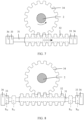
- a straight arrow in FIG. 9 indicates a slide direction of the slide block 32
- a rotation arrow in FIG. 9 indicates a rotation direction of the gear 34.
- the steering wheel 1 rotates counterclockwise relative to the steerable wheel
- the steering wheel needs to rotate clockwise to correct the rotation angle deviation.
- the movable limiting block 33 on the right side of the slide block 32 may be controlled to slide leftward to be in contact with the slide block 32 and push the slide block 32 to slide leftward.
- the gear 34 may rotate clockwise, so that the steering wheel rotates clockwise, to eliminate the rotation angle deviation between the steering wheel 1 and the steerable wheel.
- a straight arrow in FIG. 10 indicates a slide direction of the slide block 32
- a rotation arrow in FIG. 10 indicates a rotation direction of the gear 34.
- the consistency between the rotation angle of the steering wheel and the rotation angle of the steerable wheel means that the correspondence between the rotation angle of the steering wheel and the rotation angle of the steerable wheel is consistent with the pre-stored target correspondence between the rotation angle of the steering wheel and the rotation angle of the steerable wheel.
- the target correspondence may also be referred to as the steering ratio of the vehicle.
- the rotation angle of the steering wheel 1 may be adjusted to be consistent with that of the steerable wheel, to alleviate tire wear generated by adjustment of the steerable wheel, and protect a tire. Dynamic adjustment of the rotation angle of the steering wheel and the rotation angle of the steerable wheel can improve precision of alignment between the steering wheel and the steerable wheel.
- the limiting apparatus 3 of the steer-by-wire system may not only limit steering of the steering wheel 1 and adjust steering of the steering wheel 1 to correct inconsistency between steering of the steerable wheel and steering of the steering wheel 1, but also drive the steering wheel 1 to automatically return.
- the steering controller of the steer-by-wire system may control the movable limiting block 33 to push the slide block 32 to slide on the fixed rod 31, so that the slide block 32 drives the steering column 2 to rotate, and the steering wheel 1 returns.
- a slide speed of the movable limiting block 33 may be controlled to control an automatic return speed of the steering wheel 1.
- the steering wheel 1 when the driver operates the steering wheel 1 to rotate clockwise to a specific position and then takes hands off the steering wheel 1, the steering wheel 1 needs to rotate counterclockwise to return.
- the movable limiting block 33 on the left side of the slide block 32 slides rightward to be in contact with the slide block 32, to push the slide block 32 to slide rightward at a specified speed.
- the gear 34 may rotate counterclockwise.
- both the steering column 2 and the steering wheel 1 rotate counterclockwise, so that the steering wheel 1 rotates counterclockwise.
- the steering controller controls the movable limiting block 33 to stop pushing the slide block 32 to slide rightward, so that the gear 34 stops rotating, and the steering wheel 1 also stays at the return position.
- the steering wheel 1 when the driver operates the steering wheel 1 to rotate counterclockwise to a specific position and then takes hands off the steering wheel 1, the steering wheel 1 needs to rotate clockwise to return.
- the movable limiting block 33 on the right side of the slide block 32 slides leftward to be in contact with the slide block 32, to push the slide block 32 to slide leftward at a specified speed.
- the gear 34 may rotate clockwise.
- both the steering column 2 and the steering wheel 1 rotate clockwise, so that the steering wheel 1 rotates clockwise.
- the steering controller controls the movable limiting block 33 to stop pushing the slide block 32 to slide leftward, so that the gear 34 stops rotating, and the steering wheel 1 also stays at the return position.
- the steer-by-wire system may further include a return driving motor 4, where the return driving motor 4 is configured to drive the steering column 2 to drive the steering wheel 1 to automatically return.
- a corresponding movable limiting block 33 may be controlled based on the foregoing method to push the slide block 32 to slide in a direction that enables the steering wheel 1 to automatically return, so that the steering wheel 1 automatically returns during sliding of the slide block 32.
- the limiting apparatus 3 may further include a damper 37.
- the damper 37 may be installed on the gear 34, and a position of the damper 37 is opposite to a position of the fixed rod 31.
- the damper 37 provides resistance to rotation of the gear 34. This brings the driver with a hand feeling for operation.
- the vehicle in which the steer-by-wire system is located further includes a stability control system.
- a stability control system can start to stabilize the vehicle and prevent an accident such as overturning of the vehicle.
- the steer-by-wire system may use the limiting apparatus 3 to limit rotation of the steering wheel 1, so that the steering wheel 1 no longer rotates without a limitation, but rotates within the target rotation range corresponding to the rotation range of the steerable wheel. Therefore, when the steerable wheel rotates to a limit position, the steering wheel 1 also rotates to a limit position.
- the fixed limiting block 36 may further limit the steering wheel 1 to rotate within the limit rotation range, so that when the steerable wheel rotates within the limit rotation range of the steerable wheel, the steering wheel 1 also rotates within the limit rotation range the steering wheel 1. Therefore, a rotation range of the steering wheel 1 is consistent with a rotation range of the steerable wheel. This facilitates driving safety of the vehicle.
- the movable limiting block 33 may further push the slide block 32 to slide, so that the steering wheel 1 rotates to eliminate the rotation angle deviation between the steering wheel 1 and the steerable wheel, and improve precision of alignment between steering of the steering wheel 1 and steering of the steerable wheel.
- the movable limiting block 33 may further push the slide block 32 to slide, to enable the steering wheel 1 to rotate, so that the steering wheel 1 automatically returns.
- the movable limiting block 33 pushes the slide block 32 to enable the steering wheel 1 to automatically return
- the movable limiting block 33 on the left side pushes the slide block 32 to slide rightward at a specified speed, so that the steering wheel 1 rotates counterclockwise.
- the movable limiting block 33 on the left side stops pushing the slide block 32 to slide rightward. If the steering wheel 1 is enabled to rotate clockwise to the return position, as shown in FIG.
- the movable limiting block 33 on the right side pushes the slide block 32 to slide leftward at a specified speed, so that the steering wheel 1 rotates clockwise.
- the movable limiting block 33 on the right side stops pushing the slide block 32 to slide leftward.
- the steer-by-wire system may use the limiting apparatus to limit rotation of the steering wheel, so that the steering wheel no longer rotates without a limitation, but rotates within the target rotation range corresponding to the rotation range of the steerable wheel. Therefore, when the steerable wheel rotates to a limit position, the steering wheel also rotates to a limit position, so that the rotation of the steering wheel is consistent with rotation of the steerable wheel. This facilitates operation and control of a driver on vehicle steering, and facilitates driving safety.
- An embodiment of this application further provides a vehicle, where the vehicle may be an intelligent car, a new energy car, a self-driving car, or the like.
- the vehicle may include the foregoing steer-by-wire system.
- the steer-by-wire system may use the limiting apparatus to limit rotation of the steering wheel, so that the steering wheel no longer rotates without a limitation, but rotates within a target rotation range corresponding to a rotation range of the steerable wheel.
- a rotation range of the steering wheel is consistent with a rotation range of the steerable wheel. Therefore, when the steerable wheel rotates to a limit position, the steering wheel also rotates to a limit position. This facilitates operation and control of a driver on vehicle steering, and facilitates driving safety.
- An embodiment of this application further provides a steering control method.
- the method may be performed by the foregoing steer-by-wire system, may be specifically performed by the steering controller in the steer-by-wire system, and may be performed based on a procedure shown in FIG. 12 .
- step 111 a rotation range of a steerable wheel of a vehicle in which the steer-by-wire system is located is obtained, and a target rotation range of the steering wheel 1 is calculated based on the rotation range of the steerable wheel.
- the steering controller may first obtain a traveling parameter of the vehicle, for example, a speed of the vehicle and a maximum yaw rate of the vehicle in a working condition. Then the traveling parameter is brought into the foregoing formula 1, to calculate a maximum rotation angle ⁇ f of the steerable wheel in the working condition. Further, a rotation range of the steerable wheel in the working condition is obtained based on the maximum rotation angle ⁇ f of the steerable wheel in the working condition.
- a traveling parameter of the vehicle for example, a speed of the vehicle and a maximum yaw rate of the vehicle in a working condition. Then the traveling parameter is brought into the foregoing formula 1, to calculate a maximum rotation angle ⁇ f of the steerable wheel in the working condition. Further, a rotation range of the steerable wheel in the working condition is obtained based on the maximum rotation angle ⁇ f of the steerable wheel in the working condition.
- a maximum rotation angle of the steering wheel 1 in the working condition is calculated based on a stored steering ratio and the maximum rotation angle ⁇ f of the steerable wheel in the working condition, that is, the maximum rotation angle ⁇ s of the steering wheel in the working condition is calculated according to the foregoing formula 2. Then a target rotation range of the steering wheel in the working condition may be calculated based on the maximum rotation angle ⁇ s of the steering wheel in the working condition.
- a rotation range that is obtained through calculation based on the traveling parameter and that is less than or equal to the limit rotation range of the steerable wheel may be used as the rotation range of the steerable wheel.
- a maximum rotation angle that is obtained through calculation based on the traveling parameter and that is less than or equal to a limit rotation angle of the steerable wheel may be used as the maximum rotation angle of the steerable wheel in the working condition, and then the rotation range of the steerable wheel in the working condition is calculated based on the maximum rotation angle of the steerable wheel in the working condition.
- step 112 a target slide range that is of the movable limiting block 33 and that corresponds to the target rotation range of the steering wheel 1 is obtained based on a correspondence between a rotation range of the steering wheel 1 and a slide range of the movable limiting block 33.
- the correspondence between a rotation range of the steering wheel 1 and a slide range of the movable limiting block 33 is pre-stored in the steer-by-wire system.
- the steering controller may find the target slide range that is of the movable limiting block 33 and that corresponds to the target rotation range of the steering wheel 1.
- step 113 the movable limiting block 33 is controlled to slide within the target slide range, to limit the slide block 32 to slide on the fixed rod 31, so that the steering wheel 1 rotates within the target rotation range.
- the steering controller may control the slide driving motor 35 of the movable limiting block 33 to drive the movable limiting block 33 to move to a target position.
- a distance between a default position and the target position of the movable limiting block 33 is the target slide range of the movable limiting block 33
- the default position of the movable limiting block 33 is a position at which the movable limiting block 33 is in contact with the fixed limiting block 36.
- Two movable limiting blocks 33 slide within the target slide range, which limits the slide block 32 to slide within a specific range, thereby limiting the steering wheel 1 to rotate within the target rotation range.
- the steering controller controls the movable limiting block 33 on a left side to move rightward from a default position S 10 to a first target position Sn, and controls the movable limiting block 33 on a right side to move leftward from a default position S 20 to a second target position S 12 .
- a range between the default position S 10 of the movable limiting block on the left side and the first target position S 11 is a target slide range of the movable limiting block 33 on the left side
- a range between the default position S 20 of the movable limiting block on the right side and the second target position S 12 is a target slide range of the movable limiting block 33 on the right side.
- a slide range between the first target position S 11 and the second target position S 12 is a slide range of the slide block 32.
- the steering wheel 1 rotates within the target rotation range.
- the movable limiting block on the left side is located in the first target position S 11 to limit clockwise rotation of the steering wheel.
- the movable limiting block on the right side is located in the second target position S 12 to limit counterclockwise rotation of the steering wheel.
- the steer-by-wire system may use the limiting apparatus to limit rotation of the steering wheel, so that the steering wheel no longer rotates without a limitation, but rotates within the target rotation range corresponding to the rotation range of the steerable wheel. Therefore, when the steerable wheel rotates to a limit position, the steering wheel also rotates to a limit position, so that the rotation of the steering wheel is consistent with rotation of the steerable wheel. This facilitates operation and control of a driver on vehicle steering, and facilitates driving safety.
- the method may be further used to adjust a rotation angle of the steering wheel, so that the rotation angle of the steering wheel is always consistent with a rotation angle of the steerable wheel.
- the steering controller may obtain a current rotation angle of the steering wheel 1, a current rotation angle of the steerable wheel, and a stored target correspondence between the rotation angle of the steering wheel 1 and the rotation angle of the steerable wheel. Then, when detecting that a correspondence between the current rotation angle of the steering wheel 1 and the current rotation angle of the steerable wheel does not meet the target correspondence, the steering controller determines that steering of the steering wheel 1 is inconsistent with steering of the steerable wheel.
- the steering controller controls, based on a rotation angle deviation between the current rotation angle of the steering wheel 1 and the current rotation angle of the steerable wheel, the movable limiting block 33 to push the slide block 32 to slide on the fixed rod 31.
- the steering controller controls the movable limiting block 33 to stop pushing the slide block 32 to slide on the fixed rod 31.
- the movable limiting block 33 may further push the slide block 32 to slide, so that the steering wheel 1 rotates to eliminate a deviation between steering of the steering wheel 1 and steering of the steerable wheel, and improve precision of alignment between steering of the steering wheel 1 and steering of the steerable wheel.
- the method may be further used to control automatic return of the steering wheel.
- the steering controller may control the movable limiting block 33 to push the slide block 32 to slide on the fixed rod 31.
- the steering controller controls the movable limiting block 33 to stop pushing the slide block 32 to slide on the fixed rod 31.
- the return driving motor 4 of the steer-by-wire system drives the steering column 2 to rotate, so that the steering wheel automatically returns.
- the steering controller may control the movable limiting block 33 to push the slide block 32 to slide on the fixed rod 31 at a specified speed.
- the steering controller controls the movable limiting block 33 to stop pushing the slide block 32 to slide on the fixed rod 31.
- the limiting apparatus 3 can drive the steering wheel 1 to automatically return, thereby ensuring an automatic return function of the steering wheel 1.
- the limiting apparatus may not only limit rotation of the steering wheel, but also adjust the rotation angle of the steering wheel, so that steering of the steering wheel is always consistent with steering of the steerable wheel, to improve precision of alignment between the steering wheel and the steerable wheel, and drive the steering wheel to automatically return.
- a scenario is a process in which the limiting apparatus is used to align the rotation angle of the steering wheel and the rotation angle of the steerable wheel.
- a scenario is a scenario in which the limiting apparatus limits the rotation of the steering wheel.
- Another scenario is a scenario in which the driving motor fails, for example, a process in which the slide driving motor fails or the return driving motor fails.
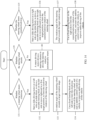
- the steer-by-wire system may periodically perform the alignment process, which may be performed based on a procedure shown in FIG. 13 .
- a current rotation angle of the steering wheel and a current rotation angle of the steerable wheel are respectively obtained by using a rotation angle sensor of the steering wheel and a rotation angle sensor of the steerable wheel, and whether the rotation angle of the steering wheel is consistent with the rotation angle of the steerable wheel is further determined based on a pre-stored correspondence between the rotation angle of the steering wheel and the rotation angle of the steerable wheel. If the rotation angle of the steering wheel is consistent with the rotation angle of the steerable wheel, step 126 is proceeded and the alignment ends. If the rotation angle of the steering wheel is inconsistent with the rotation angle of the steerable wheel, step 122 is proceeded to determine whether the steering wheel deflects counterclockwise relative to the steerable wheel.
- step 124 is proceeded. If the steering wheel does not deflect counterclockwise relative to the steerable wheel, step 123 is proceeded, and then step 125 is proceeded. After step 124 and step 125 are performed, step 126 is proceeded, and then the alignment ends.
- step 124 the slide driving motor on the right side of the slide block is started to drive the movable limiting block on the right side to push the slide block to slide leftward, so that the steering column drives the steering wheel to rotate clockwise, to correct a deviation between the steering wheel and the steerable wheel.
- step 125 the slide driving motor on the left side of the slide block is started to drive the movable limiting block on the left side to push the slide block to slide rightward, so that the steering column drives the steering wheel to rotate counterclockwise, to correct a deviation between the steering wheel and the steerable wheel.
- the steer-by-wire system may calculate a target rotation range of the steering wheel in a working condition based on the current working condition, and after determining the target rotation range, control, based on a procedure shown in FIG. 14 , the steering wheel to rotate within the target rotation range.
- step 131 it is determined whether the steering wheel steers clockwise. If the steering wheel steers clockwise, step 132 is proceeded; or if the steering wheel does not steer clockwise, step 135 is proceeded, or step 139 is proceeded.
- step 132 the slide driving motor on the left side of the slide block is started to drive the movable limiting block on the left side to move rightward to a first target position, to limit clockwise rotation of the steering wheel. Then, step 133 is proceeded. A driver operates the steering wheel with excessive strength, so that the rotation of the steering wheel exceeds the target rotation range. In this case, step 134 is proceeded.
- the fixed limiting block on the left side is used to limit the clockwise rotation of the steering wheel, and a stability control system of the vehicle is started to ensure stable driving of the vehicle.
- step 136 may be proceeded.
- the slide driving motor on the right side of the slide block is started to drive the movable limiting block on the right side to move leftward to a second target position, to limit counterclockwise rotation of the steering wheel.
- step 137 is proceeded.
- a driver operates the steering wheel with excessive strength, so that the rotation of the steering wheel exceeds the target rotation range.
- step 138 is proceeded.
- the fixed limiting block on the right side is used to limit the counterclockwise rotation of the steering wheel, and the stability control system of the vehicle is started to ensure stable driving of the vehicle.
- step 139 may be proceeded to step 140.
- the return driving motor is controlled to drive the steering column to drive the steering wheel to automatically return.
- the steer-by-wire system may detect, in real time, whether the slide driving motor and the return driving motor fail. As shown in FIG. 15 , whether the slide driving motor fails is determined in step 141. If the slide driving motor fails, step 142 is proceeded. The fixed limiting blocks located on both sides of the slide block are used to limit sliding of the slide block, to limit rotation of the steering wheel. Whether the return driving motor fails is determined in step 143. If the return driving motor fails, step 144 is proceeded. A corresponding movable limiting block is determined, based on a rotation direction required for return of the steering wheel, to push the slide block to slide on the fixed rod, so that the steering column drives the steering wheel to automatically return.
- the steer-by-wire system may use the limiting apparatus to limit the rotation of the steering wheel, so that the steering wheel no longer rotates without a limitation, but rotates within the target rotation range corresponding to the rotation range of the steerable wheel.
- the rotation range of the steering wheel is consistent with the rotation range of the steerable wheel. Therefore, when the steerable wheel rotates to a limit position, the steering wheel also rotates to a limit position. This facilitates operation and control of a driver on vehicle steering, and facilitates driving safety.
- the controller may be a controller of a vehicle, for example, may be a steering controller of the vehicle, and may be configured to perform the foregoing steering control method.
- the method may be used to enable a limiting apparatus to limit rotation of a steering wheel, so that the steering wheel no longer rotates without a limitation, but rotates within a target rotation range corresponding to a rotation range of a steerable wheel. In this way, the rotation range of the steering wheel is consistent with the rotation range of the steerable wheel. Therefore, when the steerable wheel rotates to a limit position, the steering wheel also rotates to a limit position. This facilitates operation and control of a driver on vehicle steering, and facilitates driving safety.
Landscapes
- Engineering & Computer Science (AREA)
- Chemical & Material Sciences (AREA)
- Combustion & Propulsion (AREA)
- Transportation (AREA)
- Mechanical Engineering (AREA)
- Steering Control In Accordance With Driving Conditions (AREA)
- Power Steering Mechanism (AREA)
Abstract
Description
- This application relates to the field of vehicle steering technologies, and in particular, to a steer-by-wire system and a steering control method.
- A steer-by-wire system is a system for controlling vehicle steering by using an electrical signal, and a mechanical connection apparatus between a steering wheel and a steerable wheel is canceled.
- The steer-by-wire system mainly includes a steering controller, a steering driving motor, a steering wheel, a steering column, and the like. An output shaft of the steering driving motor is connected to the steerable wheel through rotation. The steering wheel is installed at an end of the steering column. The steering column has a sensor for collecting a rotation angle and torque of the steering wheel. In this way, when a driver operates the steering wheel, the steering controller may obtain the rotation angle and torque of the steering wheel by using the sensor, and then may control, based on the rotation angle and torque of the steering wheel, the steering driving motor to drive the steerable wheel to steer.
- Because the steerable wheel has a rotation range, when rotating to a limit position, the steerable wheel cannot continue to rotate, but the steering wheel can rotate without a limitation. In this way, a rotation range of the steering wheel may be inconsistent with the rotation range of the steerable wheel, which affects operation and control of the driver on vehicle steering.
- This application provides a steer-by-wire system and a steering control method, to overcome a problem in the conventional technology that a steerable wheel has a rotation range limitation but a steering wheel does not have a rotation range limitation. Technical solutions are as follows.
- According to an aspect, a steer-by-wire system is provided, where the steer-by-wire system includes a steering column and a limiting apparatus. The limiting apparatus includes a fixed rod, a slide block, and a movable limiting block. The slide block is located on the fixed rod, and the slide block can slide on the fixed rod as the steering column rotates. The movable limiting block is located on the fixed rod, and can slide on the fixed rod, to limit the slide block to slide on the fixed rod. Therefore, the steering column rotates within a target rotation range.
- In an example, the steer-by-wire system may further include a steering wheel. The steering wheel is fixed at an end of the steering column. The steering column may synchronously rotate with the steering wheel. For example, when the steering wheel rotates, the steering column can be driven to synchronously rotate; and when the steering column rotates, the steering wheel can also be driven to synchronously rotate, so that a rotation angle of the steering column may be used to represent a rotation angle of the steering wheel, and torque of the steering column may also be used to represent torque of the steering wheel. Therefore, in this specification, the rotation angle of the steering column may be equivalent to the rotation angle of the steering wheel, and a rotation range of the steering column may be equivalent to a rotation range of the steering wheel.
- To obtain the rotation angle and the torque of the steering wheel, a rotation angle sensor and a torque sensor may be installed on the steering column. Correspondingly, the torque sensor and the rotation angle sensor are installed on the steering column. The torque sensor can collect torque generated during rotation of the steering column. The rotation angle sensor can collect a rotation angle generated during rotation of the steering column. The torque and the rotation angle of the steering column may be respectively used as the torque and the rotation angle of the steering wheel.
- In an example, a steering driving motor of the steer-by-wire system is connected to a steerable wheel of a vehicle. The steerable wheel may be a left front wheel and a right front wheel of the vehicle. In this way, after obtaining the torque and the rotation angle of the steering wheel by using the torque sensor and the rotation angle sensor, a steering controller of the steer-by-wire system may control a steering driving apparatus to drive the steerable wheel to steer, to implement wire control steering of the vehicle.
- Rotation of the steerable wheel is limited, and the steerable wheel cannot rotate without a limitation. Therefore, to adapt to the rotation of the steerable wheel, rotation of the steering wheel also needs to be limited. Correspondingly, the steer-by-wire system further includes the limiting apparatus. The limiting apparatus may limit the rotation of the steering wheel through sliding of the slide block and the movable limiting block on the fixed rod and a rotation connection between the slide block and the steering column, so that the steering wheel rotates within a target rotation range. The target rotation range is obtained through calculation based on a traveling parameter of a vehicle in which the steer-by-wire system is located.
- It can be learned that the steer-by-wire system may use the limiting apparatus to limit the rotation of the steering wheel, so that the steering wheel no longer rotates without a limitation, but rotates within the target rotation range corresponding to the rotation range of the steerable wheel. In this way, the rotation range of the steering wheel is consistent with the rotation range of the steerable wheel. Therefore, when the steerable wheel rotates to a limit position, the steering wheel also rotates to a limit position. This facilitates operation and control of a driver on vehicle steering, and facilitates driving safety.
- In a possible implementation, the limiting apparatus further includes a gear. The gear is sleeved on the steering column and synchronously rotates with the steering column. The slide block has a rack that engages with the gear. The slide block engages with the gear. When the gear rotates with the steering column, the gear pushes the slide block to slide on the fixed rod.
- In an example, the slide block is sleeved on the fixed rod, an outer wall of the slide block engages with the gear, and the gear is sleeved on the steering column and can move synchronously with the steering column. In this way, when the steering column rotates, the gear sleeved on the steering column also rotates with the steering column. Because the gear engages with the slide block, the slide block can be pushed to slide on the fixed rod when the gear rotates. In addition, when the slide block slides on the fixed rod, the gear may be pushed to rotate. The gear and the steering column synchronously rotate, thereby implementing a rotation connection between the slide block and the steering column.
- It can be learned that the rotation connection between the slide block and the steering column means that rotation of the steering column can be driven when the slide block slides and moves on the fixed rod, and that rotation of the steering column can also drive the slide block to slide and move on the fixed rod.
- In addition, because there is a rotation connection between the slide block and the steering column, a slide range of the slide block on the fixed rod may be limited to limit a rotation range of the steering column. The rotation range of the steering column may be used to represent the rotation range of the steering wheel, so that sliding of the slide block may be limited, to limit the rotation range of the steering wheel.
- When sliding to be in contact with the slide block, the movable limiting block can be locked on the fixed rod, to limit sliding of the slide block, so that the slide block cannot continue to slide in a direction toward the movable limiting block. It can be learned that the movable limiting block can limit the slide range of the slide block. Once the slide range of the slide block is limited, the rotation range of the steering column is limited. The steering column synchronously rotates with the steering wheel, so that the rotation range of the steering wheel is also limited.
- It can be learned that the movable limiting block of the limiting apparatus may limit the slide range of the slide block to further limit the rotation range of the steering wheel, so that the steering wheel rotates within the target rotation range.
- In a possible implementation, the fixed rod is a screw, and both the slide block and the movable limiting block are ball nuts. Both the slide block and the movable limiting block are sleeved on the fixed rod. The slide block and the movable limiting block can spirally slide on the fixed rod.
- Both the slide block and the movable limiting block are ball nuts, and the fixed rod is a screw. In this way, the slide block spirally slides on the screw, and the movable limiting block spirally slides on the screw. In addition, a ball is in a spiral groove of the slide block, and a ball is in a spiral groove of the movable limiting block, to reduce wear between the slide block and the fixed rod, reduce wear between the movable limiting block and the fixed rod, and prolong a service life of the limiting apparatus.
- In a possible implementation, the steer-by-wire system further includes a slide driving motor. The slide driving motor drives the movable limiting block to slide on the fixed rod.
- In an example, the steer-by-wire system may include one slide driving motor. The slide driving motor is configured to drive the foregoing plurality of movable limiting blocks to slide on the fixed rod. Alternatively, a quantity of slide driving motors may be the same as a quantity of movable limiting blocks. Each movable limiting block is driven by using one slide driving motor. This embodiment sets no limitation on the quantity of slide driving motors included in the steer-by-wire system. A skilled person may flexibly select the quantity based on an actual situation.
- In an example, when the movable limiting block limits the slide block, if the slide driving motor drives the movable limiting block to be in contact with the slide block, the slide driving motor still continues to drive the movable limiting block to maintain contact between the movable limiting block and the slide block, to apply thrust to the slide block, so as to prevent the slide block from continuing to slide.
- In a possible implementation, the movable limiting block is further configured to: when the rotation angle of the steering wheel is inconsistent with a rotation angle of the steerable wheel, push the slide block to slide on the fixed rod, so that the slide block drives the steering column to rotate, to correct a rotation angle deviation between the steering wheel and the steerable wheel.
- Because the rotation angle of the steering column may be equal to the rotation angle of the steering wheel, consistency between the rotation angle of the steering wheel and the rotation angle of the steerable wheel may also be referred to as consistency between the rotation angle of the steering column and the rotation angle of the steerable wheel, and inconsistency between the rotation angle of the steering wheel and the rotation angle of the steerable wheel may also be referred to as inconsistency between the rotation angle of the steering column and the rotation angle of the steerable wheel.
- The consistency between the rotation angle of the steering wheel and the rotation angle of the steerable wheel means that a correspondence between the rotation angle of the steering wheel and the rotation angle of the steerable wheel meets a pre-stored target correspondence between the rotation angle of the steering wheel and the rotation angle of the steerable wheel. The inconsistency means that the correspondence between the rotation angle of the steering wheel and the rotation angle of the steerable wheel does not meet the target correspondence.
- In an example, the steering controller of the steer-by-wire system obtains a current rotation angle of the steering wheel by using the rotation angle sensor, obtains a current rotation angle of the steerable wheel by using a rotation angle sensor installed on the steerable wheel, and detects whether a correspondence between the current rotation angle of the steering wheel and the current rotation angle of the steerable wheel is consistent with the pre-stored target correspondence. If the correspondence between the current rotation angle of the steering wheel and the current rotation angle of the steerable wheel is inconsistent with the pre-stored target correspondence, the steering controller may calculate a rotation angle deviation between the current rotation angle of the steering wheel and the current rotation angle of the steerable wheel; and then control, based on the rotation angle deviation, a corresponding movable limiting block to push the slide block to slide on the fixed rod in a direction used to eliminate the rotation angle deviation. Because there is a rotation connection between the slide block and the steering column, the steering column can rotate, to eliminate the rotation angle deviation between the steering wheel and the steerable wheel.
- It can be learned that the rotation angle of the steering wheel may be adjusted to be consistent with that of the steerable wheel, to alleviate tire wear generated by adjustment of the steerable wheel, and protect a tire. Dynamic adjustment of the rotation angle of the steering wheel and the rotation angle of the steerable wheel can improve precision of alignment between the steering wheel and the steerable wheel.
- In a possible implementation, the movable limiting block is further configured to: when it is detected that the steering wheel intends to return and a return driving motor of the steer-by-wire system fails, push the slide block to slide on the fixed rod, so that the slide block drives the steering column to rotate, and the steering wheel returns.
- In a process in which the steering wheel returns, a slide speed of the movable limiting block may be controlled to control an automatic return speed of the steering wheel.
- In an example, when a wire control steering detects that the steering wheel intends to return and the return driving motor fails and cannot drive the steering column to drive the steering wheel to automatically return, a corresponding movable limiting block may be controlled to push the slide block to slide in a direction that enables the steering wheel to automatically return, so that the steering wheel automatically returns during sliding of the slide block. It can be learned that even if the return driving motor that drives the steering wheel to automatically return fails, automatic return of the steering wheel can be implemented.
- In a possible implementation, the target rotation range is specifically obtained through calculation based on the rotation range of the steerable wheel and a stored steering ratio. The steering ratio is a ratio of the rotation angle of the steering wheel to the rotation angle of the steerable wheel. The rotation range of the steerable wheel is a rotation range that is obtained through calculation based on a traveling parameter of the vehicle in a working condition and that is less than or equal to a limit rotation range of the steerable wheel. The traveling parameter includes a speed of the vehicle and a maximum yaw rate of the vehicle in the working condition. The limit rotation range of the steerable wheel is an attribute value of the vehicle.
- In an example, a maximum rotation angle of the steerable wheel in the working condition may be calculated based on the traveling parameter of the vehicle in the working condition, and the maximum rotation angle is less than or equal to a limit rotation angle of the steerable wheel. The rotation range of the steerable wheel is obtained based on a rotation direction of the steerable wheel. Then, a maximum rotation angle of the steering wheel may be calculated based on the pre-stored steering ratio and the maximum rotation angle that is of the steerable wheel and that is less than or equal to the limit rotation angle. Afterwards, the target rotation range of the steering wheel is obtained based on a rotation direction of the steering wheel.
- The rotation range of the steerable wheel obtained based on the limit rotation angle and the rotation direction of the steerable wheel is the limit rotation range of the steerable wheel. In this case, the rotation angle that is of the steering wheel and that is obtained based on the limit rotation angle of the steerable wheel and the steering ratio is referred to as a limit rotation angle of the steering wheel, and the target rotation range that is of the steering wheel and that is obtained based on the limit rotation angle and the rotation direction of the steering wheel is a limit rotation range of the steering wheel.
- In a possible implementation, the steer-by-wire system further includes a fixed limiting block. The fixed limiting block is fixed at an end of the fixed rod, and is configured to limit the movable limiting block to slide on the fixed rod, to limit the steering wheel to rotate within the limit rotation range. The limit rotation range of the steering wheel is a maximum target rotation range of the steering wheel, and is obtained through calculation based on the limit rotation range of the steerable wheel.
- When the movable limiting block limits the steering wheel, because the movable limiting block can also slide on the fixed rod, if the driver operates the steering wheel with excessive strength, the slide block may push the movable limiting block to slide on the fixed rod. As a result, the movable limiting block cannot limit sliding of the slide block.
- To avoid occurrence of the foregoing situation and enable the steering wheel to have the limit rotation range, correspondingly, the steer-by-wire system further includes the fixed limiting block. The fixed limiting block is fixed at the end of the fixed rod, and is configured to limit the movable limiting block to slide on the fixed rod, to limit the steering wheel to rotate within the limit rotation range.
- When the target rotation range of the steering wheel is the limit rotation range of the steering wheel, if the steering wheel rotates clockwise to the maximum rotation angle, the movable limiting block on a left side is in contact with the fixed limiting block on the left side; and if the steering wheel rotates counterclockwise to the maximum rotation angle, the movable limiting block on a right side is in contact with the fixed limiting block on the right side. A distance between the two movable limiting blocks is a limit slide range of the slide block on the fixed rod.
- According to another aspect, this application further provides a steering control method, where the method is applied to the foregoing steer-by-wire system, and the method includes:
- obtaining a target rotation range of a steering column;
- obtaining, based on a correspondence between a rotation range of the steering column and a slide range of a movable limiting block, a target slide range that is of the movable limiting block and that corresponds to the target rotation range of the steering column; and
- controlling the movable limiting block to slide within the target slide range, to limit a slide block to slide on a fixed rod, so that the steering column rotates within the target rotation range.
- In an example, the steering controller may first obtain a traveling parameter of a vehicle in which the steering controller is located, calculate a rotation range of a steerable wheel in a working condition based on the traveling parameter, and then calculate a target rotation range of the steering wheel. A correspondence between a rotation range of the steering wheel and the slide range of the movable limiting block is pre-stored in the steer-by-wire system. After calculating the target rotation range of the steering wheel, the steering controller may find a target slide range that is of the movable limiting block and that corresponds to the target rotation range of the steering wheel.
- After finding the target slide range of the movable limiting block, the steering controller may control the slide driving motor of the movable limiting block to drive the movable limiting block to move to a target position. A distance between a default position and the target position of the movable limiting block is the target slide range of the movable limiting block, and the default position of the movable limiting block is a position at which the movable limiting block is in contact with the fixed limiting block. Two movable limiting blocks slide within the target slide range. This limits the slide block to slide within a specific range, thereby limiting the steering wheel to rotate within the target rotation range.
- It can be learned that the steer-by-wire system may use the limiting apparatus to limit rotation of the steering wheel, so that the steering wheel no longer rotates without a limitation, but rotates within the target rotation range corresponding to the rotation range of the steerable wheel. Therefore, when the steerable wheel rotates to a limit position, the steering wheel also rotates to a limit position, so that the rotation of the steering wheel is consistent with rotation of the steerable wheel. This facilitates operation and control of a driver on vehicle steering, and facilitates driving safety.
- In a possible implementation, the obtaining a target rotation range of the steering column includes:
- obtaining a traveling parameter of a vehicle in which the steer-by-wire system is located and a limit rotation range of the steerable wheel of the vehicle;
- using, as the rotation range of the steerable wheel, a rotation range that is obtained through calculation based on the traveling parameter and that is less than or equal to the limit rotation range of the steerable wheel; and
- calculating the target rotation range of the steering column based on the rotation range of the steerable wheel and a stored steering ratio.
- The traveling parameter includes a speed of the vehicle and a maximum yaw rate of the vehicle in a working condition. The limit rotation range of the steerable wheel is an attribute value of the vehicle. The steering ratio is a ratio of a rotation angle of the steering wheel to a rotation angle of the steerable wheel.
- Because the steerable wheel has a limit rotation range, correspondingly, a rotation range that is obtained through calculation based on the traveling parameter and that is less than or equal to the limit rotation range of the steerable wheel may be used as the rotation range of the steerable wheel. Then, the target rotation range of the steering wheel is calculated based on the rotation range of the steerable wheel and the pre-stored steering ratio. The steering ratio is a ratio of the rotation angle of the steering wheel to the rotation angle of the steerable wheel, namely, a correspondence between the rotation angle of the steering wheel and the rotation angle of the steerable wheel.
- In a possible implementation, the method further includes:
- obtaining a current rotation angle of the steering wheel, a current rotation angle of the steerable wheel, and a stored target correspondence between the rotation angle of the steering wheel and the rotation angle of the steerable wheel;
- when it is detected that a correspondence between the current rotation angle of the steering wheel and the current rotation angle of the steerable wheel does not meet the target correspondence, determining that the rotation angle of the steering wheel is inconsistent with the rotation angle of the steerable wheel; and
- controlling, based on a rotation angle deviation between the current rotation angle of the steering wheel and the current rotation angle of the steerable wheel, the movable limiting block to push the slide block to slide on the fixed rod; and
- when it is detected that the correspondence between the current rotation angle of the steering wheel and the current rotation angle of the steerable wheel meets the target correspondence, determining that the rotation angle of the steering wheel is consistent with the rotation angle of the steerable wheel, and controlling the movable limiting block to stop pushing the slide block to slide on the fixed rod.
- It can be learned that in a process in which the steering wheel and the steerable wheel rotate, when there is misalignment between steering of the steering wheel and steering of the steerable wheel, that is, the pre-stored correspondence is not met, the movable limiting block may further push the slide block to slide, so that the steering wheel rotates to eliminate a deviation between steering of the steering wheel and steering of the steerable wheel, and improve precision of alignment between steering of the steering wheel and steering of the steerable wheel.
- In a possible implementation, the method further includes:
- when it is detected that the steering wheel intends to return and a return driving motor of the steer-by-wire system fails, controlling the movable limiting block to push the slide block to slide on the fixed rod; and
- when it is detected that the steering wheel returns, controlling the movable limiting block to stop pushing the slide block to slide on the fixed rod.
- It can be learned that, even if the return driving motor that drives the steering wheel to automatically return fails due to a fault, the limiting apparatus can drive the steering wheel to automatically return, thereby ensuring an automatic return function of the steering wheel.
- According to another aspect, a vehicle is further provided, and the vehicle may include the foregoing steer-by-wire system.
- According to another aspect, a controller is further provided, and the controller may be configured to perform the foregoing steering control method.
- In embodiments of this application, the steer-by-wire system may use the limiting apparatus to limit the rotation of the steering wheel, so that the steering wheel no longer rotates without a limitation, but rotates within the target rotation range corresponding to the rotation range of the steerable wheel. In this way, the rotation range of the steering wheel is consistent with the rotation range of the steerable wheel. Therefore, when the steerable wheel rotates to a limit position, the steering wheel also rotates to a limit position. This facilitates operation and control of a driver on vehicle steering, and facilitates driving safety.
-
-
FIG. 1 is a schematic diagram of a structure of a steer-by-wire system according to an embodiment of this application; -
FIG. 2 is a schematic diagram of a structure of a steer-by-wire system according to an embodiment of this application; -
FIG. 3 is a schematic diagram of a structure of a rotation connection between a gear of a limiting apparatus and a slide block according to an embodiment of this application; -
FIG. 4 is a schematic diagram of a structure of a steer-by-wire system according to an embodiment of this application; -
FIG. 5 is a schematic diagram of a structure of a steer-by-wire system according to an embodiment of this application; -
FIG. 6 is a schematic diagram of a structure in which a movable limiting block and a fixed limiting block that are on a left side limit clockwise rotation of a gear according to an embodiment of this application; -
FIG. 7 is a schematic diagram of a structure in which a movable limiting block and a fixed limiting block that are on a right side limit counterclockwise rotation of a gear according to an embodiment of this application; -
FIG. 8 is a schematic diagram of a structure in which a fixed limiting block and a movable limiting block limit sliding of a slide block according to an embodiment of this application; -
FIG. 9 is a schematic diagram of a structure in which a movable limiting block pushes a slide block to slide rightward to cause counterclockwise rotation of a gear according to an embodiment of this application; -
FIG. 10 is a schematic diagram of a structure in which a movable limiting block pushes a slide block to slide leftward to cause clockwise rotation of a gear according to an embodiment of this application; -
FIG. 11 is a schematic diagram of a structure of a steer-by-wire system according to an embodiment of this application; -
FIG. 12 is a schematic diagram of a steering control procedure according to an embodiment of this application; -
FIG. 13 is a schematic diagram of a procedure for correcting a rotation angle deviation between a steering wheel and a steerable wheel according to an embodiment of this application; -
FIG. 14 is a schematic diagram of a procedure for limiting clockwise rotation and counterclockwise rotation of a steering wheel according to an embodiment of this application; and -
FIG. 15 is a schematic diagram of a procedure in which a steering wheel returns and a steering wheel is limited when a driving motor fails according to an embodiment of this application. - 1. steering wheel; 2. steering column; 3. limiting apparatus; 4. return driving motor; 21. torque sensor; 22. rotation angle sensor; 31. fixed rod; 32. slide block; 33. movable limiting block; 34. gear; 35. slide driving motor; 36. fixed limiting block; 37. damper; 33A. first movable limiting block; 33B. second movable limiting block; 35A. first slide driving motor; and 35B. second slide driving motor.
- Embodiments of this application provide a steer-by-wire system. The steer-by-wire system may be applied to an intelligent car, a new energy car, or a self-driving car. These cars may be collectively referred to as vehicles. The steer-by-wire system is a system for controlling vehicle steering by using an electrical signal, and a mechanical connection apparatus between a steering wheel and a steerable wheel is canceled, so that rotation of the steering wheel and rotation of the steerable wheel are independent of each other. The embodiments provide a steer-by-wire system, which can control a rotation range of the steering wheel, can maintain consistence between steering of the steering wheel and steering of the steerable wheel, can control automatic return of the steering wheel, and so on.
- As shown in
FIG. 1 , the steer-by-wire system includes asteering wheel 1, asteering column 2, and a limitingapparatus 3. The limitingapparatus 3 includes a fixedrod 31, aslide block 32, and a movable limitingblock 33. Thesteering wheel 1 is located at an end of thesteering column 2. Theslide block 32 is located on the fixedrod 31, and theslide block 32 can slide on the fixedrod 31. Theslide block 32 is connected to thesteering column 2 through rotation, so that when thesteering column 2 rotates with thesteering wheel 1, theslide block 32 can slide on the fixedrod 31 with rotation of thesteering column 2. The movable limitingblock 33 is located on the fixedrod 31, and the movable limitingblock 33 can slide on the fixedrod 31, to limit theslide block 32 to slide on the fixedrod 31, so that thesteering wheel 1 rotates within a target rotation range. The target rotation range is obtained through calculation based on a traveling parameter of a vehicle in which the steer-by-wire system is located. - The limiting
apparatus 3 may be configured to limit thesteering wheel 1, so that thesteering wheel 1 may change from "rotating without a limitation" to "having a rotation range", to limit steering of thesteering wheel 1. The limitingapparatus 3 may be further configured to correct a rotation angle of thesteering wheel 1 when there is a rotation angle deviation between thesteering wheel 1 and a steerable wheel, so that steering of thesteering wheel 1 is consistent and aligned with steering of the steerable wheel. The limitingapparatus 3 may be further configured to enable thesteering wheel 1 to automatically return. For a specific implementation structure and process, refer to the following description. - In an example, as shown in
FIG. 1 , thesteering wheel 1 is fixed at the end of thesteering column 2, and thesteering column 2 can rotate synchronously with thesteering wheel 1. For example, when thesteering wheel 1 rotates, thesteering column 2 can be driven to synchronously rotate; and when thesteering column 2 rotates, thesteering wheel 1 can also be driven to synchronously rotate, so that a rotation angle of thesteering column 2 may be used to represent the rotation angle of thesteering wheel 1, and torque of thesteering column 2 may also be used to represent torque of thesteering wheel 1. Therefore, in this specification, the rotation angle of the steering column may be equivalent to the rotation angle of the steering wheel, and a rotation range of the steering column may be equivalent to a rotation range of the steering wheel. - Correspondingly, to obtain the rotation angle and torque of the
steering wheel 1, a rotation angle sensor and a torque sensor may be installed on thesteering column 2. Correspondingly, as shown inFIG. 1 , atorque sensor 21 and arotation angle sensor 22 are installed on thesteering column 2. Thetorque sensor 21 can collect torque generated during rotation of thesteering column 2. Therotation angle sensor 22 can collect a rotation angle generated during rotation of thesteering column 2. The torque and the rotation angle of thesteering column 2 may be respectively used as the torque and the rotation angle of thesteering wheel 1. Both thetorque sensor 21 and therotation angle sensor 22 may send collected data to a steering controller of the steer-by-wire system, so that the steering controller obtains operation performed by a driver on thesteering wheel 1, and controls steering and straight-moving of a vehicle based on the operation performed by the driver. - The steering controller of the steer-by-wire system may be a controller in the steer-by-wire system, and is configured to control vehicle steering; or may be an entire vehicle controller of a vehicle in which the steer-by-wire system is located. This is not limited in this embodiment.
- In an example, a steering driving motor of the steer-by-wire system is connected to a steerable wheel of the vehicle. The steerable wheel may be a left front wheel and a right front wheel of the vehicle. In this way, after obtaining the torque and the rotation angle of the
steering wheel 1 by using thetorque sensor 21 and therotation angle sensor 22, the steering controller of the steer-by-wire system may control a steering driving apparatus to drive the steerable wheel to steer, to implement wire control steering of the vehicle. - Rotation of the steerable wheel is limited, and the steerable wheel cannot rotate without a limitation. Therefore, to adapt to the rotation of the steerable wheel, rotation of the
steering wheel 1 also needs to be limited. Correspondingly, as shown inFIG. 1 , the steer-by-wire system further includes the limitingapparatus 3. The limitingapparatus 3 may limit the rotation of thesteering wheel 1 through sliding of theslide block 32 and the movable limitingblock 33 on the fixedrod 31 and a rotation connection between theslide block 32 and thesteering column 2, so that thesteering wheel 1 rotates within a target rotation range. The target rotation range is obtained through calculation based on a traveling parameter of a vehicle in which the steer-by-wire system is located. - First, a specific implementation structure of the limiting apparatus is described, and then a process of calculating the target rotation range of the
steering wheel 1 is described. - For ease of description of this embodiment, azimuth or position relationships indicated by "left", "right", "clockwise", "counterclockwise", and the like are introduced, which are all based on azimuth or position relationships shown in the accompanying drawings. This is merely for ease of description of this solution, and is not specifically limited. In addition, "first", "second", and the like in this specification are only used for description, and cannot be understood as an indication or implication of relative importance.
- As shown in
FIG. 1 , theslide block 32 is located on the fixedrod 31, and can slide leftward and rightward on the fixedrod 31. An installation manner of theslide block 32 and the fixedrod 31 may be as follows: Theslide block 32 may have a tubular structure and be sleeved on the fixedrod 31, so that theslide block 32 can slide leftward and rightward along the fixedrod 31. To reduce friction between theslide block 32 and the fixedrod 31, theslide block 32 may be a ball nut, and the fixedrod 31 may be a screw having a thread, so that theslide block 32 can spirally slide leftward and rightward on the fixedrod 31. In addition, a ball is in a spiral groove of theslide block 32, to reduce wear between theslide block 32 and the fixedrod 31, and prolong a service life of the limitingapparatus 3. - To implement that the
steering column 2 can rotate when theslide block 32 slides on the fixedrod 31, and that theslide block 32 can slide on the fixedrod 31 when thesteering column 2 rotates, correspondingly, there may be a rotation connection between theslide block 32 and thesteering column 2. The rotation connection means that thesteering column 2 may be driven to rotate when theslide block 32 slides as a main part, and that theslide block 32 may be driven to slide when thesteering column 2 rotates as a main part. Movement of theslide block 32 and movement of thesteering column 2 are related and form a rotation connection. - The rotation connection between the
slide block 32 and thesteering column 2 may be implemented through a threaded connection. Correspondingly, as shown inFIG. 2 , the limitingapparatus 3 may further include agear 34. Thegear 34 is sleeved on thesteering column 2 and synchronously rotates with thesteering column 2. As shown inFIG. 3 , theslide block 32 has a rack that engages with thegear 34. Theslide block 32 engages with thegear 34 to implement the rotation connection with thesteering column 2. For example, when thegear 34 rotates with thesteering column 2, thegear 34 may push theslide block 32 to slide on the fixedrod 31. For another example, when theslide block 32 slides on the fixedrod 31, theslide block 32 may push thegear 34 to rotate, and thegear 34 can synchronously rotate with thesteering column 2 because thegear 34 is sleeved on thesteering column 2. - The
slide block 32 is sleeved on the fixedrod 31, an outer wall of theslide block 32 engages with thegear 34, and thegear 34 is sleeved on thesteering column 2 and can synchronously move with thesteering column 2. In this way, when thesteering column 2 rotates, thegear 34 may push theslide block 32 to slide on the fixedrod 31; and when theslide block 32 slides on the fixedrod 31, thegear 34 may be pushed to rotate. Rotation of thegear 34 is rotation of thesteering column 2, thereby implementing the rotation connection between theslide block 32 and thesteering column 2. - It can be learned that the rotation connection between the
slide block 32 and thesteering column 2 means that rotation of thesteering column 2 can be driven when theslide block 32 slides and moves the fixedrod 31, and that rotation of thesteering column 2 can also drive theslide block 32 to slide and move on the fixedrod 31. - In addition, because there is a rotation connection between the
slide block 32 and thesteering column 2, a slide range of theslide block 32 on the fixedrod 31 may be limited to limit a rotation range of thesteering column 2. The rotation range of thesteering column 2 may be used to represent the rotation range of thesteering wheel 1. Therefore, sliding of theslide block 32 may be limited to limit the rotation range of thesteering wheel 1. - Correspondingly, as shown in
FIG. 1 , the limitingapparatus 3 includes the movable limitingblock 33. The movable limitingblock 33 is located on the fixedrod 31, and can slide on the fixedrod 31. When sliding to be in contact with theslide block 32, the movable limitingblock 33 may be locked on the fixedrod 31, to limit sliding of theslide block 32, so that theslide block 32 cannot continue to slide in a direction toward the movable limitingblock 33. It can be learned that the movable limitingblock 33 can limit the slide range of theslide block 32. Once the slide range of theslide block 32 is limited, the rotation range of thesteering column 2 is limited. Thesteering column 2 synchronously rotates with thesteering wheel 1, so that the rotation range of thesteering wheel 1 is also limited. - A manner of installing the movable limiting
block 33 on the fixedrod 31 may be as follows: The movable limitingblock 33 has a tubular structure and is sleeved on the fixedrod 31, and can slide leftward and rightward on the fixedrod 31. To reduce friction between the movable limitingblock 33 and the fixedrod 31, the movable limitingblock 33 may be a ball nut, and the fixedrod 31 may be a screw having a thread, so that the movable limitingblock 33 can spirally slide leftward and rightward on the fixedrod 31. In addition, a ball is in a spiral groove of the movable limitingblock 33, to reduce wear between the movable limitingblock 33 and the fixedrod 31, and prolong a service life of the limitingapparatus 3. - Because the
steering wheel 1 can rotate clockwise and counterclockwise, the limitingapparatus 3 needs to limit clockwise rotation of thesteering wheel 1, and also needs to limit counterclockwise rotation of thesteering wheel 1. Correspondingly, there are at least two movable limitingblocks 33, and the at least two movable limitingblocks 33 are grouped in pairs. One movable limitingblock 33 in the group is configured to limit the clockwise rotation of thesteering wheel 1, and the other movable limitingblock 33 is configured to limit the counterclockwise rotation of thesteering wheel 1. A specific movable limiting block configured to limit the clockwise rotation of thesteering wheel 1 and a specific movable limiting block configured to limit the counterclockwise rotation of thesteering wheel 1 are related to a correspondence between a slide direction of theslide block 32 and a rotation direction of thesteering wheel 1. This is not limited in this application. A skilled person may flexibly limit the movable limiting block based on an actual requirement. - For example, as shown in
FIG. 1 , there are two movable limiting blocks 33. The two movable limitingblocks 33 are respectively located on two sides of theslide block 32, that is, theslide block 32 is located between the two movable limiting blocks 33. The movable limitingblock 33 on a left side of theslide block 32 is configured to limit theslide block 32 to slide leftward, and the movable limitingblock 33 on a right side of theslide block 32 is configured to limit theslide block 32 to slide rightward. In this way, the two movable limitingblocks 33 limit theslide block 32 to slide within a specific slide range. - For another example, as shown in
FIG. 4 , there are four movable limitingblocks 33, and every two movable limiting blocks form one group, so that the limitingapparatus 3 includes two groups of movable limiting blocks. One group of movable limitingblocks 33 may be referred to as first movable limitingblocks 33A, and the other group of movable limitingblocks 33 may be referred to as second movable limitingblocks 33B. As shown inFIG. 4 , the two first movable limitingblocks 33A may be respectively located on two sides of theslide block 32, and the two second movable limitingblocks 33B may be respectively located on two sides of the two first movable limitingblocks 33A. To be specific, as shown inFIG. 4 , theslide block 32 is located between the two first movable limitingblocks 33A, one first movable limitingblock 33A is located between theslide block 32 and one second movable limitingblock 33B, and the other first movable limitingblock 33A is located between theslide block 32 and the other second movable limitingblock 33B. The first movable limitingblock 33A performs a first-level limit on theslide block 32, and the second movable limitingblock 33B may perform a second-level limit on theslide block 32. This can improve a limit effect on theslide block 32. - This embodiment sets no limitation on a quantity of movable limiting
blocks 33 included in the limitingapparatus 3. A skilled person may flexibly select the quantity based on an actual requirement. For ease of description, the two movable limitingblocks 33 shown inFIG. 1 may be used as an example. - In an example, power that drives the
slide block 32 to slide on the fixedrod 31 may be from thesteering wheel 1, or may be from push of the movable limitingblock 33. Power that drives the movable limitingblock 33 to slide on the fixedrod 31 may be from aslide driving motor 35. Correspondingly, as shown inFIG. 1 , the steer-by-wire system may further include theslide driving motor 35. The movable limitingblock 33 slides on the fixedrod 31 through driving of theslide driving motor 35. - The steer-by-wire system may include one
slide driving motor 35. Theslide driving motor 35 is configured to drive the foregoing plurality of movable limitingblocks 33 to slide on the fixedrod 31. Alternatively, a quantity ofslide driving motors 35 may be the same as the quantity of movable limiting blocks 33. Each movable limitingblock 33 is driven by using oneslide driving motor 35. For example, as shown inFIG. 1 andFIG. 4 , the first movable limitingblocks 33A are driven by firstslide driving motors 35A, and the second movable limitingblocks 33B are driven by secondslide driving motors 35B. This embodiment sets no limitation on the quantity ofslide driving motors 35 included in the steer-by-wire system. A skilled person may flexibly select the quantity based on an actual situation. - In an example, when the movable limiting
block 33 limits theslide block 32, if theslide driving motor 35 drives the movable limitingblock 33 to be in contact with theslide block 32, theslide driving motor 35 still continues to drive the movable limitingblock 33 to maintain contact between the movable limitingblock 33 and theslide block 32, to apply thrust to theslide block 32, so as to prevent theslide block 32 from continuing to slide. - The
steering wheel 1 is limited, so that similar to the steerable wheel, thesteering wheel 1 also has a rotation range. In addition, the rotation range of thesteering wheel 1 is consistent with the rotation range of the steerable wheel. Therefore, the rotation range of thesteering wheel 1 needs to be calculated based on the rotation range of the steerable wheel. After the rotation range of thesteering wheel 1 is calculated, a slide range of the movable limitingblock 33 may be controlled to limit the slide range of theslide block 32, so that thesteering wheel 1 rotates within the calculated rotation range. - To dynamically adjust the rotation range of the steerable wheel in real time to ensure stable driving of the vehicle, the steerable wheel has optimal rotation ranges in different working conditions. The optimal rotation range may be referred to as a target rotation range of the steerable wheel in the working condition. The target rotation range of the steerable wheel in the working condition may be calculated by using a traveling parameter of the vehicle. The traveling parameter may include a speed of the vehicle and a maximum yaw rate of the vehicle in the working condition. The target rotation range of the steerable wheel in the working condition may be obtained through calculation by using the following formula:

- In the formula, δf represents a maximum rotation angle of the steerable wheel in the working condition, and is in a unit of rad; m represents a weight of the vehicle, and is an attribute value of the vehicle and is in a unit of kg; C represents an axle distance between a front axle and a rear axle of the vehicle, and is in a unit of m and is an attribute value of the vehicle; a represents a distance between the front axle and a center of mass of the vehicle, and is in a unit of m and is an attribute value of the vehicle; b represents a distance between the rear axle and the center of mass of the vehicle, and is in a unit of m and is an attribute value of the vehicle; caf represents cornering stiffness of the front axle, and is in a unit of N/rad and is an attribute value of the vehicle; car represents cornering stiffness of the rear axle, and is in a unit of N/rad and is an attribute value of the vehicle; u represents a speed of the vehicle, and is in a unit of m/s and is a state value of the vehicle; and ωm represents a maximum yaw rate that the vehicle can withstand in the working condition, and is in a unit of rad/s and is a state value of the vehicle.
- Rotation of the steerable wheel is symmetrical, that is, the steerable wheel can rotate clockwise and can also rotate counterclockwise. The steerable wheel rotates clockwise to a maximum rotation angle and rotates counterclockwise to a maximum rotation angle. Therefore, after the steer-by-wire system determines the maximum rotation angle δf of the steerable wheel in the working condition, an angle range from negative δf to positive δf constitutes a target rotation range of the steerable wheel in the working condition.
- The target rotation range of the steerable wheel in the working condition is an optimal rotation range in which the vehicle is safely and stably driven. The steerable wheel further has a limit rotation range. The limit rotation range of the steerable wheel is a maximum range in which the steerable wheel can steer, and is an attribute value of the vehicle. Therefore, the target rotation range of the steerable wheel in the working condition is less than or equal to the limit rotation range of the steerable wheel. Therefore, the target rotation range of the steerable wheel in the working condition is a rotation range that is calculated based on the traveling parameter in the working condition and that is less than or equal to the limit rotation range of the steerable wheel.
- The limit rotation range of the steerable wheel is obtained based on a limit rotation angle of the steerable wheel. Therefore, the maximum rotation angle of the steerable wheel in the working condition is a rotation angle that is obtained through calculation based on the traveling parameter in the working condition and that is less than or equal to the limit rotation angle of the steerable wheel.
- After the maximum rotation angle of the steerable wheel in the working condition is determined, a maximum rotation angle of the
steering wheel 1 in the working condition may be determined by using the following formula:
- In the formula, δs represents the maximum rotation angle of the steering wheel in the working condition, and is in a unit of rad; i represents a steering ratio, which has no dimensional unit; and τ represents a correction amount, namely, an error compensation value, and is in a unit of rad.
- Similarly, rotation of the steering wheel is symmetrical. After the steer-by-wire system determines the maximum rotation angle δs of the steering wheel in the working condition, an angle range from negative δs to positive δs constitutes a target rotation range of the steering wheel in the working condition.
- The rotation range that is of the steerable wheel and that is obtained based on the limit rotation angle and a rotation direction of the steerable wheel is the limit rotation range of the steerable wheel. In this case, a rotation angle that is of the steering wheel and that is obtained based on the limit rotation angle of the steerable wheel and the steering ratio is referred to as a limit rotation angle of the steering wheel, and a target rotation range that is of the steering wheel and that is obtained based on the limit rotation angle and a rotation direction of the steering wheel is a limit rotation range of the steering wheel.
- In this way, when the steerable wheel rotates within the rotation range from negative δf to positive δf, the limiting
apparatus 3 can control thesteering wheel 1 to rotate within the rotation range from negative δs to positive δs. It can be learned that the steer-by-wire system may use the limiting apparatus to limit the rotation of the steering wheel, so that the steering wheel no longer rotates without a limitation, but rotates within the target rotation range corresponding to the rotation range of the steerable wheel. In this way, the rotation range of the steering wheel is consistent with the rotation range of the steerable wheel. Therefore, when the steerable wheel rotates to a limit position, the steering wheel also rotates to a limit position. This facilitates operation and control of a driver on vehicle steering, and facilitates driving safety. - In addition, the limiting
apparatus 3 in the steer-by-wire system may not only limit the steering wheel to rotate within the limit rotation range, but also dynamically adjust the rotation range of thesteering wheel 1 based on a traveling parameter in a working condition. For example, the vehicle has a rotation range in a workingcondition 1, and has another rotation range in a workingcondition 2. The rotation range of the steerable wheel can be adjusted based on a condition in which the vehicle is located. However, the rotation range of thesteering wheel 1 is calculated based on the rotation range of the steerable wheel. Therefore, the rotation range of thesteering wheel 1 can also be dynamically adjusted based on an actual working condition, to improve driving safety. - It can be learned from the foregoing that the steerable wheel has a limit rotation range. Correspondingly, when the target rotation range of the steerable wheel is the limit rotation range, the target rotation range of the
steering wheel 1 also reaches a limit rotation range. When the movable limitingblock 33 limits the steering wheel, because the movable limitingblock 33 can also slide on the fixedrod 31, if the driver operates the steering wheel with excessive strength, theslide block 32 may push the movable limitingblock 33 to slide on the fixedrod 31. As a result, the movable limitingblock 33 cannot limit sliding of theslide block 32. - To avoid occurrence of the foregoing situation and enable the
steering wheel 1 to have the limit rotation range, correspondingly, as shown inFIG. 5 , the steer-by-wire system further includes a fixed limitingblock 36. The fixed limitingblock 36 is fixed at an end of the fixedrod 31, and is configured to limit the movable limitingblock 33 to slide on the fixedrod 31, to limit thesteering wheel 1 to rotate within the limit rotation range. - When the target rotation range of the
steering wheel 1 is the limit rotation range of thesteering wheel 1, as shown inFIG. 6 , if thesteering wheel 1 rotates clockwise to the maximum rotation angle, the movable limitingblock 33 on a left side is in contact with the fixed limitingblock 36 on the left side. As shown inFIG. 7 , if thesteering wheel 1 rotates counterclockwise to the maximum rotation angle, the movable limitingblock 33 on a right side is in contact with the fixed limitingblock 36 on the right side. As shown inFIG. 6 andFIG. 7 , a distance between the two movable limitingblocks 33 is a limit slide range of theslide block 32 on the fixedrod 31. - For example, when the driver operates the steering wheel clockwise with excessive strength, the
steering wheel 1 rotates clockwise. As shown inFIG. 6 , thegear 34 on thesteering column 2 also rotates clockwise accordingly, so that theslide block 32 that engages with thegear 34 slides leftward, and pushes the movable limitingblock 33 on the left side to slide leftward. However, when the movable limitingblock 33 on the left side is in contact with the fixed limitingblock 36 on the left side, because the fixed limitingblock 36 is fixed on the fixedrod 31, theslide block 32 cannot continue to slide leftward. Therefore, thesteering wheel 1 cannot continue to rotate clockwise, so that thesteering wheel 1 reaches the limit rotation angle of thesteering wheel 1 in a clockwise rotation direction. In this case, the steerable wheel also reaches the limit rotation angle of the steerable wheel in the clockwise rotation direction. - For another example, when the driver operates the steering wheel counterclockwise with excessive strength, the
steering wheel 1 rotates counterclockwise. As shown inFIG. 7 , thegear 34 on thesteering column 2 also rotates counterclockwise accordingly, so that theslide block 32 that engages with thegear 34 slides rightward, and pushes the movable limitingblock 33 on the right side to slide rightward. However, when the movable limitingblock 33 on the right side is in contact with the fixed limitingblock 36 on the right side, because the fixed limitingblock 36 is fixed on the fixedrod 31, theslide block 32 cannot continue to slide rightward. Therefore, thesteering wheel 1 cannot continue to rotate counterclockwise, so that thesteering wheel 1 reaches the limit rotation angle of thesteering wheel 1 in a counterclockwise rotation direction. In this case, the steerable wheel also reaches the limit rotation angle of the steerable wheel in the counterclockwise rotation direction. - It can be learned that the fixed limiting
block 36 may limit the limit rotation range of thesteering wheel 1, so that when the steerable wheel reaches the limit rotation angle of the steerable wheel, thesteering wheel 1 also reaches the limit rotation angle of thesteering wheel 1. Therefore, rotation of thesteering wheel 1 is consistent with rotation of the steerable wheel, to avoid a case in which the steerable wheel reaches the limit rotation angle but the steering wheel can continue to rotate. - In an application, after calculating the target rotation range of the steering wheel in the working condition, a wire control steering may obtain, based on a pre-stored correspondence between the rotation range of the steering wheel and the slide range of the movable limiting
block 33, a target slide range that is of the movable limitingblock 33 and that corresponds to the target rotation range of the steering wheel. After obtaining the target slide range of the movable limiting block, the wire control steering may control the movable limiting block to slide from a default position to another boundary position of the target slide range. - As shown in
FIG. 8 , a default position of the movable limitingblock 33 on the left side is a position at which the movable limitingblock 33 on the left side is in contact with the fixed limiting block, and is denoted as S10. A default position of the movable limitingblock 33 on the right side is a position at which the movable limitingblock 33 on the right side is in contact with the fixed limitingblock 36, and is denoted as S20. The wire control steering may control the movable limitingblock 33 on the left side to slide from the default position S10 to a first target position S11. The first target position S11 is a boundary position of a target slide range of the movable limiting block on the left side. The wire control steering may further control the movable limitingblock 33 on the right side to slide from the default position S20 to a second target position S12. The second target position S12 is a boundary position of a target slide range of the movable limiting block on the right side. A distance between S10 and S11 is the target slide range of the movable limitingblock 33 on the left side, and a distance between S20 and S12 is the target slide range of the movable limitingblock 33 on the right side. S11 and S12 may be dynamically changed based on a working condition of the vehicle, that is, once the target rotation range of thesteering wheel 1 changes, S11 and S12 also changes accordingly. - In this way, the
slide block 32 is limited to slide between S11 and S12, and thesteering wheel 1 is limited to rotate within the target rotation range, that is, the steering wheel can rotate counterclockwise to a left boundary position of the target rotation range, and can rotate clockwise to a right boundary position of the target rotation range. - However, when the driver operates the steering wheel excessive strength, the steering wheel rotates clockwise beyond a target rotation range in a current working condition. In this case, as shown in
FIG. 6 , the fixed limitingblock 36 on the left side prevents the steering wheel from continuing to rotate. When the steering wheel rotates counterclockwise beyond the target rotation range in the current working condition, as shown inFIG. 6 , the fixed limitingblock 36 on the right side prevents the steering wheel from continuing to rotate. - The limiting
apparatus 3 of the steer-by-wire system may not only limit steering of thesteering wheel 1, but also adjust steering of thesteering wheel 1, to correct inconsistency between steering of the steerable wheel and steering of thesteering wheel 1. - Generally, after obtaining a rotation angle of the
steering wheel 1 by using therotation angle sensor 22, the steering controller of the steer-by-wire system may obtain a rotation angle of the steerable wheel based on a pre-stored target correspondence between the rotation angle of the steering wheel and the rotation angle of the steerable wheel. Then, the steering controller may control a steering driving apparatus to drive the steerable wheel to steer based on the obtained rotation angle, so that steering of the steerable wheel is consistent with steering of the steering wheel. - However, steering of the steerable wheel may be inconsistent with steering of the steering wheel. For example, steering of the steerable wheel fails to follow steering of the steering wheel, or steering of the steerable wheel exceeds steering of the steering wheel. In this case, steering of the steerable wheel or steering of the steering wheel needs to be corrected. If steering of the steerable wheel is corrected, tire wear may occur, and tire damage is serious. Therefore, steering of the steering wheel may be corrected. Correspondingly, the movable limiting
block 33 is further configured to: when the rotation angle of thesteering wheel 1 is inconsistent with the rotation angle of the steerable wheel, push theslide block 32 to slide on the fixedrod 31, so that theslide block 32 drives thesteering column 2 to rotate, to correct a rotation angle deviation between thesteering wheel 1 and the steerable wheel. - The consistency between the rotation angle of the
steering wheel 1 and the rotation angle of the steerable wheel means that a correspondence between the rotation angle of thesteering wheel 1 and the rotation angle of the steerable wheel meets the pre-stored target correspondence between the rotation angle of the steering wheel and the rotation angle of the steerable wheel. The inconsistency means that the correspondence between the rotation angle of thesteering wheel 1 and the rotation angle of the steerable wheel does not meet the target correspondence. - In an example, the steering controller of the steer-by-wire system obtains a current rotation angle of the steering wheel by using the
rotation angle sensor 22, obtains a current rotation angle of the steerable wheel by using a rotation angle sensor installed on the steerable wheel, and detects whether a correspondence between the current rotation angle of the steering wheel and the current rotation angle of the steerable wheel is consistent with the pre-stored target correspondence. If the correspondence between the current rotation angle of the steering wheel and the current rotation angle of the steerable wheel is inconsistent with the pre-stored target correspondence between the rotation angle of the steering wheel and the rotation angle of the steerable wheel, the rotation angle of the steering wheel is inconsistent with the rotation angle of the steerable wheel. The steering controller may calculate a rotation angle deviation between the current rotation angle of the steering wheel and the current rotation angle of the steerable wheel; and then control, based on the rotation angle deviation, a corresponding movable limitingblock 33 to push theslide block 32 to slide on the fixedrod 31 in a direction used to eliminate the rotation angle deviation. Because there is a rotation connection between theslide block 32 and thesteering column 2, thesteering column 2 can rotate, to eliminate the rotation angle deviation between the steering wheel and the steerable wheel. - For example, if the
steering wheel 1 rotates clockwise relative to the steerable wheel, the steering wheel needs to rotate counterclockwise to eliminate the rotation angle deviation. As shown inFIG. 9 , with reference toFIG. 3 , the movable limitingblock 33 on the left side of theslide block 32 may be controlled to slide rightward to be in contact with theslide block 32 and push theslide block 32 to slide rightward. As shown inFIG. 9 , when theslide block 32 slides rightward, thegear 34 may rotate counterclockwise, so that the steering wheel rotates counterclockwise, to eliminate the rotation angle deviation between thesteering wheel 1 and the steerable wheel. A straight arrow inFIG. 9 indicates a slide direction of theslide block 32, and a rotation arrow inFIG. 9 indicates a rotation direction of thegear 34. - For another example, if the
steering wheel 1 rotates counterclockwise relative to the steerable wheel, the steering wheel needs to rotate clockwise to correct the rotation angle deviation. As shown inFIG. 10 , with reference toFIG. 3 , the movable limitingblock 33 on the right side of theslide block 32 may be controlled to slide leftward to be in contact with theslide block 32 and push theslide block 32 to slide leftward. As shown inFIG. 10 , when theslide block 32 slides leftward, thegear 34 may rotate clockwise, so that the steering wheel rotates clockwise, to eliminate the rotation angle deviation between thesteering wheel 1 and the steerable wheel. A straight arrow inFIG. 10 indicates a slide direction of theslide block 32, and a rotation arrow inFIG. 10 indicates a rotation direction of thegear 34. - The consistency between the rotation angle of the steering wheel and the rotation angle of the steerable wheel means that the correspondence between the rotation angle of the steering wheel and the rotation angle of the steerable wheel is consistent with the pre-stored target correspondence between the rotation angle of the steering wheel and the rotation angle of the steerable wheel. The target correspondence may also be referred to as the steering ratio of the vehicle.
- It can be learned that the rotation angle of the
steering wheel 1 may be adjusted to be consistent with that of the steerable wheel, to alleviate tire wear generated by adjustment of the steerable wheel, and protect a tire. Dynamic adjustment of the rotation angle of the steering wheel and the rotation angle of the steerable wheel can improve precision of alignment between the steering wheel and the steerable wheel. - The limiting
apparatus 3 of the steer-by-wire system may not only limit steering of thesteering wheel 1 and adjust steering of thesteering wheel 1 to correct inconsistency between steering of the steerable wheel and steering of thesteering wheel 1, but also drive thesteering wheel 1 to automatically return. - Correspondingly, the steering controller of the steer-by-wire system may control the movable limiting
block 33 to push theslide block 32 to slide on the fixedrod 31, so that theslide block 32 drives thesteering column 2 to rotate, and thesteering wheel 1 returns. In a process in which thesteering wheel 1 returns, a slide speed of the movable limitingblock 33 may be controlled to control an automatic return speed of thesteering wheel 1. - For example, when the driver operates the
steering wheel 1 to rotate clockwise to a specific position and then takes hands off thesteering wheel 1, thesteering wheel 1 needs to rotate counterclockwise to return. To enable thesteering wheel 1 to rotate counterclockwise to return, as shown inFIG. 9 , the movable limitingblock 33 on the left side of theslide block 32 slides rightward to be in contact with theslide block 32, to push theslide block 32 to slide rightward at a specified speed. When theslide block 32 slides rightward at the specified speed, thegear 34 may rotate counterclockwise. In a process in which thegear 34 rotates counterclockwise, both thesteering column 2 and thesteering wheel 1 rotate counterclockwise, so that thesteering wheel 1 rotates counterclockwise. When detecting that thesteering wheel 1 is at a return position, the steering controller controls the movable limitingblock 33 to stop pushing theslide block 32 to slide rightward, so that thegear 34 stops rotating, and thesteering wheel 1 also stays at the return position. - For another example, when the driver operates the
steering wheel 1 to rotate counterclockwise to a specific position and then takes hands off thesteering wheel 1, thesteering wheel 1 needs to rotate clockwise to return. To enable thesteering wheel 1 to rotate clockwise to return, as shown inFIG. 10 , the movable limitingblock 33 on the right side of theslide block 32 slides leftward to be in contact with theslide block 32, to push theslide block 32 to slide leftward at a specified speed. When theslide block 32 slides leftward at the specified speed, thegear 34 may rotate clockwise. In a process in which thegear 34 rotates clockwise, both thesteering column 2 and thesteering wheel 1 rotate clockwise, so that thesteering wheel 1 rotates clockwise. When detecting that thesteering wheel 1 is at a return position, the steering controller controls the movable limitingblock 33 to stop pushing theslide block 32 to slide leftward, so that thegear 34 stops rotating, and thesteering wheel 1 also stays at the return position. - In addition, as shown in
FIG. 1 and FIG. 2 , the steer-by-wire system may further include areturn driving motor 4, where thereturn driving motor 4 is configured to drive thesteering column 2 to drive thesteering wheel 1 to automatically return. - In an example, when the wire control steering detects that the steering wheel intends to return and the
return driving motor 4 fails and cannot drive thesteering column 2 to drive thesteering wheel 1 to automatically return, a corresponding movable limitingblock 33 may be controlled based on the foregoing method to push theslide block 32 to slide in a direction that enables thesteering wheel 1 to automatically return, so that thesteering wheel 1 automatically returns during sliding of theslide block 32. - In an example, to provide the driver with a hand feeling for operating the
steering wheel 1, correspondingly, as shown inFIG. 11 , the limitingapparatus 3 may further include adamper 37. As shown inFIG. 11 , thedamper 37 may be installed on thegear 34, and a position of thedamper 37 is opposite to a position of the fixedrod 31. When the driver operates the steering wheel, thedamper 37 provides resistance to rotation of thegear 34. This brings the driver with a hand feeling for operation. - In an example, the vehicle in which the steer-by-wire system is located further includes a stability control system. During working of the steer-by-wire system, even if the vehicle has an excessively high speed, emergency braking, a relatively large yaw rate, or the like, the stability control system can start to stabilize the vehicle and prevent an accident such as overturning of the vehicle.
- Based on the foregoing description, the steer-by-wire system may use the limiting
apparatus 3 to limit rotation of thesteering wheel 1, so that thesteering wheel 1 no longer rotates without a limitation, but rotates within the target rotation range corresponding to the rotation range of the steerable wheel. Therefore, when the steerable wheel rotates to a limit position, thesteering wheel 1 also rotates to a limit position. - When the movable limiting
block 33 cannot limit thesteering wheel 1 to rotate within the limit rotation range, the fixed limitingblock 36 may further limit thesteering wheel 1 to rotate within the limit rotation range, so that when the steerable wheel rotates within the limit rotation range of the steerable wheel, thesteering wheel 1 also rotates within the limit rotation range thesteering wheel 1. Therefore, a rotation range of thesteering wheel 1 is consistent with a rotation range of the steerable wheel. This facilitates driving safety of the vehicle. - In a process in which the
steering wheel 1 and the steerable wheel rotate, when there is misalignment between steering of thesteering wheel 1 and steering of the steerable wheel, that is, the pre-stored correspondence is not met, the movable limitingblock 33 may further push theslide block 32 to slide, so that thesteering wheel 1 rotates to eliminate the rotation angle deviation between thesteering wheel 1 and the steerable wheel, and improve precision of alignment between steering of thesteering wheel 1 and steering of the steerable wheel. - When the
return driving motor 4 of the steer-by-wire system fails, or when the steer-by-wire system does not have the return driving motor, the movable limitingblock 33 may further push theslide block 32 to slide, to enable thesteering wheel 1 to rotate, so that thesteering wheel 1 automatically returns. - In a process in which rotation of the
steering wheel 1 is limited, as shown inFIG. 6 , if clockwise rotation of the steering wheel is limited, the movable limitingblock 33 on the left side and the fixed limitingblock 36 on the left side are used to limit leftward sliding of theslide block 32. As shown inFIG. 7 , if counterclockwise rotation of the steering wheel is limited, the movable limitingblock 33 on the right side and the fixed limitingblock 36 on the right side are used to limit rightward sliding of theslide block 32. - In a process in which a deviation between steering of the
steering wheel 1 and steering of the steerable wheel is corrected, as shown inFIG. 9 , if thesteering wheel 1 is enabled to rotate counterclockwise, the movable limitingblock 33 on the left side pushes theslide block 32 to slide rightward, so that thesteering wheel 1 rotates counterclockwise to eliminate the deviation between thesteering wheel 1 and the steerable wheel. As shown inFIG. 10 , if thesteering wheel 1 is enabled to rotate clockwise, the movable limitingblock 33 on the right side pushes theslide block 32 to slide leftward, so that thesteering wheel 1 rotates clockwise to eliminate the deviation between thesteering wheel 1 and the steerable wheel. - In a process in which the movable limiting
block 33 pushes theslide block 32 to enable thesteering wheel 1 to automatically return, if thesteering wheel 1 is enabled to rotate counterclockwise to a return position, as shown inFIG. 9 , the movable limitingblock 33 on the left side pushes theslide block 32 to slide rightward at a specified speed, so that thesteering wheel 1 rotates counterclockwise. When thesteering wheel 1 rotates counterclockwise to the return position, the movable limitingblock 33 on the left side stops pushing theslide block 32 to slide rightward. If thesteering wheel 1 is enabled to rotate clockwise to the return position, as shown inFIG. 10 , the movable limitingblock 33 on the right side pushes theslide block 32 to slide leftward at a specified speed, so that thesteering wheel 1 rotates clockwise. When thesteering wheel 1 rotates clockwise to the return position, the movable limitingblock 33 on the right side stops pushing theslide block 32 to slide leftward. - In this embodiment of this application, the steer-by-wire system may use the limiting apparatus to limit rotation of the steering wheel, so that the steering wheel no longer rotates without a limitation, but rotates within the target rotation range corresponding to the rotation range of the steerable wheel. Therefore, when the steerable wheel rotates to a limit position, the steering wheel also rotates to a limit position, so that the rotation of the steering wheel is consistent with rotation of the steerable wheel. This facilitates operation and control of a driver on vehicle steering, and facilitates driving safety.
- An embodiment of this application further provides a vehicle, where the vehicle may be an intelligent car, a new energy car, a self-driving car, or the like. The vehicle may include the foregoing steer-by-wire system. For example, the steer-by-wire system may use the limiting apparatus to limit rotation of the steering wheel, so that the steering wheel no longer rotates without a limitation, but rotates within a target rotation range corresponding to a rotation range of the steerable wheel. In this way, a rotation range of the steering wheel is consistent with a rotation range of the steerable wheel. Therefore, when the steerable wheel rotates to a limit position, the steering wheel also rotates to a limit position. This facilitates operation and control of a driver on vehicle steering, and facilitates driving safety.
- An embodiment of this application further provides a steering control method. The method may be performed by the foregoing steer-by-wire system, may be specifically performed by the steering controller in the steer-by-wire system, and may be performed based on a procedure shown in
FIG. 12 . - In
step 111, a rotation range of a steerable wheel of a vehicle in which the steer-by-wire system is located is obtained, and a target rotation range of thesteering wheel 1 is calculated based on the rotation range of the steerable wheel. - In an example, the steering controller may first obtain a traveling parameter of the vehicle, for example, a speed of the vehicle and a maximum yaw rate of the vehicle in a working condition. Then the traveling parameter is brought into the foregoing
formula 1, to calculate a maximum rotation angle δf of the steerable wheel in the working condition. Further, a rotation range of the steerable wheel in the working condition is obtained based on the maximum rotation angle δf of the steerable wheel in the working condition. Afterwards, a maximum rotation angle of thesteering wheel 1 in the working condition is calculated based on a stored steering ratio and the maximum rotation angle δf of the steerable wheel in the working condition, that is, the maximum rotation angle δs of the steering wheel in the working condition is calculated according to the foregoingformula 2. Then a target rotation range of the steering wheel in the working condition may be calculated based on the maximum rotation angle δs of the steering wheel in the working condition. - Because the steerable wheel has a limit rotation range, correspondingly, a rotation range that is obtained through calculation based on the traveling parameter and that is less than or equal to the limit rotation range of the steerable wheel may be used as the rotation range of the steerable wheel. For example, a maximum rotation angle that is obtained through calculation based on the traveling parameter and that is less than or equal to a limit rotation angle of the steerable wheel may be used as the maximum rotation angle of the steerable wheel in the working condition, and then the rotation range of the steerable wheel in the working condition is calculated based on the maximum rotation angle of the steerable wheel in the working condition.
- In
step 112, a target slide range that is of the movable limitingblock 33 and that corresponds to the target rotation range of thesteering wheel 1 is obtained based on a correspondence between a rotation range of thesteering wheel 1 and a slide range of the movable limitingblock 33. - In an example, the correspondence between a rotation range of the
steering wheel 1 and a slide range of the movable limitingblock 33 is pre-stored in the steer-by-wire system. After calculating the target rotation range of thesteering wheel 1, the steering controller may find the target slide range that is of the movable limitingblock 33 and that corresponds to the target rotation range of thesteering wheel 1. - In
step 113, the movable limitingblock 33 is controlled to slide within the target slide range, to limit theslide block 32 to slide on the fixedrod 31, so that thesteering wheel 1 rotates within the target rotation range. - In an example, after finding the target slide range of the movable limiting
block 33, the steering controller may control theslide driving motor 35 of the movable limitingblock 33 to drive the movable limitingblock 33 to move to a target position. A distance between a default position and the target position of the movable limitingblock 33 is the target slide range of the movable limitingblock 33, and the default position of the movable limitingblock 33 is a position at which the movable limitingblock 33 is in contact with the fixed limitingblock 36. Two movable limitingblocks 33 slide within the target slide range, which limits theslide block 32 to slide within a specific range, thereby limiting thesteering wheel 1 to rotate within the target rotation range. - For example, as shown in
FIG. 8 , the steering controller controls the movable limitingblock 33 on a left side to move rightward from a default position S10 to a first target position Sn, and controls the movable limitingblock 33 on a right side to move leftward from a default position S20 to a second target position S12. A range between the default position S10 of the movable limiting block on the left side and the first target position S11 is a target slide range of the movable limitingblock 33 on the left side, and a range between the default position S20 of the movable limiting block on the right side and the second target position S12 is a target slide range of the movable limitingblock 33 on the right side. A slide range between the first target position S11 and the second target position S12 is a slide range of theslide block 32. In this way, when theslide block 32 slides within the range between the first target position S11 at which the movable limitingblock 33 on the left side stays and the second target position S12 at which the movable limitingblock 33 on the right side stays, thesteering wheel 1 rotates within the target rotation range. The movable limiting block on the left side is located in the first target position S11 to limit clockwise rotation of the steering wheel. The movable limiting block on the right side is located in the second target position S12 to limit counterclockwise rotation of the steering wheel. - It can be learned that the steer-by-wire system may use the limiting apparatus to limit rotation of the steering wheel, so that the steering wheel no longer rotates without a limitation, but rotates within the target rotation range corresponding to the rotation range of the steerable wheel. Therefore, when the steerable wheel rotates to a limit position, the steering wheel also rotates to a limit position, so that the rotation of the steering wheel is consistent with rotation of the steerable wheel. This facilitates operation and control of a driver on vehicle steering, and facilitates driving safety.
- The method may be further used to adjust a rotation angle of the steering wheel, so that the rotation angle of the steering wheel is always consistent with a rotation angle of the steerable wheel. Correspondingly, first, the steering controller may obtain a current rotation angle of the
steering wheel 1, a current rotation angle of the steerable wheel, and a stored target correspondence between the rotation angle of thesteering wheel 1 and the rotation angle of the steerable wheel. Then, when detecting that a correspondence between the current rotation angle of thesteering wheel 1 and the current rotation angle of the steerable wheel does not meet the target correspondence, the steering controller determines that steering of thesteering wheel 1 is inconsistent with steering of the steerable wheel. Subsequently, the steering controller controls, based on a rotation angle deviation between the current rotation angle of thesteering wheel 1 and the current rotation angle of the steerable wheel, the movable limitingblock 33 to push theslide block 32 to slide on the fixedrod 31. Finally, when detecting that the correspondence between the current rotation angle of thesteering wheel 1 and the current rotation angle of the steerable wheel meets the target correspondence, the steering controller controls the movable limitingblock 33 to stop pushing theslide block 32 to slide on the fixedrod 31. - It can be learned that in a process in which the
steering wheel 1 and the steerable wheel rotate, when there is misalignment between steering of thesteering wheel 1 and steering of the steerable wheel, that is, the pre-stored correspondence is not met, the movable limitingblock 33 may further push theslide block 32 to slide, so that thesteering wheel 1 rotates to eliminate a deviation between steering of thesteering wheel 1 and steering of the steerable wheel, and improve precision of alignment between steering of thesteering wheel 1 and steering of the steerable wheel. - The method may be further used to control automatic return of the steering wheel. Correspondingly, the steering controller may control the movable limiting
block 33 to push theslide block 32 to slide on the fixedrod 31. When detecting that thesteering wheel 1 returns, the steering controller controls the movable limitingblock 33 to stop pushing theslide block 32 to slide on the fixedrod 31. - For example, normally, the
return driving motor 4 of the steer-by-wire system drives thesteering column 2 to rotate, so that the steering wheel automatically returns. However, when thereturn driving motor 4 fails, the steering controller may control the movable limitingblock 33 to push theslide block 32 to slide on the fixedrod 31 at a specified speed. When detecting that thesteering wheel 1 returns, the steering controller controls the movable limitingblock 33 to stop pushing theslide block 32 to slide on the fixedrod 31. - It can be learned that, even if the
return driving motor 4 that drives thesteering wheel 1 to automatically return fails due to a fault, the limitingapparatus 3 can drive thesteering wheel 1 to automatically return, thereby ensuring an automatic return function of thesteering wheel 1. - It can be learned from the foregoing that the limiting apparatus may not only limit rotation of the steering wheel, but also adjust the rotation angle of the steering wheel, so that steering of the steering wheel is always consistent with steering of the steerable wheel, to improve precision of alignment between the steering wheel and the steerable wheel, and drive the steering wheel to automatically return.
- Based on the foregoing description, at least the following several scenarios may be included when the steer-by-wire system controls the vehicle to steer. A scenario is a process in which the limiting apparatus is used to align the rotation angle of the steering wheel and the rotation angle of the steerable wheel. A scenario is a scenario in which the limiting apparatus limits the rotation of the steering wheel. Another scenario is a scenario in which the driving motor fails, for example, a process in which the slide driving motor fails or the return driving motor fails. The foregoing several scenarios are described below in detail.
- In the process of aligning the rotation angle of the steering wheel and the rotation angle of the steerable wheel, after the vehicle is powered on, the steer-by-wire system may periodically perform the alignment process, which may be performed based on a procedure shown in
FIG. 13 . - In
step 121, a current rotation angle of the steering wheel and a current rotation angle of the steerable wheel are respectively obtained by using a rotation angle sensor of the steering wheel and a rotation angle sensor of the steerable wheel, and whether the rotation angle of the steering wheel is consistent with the rotation angle of the steerable wheel is further determined based on a pre-stored correspondence between the rotation angle of the steering wheel and the rotation angle of the steerable wheel. If the rotation angle of the steering wheel is consistent with the rotation angle of the steerable wheel,step 126 is proceeded and the alignment ends. If the rotation angle of the steering wheel is inconsistent with the rotation angle of the steerable wheel,step 122 is proceeded to determine whether the steering wheel deflects counterclockwise relative to the steerable wheel. If the steering wheel deflects counterclockwise relative to the steerable wheel,step 124 is proceeded. If the steering wheel does not deflect counterclockwise relative to the steerable wheel,step 123 is proceeded, and then step 125 is proceeded. Afterstep 124 and step 125 are performed,step 126 is proceeded, and then the alignment ends. - In
step 124, the slide driving motor on the right side of the slide block is started to drive the movable limiting block on the right side to push the slide block to slide leftward, so that the steering column drives the steering wheel to rotate clockwise, to correct a deviation between the steering wheel and the steerable wheel. Instep 125, the slide driving motor on the left side of the slide block is started to drive the movable limiting block on the left side to push the slide block to slide rightward, so that the steering column drives the steering wheel to rotate counterclockwise, to correct a deviation between the steering wheel and the steerable wheel. - In the scenario of limiting the rotation of the steering wheel, after the vehicle is powered on, the steer-by-wire system may calculate a target rotation range of the steering wheel in a working condition based on the current working condition, and after determining the target rotation range, control, based on a procedure shown in
FIG. 14 , the steering wheel to rotate within the target rotation range. - In
step 131, it is determined whether the steering wheel steers clockwise. If the steering wheel steers clockwise,step 132 is proceeded; or if the steering wheel does not steer clockwise,step 135 is proceeded, or step 139 is proceeded. Instep 132, the slide driving motor on the left side of the slide block is started to drive the movable limiting block on the left side to move rightward to a first target position, to limit clockwise rotation of the steering wheel. Then, step 133 is proceeded. A driver operates the steering wheel with excessive strength, so that the rotation of the steering wheel exceeds the target rotation range. In this case,step 134 is proceeded. The fixed limiting block on the left side is used to limit the clockwise rotation of the steering wheel, and a stability control system of the vehicle is started to ensure stable driving of the vehicle. - Similarly, after it is determined that the steering wheel rotates counterclockwise,
step 136 may be proceeded. The slide driving motor on the right side of the slide block is started to drive the movable limiting block on the right side to move leftward to a second target position, to limit counterclockwise rotation of the steering wheel. Then, step 137 is proceeded. A driver operates the steering wheel with excessive strength, so that the rotation of the steering wheel exceeds the target rotation range. In this case,step 138 is proceeded. The fixed limiting block on the right side is used to limit the counterclockwise rotation of the steering wheel, and the stability control system of the vehicle is started to ensure stable driving of the vehicle. - In the scenario in which the rotation of the steering wheel is limited, if it is detected that the steering wheel automatically returns, step 139 may be proceeded to step 140. The return driving motor is controlled to drive the steering column to drive the steering wheel to automatically return.
- In the scenario in which the driving motor fails, after the vehicle is powered on, the steer-by-wire system may detect, in real time, whether the slide driving motor and the return driving motor fail. As shown in
FIG. 15 , whether the slide driving motor fails is determined instep 141. If the slide driving motor fails,step 142 is proceeded. The fixed limiting blocks located on both sides of the slide block are used to limit sliding of the slide block, to limit rotation of the steering wheel. Whether the return driving motor fails is determined instep 143. If the return driving motor fails,step 144 is proceeded. A corresponding movable limiting block is determined, based on a rotation direction required for return of the steering wheel, to push the slide block to slide on the fixed rod, so that the steering column drives the steering wheel to automatically return. - In this embodiment of this application, the steer-by-wire system may use the limiting apparatus to limit the rotation of the steering wheel, so that the steering wheel no longer rotates without a limitation, but rotates within the target rotation range corresponding to the rotation range of the steerable wheel. In this way, the rotation range of the steering wheel is consistent with the rotation range of the steerable wheel. Therefore, when the steerable wheel rotates to a limit position, the steering wheel also rotates to a limit position. This facilitates operation and control of a driver on vehicle steering, and facilitates driving safety.
- An embodiment of this application further provides a controller. The controller may be a controller of a vehicle, for example, may be a steering controller of the vehicle, and may be configured to perform the foregoing steering control method. The method may be used to enable a limiting apparatus to limit rotation of a steering wheel, so that the steering wheel no longer rotates without a limitation, but rotates within a target rotation range corresponding to a rotation range of a steerable wheel. In this way, the rotation range of the steering wheel is consistent with the rotation range of the steerable wheel. Therefore, when the steerable wheel rotates to a limit position, the steering wheel also rotates to a limit position. This facilitates operation and control of a driver on vehicle steering, and facilitates driving safety.
- The foregoing description is merely an embodiment of this application, but is not intended to limit this application. Any modification, equivalent replacement, or improvement made without departing from the spirit and principle of this application should fall within the protection scope of this application.
Claims (14)
- A steer-by-wire system, wherein the steer-by-wire system comprises a steering column (2) and a limiting apparatus (3), and the limiting apparatus (3) comprises a fixed rod (31), a slide block (32), and a movable limiting block (33);the slide block (32) is located on the fixed rod (31), and the slide block (32) can slide on the fixed rod (31) as the steering column (2) rotates; andthe movable limiting block (33) is located on the fixed rod (31), and can slide on the fixed rod (31), to limit the slide block (32) to slide on the fixed rod (31), so that the steering column (2) rotates within a target rotation range.
- The steer-by-wire system according to claim 1, wherein the limiting apparatus (3) further comprises a gear (34), the gear (34) is sleeved on the steering column (2) and synchronously rotates with the steering column (2), the slide block (32) has a rack that engages with the gear (34), the slide block (32) engages with the gear (34), and when the gear (34) rotates with the steering column (2), the gear (34) pushes the slide block (32) to slide on the fixed rod (31).
- The steer-by-wire system according to claim 1 or 2, wherein the fixed rod (31) is a screw, both the slide block (32) and the movable limiting block (33) are ball nuts, both the slide block (32) and the movable limiting block (33) are sleeved on the fixed rod (31), and the slide block (32) and the movable limiting block (33) can spirally slide on the fixed rod (31).
- The steer-by-wire system according to any one of claims 1 to 3, wherein the steer-by-wire system further comprises a sliding drive motor (35), and the movable limiting block (33) slides on the fixed rod (31) through driving of the sliding drive motor (35).
- The steer-by-wire system according to any one of claims 1 to 4, wherein the movable limiting block (33) is further configured to: when a rotation angle of the steering column (2) is inconsistent with a rotation angle of a steerable wheel of a vehicle in which the steer-by-wire system is located, push the slide block (32) to slide on the fixed rod (31), so that the slide block (32) pushes the steering column (2) to rotate, to correct a rotation angle deviation between the steering column (2) and the steerable wheel.
- The steer-by-wire system according to any one of claims 1 to 5, wherein the movable limiting block (33) is further configured to: when it is detected that a steering wheel (1) of the vehicle in which the steer-by-wire system is located intends to return and a return driving motor (4) of the steer-by-wire system fails, push the slide block (32) to slide on the fixed rod (31), so that the slide block (32) pushes the steering column (2) to rotate, and the steering wheel (1) returns.
- The steer-by-wire system according to any one of claims 1 to 6, wherein the target rotation range is specifically obtained through calculation based on a rotation range of the steerable wheel of the vehicle in which the steer-by-wire system is located and a stored steering ratio, and the steering ratio is a ratio of a rotation angle of the steering wheel (1) of the vehicle to a rotation angle of the steerable wheel; and
the rotation range of the steerable wheel is a rotation range that is obtained through calculation based on a traveling parameter of the vehicle in a working condition and that is less than or equal to a limit rotation range of the steerable wheel, the traveling parameter comprises a vehicle speed of the vehicle and a maximum yaw rate of the vehicle in the working condition, and the limit rotation range of the steerable wheel is an attribute value of the vehicle. - The steer-by-wire system according to any one of claims 1 to 7, wherein the steer-by-wire system further comprises a fixed limiting block (36); the fixed limiting block (36) is fixed at an end of the fixed rod (31), and is configured to limit the movable limiting block (33) to slide on the fixed rod (31), to limit the steering column (2) to rotate within a limit rotation range; and the limit rotation range of the steering column (2) is a maximum target rotation range of the steering column (2), and is obtained through calculation based on the limit rotation range of the steerable wheel of the vehicle in which the steer-by-wire system is located.
- A steering control method, wherein the method is applied to the steer-by-wire system according to any one of claims 1 to 8, and the method comprises:obtaining a target rotation range of a steering column (2);obtaining, based on a correspondence between a rotation range of the steering column (2) and a slide range of a movable limiting block (33), a target slide range that is of the movable limiting block (33) and that corresponds to the target rotation range of the steering column (2); andcontrolling the movable limiting block (33) to slide within the target slide range, to limit a slide block (32) to slide on a fixed rod (31), so that the steering column (2) rotates within the target rotation range.
- The method according to claim 9, wherein the obtaining a target rotation range of the steering column (2) comprises:obtaining a traveling parameter of a vehicle in which the steer-by-wire system is located in a working condition and a limit rotation range of a steerable wheel of the vehicle;using, as a rotation range of the steerable wheel, a rotation range that is obtained through calculation based on the traveling parameter and that is less than or equal to a limit rotation range of the steerable wheel; andcalculating the target rotation range of the steering column (2) based on the rotation range of the steerable wheel and a stored steering ratio, whereinthe traveling parameter comprises a vehicle speed of the vehicle and a maximum yaw rate of the vehicle in the working condition, the limit rotation range of the steerable wheel is an attribute value of the vehicle, and the steering ratio is a ratio of a rotation angle of a steering wheel (1) of the vehicle in which the steer-by-wire system is located to a rotation angle of the steerable wheel.
- The method according to claim 9 or 10, wherein the method further comprises:obtaining a current rotation angle of the steering column (2), a current rotation angle of the steerable wheel of the vehicle in which the steer-by-wire system is located, and a stored target correspondence between a rotation angle of the steering column (2) and the rotation angle of the steerable wheel;when it is detected that a correspondence between the current rotation angle of the steering column (2) and the current rotation angle of the steerable wheel does not meet the target correspondence, determining that the rotation angle of the steering column (2) is inconsistent with the rotation angle of the steerable wheel;controlling, based on a rotation angle deviation between the current rotation angle of the steering column (2) and the current rotation angle of the steerable wheel, the movable limiting block (33) to push the slide block (32) to slide on the fixed rod (31); andwhen it is detected that the correspondence between the current rotation angle of the steering column (2) and the current rotation angle of the steerable wheel meets the target correspondence, determining that the rotation angle of the steering column (2) is consistent with the rotation angle of the steerable wheel, and controlling the movable limiting block (33) to stop pushing the slide block (32) to slide on the fixed rod (31).
- The method according to any one of claims 9 to 11, wherein the method further comprises:when it is detected that the steering wheel (1) of the vehicle in which the steer-by-wire system is located intends to return and a return driving motor (4) of the steer-by-wire system fails, controlling the movable limiting block (33) to push the slide block (32) to slide on the fixed rod (31); andwhen it is detected that the steering wheel (1) returns, controlling the movable limiting block (33) to stop pushing the slide block (32) to slide on the fixed rod (31).
- A vehicle, wherein the vehicle comprises the steer-by-wire system according to claims 1 to 8.
- A controller, wherein the controller is configured to perform the steering control method according to any one of claims 9 to 12.
Applications Claiming Priority (1)
| Application Number | Priority Date | Filing Date | Title |
|---|---|---|---|
| PCT/CN2020/104608 WO2022016553A1 (en) | 2020-07-24 | 2020-07-24 | Steer-by-wire system and steering control method |
Publications (3)
| Publication Number | Publication Date |
|---|---|
| EP4183663A1 true EP4183663A1 (en) | 2023-05-24 |
| EP4183663A4 EP4183663A4 (en) | 2023-08-23 |
| EP4183663B1 EP4183663B1 (en) | 2024-09-11 |
Family
ID=75291158
Family Applications (1)
| Application Number | Title | Priority Date | Filing Date |
|---|---|---|---|
| EP20946476.7A Active EP4183663B1 (en) | 2020-07-24 | 2020-07-24 | Steer-by-wire system and steering control method |
Country Status (5)
| Country | Link |
|---|---|
| EP (1) | EP4183663B1 (en) |
| JP (1) | JP7514385B2 (en) |
| CN (1) | CN112638747B (en) |
| ES (1) | ES2992098T3 (en) |
| WO (1) | WO2022016553A1 (en) |
Cited By (1)
| Publication number | Priority date | Publication date | Assignee | Title |
|---|---|---|---|---|
| US12466468B2 (en) | 2022-03-09 | 2025-11-11 | Jtekt Corporation | Steering control device |
Families Citing this family (7)
| Publication number | Priority date | Publication date | Assignee | Title |
|---|---|---|---|---|
| DE102021206684A1 (en) * | 2021-06-28 | 2022-12-29 | Robert Bosch Gesellschaft mit beschränkter Haftung | Method for adjusting a toe of at least one vehicle wheel |
| CN113401220B (en) * | 2021-07-20 | 2022-07-22 | 恒大新能源汽车投资控股集团有限公司 | Automatic parking steering method, device and system based on steering-by-wire system |
| CN114435461A (en) * | 2022-02-11 | 2022-05-06 | 上海集度汽车有限公司 | Steering adjustment device and vehicle |
| CN116812001A (en) * | 2022-03-21 | 2023-09-29 | 上海集度汽车有限公司 | Angle limiting device, steering structure and vehicle |
| CN119968311A (en) * | 2023-01-31 | 2025-05-09 | 深圳引望智能技术有限公司 | Steering system, control method, vehicle and controller |
| CN118618479B (en) * | 2024-08-09 | 2025-04-08 | 比亚迪股份有限公司 | Control method and control device for vehicle, electronic device, vehicle and storage medium |
| CN120117030B (en) * | 2025-04-23 | 2025-11-11 | 重庆长安汽车股份有限公司 | Steering angle alignment method and device for steering wheel and steering wheel end and vehicle |
Family Cites Families (32)
| Publication number | Priority date | Publication date | Assignee | Title |
|---|---|---|---|---|
| US3583516A (en) * | 1969-03-03 | 1971-06-08 | Massey Ferguson Inc | Variable ratio power steering |
| DE2950354C2 (en) * | 1979-12-14 | 1982-09-23 | Keiper Automobiltechnik Gmbh & Co Kg, 5630 Remscheid | Motor-adjustable seat to be arranged in particular in a vehicle, preferably a motor vehicle |
| GB2270776B (en) * | 1992-09-17 | 1995-12-06 | John Hugh Davey Walton | Electro-mechanical controls |
| JP4124118B2 (en) * | 2003-12-17 | 2008-07-23 | トヨタ自動車株式会社 | Steering system deployment actuator |
| US7384069B2 (en) * | 2005-08-09 | 2008-06-10 | Trw Automotive U.S. Llc | Steering rack mounting preload |
| WO2012011424A1 (en) * | 2010-07-21 | 2012-01-26 | 日本精工株式会社 | Steering device |
| DE102010041738A1 (en) * | 2010-09-30 | 2012-04-05 | Bayerische Motoren Werke Aktiengesellschaft | Two-lane vehicle steering system operating method, involves controlling motor that is associated with steering handle such that actuating torque of motor guides actuator when adjusting wheel steering angle |
| CN102320326B (en) * | 2011-07-08 | 2012-09-26 | 吉林大学 | Control method used for automobile steer-by-wire system |
| CN203111299U (en) * | 2013-03-07 | 2013-08-07 | 青岛科技大学 | Drive-by-wire limiting mechanism of steering wheel of steering vehicle |
| DE102013014133B3 (en) * | 2013-08-23 | 2014-10-30 | Audi Ag | steering stop |
| CN105083245B (en) * | 2014-05-16 | 2018-03-09 | 现代摩比斯株式会社 | Holding brake device and its control method |
| CN203876812U (en) * | 2014-06-07 | 2014-10-15 | 青岛科技大学 | Baffle ring type steer-by-wire steering wheel device for vehicle |
| TWI550214B (en) * | 2014-06-27 | 2016-09-21 | 第一傳動科技股份有限公司 | Linear actuator and cushion mechanism for the same |
| CN204082770U (en) * | 2014-08-18 | 2015-01-07 | 惠州市阳鑫塑胶机械有限公司 | A kind of double-colored machine rotary cylinder damping device |
| JP2018138421A (en) * | 2017-02-24 | 2018-09-06 | トヨタ自動車株式会社 | Steering device |
| JP2018177019A (en) * | 2017-04-14 | 2018-11-15 | 株式会社ジェイテクト | Steering device |
| CN207900283U (en) * | 2018-01-25 | 2018-09-25 | 张学强 | A kind of iron bar drilling equipment |
| JP2019182296A (en) * | 2018-04-13 | 2019-10-24 | 株式会社ジェイテクト | Vehicle steering device |
| CN208344320U (en) * | 2018-05-24 | 2019-01-08 | 杭州和利时自动化有限公司 | Vehicle and its limiting steering system |
| CN108543901A (en) * | 2018-06-07 | 2018-09-18 | 扬州市金诺尔不锈钢有限公司 | A kind of periodicity forges the stainless steel forging molding device of operation |
| CN108730421A (en) * | 2018-06-29 | 2018-11-02 | 张惠峰 | It is a kind of that there is the worm gearing for alleviating impact force function |
| JP7115269B2 (en) * | 2018-12-05 | 2022-08-09 | トヨタ自動車株式会社 | vehicle controller |
| DE102018221490A1 (en) * | 2018-12-12 | 2020-06-18 | Robert Bosch Gmbh | Steer-by-wire steering system |
| CN209395206U (en) * | 2018-12-25 | 2019-09-17 | 天津凡柯尔科技有限公司 | A kind of lightweight moulding conveying robot |
| CN109812467B (en) * | 2019-01-07 | 2020-05-05 | 珠海市广源信科技有限公司 | Servo cylinder |
| CN109811750B (en) * | 2019-03-08 | 2021-05-14 | 唐山海港地环地质勘察有限公司 | A foundation compactor that is easy to adjust the travel route |
| CN210153483U (en) * | 2019-03-15 | 2020-03-17 | 河南艾盛医疗科技有限公司 | Rotation control device for color ultrasonic display |
| CN210239411U (en) * | 2019-03-20 | 2020-04-03 | 无锡中策减震器有限公司 | Front support upper bracket assembly of automobile shell |
| CN110254502A (en) * | 2019-05-29 | 2019-09-20 | 杭州阿博思新能源汽车科技有限公司 | A kind of rotation limit steering system and automobile |
| CN210176377U (en) * | 2019-06-04 | 2020-03-24 | 河南建科软件技术有限公司 | Ceiling lifter |
| FR3100789B1 (en) * | 2019-09-12 | 2022-06-03 | Psa Automobiles Sa | VEHICLE ELECTRIC STEERING WHEEL SYSTEM COMPRISING MOVABLE STOPS |
| CN111017001A (en) * | 2019-11-29 | 2020-04-17 | 广东工业大学 | A foldable unmanned vehicle steering wheel assembly mechanism and control method |
-
2020
- 2020-07-24 CN CN202080004477.0A patent/CN112638747B/en active Active
- 2020-07-24 ES ES20946476T patent/ES2992098T3/en active Active
- 2020-07-24 WO PCT/CN2020/104608 patent/WO2022016553A1/en not_active Ceased
- 2020-07-24 EP EP20946476.7A patent/EP4183663B1/en active Active
- 2020-07-24 JP JP2023504533A patent/JP7514385B2/en active Active
Cited By (1)
| Publication number | Priority date | Publication date | Assignee | Title |
|---|---|---|---|---|
| US12466468B2 (en) | 2022-03-09 | 2025-11-11 | Jtekt Corporation | Steering control device |
Also Published As
| Publication number | Publication date |
|---|---|
| WO2022016553A1 (en) | 2022-01-27 |
| JP7514385B2 (en) | 2024-07-10 |
| ES2992098T3 (en) | 2024-12-09 |
| CN112638747B (en) | 2021-12-03 |
| JP2023534741A (en) | 2023-08-10 |
| EP4183663B1 (en) | 2024-09-11 |
| EP4183663A4 (en) | 2023-08-23 |
| CN112638747A (en) | 2021-04-09 |
Similar Documents
| Publication | Publication Date | Title |
|---|---|---|
| EP4183663B1 (en) | Steer-by-wire system and steering control method | |
| US6079513A (en) | Steering apparatus for vehicle | |
| US8511420B2 (en) | Vehicle steering control device | |
| EP3632774B1 (en) | Controller for steering system and method for controlling steering system | |
| US8977433B2 (en) | Electric power steering apparatus | |
| EP2327607B1 (en) | Riding-type ground working vehicle | |
| US11661105B2 (en) | Steering device | |
| KR101734277B1 (en) | Method for controlling vehicle using in wheel system | |
| US7472766B2 (en) | Regeneration control system | |
| WO2016133184A1 (en) | Vehicle | |
| CN110126808B (en) | A control method and system for distributed drive electric vehicle in the state of tire blowout | |
| EP0477820B1 (en) | Steering device for the rear wheels | |
| EP3372476A1 (en) | Attitute control system | |
| US7301446B2 (en) | Method of detecting undersized, oversized, underinflated or overinflated tires | |
| CN111114344A (en) | Control method and system for distributed driving vehicle torque | |
| JP5640930B2 (en) | Electric power steering device | |
| JPH07132845A (en) | Electric power steering with learning function | |
| CN117755383A (en) | electric steering gear | |
| JP6098351B2 (en) | Vehicle steering control device and vehicle steering control method | |
| JP2013018381A (en) | Electric power steering device | |
| KR102628128B1 (en) | Electric power steering apparatus for vehicle and control method thereof | |
| CN119611495B (en) | Vehicle steering control methods, vehicle steering systems and vehicles | |
| US20250058818A1 (en) | Steering control device and steering control method | |
| JP2020129924A (en) | Vehicle control apparatus | |
| JP5228937B2 (en) | Behavior control device |
Legal Events
| Date | Code | Title | Description |
|---|---|---|---|
| STAA | Information on the status of an ep patent application or granted ep patent |
Free format text: STATUS: THE INTERNATIONAL PUBLICATION HAS BEEN MADE |
|
| PUAI | Public reference made under article 153(3) epc to a published international application that has entered the european phase |
Free format text: ORIGINAL CODE: 0009012 |
|
| STAA | Information on the status of an ep patent application or granted ep patent |
Free format text: STATUS: REQUEST FOR EXAMINATION WAS MADE |
|
| 17P | Request for examination filed |
Effective date: 20230215 |
|
| AK | Designated contracting states |
Kind code of ref document: A1 Designated state(s): AL AT BE BG CH CY CZ DE DK EE ES FI FR GB GR HR HU IE IS IT LI LT LU LV MC MK MT NL NO PL PT RO RS SE SI SK SM TR |
|
| REG | Reference to a national code |
Ref country code: DE Ref legal event code: R079 Free format text: PREVIOUS MAIN CLASS: B62D0003120000 Ipc: B62D0005000000 Ref country code: DE Ref legal event code: R079 Ref document number: 602020037750 Country of ref document: DE Free format text: PREVIOUS MAIN CLASS: B62D0003120000 Ipc: B62D0005000000 |
|
| A4 | Supplementary search report drawn up and despatched |
Effective date: 20230724 |
|
| RIC1 | Information provided on ipc code assigned before grant |
Ipc: B62D 5/04 20060101ALN20230718BHEP Ipc: B62D 5/00 20060101AFI20230718BHEP |
|
| DAV | Request for validation of the european patent (deleted) | ||
| DAX | Request for extension of the european patent (deleted) | ||
| GRAP | Despatch of communication of intention to grant a patent |
Free format text: ORIGINAL CODE: EPIDOSNIGR1 |
|
| STAA | Information on the status of an ep patent application or granted ep patent |
Free format text: STATUS: GRANT OF PATENT IS INTENDED |
|
| RIC1 | Information provided on ipc code assigned before grant |
Ipc: B62D 5/04 20060101ALN20240305BHEP Ipc: B62D 5/00 20060101AFI20240305BHEP |
|
| INTG | Intention to grant announced |
Effective date: 20240321 |
|
| RIC1 | Information provided on ipc code assigned before grant |
Ipc: B62D 5/04 20060101ALN20240311BHEP Ipc: B62D 5/00 20060101AFI20240311BHEP |
|
| GRAS | Grant fee paid |
Free format text: ORIGINAL CODE: EPIDOSNIGR3 |
|
| GRAA | (expected) grant |
Free format text: ORIGINAL CODE: 0009210 |
|
| STAA | Information on the status of an ep patent application or granted ep patent |
Free format text: STATUS: THE PATENT HAS BEEN GRANTED |
|
| AK | Designated contracting states |
Kind code of ref document: B1 Designated state(s): AL AT BE BG CH CY CZ DE DK EE ES FI FR GB GR HR HU IE IS IT LI LT LU LV MC MK MT NL NO PL PT RO RS SE SI SK SM TR |
|
| REG | Reference to a national code |
Ref country code: GB Ref legal event code: FG4D |
|
| REG | Reference to a national code |
Ref country code: CH Ref legal event code: EP |
|
| REG | Reference to a national code |
Ref country code: DE Ref legal event code: R096 Ref document number: 602020037750 Country of ref document: DE |
|
| REG | Reference to a national code |
Ref country code: IE Ref legal event code: FG4D |
|
| REG | Reference to a national code |
Ref country code: DE Ref legal event code: R081 Ref document number: 602020037750 Country of ref document: DE Owner name: SHENZHEN YINWANG INTELLIGENT TECHNOLOGIES CO.,, CN Free format text: FORMER OWNER: HUAWEI TECHNOLOGIES CO., LTD., SHENZHEN, GUANGDONG, CN |
|
| REG | Reference to a national code |
Ref country code: ES Ref legal event code: FG2A Ref document number: 2992098 Country of ref document: ES Kind code of ref document: T3 Effective date: 20241209 |
|
| RAP2 | Party data changed (patent owner data changed or rights of a patent transferred) |
Owner name: SHENZHEN YINWANG INTELLIGENTTECHNOLOGIES CO., LTD. |
|
| REG | Reference to a national code |
Ref country code: GB Ref legal event code: 732E Free format text: REGISTERED BETWEEN 20241128 AND 20241204 |
|
| REG | Reference to a national code |
Ref country code: LT Ref legal event code: MG9D |
|
| PG25 | Lapsed in a contracting state [announced via postgrant information from national office to epo] |
Ref country code: NO Free format text: LAPSE BECAUSE OF FAILURE TO SUBMIT A TRANSLATION OF THE DESCRIPTION OR TO PAY THE FEE WITHIN THE PRESCRIBED TIME-LIMIT Effective date: 20241211 |
|
| REG | Reference to a national code |
Ref country code: NL Ref legal event code: MP Effective date: 20240911 |
|
| PG25 | Lapsed in a contracting state [announced via postgrant information from national office to epo] |
Ref country code: GR Free format text: LAPSE BECAUSE OF FAILURE TO SUBMIT A TRANSLATION OF THE DESCRIPTION OR TO PAY THE FEE WITHIN THE PRESCRIBED TIME-LIMIT Effective date: 20241212 Ref country code: FI Free format text: LAPSE BECAUSE OF FAILURE TO SUBMIT A TRANSLATION OF THE DESCRIPTION OR TO PAY THE FEE WITHIN THE PRESCRIBED TIME-LIMIT Effective date: 20240911 |
|
| PG25 | Lapsed in a contracting state [announced via postgrant information from national office to epo] |
Ref country code: BG Free format text: LAPSE BECAUSE OF FAILURE TO SUBMIT A TRANSLATION OF THE DESCRIPTION OR TO PAY THE FEE WITHIN THE PRESCRIBED TIME-LIMIT Effective date: 20240911 |
|
| PG25 | Lapsed in a contracting state [announced via postgrant information from national office to epo] |
Ref country code: LV Free format text: LAPSE BECAUSE OF FAILURE TO SUBMIT A TRANSLATION OF THE DESCRIPTION OR TO PAY THE FEE WITHIN THE PRESCRIBED TIME-LIMIT Effective date: 20240911 |
|
| PG25 | Lapsed in a contracting state [announced via postgrant information from national office to epo] |
Ref country code: HR Free format text: LAPSE BECAUSE OF FAILURE TO SUBMIT A TRANSLATION OF THE DESCRIPTION OR TO PAY THE FEE WITHIN THE PRESCRIBED TIME-LIMIT Effective date: 20240911 |
|
| PG25 | Lapsed in a contracting state [announced via postgrant information from national office to epo] |
Ref country code: RS Free format text: LAPSE BECAUSE OF FAILURE TO SUBMIT A TRANSLATION OF THE DESCRIPTION OR TO PAY THE FEE WITHIN THE PRESCRIBED TIME-LIMIT Effective date: 20241211 |
|
| PG25 | Lapsed in a contracting state [announced via postgrant information from national office to epo] |
Ref country code: RS Free format text: LAPSE BECAUSE OF FAILURE TO SUBMIT A TRANSLATION OF THE DESCRIPTION OR TO PAY THE FEE WITHIN THE PRESCRIBED TIME-LIMIT Effective date: 20241211 Ref country code: NO Free format text: LAPSE BECAUSE OF FAILURE TO SUBMIT A TRANSLATION OF THE DESCRIPTION OR TO PAY THE FEE WITHIN THE PRESCRIBED TIME-LIMIT Effective date: 20241211 Ref country code: LV Free format text: LAPSE BECAUSE OF FAILURE TO SUBMIT A TRANSLATION OF THE DESCRIPTION OR TO PAY THE FEE WITHIN THE PRESCRIBED TIME-LIMIT Effective date: 20240911 Ref country code: HR Free format text: LAPSE BECAUSE OF FAILURE TO SUBMIT A TRANSLATION OF THE DESCRIPTION OR TO PAY THE FEE WITHIN THE PRESCRIBED TIME-LIMIT Effective date: 20240911 Ref country code: GR Free format text: LAPSE BECAUSE OF FAILURE TO SUBMIT A TRANSLATION OF THE DESCRIPTION OR TO PAY THE FEE WITHIN THE PRESCRIBED TIME-LIMIT Effective date: 20241212 Ref country code: FI Free format text: LAPSE BECAUSE OF FAILURE TO SUBMIT A TRANSLATION OF THE DESCRIPTION OR TO PAY THE FEE WITHIN THE PRESCRIBED TIME-LIMIT Effective date: 20240911 Ref country code: BG Free format text: LAPSE BECAUSE OF FAILURE TO SUBMIT A TRANSLATION OF THE DESCRIPTION OR TO PAY THE FEE WITHIN THE PRESCRIBED TIME-LIMIT Effective date: 20240911 |
|
| REG | Reference to a national code |
Ref country code: AT Ref legal event code: MK05 Ref document number: 1722460 Country of ref document: AT Kind code of ref document: T Effective date: 20240911 |
|
| PG25 | Lapsed in a contracting state [announced via postgrant information from national office to epo] |
Ref country code: NL Free format text: LAPSE BECAUSE OF FAILURE TO SUBMIT A TRANSLATION OF THE DESCRIPTION OR TO PAY THE FEE WITHIN THE PRESCRIBED TIME-LIMIT Effective date: 20240911 |
|
| PG25 | Lapsed in a contracting state [announced via postgrant information from national office to epo] |
Ref country code: IS Free format text: LAPSE BECAUSE OF FAILURE TO SUBMIT A TRANSLATION OF THE DESCRIPTION OR TO PAY THE FEE WITHIN THE PRESCRIBED TIME-LIMIT Effective date: 20250111 Ref country code: PT Free format text: LAPSE BECAUSE OF FAILURE TO SUBMIT A TRANSLATION OF THE DESCRIPTION OR TO PAY THE FEE WITHIN THE PRESCRIBED TIME-LIMIT Effective date: 20250113 |
|
| PG25 | Lapsed in a contracting state [announced via postgrant information from national office to epo] |
Ref country code: SM Free format text: LAPSE BECAUSE OF FAILURE TO SUBMIT A TRANSLATION OF THE DESCRIPTION OR TO PAY THE FEE WITHIN THE PRESCRIBED TIME-LIMIT Effective date: 20240911 Ref country code: RO Free format text: LAPSE BECAUSE OF FAILURE TO SUBMIT A TRANSLATION OF THE DESCRIPTION OR TO PAY THE FEE WITHIN THE PRESCRIBED TIME-LIMIT Effective date: 20240911 |
|
| PG25 | Lapsed in a contracting state [announced via postgrant information from national office to epo] |
Ref country code: AT Free format text: LAPSE BECAUSE OF FAILURE TO SUBMIT A TRANSLATION OF THE DESCRIPTION OR TO PAY THE FEE WITHIN THE PRESCRIBED TIME-LIMIT Effective date: 20240911 Ref country code: EE Free format text: LAPSE BECAUSE OF FAILURE TO SUBMIT A TRANSLATION OF THE DESCRIPTION OR TO PAY THE FEE WITHIN THE PRESCRIBED TIME-LIMIT Effective date: 20240911 |
|
| PG25 | Lapsed in a contracting state [announced via postgrant information from national office to epo] |
Ref country code: CZ Free format text: LAPSE BECAUSE OF FAILURE TO SUBMIT A TRANSLATION OF THE DESCRIPTION OR TO PAY THE FEE WITHIN THE PRESCRIBED TIME-LIMIT Effective date: 20240911 Ref country code: PL Free format text: LAPSE BECAUSE OF FAILURE TO SUBMIT A TRANSLATION OF THE DESCRIPTION OR TO PAY THE FEE WITHIN THE PRESCRIBED TIME-LIMIT Effective date: 20240911 |
|
| PG25 | Lapsed in a contracting state [announced via postgrant information from national office to epo] |
Ref country code: SK Free format text: LAPSE BECAUSE OF FAILURE TO SUBMIT A TRANSLATION OF THE DESCRIPTION OR TO PAY THE FEE WITHIN THE PRESCRIBED TIME-LIMIT Effective date: 20240911 Ref country code: IT Free format text: LAPSE BECAUSE OF FAILURE TO SUBMIT A TRANSLATION OF THE DESCRIPTION OR TO PAY THE FEE WITHIN THE PRESCRIBED TIME-LIMIT Effective date: 20240911 |
|
| REG | Reference to a national code |
Ref country code: DE Ref legal event code: R097 Ref document number: 602020037750 Country of ref document: DE |
|
| PG25 | Lapsed in a contracting state [announced via postgrant information from national office to epo] |
Ref country code: DK Free format text: LAPSE BECAUSE OF FAILURE TO SUBMIT A TRANSLATION OF THE DESCRIPTION OR TO PAY THE FEE WITHIN THE PRESCRIBED TIME-LIMIT Effective date: 20240911 |
|
| PGFP | Annual fee paid to national office [announced via postgrant information from national office to epo] |
Ref country code: GB Payment date: 20250612 Year of fee payment: 6 |
|
| PGFP | Annual fee paid to national office [announced via postgrant information from national office to epo] |
Ref country code: FR Payment date: 20250623 Year of fee payment: 6 |
|
| PLBE | No opposition filed within time limit |
Free format text: ORIGINAL CODE: 0009261 |
|
| STAA | Information on the status of an ep patent application or granted ep patent |
Free format text: STATUS: NO OPPOSITION FILED WITHIN TIME LIMIT |
|
| 26N | No opposition filed |
Effective date: 20250612 |
|
| PG25 | Lapsed in a contracting state [announced via postgrant information from national office to epo] |
Ref country code: SE Free format text: LAPSE BECAUSE OF FAILURE TO SUBMIT A TRANSLATION OF THE DESCRIPTION OR TO PAY THE FEE WITHIN THE PRESCRIBED TIME-LIMIT Effective date: 20240911 |
|
| PGFP | Annual fee paid to national office [announced via postgrant information from national office to epo] |
Ref country code: ES Payment date: 20250807 Year of fee payment: 6 |
|
| PGFP | Annual fee paid to national office [announced via postgrant information from national office to epo] |
Ref country code: DE Payment date: 20250618 Year of fee payment: 6 |
|
| REG | Reference to a national code |
Ref country code: CH Ref legal event code: H13 Free format text: ST27 STATUS EVENT CODE: U-0-0-H10-H13 (AS PROVIDED BY THE NATIONAL OFFICE) Effective date: 20260224 |
|
| PG25 | Lapsed in a contracting state [announced via postgrant information from national office to epo] |
Ref country code: LU Free format text: LAPSE BECAUSE OF NON-PAYMENT OF DUE FEES Effective date: 20250724 |
|
| REG | Reference to a national code |
Ref country code: BE Ref legal event code: MM Effective date: 20250731 |
|
| PG25 | Lapsed in a contracting state [announced via postgrant information from national office to epo] |
Ref country code: BE Free format text: LAPSE BECAUSE OF NON-PAYMENT OF DUE FEES Effective date: 20250731 |
|
| PG25 | Lapsed in a contracting state [announced via postgrant information from national office to epo] |
Ref country code: CH Free format text: LAPSE BECAUSE OF NON-PAYMENT OF DUE FEES Effective date: 20250731 |