EP4183660A1 - Railway line information acquisition device and railway line information acquisition method - Google Patents
Railway line information acquisition device and railway line information acquisition method Download PDFInfo
- Publication number
- EP4183660A1 EP4183660A1 EP21846756.1A EP21846756A EP4183660A1 EP 4183660 A1 EP4183660 A1 EP 4183660A1 EP 21846756 A EP21846756 A EP 21846756A EP 4183660 A1 EP4183660 A1 EP 4183660A1
- Authority
- EP
- European Patent Office
- Prior art keywords
- line
- image
- coordinate system
- information
- location
- Prior art date
- Legal status (The legal status is an assumption and is not a legal conclusion. Google has not performed a legal analysis and makes no representation as to the accuracy of the status listed.)
- Pending
Links
Images









Classifications
-
- B—PERFORMING OPERATIONS; TRANSPORTING
- B61—RAILWAYS
- B61L—GUIDING RAILWAY TRAFFIC; ENSURING THE SAFETY OF RAILWAY TRAFFIC
- B61L25/00—Recording or indicating positions or identities of vehicles or trains or setting of track apparatus
- B61L25/02—Indicating or recording positions or identities of vehicles or trains
- B61L25/025—Absolute localisation, e.g. providing geodetic coordinates
-
- B—PERFORMING OPERATIONS; TRANSPORTING
- B61—RAILWAYS
- B61L—GUIDING RAILWAY TRAFFIC; ENSURING THE SAFETY OF RAILWAY TRAFFIC
- B61L23/00—Control, warning or like safety means along the route or between vehicles or trains
- B61L23/04—Control, warning or like safety means along the route or between vehicles or trains for monitoring the mechanical state of the route
- B61L23/041—Obstacle detection
-
- G—PHYSICS
- G06—COMPUTING OR CALCULATING; COUNTING
- G06V—IMAGE OR VIDEO RECOGNITION OR UNDERSTANDING
- G06V20/00—Scenes; Scene-specific elements
- G06V20/50—Context or environment of the image
- G06V20/56—Context or environment of the image exterior to a vehicle by using sensors mounted on the vehicle
- G06V20/588—Recognition of the road, e.g. of lane markings; Recognition of the vehicle driving pattern in relation to the road
-
- G—PHYSICS
- G06—COMPUTING OR CALCULATING; COUNTING
- G06V—IMAGE OR VIDEO RECOGNITION OR UNDERSTANDING
- G06V2201/00—Indexing scheme relating to image or video recognition or understanding
- G06V2201/10—Recognition assisted with metadata
Definitions
- Embodiments of the present invention relate to a railroad-line information acquiring apparatus and a railroad-line information acquiring method.
- a monitoring method of monitoring obstacles ahead using images captured by a camera mounted on a railroad vehicle is generally known. This monitoring method determines whether an object located ahead is an obstacle that the vehicle may hit. Therefore, processing of detecting lines on which the vehicle is supposed to travel in images is required. Since the braking distance for the railroad vehicle to stop is long, detecting farther lines with a high accuracy and at a high speed is demanded.
- Non Patent Literature 1 Conference: 2016 12th World Congress on Intelligent Control and Automation (WCICA), "Geometry Constraints-based Visual Rail Track Extraction"
- a railroad-line information acquiring apparatus includes an image acquirer, a line information acquirer, a transformer, and a comparator.
- the image acquirer acquires a captured image in a traveling direction of a railroad vehicle.
- the line information acquirer acquires location information of a first line in a direction in which the railroad vehicle travels, on the basis of a location of the railroad vehicle.
- the transformer transforms the captured image and the first line into a common coordinate system.
- the comparator acquires location information of the first line corresponding to a second line in the captured image, on the common coordinate system.
- FIG. 1 is a block diagram illustrating a configuration example of a railroad-vehicle travel-line acquiring system 1 according to the present embodiment.
- the railroad-vehicle travel-line acquiring system 1 is a system that can acquire location information of railroad vehicle travel lines and includes an image capturing device 10 mounted on a railroad vehicle 5, a railroad-line information acquiring apparatus 20, a travel-location-information collecting device 30, an obstacle detecting device 40, and a notifier 50.
- the railroad vehicle 5 travels on lines being a fixed track.
- the image capturing device 10 can serially capture R, G, and B images as a captured moving image.
- the image capturing device 10 is fixed, for example, to a front portion of the railroad vehicle 5. Accordingly, images constituting a captured moving image captured during traveling of the railroad vehicle 5 on the lines are, for example, images from the same angle and with the same imaging magnification when captured at the same location. These images are stored in a storage portion 204 which will be described later.
- the railroad-line information acquiring apparatus 20 checks the captured images that are captured by the image capturing device 10 against location information of lines, detects location information of the lines in the captured images, and outputs the detected information. Details of the railroad-line information acquiring apparatus 20 will be described later.
- the travel-location-information collecting device 30 acquires the current location of the railroad vehicle 5 and outputs information of a predetermined line range in the traveling direction of the railroad vehicle 5 for the current location.
- the obstacle detecting device 40 detects obstacles that will impede the railroad vehicle 5 during traveling, on the basis of the captured images captured by the image capturing device 10 and the lines detected by the railroad-line information acquiring apparatus 20.
- the notifier 50 displays various types of information along with the captured images captured by the image capturing device 10.
- the notifier 50 also notifies, for example, a central monitoring room of information related to the obstacles detected by the obstacle detecting device 40.
- FIG. 2 is a block diagram illustrating a detailed configuration example of the railroad-vehicle travel-line acquiring system 1 according to the present embodiment.
- the image capturing device 10 includes an image capturing portion 101, and a parameter setter 102.
- the railroad-line information acquiring apparatus 20 includes an image acquirer 201, a scheduled-travel-line location acquirer 202, a line coordinate transformer 203, the storage portion 204, a matching portion 205, a line output portion 206, a current location detector 207, a current location output portion 208, a tongue-rail state monitor 209, and an imaging parameter corrector 210.
- the travel-location-information collecting device 30 includes a current location collector 301, and a travel-line output portion 302.
- the obstacle detecting device 40 includes a line-location and image acquirer 401, and a travel obstacle detector 402.
- the notifier 50 includes a display portion 501, and an abnormality notifier 502.
- the image capturing portion 101 of the image capturing device 10 is, for example, a camera and can control exposure.
- the parameter setter 102 sets imaging parameters of the image capturing portion 101.
- the parameter setter 102 can also perform gradation processing for images captured by the image capturing portion 101.
- the image acquirer 201 of the railroad-line information acquiring apparatus 20 sequentially acquires captured images in the traveling direction of the railroad vehicle 5 from the image capturing portion 101.
- the scheduled-travel-line location acquirer 202 acquires location information of lines in the direction in which the railroad vehicle 5 travels from the travel-location-information collecting device 30.
- the railroad-line information acquiring apparatus 20 is configured, for example, to include a CPU (Central Processing Unit).
- the storage portion 204 has stored therein various programs to enable a monitoring operation to be performed. Accordingly, the railroad-line information acquiring apparatus 20 configures components by executing, for example, the programs stored in the storage portion 204.
- the line coordinate transformer 203 transforms the captured image acquired by the image acquirer 20 and the location information of lines into a common coordinate system. For example, the line coordinate transformer 203 transforms coordinates of the lines indicated by the location information into a camera coordinate system of the image capturing portion 101 that has captured the captured image. Details of the line coordinate transformer 203 will be described later.
- the line coordinate transformer 203 according to the present embodiment corresponds to a transformer.
- the storage portion 204 is constituted of, for example, an HDD (Hard Disk Drive) or an SSD (Solid State Drive).
- the storage portion 204 has stored therein the location information of lines as a monitoring target, a coordinate transformation matrix for the lines as the monitoring target, various types of information of the image capturing portion 101, for example, the direction of the optical axis of an imaging optical system, and the imaging magnification, as coordinate transformation information.
- the matching portion 205 acquires location information of lines corresponding to the lines in the captured image, on the common coordinate system. Details of the matching portion 205 will also be described later.
- the matching portion 205 according to the present embodiment corresponds to a comparator.
- the line output portion 206 outputs the location information of the lines coinciding with the lines in the captured image compared by the matching portion 205.
- the current location detector 207 calculates a current location of the railroad vehicle 5 using the location information of the lines acquired by the matching portion 205 and the information of the imaging optical system of the image capturing portion 101. Details of the current location detector 207 will also be described later.
- the current-location output portion 208 outputs the current location detected by the current location detector 207.
- the tongue-rail state monitor 209 monitors the state of tongue rails at line branch parts and checks the state against the travel line location information to confirm consistency in the tongue rail state. Details of the tongue-rail state monitor 209 will also be described later.
- the imaging parameter corrector 210 corrects imaging parameters in the traveling direction of the railroad vehicle 5 using the location information of the lines acquired by the matching portion 205. Details of the imaging parameter corrector 210 will also be described later.
- the current location collector 301 of the travel-location-information collecting device 30 acquires the current location of the railroad vehicle 5 output by the current location detector 207.
- the current location collector 301 also acquires information of the current location of the railroad vehicle 5 based on the GNSS (Global Navigation Satellite System).
- GNSS Global Navigation Satellite System
- the travel-location-information collecting device 30 outputs a signal including information of the current location of the railroad vehicle 5 to the travel-line output portion 302 complementarily using the current location of the railroad vehicle 5 output by the current location detector 207 and the current location of the railroad vehicle 5 based on the GNSS.
- the travel-line output portion 302 outputs information of line locations in a predetermined range in the traveling direction of the railroad vehicle 5 on the basis of the current location of the railroad vehicle 5 acquired by the current location collector 301.
- the predetermined range is, for example, a range of 50 to 200 meters ahead in the traveling direction.
- the range of 50 to 200 meters is an example and the predetermined range is not limited to this range.
- the line-location and image acquirer 401 of the obstacle detecting device 40 acquires the captured image captured by the image capturing portion 101 and the location information of lines in the captured image compared by the matching portion 205.
- the travel obstacle detector 402 detects obstacles that will impede the traveling of the railroad vehicle 5 on the basis of the location information of the lines in the captured image. When detecting an obstacle, the travel obstacle detector 402 notifies the notifier 50 of the location of the obstacle based on the location information of the lines in the captured image.
- the display portion 501 of the notifier 50 is, for example, a monitor and displays the captured image captured by the image capturing portion 101.
- the display portion 501 displays a display form such as a mark indicating the location of the obstacle.
- the abnormality notifier 502 When the travel obstacle detector 402 detects an obstacle, the abnormality notifier 502 notifies the central monitoring room, or the like, of information indicating the location of the obstacle, or the like.
- FIG. 3 is a diagram illustrating lines R 0 and R 1 shown on a horizontal plane, for example, on a bird's-eye view. As illustrated in FIG. 3 , the lines R 1 branch off from the lines R 0 .
- the storage portion 204 has stored therein location information of lines in the whole range in which the railroad vehicle 5 travels, for example, represented by a geographical coordinate system (X, Y).
- FIG. 4 is a diagram illustrating a relation among the latitude and longitude at a midpoint between lines, and the set point (PnL, PnR).
- the latitude and longitude at the midpoint between lines, and the set point (PnL, PnR) are stored in the storage portion 204 associated with each other.
- n is a natural number
- L indicates a left line with respect to the traveling direction
- R indicates a right line with respect to the traveling direction. That is, PnL indicates the location of the left line and PnR indicates the location of the right line corresponding to PnL.
- a homography matrix H n,T is associated with each of the set points (PnL, PnR) and is stored.
- the homography matrix H in the present embodiment is a matrix for associating the geography coordinate system (X, Y) with the camera coordinate system (x, y) of the image capturing portion 101.
- FIG. 5 is a diagram schematically illustrating locations of the set points (PnL, PnR) set on the lines R 0 and R 1 .
- the latitude, the longitude, and the set point (PnL, PnR) are associated with each of the lines in the whole range in which the railroad vehicle 5 travels.
- FIG. 6 is a diagram for schematically explaining the homography matrixes H n,T for the set points (PnL, PnR).
- These homography matrixes H can be respectively computed for the set points (PnL, PnR), for example, by a technique described in Non Patent Literature 1.
- An image 500a is a captured image that is captured by the image capturing portion 101 from the location of the railroad vehicle 5 supposed at the time of calculating the homography matrix H n,T .
- An image 500b indicates a range of line information transformed with the homography matrix H n,T for the set point (PnL, PnR).
- T indicates the distance from the set point (PnL, PnR) to the image capturing portion 101 of the railroad vehicle 5.
- 0 (zero) indicates a reference distance from the set point (PnL, PnR) to the image capturing portion 101 of the railroad vehicle 5 and is, for example, 100 meters.
- the geographical coordinate system (X, Y) is set to the line information stored in the storage portion 204.
- the image capturing portion 101 captures images with the fixed imaging system as described above. Accordingly, the geographical coordinate system (X, Y) of a line transformed with the homography matrix H into the camera coordinates (x, y) coincides with a location indicated by the camera coordinate system of the line in the image 500a captured from the location of the railroad vehicle 5 supposed at the time of calculating the homography matrix H n,T .
- the geographical coordinate system (X, Y) of a line with coordinates transformed with the homography matrix H n,T is transformed into the location coordinates (x, y) indicated by the camera coordinate system of the line in the image 500a captured from the distance corresponding to T.
- FIG. 7 is a diagram illustrating an example of coordinate transformation by the line coordinate transformer 203 using the homography matrixes H 0,0 to H 0,T corresponding to the set point (POL, P0R).
- An image 802 is an image region corresponding to the set point (POL, P0R) and indicates line information indicated by the geographical coordinate system (X, Y).
- Each of images 804 to 808 indicates line information obtained by transforming the line information indicated by the geographical coordinate system (X, Y) in the image 802 into the camera coordinate system (x, y) with the associated one of the homography matrixes H 0,0 to H 0,T .
- H 0,0 indicates a homography matrix at a reference location where the distance from the set point (POL, P0R) to the image capturing portion 101 of the railroad vehicle 5 is the reference distance, for example, at a location 100 meters short of the set point (POL, P0R).
- Line information indicated by the camera coordinates (x, y) in the image 804 corresponds to line information obtained by transforming the line information indicated by the geographical coordinate system (X, Y) in the image 802 corresponding to the set point (POL, P0R) into camera coordinates with the homography matrix H 0,0 .
- the line information indicated by the camera coordinates (x, y) in the image 804 coincides with location coordinates on the camera coordinate system of lines in an image obtained by imaging a region corresponding to the image 802 with the image capturing portion 101 at the reference location.
- line information indicated by the camera coordinates (x, y) in the image 806 corresponds to line information obtained by transforming the line information indicated by the geographical coordinate system (X, Y) in the image 802 corresponding to the set point (POL, P0R) into camera coordinates with the homography matrix H 0,T-1 . That is, the line information indicated by the camera coordinates (x, y) in the image 806 coincides with location coordinates on the camera coordinate system of lines in an image obtained by imaging a region corresponding to the image 802 with the image capturing portion 101 at a location indicated by T-1.
- line information indicated by the camera coordinates (x, y) in the image 808 corresponds to line information obtained by transforming the line information indicated by the geographical coordinate system (X, Y) in the image 802 corresponding to the set point (POL, P0R) into camera coordinates with the homography matrix H 0,T . That is, the line information indicated by the camera coordinates (x, y) in the image 808 coincides with location coordinates on the camera coordinate system of lines in an image obtained by imaging a region corresponding to the image 802 with the image capturing portion 101 at a location indicated by T.
- the line coordinate transformer 203 transforms line information indicated by the geographical coordinate system (X, Y) in the image 802 corresponding to the set point (POL, P0R) with the associated homography matrix H 0,T .
- T is an integer in a range of -n ⁇ T ⁇ m set according to imaging situations, where n and m are natural numbers.
- the line coordinate transformer 203 can transform a region corresponding to the image 802 into location coordinates of lines on the camera coordinate system captured from each of a plurality of imaging locations T.
- line information on the geographical coordinate system (X, Y) corresponding to the set point (PnL, PnR) is transformed into the camera coordinate system (x, y) with the homography matrix H n,T and the resultant line information on the camera coordinate system (x, y) is referred to as "template (n, T)".
- FIG. 8 is a diagram illustrating an example of templates generated by coordinate transformation by the line coordinate transformer 203.
- the location of the railroad vehicle 5 output from the travel-location-information collecting device 30 may include an error. Therefore, considering a range in which an error occurs, the travel-location-information collecting device 30 generates templates (0, 0) to (n, T) respectively corresponding to the set points (POL, P0R) to (PnL, PnR) in a range in which there is a possibility for the railroad vehicle 5 to capture images.
- the line coordinate transformer 203 generates line information by transforming line information on the geographical coordinate system (X, Y) corresponding to the set point (POL, P0R) into the camera coordinate system (x, y) with the associated homography matrix H 0,T .
- the line coordinate transformer 203 generates line information by transforming line information on the geographical coordinate system (X, Y) corresponding to each of the set points (P1L, P1R) to (PnL, PnR) into the camera coordinate system (x, y) with the associated homography matrixes H 1,0 to H 1,T , respectively.
- the ranges of n and T are set in advance based on measurement accuracy of the current location of the railroad vehicle 5.
- the matching portion 205 detects lines from the captured image 902, for example, using the templates (0, T) to (n, T) generated by the coordinate transformation with the homography matrixes H illustrated in FIG. 8 .
- the matching portion 205 expresses, for example, the lines in the captured image 902 as line components obtained by coupling short straight lines and curved segments.
- the matching portion 205 selects a template most matched with the line components from the templates (0, T) to (n, T).
- the line output portion 206 outputs the location information of lines in the most matched template as line location information in the captured image 902.
- FIG. 9 is a diagram illustrating an example of processing of the line output portion 206.
- Images 904b to 908b indicate templates most matched with captured images that are captured at times T1 to T3, respectively.
- the image 904b corresponds to a template generated by transforming line information 904a corresponding to the set point (POL, P0R) with the homography matrix H 0,0 . That is, the line output portion 206 outputs line information indicated by the image 904b that has been transformed into the camera coordinate system (x, y) for the captured image captured at the time T1.
- the image 906b corresponds to a template generated by transforming line information 906a corresponding to the set point (P3L, P3R) with a homography matrix H 3,T-1 .
- the line output portion 206 outputs line information indicated by the image 906b that has been transformed into the camera coordinate system (x, y) for the captured image captured at the time T2.
- the image 908b corresponds to a template generated by transforming line information 908a corresponding to a set point (P6L, P6R) with a homography matrix H 6,2 . That is, the line output portion 206 outputs line information indicated by the image 908b that has been transformed into the camera coordinate system (x, y) for the captured image captured at the time T3.
- these images 904b to 908b are images generated by transforming the actual line information 904a to 908a, respectively, the line information of the camera coordinate system (x, y) output from the line output portion 206 substantially coincides with the actual line information. Therefore, the line output portion 206 can output line information corresponding to the actual lines from each of the captured images that are captured at the times T1 to T3.
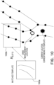
- FIG. 10 is a diagram illustrating an example of processing of the current location detector 207.
- An image 100a indicates an image most matched with the captured image in the processing of the matching portion 205.
- the image 100a is an image obtained by transforming an image 100b with a homography matrix H 0,T-3 .
- the homography matrix H 0,T-3 is a homography matrix corresponding to a predetermined distance from the set point (POL, P0R) in the image 100b. That is, when the most matched image 100a is selected by the processing in the matching portion 205, the current location where the image 100a has been captured can be accurately generated from the distance information corresponding to the homography matrix H 0,T-3 used in the generation of the image 100a. In this way, the current location detector 207 detects a location corresponding to the homography matrix H 0,T-3 that has been used in the transformation into the most matched template in the processing of the matching portion 205 as the current location.
- tongue-rail state monitor 209 Details of the tongue-rail state monitor 209 are explained below with reference to FIGS. 11 and 12 .
- FIG. 11 is a diagram illustrating a set point (PTL, PTR) including a tongue rail.
- An image 110a is an image range corresponding to the set point (PTL, PTR).
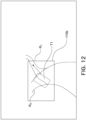
- FIG. 12 is a diagram illustrating line information obtained by transforming line information in the image 110a (see FIG. 11 ) corresponding to the set point (PTL, PTR) into the camera coordinate system. That is, the image 110b corresponds to the image 110a (see FIG. 11 ). That is, the image 110b corresponds to a template most matched in the matching portion 205.
- the tongue-rail state monitor 209 determines the state of the tongue rail. More specifically, the tongue-rail state monitor 209 analyzes, for example, image information in a captured image of an image region T1 including a branch associated with the set point (PTL, PTR) corresponding to the tongue rail (see Patent Literature 2). That is, the tongue-rail state monitor 209 identifies lines on which the railroad vehicle 5 travels by determining the on/off state of at least either of two switching parts in the tongue rail in the captured image on the basis of the image region T1 including a branch.
- the tongue-rail state monitor 209 acquires a signal including information related to the traveling direction, for example, from the central monitoring room. The tongue-rail state monitor 209 determines whether the traveling direction coincides with the identification result on the on/off state. When the traveling direction does not coincide with the identification result, the tongue-rail state monitor 209 notifies of abnormality in the tongue rail state via the notifier 50.
- FIG. 13 is a diagram illustrating an example in which a tunnel is included in an image captured by the image capturing portion 101. Exposure of the image capturing portion 101 has a value adjusted to the brightness of outside the tunnel. Accordingly, an image in the tunnel is liable to become blocked-up shadows.
- the parameter corrector 210 outputs a signal including information of parameters to the parameter setter 102 on the basis of the current location of the railroad vehicle 5 output from the current location detector 207.
- the storage portion 204 has also location information of the tunnel stored therein to be associated with the line information.
- the parameter corrector 210 determines whether a tunnel is included in an image captured by the image capturing portion 101 with respect to the current location of the railroad vehicle 5. When determining that an image of a tunnel is captured, the parameter corrector 210 outputs a parameter for decreasing the exposure to the parameter setter 102. More specifically, the parameter corrector 210 corrects the parameter to provide a predetermined contrast using the contrast of an adjustment area A130 in the tunnel as an evaluation value.
- the parameter corrector 210 also acquires state monitoring information of the tongue-rail state monitor 209.
- the parameter corrector 210 determines whether exposure control is required for an image in the tunnel according to the traveling direction. For example, when the railroad vehicle travels toward the tunnel, the parameter corrector 210 outputs a parameter for increasing exposure to the parameter setter 102. On the other hand, even when an image of the tunnel is captured by the image capturing portion 101, the parameter corrector 210 keeps the exposure parameter when the railroad vehicle does not travel toward the tunnel.
- the exposure can be adjusted to illuminance of the adjustment area A130 in the tunnel and obstacles in the adjustment area A130 in the tunnel can be easily checked.
- the exposure parameter is maintained even when an image of the tunnel is captured. Accordingly, obstacles in the traveling direction can be easily checked.
- FIG. 14 is a flowchart illustrating a flow of general processing of the railroad-vehicle travel-line acquiring system 1.
- the railroad-line information acquiring apparatus 20 checks a captured image that is captured by the image capturing device 10 on the basis of the location information of lines and detects line information in the captured image (Step S11).
- the obstacle detecting device 40 detects obstacles that will impede the railroad vehicle 5 during traveling, on the basis of the lines detected by the railroad-line information acquiring apparatus 20 and the captured image captured by the image capturing device 10 (Step S12).
- the tongue-rail state monitor 209 determines the state of the tongue rail (Step S13).
- the travel-location-information collecting device 30 corrects the current location to be output from the travel-location-information collecting device 30, assuming the current location of the railroad vehicle 5 detected by the current location detector 207 as the correct current location (Step S14).
- the parameter corrector 210 outputs a signal including information of parameters to the parameter setter 102 on the basis of the current location of the railroad vehicle 5 output from the current location detector 207 (Step S15), and the processing is ended.
- FIG. 15 is a flowchart illustrating a flow of detailed processing of the line detecting processing.
- the image acquirer 201 acquires a captured image in the traveling direction of the railroad vehicle 5 from the image capturing portion 101 (Step S110).
- the scheduled-travel-line location acquirer 202 acquires location information of lines in the direction in which the railroad vehicle 5 travels from the travel-location-information collecting device 30 (Step S112).
- the line coordinate transformer 203 transforms the captured image acquired by the image acquirer 20 and the location information of the lines into a common coordinate system (Step S113).
- the line coordinate transformer 203 transforms the captured image and the location information into the camera coordinate system.
- the matching portion 205 acquires location information of lines corresponding to the lines in the captured image, on the common coordinate system (Step S114).
- the line output portion 206 then outputs location information of lines coinciding with the lines in the captured image compared by the matching portion 205 (Step S115), and the processing is ended.
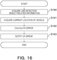
- FIG. 16 is a flowchart illustrating a flow of detailed processing of the current location correcting processing.
- the current location collector 301 acquires the current location of the railroad vehicle 5 output from the current location detector 207 as line detection result-related information (Step S140).
- the current location collector 301 acquires information of the current location of the railroad vehicle 5 on the basis of the GNSS (Global Navigation Satellite System) (Step S141).
- GNSS Global Navigation Satellite System
- the travel-location-information collecting device 30 calculates an error between the current location of the railroad vehicle 5 output from the current location detector 207 and the current location of the railroad vehicle 5 based on the GNSS (Step S142).
- the travel-location-information collecting device 30 corrects the output value on the basis of the current location of the railroad vehicle 5 output from the current location detector 207 and notifies of corrected information via the notifier 50 (Step S143), and the processing is ended.
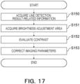
- FIG. 17 is a flowchart illustrating a flow of detailed processing of the imaging parameter correcting processing. An example in which parameters are corrected using the contrast in the captured image as an evaluation value is explained below.
- the parameter corrector 210 acquires the current location of the railroad vehicle 5 output by the current location detector 207 and the location information of tunnels included in an imaging range from the current location, as line detection result-related information (Step S150).
- the parameter corrector 210 acquires information of a brightness adjustment area A130 that is associated with the location information of each of the tunnels (Step S151).
- the parameter corrector 210 evaluates the contrast of the adjustment area A130 in the captured image (Step S151).
- the parameter corrector 210 outputs an exposure parameter for causing the contrast to have a predetermined value to the parameter setter 102 (Step S143), and the processing is ended.
- the line coordinate transformer 203 transforms the location information of lines in a predetermined range on a geographical coordinate system, which is acquired in advance and a captured image on a camera coordinate system, which is obtained by imaging the predetermined range, into a common coordinate system and the matching portion 205 acquires location information of lines on the geographical coordinate system corresponding to lines in the captured image. Accordingly, the location information of a line in the captured image corresponding to the location information of the line on the geographical coordinate system, which is acquired in advance can be obtained.
- transformation into the common coordinate system enables the location information of the line on the geographical coordinate system most matched as the whole line in the captured image to be acquired, and the location information of lines in the captured image can be more accurately acquired.
- the railroad-vehicle travel-line acquiring system 1 according to a second embodiment is different from the railroad-vehicle travel-line acquiring system 1 according to the first embodiment in that an image projector 203b transforms a captured image of the camera coordinate system into the geographical coordinate system. Differences from the railroad-vehicle travel-line acquiring system 1 according to the first embodiment are described below.
- FIG. 18 is a block diagram illustrating a configuration of the railroad-vehicle travel-line acquiring system 1 according to the second embodiment.
- the image projector 203b transforms a captured image on the camera coordinate system into the geographical coordinate system.
- the image projector 203b according to the present embodiment corresponds to a transformer.
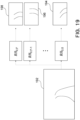
- FIG. 19 is a diagram illustrating inverse transformation matrixes RH 0,0 to RH 0,T of the homography matrixes H 0,0 to H 0,T corresponding to the set point (POL, P0R).
- An image 192 of the camera coordinate system is an image captured at the reference location for the set point (POL, P0R). Accordingly, when the image projector 203b inversely transforms the image 192 with the inverse transformation matrix RH 0,0 , a resultant image coincides with an image 194 of the geographical coordinate system corresponding to the set point (POL, P0R).
- images 196 and 198 of non-existent line information of the geographical coordinate system are generated.
- FIG. 20 is a diagram illustrating an example of inverse templates that are generated by the inverse coordinate transformation by the image projector 203b.
- FIG. 20 illustrates images obtained by inversely transforming the line information of the image 902 of the camera coordinate system with the inverse transformation matrixes RH 0,0 to RH n,T of the homography matrixes H 0,0 to H n,T , respectively.
- inverse template R(n, T) line information obtained by transformation into the geographical coordinate system (X, Y) with the inverse transformation matrix RH n,T of the homography matrix.
- the image projector 203b Considering a range in which the location of the railroad vehicle 5 includes an error, the image projector 203b generates inverse templates R(0, T) to R(n, T) respectively corresponding to the set points (POL, P0R) to (PnL, PnR) in a range in which the railroad vehicle 5 has a possibility of imaging.
- the matching portion 205 selects an inverse template most matched with the line information of the geographical coordinate system corresponding to the set points (POL, P0R) to (PnL, PnR), for example, using the inverse templates R(0, T) to R(n, T) generated by inverse coordinate transformation with the inverse transformation matrix RH of the homography matrix illustrated in FIG. 20 .
- the line output portion 206 outputs the location information of lines of the geographical coordinate system in the most matched inverse template as the line location information in the captured image 902.
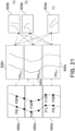
- FIG. 21 is a diagram illustrating an example of processing of the line output portion 206.
- Images 904b to 908b are captured images that are captured at times T1 to T3, respectively, and images 904c to 908c indicate most matched inverse templates, respectively.
- the image 904c corresponds to an inverse template generated by transformation with the inverse matrix RH 0,0 corresponding to the set point (POL, P0R). That is, the line output portion 206 outputs line information of the geographical coordinate system (X, Y) corresponding to the set point (POL, P0R) with respect to the captured image 904b captured at the time T1.
- the image 906c corresponds to an inverse template generated by transformation with an inverse matrix RH 3,T-1 corresponding to the set point (P3L, P3R). That is, the line output portion 206 outputs line information of the geographical coordinate system (X, Y) corresponding to the set point (P3L, P3R) with respect to the captured image 906b captured at the time T2.
- the image 908c corresponds to an inverse template generated by transformation with an inverse matrix RH 6,2 corresponding to the set point (P6L, P6R). That is, the line output portion 206 outputs line information of the geographical coordinate system (X, Y) corresponding to the set point (P6L, P6R) with respect to the image 908b captured at the time T3.
- the current location detector 207 detects a location corresponding to the inverse transformation matrix RH n,T used in the transformation into the most matched inverse template by the processing in the matching portion 205, as the current location. For example, when an inverse template generated by transformation with the inverse matrix RH 2,T-1 most matches with the image, the current location detector 207 detects the distance corresponding to T-1 as the current location of the railroad vehicle 5 with respect to the set point (P3L, P3R).
- FIG. 22 is a flowchart illustrating a flow of detailed processing of the current location detecting processing according to the second embodiment.
- the image acquirer 201 acquires a captured image in the traveling direction of the railroad vehicle 5 from the image capturing portion 101 (Step S220).
- the scheduled-trave-line location acquirer 202 acquires location information of lines in the direction in which the railroad vehicle 5 travels from the travel-location-information collecting device 30 (Step S221).
- the image projector 203b transforms the captured image acquired by the image acquirer 20 and the location information of lines into a common coordinate system (Step S222).
- the image projector 203b transforms the captured image and the location information into the geographical coordinate system with the inverse transformation matrix RH of the homography matrix.
- the matching portion 205 acquires location information of lines corresponding to the lines in the captured image, on the common coordinate system (Step S223).
- the line output portion 206 outputs the location information of the lines (Step S223), and the entire processing is ended.
- the image projector 203b transforms a captured image of the camera coordinate system, obtained by imaging a predetermined range, into the geographical coordinate system and the matching portion 205 acquires location information of lines on the geographical coordinate system, that corresponds to lines in the captured image and that is acquired in advance. Accordingly, the location information of lines in a captured image corresponding to the location information of lines acquired in advance can be acquired.
- the railroad-vehicle travel-line acquiring system 1 according to a third embodiment is different from the railroad-vehicle travel-line acquiring system 1 according to the first embodiment in that location information on the geographical coordinate system is stored as coordinates of three axes (X, Y, Z). Differences from the railroad-vehicle travel-line acquiring system 1 according to the first embodiment are described below.
- the camera used by the image capturing portion 101 is a stereo camera and an image on the camera coordinate system is also generated as coordinates of three axes (x, y, z).
- FIG. 23 is a flowchart illustrating a flow of detailed processing of line detecting processing according to the third embodiment.
- the image acquirer 201 acquires a stereo captured image in the traveling direction of the railroad vehicle 5 from the image capturing portion 101 (Step S230).
- the scheduled-travel-line location acquirer 202 acquires location information of lines in the direction in which the railroad vehicle 5 travels from the travel-location-information collecting device 30 (Step S231).
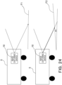
- FIG. 24 is a diagram schematically illustrating an example in which the railroad vehicle 5 travels on a horizontal face F1 and a tilted face F2 at a tilt ⁇ with respect to the horizontal face F1.
- a z-coordinate value according to the tilt is allocated to each of pixels of a stereo image captured from the railroad vehicle 5 traveling on the tilted face F2.
- the line coordinate transformer 203 can compute the tilt from the z-coordinate of the front side of the image and the z-coordinate of the back side thereof (Step S232).
- the line coordinate transformer 203 restricts location information to that of lines having tilts in a predetermined range with respect to the computed tilt (Step S234), and transforms the captured image acquired by the image acquirer 20 and the location information of lines into a common coordinate system (Step S113).
- the line coordinate transformer 203 transforms the captured image and the location information into a camera coordinate system in a horizontal plane using altitude information as a value in the Z-axis direction.
- the image transformed into the camera coordinate system is a so-called bird's-eye view.
- the matching portion 205 acquires location information of lines corresponding to lines in the captured image, on the common coordinate system (Step S114). By transforming location information of lines different in the tilt into a bird's-eye view being a horizontal face, influences of the tilts are suppressed and the matching in the matching portion 205 can be performed more accurately.
- the line output portion 206 outputs location information of lines coinciding with the lines in the captured image compared by the matching portion 205 (Step S115), and the processing is ended.
- the line information on the geographical coordinate system of three axes is stored as (X, Y, Z) and a stereo captured image on the camera coordinate system of three axes is used.
- This enables the line coordinate transformer 203 to restrict previously-acquired location information of lines in a predetermined range, using tilt information of a stereo captured image. Accordingly, information is restricted when the matching portion 205 acquires location information of lines corresponding to lines in the captured image, and location information of lines in the captured image corresponding to previously-acquired location information of lines can be acquired more quickly and more accurately.
Landscapes
- Engineering & Computer Science (AREA)
- Mechanical Engineering (AREA)
- Physics & Mathematics (AREA)
- General Physics & Mathematics (AREA)
- Multimedia (AREA)
- Theoretical Computer Science (AREA)
- Train Traffic Observation, Control, And Security (AREA)
- Image Analysis (AREA)
- Image Processing (AREA)
Abstract
Description
- Embodiments of the present invention relate to a railroad-line information acquiring apparatus and a railroad-line information acquiring method.
- A monitoring method of monitoring obstacles ahead using images captured by a camera mounted on a railroad vehicle is generally known. This monitoring method determines whether an object located ahead is an obstacle that the vehicle may hit. Therefore, processing of detecting lines on which the vehicle is supposed to travel in images is required. Since the braking distance for the railroad vehicle to stop is long, detecting farther lines with a high accuracy and at a high speed is demanded.
- However, lines are not clearly imaged depending on the weather, the time period, and the environments (such as a tunnel) and there is a risk that detecting lines in the distance with a high accuracy becomes difficult.
-
- Patent Literature 1:
Japanese Patent Application Laid-open No. 2016-172824 - Patent Literature 2:
Japanese Patent Application Laid-open No. 2019-218022 - Non Patent Literature 1: Conference: 2016 12th World Congress on Intelligent Control and Automation (WCICA), "Geometry Constraints-based Visual Rail Track Extraction"
- To provide a railroad-line information acquiring apparatus and a railroad-line information acquiring method that can detect location information of lines with a higher accuracy.
- A railroad-line information acquiring apparatus according to the present embodiment includes an image acquirer, a line information acquirer, a transformer, and a comparator. The image acquirer acquires a captured image in a traveling direction of a railroad vehicle. The line information acquirer acquires location information of a first line in a direction in which the railroad vehicle travels, on the basis of a location of the railroad vehicle. The transformer transforms the captured image and the first line into a common coordinate system. The comparator acquires location information of the first line corresponding to a second line in the captured image, on the common coordinate system.
-
- [
FIG. 1] FIG. 1 is a block diagram illustrating a configuration example of a railroad-line information acquiring apparatus. - [
FIG. 2] FIG. 2 is a block diagram illustrating a detailed configuration example of the railroad-line information acquiring apparatus according to the present embodiment. - [
FIG. 3] FIG. 3 is a diagram illustrating lines shown on a horizontal plane. - [
FIG. 4] FIG. 4 is a diagram illustrating a relation among the latitude and longitude at a midpoint between lines, and a set point. - [
FIG. 5] FIG. 5 is a diagram schematically illustrating locations of the set points set on the lines. - [
FIG. 6] FIG. 6 is a diagram for schematically explaining homography matrixes for the set points. - [
FIG. 7] FIG. 7 is a diagram illustrating an example of coordinate transformation using the homography matrixes corresponding to a set point. - [
FIG. 8] FIG. 8 is a diagram illustrating an example of templates generated by coordinate transformation by a line coordinate transformer. - [
FIG. 9] FIG. 9 is a diagram illustrating an example of processing of a line output portion. - [
FIG. 10] FIG. 10 is a diagram illustrating an example of processing of a current location detector. - [
FIG. 11] FIG. 11 is a diagram illustrating a set point including a tongue rail. - [
FIG. 12] FIG. 12 is a diagram illustrating line information obtained by transforming line information corresponding to the set point into a camera coordinate system. - [
FIG. 13] FIG. 13 is a diagram illustrating an example in which a tunnel is included in an image captured by an image capturing portion. - [
FIG. 14] FIG. 14 is a flowchart illustrating a flow of general processing of the railroad-line information acquiring apparatus. - [
FIG. 15] FIG. 15 is a flowchart illustrating a flow of detailed processing of line detecting processing. - [
FIG. 16] FIG. 16 is a flowchart illustrating a flow of detailed processing of current location correcting processing. - [
FIG. 17] FIG. 17 is a flowchart illustrating a flow of detailed processing of imaging parameter correcting processing. - [
FIG. 18] FIG. 18 is a block diagram illustrating a configuration of a railroad-line information acquiring apparatus according to a second embodiment. - [
FIG. 19] FIG. 19 is a diagram illustrating inverse transformation matrixes of homography matrixes corresponding to the set point. - [
FIG. 20] FIG. 20 is a diagram illustrating an example of inverse templates that are generated by inverse coordinate transformation by an image projector. - [
FIG. 21] FIG. 21 is a diagram illustrating an example of processing of the line output portion. - [
FIG. 22] FIG. 22 is a flowchart illustrating a flow of detailed processing of current location detecting processing according to the second embodiment. - [
FIG. 23] FIG. 23 is a flowchart illustrating a flow of detailed processing of line detecting processing according to a third embodiment. - [
FIG. 24] FIG. 24 is a diagram schematically illustrating an example in which a railroad vehicle travels on a horizontal face and a tilted face. - Embodiments of the present invention will now be explained below with reference to the drawings. In the drawings attached to the present specification, the scale, the aspect ratio, and the like of the respective constituent elements are changed from those of actual products and illustrated in an exaggerated manner as appropriate for convenience of illustration and understanding.
-
FIG. 1 is a block diagram illustrating a configuration example of a railroad-vehicle travel-line acquiring system 1 according to the present embodiment. As illustrated inFIG. 1 , the railroad-vehicle travel-line acquiring system 1 according to the present embodiment is a system that can acquire location information of railroad vehicle travel lines and includes an image capturingdevice 10 mounted on arailroad vehicle 5, a railroad-lineinformation acquiring apparatus 20, a travel-location-information collecting device 30, anobstacle detecting device 40, and anotifier 50. Therailroad vehicle 5 travels on lines being a fixed track. - The image capturing
device 10 can serially capture R, G, and B images as a captured moving image. The image capturingdevice 10 is fixed, for example, to a front portion of therailroad vehicle 5. Accordingly, images constituting a captured moving image captured during traveling of therailroad vehicle 5 on the lines are, for example, images from the same angle and with the same imaging magnification when captured at the same location. These images are stored in astorage portion 204 which will be described later. - The railroad-line
information acquiring apparatus 20 checks the captured images that are captured by theimage capturing device 10 against location information of lines, detects location information of the lines in the captured images, and outputs the detected information. Details of the railroad-lineinformation acquiring apparatus 20 will be described later. - The travel-location-information collecting
device 30 acquires the current location of therailroad vehicle 5 and outputs information of a predetermined line range in the traveling direction of therailroad vehicle 5 for the current location. - The
obstacle detecting device 40 detects obstacles that will impede therailroad vehicle 5 during traveling, on the basis of the captured images captured by theimage capturing device 10 and the lines detected by the railroad-lineinformation acquiring apparatus 20. - The
notifier 50 displays various types of information along with the captured images captured by theimage capturing device 10. Thenotifier 50 also notifies, for example, a central monitoring room of information related to the obstacles detected by theobstacle detecting device 40. -
FIG. 2 is a block diagram illustrating a detailed configuration example of the railroad-vehicle travel-line acquiring system 1 according to the present embodiment. As illustrated inFIG. 2 , theimage capturing device 10 includes animage capturing portion 101, and aparameter setter 102. The railroad-lineinformation acquiring apparatus 20 includes animage acquirer 201, a scheduled-travel-line location acquirer 202, a line coordinatetransformer 203, thestorage portion 204, a matchingportion 205, aline output portion 206, acurrent location detector 207, a currentlocation output portion 208, a tongue-rail state monitor 209, and animaging parameter corrector 210. The travel-location-information collecting device 30 includes acurrent location collector 301, and a travel-line output portion 302. Theobstacle detecting device 40 includes a line-location andimage acquirer 401, and atravel obstacle detector 402. Thenotifier 50 includes adisplay portion 501, and anabnormality notifier 502. - As illustrated in
FIG. 2 , theimage capturing portion 101 of theimage capturing device 10 is, for example, a camera and can control exposure. Theparameter setter 102 sets imaging parameters of theimage capturing portion 101. Theparameter setter 102 can also perform gradation processing for images captured by theimage capturing portion 101. - The
image acquirer 201 of the railroad-lineinformation acquiring apparatus 20 sequentially acquires captured images in the traveling direction of therailroad vehicle 5 from theimage capturing portion 101. The scheduled-travel-line location acquirer 202 acquires location information of lines in the direction in which therailroad vehicle 5 travels from the travel-location-information collecting device 30. The railroad-lineinformation acquiring apparatus 20 is configured, for example, to include a CPU (Central Processing Unit). Thestorage portion 204 has stored therein various programs to enable a monitoring operation to be performed. Accordingly, the railroad-lineinformation acquiring apparatus 20 configures components by executing, for example, the programs stored in thestorage portion 204. - The line coordinate
transformer 203 transforms the captured image acquired by theimage acquirer 20 and the location information of lines into a common coordinate system. For example, the line coordinatetransformer 203 transforms coordinates of the lines indicated by the location information into a camera coordinate system of theimage capturing portion 101 that has captured the captured image. Details of the line coordinatetransformer 203 will be described later. The line coordinatetransformer 203 according to the present embodiment corresponds to a transformer. - The
storage portion 204 is constituted of, for example, an HDD (Hard Disk Drive) or an SSD (Solid State Drive). Thestorage portion 204 has stored therein the location information of lines as a monitoring target, a coordinate transformation matrix for the lines as the monitoring target, various types of information of theimage capturing portion 101, for example, the direction of the optical axis of an imaging optical system, and the imaging magnification, as coordinate transformation information. - The matching
portion 205 acquires location information of lines corresponding to the lines in the captured image, on the common coordinate system. Details of the matchingportion 205 will also be described later. The matchingportion 205 according to the present embodiment corresponds to a comparator. - The
line output portion 206 outputs the location information of the lines coinciding with the lines in the captured image compared by the matchingportion 205. - The
current location detector 207 calculates a current location of therailroad vehicle 5 using the location information of the lines acquired by the matchingportion 205 and the information of the imaging optical system of theimage capturing portion 101. Details of thecurrent location detector 207 will also be described later. The current-location output portion 208 outputs the current location detected by thecurrent location detector 207. - The tongue-rail state monitor 209 monitors the state of tongue rails at line branch parts and checks the state against the travel line location information to confirm consistency in the tongue rail state. Details of the tongue-rail state monitor 209 will also be described later.
- The
imaging parameter corrector 210 corrects imaging parameters in the traveling direction of therailroad vehicle 5 using the location information of the lines acquired by the matchingportion 205. Details of theimaging parameter corrector 210 will also be described later. - The
current location collector 301 of the travel-location-information collecting device 30 acquires the current location of therailroad vehicle 5 output by thecurrent location detector 207. Thecurrent location collector 301 also acquires information of the current location of therailroad vehicle 5 based on the GNSS (Global Navigation Satellite System). Accordingly, the travel-location-information collecting device 30 outputs a signal including information of the current location of therailroad vehicle 5 to the travel-line output portion 302 complementarily using the current location of therailroad vehicle 5 output by thecurrent location detector 207 and the current location of therailroad vehicle 5 based on the GNSS. - The travel-
line output portion 302 outputs information of line locations in a predetermined range in the traveling direction of therailroad vehicle 5 on the basis of the current location of therailroad vehicle 5 acquired by thecurrent location collector 301. The predetermined range is, for example, a range of 50 to 200 meters ahead in the traveling direction. The range of 50 to 200 meters is an example and the predetermined range is not limited to this range. - The line-location and
image acquirer 401 of theobstacle detecting device 40 acquires the captured image captured by theimage capturing portion 101 and the location information of lines in the captured image compared by the matchingportion 205. - The
travel obstacle detector 402 detects obstacles that will impede the traveling of therailroad vehicle 5 on the basis of the location information of the lines in the captured image. When detecting an obstacle, thetravel obstacle detector 402 notifies thenotifier 50 of the location of the obstacle based on the location information of the lines in the captured image. - The
display portion 501 of thenotifier 50 is, for example, a monitor and displays the captured image captured by theimage capturing portion 101. When thetravel obstacle detector 402 detects an obstacle, thedisplay portion 501 displays a display form such as a mark indicating the location of the obstacle. - When the
travel obstacle detector 402 detects an obstacle, theabnormality notifier 502 notifies the central monitoring room, or the like, of information indicating the location of the obstacle, or the like. - Details of the line coordinate
transformer 203 are explained below with reference toFIGS. 3 to 8 .FIG. 3 is a diagram illustrating lines R0 and R1 shown on a horizontal plane, for example, on a bird's-eye view. As illustrated inFIG. 3 , the lines R1 branch off from the lines R0. Thestorage portion 204 has stored therein location information of lines in the whole range in which therailroad vehicle 5 travels, for example, represented by a geographical coordinate system (X, Y). -
FIG. 4 is a diagram illustrating a relation among the latitude and longitude at a midpoint between lines, and the set point (PnL, PnR). As illustrated inFIG. 4 , for example, the latitude and longitude at the midpoint between lines, and the set point (PnL, PnR) are stored in thestorage portion 204 associated with each other. In this example, n is a natural number, L indicates a left line with respect to the traveling direction, and R indicates a right line with respect to the traveling direction. That is, PnL indicates the location of the left line and PnR indicates the location of the right line corresponding to PnL. As described later, a homography matrix Hn,T is associated with each of the set points (PnL, PnR) and is stored. The homography matrix H in the present embodiment is a matrix for associating the geography coordinate system (X, Y) with the camera coordinate system (x, y) of theimage capturing portion 101. -
FIG. 5 is a diagram schematically illustrating locations of the set points (PnL, PnR) set on the lines R0 and R1. In this way, the latitude, the longitude, and the set point (PnL, PnR) are associated with each of the lines in the whole range in which therailroad vehicle 5 travels. -
FIG. 6 is a diagram for schematically explaining the homography matrixes Hn,T for the set points (PnL, PnR). These homography matrixes H can be respectively computed for the set points (PnL, PnR), for example, by a technique described inNon Patent Literature 1. In this example, n in Hn,T indicates the set point (PnL, PnR). For example, when n=3, this indicates the set point (P3L, P3R). - An
image 500a is a captured image that is captured by theimage capturing portion 101 from the location of therailroad vehicle 5 supposed at the time of calculating the homography matrix Hn,T. An image 500b indicates a range of line information transformed with the homography matrix Hn,T for the set point (PnL, PnR). T indicates the distance from the set point (PnL, PnR) to theimage capturing portion 101 of therailroad vehicle 5. For example, 0 (zero) indicates a reference distance from the set point (PnL, PnR) to theimage capturing portion 101 of therailroad vehicle 5 and is, for example, 100 meters. For example, when T=1, the distance from the set point (PnL, PnR) to theimage capturing portion 101 is 101 meters. For example, when T=5, the distance from the set point (PnL, PnR) to theimage capturing portion 101 is 105 meters. Meanwhile, for example, when T=-1, the distance from the set point (PnL, PnR) to theimage capturing portion 101 is 99 meters. For example, when T=-5, the distance from the set point (PnL, PnR) to theimage capturing portion 101 is 95 meters. These are examples and the value of T and the corresponding distance are not limited to these examples. - As described above, the geographical coordinate system (X, Y) is set to the line information stored in the
storage portion 204. Theimage capturing portion 101 captures images with the fixed imaging system as described above. Accordingly, the geographical coordinate system (X, Y) of a line transformed with the homography matrix H into the camera coordinates (x, y) coincides with a location indicated by the camera coordinate system of the line in theimage 500a captured from the location of therailroad vehicle 5 supposed at the time of calculating the homography matrix Hn,T. That is, the geographical coordinate system (X, Y) of a line with coordinates transformed with the homography matrix Hn,T is transformed into the location coordinates (x, y) indicated by the camera coordinate system of the line in theimage 500a captured from the distance corresponding to T. -
FIG. 7 is a diagram illustrating an example of coordinate transformation by the line coordinatetransformer 203 using the homography matrixes H0,0 to H0,T corresponding to the set point (POL, P0R). Animage 802 is an image region corresponding to the set point (POL, P0R) and indicates line information indicated by the geographical coordinate system (X, Y). Each ofimages 804 to 808 indicates line information obtained by transforming the line information indicated by the geographical coordinate system (X, Y) in theimage 802 into the camera coordinate system (x, y) with the associated one of the homography matrixes H0,0 to H0,T. - More specifically, H0,0 indicates a homography matrix at a reference location where the distance from the set point (POL, P0R) to the
image capturing portion 101 of therailroad vehicle 5 is the reference distance, for example, at a location 100 meters short of the set point (POL, P0R). Line information indicated by the camera coordinates (x, y) in theimage 804 corresponds to line information obtained by transforming the line information indicated by the geographical coordinate system (X, Y) in theimage 802 corresponding to the set point (POL, P0R) into camera coordinates with the homography matrix H0,0. That is, the line information indicated by the camera coordinates (x, y) in theimage 804 coincides with location coordinates on the camera coordinate system of lines in an image obtained by imaging a region corresponding to theimage 802 with theimage capturing portion 101 at the reference location. - Similarly, line information indicated by the camera coordinates (x, y) in the
image 806 corresponds to line information obtained by transforming the line information indicated by the geographical coordinate system (X, Y) in theimage 802 corresponding to the set point (POL, P0R) into camera coordinates with the homography matrix H0,T-1. That is, the line information indicated by the camera coordinates (x, y) in theimage 806 coincides with location coordinates on the camera coordinate system of lines in an image obtained by imaging a region corresponding to theimage 802 with theimage capturing portion 101 at a location indicated by T-1. Similarly, line information indicated by the camera coordinates (x, y) in theimage 808 corresponds to line information obtained by transforming the line information indicated by the geographical coordinate system (X, Y) in theimage 802 corresponding to the set point (POL, P0R) into camera coordinates with the homography matrix H0,T. That is, the line information indicated by the camera coordinates (x, y) in theimage 808 coincides with location coordinates on the camera coordinate system of lines in an image obtained by imaging a region corresponding to theimage 802 with theimage capturing portion 101 at a location indicated by T. In this way, the line coordinatetransformer 203 transforms line information indicated by the geographical coordinate system (X, Y) in theimage 802 corresponding to the set point (POL, P0R) with the associated homography matrix H0,T. In this example, T is an integer in a range of -n≤T≤m set according to imaging situations, where n and m are natural numbers. - Accordingly, the line coordinate
transformer 203 can transform a region corresponding to theimage 802 into location coordinates of lines on the camera coordinate system captured from each of a plurality of imaging locations T. In the present embodiment, line information on the geographical coordinate system (X, Y) corresponding to the set point (PnL, PnR) is transformed into the camera coordinate system (x, y) with the homography matrix Hn,T and the resultant line information on the camera coordinate system (x, y) is referred to as "template (n, T)". -
FIG. 8 is a diagram illustrating an example of templates generated by coordinate transformation by the line coordinatetransformer 203. The location of therailroad vehicle 5 output from the travel-location-information collecting device 30 may include an error. Therefore, considering a range in which an error occurs, the travel-location-information collecting device 30 generates templates (0, 0) to (n, T) respectively corresponding to the set points (POL, P0R) to (PnL, PnR) in a range in which there is a possibility for therailroad vehicle 5 to capture images. - It is assumed below that the current location of the
railroad vehicle 5 at a time when the capturedimage 902 has been captured is the reference location of the set point (POL, P0R). In this case, the line coordinatetransformer 203 generates line information by transforming line information on the geographical coordinate system (X, Y) corresponding to the set point (POL, P0R) into the camera coordinate system (x, y) with the associated homography matrix H0,T. Similarly, the line coordinatetransformer 203 generates line information by transforming line information on the geographical coordinate system (X, Y) corresponding to each of the set points (P1L, P1R) to (PnL, PnR) into the camera coordinate system (x, y) with the associated homography matrixes H1,0 to H1,T, respectively. The ranges of n and T are set in advance based on measurement accuracy of the current location of therailroad vehicle 5. - The matching
portion 205 detects lines from the capturedimage 902, for example, using the templates (0, T) to (n, T) generated by the coordinate transformation with the homography matrixes H illustrated inFIG. 8 . The matchingportion 205 expresses, for example, the lines in the capturedimage 902 as line components obtained by coupling short straight lines and curved segments. The matchingportion 205 selects a template most matched with the line components from the templates (0, T) to (n, T). - The
line output portion 206 outputs the location information of lines in the most matched template as line location information in the capturedimage 902. -
FIG. 9 is a diagram illustrating an example of processing of theline output portion 206.Images 904b to 908b indicate templates most matched with captured images that are captured at times T1 to T3, respectively. For example, theimage 904b corresponds to a template generated by transformingline information 904a corresponding to the set point (POL, P0R) with the homography matrix H0,0. That is, theline output portion 206 outputs line information indicated by theimage 904b that has been transformed into the camera coordinate system (x, y) for the captured image captured at the time T1. Similarly, theimage 906b corresponds to a template generated by transformingline information 906a corresponding to the set point (P3L, P3R) with a homography matrix H3,T-1. That is, theline output portion 206 outputs line information indicated by theimage 906b that has been transformed into the camera coordinate system (x, y) for the captured image captured at the time T2. Similarly, theimage 908b corresponds to a template generated by transformingline information 908a corresponding to a set point (P6L, P6R) with a homography matrix H6,2. That is, theline output portion 206 outputs line information indicated by theimage 908b that has been transformed into the camera coordinate system (x, y) for the captured image captured at the time T3. - Since these
images 904b to 908b are images generated by transforming theactual line information 904a to 908a, respectively, the line information of the camera coordinate system (x, y) output from theline output portion 206 substantially coincides with the actual line information. Therefore, theline output portion 206 can output line information corresponding to the actual lines from each of the captured images that are captured at the times T1 to T3. -
FIG. 10 is a diagram illustrating an example of processing of thecurrent location detector 207. Animage 100a indicates an image most matched with the captured image in the processing of the matchingportion 205. Theimage 100a is an image obtained by transforming animage 100b with a homography matrix H0,T-3. The homography matrix H0,T-3 is a homography matrix corresponding to a predetermined distance from the set point (POL, P0R) in theimage 100b. That is, when the most matchedimage 100a is selected by the processing in the matchingportion 205, the current location where theimage 100a has been captured can be accurately generated from the distance information corresponding to the homography matrix H0,T-3 used in the generation of theimage 100a. In this way, thecurrent location detector 207 detects a location corresponding to the homography matrix H0,T-3 that has been used in the transformation into the most matched template in the processing of the matchingportion 205 as the current location. - Details of the tongue-rail state monitor 209 are explained below with reference to
FIGS. 11 and12 . -
FIG. 11 is a diagram illustrating a set point (PTL, PTR) including a tongue rail. Animage 110a is an image range corresponding to the set point (PTL, PTR). -
FIG. 12 is a diagram illustrating line information obtained by transforming line information in theimage 110a (seeFIG. 11 ) corresponding to the set point (PTL, PTR) into the camera coordinate system. That is, theimage 110b corresponds to theimage 110a (seeFIG. 11 ). That is, theimage 110b corresponds to a template most matched in the matchingportion 205. - When the set point (PTL, PTR) corresponding to the template most matched in the matching
portion 205 includes a tongue rail, the tongue-rail state monitor 209 determines the state of the tongue rail. More specifically, the tongue-rail state monitor 209 analyzes, for example, image information in a captured image of an image region T1 including a branch associated with the set point (PTL, PTR) corresponding to the tongue rail (see Patent Literature 2). That is, the tongue-rail state monitor 209 identifies lines on which therailroad vehicle 5 travels by determining the on/off state of at least either of two switching parts in the tongue rail in the captured image on the basis of the image region T1 including a branch. The tongue-rail state monitor 209 acquires a signal including information related to the traveling direction, for example, from the central monitoring room. The tongue-rail state monitor 209 determines whether the traveling direction coincides with the identification result on the on/off state. When the traveling direction does not coincide with the identification result, the tongue-rail state monitor 209 notifies of abnormality in the tongue rail state via thenotifier 50. - Details of the
parameter corrector 210 are explained below with reference toFIG. 13. FIG. 13 is a diagram illustrating an example in which a tunnel is included in an image captured by theimage capturing portion 101. Exposure of theimage capturing portion 101 has a value adjusted to the brightness of outside the tunnel. Accordingly, an image in the tunnel is liable to become blocked-up shadows. - The
parameter corrector 210 outputs a signal including information of parameters to theparameter setter 102 on the basis of the current location of therailroad vehicle 5 output from thecurrent location detector 207. Thestorage portion 204 has also location information of the tunnel stored therein to be associated with the line information. Theparameter corrector 210 determines whether a tunnel is included in an image captured by theimage capturing portion 101 with respect to the current location of therailroad vehicle 5. When determining that an image of a tunnel is captured, theparameter corrector 210 outputs a parameter for decreasing the exposure to theparameter setter 102. More specifically, theparameter corrector 210 corrects the parameter to provide a predetermined contrast using the contrast of an adjustment area A130 in the tunnel as an evaluation value. - The
parameter corrector 210 also acquires state monitoring information of the tongue-rail state monitor 209. When there is a tunnel on one of branched lines and there is no tunnel on the other line, theparameter corrector 210 determines whether exposure control is required for an image in the tunnel according to the traveling direction. For example, when the railroad vehicle travels toward the tunnel, theparameter corrector 210 outputs a parameter for increasing exposure to theparameter setter 102. On the other hand, even when an image of the tunnel is captured by theimage capturing portion 101, theparameter corrector 210 keeps the exposure parameter when the railroad vehicle does not travel toward the tunnel. In this way, when the railroad vehicle travels toward a tunnel, the exposure can be adjusted to illuminance of the adjustment area A130 in the tunnel and obstacles in the adjustment area A130 in the tunnel can be easily checked. On the other hand, when the railroad vehicle does not travel toward the tunnel, the exposure parameter is maintained even when an image of the tunnel is captured. Accordingly, obstacles in the traveling direction can be easily checked. -
FIG. 14 is a flowchart illustrating a flow of general processing of the railroad-vehicle travel-line acquiring system 1. As illustrated inFIG. 14 , first, the railroad-lineinformation acquiring apparatus 20 checks a captured image that is captured by theimage capturing device 10 on the basis of the location information of lines and detects line information in the captured image (Step S11). - Next, the
obstacle detecting device 40 detects obstacles that will impede therailroad vehicle 5 during traveling, on the basis of the lines detected by the railroad-lineinformation acquiring apparatus 20 and the captured image captured by the image capturing device 10 (Step S12). - Subsequently, when a set point corresponding to the most matched template that is selected by the
mating portion 205 includes a tongue rail, the tongue-rail state monitor 209 determines the state of the tongue rail (Step S13). - Next, the travel-location-
information collecting device 30 corrects the current location to be output from the travel-location-information collecting device 30, assuming the current location of therailroad vehicle 5 detected by thecurrent location detector 207 as the correct current location (Step S14). - The
parameter corrector 210 outputs a signal including information of parameters to theparameter setter 102 on the basis of the current location of therailroad vehicle 5 output from the current location detector 207 (Step S15), and the processing is ended. -
FIG. 15 is a flowchart illustrating a flow of detailed processing of the line detecting processing. As illustrated inFIG. 15 , first, theimage acquirer 201 acquires a captured image in the traveling direction of therailroad vehicle 5 from the image capturing portion 101 (Step S110). - Next, the scheduled-travel-
line location acquirer 202 acquires location information of lines in the direction in which therailroad vehicle 5 travels from the travel-location-information collecting device 30 (Step S112). - Subsequently, the line coordinate
transformer 203 transforms the captured image acquired by theimage acquirer 20 and the location information of the lines into a common coordinate system (Step S113). In this example, the line coordinatetransformer 203 transforms the captured image and the location information into the camera coordinate system. - Next, the matching
portion 205 acquires location information of lines corresponding to the lines in the captured image, on the common coordinate system (Step S114). - The
line output portion 206 then outputs location information of lines coinciding with the lines in the captured image compared by the matching portion 205 (Step S115), and the processing is ended. -
FIG. 16 is a flowchart illustrating a flow of detailed processing of the current location correcting processing. As illustrated inFIG. 16 , first, thecurrent location collector 301 acquires the current location of therailroad vehicle 5 output from thecurrent location detector 207 as line detection result-related information (Step S140). - Next, the
current location collector 301 acquires information of the current location of therailroad vehicle 5 on the basis of the GNSS (Global Navigation Satellite System) (Step S141). - Next, the travel-location-
information collecting device 30 calculates an error between the current location of therailroad vehicle 5 output from thecurrent location detector 207 and the current location of therailroad vehicle 5 based on the GNSS (Step S142). - Subsequently, when the error exceeds a predetermined value, the travel-location-
information collecting device 30 corrects the output value on the basis of the current location of therailroad vehicle 5 output from thecurrent location detector 207 and notifies of corrected information via the notifier 50 (Step S143), and the processing is ended. -
FIG. 17 is a flowchart illustrating a flow of detailed processing of the imaging parameter correcting processing. An example in which parameters are corrected using the contrast in the captured image as an evaluation value is explained below. - As illustrated in
FIG. 17 , first, theparameter corrector 210 acquires the current location of therailroad vehicle 5 output by thecurrent location detector 207 and the location information of tunnels included in an imaging range from the current location, as line detection result-related information (Step S150). - Next, the
parameter corrector 210 acquires information of a brightness adjustment area A130 that is associated with the location information of each of the tunnels (Step S151). - Subsequently, the
parameter corrector 210 evaluates the contrast of the adjustment area A130 in the captured image (Step S151). - The
parameter corrector 210 outputs an exposure parameter for causing the contrast to have a predetermined value to the parameter setter 102 (Step S143), and the processing is ended. - As described above, according to the present embodiment, the line coordinate
transformer 203 transforms the location information of lines in a predetermined range on a geographical coordinate system, which is acquired in advance and a captured image on a camera coordinate system, which is obtained by imaging the predetermined range, into a common coordinate system and the matchingportion 205 acquires location information of lines on the geographical coordinate system corresponding to lines in the captured image. Accordingly, the location information of a line in the captured image corresponding to the location information of the line on the geographical coordinate system, which is acquired in advance can be obtained. In this way, also when a line in a captured image on the camera coordinate system is not clearly imaged, transformation into the common coordinate system enables the location information of the line on the geographical coordinate system most matched as the whole line in the captured image to be acquired, and the location information of lines in the captured image can be more accurately acquired. - The railroad-vehicle travel-
line acquiring system 1 according to a second embodiment is different from the railroad-vehicle travel-line acquiring system 1 according to the first embodiment in that animage projector 203b transforms a captured image of the camera coordinate system into the geographical coordinate system. Differences from the railroad-vehicle travel-line acquiring system 1 according to the first embodiment are described below. -
FIG. 18 is a block diagram illustrating a configuration of the railroad-vehicle travel-line acquiring system 1 according to the second embodiment. As illustrated inFIG. 18 , theimage projector 203b transforms a captured image on the camera coordinate system into the geographical coordinate system. Theimage projector 203b according to the present embodiment corresponds to a transformer. -
FIG. 19 is a diagram illustrating inverse transformation matrixes RH0,0 to RH0,T of the homography matrixes H0,0 to H0,T corresponding to the set point (POL, P0R). Animage 192 of the camera coordinate system is an image captured at the reference location for the set point (POL, P0R). Accordingly, when theimage projector 203b inversely transforms theimage 192 with the inverse transformation matrix RH0,0, a resultant image coincides with animage 194 of the geographical coordinate system corresponding to the set point (POL, P0R). On the other hand, when theimage 192 is inversely transformed with the inverse transformation matrixes RH0,1 to RH0,T,images images image 194 has been captured from the distance corresponding to the inverse transformation matrix RH0,0 with which the inverse transformation into the coinciding image has been performed. -
FIG. 20 is a diagram illustrating an example of inverse templates that are generated by the inverse coordinate transformation by theimage projector 203b.FIG. 20 illustrates images obtained by inversely transforming the line information of theimage 902 of the camera coordinate system with the inverse transformation matrixes RH0,0 to RHn,T of the homography matrixes H0,0 to Hn,T, respectively. In the present embodiment, it is assumed that line information obtained by transformation into the geographical coordinate system (X, Y) with the inverse transformation matrix RHn,T of the homography matrix is referred to as "inverse template R(n, T)". Considering a range in which the location of therailroad vehicle 5 includes an error, theimage projector 203b generates inverse templates R(0, T) to R(n, T) respectively corresponding to the set points (POL, P0R) to (PnL, PnR) in a range in which therailroad vehicle 5 has a possibility of imaging. - The matching
portion 205 selects an inverse template most matched with the line information of the geographical coordinate system corresponding to the set points (POL, P0R) to (PnL, PnR), for example, using the inverse templates R(0, T) to R(n, T) generated by inverse coordinate transformation with the inverse transformation matrix RH of the homography matrix illustrated inFIG. 20 . - The
line output portion 206 outputs the location information of lines of the geographical coordinate system in the most matched inverse template as the line location information in the capturedimage 902. -
FIG. 21 is a diagram illustrating an example of processing of theline output portion 206.Images 904b to 908b are captured images that are captured at times T1 to T3, respectively, andimages 904c to 908c indicate most matched inverse templates, respectively. For example, theimage 904c corresponds to an inverse template generated by transformation with the inverse matrix RH0,0 corresponding to the set point (POL, P0R). That is, theline output portion 206 outputs line information of the geographical coordinate system (X, Y) corresponding to the set point (POL, P0R) with respect to the capturedimage 904b captured at the time T1. - Similarly, the image 906c corresponds to an inverse template generated by transformation with an inverse matrix RH3,T-1 corresponding to the set point (P3L, P3R). That is, the
line output portion 206 outputs line information of the geographical coordinate system (X, Y) corresponding to the set point (P3L, P3R) with respect to the capturedimage 906b captured at the time T2. - Similarly, the
image 908c corresponds to an inverse template generated by transformation with an inverse matrix RH6,2 corresponding to the set point (P6L, P6R). That is, theline output portion 206 outputs line information of the geographical coordinate system (X, Y) corresponding to the set point (P6L, P6R) with respect to theimage 908b captured at the time T3. - The
current location detector 207 detects a location corresponding to the inverse transformation matrix RHn,T used in the transformation into the most matched inverse template by the processing in the matchingportion 205, as the current location. For example, when an inverse template generated by transformation with the inverse matrix RH2,T-1 most matches with the image, thecurrent location detector 207 detects the distance corresponding to T-1 as the current location of therailroad vehicle 5 with respect to the set point (P3L, P3R). -
FIG. 22 is a flowchart illustrating a flow of detailed processing of the current location detecting processing according to the second embodiment. As illustrated inFIG. 21 , first, theimage acquirer 201 acquires a captured image in the traveling direction of therailroad vehicle 5 from the image capturing portion 101 (Step S220). - Next, the scheduled-trave-
line location acquirer 202 acquires location information of lines in the direction in which therailroad vehicle 5 travels from the travel-location-information collecting device 30 (Step S221). - Subsequently, the
image projector 203b transforms the captured image acquired by theimage acquirer 20 and the location information of lines into a common coordinate system (Step S222). In this example, theimage projector 203b transforms the captured image and the location information into the geographical coordinate system with the inverse transformation matrix RH of the homography matrix. - Subsequently, the matching
portion 205 acquires location information of lines corresponding to the lines in the captured image, on the common coordinate system (Step S223). - The
line output portion 206 outputs the location information of the lines (Step S223), and the entire processing is ended. - As described above, according to the present embodiment, the
image projector 203b transforms a captured image of the camera coordinate system, obtained by imaging a predetermined range, into the geographical coordinate system and the matchingportion 205 acquires location information of lines on the geographical coordinate system, that corresponds to lines in the captured image and that is acquired in advance. Accordingly, the location information of lines in a captured image corresponding to the location information of lines acquired in advance can be acquired. - The railroad-vehicle travel-
line acquiring system 1 according to a third embodiment is different from the railroad-vehicle travel-line acquiring system 1 according to the first embodiment in that location information on the geographical coordinate system is stored as coordinates of three axes (X, Y, Z). Differences from the railroad-vehicle travel-line acquiring system 1 according to the first embodiment are described below. - The camera used by the image capturing portion 101 (see
FIG. 2 ) is a stereo camera and an image on the camera coordinate system is also generated as coordinates of three axes (x, y, z). -
FIG. 23 is a flowchart illustrating a flow of detailed processing of line detecting processing according to the third embodiment. As illustrated inFIG. 23 , first, theimage acquirer 201 acquires a stereo captured image in the traveling direction of therailroad vehicle 5 from the image capturing portion 101 (Step S230). - Next, the scheduled-travel-
line location acquirer 202 acquires location information of lines in the direction in which therailroad vehicle 5 travels from the travel-location-information collecting device 30 (Step S231). -
FIG. 24 is a diagram schematically illustrating an example in which therailroad vehicle 5 travels on a horizontal face F1 and a tilted face F2 at a tilt θ with respect to the horizontal face F1. As illustrated inFIG. 24 , a z-coordinate value according to the tilt is allocated to each of pixels of a stereo image captured from therailroad vehicle 5 traveling on the tilted face F2. Accordingly, on the basis of coordinate information of the stereo captured image, the line coordinatetransformer 203 can compute the tilt from the z-coordinate of the front side of the image and the z-coordinate of the back side thereof (Step S232). - The line coordinate
transformer 203 restricts location information to that of lines having tilts in a predetermined range with respect to the computed tilt (Step S234), and transforms the captured image acquired by theimage acquirer 20 and the location information of lines into a common coordinate system (Step S113). In this example, the line coordinatetransformer 203 transforms the captured image and the location information into a camera coordinate system in a horizontal plane using altitude information as a value in the Z-axis direction. The image transformed into the camera coordinate system is a so-called bird's-eye view. - Next, the matching
portion 205 acquires location information of lines corresponding to lines in the captured image, on the common coordinate system (Step S114). By transforming location information of lines different in the tilt into a bird's-eye view being a horizontal face, influences of the tilts are suppressed and the matching in the matchingportion 205 can be performed more accurately. - The
line output portion 206 outputs location information of lines coinciding with the lines in the captured image compared by the matching portion 205 (Step S115), and the processing is ended. - As described above, the line information on the geographical coordinate system of three axes is stored as (X, Y, Z) and a stereo captured image on the camera coordinate system of three axes is used. This enables the line coordinate
transformer 203 to restrict previously-acquired location information of lines in a predetermined range, using tilt information of a stereo captured image. Accordingly, information is restricted when the matchingportion 205 acquires location information of lines corresponding to lines in the captured image, and location information of lines in the captured image corresponding to previously-acquired location information of lines can be acquired more quickly and more accurately. - The novel embodiments described herein may be embodied in a variety of other forms, and various omissions, substitutions, and changes may be made without departing from the spirit of the invention. These embodiments and modifications thereof would fall within the scope and spirit of the invention, and would fall within the invention described in the accompanying claims and their equivalents.
Claims (12)
- A railroad-line information acquiring apparatus comprising:an image acquirer configured to acquire a captured image in a traveling direction of a railroad vehicle;a line information acquirer configured to acquire location information of a first line in a direction in which the railroad vehicle travels, on a basis of a location of the railroad vehicle;a transformer configured to transform the captured image and the first line into a common coordinate system; anda comparator configured to acquire location information of the first line corresponding to a second line in the captured image, on the common coordinate system.
- The apparatus of Claim 1, wherein the transformer transforms coordinates of the first line indicated by the location information into a coordinate system of an imaging device having captured the captured image.
- The apparatus of Claim 1, wherein the transformer transforms a coordinate system of the captured image into a coordinate system of the first line.
- The apparatus of any one of Claims 1 to 3, wherein the transformer transforms the captured image and the location information of the first line into a plurality of coordinate systems respectively corresponding to a plurality of distances.
- The apparatus of any one of Claims 1 to 4, whereinthe captured image is an image being captured by a stereo camera and to which three-dimensional coordinates are allocated, andtransformation into a common coordinate system is performed on a basis of a coordinate system of the captured image and a coordinate system of the first line.
- The apparatus of Claim 5, whereina tilt with respect to a traveling direction is computed using an image to which three-dimensional coordinates are allocated, andtransformation into the common coordinate system is performed on a basis of the tilt.
- The apparatus of any one of Claims 1 to 4, whereinthe location information of the first line includes altitude information, andthe transformer transforms the location of the first line and a coordinate system of an image into a horizontal coordinate system using altitude information.
- The apparatus of any one of Claims 1 to 7, further comprising a tongue-rail state monitor configured to monitor a state of a tongue rail at a line branch portion and check the state against travel line location information to confirm consistency in a tongue rail state.
- The apparatus of Claim 2, further comprising a setter configured to set an imaging parameter of the imaging device on a basis of the location information of the first line obtained by the comparator.
- The apparatus of Claim 9, wherein the setter sets an imaging parameter on a basis of a contrast in a predetermined region in a tunnel.
- The apparatus of any one of Claims 1 to 10, further comprising a location detector configured to detect a current location on a basis of the line location acquired by the comparator.
- A railroad-vehicle travel-line acquiring method comprising:an image acquiring process of acquiring a captured image in a traveling direction of a railroad vehicle;a line information acquiring process of acquiring location information of a first line in a direction in which the railroad vehicle travels, on a basis of a location of the railroad vehicle;a transforming process of transforming the captured image and the first line into a common coordinate system; anda comparing process of acquiring location information of the first line corresponding to a line in the captured image, on the common coordinate system.
Applications Claiming Priority (2)
| Application Number | Priority Date | Filing Date | Title |
|---|---|---|---|
| JP2020123798A JP7455690B2 (en) | 2020-07-20 | 2020-07-20 | Railway track information acquisition device and railway track information acquisition method |
| PCT/JP2021/015949 WO2022018918A1 (en) | 2020-07-20 | 2021-04-20 | Railway line information acquisition device and railway line information acquisition method |
Publications (2)
| Publication Number | Publication Date |
|---|---|
| EP4183660A1 true EP4183660A1 (en) | 2023-05-24 |
| EP4183660A4 EP4183660A4 (en) | 2024-07-31 |
Family
ID=79728596
Family Applications (1)
| Application Number | Title | Priority Date | Filing Date |
|---|---|---|---|
| EP21846756.1A Pending EP4183660A4 (en) | 2020-07-20 | 2021-04-20 | RAILWAY LINE INFORMATION ACQUISITION DEVICE AND RAILWAY LINE INFORMATION ACQUISITION METHOD |
Country Status (4)
| Country | Link |
|---|---|
| EP (1) | EP4183660A4 (en) |
| JP (1) | JP7455690B2 (en) |
| CN (1) | CN115916623B (en) |
| WO (1) | WO2022018918A1 (en) |
Cited By (2)
| Publication number | Priority date | Publication date | Assignee | Title |
|---|---|---|---|---|
| EP4286245A1 (en) * | 2022-06-03 | 2023-12-06 | Kabushiki Kaisha Toshiba | Position information detection device |
| WO2025127544A1 (en) * | 2023-12-15 | 2025-06-19 | 포스코홀딩스 주식회사 | Apparatus and method for detecting obstacle |
Families Citing this family (2)
| Publication number | Priority date | Publication date | Assignee | Title |
|---|---|---|---|---|
| JP2024044610A (en) * | 2022-09-21 | 2024-04-02 | 日本信号株式会社 | Vehicle Safety Support Systems |
| JP7815169B2 (en) * | 2023-03-22 | 2026-02-17 | 株式会社東芝 | Track information generating device, track information generating method and program |
Family Cites Families (11)
| Publication number | Priority date | Publication date | Assignee | Title |
|---|---|---|---|---|
| JP4218670B2 (en) * | 2005-09-27 | 2009-02-04 | オムロン株式会社 | Front shooting device |
| KR20070099310A (en) * | 2006-04-04 | 2007-10-09 | 주식회사 동진쎄미켐 | Manufacturing system of flat panel display |
| JP2008292291A (en) * | 2007-05-24 | 2008-12-04 | Jr Higashi Nippon Consultants Kk | Navigation device |
| CN102673609B (en) * | 2012-05-21 | 2015-07-08 | 株洲时代电子技术有限公司 | Pre-warning system and method for operation safety of railway maintenance |
| CN107533630A (en) * | 2015-01-20 | 2018-01-02 | 索菲斯研究股份有限公司 | For the real time machine vision of remote sense and wagon control and put cloud analysis |
| EP3048559A1 (en) * | 2015-01-21 | 2016-07-27 | RindInvest AB | Method and system for detecting a rail track |
| JP6452243B2 (en) | 2015-03-17 | 2019-01-16 | 日本化薬株式会社 | Polyimide resin composition and adhesive film using the same |
| AT518579B1 (en) * | 2016-04-15 | 2019-03-15 | Plasser & Theurer Export Von Bahnbaumaschinen Gmbh | Method and measuring system for detecting a fixed point next to a track |
| JP6855712B2 (en) | 2016-09-05 | 2021-04-07 | 株式会社明電舎 | Turnout entry possibility judgment device and turnout entry possibility judgment method |
| JP6826421B2 (en) * | 2016-12-02 | 2021-02-03 | 東日本旅客鉄道株式会社 | Equipment patrol system and equipment patrol method |
| JP2019218022A (en) | 2018-06-22 | 2019-12-26 | 株式会社東芝 | Rail track detection device |
-
2020
- 2020-07-20 JP JP2020123798A patent/JP7455690B2/en active Active
-
2021
- 2021-04-20 CN CN202180039062.1A patent/CN115916623B/en active Active
- 2021-04-20 EP EP21846756.1A patent/EP4183660A4/en active Pending
- 2021-04-20 WO PCT/JP2021/015949 patent/WO2022018918A1/en not_active Ceased
Cited By (2)
| Publication number | Priority date | Publication date | Assignee | Title |
|---|---|---|---|---|
| EP4286245A1 (en) * | 2022-06-03 | 2023-12-06 | Kabushiki Kaisha Toshiba | Position information detection device |
| WO2025127544A1 (en) * | 2023-12-15 | 2025-06-19 | 포스코홀딩스 주식회사 | Apparatus and method for detecting obstacle |
Also Published As
| Publication number | Publication date |
|---|---|
| CN115916623B (en) | 2026-03-31 |
| WO2022018918A1 (en) | 2022-01-27 |
| EP4183660A4 (en) | 2024-07-31 |
| JP7455690B2 (en) | 2024-03-26 |
| CN115916623A (en) | 2023-04-04 |
| JP2022020355A (en) | 2022-02-01 |
Similar Documents
| Publication | Publication Date | Title |
|---|---|---|
| CN115916623B (en) | Railway line information acquisition device and railway line information acquisition method | |
| US11113543B2 (en) | Facility inspection system and facility inspection method | |
| US11453422B2 (en) | Vehicle control system | |
| WO2021138619A3 (en) | Vehicle navigation with pedestrians and determining vehicle free space | |
| US20150241560A1 (en) | Apparatus and method for providing traffic control service | |
| US20220068019A1 (en) | Data processor, data processing method, and data processing program | |
| JP2019188846A (en) | Object detection system | |
| US20220178703A1 (en) | Vehicle control device | |
| US20150288953A1 (en) | Stereo Image Processing Device and Stereo Image Processing Method | |
| CN107044853B (en) | Method and apparatus for determining landmarks and method and apparatus for positioning | |
| JP2014169939A (en) | Overhead wire position measuring apparatus and method | |
| CN113316706A (en) | Landmark position estimation apparatus and method, and computer-readable recording medium storing computer program programmed to execute the method | |
| CN111386530B (en) | Vehicle detection method and equipment | |
| JP2019095228A (en) | Wheel shape measurement method | |
| EP4660583A1 (en) | Unmanned positioning method and apparatus for vehicle, vehicle, and storage medium | |
| US20210209794A1 (en) | System and Method For Verification of Vehicle Service Target Positioning | |
| WO2024025655A3 (en) | Techniques for validating uav position using visual localization | |
| US20220307840A1 (en) | Apparatus, method, and computer program for identifying road being traveled | |
| KR102217422B1 (en) | Driving license test processing device | |
| US12078508B2 (en) | Method for generating map and map generation device | |
| EP4082867B1 (en) | Automatic camera inspection system | |
| CN108398105A (en) | Orbit displacement measurement method, apparatus and system | |
| CN111160420B (en) | Map-based fault diagnosis method, map-based fault diagnosis device, electronic equipment and storage medium | |
| KR20170007596A (en) | Improved method of lane recognition | |
| CN113419075B (en) | Ship speed measuring method, system, device and medium based on binocular vision |
Legal Events
| Date | Code | Title | Description |
|---|---|---|---|
| STAA | Information on the status of an ep patent application or granted ep patent |
Free format text: STATUS: THE INTERNATIONAL PUBLICATION HAS BEEN MADE |
|
| PUAI | Public reference made under article 153(3) epc to a published international application that has entered the european phase |
Free format text: ORIGINAL CODE: 0009012 |
|
| STAA | Information on the status of an ep patent application or granted ep patent |
Free format text: STATUS: REQUEST FOR EXAMINATION WAS MADE |
|
| 17P | Request for examination filed |
Effective date: 20221230 |
|
| AK | Designated contracting states |
Kind code of ref document: A1 Designated state(s): AL AT BE BG CH CY CZ DE DK EE ES FI FR GB GR HR HU IE IS IT LI LT LU LV MC MK MT NL NO PL PT RO RS SE SI SK SM TR |
|
| DAV | Request for validation of the european patent (deleted) | ||
| DAX | Request for extension of the european patent (deleted) | ||
| A4 | Supplementary search report drawn up and despatched |
Effective date: 20240628 |
|
| RIC1 | Information provided on ipc code assigned before grant |
Ipc: B61L 23/04 20060101ALI20240624BHEP Ipc: G06V 20/56 20220101ALI20240624BHEP Ipc: G06T 7/70 20170101ALI20240624BHEP Ipc: B61L 23/00 20060101ALI20240624BHEP Ipc: B61L 25/02 20060101AFI20240624BHEP |
|
| RAP1 | Party data changed (applicant data changed or rights of an application transferred) |
Owner name: KABUSHIKI KAISHA TOSHIBA |
|
| STAA | Information on the status of an ep patent application or granted ep patent |
Free format text: STATUS: EXAMINATION IS IN PROGRESS |
|
| 17Q | First examination report despatched |
Effective date: 20260204 |