EP4183652A1 - Hydraulic hybrid vehicle power control method, terminal device and storage medium - Google Patents
Hydraulic hybrid vehicle power control method, terminal device and storage medium Download PDFInfo
- Publication number
- EP4183652A1 EP4183652A1 EP20945378.6A EP20945378A EP4183652A1 EP 4183652 A1 EP4183652 A1 EP 4183652A1 EP 20945378 A EP20945378 A EP 20945378A EP 4183652 A1 EP4183652 A1 EP 4183652A1
- Authority
- EP
- European Patent Office
- Prior art keywords
- energy
- hydraulic accumulator
- hydraulic
- power control
- hybrid vehicle
- Prior art date
- Legal status (The legal status is an assumption and is not a legal conclusion. Google has not performed a legal analysis and makes no representation as to the accuracy of the status listed.)
- Granted
Links
Images

Classifications
-
- B—PERFORMING OPERATIONS; TRANSPORTING
- B60—VEHICLES IN GENERAL
- B60W—CONJOINT CONTROL OF VEHICLE SUB-UNITS OF DIFFERENT TYPE OR DIFFERENT FUNCTION; CONTROL SYSTEMS SPECIALLY ADAPTED FOR HYBRID VEHICLES; ROAD VEHICLE DRIVE CONTROL SYSTEMS FOR PURPOSES NOT RELATED TO THE CONTROL OF A PARTICULAR SUB-UNIT
- B60W40/00—Estimation or calculation of non-directly measurable driving parameters for road vehicle drive control systems not related to the control of a particular sub unit, e.g. by using mathematical models
- B60W40/02—Estimation or calculation of non-directly measurable driving parameters for road vehicle drive control systems not related to the control of a particular sub unit, e.g. by using mathematical models related to ambient conditions
- B60W40/06—Road conditions
- B60W40/076—Slope angle of the road
-
- G—PHYSICS
- G06—COMPUTING OR CALCULATING; COUNTING
- G06Q—INFORMATION AND COMMUNICATION TECHNOLOGY [ICT] SPECIALLY ADAPTED FOR ADMINISTRATIVE, COMMERCIAL, FINANCIAL, MANAGERIAL OR SUPERVISORY PURPOSES; SYSTEMS OR METHODS SPECIALLY ADAPTED FOR ADMINISTRATIVE, COMMERCIAL, FINANCIAL, MANAGERIAL OR SUPERVISORY PURPOSES, NOT OTHERWISE PROVIDED FOR
- G06Q10/00—Administration; Management
- G06Q10/04—Forecasting or optimisation specially adapted for administrative or management purposes, e.g. linear programming or "cutting stock problem"
-
- B—PERFORMING OPERATIONS; TRANSPORTING
- B60—VEHICLES IN GENERAL
- B60K—ARRANGEMENT OR MOUNTING OF PROPULSION UNITS OR OF TRANSMISSIONS IN VEHICLES; ARRANGEMENT OR MOUNTING OF PLURAL DIVERSE PRIME-MOVERS IN VEHICLES; AUXILIARY DRIVES FOR VEHICLES; INSTRUMENTATION OR DASHBOARDS FOR VEHICLES; ARRANGEMENTS IN CONNECTION WITH COOLING, AIR INTAKE, GAS EXHAUST OR FUEL SUPPLY OF PROPULSION UNITS IN VEHICLES
- B60K6/00—Arrangement or mounting of plural diverse prime-movers for mutual or common propulsion, e.g. hybrid propulsion systems comprising electric motors and internal combustion engines
- B60K6/08—Prime-movers comprising combustion engines and mechanical or fluid energy storing means
- B60K6/12—Prime-movers comprising combustion engines and mechanical or fluid energy storing means by means of a chargeable fluidic accumulator
-
- B—PERFORMING OPERATIONS; TRANSPORTING
- B60—VEHICLES IN GENERAL
- B60W—CONJOINT CONTROL OF VEHICLE SUB-UNITS OF DIFFERENT TYPE OR DIFFERENT FUNCTION; CONTROL SYSTEMS SPECIALLY ADAPTED FOR HYBRID VEHICLES; ROAD VEHICLE DRIVE CONTROL SYSTEMS FOR PURPOSES NOT RELATED TO THE CONTROL OF A PARTICULAR SUB-UNIT
- B60W10/00—Conjoint control of vehicle sub-units of different type or different function
- B60W10/04—Conjoint control of vehicle sub-units of different type or different function including control of propulsion units
- B60W10/06—Conjoint control of vehicle sub-units of different type or different function including control of propulsion units including control of combustion engines
-
- B—PERFORMING OPERATIONS; TRANSPORTING
- B60—VEHICLES IN GENERAL
- B60W—CONJOINT CONTROL OF VEHICLE SUB-UNITS OF DIFFERENT TYPE OR DIFFERENT FUNCTION; CONTROL SYSTEMS SPECIALLY ADAPTED FOR HYBRID VEHICLES; ROAD VEHICLE DRIVE CONTROL SYSTEMS FOR PURPOSES NOT RELATED TO THE CONTROL OF A PARTICULAR SUB-UNIT
- B60W10/00—Conjoint control of vehicle sub-units of different type or different function
- B60W10/24—Conjoint control of vehicle sub-units of different type or different function including control of energy storage means
-
- B—PERFORMING OPERATIONS; TRANSPORTING
- B60—VEHICLES IN GENERAL
- B60W—CONJOINT CONTROL OF VEHICLE SUB-UNITS OF DIFFERENT TYPE OR DIFFERENT FUNCTION; CONTROL SYSTEMS SPECIALLY ADAPTED FOR HYBRID VEHICLES; ROAD VEHICLE DRIVE CONTROL SYSTEMS FOR PURPOSES NOT RELATED TO THE CONTROL OF A PARTICULAR SUB-UNIT
- B60W10/00—Conjoint control of vehicle sub-units of different type or different function
- B60W10/30—Conjoint control of vehicle sub-units of different type or different function including control of auxiliary equipment, e.g. air-conditioning compressors or oil pumps
-
- B—PERFORMING OPERATIONS; TRANSPORTING
- B60—VEHICLES IN GENERAL
- B60W—CONJOINT CONTROL OF VEHICLE SUB-UNITS OF DIFFERENT TYPE OR DIFFERENT FUNCTION; CONTROL SYSTEMS SPECIALLY ADAPTED FOR HYBRID VEHICLES; ROAD VEHICLE DRIVE CONTROL SYSTEMS FOR PURPOSES NOT RELATED TO THE CONTROL OF A PARTICULAR SUB-UNIT
- B60W20/00—Control systems specially adapted for hybrid vehicles
- B60W20/10—Controlling the power contribution of each of the prime movers to meet required power demand
- B60W20/12—Controlling the power contribution of each of the prime movers to meet required power demand using control strategies taking into account route information
-
- B—PERFORMING OPERATIONS; TRANSPORTING
- B60—VEHICLES IN GENERAL
- B60W—CONJOINT CONTROL OF VEHICLE SUB-UNITS OF DIFFERENT TYPE OR DIFFERENT FUNCTION; CONTROL SYSTEMS SPECIALLY ADAPTED FOR HYBRID VEHICLES; ROAD VEHICLE DRIVE CONTROL SYSTEMS FOR PURPOSES NOT RELATED TO THE CONTROL OF A PARTICULAR SUB-UNIT
- B60W20/00—Control systems specially adapted for hybrid vehicles
- B60W20/10—Controlling the power contribution of each of the prime movers to meet required power demand
- B60W20/13—Controlling the power contribution of each of the prime movers to meet required power demand in order to stay within battery power input or output limits; in order to prevent overcharging or battery depletion
- B60W20/14—Controlling the power contribution of each of the prime movers to meet required power demand in order to stay within battery power input or output limits; in order to prevent overcharging or battery depletion in conjunction with braking regeneration
-
- B—PERFORMING OPERATIONS; TRANSPORTING
- B60—VEHICLES IN GENERAL
- B60W—CONJOINT CONTROL OF VEHICLE SUB-UNITS OF DIFFERENT TYPE OR DIFFERENT FUNCTION; CONTROL SYSTEMS SPECIALLY ADAPTED FOR HYBRID VEHICLES; ROAD VEHICLE DRIVE CONTROL SYSTEMS FOR PURPOSES NOT RELATED TO THE CONTROL OF A PARTICULAR SUB-UNIT
- B60W30/00—Purposes of road vehicle drive control systems not related to the control of a particular sub-unit, e.g. of systems using conjoint control of vehicle sub-units
- B60W30/18—Propelling the vehicle
- B60W30/18009—Propelling the vehicle related to particular drive situations
- B60W30/18109—Braking
- B60W30/18127—Regenerative braking
-
- F—MECHANICAL ENGINEERING; LIGHTING; HEATING; WEAPONS; BLASTING
- F02—COMBUSTION ENGINES; HOT-GAS OR COMBUSTION-PRODUCT ENGINE PLANTS
- F02D—CONTROLLING COMBUSTION ENGINES
- F02D41/00—Electrical control of supply of combustible mixture or its constituents
- F02D41/30—Controlling fuel injection
- F02D41/38—Controlling fuel injection of the high pressure type
- F02D41/3809—Common rail control systems
- F02D41/3836—Controlling the fuel pressure
- F02D41/3863—Controlling the fuel pressure by controlling the flow out of the common rail, e.g. using pressure relief valves
-
- B—PERFORMING OPERATIONS; TRANSPORTING
- B60—VEHICLES IN GENERAL
- B60W—CONJOINT CONTROL OF VEHICLE SUB-UNITS OF DIFFERENT TYPE OR DIFFERENT FUNCTION; CONTROL SYSTEMS SPECIALLY ADAPTED FOR HYBRID VEHICLES; ROAD VEHICLE DRIVE CONTROL SYSTEMS FOR PURPOSES NOT RELATED TO THE CONTROL OF A PARTICULAR SUB-UNIT
- B60W50/00—Details of control systems for road vehicle drive control not related to the control of a particular sub-unit, e.g. process diagnostic or vehicle driver interfaces
- B60W2050/0001—Details of the control system
- B60W2050/0043—Signal treatments, identification of variables or parameters, parameter estimation or state estimation
-
- B—PERFORMING OPERATIONS; TRANSPORTING
- B60—VEHICLES IN GENERAL
- B60W—CONJOINT CONTROL OF VEHICLE SUB-UNITS OF DIFFERENT TYPE OR DIFFERENT FUNCTION; CONTROL SYSTEMS SPECIALLY ADAPTED FOR HYBRID VEHICLES; ROAD VEHICLE DRIVE CONTROL SYSTEMS FOR PURPOSES NOT RELATED TO THE CONTROL OF A PARTICULAR SUB-UNIT
- B60W2530/00—Input parameters relating to vehicle conditions or values, not covered by groups B60W2510/00 or B60W2520/00
- B60W2530/201—Dimensions of vehicle
-
- B—PERFORMING OPERATIONS; TRANSPORTING
- B60—VEHICLES IN GENERAL
- B60W—CONJOINT CONTROL OF VEHICLE SUB-UNITS OF DIFFERENT TYPE OR DIFFERENT FUNCTION; CONTROL SYSTEMS SPECIALLY ADAPTED FOR HYBRID VEHICLES; ROAD VEHICLE DRIVE CONTROL SYSTEMS FOR PURPOSES NOT RELATED TO THE CONTROL OF A PARTICULAR SUB-UNIT
- B60W2552/00—Input parameters relating to infrastructure
- B60W2552/15—Road slope, i.e. the inclination of a road segment in the longitudinal direction
-
- B—PERFORMING OPERATIONS; TRANSPORTING
- B60—VEHICLES IN GENERAL
- B60W—CONJOINT CONTROL OF VEHICLE SUB-UNITS OF DIFFERENT TYPE OR DIFFERENT FUNCTION; CONTROL SYSTEMS SPECIALLY ADAPTED FOR HYBRID VEHICLES; ROAD VEHICLE DRIVE CONTROL SYSTEMS FOR PURPOSES NOT RELATED TO THE CONTROL OF A PARTICULAR SUB-UNIT
- B60W2552/00—Input parameters relating to infrastructure
- B60W2552/20—Road profile, i.e. the change in elevation or curvature of a plurality of continuous road segments
-
- B—PERFORMING OPERATIONS; TRANSPORTING
- B60—VEHICLES IN GENERAL
- B60W—CONJOINT CONTROL OF VEHICLE SUB-UNITS OF DIFFERENT TYPE OR DIFFERENT FUNCTION; CONTROL SYSTEMS SPECIALLY ADAPTED FOR HYBRID VEHICLES; ROAD VEHICLE DRIVE CONTROL SYSTEMS FOR PURPOSES NOT RELATED TO THE CONTROL OF A PARTICULAR SUB-UNIT
- B60W2552/00—Input parameters relating to infrastructure
- B60W2552/40—Coefficient of friction
-
- B—PERFORMING OPERATIONS; TRANSPORTING
- B60—VEHICLES IN GENERAL
- B60W—CONJOINT CONTROL OF VEHICLE SUB-UNITS OF DIFFERENT TYPE OR DIFFERENT FUNCTION; CONTROL SYSTEMS SPECIALLY ADAPTED FOR HYBRID VEHICLES; ROAD VEHICLE DRIVE CONTROL SYSTEMS FOR PURPOSES NOT RELATED TO THE CONTROL OF A PARTICULAR SUB-UNIT
- B60W2555/00—Input parameters relating to exterior conditions, not covered by groups B60W2552/00, B60W2554/00
- B60W2555/20—Ambient conditions, e.g. wind or rain
-
- B—PERFORMING OPERATIONS; TRANSPORTING
- B60—VEHICLES IN GENERAL
- B60W—CONJOINT CONTROL OF VEHICLE SUB-UNITS OF DIFFERENT TYPE OR DIFFERENT FUNCTION; CONTROL SYSTEMS SPECIALLY ADAPTED FOR HYBRID VEHICLES; ROAD VEHICLE DRIVE CONTROL SYSTEMS FOR PURPOSES NOT RELATED TO THE CONTROL OF A PARTICULAR SUB-UNIT
- B60W2710/00—Output or target parameters relating to a particular sub-units
- B60W2710/06—Combustion engines, Gas turbines
- B60W2710/0616—Position of fuel or air injector
- B60W2710/0627—Fuel flow rate
-
- B—PERFORMING OPERATIONS; TRANSPORTING
- B60—VEHICLES IN GENERAL
- B60W—CONJOINT CONTROL OF VEHICLE SUB-UNITS OF DIFFERENT TYPE OR DIFFERENT FUNCTION; CONTROL SYSTEMS SPECIALLY ADAPTED FOR HYBRID VEHICLES; ROAD VEHICLE DRIVE CONTROL SYSTEMS FOR PURPOSES NOT RELATED TO THE CONTROL OF A PARTICULAR SUB-UNIT
- B60W2710/00—Output or target parameters relating to a particular sub-units
- B60W2710/24—Energy storage means
-
- B—PERFORMING OPERATIONS; TRANSPORTING
- B60—VEHICLES IN GENERAL
- B60W—CONJOINT CONTROL OF VEHICLE SUB-UNITS OF DIFFERENT TYPE OR DIFFERENT FUNCTION; CONTROL SYSTEMS SPECIALLY ADAPTED FOR HYBRID VEHICLES; ROAD VEHICLE DRIVE CONTROL SYSTEMS FOR PURPOSES NOT RELATED TO THE CONTROL OF A PARTICULAR SUB-UNIT
- B60W2710/00—Output or target parameters relating to a particular sub-units
- B60W2710/30—Auxiliary equipments
-
- B—PERFORMING OPERATIONS; TRANSPORTING
- B60—VEHICLES IN GENERAL
- B60W—CONJOINT CONTROL OF VEHICLE SUB-UNITS OF DIFFERENT TYPE OR DIFFERENT FUNCTION; CONTROL SYSTEMS SPECIALLY ADAPTED FOR HYBRID VEHICLES; ROAD VEHICLE DRIVE CONTROL SYSTEMS FOR PURPOSES NOT RELATED TO THE CONTROL OF A PARTICULAR SUB-UNIT
- B60W50/00—Details of control systems for road vehicle drive control not related to the control of a particular sub-unit, e.g. process diagnostic or vehicle driver interfaces
- B60W50/0097—Predicting future conditions
-
- Y—GENERAL TAGGING OF NEW TECHNOLOGICAL DEVELOPMENTS; GENERAL TAGGING OF CROSS-SECTIONAL TECHNOLOGIES SPANNING OVER SEVERAL SECTIONS OF THE IPC; TECHNICAL SUBJECTS COVERED BY FORMER USPC CROSS-REFERENCE ART COLLECTIONS [XRACs] AND DIGESTS
- Y02—TECHNOLOGIES OR APPLICATIONS FOR MITIGATION OR ADAPTATION AGAINST CLIMATE CHANGE
- Y02T—CLIMATE CHANGE MITIGATION TECHNOLOGIES RELATED TO TRANSPORTATION
- Y02T10/00—Road transport of goods or passengers
- Y02T10/60—Other road transportation technologies with climate change mitigation effect
- Y02T10/62—Hybrid vehicles
Definitions
- the present invention relates to the field of vehicle control, and in particular to a power control method and terminal device for a hydraulic hybrid vehicle, and a storage medium.
- a power system of a hydraulic hybrid vehicle includes an engine and a hydraulic accumulator.
- the hydraulic accumulator has high power density, high energy storage and release speed and high energy recovery efficiency, and is suitable for frequent storage and release of energy. Therefore, compared with electric hybrid technology, hydraulic hybrid technology is more competitive in mid-size and heavy vehicles and construction machinery.
- the energy density of the hydraulic accumulator is much lower than that of the battery. If the hydraulic accumulator is used to store more energy, this will require a very large size of the hydraulic accumulator.
- the hydraulic accumulator of the hydraulic hybrid vehicle usually stores limited energy. In order to achieve higher economy of the hydraulic hybrid vehicle, it is necessary to make full use of limited energy storage space of the hydraulic accumulator, recover vehicle braking or coasting energy as much as possible and use the recovered energy as efficiently as possible.
- Energy management strategies of both parallel and series hydraulic hybrid vehicles are real-time control strategies in which power output or energy recovery of the engine and the hydraulic accumulator are distributed according to the power demand of the vehicle, and there is no predictive control of energy output distribution based on the geographical environment and operating conditions ahead.
- the present invention provides a power control method and terminal device for a hydraulic hybrid vehicle, and a storage medium.
- the environmental information of the road ahead is obtained from electronic horizon data.
- a specific process of predicting the recoverable energy in the road ahead includes the following steps:
- P c represents the critical pressure
- p max represents a maximum pressure of a hydraulic system
- p 1 represents a minimum operating pressure of the hydraulic accumulator
- V 1 represents a volume of gas in the hydraulic accumulator under the minimum pressure
- n represents a polytropic index of the gas.
- a power control terminal device for a hydraulic hybrid vehicle including a processor, a memory, and a computer program stored in the memory and running in the processor.
- the processor when executing the computer program, implements the steps in the method in the embodiments of the present invention.
- a computer-readable storage medium having a computer program stored thereon.
- the computer program when executed by a processor, implements the steps in the method in the embodiments of the present invention.
- the energy stored in the hydraulic accumulator is used up in advance, so that the hydraulic accumulator has enough space to recover energy when the energy recovery occurs in future.
- This can make full use of the characteristic of the hydraulic accumulator of being suitable for frequent storage and release of energy, thereby achieving the economy of energy consumption of the whole vehicle.
- FIG. 1 shows a flowchart of Embodiment I of the present invention.
- This embodiment of the present invention provides a power control method for a hydraulic hybrid vehicle. As shown in FIG. 1 , the method includes the following steps:
- the environmental information of the road ahead is obtained from electronic horizon data.
- the electronic horizon is a technique used for vehicles to predict information of the road ahead, which searches for accurate information of the road ahead of the current position of the vehicle according to map data and satellite positioning signals such that the vehicle has the ability to predict road conditions within a certain distance ahead.
- the electronic horizon data includes various types of road and traffic information, such as gradients, curves, traffic signs, etc.
- the information in the electronic horizon used in this embodiment includes gradient information, curve information, speed limit information, and other terrain and road information closely related to changes in power demands of the vehicle.
- a specific method for predicting the recoverable energy W includes:
- F a ma
- F rot mg ⁇
- F slope mg ⁇
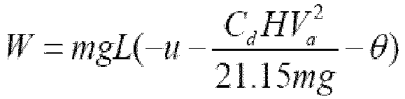
- F win C d HV a 2 21.15 where a represent acceleration.
- p max represents a maximum pressure of a hydraulic system
- p n represents a current pressure of the hydraulic accumulator
- p 1 represents a minimum operating pressure of the hydraulic accumulator
- V 1 represents a volume of gas in the hydraulic accumulator under the minimum pressure
- n represents a polytropic index of the gas.
- the recoverable energy W is greater than the energy S that can be stored in the current remaining space of the hydraulic accumulator, then it is necessary to further control the hydraulic accumulator to release energy to obtain enough energy storage space.
- the electronic horizon system is used in energy management of the hydraulic hybrid vehicle, a power controller of the hydraulic hybrid vehicle is connected to the electronic horizon system, the terrain ahead of the vehicle is obtained from the electronic horizon system, the energy recovery ahead is predicted according to the terrain ahead, and predictive control in advance is performed on the energy release of the hydraulic accumulator.
- the method of this embodiment can ensure to a greater extent the hydraulic accumulator with limited capacity to recover and utilize as much energy as possible, thereby improving the vehicle economy.
- the present invention further provides a power control terminal device for a hydraulic hybrid vehicle, including a memory, a processor, and a computer program stored in the memory and capable of running in the processor.
- the processor when executing the computer program, implements the steps in the method embodiment in Embodiment I of the present invention.
- the power control terminal device for a hydraulic hybrid vehicle may be an on-board computer, a cloud server or other computing devices.
- the power control terminal device for a hydraulic hybrid vehicle may include, but not limited to, a processor and a memory. It can be understood by those skilled in the art that the composition of the power control terminal device for a hydraulic hybrid vehicle is merely an example of the power control terminal device for a hydraulic hybrid vehicle, and does not constitute a limitation to the power control terminal device for a hydraulic hybrid vehicle.
- the power control terminal device for a hydraulic hybrid vehicle may include more or less components than the above, or a combination of some components, or different components.
- the power control terminal device for a hydraulic hybrid vehicle may further include input-output devices, network access devices, buses, etc., which is not limited by the embodiment of the present invention.
- the processor may be a central processing unit (CPU), other general-purpose processors, a digital signal processor (DSP), an application specific integrated circuit (ASIC), a field-programmable gate array (FPGA) or other programmable logic devices, a discrete gate or transistor logic device, a discrete hardware component, etc.
- the general-purpose processor may be a microprocessor, or the processor may also be any conventional processor, etc.
- the processor is the control center of the power control terminal device for a hydraulic hybrid vehicle, and connects all parts of the entire power control terminal device for a hydraulic hybrid vehicle using various interfaces and lines.
- the memory can be used for storing the computer program and/or module.
- the processor implements various functions of the power control terminal device for a hydraulic hybrid vehicle by running or executing the computer program and/or module stored in the memory and calling the data stored in the memory.
- the memory may mainly include a program storage area and a data storage area.
- the program storage area may store an operating system and application programs required by at least one function.
- the data storage area may store data created according to the use of a mobile phone, etc.
- the memory may include a high-speed random access memory, and may further include a non-volatile memory, such as a hard disk, an internal memory, a plug-in hard disk, a smart media card (SMC), a secure digital (SD) card, a flash card, at least one disk memory device, a flash memory device, or other volatile solid-state memory devices.
- a non-volatile memory such as a hard disk, an internal memory, a plug-in hard disk, a smart media card (SMC), a secure digital (SD) card, a flash card, at least one disk memory device, a flash memory device, or other volatile solid-state memory devices.
- the present invention further provides a computer-readable storage medium having a computer program stored thereon.
- the computer program when executed by a processor, implements the steps in the method in the embodiments of the present invention.
- an integrated module/unit of the power control terminal device for a hydraulic hybrid vehicle is implemented in the form of a software functional unit and sold or used as an independent product, it can be stored in a computer-readable storage medium. Based on such understanding, the implementation of all or part of the processes in the method of the embodiments of the present invention may also be completed by instructing related hardware by the computer program.
- the computer program may be stored in a computer-readable storage medium.
- the computer program when executed by the processor, can implement the steps in the method embodiments.
- the computer program includes a computer program code, which may be in the form of a source code, an object code or an executable file, or in some intermediate forms.
- the computer-readable medium may include: any entity or apparatus capable of carrying the computer program code, a recording medium, a USB flash drive, a removable hard drive, a magnetic disk, an optical disk, a computer memory, a read-only memory (ROM), a random access memory (RAM), a software distribution medium, etc.
Landscapes
- Engineering & Computer Science (AREA)
- Chemical & Material Sciences (AREA)
- Combustion & Propulsion (AREA)
- Mechanical Engineering (AREA)
- Transportation (AREA)
- Automation & Control Theory (AREA)
- Business, Economics & Management (AREA)
- Physics & Mathematics (AREA)
- Strategic Management (AREA)
- Human Resources & Organizations (AREA)
- Economics (AREA)
- Mathematical Physics (AREA)
- Game Theory and Decision Science (AREA)
- Development Economics (AREA)
- Entrepreneurship & Innovation (AREA)
- Marketing (AREA)
- Operations Research (AREA)
- Quality & Reliability (AREA)
- Tourism & Hospitality (AREA)
- General Business, Economics & Management (AREA)
- General Physics & Mathematics (AREA)
- Theoretical Computer Science (AREA)
- General Engineering & Computer Science (AREA)
- Hybrid Electric Vehicles (AREA)
- Electric Propulsion And Braking For Vehicles (AREA)
Abstract
Description
- The present invention relates to the field of vehicle control, and in particular to a power control method and terminal device for a hydraulic hybrid vehicle, and a storage medium.
- A power system of a hydraulic hybrid vehicle (HHV) includes an engine and a hydraulic accumulator. The hydraulic accumulator has high power density, high energy storage and release speed and high energy recovery efficiency, and is suitable for frequent storage and release of energy. Therefore, compared with electric hybrid technology, hydraulic hybrid technology is more competitive in mid-size and heavy vehicles and construction machinery. However, the energy density of the hydraulic accumulator is much lower than that of the battery. If the hydraulic accumulator is used to store more energy, this will require a very large size of the hydraulic accumulator. As a result, the hydraulic accumulator of the hydraulic hybrid vehicle usually stores limited energy. In order to achieve higher economy of the hydraulic hybrid vehicle, it is necessary to make full use of limited energy storage space of the hydraulic accumulator, recover vehicle braking or coasting energy as much as possible and use the recovered energy as efficiently as possible.
- Energy management strategies of both parallel and series hydraulic hybrid vehicles are real-time control strategies in which power output or energy recovery of the engine and the hydraulic accumulator are distributed according to the power demand of the vehicle, and there is no predictive control of energy output distribution based on the geographical environment and operating conditions ahead.
- In order to solve the above problems, the present invention provides a power control method and terminal device for a hydraulic hybrid vehicle, and a storage medium.
- The specific solutions are as follows:
Provided is a power control method and terminal device for a hydraulic hybrid vehicle, including the following steps: - S1: predicting, according to environmental information of a road ahead, recoverable energy in the road ahead;
- S2: calculating, according to the predicted recoverable energy, a critical pressure required by a hydraulic accumulator to recover the recoverable energy; and
- S3: determining whether a current pressure of the hydraulic accumulator is greater than the critical pressure, and if so, reducing fuel output power of an engine and controlling the hydraulic accumulator to release energy such that the current pressure of the hydraulic accumulator is less than or equal to the critical pressure.
- Further, the environmental information of the road ahead is obtained from electronic horizon data.
- Further, a specific process of predicting the recoverable energy in the road ahead includes the following steps:
- S101: finding in real time whether there is a downhill section in the road ahead of a current position of the vehicle according to the electronic horizon data, and if so, proceeding to S102; and
- S102: acquiring a gradient θ and a slope length L of the downhill section closest to the current position of the vehicle according to the electronic horizon data, determining whether the gradient θ is greater than a gradient threshold θ 1, and if so, calculating the recoverable energy W in the road ahead according to the following formula:
- A calculation formula of the gradient threshold θ 1 is:

- Further, a calculation formula of the critical pressure required by the hydraulic accumulator to recover the recoverable energy is:

- Provided is a power control terminal device for a hydraulic hybrid vehicle, including a processor, a memory, and a computer program stored in the memory and running in the processor. The processor, when executing the computer program, implements the steps in the method in the embodiments of the present invention.
- Provided is a computer-readable storage medium having a computer program stored thereon. The computer program, when executed by a processor, implements the steps in the method in the embodiments of the present invention.
- According to the above technical solutions of the present invention, when it is predicted that there is a high probability of energy recovery ahead, the energy stored in the hydraulic accumulator is used up in advance, so that the hydraulic accumulator has enough space to recover energy when the energy recovery occurs in future. This can make full use of the characteristic of the hydraulic accumulator of being suitable for frequent storage and release of energy, thereby achieving the economy of energy consumption of the whole vehicle.
-
FIG. 1 shows a flowchart of Embodiment I of the present invention. - To further illustrate the embodiments, the accompanying drawings are provided in the present invention. These accompanying drawings are a part of the contents disclosed in the present invention that are mainly used to illustrate the embodiments, and can be used in conjunction with the related descriptions in the specification to explain the operation principle of the embodiments. With reference to these contents, those skilled in the art will be able to understand other possible implementations and advantages of the present invention.
- The present invention will be further described in conjunction with the accompanying drawings and the specific implementations.
- This embodiment of the present invention provides a power control method for a hydraulic hybrid vehicle. As shown in
FIG. 1 , the method includes the following steps: - S1: Predict, according to environmental information of a road ahead, recoverable energy W in the road ahead.
- In this embodiment, the environmental information of the road ahead is obtained from electronic horizon data.
- The electronic horizon is a technique used for vehicles to predict information of the road ahead, which searches for accurate information of the road ahead of the current position of the vehicle according to map data and satellite positioning signals such that the vehicle has the ability to predict road conditions within a certain distance ahead. The electronic horizon data includes various types of road and traffic information, such as gradients, curves, traffic signs, etc. The information in the electronic horizon used in this embodiment includes gradient information, curve information, speed limit information, and other terrain and road information closely related to changes in power demands of the vehicle.
- A specific method for predicting the recoverable energy W includes:
- S101: Find in real time whether there is a downhill section in the road ahead of a current position of the vehicle according to the electronic horizon data, and if so, proceed to S102.
- S102: Acquire a gradient θ and a slope length L of the downhill section closest to the current position of the vehicle according to the electronic horizon data, determine whether the gradient θ of the downhill section closest to the current position of the vehicle is greater than a gradient threshold θ 1, and if so, which indicates that the gradient θ is enough for the vehicle to coast at the current speed, calculate the recoverable energy W in the road ahead according to the following formula:

- The derivation process of the above calculation formula of the recoverable energy W is described below.
- Since the engine does not output power when the vehicle is in the coasting state, at this time, the kinetic equation of the vehicle in the running process is:

- There are also:


- Therefore, formula (1) may be written as:

- Since the vehicle is running at a constant speed, ma=0; and since the vehicle is in the coasting state, F=0. Therefore, in the coasting state, formula (2) can be transformed into:

- That is, when the gradient θ of the downhill section is


- S2: Calculate, according to the predicted recoverable energy W, a critical pressure required by a hydraulic accumulator to recover the recoverable energy W.
- A calculation formula of energy S that can be stored in the current remaining space of the hydraulic accumulator is:

- If the recoverable energy W is greater than the energy S that can be stored in the current remaining space of the hydraulic accumulator, then it is necessary to further control the hydraulic accumulator to release energy to obtain enough energy storage space.
- The energy S that can be stored in the current remaining space of the hydraulic accumulator is made equal to the recoverable energy W, and the critical pressure Pc required by the hydraulic accumulator to recover the recoverable energy W is calculated as:


- S3: Determine whether a current pressure pn of the hydraulic accumulator is greater than the critical pressure Pc , and if so, reduce fuel output power of an engine and control the hydraulic accumulator to release energy such that the current pressure pn of the hydraulic accumulator is less than or equal to the critical pressure Pc .
- In Embodiment I of the present invention, the electronic horizon system is used in energy management of the hydraulic hybrid vehicle, a power controller of the hydraulic hybrid vehicle is connected to the electronic horizon system, the terrain ahead of the vehicle is obtained from the electronic horizon system, the energy recovery ahead is predicted according to the terrain ahead, and predictive control in advance is performed on the energy release of the hydraulic accumulator. The method of this embodiment can ensure to a greater extent the hydraulic accumulator with limited capacity to recover and utilize as much energy as possible, thereby improving the vehicle economy.
- The present invention further provides a power control terminal device for a hydraulic hybrid vehicle, including a memory, a processor, and a computer program stored in the memory and capable of running in the processor. The processor, when executing the computer program, implements the steps in the method embodiment in Embodiment I of the present invention.
- Further, as a feasible implementation, the power control terminal device for a hydraulic hybrid vehicle may be an on-board computer, a cloud server or other computing devices. The power control terminal device for a hydraulic hybrid vehicle may include, but not limited to, a processor and a memory. It can be understood by those skilled in the art that the composition of the power control terminal device for a hydraulic hybrid vehicle is merely an example of the power control terminal device for a hydraulic hybrid vehicle, and does not constitute a limitation to the power control terminal device for a hydraulic hybrid vehicle. The power control terminal device for a hydraulic hybrid vehicle may include more or less components than the above, or a combination of some components, or different components. For example, the power control terminal device for a hydraulic hybrid vehicle may further include input-output devices, network access devices, buses, etc., which is not limited by the embodiment of the present invention.
- Further, as a feasible implementation, the processor may be a central processing unit (CPU), other general-purpose processors, a digital signal processor (DSP), an application specific integrated circuit (ASIC), a field-programmable gate array (FPGA) or other programmable logic devices, a discrete gate or transistor logic device, a discrete hardware component, etc. The general-purpose processor may be a microprocessor, or the processor may also be any conventional processor, etc. The processor is the control center of the power control terminal device for a hydraulic hybrid vehicle, and connects all parts of the entire power control terminal device for a hydraulic hybrid vehicle using various interfaces and lines.
- The memory can be used for storing the computer program and/or module. The processor implements various functions of the power control terminal device for a hydraulic hybrid vehicle by running or executing the computer program and/or module stored in the memory and calling the data stored in the memory. The memory may mainly include a program storage area and a data storage area. The program storage area may store an operating system and application programs required by at least one function. The data storage area may store data created according to the use of a mobile phone, etc. Besides, the memory may include a high-speed random access memory, and may further include a non-volatile memory, such as a hard disk, an internal memory, a plug-in hard disk, a smart media card (SMC), a secure digital (SD) card, a flash card, at least one disk memory device, a flash memory device, or other volatile solid-state memory devices.
- The present invention further provides a computer-readable storage medium having a computer program stored thereon. The computer program, when executed by a processor, implements the steps in the method in the embodiments of the present invention.
- If an integrated module/unit of the power control terminal device for a hydraulic hybrid vehicle is implemented in the form of a software functional unit and sold or used as an independent product, it can be stored in a computer-readable storage medium. Based on such understanding, the implementation of all or part of the processes in the method of the embodiments of the present invention may also be completed by instructing related hardware by the computer program. The computer program may be stored in a computer-readable storage medium. The computer program, when executed by the processor, can implement the steps in the method embodiments. The computer program includes a computer program code, which may be in the form of a source code, an object code or an executable file, or in some intermediate forms. The computer-readable medium may include: any entity or apparatus capable of carrying the computer program code, a recording medium, a USB flash drive, a removable hard drive, a magnetic disk, an optical disk, a computer memory, a read-only memory (ROM), a random access memory (RAM), a software distribution medium, etc.
- Although the present invention has been specifically shown and described in connection with the preferred implementations, it should be understood by those skilled in the art that various changes in form and details can be made without departing from the spirit and scope of the present invention as defined by the appended claims, and shall all fall within the protection scope of the present invention.
Claims (6)
- A power control method for a hydraulic hybrid vehicle, comprising the following steps:S1: predicting, according to environmental information of a road ahead, recoverable energy in the road ahead;S2: calculating, according to the predicted recoverable energy, a critical pressure required by a hydraulic accumulator to recover the recoverable energy; andS3: determining whether a current pressure of the hydraulic accumulator is greater than the critical pressure, and if so, reducing fuel output power of an engine and controlling the hydraulic accumulator to release energy such that the current pressure of the hydraulic accumulator is less than or equal to the critical pressure.
- The power control method for a hydraulic hybrid vehicle according to claim 1, wherein the environmental information of the road ahead is obtained from electronic horizon data.
- The power control method for a hydraulic hybrid vehicle according to claim 2, wherein a specific process of predicting the recoverable energy in the road ahead comprises the following steps:S101: finding in real time whether there is a downhill section in the road ahead of a current position of the vehicle according to the electronic horizon data, and if so, proceeding to S102; andS102: acquiring a gradient θ and a slope length L of the downhill section closest to the current position of the vehicle according to the electronic horizon data, determining whether the gradient θ is greater than a gradient threshold θ 1, and if so, calculating the recoverable energy W in the road ahead according to the following formula:
 wherein m represents mass, g represents gravity acceleration, µ represents a road friction coefficient, Cd represents air density, H represents a frontal area of the vehicle, and Va represents a windward wind speed of the vehicle; anda calculation formula of the gradient threshold θ 1 is:
- The power control method for a hydraulic hybrid vehicle according to claim 1, wherein a calculation formula of the critical pressure required by the hydraulic accumulator to recover the recoverable energy is:

wherein Pc represents the critical pressure, pmax represents a maximum pressure of a hydraulic system, and p1 represents a minimum operating pressure of the hydraulic accumulator; V1 represents a volume of gas in the hydraulic accumulator under the minimum pressure; and n represents a polytropic index of the gas. - A power control terminal device for a hydraulic hybrid vehicle, comprising a processor, a memory, and a computer program stored in the memory and running in the processor, wherein the processor, when executing the computer program, implements the steps in the method according to any of claims 1 to 4.
- A computer-readable storage medium having a computer program stored thereon, wherein the computer program, when executed by a processor, implements the steps in the method according to any of claims 1 to 4.
Applications Claiming Priority (2)
| Application Number | Priority Date | Filing Date | Title |
|---|---|---|---|
| CN202010678051.5A CN113942517A (en) | 2020-07-15 | 2020-07-15 | Hydraulic hybrid vehicle power control method, terminal device and storage medium |
| PCT/CN2020/109667 WO2022011771A1 (en) | 2020-07-15 | 2020-08-18 | Hydraulic hybrid vehicle power control method, terminal device and storage medium |
Publications (3)
| Publication Number | Publication Date |
|---|---|
| EP4183652A1 true EP4183652A1 (en) | 2023-05-24 |
| EP4183652A4 EP4183652A4 (en) | 2024-10-02 |
| EP4183652B1 EP4183652B1 (en) | 2026-01-28 |
Family
ID=79326262
Family Applications (1)
| Application Number | Title | Priority Date | Filing Date |
|---|---|---|---|
| EP20945378.6A Active EP4183652B1 (en) | 2020-07-15 | 2020-08-18 | Hydraulic hybrid vehicle power control method, terminal device and storage medium |
Country Status (4)
| Country | Link |
|---|---|
| US (1) | US11981332B2 (en) |
| EP (1) | EP4183652B1 (en) |
| CN (1) | CN113942517A (en) |
| WO (1) | WO2022011771A1 (en) |
Families Citing this family (1)
| Publication number | Priority date | Publication date | Assignee | Title |
|---|---|---|---|---|
| CN118928019B (en) * | 2024-07-11 | 2025-11-14 | 中国第一汽车股份有限公司 | Onboard liquid energy recovery system, method, vehicle and storage medium |
Family Cites Families (15)
| Publication number | Priority date | Publication date | Assignee | Title |
|---|---|---|---|---|
| US5887674A (en) * | 1995-10-11 | 1999-03-30 | The United States Of America As Represented By The Administrator Of The U.S. Environmental Protection Agency | Continuously smooth transmission |
| CN1927632A (en) * | 2006-05-23 | 2007-03-14 | 上海交大神舟汽车设计开发有限公司 | Hydraulic mixed power urban bus |
| US20080000381A1 (en) * | 2006-05-24 | 2008-01-03 | Bartley Thomas L | Rail car braking regeneration and propulsion system and method |
| JP2013005485A (en) * | 2011-06-13 | 2013-01-07 | Nissan Motor Co Ltd | Charge control device of vehicle battery |
| CN104284823B (en) * | 2012-05-08 | 2017-06-20 | 沃尔沃拉斯特瓦格纳公司 | EMS and saving of fuel method for hybrid electric vehicle |
| CN104973057A (en) * | 2014-04-03 | 2015-10-14 | 李治良 | Intelligent prediction control system |
| FR3028236B1 (en) * | 2014-11-07 | 2016-12-16 | Valeo Systemes De Controle Moteur | ENGINE CONTROL SYSTEM |
| KR101655609B1 (en) * | 2014-12-11 | 2016-09-07 | 현대자동차주식회사 | Method for controlling battery state of charge in hybrid electric vehicle |
| US10654465B2 (en) * | 2015-07-02 | 2020-05-19 | Volvo Truck Corporation | Method for controlling a hydraulic hybrid vehicle |
| JP6347235B2 (en) * | 2015-07-30 | 2018-06-27 | トヨタ自動車株式会社 | Control device for hybrid vehicle |
| JP2017081475A (en) * | 2015-10-30 | 2017-05-18 | トヨタ自動車株式会社 | Vehicle control apparatus |
| JP6372532B2 (en) * | 2016-09-05 | 2018-08-15 | トヨタ自動車株式会社 | Electric vehicle and control method of electric vehicle |
| CN107747948B (en) * | 2017-09-25 | 2021-09-17 | 北京信息科技大学 | Vehicle-mounted composite power supply control system and method for electric vehicle |
| US11117475B2 (en) * | 2018-10-22 | 2021-09-14 | Woven Planet North America, Inc. | Systems and methods for efficient vehicle control |
| KR102545107B1 (en) * | 2018-12-03 | 2023-06-20 | 현대자동차주식회사 | Eco-friendly vehicle and method of hill descent control for the same |
-
2020
- 2020-07-15 CN CN202010678051.5A patent/CN113942517A/en active Pending
- 2020-08-18 WO PCT/CN2020/109667 patent/WO2022011771A1/en not_active Ceased
- 2020-08-18 US US18/005,631 patent/US11981332B2/en active Active
- 2020-08-18 EP EP20945378.6A patent/EP4183652B1/en active Active
Also Published As
| Publication number | Publication date |
|---|---|
| US20230286511A1 (en) | 2023-09-14 |
| EP4183652B1 (en) | 2026-01-28 |
| EP4183652A4 (en) | 2024-10-02 |
| US11981332B2 (en) | 2024-05-14 |
| WO2022011771A1 (en) | 2022-01-20 |
| CN113942517A (en) | 2022-01-18 |
Similar Documents
| Publication | Publication Date | Title |
|---|---|---|
| CN108216198B (en) | Enhanced engine and battery operation | |
| US8428812B2 (en) | Travel trace generation method and travel trace generation device | |
| US9446773B2 (en) | System and method for assisting driver | |
| KR102821561B1 (en) | Energy recovery method and device, electric vehicle, and storage medium | |
| US20150061550A1 (en) | Method for electrically regenerating an energy store | |
| Van Keulen et al. | Predictive cruise control in hybrid electric vehicles | |
| US10946852B2 (en) | Systems and methods for determining engine start time during predicted acceleration events | |
| US12420661B2 (en) | Energy management method and terminal device for electric vehicle, and storage medium | |
| CN110936947A (en) | Control method, device, equipment and medium for hybrid electric vehicle | |
| US12179606B1 (en) | Method and apparatus for managing power battery of a vehicle, storage medium and electronic device | |
| EP4147935B1 (en) | Method for calculating mass of vehicle, and terminal device and storage medium | |
| US11927266B2 (en) | Dual-speed final drive control method and terminal device, and storage medium | |
| EP4253137A1 (en) | Curve prediction-based electric vehicle energy management method, terminal device, and storage medium | |
| EP4257440A1 (en) | Vehicle-following distance control method based on terrain, and terminal device and storage medium | |
| EP4183652B1 (en) | Hydraulic hybrid vehicle power control method, terminal device and storage medium | |
| US20250137811A1 (en) | Drivable surface and lane group estimation | |
| CN118372808A (en) | Method and device for controlling range extender of range extender automobile based on driving style of driver | |
| JP2015113075A (en) | Control apparatus of hybrid vehicle | |
| CN115370737A (en) | Vehicle gear prediction control method, terminal device and storage medium | |
| US20250137809A1 (en) | Drivable surface and lane group estimation | |
| CN115701502A (en) | Gearbox control method based on terrain prediction, terminal device and storage medium | |
| CN114258457B (en) | Delay cylinder reactivation | |
| CN117261623A (en) | Range extender control method and device, electronic equipment and storage medium | |
| Mohammadi et al. | A comparison of fixed and dynamic regenerative braking low-speed boundary on eco-driving of autonomous electric vehicles | |
| EP4180646B1 (en) | Predictive egr control method, terminal device, and storage medium |
Legal Events
| Date | Code | Title | Description |
|---|---|---|---|
| STAA | Information on the status of an ep patent application or granted ep patent |
Free format text: STATUS: THE INTERNATIONAL PUBLICATION HAS BEEN MADE |
|
| PUAI | Public reference made under article 153(3) epc to a published international application that has entered the european phase |
Free format text: ORIGINAL CODE: 0009012 |
|
| STAA | Information on the status of an ep patent application or granted ep patent |
Free format text: STATUS: REQUEST FOR EXAMINATION WAS MADE |
|
| 17P | Request for examination filed |
Effective date: 20230215 |
|
| AK | Designated contracting states |
Kind code of ref document: A1 Designated state(s): AL AT BE BG CH CY CZ DE DK EE ES FI FR GB GR HR HU IE IS IT LI LT LU LV MC MK MT NL NO PL PT RO RS SE SI SK SM TR |
|
| DAV | Request for validation of the european patent (deleted) | ||
| DAX | Request for extension of the european patent (deleted) | ||
| RAP3 | Party data changed (applicant data changed or rights of an application transferred) |
Owner name: XIAMEN YAXON ZHILIAN TECHNOLOGY CO., LTD. |
|
| A4 | Supplementary search report drawn up and despatched |
Effective date: 20240903 |
|
| RIC1 | Information provided on ipc code assigned before grant |
Ipc: G06Q 10/04 20230101ALI20240828BHEP Ipc: B60W 50/00 20060101ALI20240828BHEP Ipc: B60W 30/18 20120101ALI20240828BHEP Ipc: B60W 20/12 20160101ALI20240828BHEP Ipc: B60W 10/24 20060101ALI20240828BHEP Ipc: B60W 10/06 20060101ALI20240828BHEP Ipc: B60W 10/04 20060101ALI20240828BHEP Ipc: B60K 6/12 20060101ALI20240828BHEP Ipc: B60W 20/14 20160101ALI20240828BHEP Ipc: B60W 20/13 20160101ALI20240828BHEP Ipc: B60W 40/076 20120101AFI20240828BHEP |
|
| GRAP | Despatch of communication of intention to grant a patent |
Free format text: ORIGINAL CODE: EPIDOSNIGR1 |
|
| STAA | Information on the status of an ep patent application or granted ep patent |
Free format text: STATUS: GRANT OF PATENT IS INTENDED |
|
| INTG | Intention to grant announced |
Effective date: 20250811 |
|
| GRAS | Grant fee paid |
Free format text: ORIGINAL CODE: EPIDOSNIGR3 |
|
| GRAA | (expected) grant |
Free format text: ORIGINAL CODE: 0009210 |
|
| STAA | Information on the status of an ep patent application or granted ep patent |
Free format text: STATUS: THE PATENT HAS BEEN GRANTED |
|
| AK | Designated contracting states |
Kind code of ref document: B1 Designated state(s): AL AT BE BG CH CY CZ DE DK EE ES FI FR GB GR HR HU IE IS IT LI LT LU LV MC MK MT NL NO PL PT RO RS SE SI SK SM TR |
|
| REG | Reference to a national code |
Ref country code: CH Ref legal event code: F10 Free format text: ST27 STATUS EVENT CODE: U-0-0-F10-F00 (AS PROVIDED BY THE NATIONAL OFFICE) Effective date: 20260128 Ref country code: GB Ref legal event code: FG4D |
|
| REG | Reference to a national code |
Ref country code: DE Ref legal event code: R096 Ref document number: 602020066407 Country of ref document: DE |
|
| REG | Reference to a national code |
Ref country code: IE Ref legal event code: FG4D |
|
| U01 | Request for unitary effect filed |
Effective date: 20260302 |