EP4183633A1 - Profile of a crossbar, especially for mounting to roof rails on vehicles - Google Patents
Profile of a crossbar, especially for mounting to roof rails on vehicles Download PDFInfo
- Publication number
- EP4183633A1 EP4183633A1 EP22020548.8A EP22020548A EP4183633A1 EP 4183633 A1 EP4183633 A1 EP 4183633A1 EP 22020548 A EP22020548 A EP 22020548A EP 4183633 A1 EP4183633 A1 EP 4183633A1
- Authority
- EP
- European Patent Office
- Prior art keywords
- sub
- profile
- tear
- circle
- determining
- Prior art date
- Legal status (The legal status is an assumption and is not a legal conclusion. Google has not performed a legal analysis and makes no representation as to the accuracy of the status listed.)
- Granted
Links
Images
Classifications
-
- B—PERFORMING OPERATIONS; TRANSPORTING
- B60—VEHICLES IN GENERAL
- B60R—VEHICLES, VEHICLE FITTINGS, OR VEHICLE PARTS, NOT OTHERWISE PROVIDED FOR
- B60R9/00—Supplementary fittings on vehicle exterior for carrying loads, e.g. luggage, sports gear or the like
- B60R9/04—Carriers associated with vehicle roof
- B60R9/05—Carriers characterised by wind deflecting means
-
- B—PERFORMING OPERATIONS; TRANSPORTING
- B60—VEHICLES IN GENERAL
- B60R—VEHICLES, VEHICLE FITTINGS, OR VEHICLE PARTS, NOT OTHERWISE PROVIDED FOR
- B60R9/00—Supplementary fittings on vehicle exterior for carrying loads, e.g. luggage, sports gear or the like
- B60R9/04—Carriers associated with vehicle roof
- B60R9/052—Carriers comprising elongate members extending only transversely of vehicle
Definitions
- the present invention relates to the outer shape of the profile of a crossbar carrier, especially for mounting to roof rails on vehicles, designed for fitting luggage for vehicles such as cars or boats.
- the outer shape can also be advantageously used for fitting the flaps of antennas, radars on boats and cars.
- Roof rack luggage carriers usually consist of two crossbars arranged across the vehicle roof. Each crossbar is fitted with a foot which holds the crossbar in position above the roof. The foot is usually attached to the crossbar carrier on one end and is typically attached to the vehicle at the other end. The foot is also referred to in some publications as a side support foot, as for example in patent file CZ 280424 B6 . This foot is most often attached to the roof rail using holding clamps; another option is attachment to the roof rail or directly to the roof using bolts.
- the carrier crossbars are usually designed as extruded aluminium profiles.
- the outer shape of the profile varies.
- Simple embodiments have the shape of a square with rounded corners or a rectangle with rounded corners. More complex shapes are designed for better airflow than the simple shapes, and therefore have the shape of a wing or a similar aerodynamic shape.
- the shape of some crossbars is also intended to improve the downforce on the vehicle, such as what is described, for example, in file DE 10012905 A1 .
- Roof rack profiles usually have a slot at the top for T-shape clamping bolts which are used to secure the load on the carrier.
- Patent file DE 10012905 A1 deals with airflow around the carrier itself.
- the carrier crossbar cross-section has slots for the insertion of turbulators, made in the form of elastic shaped parts, which after insertion into the profile protrude above the carrier crossbar outer shape.
- the turbulators are inserted into the profile in a direction perpendicular to the direction of the travel, i.e. in the direction of the profile axis.
- the upper turbulator is designed to disturb the flow around the clamping bolt T-slot, and thus prevent the hum that this slot produces if not covered or otherwise treated.
- There is also a turbulator on the underside which controls the diffusion of the lower and upper airflow behind the thickest part of the profile.
- the patent mentioned above further seeks to achieve downforce by means of the appropriate shape and position of the turbulators to increase the vehicle's driving stability.
- File WO 9954168 A1 deals with the airflow over the clamping bolt T-slot, by inserting a flexible compressible member into the slot, aiming to achieve a better transition of the bypassing airflow from the part of the outer shape in front of the slot to the surface of the flexible member covering the slot, and then the transition to the outer shape behind the slot.
- the beam itself has a generally profiled cross-section with an upward and downward projection on its front side in the direction of travel. When used, the projections in the leading edge create a turbulent flow with sufficient energy to cause the airflow to move away from the bypassed shape, thus achieving a smooth transition in the area where the flexible member inside the slot connects to the surrounding beam profile.
- Patent file EP 2 570 304 B1 correctly represents the above general background, and further deals with the connection of the carrier crossbar to the foot of the carrier. In particular, it deals with the solution of connecting the crossbar profile to the foot, in order to save as much space as possible. Furthermore, common designs of crossbars are known, which have a square or rectangular profile in the cross section, see patent files DE 3516483 A1 , DE 3104163 A1 , or a circular profile, see patent file DE 3510805 A1 . These designs do not significantly address the aerodynamic characteristics and the associated airflow. This results in various adverse noise effects when used at higher driving speeds.
- the object of the present invention is to reduce the noise manifestation in the vehicle resulting from the air bypass at its strong positive incidence angle, at the point of the airflow compaction from the vehicle nose, while taking into account the simultaneous interaction of the outgoing airflow with the vehicle roof. This is achieved both by diverting the laminar flow away from the bottom of the profile along its entire depth/length, over a wide range of airflow velocities, which prevents the air mass between the crossbar and the roof from oscillating leading to low frequency noise, and by creating a turbulent drift behind the profile trailing edge. This condition prevents the oscillation of the air mass with high frequency noise manifestation.
- the described profile can be used without any problems at the point of the densest airflow or the point where the airflow from the whole front part of the vehicle is directed.
- the present invention deals with the suppression of noise manifestations which arise in particular in the area of the front roof rack of the vehicle due to the strong positive incidence direction while the vehicle is moving, and the subsequent interaction with the roof and its immediate surroundings.
- the difference from the previous inventions is in particular in the solution that deals with the case where there is a strong positive incidence angle of the airflow, and the solution of the associated more complex issue, as it solves the air bypass around the carrier and at the same time around the roof under the carrier.
- a solution based on the profile of the crossbar carrier in particular for mounting to the roof rails of vehicles, consisting of a formed solid body, the outer profile of which has a rounded front part and a trailing part at the rear end, with a flat leading part running diagonally downwards in the bottom area of the front part, followed by a rounded tear-off projection terminating along its entire length by a tear-off edge, which is located in an area defined by the first interval of 0.31p s to 0.73p s measured perpendicularly from the determining line a and the second interval of 0,75p k to 0.98p k , where the determining line a is the line between the furthest point B of the front part and the furthest point A of the trailing part of the body, p s is the first determining parameter, based on the diameter of the third circle k 3 inscribed at the point of the greatest width of the encircled cross-sectional profile of the body, and p k is the second
- the leading surface is inclined from determining line a at an angle of 65° to 85°, i.e. angle ⁇ of the inclination of the leading surface to tangent c leading through point B perpendicular to determining line a is within the angular range of 5° to 25°.
- the present invention achieves new and higher effect by precisely dimensional embodiment and positioning of the tear-off edge projection in the lower area of the full width of the leading part of the outer profile, to suppress the noise manifestation of the flowing air mass by suppressing its oscillation over the entire crossbar carrier profile width, while the air flow interacts with the roof of the vehicle.
- a crossbar roof rack for mounting to the roof rails of vehicles, in particular cars comprises a shaped solid body 1 with an outer profile with a rounded front part 2, i.e. a front designed for the flow of air while the car is moving, and a trailing part 3 in the end rear part, where a diagonally sloping planar leading surface 21 is formed in the bottom area of the front part 2, followed by a rounded tear-off projection 22 terminating with a tear-off edge 221 along its entire length.
- the actual location of the tear-off projection 22 and its tear-off edge 221 is based on the results of long-term research supported by many experiments, when the diameter of the first circle k 1 of the inscribed outflow part 3 was chosen as the basic parameters of the cross-section of the proposed profile, the diameter of the second circle k 2 over the outermost point B of the front part 2 and the outermost point A of the trailing part 3 of the body 1 connected by the determining line a, the diameter of the third circle k 3 inscribed at the point of the greatest width of the bypassed cross-sectional profile of the body 1 and the angle of inclination ⁇ of the leading surface 21 to the tangent c drawn by the point B perpendicular to the determining line a.
- the first determining parameter p s is based on the diameter of the third circle k 3 and the second determining parameter p k is given by the diameter of the second circle k 2 , as can be seen in Fig. 4 .
- the tear-off edge 221 of the tear-off projection 22 is located in an area defined by the first interval of between 0.31 p s and 0.73 p s measured perpendicularly from the determining line a and the second interval of between 0.75 p k and 0,98 p k measured between auxiliary circles k 4 and k 5 , concentric with the second circle k 2 .
- the leading surface 21 is inclined from determining line a at an angle of 65° to 85°, i.e. angle ⁇ of the inclination of the leading surface 21 to tangent c is within the angular range of 5° to 25°.
- the functional crossbar carrier had the following parameters:
- the present invention is applicable especially for the design of the profile of a crossbar carrier, designed for mounting to roof rails on vehicles, designed for fitting luggage for vehicles such as cars or boats.
- the outer shape can also be advantageously used for fitting the flaps of antennas, radars on boats and cars.
Landscapes
- Engineering & Computer Science (AREA)
- Mechanical Engineering (AREA)
- Fittings On The Vehicle Exterior For Carrying Loads, And Devices For Holding Or Mounting Articles (AREA)
- Hybrid Cells (AREA)
- Photovoltaic Devices (AREA)
Abstract
Description
- The present invention relates to the outer shape of the profile of a crossbar carrier, especially for mounting to roof rails on vehicles, designed for fitting luggage for vehicles such as cars or boats. The outer shape can also be advantageously used for fitting the flaps of antennas, radars on boats and cars.
- Roof rack luggage carriers usually consist of two crossbars arranged across the vehicle roof. Each crossbar is fitted with a foot which holds the crossbar in position above the roof. The foot is usually attached to the crossbar carrier on one end and is typically attached to the vehicle at the other end. The foot is also referred to in some publications as a side support foot, as for example in patent file
CZ 280424 B6 - The carrier crossbars are usually designed as extruded aluminium profiles. The outer shape of the profile varies. Simple embodiments have the shape of a square with rounded corners or a rectangle with rounded corners. More complex shapes are designed for better airflow than the simple shapes, and therefore have the shape of a wing or a similar aerodynamic shape. The shape of some crossbars is also intended to improve the downforce on the vehicle, such as what is described, for example, in file
DE 10012905 A1 . - Roof rack profiles usually have a slot at the top for T-shape clamping bolts which are used to secure the load on the carrier.
- Patent file
DE 10012905 A1 deals with airflow around the carrier itself. The carrier crossbar cross-section has slots for the insertion of turbulators, made in the form of elastic shaped parts, which after insertion into the profile protrude above the carrier crossbar outer shape. The turbulators are inserted into the profile in a direction perpendicular to the direction of the travel, i.e. in the direction of the profile axis. The upper turbulator is designed to disturb the flow around the clamping bolt T-slot, and thus prevent the hum that this slot produces if not covered or otherwise treated. There is also a turbulator on the underside which controls the diffusion of the lower and upper airflow behind the thickest part of the profile. The patent mentioned above further seeks to achieve downforce by means of the appropriate shape and position of the turbulators to increase the vehicle's driving stability. - File
WO 9954168 A1 -
Patent file EP 2 570 304 B1 correctly represents the above general background, and further deals with the connection of the carrier crossbar to the foot of the carrier. In particular, it deals with the solution of connecting the crossbar profile to the foot, in order to save as much space as possible. Furthermore, common designs of crossbars are known, which have a square or rectangular profile in the cross section, see patent filesDE 3516483 A1 ,DE 3104163 A1 , or a circular profile, see patent fileDE 3510805 A1 . These designs do not significantly address the aerodynamic characteristics and the associated airflow. This results in various adverse noise effects when used at higher driving speeds. - The object of the present invention is to reduce the noise manifestation in the vehicle resulting from the air bypass at its strong positive incidence angle, at the point of the airflow compaction from the vehicle nose, while taking into account the simultaneous interaction of the outgoing airflow with the vehicle roof. This is achieved both by diverting the laminar flow away from the bottom of the profile along its entire depth/length, over a wide range of airflow velocities, which prevents the air mass between the crossbar and the roof from oscillating leading to low frequency noise, and by creating a turbulent drift behind the profile trailing edge. This condition prevents the oscillation of the air mass with high frequency noise manifestation. The described profile can be used without any problems at the point of the densest airflow or the point where the airflow from the whole front part of the vehicle is directed.
- Thus, the present invention deals with the suppression of noise manifestations which arise in particular in the area of the front roof rack of the vehicle due to the strong positive incidence direction while the vehicle is moving, and the subsequent interaction with the roof and its immediate surroundings. Thus, the difference from the previous inventions is in particular in the solution that deals with the case where there is a strong positive incidence angle of the airflow, and the solution of the associated more complex issue, as it solves the air bypass around the carrier and at the same time around the roof under the carrier.
- The stated objective is achieved by a solution based on the profile of the crossbar carrier, in particular for mounting to the roof rails of vehicles, consisting of a formed solid body, the outer profile of which has a rounded front part and a trailing part at the rear end, with a flat leading part running diagonally downwards in the bottom area of the front part, followed by a rounded tear-off projection terminating along its entire length by a tear-off edge, which is located in an area defined by the first interval of 0.31ps to 0.73ps measured perpendicularly from the determining line a and the second interval of 0,75pk to 0.98pk, where the determining line a is the line between the furthest point B of the front part and the furthest point A of the trailing part of the body, p s is the first determining parameter, based on the diameter of the third circle k3 inscribed at the point of the greatest width of the encircled cross-sectional profile of the body, and pk is the second determining parameter, based on the diameter of the second circle k 2 corresponding to the linear distance between points A and B.
- In a preferred embodiment, the leading surface is inclined from determining line a at an angle of 65° to 85°, i.e. angle α of the inclination of the leading surface to tangent c leading through point B perpendicular to determining line a is within the angular range of 5° to 25°.
- In an optimal embodiment, the tear-off edge of the tear-off projection is sharp or is formed with a minimum radius r within the range of r = 0.1 × (p s + p k )/2.
- The present invention achieves new and higher effect by precisely dimensional embodiment and positioning of the tear-off edge projection in the lower area of the full width of the leading part of the outer profile, to suppress the noise manifestation of the flowing air mass by suppressing its oscillation over the entire crossbar carrier profile width, while the air flow interacts with the roof of the vehicle.
- Specific examples of the invention embodiments are shown in the accompanying drawings where:
-
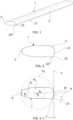
Fig. 1 is the overall axonometric view of the crossbar carrier, -
Fig. 2 is a vertical cross-section through the crossbar carrier profile fromFig. 1 , perpendicular to its longitudinal axis, without showing the design parameters, -
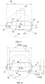
Fig.3 is a vertical cross-section of the crossbar carrier profile fromFig. 2 , showing the basic design parameters, -
Fig. 4 is a vertical cross-section of the crossbar carrier profile fromFig. 2 , showing parameters pK and pS, -
Fig. 5 is a vertical cross-section of the crossbar carrier profile fromFig. 2 , showing the parameters of the tear-off edge location using four dimensions, -
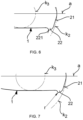
Fig. 6 is a detail of the basic embodiment of the tear-off projection ended with a sharp tear-off edge, and -
Fig. 7 is a detail of an alternative embodiment of the tear-off projection with a rounded tear-off edge. - The drawings illustrating the presented invention and the following examples of particular embodiments do not in any way limit the scope of protection stipulated in the definition, but merely illustrate the principle of the invention.
- A crossbar roof rack for mounting to the roof rails of vehicles, in particular cars, comprises a shaped
solid body 1 with an outer profile with arounded front part 2, i.e. a front designed for the flow of air while the car is moving, and atrailing part 3 in the end rear part, where a diagonally sloping planar leadingsurface 21 is formed in the bottom area of thefront part 2, followed by a rounded tear-offprojection 22 terminating with a tear-offedge 221 along its entire length. - The actual location of the tear-off
projection 22 and its tear-offedge 221 is based on the results of long-term research supported by many experiments, when the diameter of the first circle k 1 of the inscribedoutflow part 3 was chosen as the basic parameters of the cross-section of the proposed profile, the diameter of the second circle k 2 over the outermost point B of thefront part 2 and the outermost point A of thetrailing part 3 of thebody 1 connected by the determining line a, the diameter of the third circle k 3 inscribed at the point of the greatest width of the bypassed cross-sectional profile of thebody 1 and the angle of inclination α of the leadingsurface 21 to the tangent c drawn by the point B perpendicular to the determining line a. The first determining parameter p s is based on the diameter of the third circle k 3 and the second determining parameter p k is given by the diameter of the second circle k 2 , as can be seen inFig. 4 . - As shown in
fig. 5 , the tear-offedge 221 of the tear-offprojection 22 is located in an area defined by the first interval of between 0.31p s and 0.73p s measured perpendicularly from the determining line a and the second interval of between 0.75 p k and 0,98p k measured between auxiliary circles k 4 and k 5 , concentric with the second circle k 2 . The leadingsurface 21 is inclined from determining line a at an angle of 65° to 85°, i.e. angle α of the inclination of the leadingsurface 21 to tangent c is within the angular range of 5° to 25°. - The tear-off
edge 221 as a technical term describing the part of the profile bypassed by air where the airflow is separated from the crossbar carrier should ideally be formed by a sharp connection of two surfaces, i.e. it should ideally be an edge. With respect to the manufacturing capabilities, such a condition can never be achieved, and instead of an edge, there is typically a minimum rounding at this area, which can have a maximum radius of r within the range of r = 0.1 × (p s + p k )/2 to maintain due functionality, as shown inFig. 7 . - In a specific and verified case, the functional crossbar carrier had the following parameters:
- the first determining parameter p s (diameter of the third circle k 3 ) of 29.4mm
- perpendicular distance of the tear-off
edge 221 from the determining line a of 15.7mm - the second determining parameter p k (diameter of the third circle k 2 ) of 80mm
- diameter of auxiliary circles of 72mm
- radius of the curvature of the roundness of the tear-
off projection 22 with the size of 5mm - angle of inclination of the leading
surface 21 from the determining line a of 73.28° - radius r of the roundness of the tear-
off edge 221 of 1.8mm. - The present invention is applicable especially for the design of the profile of a crossbar carrier, designed for mounting to roof rails on vehicles, designed for fitting luggage for vehicles such as cars or boats. The outer shape can also be advantageously used for fitting the flaps of antennas, radars on boats and cars.
-
- 1 ... body
- 2 ... front part
- 21 .. leading surface
- 22 .. tear-off projection
- 221 . tear-off edge
- 3 ... trailing part
- k1 ... first circle
- k2 ... second circle
- k3 ... third circle
- k4 ... fourth circle, i.e. circle with centre at S2 and a diameter of 0.75 times the diameter of circle k2
- k5 ... fifth circle, i.e. circle with centre at S2 and a diameter of 0.98 times the diameter of circle k2
- S1 ... centre of the first circle
- S2 ... centre of the second circle
- S3 ... centre of the third circle
- a ... determining line passing through end points A and B of the body
- c ... tangent line leading through point B perpendicular to determining line a
- α ... angle of inclination of the leading
surface 21 to tangent c - ps... the first determining parameter, based on the diameter of the third circle k3.
- pk ... the second determining parameter, based on the direct distance between points A and B.
Claims (3)
- Profile of the crossbar carrier, in particular for mounting to the roof rails of vehicles, consisting of a formed solid body, the outer profile of which has a rounded front part and a trailing part at the rear end, characterized in that the bottom area of the front part (2) has a flat leading surface (21) running diagonally downwards, followed by a rounded tear-off projection (22) terminating along its entire length by a tear-off edge (221), which is located in an area defined by the first interval of 0.31ps to 0.73ps measured perpendicularly from the determining line (a) and the second interval of 0,75pk to 0.98pk, where the determining line (a) is the line between the furthest point (B) of the front part (2) and the furthest point (A) of the outflow part (3) of the body (1), (ps) is the first determining parameter, based on the diameter of the third circle (k3) inscribed at the point of the greatest width of the encircled cross-sectional profile of the body (1), and (pk) is the second determining parameter, based on the diameter of the second circle (k2) corresponding to the linear distance between points (A) and (B).
- The profile of the crossbar carrier according to claim 1, characterized in that the leading surface (21) is inclined from determining line (a) at an angle of 65° to 85°, i.e. angle (α) of the inclination of the leading surface (21) to tangent (c) leading through point (B) perpendicular to determining line (a) is within the angular range of 5° to 25°.
- The profile of the crossbar carrier according to claim 1, characterized in that the tear-off edge (221) of the tear-off projection (22) is sharp or is formed with a minimum radius (r) within the range of r = 0.1 × ( p s + p k )/2.
Applications Claiming Priority (1)
| Application Number | Priority Date | Filing Date | Title |
|---|---|---|---|
| CZ2021-528A CZ2021528A3 (en) | 2021-11-23 | 2021-11-23 | Transverse carrier profile, especially for attachment to longitudinal roof carriers of vehicles |
Publications (2)
| Publication Number | Publication Date |
|---|---|
| EP4183633A1 true EP4183633A1 (en) | 2023-05-24 |
| EP4183633B1 EP4183633B1 (en) | 2024-02-14 |
Family
ID=84104955
Family Applications (1)
| Application Number | Title | Priority Date | Filing Date |
|---|---|---|---|
| EP22020548.8A Active EP4183633B1 (en) | 2021-11-23 | 2022-11-11 | Profile of a crossbar, especially for mounting to roof rails on vehicles |
Country Status (3)
| Country | Link |
|---|---|
| EP (1) | EP4183633B1 (en) |
| CZ (1) | CZ2021528A3 (en) |
| PL (1) | PL4183633T3 (en) |
Citations (8)
| Publication number | Priority date | Publication date | Assignee | Title |
|---|---|---|---|---|
| DE3104163A1 (en) | 1981-02-06 | 1982-09-02 | Heinrich Wunder GmbH & Co KG, 8060 Dachau | Roof rack for motor vehicles having a roof rail |
| DE3510805A1 (en) | 1985-03-25 | 1986-10-02 | Gebr. Haslbeck GmbH, 8260 Mühldorf | Clamping device for roof rack systems |
| DE3516483A1 (en) | 1985-05-08 | 1986-11-13 | Daimler-Benz Ag, 7000 Stuttgart | Cross-strut for roof racks of motor vehicles having a roof rail |
| WO1992012874A1 (en) * | 1991-01-16 | 1992-08-06 | Goodcart Pty Limited | Vehicle roof rack |
| CZ280424B6 (en) | 1991-03-13 | 1996-01-17 | Votex Gmbh | Transverse section of a vehicle roof-associated carrier transverse beam |
| WO1999054168A1 (en) | 1998-04-22 | 1999-10-28 | Hubco Industries Limited | Roof rack or load carrier |
| DE10012905A1 (en) | 2000-03-16 | 2001-09-20 | Anton Lechner | Roof rack for vehicle has streamlined device extending along transverse member |
| EP2570304B1 (en) | 2011-09-16 | 2017-06-14 | Thule Sweden AB | A load carrier foot for a vehicle roof rack |
-
2021
- 2021-11-23 CZ CZ2021-528A patent/CZ2021528A3/en unknown
-
2022
- 2022-11-11 EP EP22020548.8A patent/EP4183633B1/en active Active
- 2022-11-11 PL PL22020548.8T patent/PL4183633T3/en unknown
Patent Citations (8)
| Publication number | Priority date | Publication date | Assignee | Title |
|---|---|---|---|---|
| DE3104163A1 (en) | 1981-02-06 | 1982-09-02 | Heinrich Wunder GmbH & Co KG, 8060 Dachau | Roof rack for motor vehicles having a roof rail |
| DE3510805A1 (en) | 1985-03-25 | 1986-10-02 | Gebr. Haslbeck GmbH, 8260 Mühldorf | Clamping device for roof rack systems |
| DE3516483A1 (en) | 1985-05-08 | 1986-11-13 | Daimler-Benz Ag, 7000 Stuttgart | Cross-strut for roof racks of motor vehicles having a roof rail |
| WO1992012874A1 (en) * | 1991-01-16 | 1992-08-06 | Goodcart Pty Limited | Vehicle roof rack |
| CZ280424B6 (en) | 1991-03-13 | 1996-01-17 | Votex Gmbh | Transverse section of a vehicle roof-associated carrier transverse beam |
| WO1999054168A1 (en) | 1998-04-22 | 1999-10-28 | Hubco Industries Limited | Roof rack or load carrier |
| DE10012905A1 (en) | 2000-03-16 | 2001-09-20 | Anton Lechner | Roof rack for vehicle has streamlined device extending along transverse member |
| EP2570304B1 (en) | 2011-09-16 | 2017-06-14 | Thule Sweden AB | A load carrier foot for a vehicle roof rack |
Also Published As
| Publication number | Publication date |
|---|---|
| PL4183633T3 (en) | 2024-06-10 |
| EP4183633B1 (en) | 2024-02-14 |
| CZ309402B6 (en) | 2022-11-23 |
| CZ2021528A3 (en) | 2022-11-23 |
Similar Documents
| Publication | Publication Date | Title |
|---|---|---|
| US9682735B2 (en) | Fuel efficiency of road vehicles | |
| US4022508A (en) | Air drag reducing means for bluff vehicles and the like | |
| US7497502B2 (en) | Mini skirt aerodynamic fairing device for reducing the aerodynamic drag of ground vehicles | |
| US7740303B2 (en) | Mini skirt aerodynamic fairing device for reducing the aerodynamic drag of ground vehicles | |
| US6702364B2 (en) | Method and apparatus for reducing drag on a vehicle in motion and channeling air flow to form a bug shield | |
| US4360232A (en) | Aerodynamic drag reduction apparatus for vehicles or the like | |
| US10189516B1 (en) | Vehicle aerodynamic assemblies for providing passive water management | |
| CN102307776A (en) | air guide | |
| US5294033A (en) | Cross-sectional configuration of a roof luggage carrier of a vehicle | |
| US9010842B2 (en) | Aerodynamic drag and noise reduction device for a vehicle roof rack article carrier | |
| US6116365A (en) | Arrangement for ventilating an assembly on a vehicle | |
| EP4183633A1 (en) | Profile of a crossbar, especially for mounting to roof rails on vehicles | |
| US20160288632A1 (en) | Vehicle sunroof wind deflector | |
| GB2538156A (en) | Improvements in the fuel efficiency of road vehicles | |
| CN208498414U (en) | An engine room flow tank NVH device combination and engine room flow tank connecting bracket | |
| US4047747A (en) | Air drag reducer for motor freight vehicles | |
| CN110027631A (en) | Air-deflector and motor vehicle body for motor vehicle body | |
| GB2063799A (en) | Drag reducing devices for road vehicles | |
| US12110066B1 (en) | Laterally wind-diverting vehicle fairing | |
| EP0044746A1 (en) | Nose fairing assembly | |
| US6086140A (en) | Light bar air deflector | |
| JP6060879B2 (en) | Rear spoiler structure for vehicles | |
| JP6531619B2 (en) | Rear spoiler | |
| RU2013273C1 (en) | Fairing | |
| KR20020044491A (en) | Roof rack carrier for an automobile |
Legal Events
| Date | Code | Title | Description |
|---|---|---|---|
| PUAI | Public reference made under article 153(3) epc to a published international application that has entered the european phase |
Free format text: ORIGINAL CODE: 0009012 |
|
| STAA | Information on the status of an ep patent application or granted ep patent |
Free format text: STATUS: REQUEST FOR EXAMINATION WAS MADE |
|
| 17P | Request for examination filed |
Effective date: 20221125 |
|
| AK | Designated contracting states |
Kind code of ref document: A1 Designated state(s): AL AT BE BG CH CY CZ DE DK EE ES FI FR GB GR HR HU IE IS IT LI LT LU LV MC ME MK MT NL NO PL PT RO RS SE SI SK SM TR |
|
| RIC1 | Information provided on ipc code assigned before grant |
Ipc: B60R 9/052 20060101ALI20230718BHEP Ipc: B60R 9/05 20060101AFI20230718BHEP |
|
| GRAP | Despatch of communication of intention to grant a patent |
Free format text: ORIGINAL CODE: EPIDOSNIGR1 |
|
| STAA | Information on the status of an ep patent application or granted ep patent |
Free format text: STATUS: GRANT OF PATENT IS INTENDED |
|
| INTG | Intention to grant announced |
Effective date: 20230913 |
|
| GRAS | Grant fee paid |
Free format text: ORIGINAL CODE: EPIDOSNIGR3 |
|
| GRAA | (expected) grant |
Free format text: ORIGINAL CODE: 0009210 |
|
| STAA | Information on the status of an ep patent application or granted ep patent |
Free format text: STATUS: THE PATENT HAS BEEN GRANTED |
|
| AK | Designated contracting states |
Kind code of ref document: B1 Designated state(s): AL AT BE BG CH CY CZ DE DK EE ES FI FR GB GR HR HU IE IS IT LI LT LU LV MC ME MK MT NL NO PL PT RO RS SE SI SK SM TR |
|
| REG | Reference to a national code |
Ref country code: GB Ref legal event code: FG4D |
|
| REG | Reference to a national code |
Ref country code: CH Ref legal event code: EP |
|
| REG | Reference to a national code |
Ref country code: DE Ref legal event code: R096 Ref document number: 602022001880 Country of ref document: DE |
|
| REG | Reference to a national code |
Ref country code: IE Ref legal event code: FG4D |
|
| REG | Reference to a national code |
Ref country code: SK Ref legal event code: T3 Ref document number: E 43910 Country of ref document: SK |
|
| REG | Reference to a national code |
Ref country code: LT Ref legal event code: MG9D |
|
| REG | Reference to a national code |
Ref country code: NL Ref legal event code: MP Effective date: 20240214 |
|
| PG25 | Lapsed in a contracting state [announced via postgrant information from national office to epo] |
Ref country code: IS Free format text: LAPSE BECAUSE OF FAILURE TO SUBMIT A TRANSLATION OF THE DESCRIPTION OR TO PAY THE FEE WITHIN THE PRESCRIBED TIME-LIMIT Effective date: 20240614 |
|
| PG25 | Lapsed in a contracting state [announced via postgrant information from national office to epo] |
Ref country code: LT Free format text: LAPSE BECAUSE OF FAILURE TO SUBMIT A TRANSLATION OF THE DESCRIPTION OR TO PAY THE FEE WITHIN THE PRESCRIBED TIME-LIMIT Effective date: 20240214 |
|
| PG25 | Lapsed in a contracting state [announced via postgrant information from national office to epo] |
Ref country code: GR Free format text: LAPSE BECAUSE OF FAILURE TO SUBMIT A TRANSLATION OF THE DESCRIPTION OR TO PAY THE FEE WITHIN THE PRESCRIBED TIME-LIMIT Effective date: 20240515 |
|
| REG | Reference to a national code |
Ref country code: AT Ref legal event code: MK05 Ref document number: 1656789 Country of ref document: AT Kind code of ref document: T Effective date: 20240214 |
|
| PG25 | Lapsed in a contracting state [announced via postgrant information from national office to epo] |
Ref country code: HR Free format text: LAPSE BECAUSE OF FAILURE TO SUBMIT A TRANSLATION OF THE DESCRIPTION OR TO PAY THE FEE WITHIN THE PRESCRIBED TIME-LIMIT Effective date: 20240214 Ref country code: NL Free format text: LAPSE BECAUSE OF FAILURE TO SUBMIT A TRANSLATION OF THE DESCRIPTION OR TO PAY THE FEE WITHIN THE PRESCRIBED TIME-LIMIT Effective date: 20240214 Ref country code: RS Free format text: LAPSE BECAUSE OF FAILURE TO SUBMIT A TRANSLATION OF THE DESCRIPTION OR TO PAY THE FEE WITHIN THE PRESCRIBED TIME-LIMIT Effective date: 20240514 |
|
| PG25 | Lapsed in a contracting state [announced via postgrant information from national office to epo] |
Ref country code: ES Free format text: LAPSE BECAUSE OF FAILURE TO SUBMIT A TRANSLATION OF THE DESCRIPTION OR TO PAY THE FEE WITHIN THE PRESCRIBED TIME-LIMIT Effective date: 20240214 |
|
| PG25 | Lapsed in a contracting state [announced via postgrant information from national office to epo] |
Ref country code: AT Free format text: LAPSE BECAUSE OF FAILURE TO SUBMIT A TRANSLATION OF THE DESCRIPTION OR TO PAY THE FEE WITHIN THE PRESCRIBED TIME-LIMIT Effective date: 20240214 |
|
| PG25 | Lapsed in a contracting state [announced via postgrant information from national office to epo] |
Ref country code: RS Free format text: LAPSE BECAUSE OF FAILURE TO SUBMIT A TRANSLATION OF THE DESCRIPTION OR TO PAY THE FEE WITHIN THE PRESCRIBED TIME-LIMIT Effective date: 20240514 Ref country code: NO Free format text: LAPSE BECAUSE OF FAILURE TO SUBMIT A TRANSLATION OF THE DESCRIPTION OR TO PAY THE FEE WITHIN THE PRESCRIBED TIME-LIMIT Effective date: 20240514 Ref country code: NL Free format text: LAPSE BECAUSE OF FAILURE TO SUBMIT A TRANSLATION OF THE DESCRIPTION OR TO PAY THE FEE WITHIN THE PRESCRIBED TIME-LIMIT Effective date: 20240214 Ref country code: LT Free format text: LAPSE BECAUSE OF FAILURE TO SUBMIT A TRANSLATION OF THE DESCRIPTION OR TO PAY THE FEE WITHIN THE PRESCRIBED TIME-LIMIT Effective date: 20240214 Ref country code: IS Free format text: LAPSE BECAUSE OF FAILURE TO SUBMIT A TRANSLATION OF THE DESCRIPTION OR TO PAY THE FEE WITHIN THE PRESCRIBED TIME-LIMIT Effective date: 20240614 Ref country code: HR Free format text: LAPSE BECAUSE OF FAILURE TO SUBMIT A TRANSLATION OF THE DESCRIPTION OR TO PAY THE FEE WITHIN THE PRESCRIBED TIME-LIMIT Effective date: 20240214 Ref country code: GR Free format text: LAPSE BECAUSE OF FAILURE TO SUBMIT A TRANSLATION OF THE DESCRIPTION OR TO PAY THE FEE WITHIN THE PRESCRIBED TIME-LIMIT Effective date: 20240515 Ref country code: FI Free format text: LAPSE BECAUSE OF FAILURE TO SUBMIT A TRANSLATION OF THE DESCRIPTION OR TO PAY THE FEE WITHIN THE PRESCRIBED TIME-LIMIT Effective date: 20240214 Ref country code: ES Free format text: LAPSE BECAUSE OF FAILURE TO SUBMIT A TRANSLATION OF THE DESCRIPTION OR TO PAY THE FEE WITHIN THE PRESCRIBED TIME-LIMIT Effective date: 20240214 Ref country code: BG Free format text: LAPSE BECAUSE OF FAILURE TO SUBMIT A TRANSLATION OF THE DESCRIPTION OR TO PAY THE FEE WITHIN THE PRESCRIBED TIME-LIMIT Effective date: 20240214 Ref country code: AT Free format text: LAPSE BECAUSE OF FAILURE TO SUBMIT A TRANSLATION OF THE DESCRIPTION OR TO PAY THE FEE WITHIN THE PRESCRIBED TIME-LIMIT Effective date: 20240214 |
|
| PG25 | Lapsed in a contracting state [announced via postgrant information from national office to epo] |
Ref country code: PT Free format text: LAPSE BECAUSE OF FAILURE TO SUBMIT A TRANSLATION OF THE DESCRIPTION OR TO PAY THE FEE WITHIN THE PRESCRIBED TIME-LIMIT Effective date: 20240614 |
|
| PG25 | Lapsed in a contracting state [announced via postgrant information from national office to epo] |
Ref country code: SE Free format text: LAPSE BECAUSE OF FAILURE TO SUBMIT A TRANSLATION OF THE DESCRIPTION OR TO PAY THE FEE WITHIN THE PRESCRIBED TIME-LIMIT Effective date: 20240214 Ref country code: PT Free format text: LAPSE BECAUSE OF FAILURE TO SUBMIT A TRANSLATION OF THE DESCRIPTION OR TO PAY THE FEE WITHIN THE PRESCRIBED TIME-LIMIT Effective date: 20240614 Ref country code: LV Free format text: LAPSE BECAUSE OF FAILURE TO SUBMIT A TRANSLATION OF THE DESCRIPTION OR TO PAY THE FEE WITHIN THE PRESCRIBED TIME-LIMIT Effective date: 20240214 |
|
| PG25 | Lapsed in a contracting state [announced via postgrant information from national office to epo] |
Ref country code: DK Free format text: LAPSE BECAUSE OF FAILURE TO SUBMIT A TRANSLATION OF THE DESCRIPTION OR TO PAY THE FEE WITHIN THE PRESCRIBED TIME-LIMIT Effective date: 20240214 |
|
| PG25 | Lapsed in a contracting state [announced via postgrant information from national office to epo] |
Ref country code: SM Free format text: LAPSE BECAUSE OF FAILURE TO SUBMIT A TRANSLATION OF THE DESCRIPTION OR TO PAY THE FEE WITHIN THE PRESCRIBED TIME-LIMIT Effective date: 20240214 |
|
| PG25 | Lapsed in a contracting state [announced via postgrant information from national office to epo] |
Ref country code: EE Free format text: LAPSE BECAUSE OF FAILURE TO SUBMIT A TRANSLATION OF THE DESCRIPTION OR TO PAY THE FEE WITHIN THE PRESCRIBED TIME-LIMIT Effective date: 20240214 Ref country code: CZ Free format text: LAPSE BECAUSE OF FAILURE TO SUBMIT A TRANSLATION OF THE DESCRIPTION OR TO PAY THE FEE WITHIN THE PRESCRIBED TIME-LIMIT Effective date: 20240214 |
|
| PG25 | Lapsed in a contracting state [announced via postgrant information from national office to epo] |
Ref country code: SM Free format text: LAPSE BECAUSE OF FAILURE TO SUBMIT A TRANSLATION OF THE DESCRIPTION OR TO PAY THE FEE WITHIN THE PRESCRIBED TIME-LIMIT Effective date: 20240214 Ref country code: RO Free format text: LAPSE BECAUSE OF FAILURE TO SUBMIT A TRANSLATION OF THE DESCRIPTION OR TO PAY THE FEE WITHIN THE PRESCRIBED TIME-LIMIT Effective date: 20240214 Ref country code: EE Free format text: LAPSE BECAUSE OF FAILURE TO SUBMIT A TRANSLATION OF THE DESCRIPTION OR TO PAY THE FEE WITHIN THE PRESCRIBED TIME-LIMIT Effective date: 20240214 Ref country code: DK Free format text: LAPSE BECAUSE OF FAILURE TO SUBMIT A TRANSLATION OF THE DESCRIPTION OR TO PAY THE FEE WITHIN THE PRESCRIBED TIME-LIMIT Effective date: 20240214 Ref country code: CZ Free format text: LAPSE BECAUSE OF FAILURE TO SUBMIT A TRANSLATION OF THE DESCRIPTION OR TO PAY THE FEE WITHIN THE PRESCRIBED TIME-LIMIT Effective date: 20240214 |
|
| REG | Reference to a national code |
Ref country code: DE Ref legal event code: R097 Ref document number: 602022001880 Country of ref document: DE |
|
| PG25 | Lapsed in a contracting state [announced via postgrant information from national office to epo] |
Ref country code: IT Free format text: LAPSE BECAUSE OF FAILURE TO SUBMIT A TRANSLATION OF THE DESCRIPTION OR TO PAY THE FEE WITHIN THE PRESCRIBED TIME-LIMIT Effective date: 20240214 |
|
| PLBE | No opposition filed within time limit |
Free format text: ORIGINAL CODE: 0009261 |
|
| STAA | Information on the status of an ep patent application or granted ep patent |
Free format text: STATUS: NO OPPOSITION FILED WITHIN TIME LIMIT |
|
| PG25 | Lapsed in a contracting state [announced via postgrant information from national office to epo] |
Ref country code: IT Free format text: LAPSE BECAUSE OF FAILURE TO SUBMIT A TRANSLATION OF THE DESCRIPTION OR TO PAY THE FEE WITHIN THE PRESCRIBED TIME-LIMIT Effective date: 20240214 |
|
| 26N | No opposition filed |
Effective date: 20241115 |
|
| PG25 | Lapsed in a contracting state [announced via postgrant information from national office to epo] |
Ref country code: SI Free format text: LAPSE BECAUSE OF FAILURE TO SUBMIT A TRANSLATION OF THE DESCRIPTION OR TO PAY THE FEE WITHIN THE PRESCRIBED TIME-LIMIT Effective date: 20240214 |
|
| PG25 | Lapsed in a contracting state [announced via postgrant information from national office to epo] |
Ref country code: MC Free format text: LAPSE BECAUSE OF FAILURE TO SUBMIT A TRANSLATION OF THE DESCRIPTION OR TO PAY THE FEE WITHIN THE PRESCRIBED TIME-LIMIT Effective date: 20240214 |
|
| PG25 | Lapsed in a contracting state [announced via postgrant information from national office to epo] |
Ref country code: LU Free format text: LAPSE BECAUSE OF NON-PAYMENT OF DUE FEES Effective date: 20241111 |
|
| REG | Reference to a national code |
Ref country code: BE Ref legal event code: MM Effective date: 20241130 |
|
| PGFP | Annual fee paid to national office [announced via postgrant information from national office to epo] |
Ref country code: PL Payment date: 20250909 Year of fee payment: 4 |
|
| PG25 | Lapsed in a contracting state [announced via postgrant information from national office to epo] |
Ref country code: BE Free format text: LAPSE BECAUSE OF NON-PAYMENT OF DUE FEES Effective date: 20241130 |
|
| PG25 | Lapsed in a contracting state [announced via postgrant information from national office to epo] |
Ref country code: FR Free format text: LAPSE BECAUSE OF NON-PAYMENT OF DUE FEES Effective date: 20241130 |
|
| PG25 | Lapsed in a contracting state [announced via postgrant information from national office to epo] |
Ref country code: IE Free format text: LAPSE BECAUSE OF NON-PAYMENT OF DUE FEES Effective date: 20241111 |
|
| PGFP | Annual fee paid to national office [announced via postgrant information from national office to epo] |
Ref country code: SK Payment date: 20250710 Year of fee payment: 4 |
|
| PGFP | Annual fee paid to national office [announced via postgrant information from national office to epo] |
Ref country code: DE Payment date: 20251119 Year of fee payment: 4 |
|
| PG25 | Lapsed in a contracting state [announced via postgrant information from national office to epo] |
Ref country code: HU Free format text: LAPSE BECAUSE OF FAILURE TO SUBMIT A TRANSLATION OF THE DESCRIPTION OR TO PAY THE FEE WITHIN THE PRESCRIBED TIME-LIMIT; INVALID AB INITIO Effective date: 20221111 |
|
| PG25 | Lapsed in a contracting state [announced via postgrant information from national office to epo] |
Ref country code: CY Free format text: LAPSE BECAUSE OF FAILURE TO SUBMIT A TRANSLATION OF THE DESCRIPTION OR TO PAY THE FEE WITHIN THE PRESCRIBED TIME-LIMIT; INVALID AB INITIO Effective date: 20221111 |