EP4183546A1 - Plastic body part with rounded upper edges - Google Patents
Plastic body part with rounded upper edges Download PDFInfo
- Publication number
- EP4183546A1 EP4183546A1 EP21306603.8A EP21306603A EP4183546A1 EP 4183546 A1 EP4183546 A1 EP 4183546A1 EP 21306603 A EP21306603 A EP 21306603A EP 4183546 A1 EP4183546 A1 EP 4183546A1
- Authority
- EP
- European Patent Office
- Prior art keywords
- face
- plastic panel
- flap
- plastic
- body part
- Prior art date
- Legal status (The legal status is an assumption and is not a legal conclusion. Google has not performed a legal analysis and makes no representation as to the accuracy of the status listed.)
- Pending
Links
Images



Classifications
-
- B—PERFORMING OPERATIONS; TRANSPORTING
- B29—WORKING OF PLASTICS; WORKING OF SUBSTANCES IN A PLASTIC STATE IN GENERAL
- B29C—SHAPING OR JOINING OF PLASTICS; SHAPING OF MATERIAL IN A PLASTIC STATE, NOT OTHERWISE PROVIDED FOR; AFTER-TREATMENT OF THE SHAPED PRODUCTS, e.g. REPAIRING
- B29C45/00—Injection moulding, i.e. forcing the required volume of moulding material through a nozzle into a closed mould; Apparatus therefor
- B29C45/0053—Injection moulding, i.e. forcing the required volume of moulding material through a nozzle into a closed mould; Apparatus therefor combined with a final operation, e.g. shaping
- B29C45/0055—Shaping
-
- B—PERFORMING OPERATIONS; TRANSPORTING
- B29—WORKING OF PLASTICS; WORKING OF SUBSTANCES IN A PLASTIC STATE IN GENERAL
- B29C—SHAPING OR JOINING OF PLASTICS; SHAPING OF MATERIAL IN A PLASTIC STATE, NOT OTHERWISE PROVIDED FOR; AFTER-TREATMENT OF THE SHAPED PRODUCTS, e.g. REPAIRING
- B29C45/00—Injection moulding, i.e. forcing the required volume of moulding material through a nozzle into a closed mould; Apparatus therefor
- B29C45/0017—Injection moulding, i.e. forcing the required volume of moulding material through a nozzle into a closed mould; Apparatus therefor moulding interconnected elements which are movable with respect to one another, e.g. chains or hinges
-
- B—PERFORMING OPERATIONS; TRANSPORTING
- B23—MACHINE TOOLS; METAL-WORKING NOT OTHERWISE PROVIDED FOR
- B23K—SOLDERING OR UNSOLDERING; WELDING; CLADDING OR PLATING BY SOLDERING OR WELDING; CUTTING BY APPLYING HEAT LOCALLY, e.g. FLAME CUTTING; WORKING BY LASER BEAM
- B23K26/00—Working by laser beam, e.g. welding, cutting or boring
- B23K26/36—Removing material
- B23K26/38—Removing material by boring or cutting
-
- B—PERFORMING OPERATIONS; TRANSPORTING
- B29—WORKING OF PLASTICS; WORKING OF SUBSTANCES IN A PLASTIC STATE IN GENERAL
- B29C—SHAPING OR JOINING OF PLASTICS; SHAPING OF MATERIAL IN A PLASTIC STATE, NOT OTHERWISE PROVIDED FOR; AFTER-TREATMENT OF THE SHAPED PRODUCTS, e.g. REPAIRING
- B29C45/00—Injection moulding, i.e. forcing the required volume of moulding material through a nozzle into a closed mould; Apparatus therefor
- B29C45/0053—Injection moulding, i.e. forcing the required volume of moulding material through a nozzle into a closed mould; Apparatus therefor combined with a final operation, e.g. shaping
-
- B—PERFORMING OPERATIONS; TRANSPORTING
- B62—LAND VEHICLES FOR TRAVELLING OTHERWISE THAN ON RAILS
- B62D—MOTOR VEHICLES; TRAILERS
- B62D25/00—Superstructure or monocoque structure sub-units; Parts or details thereof not otherwise provided for
- B62D25/24—Superstructure sub-units with access or drainage openings having movable or removable closures; Sealing means therefor
-
- B—PERFORMING OPERATIONS; TRANSPORTING
- B62—LAND VEHICLES FOR TRAVELLING OTHERWISE THAN ON RAILS
- B62D—MOTOR VEHICLES; TRAILERS
- B62D29/00—Superstructures, understructures, or sub-units thereof, characterised by the material thereof
- B62D29/04—Superstructures, understructures, or sub-units thereof, characterised by the material thereof predominantly of synthetic material
- B62D29/043—Superstructures
-
- B—PERFORMING OPERATIONS; TRANSPORTING
- B29—WORKING OF PLASTICS; WORKING OF SUBSTANCES IN A PLASTIC STATE IN GENERAL
- B29C—SHAPING OR JOINING OF PLASTICS; SHAPING OF MATERIAL IN A PLASTIC STATE, NOT OTHERWISE PROVIDED FOR; AFTER-TREATMENT OF THE SHAPED PRODUCTS, e.g. REPAIRING
- B29C45/00—Injection moulding, i.e. forcing the required volume of moulding material through a nozzle into a closed mould; Apparatus therefor
- B29C45/0053—Injection moulding, i.e. forcing the required volume of moulding material through a nozzle into a closed mould; Apparatus therefor combined with a final operation, e.g. shaping
- B29C45/0055—Shaping
- B29C2045/0058—Shaping removing material
-
- B—PERFORMING OPERATIONS; TRANSPORTING
- B29—WORKING OF PLASTICS; WORKING OF SUBSTANCES IN A PLASTIC STATE IN GENERAL
- B29C—SHAPING OR JOINING OF PLASTICS; SHAPING OF MATERIAL IN A PLASTIC STATE, NOT OTHERWISE PROVIDED FOR; AFTER-TREATMENT OF THE SHAPED PRODUCTS, e.g. REPAIRING
- B29C2793/00—Shaping techniques involving a cutting or machining operation
- B29C2793/0027—Cutting off
-
- B—PERFORMING OPERATIONS; TRANSPORTING
- B29—WORKING OF PLASTICS; WORKING OF SUBSTANCES IN A PLASTIC STATE IN GENERAL
- B29C—SHAPING OR JOINING OF PLASTICS; SHAPING OF MATERIAL IN A PLASTIC STATE, NOT OTHERWISE PROVIDED FOR; AFTER-TREATMENT OF THE SHAPED PRODUCTS, e.g. REPAIRING
- B29C2793/00—Shaping techniques involving a cutting or machining operation
- B29C2793/009—Shaping techniques involving a cutting or machining operation after shaping
-
- B—PERFORMING OPERATIONS; TRANSPORTING
- B29—WORKING OF PLASTICS; WORKING OF SUBSTANCES IN A PLASTIC STATE IN GENERAL
- B29L—INDEXING SCHEME ASSOCIATED WITH SUBCLASS B29C, RELATING TO PARTICULAR ARTICLES
- B29L2031/00—Other particular articles
- B29L2031/30—Vehicles, e.g. ships or aircraft, or body parts thereof
- B29L2031/3005—Body finishings
Definitions
- the invention relates to vehicle body part. More precisely, the invention is related to vehicle body parts intended to integrate at least one movable flap covering an opening and the method for producing such body parts.
- flap is meant any type of element that can perform a function of covering an opening of the body part, for example, a movable cover, flap, shutter.
- vehicle body part As an assembly of a molded plastic panel inside which an opening is designed and a molded plastic flap designed to cover the opening.
- Plastic panels and flaps have been generally produced as two separate parts and are very complex to produce in terms of costs, color harmony and gap and flushness management. Indeed, regarding color harmony, the current products do not meet this criterion since it is necessary to use more paint on the portions resulting from the cutting, which generates an unsightly excess of paint visible from the exterior of the vehicle that do not meet the specifications of the car manufacturers and therefore require additional steps of reworking. These additional steps are time-consuming and involve additional costs. It is therefore essential to be free from these additional steps.
- the invention relates to a method for producing a plastic body part for motor vehicles comprising the following steps:
- the method of the invention makes easily and inexpensively possible to realize a plastic body part integrating a flap and a plastic panel both decorated before cutting out the flap from the body panel and without any additional steps of reworking the edges of the first face of the plastic panel and of the first face of the flap.
- decorated “decorating coat” or “decorating step”
- any kind of decoration method of such elements known of the skilled person It can be for example painting, digital printing, tampon printing, hot stamping, in mould labeling, foil application and even texturing by etching or laser.
- the method according to the invention makes possible to preserve the decorating coating (paint or other finish) located on these edges during laser cutting so that it is not necessary to retouch the decorating coating to meet the specifications of the car manufacturers.
- having rounded upper edges of the groove prevents the formation of an unsightly excess of decorating coating (paint or other finish) along the edges delimiting the opening of the first face of plastic panel and the edges of the first face of the flap, when the first face of the plastic panel alone (if the decorating step takes place before laser cutting) or when both the first face of the plastic panel and the first face of the flap (if the decorating step takes place after laser cutting) receives a decorating coat (paint or other finish).
- the rounded upper edges of the groove can define a closed surface, i.e. the groove extend all around the sides of the surface that will be laser cutting , or they can define an open surface, i.e. the groove does not extend all around the sides of said surface which remains linked to the first face of the plastic panel by at least one side.
- the plastic panel is decorated before the step of laser cutting.
- the plastic panel is molded with a projecting portion of the first face of the plastic panel, said projecting portion being comprised in the first face of the flap after laser cutting.
- laser cutting of the plastic panel takes place in a non-vertical cutting plane locally with respect to the first face of the plastic panel.
- the thickness of the projecting portion with respect to the rest of the first face of the plastic panel is about 0.4 mm.
- the invention also relates to a plastic body part for motor vehicles comprising:
- plastic body part taken alone or in combination:
- Figures 1 to 10 show a plastic body part according to an embodiment and a variant, designated by the general reference 1.
- This plastic body part can be made according to a first method for producing or according to a variant of such a method.
- another decoration method can be used instead of or in addition to paint.
- a plastic panel 2 is molded, such a plastic panel 2 having a first face 21 and a second face 22 opposed to the first face 21.
- the plastic panel 2 is molded with a groove 12 having rounded upper edges 13 on the first face 21 and delimiting a surface of the first face 21 which is intended to be the flap 30 after the laser cutting step.
- the delimited surface is an open surface which means that the surface intended to be the flap 30 after the laser cutting step remains linked to the first face 21 of the plastic panel 2 by one of its sides.
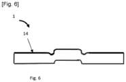
- edges 13 of the flap 30 and edges 13 of the plastic panel 2 delimiting the opening 10 are rounded edges, which is very advantageous for aesthetic reasons, particularly as these edges are easier to cover (with paint 14, as shown on fig. 6 ). It is possible to paint the plastic panel 2 before laser cutting ( fig. 6 ) while maintaining an excellent harmony of paint for the final part 1, particularly on the edges 13 resulting from the laser cutting which meets the specifications of car manufacturers.
- the groove 12 has a circular shape, or a substantially circular shape, which has a diameter h3 equal to or greater than the thickness h2 of the laser cutting.
- the plastic body part 1 comprises:
- the lap 30 is intended to be moved between the closed position and an open position in which the opening 10 is not entirely closed by the flap 30.
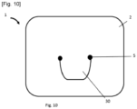
- the plastic body part 1 comprises means 5 ( fig. 10 ) for moving the flap 30 relative to the plastic panel 2 between these two positions.
- Such means 5 are known for the skilled person. It can be for example one or more hinges.
- the plastic panel 2 is molded with a projecting portion 3 of the first face 21, such a projecting portion 3 is sized during the molding step.
- the plastic panel 2 is molded with a recess 4 in the second face 22 opposed to the projecting portion, the recess 4 having a corresponding shape to the shape of the projecting portion 3.
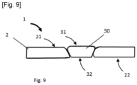
- a recess 4 ensures that the flap will not protrude below the second face of the plastic panel when the flap is in the closed position ( fig. 9 ), which may be preferable in some cases, with regard to the aerodynamic performance of the body part and with regard to final visual appearance requirements of the end-users.
- To have recess 4 having a corresponding shape to the shape of the projecting portion 3 allows to mold a part which has a constant thickness which improves the injection molding quality of the part.
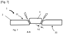
- the laser cutting step of the plastic panel 2 is carried out in a non-vertical cutting plane locally with respect to the first face 21, forming the opening 10 and the flap 30 (composed by the projecting portion 3) (see fig 7 ).
- Cutting the first face 21 the plastic panel 2 according to a locally non-vertical cutting plane ensures optimum flushness between the first side 31 of the flap 30 and the first side 21 of the plastic panel 2 when the flap 30 is in the closed position, i.e. both first faces, respectively of the flap 31 and of the plastic panel 21, are in the same plane in the area of the cut (the faces could be slightly curved away from the area of the cut).
- Such a flush quality is otherwise not possible with a vertical cutting plane.
- a very good flush quality was observed for a cutting plane forming an angle between 40° and 60° with respect to the first side 21 of the plastic panel 2.
- a very good flush quality has also been observed when the thickness h1 of the projecting portion is about 0.4 mm, since this particularly small value corresponds to one of the smallest thicknesses achievable by known laser cutting device.
- the thickness can be around at least 1.5 mm.
- it can be use two or more laser cuttings devices in parallel or a single laser cutting device that is repeated, each time parallel to the previous laser cutting.
Landscapes
- Engineering & Computer Science (AREA)
- Mechanical Engineering (AREA)
- Manufacturing & Machinery (AREA)
- Chemical & Material Sciences (AREA)
- Combustion & Propulsion (AREA)
- Transportation (AREA)
- Physics & Mathematics (AREA)
- Optics & Photonics (AREA)
- Plasma & Fusion (AREA)
- Architecture (AREA)
- Structural Engineering (AREA)
- Laser Beam Processing (AREA)
Abstract
Description
- The invention relates to vehicle body part. More precisely, the invention is related to vehicle body parts intended to integrate at least one movable flap covering an opening and the method for producing such body parts. By "flap" is meant any type of element that can perform a function of covering an opening of the body part, for example, a movable cover, flap, shutter.
- It is known to produce vehicle body part as an assembly of a molded plastic panel inside which an opening is designed and a molded plastic flap designed to cover the opening.
- Plastic panels and flaps have been generally produced as two separate parts and are very complex to produce in terms of costs, color harmony and gap and flushness management. Indeed, regarding color harmony, the current products do not meet this criterion since it is necessary to use more paint on the portions resulting from the cutting, which generates an unsightly excess of paint visible from the exterior of the vehicle that do not meet the specifications of the car manufacturers and therefore require additional steps of reworking. These additional steps are time-consuming and involve additional costs. It is therefore essential to be free from these additional steps.
- In an attempt to overcome this problem, it is known to mold a plastic panel into which the flap is cut out and to paint the plastic panel before cutting out the flap. However, even this solution requires repainting the edges of the plastic panel and the flap, as the paint that covered these portions is usually damaged during the laser cutting process.
- The invention relates to a method for producing a plastic body part for motor vehicles comprising the following steps:
- molding of a plastic panel having a first face and a second face opposed to the first face, the plastic panel comprising a groove having rounded upper edges on the first face and delimiting a surface of the first face,
- laser cutting of the plastic panel at the bottom of the groove while preserving the rounded profile of said upper edges, forming an opening and a flap intended to cover the opening in a closed position.
- So, the method of the invention makes easily and inexpensively possible to realize a plastic body part integrating a flap and a plastic panel both decorated before cutting out the flap from the body panel and without any additional steps of reworking the edges of the first face of the plastic panel and of the first face of the flap. By "decorated", "decorating coat" or "decorating step", it is understood any kind of decoration method of such elements known of the skilled person. It can be for example painting, digital printing, tampon printing, hot stamping, in mould labeling, foil application and even texturing by etching or laser.
- In other words, the method according to the invention makes possible to preserve the decorating coating (paint or other finish) located on these edges during laser cutting so that it is not necessary to retouch the decorating coating to meet the specifications of the car manufacturers. Indeed, having rounded upper edges of the groove prevents the formation of an unsightly excess of decorating coating (paint or other finish) along the edges delimiting the opening of the first face of plastic panel and the edges of the first face of the flap, when the first face of the plastic panel alone (if the decorating step takes place before laser cutting) or when both the first face of the plastic panel and the first face of the flap (if the decorating step takes place after laser cutting) receives a decorating coat (paint or other finish).
- By "delimiting a surface of this first face", it is understood that the rounded upper edges of the groove can define a closed surface, i.e. the groove extend all around the sides of the surface that will be laser cutting , or they can define an open surface, i.e. the groove does not extend all around the sides of said surface which remains linked to the first face of the plastic panel by at least one side.
- In order to save time and space, especially on the production line, the plastic panel is decorated before the step of laser cutting.
- In order to optimize the flush arrangement between the first face of the flap and the first face of the plastic panel when the flap is in the closed position, the plastic panel is molded with a projecting portion of the first face of the plastic panel, said projecting portion being comprised in the first face of the flap after laser cutting. Still with the aim of optimizing the flushness, laser cutting of the plastic panel takes place in a non-vertical cutting plane locally with respect to the first face of the plastic panel. More advantageously, the thickness h2 of the laser cutting is defined by the following formula:

- The invention also relates to a plastic body part for motor vehicles comprising:
- a plastic panel having an opening, a first face and a second face opposed to the first face and
- a flap cut out from the plastic panel and having a first face and a second face opposed to the first face of the flap, the flap being suitable for closing the panel opening when the flap is positioned in a closed position,
- Following, other optional features of plastic body part taken alone or in combination:
- the first face of the flap and the first face of the plastic panel are covered with the same coating, preferably said coating being a paint, before the flap is cut out from the plastic panel,
- the first face of flap is flush with the first face of the plastic panel in the closed position,
- the plastic body part comprising means for moving the flap relative to the plastic panel between the closed position and an open position in which the opening is not entirely closed by the flap.
- The invention will be better understood on reading the following description, which is given only by way of example and is made with reference to the annexed drawings in which:
- [
Fig. 1] figure 1 is a top view of a molded plastic panel according to a first embodiment of the invention; - [
Fig. 2] figure 2 is a cross-sectional view showing the plastic panel in section AA ofFigure 1 ; - [
Fig. 3] figure 3 is a cross-sectional view showing laser cutting of the plastic panel offigure 2 ; - [
Fig. 4] figure 4 is a cross-sectional view showing a plastic body part according to the first embodiment of the invention; - [
Fig. 5] figure 5 is a cross-sectional view showing a plastic panel according to a variant of the first embodiment of the invention; - [
Fig. 6] figure 6 is a cross-sectional view showing a painted plastic panel according to said variant; - [
Fig. 7] figure 7 is a cross-sectional view showing laser cutting of the plastic panel offigure 5 ; - [
Fig. 8] figure 8 is a cross-sectional view showing a plastic body part according to said variant; - [
Fig. 9] figure 9 is a cross-sectional view showing a plastic body part offigure 8 in a closed position of the flap; - [
Fig. 10] figure 10 is a top view of a plastic body part of the invention with moving means. -
Figures 1 to 10 show a plastic body part according to an embodiment and a variant, designated by thegeneral reference 1. This plastic body part can be made according to a first method for producing or according to a variant of such a method. For the following description, we will use painting as the decoration method used for the method of producing and the plastic body part according to the invention. Of course, as mentioned before, another decoration method can be used instead of or in addition to paint. - First, a
plastic panel 2 is molded, such aplastic panel 2 having afirst face 21 and asecond face 22 opposed to thefirst face 21. Theplastic panel 2 is molded with agroove 12 having roundedupper edges 13 on thefirst face 21 and delimiting a surface of thefirst face 21 which is intended to be theflap 30 after the laser cutting step. In the illustrated embodiment and variant, the delimited surface is an open surface which means that the surface intended to be theflap 30 after the laser cutting step remains linked to thefirst face 21 of theplastic panel 2 by one of its sides. - Then, the laser cutting step of the
plastic panel 2 is carried out at the bottom of thegroove 12 in order to form theflap 30 and theopening 10 while preserving the rounded profile of saidupper edges 13. In other words,edges 13 of theflap 30 andedges 13 of theplastic panel 2 delimiting theopening 10 are rounded edges, which is very advantageous for aesthetic reasons, particularly as these edges are easier to cover (withpaint 14, as shown onfig. 6 ). It is possible to paint theplastic panel 2 before laser cutting (fig. 6 ) while maintaining an excellent harmony of paint for thefinal part 1, particularly on theedges 13 resulting from the laser cutting which meets the specifications of car manufacturers. It is therefore possible to dispense from all the subsequent steps of reworking that are generally necessary, either to repaint a portion damaged during cutting or to remove excess paint from these edges. This saves time and space on the production line since theplastic panel 2 and theflap 30 can be painted simultaneously without the need for subsequent operations. Furthermore, this allows a perfect color match when theflap 30 and theplastic panel 2 are painted together. Even if theflap 30 and theplastic panel 2 are painted after laser cutting, which may be the case if, for example, they are to be covered with two different coatings, this still saves time and space on the production line since subsequent rework can be avoided. To preserve the rounded profile of saidupper edges 13 it is advantageous that thegroove 12 has a circular shape, or a substantially circular shape, which has a diameter h3 equal to or greater than the thickness h2 of the laser cutting. - In its final version (
fig. 4 and8-9 ), theplastic body part 1 comprises: - a
plastic panel 2 having anopening 10, afirst face 21 and asecond face 22 opposed to thefirst face 21 and - a
flap 30 cut out from theplastic panel 2 and having afirst face 31 and asecond face 32 opposed to thefirst face 31 of theflap 30, theflap 30 being suitable for closing the panel opening 10 when theflap 30 is positioned in a closed position (seefig. 4 and9 ), theedges 13 of thefirst face 21 of theplastic panel 2 delimiting theopening 10 and the edges of thefirst face 31 of theflap 30 arerounded edges 13. - For aerodynamics and/or ventilation reasons, the
lap 30 is intended to be moved between the closed position and an open position in which theopening 10 is not entirely closed by theflap 30. To do so, theplastic body part 1 comprises means 5 (fig. 10 ) for moving theflap 30 relative to theplastic panel 2 between these two positions. Such means 5 are known for the skilled person. It can be for example one or more hinges. - According to a variant of the method of the invention (
figs 5 to 9 ), theplastic panel 2 is molded with a projectingportion 3 of thefirst face 21, such a projectingportion 3 is sized during the molding step. By sizing the thickness h1 of the projectingportion 3 and knowing the angle α of the non-vertical cutting plane with respect to thefirst face 21, it is possible to define the thickness h2 of the laser cutting to be made for the next step, thanks to the following formula:
first face 31 ofcut flap 30 completely flush with thefirst face 21 of theplastic panel 2, when theflap 30 is positioned in a closed position of the panel opening 10 (fig.9 ), without any additional costs for separate injection or cutting tools. Advantageously, theplastic panel 2 is molded with a recess 4 in thesecond face 22 opposed to the projecting portion, the recess 4 having a corresponding shape to the shape of the projectingportion 3. Such a recess 4 ensures that the flap will not protrude below the second face of the plastic panel when the flap is in the closed position (fig. 9 ), which may be preferable in some cases, with regard to the aerodynamic performance of the body part and with regard to final visual appearance requirements of the end-users. To have recess 4 having a corresponding shape to the shape of the projectingportion 3 allows to mold a part which has a constant thickness which improves the injection molding quality of the part. - In such a variant of the method of the invention, the laser cutting step of the
plastic panel 2 is carried out in a non-vertical cutting plane locally with respect to thefirst face 21, forming theopening 10 and the flap 30 (composed by the projecting portion 3) (seefig 7 ). Cutting thefirst face 21 theplastic panel 2 according to a locally non-vertical cutting plane ensures optimum flushness between thefirst side 31 of theflap 30 and thefirst side 21 of theplastic panel 2 when theflap 30 is in the closed position, i.e. both first faces, respectively of theflap 31 and of theplastic panel 21, are in the same plane in the area of the cut (the faces could be slightly curved away from the area of the cut). Such a flush quality is otherwise not possible with a vertical cutting plane. A very good flush quality was observed for a cutting plane forming an angle between 40° and 60° with respect to thefirst side 21 of theplastic panel 2. A very good flush quality has also been observed when the thickness h1 of the projecting portion is about 0.4 mm, since this particularly small value corresponds to one of the smallest thicknesses achievable by known laser cutting device. - So, it is easily possible to make, without any additional costs for separate injection or cutting tools or without any additional reworking or repainting steps, a plastic body part completely flush when the
flap 30 is positioned in a closed position of thepanel opening 10 and which has an excellent harmony of paint. - Alternatively, it may be necessary to have thicknesses greater than 0.4mm in some cases (e.g. when the flap contour is been illuminated from the back for design reasons). In such cases, the thickness can be around at least 1.5 mm. To achieve such a thickness it can be use two or more laser cuttings devices in parallel or a single laser cutting device that is repeated, each time parallel to the previous laser cutting.
- The invention is not limited to the embodiments shown and other embodiments will be apparent to the skilled person.
-
- 1: plastic body part
- 2: plastic panel
- 3: projecting portion
- 4: recess
- 5: means for moving the flap relative to the plastic panel
- 6: /
- 7: /
- 8: /
- 9: /
- 10: opening
- 11: /
- 12: groove
- 13: rounded upper edges
- 14: paint
- 15: /
- 16: /
- 17: /
- 18: /
- 19: /
- 20: /
- 21: first face of the plastic panel
- 22: second face of the plastic panel
- 23: /
- 24: /
- 25: /
- 26: /
- 27: /
- 28: /
- 29: /
- 30: flap
- 31: first face of the flap
- 32: second face of the flap
- h1: thickness of the projecting portion
- h2: thickness of the laser cutting
Claims (10)
- Method for producing a plastic body part (1) for motor vehicles comprising the following steps:- molding of a plastic panel (2) having a first face (21) and a second face (22) opposed to the first face (21), the plastic panel (2) comprising a groove (12) having rounded upper edges (13) on the first face (21) and delimiting a surface of the first face (21),- laser cutting of the plastic panel (2) at the bottom of the groove (12) while preserving the rounded profile of said upper edges (13), forming an opening (10) and a flap (30) intended to cover the opening (10) in a closed position.
- Method according to the preceding claim, wherein the plastic panel (2) is decorated before the step of laser cutting.
- Method according to any one of the preceding claims, wherein the plastic panel (2) is molded with a projecting portion (3) of the first face (21) of the plastic panel (2), said projecting portion (3) being comprised in the first face (31) of the flap (30) after laser cutting.
- Method according to any one of the preceding claims, wherein laser cutting of the plastic panel (2) takes place in a non-vertical cutting plane locally with respect to the first face (21) of the plastic panel (2).
- Method according to the claim 4 and 5, wherein thickness (h2) of the laser cutting is defined by the following formula:

- Method according to the preceding claim, wherein the thickness (h1) of the projecting portion (3) with respect to the rest of the first face (21) of the plastic panel (2) is about 0.4 mm.
- Plastic body part (1) for motor vehicles comprising:- a plastic panel (2) having an opening (10), a first face (21) and a second face (22) opposed to the first face (21) and- a flap (30) cut out from the plastic panel (2) and having a first face (31) and a second face (32) opposed to the first face (31) of the flap (30), the flap (30) being suitable for closing the panel opening (10) when the flap (30) is positioned in a closed position,the edges (13) of the first face (21) of the plastic panel (2) delimiting the opening (10) and the edges (13) of the first face (31) of the flap (30) are rounded edges (13).
- Plastic body part (1) according to the preceding claim, wherein the first face (31) of the flap (30) and the first face (21) of the plastic panel (2) are covered with the same coating, preferably said coating being a paint (14), before the flap (30) is cut out from the plastic panel (2).
- Plastic body part (1) according to any one of claim 7 or claim 8, wherein the first face (31) of flap (30) is flush with the first face (21) of the plastic panel (2) in the closed position.
- Plastic body part (1) according to any one of claim 7 to 9, comprising means (5) for moving the flap (30) relative to the plastic panel (2) between the closed position and an open position in which the opening (10) is not entirely closed by the flap (30).
Priority Applications (2)
| Application Number | Priority Date | Filing Date | Title |
|---|---|---|---|
| EP21306603.8A EP4183546A1 (en) | 2021-11-18 | 2021-11-18 | Plastic body part with rounded upper edges |
| CN202211375715.6A CN116135509A (en) | 2021-11-18 | 2022-11-04 | Plastic body part with rounded upper edge |
Applications Claiming Priority (1)
| Application Number | Priority Date | Filing Date | Title |
|---|---|---|---|
| EP21306603.8A EP4183546A1 (en) | 2021-11-18 | 2021-11-18 | Plastic body part with rounded upper edges |
Publications (1)
| Publication Number | Publication Date |
|---|---|
| EP4183546A1 true EP4183546A1 (en) | 2023-05-24 |
Family
ID=78827840
Family Applications (1)
| Application Number | Title | Priority Date | Filing Date |
|---|---|---|---|
| EP21306603.8A Pending EP4183546A1 (en) | 2021-11-18 | 2021-11-18 | Plastic body part with rounded upper edges |
Country Status (2)
| Country | Link |
|---|---|
| EP (1) | EP4183546A1 (en) |
| CN (1) | CN116135509A (en) |
Citations (4)
| Publication number | Priority date | Publication date | Assignee | Title |
|---|---|---|---|---|
| WO2011032064A1 (en) * | 2009-09-11 | 2011-03-17 | Avery Dennison Corporation | Resealable laminate for heat sealed packaging |
| WO2016075411A1 (en) * | 2014-11-14 | 2016-05-19 | Compagnie Plastic Omnium | Method for producing a cover by cutting |
| WO2020021173A1 (en) * | 2018-07-26 | 2020-01-30 | Psa Automobiles Sa | Method for producing a set of trim elements having a decorative covering |
| EP4183545A1 (en) * | 2021-11-18 | 2023-05-24 | Compagnie Plastic Omnium SE | Plastic body part with flap laser cutting |
-
2021
- 2021-11-18 EP EP21306603.8A patent/EP4183546A1/en active Pending
-
2022
- 2022-11-04 CN CN202211375715.6A patent/CN116135509A/en active Pending
Patent Citations (4)
| Publication number | Priority date | Publication date | Assignee | Title |
|---|---|---|---|---|
| WO2011032064A1 (en) * | 2009-09-11 | 2011-03-17 | Avery Dennison Corporation | Resealable laminate for heat sealed packaging |
| WO2016075411A1 (en) * | 2014-11-14 | 2016-05-19 | Compagnie Plastic Omnium | Method for producing a cover by cutting |
| WO2020021173A1 (en) * | 2018-07-26 | 2020-01-30 | Psa Automobiles Sa | Method for producing a set of trim elements having a decorative covering |
| EP4183545A1 (en) * | 2021-11-18 | 2023-05-24 | Compagnie Plastic Omnium SE | Plastic body part with flap laser cutting |
Also Published As
| Publication number | Publication date |
|---|---|
| CN116135509A (en) | 2023-05-19 |
Similar Documents
| Publication | Publication Date | Title |
|---|---|---|
| EP3732749B1 (en) | Radar transparent decorative plate for the front grille of a motor vehicle | |
| EP1177876B1 (en) | Vehicle resin window with an integrated border section | |
| US5525179A (en) | Method of manufacturing a lining part | |
| CN101134355A (en) | Resin mould product | |
| US20080044658A1 (en) | Method of manufacturing a vehicle body panel part, vehicle body panel part, and intermediate product in manufacturing a vehicle body panel part | |
| US12611998B2 (en) | Plastic cover comprising a coating layer | |
| EP4183545A1 (en) | Plastic body part with flap laser cutting | |
| US6126877A (en) | Method of making a part having films coated with plastic | |
| CN107000663B (en) | Method for manufacturing valves by cutting | |
| WO2018225029A1 (en) | Selectively illuminable metallic looking trims and their methods of manufacture | |
| US9180757B2 (en) | Vehicle modular upper-door assembly | |
| US20020073625A1 (en) | Modular closure for motor vehicles and method of making the same | |
| JP2022111983A (en) | Glass run, installation structure of glass run and manufacturing method of glass run | |
| CN116135509A (en) | Plastic body part with rounded upper edge | |
| KR100620279B1 (en) | Synthetic resin molded article and method of manufacturing the same | |
| US6726872B1 (en) | Method for forming plastic molded panels having an undercut edge | |
| JP7786342B2 (en) | Automotive decorative products | |
| CN213082884U (en) | Motor vehicle tailgate | |
| US20080008886A1 (en) | Method of manufacturing a foamed vehicle part, and foamed vehicle part | |
| CN210252790U (en) | A precision cover for car logo unobstructed precise coating and painting | |
| JP5799513B2 (en) | Vehicle side structure | |
| WO2022024992A1 (en) | Handle | |
| US12370736B2 (en) | Method for producing components of an outer skin of a vehicle | |
| EP2708690B1 (en) | Interior handle for opening the door of a motor vehicle | |
| US11597268B2 (en) | Modular plastic container |
Legal Events
| Date | Code | Title | Description |
|---|---|---|---|
| PUAI | Public reference made under article 153(3) epc to a published international application that has entered the european phase |
Free format text: ORIGINAL CODE: 0009012 |
|
| STAA | Information on the status of an ep patent application or granted ep patent |
Free format text: STATUS: THE APPLICATION HAS BEEN PUBLISHED |
|
| AK | Designated contracting states |
Kind code of ref document: A1 Designated state(s): AL AT BE BG CH CY CZ DE DK EE ES FI FR GB GR HR HU IE IS IT LI LT LU LV MC MK MT NL NO PL PT RO RS SE SI SK SM TR |
|
| STAA | Information on the status of an ep patent application or granted ep patent |
Free format text: STATUS: REQUEST FOR EXAMINATION WAS MADE |
|
| 17P | Request for examination filed |
Effective date: 20230918 |
|
| RBV | Designated contracting states (corrected) |
Designated state(s): AL AT BE BG CH CY CZ DE DK EE ES FI FR GB GR HR HU IE IS IT LI LT LU LV MC MK MT NL NO PL PT RO RS SE SI SK SM TR |
|
| RAP3 | Party data changed (applicant data changed or rights of an application transferred) |
Owner name: OPMOBILITY SE |
|
| RAP3 | Party data changed (applicant data changed or rights of an application transferred) |
Owner name: OPMOBILITY SE |
|
| STAA | Information on the status of an ep patent application or granted ep patent |
Free format text: STATUS: EXAMINATION IS IN PROGRESS |
|
| 17Q | First examination report despatched |
Effective date: 20250314 |