EP4183474A1 - Exhaust gas purification catalyst system - Google Patents
Exhaust gas purification catalyst system Download PDFInfo
- Publication number
- EP4183474A1 EP4183474A1 EP21846370.1A EP21846370A EP4183474A1 EP 4183474 A1 EP4183474 A1 EP 4183474A1 EP 21846370 A EP21846370 A EP 21846370A EP 4183474 A1 EP4183474 A1 EP 4183474A1
- Authority
- EP
- European Patent Office
- Prior art keywords
- catalytic
- exhaust gas
- gas purification
- coating layer
- noble metal
- Prior art date
- Legal status (The legal status is an assumption and is not a legal conclusion. Google has not performed a legal analysis and makes no representation as to the accuracy of the status listed.)
- Pending
Links
Images



Classifications
-
- B—PERFORMING OPERATIONS; TRANSPORTING
- B01—PHYSICAL OR CHEMICAL PROCESSES OR APPARATUS IN GENERAL
- B01D—SEPARATION
- B01D53/00—Separation of gases or vapours; Recovering vapours of volatile solvents from gases; Chemical or biological purification of waste gases, e.g. engine exhaust gases, smoke, fumes, flue gases, aerosols
- B01D53/34—Chemical or biological purification of waste gases
- B01D53/92—Chemical or biological purification of waste gases of engine exhaust gases
- B01D53/94—Chemical or biological purification of waste gases of engine exhaust gases by catalytic processes
- B01D53/9459—Removing one or more of nitrogen oxides, carbon monoxide, or hydrocarbons by multiple successive catalytic functions; systems with more than one different function, e.g. zone coated catalysts
- B01D53/9477—Removing one or more of nitrogen oxides, carbon monoxide, or hydrocarbons by multiple successive catalytic functions; systems with more than one different function, e.g. zone coated catalysts with catalysts positioned on separate bricks, e.g. exhaust systems
-
- B—PERFORMING OPERATIONS; TRANSPORTING
- B01—PHYSICAL OR CHEMICAL PROCESSES OR APPARATUS IN GENERAL
- B01J—CHEMICAL OR PHYSICAL PROCESSES, e.g. CATALYSIS OR COLLOID CHEMISTRY; THEIR RELEVANT APPARATUS
- B01J20/00—Solid sorbent compositions or filter aid compositions; Sorbents for chromatography; Processes for preparing, regenerating or reactivating thereof
- B01J20/02—Solid sorbent compositions or filter aid compositions; Sorbents for chromatography; Processes for preparing, regenerating or reactivating thereof comprising inorganic material
- B01J20/10—Solid sorbent compositions or filter aid compositions; Sorbents for chromatography; Processes for preparing, regenerating or reactivating thereof comprising inorganic material comprising silica or silicate
- B01J20/16—Alumino-silicates
- B01J20/165—Natural alumino-silicates, e.g. zeolites
-
- B—PERFORMING OPERATIONS; TRANSPORTING
- B01—PHYSICAL OR CHEMICAL PROCESSES OR APPARATUS IN GENERAL
- B01J—CHEMICAL OR PHYSICAL PROCESSES, e.g. CATALYSIS OR COLLOID CHEMISTRY; THEIR RELEVANT APPARATUS
- B01J23/00—Catalysts comprising metals or metal oxides or hydroxides, not provided for in group B01J21/00
- B01J23/38—Catalysts comprising metals or metal oxides or hydroxides, not provided for in group B01J21/00 of noble metals
- B01J23/40—Catalysts comprising metals or metal oxides or hydroxides, not provided for in group B01J21/00 of noble metals of the platinum group metals
- B01J23/44—Palladium
-
- B—PERFORMING OPERATIONS; TRANSPORTING
- B01—PHYSICAL OR CHEMICAL PROCESSES OR APPARATUS IN GENERAL
- B01J—CHEMICAL OR PHYSICAL PROCESSES, e.g. CATALYSIS OR COLLOID CHEMISTRY; THEIR RELEVANT APPARATUS
- B01J23/00—Catalysts comprising metals or metal oxides or hydroxides, not provided for in group B01J21/00
- B01J23/38—Catalysts comprising metals or metal oxides or hydroxides, not provided for in group B01J21/00 of noble metals
- B01J23/40—Catalysts comprising metals or metal oxides or hydroxides, not provided for in group B01J21/00 of noble metals of the platinum group metals
- B01J23/46—Ruthenium, rhodium, osmium or iridium
- B01J23/464—Rhodium
-
- B—PERFORMING OPERATIONS; TRANSPORTING
- B01—PHYSICAL OR CHEMICAL PROCESSES OR APPARATUS IN GENERAL
- B01J—CHEMICAL OR PHYSICAL PROCESSES, e.g. CATALYSIS OR COLLOID CHEMISTRY; THEIR RELEVANT APPARATUS
- B01J23/00—Catalysts comprising metals or metal oxides or hydroxides, not provided for in group B01J21/00
- B01J23/38—Catalysts comprising metals or metal oxides or hydroxides, not provided for in group B01J21/00 of noble metals
- B01J23/54—Catalysts comprising metals or metal oxides or hydroxides, not provided for in group B01J21/00 of noble metals combined with metals, oxides or hydroxides provided for in groups B01J23/02 - B01J23/36
- B01J23/56—Platinum group metals
- B01J23/63—Platinum group metals with rare earths or actinides
-
- B—PERFORMING OPERATIONS; TRANSPORTING
- B01—PHYSICAL OR CHEMICAL PROCESSES OR APPARATUS IN GENERAL
- B01J—CHEMICAL OR PHYSICAL PROCESSES, e.g. CATALYSIS OR COLLOID CHEMISTRY; THEIR RELEVANT APPARATUS
- B01J29/00—Catalysts comprising molecular sieves
- B01J29/04—Catalysts comprising molecular sieves having base-exchange properties, e.g. crystalline zeolites
- B01J29/06—Crystalline aluminosilicate zeolites; Isomorphous compounds thereof
- B01J29/70—Crystalline aluminosilicate zeolites; Isomorphous compounds thereof of types characterised by their specific structure not provided for in groups B01J29/08 - B01J29/65
- B01J29/7007—Zeolite Beta
-
- B—PERFORMING OPERATIONS; TRANSPORTING
- B01—PHYSICAL OR CHEMICAL PROCESSES OR APPARATUS IN GENERAL
- B01J—CHEMICAL OR PHYSICAL PROCESSES, e.g. CATALYSIS OR COLLOID CHEMISTRY; THEIR RELEVANT APPARATUS
- B01J35/00—Catalysts, in general, characterised by their form or physical properties
- B01J35/19—Catalysts containing parts with different compositions
-
- B—PERFORMING OPERATIONS; TRANSPORTING
- B01—PHYSICAL OR CHEMICAL PROCESSES OR APPARATUS IN GENERAL
- B01J—CHEMICAL OR PHYSICAL PROCESSES, e.g. CATALYSIS OR COLLOID CHEMISTRY; THEIR RELEVANT APPARATUS
- B01J35/00—Catalysts, in general, characterised by their form or physical properties
- B01J35/50—Catalysts, in general, characterised by their form or physical properties characterised by their shape or configuration
- B01J35/56—Foraminous structures having flow-through passages or channels, e.g. grids or three-dimensional [3D] monoliths
- B01J35/57—Honeycombs
-
- B—PERFORMING OPERATIONS; TRANSPORTING
- B01—PHYSICAL OR CHEMICAL PROCESSES OR APPARATUS IN GENERAL
- B01J—CHEMICAL OR PHYSICAL PROCESSES, e.g. CATALYSIS OR COLLOID CHEMISTRY; THEIR RELEVANT APPARATUS
- B01J37/00—Processes, in general, for preparing catalysts; Processes, in general, for activation of catalysts
- B01J37/02—Impregnation, coating or precipitation
- B01J37/0215—Coating
- B01J37/0225—Coating of metal substrates
-
- B—PERFORMING OPERATIONS; TRANSPORTING
- B01—PHYSICAL OR CHEMICAL PROCESSES OR APPARATUS IN GENERAL
- B01J—CHEMICAL OR PHYSICAL PROCESSES, e.g. CATALYSIS OR COLLOID CHEMISTRY; THEIR RELEVANT APPARATUS
- B01J37/00—Processes, in general, for preparing catalysts; Processes, in general, for activation of catalysts
- B01J37/02—Impregnation, coating or precipitation
- B01J37/0215—Coating
- B01J37/0228—Coating in several steps
-
- B—PERFORMING OPERATIONS; TRANSPORTING
- B01—PHYSICAL OR CHEMICAL PROCESSES OR APPARATUS IN GENERAL
- B01J—CHEMICAL OR PHYSICAL PROCESSES, e.g. CATALYSIS OR COLLOID CHEMISTRY; THEIR RELEVANT APPARATUS
- B01J37/00—Processes, in general, for preparing catalysts; Processes, in general, for activation of catalysts
- B01J37/02—Impregnation, coating or precipitation
- B01J37/024—Multiple impregnation or coating
- B01J37/0244—Coatings comprising several layers
-
- B—PERFORMING OPERATIONS; TRANSPORTING
- B01—PHYSICAL OR CHEMICAL PROCESSES OR APPARATUS IN GENERAL
- B01J—CHEMICAL OR PHYSICAL PROCESSES, e.g. CATALYSIS OR COLLOID CHEMISTRY; THEIR RELEVANT APPARATUS
- B01J37/00—Processes, in general, for preparing catalysts; Processes, in general, for activation of catalysts
- B01J37/02—Impregnation, coating or precipitation
- B01J37/024—Multiple impregnation or coating
- B01J37/0246—Coatings comprising a zeolite
-
- F—MECHANICAL ENGINEERING; LIGHTING; HEATING; WEAPONS; BLASTING
- F01—MACHINES OR ENGINES IN GENERAL; ENGINE PLANTS IN GENERAL; STEAM ENGINES
- F01N—GAS-FLOW SILENCERS OR EXHAUST APPARATUS FOR MACHINES OR ENGINES IN GENERAL; GAS-FLOW SILENCERS OR EXHAUST APPARATUS FOR INTERNAL-COMBUSTION ENGINES
- F01N3/00—Exhaust or silencing apparatus having means for purifying, rendering innocuous, or otherwise treating exhaust
- F01N3/08—Exhaust or silencing apparatus having means for purifying, rendering innocuous, or otherwise treating exhaust for rendering innocuous
- F01N3/0807—Exhaust or silencing apparatus having means for purifying, rendering innocuous, or otherwise treating exhaust for rendering innocuous by using absorbents or adsorbents
- F01N3/0828—Exhaust or silencing apparatus having means for purifying, rendering innocuous, or otherwise treating exhaust for rendering innocuous by using absorbents or adsorbents characterised by the absorbed or adsorbed substances
- F01N3/0835—Hydrocarbons
-
- F—MECHANICAL ENGINEERING; LIGHTING; HEATING; WEAPONS; BLASTING
- F01—MACHINES OR ENGINES IN GENERAL; ENGINE PLANTS IN GENERAL; STEAM ENGINES
- F01N—GAS-FLOW SILENCERS OR EXHAUST APPARATUS FOR MACHINES OR ENGINES IN GENERAL; GAS-FLOW SILENCERS OR EXHAUST APPARATUS FOR INTERNAL-COMBUSTION ENGINES
- F01N3/00—Exhaust or silencing apparatus having means for purifying, rendering innocuous, or otherwise treating exhaust
- F01N3/08—Exhaust or silencing apparatus having means for purifying, rendering innocuous, or otherwise treating exhaust for rendering innocuous
- F01N3/0807—Exhaust or silencing apparatus having means for purifying, rendering innocuous, or otherwise treating exhaust for rendering innocuous by using absorbents or adsorbents
- F01N3/0828—Exhaust or silencing apparatus having means for purifying, rendering innocuous, or otherwise treating exhaust for rendering innocuous by using absorbents or adsorbents characterised by the absorbed or adsorbed substances
- F01N3/0842—Nitrogen oxides
-
- F—MECHANICAL ENGINEERING; LIGHTING; HEATING; WEAPONS; BLASTING
- F01—MACHINES OR ENGINES IN GENERAL; ENGINE PLANTS IN GENERAL; STEAM ENGINES
- F01N—GAS-FLOW SILENCERS OR EXHAUST APPARATUS FOR MACHINES OR ENGINES IN GENERAL; GAS-FLOW SILENCERS OR EXHAUST APPARATUS FOR INTERNAL-COMBUSTION ENGINES
- F01N3/00—Exhaust or silencing apparatus having means for purifying, rendering innocuous, or otherwise treating exhaust
- F01N3/08—Exhaust or silencing apparatus having means for purifying, rendering innocuous, or otherwise treating exhaust for rendering innocuous
- F01N3/0807—Exhaust or silencing apparatus having means for purifying, rendering innocuous, or otherwise treating exhaust for rendering innocuous by using absorbents or adsorbents
- F01N3/0828—Exhaust or silencing apparatus having means for purifying, rendering innocuous, or otherwise treating exhaust for rendering innocuous by using absorbents or adsorbents characterised by the absorbed or adsorbed substances
- F01N3/0857—Carbon oxides
-
- F—MECHANICAL ENGINEERING; LIGHTING; HEATING; WEAPONS; BLASTING
- F01—MACHINES OR ENGINES IN GENERAL; ENGINE PLANTS IN GENERAL; STEAM ENGINES
- F01N—GAS-FLOW SILENCERS OR EXHAUST APPARATUS FOR MACHINES OR ENGINES IN GENERAL; GAS-FLOW SILENCERS OR EXHAUST APPARATUS FOR INTERNAL-COMBUSTION ENGINES
- F01N3/00—Exhaust or silencing apparatus having means for purifying, rendering innocuous, or otherwise treating exhaust
- F01N3/08—Exhaust or silencing apparatus having means for purifying, rendering innocuous, or otherwise treating exhaust for rendering innocuous
- F01N3/10—Exhaust or silencing apparatus having means for purifying, rendering innocuous, or otherwise treating exhaust for rendering innocuous by thermal or catalytic conversion of noxious components of exhaust
- F01N3/24—Exhaust or silencing apparatus having means for purifying, rendering innocuous, or otherwise treating exhaust for rendering innocuous by thermal or catalytic conversion of noxious components of exhaust characterised by constructional aspects of converting apparatus
- F01N3/28—Construction of catalytic reactors
- F01N3/2803—Construction of catalytic reactors characterised by structure, by material or by manufacturing of catalyst support
- F01N3/2807—Metal other than sintered metal
- F01N3/281—Metallic honeycomb monoliths made of stacked or rolled sheets, foils or plates
-
- F—MECHANICAL ENGINEERING; LIGHTING; HEATING; WEAPONS; BLASTING
- F01—MACHINES OR ENGINES IN GENERAL; ENGINE PLANTS IN GENERAL; STEAM ENGINES
- F01N—GAS-FLOW SILENCERS OR EXHAUST APPARATUS FOR MACHINES OR ENGINES IN GENERAL; GAS-FLOW SILENCERS OR EXHAUST APPARATUS FOR INTERNAL-COMBUSTION ENGINES
- F01N3/00—Exhaust or silencing apparatus having means for purifying, rendering innocuous, or otherwise treating exhaust
- F01N3/08—Exhaust or silencing apparatus having means for purifying, rendering innocuous, or otherwise treating exhaust for rendering innocuous
- F01N3/10—Exhaust or silencing apparatus having means for purifying, rendering innocuous, or otherwise treating exhaust for rendering innocuous by thermal or catalytic conversion of noxious components of exhaust
- F01N3/24—Exhaust or silencing apparatus having means for purifying, rendering innocuous, or otherwise treating exhaust for rendering innocuous by thermal or catalytic conversion of noxious components of exhaust characterised by constructional aspects of converting apparatus
- F01N3/28—Construction of catalytic reactors
- F01N3/2803—Construction of catalytic reactors characterised by structure, by material or by manufacturing of catalyst support
- F01N3/2825—Ceramics
- F01N3/2828—Ceramic multi-channel monoliths, e.g. honeycombs
-
- B—PERFORMING OPERATIONS; TRANSPORTING
- B01—PHYSICAL OR CHEMICAL PROCESSES OR APPARATUS IN GENERAL
- B01D—SEPARATION
- B01D2255/00—Catalysts
- B01D2255/10—Noble metals or compounds thereof
- B01D2255/102—Platinum group metals
- B01D2255/1023—Palladium
-
- B—PERFORMING OPERATIONS; TRANSPORTING
- B01—PHYSICAL OR CHEMICAL PROCESSES OR APPARATUS IN GENERAL
- B01D—SEPARATION
- B01D2255/00—Catalysts
- B01D2255/10—Noble metals or compounds thereof
- B01D2255/102—Platinum group metals
- B01D2255/1025—Rhodium
-
- B—PERFORMING OPERATIONS; TRANSPORTING
- B01—PHYSICAL OR CHEMICAL PROCESSES OR APPARATUS IN GENERAL
- B01D—SEPARATION
- B01D2255/00—Catalysts
- B01D2255/40—Mixed oxides
- B01D2255/407—Zr-Ce mixed oxides
-
- B—PERFORMING OPERATIONS; TRANSPORTING
- B01—PHYSICAL OR CHEMICAL PROCESSES OR APPARATUS IN GENERAL
- B01D—SEPARATION
- B01D2255/00—Catalysts
- B01D2255/50—Zeolites
- B01D2255/502—Beta zeolites
-
- B—PERFORMING OPERATIONS; TRANSPORTING
- B01—PHYSICAL OR CHEMICAL PROCESSES OR APPARATUS IN GENERAL
- B01D—SEPARATION
- B01D2255/00—Catalysts
- B01D2255/90—Physical characteristics of catalysts
- B01D2255/902—Multilayered catalyst
- B01D2255/9022—Two layers
-
- B—PERFORMING OPERATIONS; TRANSPORTING
- B01—PHYSICAL OR CHEMICAL PROCESSES OR APPARATUS IN GENERAL
- B01D—SEPARATION
- B01D2255/00—Catalysts
- B01D2255/90—Physical characteristics of catalysts
- B01D2255/903—Multi-zoned catalysts
- B01D2255/9032—Two zones
-
- B—PERFORMING OPERATIONS; TRANSPORTING
- B01—PHYSICAL OR CHEMICAL PROCESSES OR APPARATUS IN GENERAL
- B01D—SEPARATION
- B01D2258/00—Sources of waste gases
- B01D2258/01—Engine exhaust gases
-
- B—PERFORMING OPERATIONS; TRANSPORTING
- B01—PHYSICAL OR CHEMICAL PROCESSES OR APPARATUS IN GENERAL
- B01D—SEPARATION
- B01D53/00—Separation of gases or vapours; Recovering vapours of volatile solvents from gases; Chemical or biological purification of waste gases, e.g. engine exhaust gases, smoke, fumes, flue gases, aerosols
- B01D53/34—Chemical or biological purification of waste gases
- B01D53/92—Chemical or biological purification of waste gases of engine exhaust gases
- B01D53/94—Chemical or biological purification of waste gases of engine exhaust gases by catalytic processes
- B01D53/9481—Catalyst preceded by an adsorption device without catalytic function for temporary storage of contaminants, e.g. during cold start
-
- F—MECHANICAL ENGINEERING; LIGHTING; HEATING; WEAPONS; BLASTING
- F01—MACHINES OR ENGINES IN GENERAL; ENGINE PLANTS IN GENERAL; STEAM ENGINES
- F01N—GAS-FLOW SILENCERS OR EXHAUST APPARATUS FOR MACHINES OR ENGINES IN GENERAL; GAS-FLOW SILENCERS OR EXHAUST APPARATUS FOR INTERNAL-COMBUSTION ENGINES
- F01N2330/00—Structure of catalyst support or particle filter
- F01N2330/02—Metallic plates or honeycombs, e.g. superposed or rolled-up corrugated or otherwise deformed sheet metal
-
- F—MECHANICAL ENGINEERING; LIGHTING; HEATING; WEAPONS; BLASTING
- F01—MACHINES OR ENGINES IN GENERAL; ENGINE PLANTS IN GENERAL; STEAM ENGINES
- F01N—GAS-FLOW SILENCERS OR EXHAUST APPARATUS FOR MACHINES OR ENGINES IN GENERAL; GAS-FLOW SILENCERS OR EXHAUST APPARATUS FOR INTERNAL-COMBUSTION ENGINES
- F01N2330/00—Structure of catalyst support or particle filter
- F01N2330/06—Ceramic, e.g. monoliths
-
- F—MECHANICAL ENGINEERING; LIGHTING; HEATING; WEAPONS; BLASTING
- F01—MACHINES OR ENGINES IN GENERAL; ENGINE PLANTS IN GENERAL; STEAM ENGINES
- F01N—GAS-FLOW SILENCERS OR EXHAUST APPARATUS FOR MACHINES OR ENGINES IN GENERAL; GAS-FLOW SILENCERS OR EXHAUST APPARATUS FOR INTERNAL-COMBUSTION ENGINES
- F01N2370/00—Selection of materials for exhaust purification
- F01N2370/02—Selection of materials for exhaust purification used in catalytic reactors
-
- F—MECHANICAL ENGINEERING; LIGHTING; HEATING; WEAPONS; BLASTING
- F01—MACHINES OR ENGINES IN GENERAL; ENGINE PLANTS IN GENERAL; STEAM ENGINES
- F01N—GAS-FLOW SILENCERS OR EXHAUST APPARATUS FOR MACHINES OR ENGINES IN GENERAL; GAS-FLOW SILENCERS OR EXHAUST APPARATUS FOR INTERNAL-COMBUSTION ENGINES
- F01N2510/00—Surface coverings
- F01N2510/06—Surface coverings for exhaust purification, e.g. catalytic reaction
- F01N2510/068—Surface coverings for exhaust purification, e.g. catalytic reaction characterised by the distribution of the catalytic coatings
- F01N2510/0684—Surface coverings for exhaust purification, e.g. catalytic reaction characterised by the distribution of the catalytic coatings having more than one coating layer, e.g. multi-layered coatings
-
- Y—GENERAL TAGGING OF NEW TECHNOLOGICAL DEVELOPMENTS; GENERAL TAGGING OF CROSS-SECTIONAL TECHNOLOGIES SPANNING OVER SEVERAL SECTIONS OF THE IPC; TECHNICAL SUBJECTS COVERED BY FORMER USPC CROSS-REFERENCE ART COLLECTIONS [XRACs] AND DIGESTS
- Y02—TECHNOLOGIES OR APPLICATIONS FOR MITIGATION OR ADAPTATION AGAINST CLIMATE CHANGE
- Y02A—TECHNOLOGIES FOR ADAPTATION TO CLIMATE CHANGE
- Y02A50/00—TECHNOLOGIES FOR ADAPTATION TO CLIMATE CHANGE in human health protection, e.g. against extreme weather
- Y02A50/20—Air quality improvement or preservation, e.g. vehicle emission control or emission reduction by using catalytic converters
-
- Y—GENERAL TAGGING OF NEW TECHNOLOGICAL DEVELOPMENTS; GENERAL TAGGING OF CROSS-SECTIONAL TECHNOLOGIES SPANNING OVER SEVERAL SECTIONS OF THE IPC; TECHNICAL SUBJECTS COVERED BY FORMER USPC CROSS-REFERENCE ART COLLECTIONS [XRACs] AND DIGESTS
- Y02—TECHNOLOGIES OR APPLICATIONS FOR MITIGATION OR ADAPTATION AGAINST CLIMATE CHANGE
- Y02T—CLIMATE CHANGE MITIGATION TECHNOLOGIES RELATED TO TRANSPORTATION
- Y02T10/00—Road transport of goods or passengers
- Y02T10/10—Internal combustion engine [ICE] based vehicles
- Y02T10/12—Improving ICE efficiencies
Definitions
- the present invention relates to an exhaust gas purification catalytic system.
- EHC electrically heated catalyst
- an EHC In a catalytic device comprising an EHC, heat generated by electric conduction in the EHC is transferred downstream by an exhaust gas flow, thereby warming the catalyst on the exhaust gas flow downstream side. Therefore, an EHC is positioned on the upstream side of an exhaust gas flow in a conventional catalytic device.
- PTL 1 discloses a metal support for electrically heated catalytic device comprising a honeycomb material obtained by laminating corrugated and flat sheets made of metal via an insulating sheet and winding into a comma shape; and an electrode portion comprising a two-part outer cylindrical portion arranged on the outer periphery of the honeycomb material, and describes that the metal support for electrically heated catalytic device is used in series with a metal support or a ceramic support provided downstream thereof.
- PTL 2 discloses an electrically heated catalytic device for exhaust gas purification, comprising an electrically heated pre-catalyst carrier and a main catalyst carrier on an exhaust gas downstream side of the pre-catalyst carrier.
- a catalytic device comprising an EHC
- heat generated by electric conduction can be used effectively in a catalytic device on the downstream side from the EHC.
- warmed area of the catalytic device on the downstream side is small, resulting in insufficient warming, whereby highly efficient exhaust gas purification expected from the EHC could not be enjoyed in many cases.
- An object of the present invention is to provide an exhaust gas purification system having a high exhaust gas purification efficiency even before a catalytic device is sufficiently warmed by an EHC, for example, immediately after engine start.
- the present invention is as follows.
- Aspect 2 The exhaust gas purification catalytic system according to Aspect 1, wherein the heater is a heat disk.
- Aspect 3 The exhaust gas purification catalytic system according to Aspect 1 or 2, wherein the heater is fixed to an exhaust gas flow downstream end of the metal honeycomb substrate.
- Aspect 4 The exhaust gas purification catalytic system according to Aspect 1 or 2, wherein the heater is formed integrally with an exhaust gas flow downstream side of the metal honeycomb substrate.
- Aspect 5 The exhaust gas purification catalytic system according to any one of Aspects 1 to 4, wherein the adsorbent comprises inorganic oxide particles.
- Aspect 6 The exhaust gas purification catalytic system according to Aspect 5, wherein the adsorbent comprises zeolite particles.
- Aspect 7 The exhaust gas purification catalytic system according to Aspect 6, wherein the zeolite particles include one or more selected from BEA zeolite, AEI zeolite, MFI zeolite, EMT zeolite, ERI zeolite, MOR zeolite, FER zeolite, FAU zeolite, CHA zeolite, LEV zeolite, MWW zeolite, CON zeolite, and EUO zeolite.
- the zeolite particles include one or more selected from BEA zeolite, AEI zeolite, MFI zeolite, EMT zeolite, ERI zeolite, MOR zeolite, FER zeolite, FAU zeolite, CHA zeolite, LEV zeolite, MWW zeolite, CON zeolite, and EUO zeolite.
- Aspect 8 The exhaust gas purification catalytic system according to any one of Aspects 1 to 7, wherein the first catalytic coating layer is
- Aspect 9 The exhaust gas purification catalytic system according to any one of Aspects 1 to 8, wherein in the second catalytic coating layer, a mass of the catalytic noble metal particles in an upstream half of an exhaust gas flow is greater than a mass of the catalytic noble metal particles in a downstream half of the exhaust gas flow.
- Aspect 10 The exhaust gas purification catalytic system according to Aspect 9, wherein in the second catalytic coating layer, a mass of the catalytic noble metal particles in the upstream half of an exhaust gas flow is more than 50% by mass and 90% by mass or less, based on a total mass of the catalytic noble metal particles in the second catalytic coating layer.
- Aspect 11 The exhaust gas purification catalytic system according to any one of Aspects 1 to 10, wherein the second catalytic coating layer is
- an exhaust gas purification system having a high exhaust gas purification efficiency even before a catalytic device is sufficiently warmed by EHC is provided.
- the exhaust gas purification catalytic system of the present invention is
- the present invention focuses on the heat capacities of the metal honeycomb substrate and the cordierite honeycomb substrate.
- the heat capacity of a metal honeycomb substrate made of 20Cr5Al-based stainless steel is compared to the heat capacity of a cordierite honeycomb substrate composed of 2MgO ⁇ 2Al 2 O 3 ⁇ 5SiO 2 .
- cordierite honeycomb substrate For the specific heat capacities of the materials themselves, cordierite is larger than stainless steel.
- the cordierite honeycomb substrate has a very small mass per L of substrate compared to the metal honeycomb substrate. Therefore, when the heat capacities per L of substrates are compared, the cordierite honeycomb substrate is smaller than the metal honeycomb substrate made of stainless steel.
- the first catalytic coating layer of the first exhaust gas purification catalytic device comprises an adsorbent capable of adsorbing one or more of NOx, HC, and CO
- the second catalytic coating layer of the second exhaust gas purification catalytic device comprises inorganic oxide particles and catalytic noble metal particles supported by these inorganic oxide particles.
- the second exhaust gas purification catalytic device comprising a cordierite honeycomb substrate having a small heat capacity is arranged directly downstream of the exhaust gas flow from a heater, whereby the second exhaust gas purification catalytic device can be warmed rapidly by heat generated from electric conduction in the heater. Consequently, the catalytic noble metal particles in the catalytic coating layer are activated early, and the desired exhaust gas purification ability can be exhibited in an extremely short time after engine start.
- the first exhaust gas purification catalytic device comprising a metal honeycomb substrate having a large heat capacity is arranged on the exhaust gas flow upstream side of the heater. Since the first catalytic coating layer of the first exhaust gas purification catalytic device comprises an adsorbent, one or more of NOx, HC, and CO can be efficiently adsorbed in a cold state before warming.
- the first exhaust gas purification catalytic device By arranging the first exhaust gas purification catalytic device on the exhaust gas flow upstream side of the heater, the first exhaust gas purification catalytic device is barely warmed by the heat from electric conduction in the heater and is solely warmed by (only) the heat of the exhaust gas. Moreover, since the heat capacity of the metal honeycomb substrate contained in the first exhaust gas purification catalytic device is large, the warming is carried out extremely slowly. As a result, one or more of NOx, HC, and CO in the exhaust gas, which are adsorbed in a cold state before the warming, are retained in the adsorbent in the first exhaust gas purification catalytic device for a long time. The time until the second exhaust gas purification catalytic device is warmed and the catalytic noble metal particles exhibit desired activity can be utilized.
- FIGS. 1 and 2 Basic configurations of the exhaust gas purification catalytic system of the present invention are shown in FIGS. 1 and 2 .
- the exhaust gas purification catalytic system in FIG. 1 comprises, in this order from the upstream side of an exhaust gas flow, a first exhaust gas purification catalytic device (100), a heater (300), and a second exhaust gas purification catalytic device (200).
- the first exhaust gas purification catalytic device (100) comprises a metal honeycomb substrate (110) and a first catalytic coating layer (120) on the metal honeycomb substrate (110).
- the first catalytic coating layer (120) includes an adsorbent (130) capable of adsorbing one or more of NOx, HC, and CO.
- the second exhaust gas purification catalytic device (200) comprises a cordierite honeycomb substrate (210) and a second catalytic coating layer (220) on the cordierite honeycomb substrate (210).
- the second catalytic coating layer (220) includes inorganic oxide particles (230) and catalytic noble metal particles (340) supported by the inorganic oxide particles (330).
- the inorganic oxide particles (330) in the second catalytic coating layer (320) may be inorganic oxide particles other than the adsorbent.
- the exhaust gas purification catalytic system in FIG. 2 is the same as that in FIG. 1 , in that:
- the first catalytic coating layer (120) of the first exhaust gas purification catalytic device (100) is a catalytic coating layer having a two-layer configuration in which a lower layer (121) and an upper layer (122) are laminated.
- the lower layer (121) of the first catalytic coating layer (120) in the exhaust gas purification catalytic system in FIG. 2 may comprise an adsorbent (130), inorganic oxide particles (131) other than the adsorbent, and catalytic noble metal particles (141).
- the catalytic noble metal particles (141) may be supported by at least one of the adsorbent and the inorganic oxide particles (131) other than the adsorbent (130).
- the upper layer (122) of the first catalytic coating layer (120) comprises inorganic oxide particles (132) other than the adsorbent and catalytic noble metal particles (142).
- the catalytic noble metal particles (142) may be supported by the inorganic oxide particles (132) other than the adsorbent.
- the second catalytic coating layer (220) of the second exhaust gas purification catalytic device (200) is a catalytic coating layer having two-layer configuration in which a lower layer (221) and an upper layer (222) are laminated.
- the lower layer (221) of the second catalytic coating layer (220) in the exhaust gas purification catalytic system in FIG. 2 comprises inorganic oxide particles (231) and catalytic noble metal particles (241).
- the catalytic noble metal particles (241) may be supported by the inorganic oxide particles (231).
- the upper layer (222) of the second catalytic coating layer (220) comprises inorganic oxide particles (232) and catalytic noble metal particles (242).
- the catalytic noble metal particles (242) may be supported by the inorganic oxide particles (232).
- the first exhaust gas purification catalytic device comprises a metal honeycomb substrate and a first catalytic coating layer on the metal honeycomb substrate.
- the metal honeycomb substrate may be, for example, a honeycomb structure obtained by laminating metal flat and corrugated sheets and winding into a roll.
- the non-contacting portions of the flat sheet and the corrugated sheet may be configured with cells that run along the length direction of the honeycomb.
- the metal honeycomb substrate may comprise an outer cylinder around the honeycomb structure roll.
- This outer cylinder may be, for example, made of metal.
- the metal flat and corrugated sheets constituting the metal honeycomb substrate, as well as the outer cylinder may each have perforations.
- one or more of the flat sheet, the corrugated sheet, and if present, the outer cylinder may have no perforations, or two or more thereof may have no perforations.
- the flat sheet and the corrugated sheet may have no perforations.
- the outer cylinder may have no perforations.
- the size and shape of the metal honeycomb substrate may be appropriately selected so as to match the size and shape of the exhaust system of an engine to which the exhaust gas purification catalytic system of the present invention is applied, for example, as a cylinder having a diameter of 60 mm or more and 165 mm or less and a length of 30 mm or more and 160 mm or less, or as a polygonal column having the same size.
- the cylinder or polygonal column may be bent halfway along the length direction.
- the material of the metal honeycomb substrate may be a metal material, and may be, for example, a metal selected from Fe, Co, Ni, Al, Mg, Ti, Mo, W, Cr, Nb, and Ta, or an alloy comprising two or more thereof.
- a metal material may be, for example, a metal selected from Fe, Co, Ni, Al, Mg, Ti, Mo, W, Cr, Nb, and Ta, or an alloy comprising two or more thereof.
- examples thereof can include stainless steel.
- a known stainless steel may be used.
- the metal honeycomb substrate may be covered on the surface with an oxide coating.
- the oxide coating may be, for example, a thin film of Al 2 O 3 .
- the first catalytic coating layer of the first exhaust gas purification catalytic device comprises an adsorbent capable of adsorbing one or more of NOx, HC, and CO.
- the adsorbent in the first catalytic coating layer may include, for example, inorganic oxide particles.
- the inorganic oxide particles of the adsorbent may be, for example, particles of a zeolite, an alumina, an alkali metal oxide, an alkaline earth metal oxide, or a rare earth oxide.
- the alumina as the adsorbent may be one which has a large specific surface area among aluminas. Zeolites and aluminas preferably have porous structures from the viewpoint of having a large specific surface area.
- the zeolite may be, for example, BEA, AEI, MFI, EMT, ERI, MOR, FER, FAU, CHA, LEV, MWW, CON, or EUO zeolite.
- the alkali metal oxide may be, for example, an oxide comprising a metal such as sodium (Na), potassium (K), rubidium (Rb), or cesium (Cs).
- a potassium oxide is particularly preferable.
- the alkaline earth metal oxide may be, for example, an oxide of a metal selected from calcium (Ca), strontium (Sr), and barium (Ba).
- a barium oxide is particularly preferable.
- the rare earth oxide may be an oxide of a metal selected from cerium (Ce) and praseodymium (Pr).
- Oxides of Ce (ceria) are generally known in the art as a material having OSC (oxygen storage capacity) ability.
- OSC oxygen storage capacity
- ceria exhibits OSC ability in a warmed state, but does not exhibit OSC ability and functions as an adsorbent in a cold state. Therefore, ceria may be contained in the adsorbent in the first catalytic coating layer.
- an adsorbent comprising particles of an alkali metal oxide, an alkaline earth metal oxide, a rare earth oxide, or a zeolite has a function of effectively adsorbing and desorbing NOx and CO.
- an adsorbent comprising particles of a zeolite or an alumina has a function of effectively adsorbing and desorbing HC.
- the first catalytic coating layer may comprise an optional component, as needed, in addition to the adsorbent.
- the optional component may be, for example, inorganic oxide particles other than the adsorbent, catalytic noble metal particles, or a binder.
- the inorganic oxide particles other than the adsorbent may be, for example, particles comprising one or more selected from alumina, silica, titania, ceria, zirconia, and rare earth metal oxides other than ceria.
- the alumina as the inorganic oxide particles other than the adsorbent may be one having a small specific surface area among aluminas.
- the rare earth metal oxide other than ceria may be an oxide of a metal such as yttrium, lanthanum, praseodymium, or neodymium.
- the catalytic noble metal particles may be, for example, of a platinum group metal.
- the catalytic noble metal particles may be, for example, particles of one or more selected from palladium (Pd), platinum (Pt), and rhodium (Rh).
- the catalytic noble metal particles may be supported by the above inorganic oxide particles of the adsorbent, the inorganic oxide particles other than the adsorbent, or both.
- the binder may be, for example, a sol of an appropriate inorganic oxide such as alumina, titania, or zirconia.
- the first catalytic coating layer may be of a single layer or a multilayer having two or more layers, and may be a coating layer in a zonal configuration having a front-stage coating layer and a back-stage coating layer.
- the first catalytic coating layer may be, for example,
- the inorganic oxide particles contained in the lower layer of the first catalytic coating layer and the inorganic oxide particles contained in the upper layer may be of the same type, or may be of different types.
- the catalytic noble metal particles contained in the lower layer of the first catalytic coating layer and the catalytic noble metal particles contained in the upper layer may be of the same type, or may be of different types.
- the catalytic noble metal particles contained in the lower layer of the first catalytic coating layer may be particles of one or two noble metals selected from Pd and Pt
- the catalytic noble metal particles contained in the upper layer may be particles of Rh.
- the first catalytic coating layer may be, for example,
- the inorganic oxide particles other than the adsorbent contained in the downstream side catalyst layer of the first catalytic coating layer and the inorganic oxide particles other than the adsorbent contained in the upstream side catalyst layer may be of the same type, or may be of different types.
- the catalytic noble metal particles contained in the downstream side catalyst layer of the first catalytic coating layer and the catalytic noble metal particles contained in the upstream side catalyst layer may be of the same type, or may be of different types.
- the catalytic noble metal particles contained in the downstream side catalyst layer of the first catalytic coating layer may be particles of one or two metals selected from Pd and Pt, and the catalytic noble metal particles contained in the upstream side catalyst layer may be particles of Rh.
- a heater is arranged between the exhaust gas flow downstream side of the first exhaust gas purification catalytic device and the exhaust gas flow upstream side of the second exhaust gas purification catalytic device.
- the heater generates heat, for example, by electric conduction, and has functions of heating gas discharged from the first exhaust gas purification catalytic device and then supplying the gas to the second exhaust gas purification catalytic device.
- the heater may have a function of heating the second exhaust gas purification catalytic device itself by heat generated from the heater.
- the heater is not limited as long as the above functions are included.
- the heater may be cylindrical, or may be a heat-generating body of any shape, such as a honeycomb shape, a spiral shape, a double spiral shape, or a zigzag shape, arranged inside a cylindrical housing.
- double spiral shape described herein refers to a shape in which a spiral extending from the outer edge toward the center of a circle defining an outer periphery of the cylindrical housing and a spiral extending from the center toward the outer edge are connected at the center of the circle to form a single curved line as a whole.
- zigzag shape refers to a shape in which a straight line is bent many times in a "Z" shape.
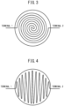
- FIGS. 3 and 4 are schematic cross-sectional views each showing an example of a shape of the heater.
- FIG. 3 is an example of a cross-sectional shape of the heater in which a double spiral heat-generating body is arranged inside a cylindrical housing.
- FIG. 4 is an example of a cross-sectional shape of the heater in which a zigzag heat-generating body is arranged inside a cylindrical housing.
- the heat-generating body generates heat by electric conduction through terminals 1 and 2 to heat gas passing through the heater.
- a heater in which a heat-generating body is arranged inside a cylinder of a cylindrical housing has an advantage of heating passing gas at high efficiency.
- the heater in the exhaust gas purification catalytic system of the present invention may be a heat disk.
- a “heat disk” is also referred to by terms such as “heating disk” and “heating device” in the art.
- a catalytic device provided with this heat disk is sometimes called an "EHC (electrically heated catalyst) system”.
- a "heat disk” refers to a heater which has a heat-generating body arranged inside a cylinder of a cylindrical housing and has a length shorter than the diameter thereof.
- the material of the heat-generating body of the heater is arbitrary as long as heat is generated by electric conduction, and may be a metallic heat-generating body or a non-metallic heat-generating body.
- the metallic heat-generating body may be, for example, an Fe-Cr-Al alloy, a Ni-Cr alloy, molybdenum, or tungsten.
- the non-metallic heat-generating body may be, for example, silicon carbide (Si-C), molybdenum silicide, lanthanum chromite, or carbon.
- the heater in the exhaust gas purification system of the present invention may be a commercially available product.
- EMICAT an electrically heated catalyst manufactured by Vitesco Technologies Emitec GmbH, can be suitably used.
- the heater may have no catalytic coating layer or may have a catalytic coating layer.
- the catalytic coating layer may be formed, for example, on one or both sides of one of the flat and corrugated sheets constituting the heater, or both thereof.
- the catalytic coating layer may have a configuration appropriately selected from among those described above as the configuration of the second catalytic coating layer.
- the heater may be arranged as a separate member from the metal honeycomb substrate of the first exhaust gas purification catalytic device, may be fixed to the exhaust gas flow downstream end of the metal honeycomb substrate, or may be formed integrally with the exhaust gas flow downstream side of the metal honeycomb substrate.
- the heater When the heater is fixed to the exhaust gas flow downstream end of the metal honeycomb substrate in the first exhaust gas purification catalytic device, the heater may be directly fixed to the metal honeycomb substrate without any interposition, or may be fixed indirectly using an appropriate fixation member. In any case, the fixation may be made by a known fixation method such as screw fixation or brazing.
- the second exhaust gas purification catalytic device in the exhaust gas purification catalytic system of the present invention comprises a cordierite honeycomb substrate and a second catalytic coating layer on the cordierite honeycomb substrate.
- cordierite honeycomb substrate in the second exhaust gas purification catalytic device of the exhaust gas purification catalytic system of the present invention for example, any cordierite honeycomb substrate known as a honeycomb substrate for automotive exhaust gas purification catalytic devices may be used.
- the size and shape of the cordierite substrate may be appropriately selected so as to match the size and shape of the exhaust system of an engine to which the exhaust gas purification catalytic system of the present invention is applied, for example, as a cylinder having a diameter of 60 mm or more and 165 mm or less and a length of 30 mm or more and 160 mm or less, or as a polygonal column having the same size.
- the cylinder or polygonal column may be bent halfway along the length direction.
- the second catalytic coating layer of the second exhaust gas purification catalytic device comprises inorganic oxide particles and catalyst particles supported by the inorganic oxide particles.
- the inorganic oxide particles in the second catalytic coating layer may be appropriately selected from among those described above as the inorganic oxide particles other than the adsorbent in the first catalytic coating layer.
- the catalytic noble metal particles in the second catalytic coating layer may be appropriately selected from among those described above as the catalytic noble metal particles in the first catalytic coating layer.
- the second catalytic coating layer may comprise an optional component, as needed, in addition to the inorganic oxide particles and the catalytic noble metal particles supported by the inorganic oxide particles.
- the optional component may be, for example, a binder.
- the binder may be appropriately selected from among those described above as the binder in the first catalytic coating layer.
- the second catalytic coating layer is intended to be warmed rapidly by a heater, and thus may comprise no adsorbent capable of adsorbing one or more of NOx, HC, and CO in a warmed state.
- ceria functions as an adsorbent in a cold state but exhibits dominant OSC ability in a warmed state, and thus may be contained in the second catalytic coating layer.
- the second catalytic coating layer may be configured so as to have a catalytic noble metal-enriched layer having an increased catalytic noble metal concentration on the exhaust gas flow upstream side, whereby the mass of the catalytic noble metal particles in the upstream half of the exhaust gas flow is greater than the mass of the catalytic noble metal particles in the downstream half of the exhaust gas flow.
- the second exhaust gas purification catalytic device arranged on the exhaust gas flow downstream side of the heater is warmed by the heat from the heater.
- the second exhaust gas purification catalytic device itself is gradually warmed from the exhaust gas flow upstream end. Therefore, by arranging more catalytic noble metal particles on the exhaust gas flow upstream side of the second catalytic coating layer, more catalytic noble metal particles are rapidly activated after a cold start, and exhaust gas purification efficiency can be remarkably increased at the time of the cold start.
- the mass of the catalytic noble metal particles in the upstream half of the exhaust gas flow in the second catalytic coating layer may be greater than 50% by mass, 55% by mass or greater, or 60% by mass or greater, and may be 90% by mass or less, 80% by mass or less, 75% by mass or less, 70% by mass or less, or 65% by mass or less, based on the total mass of the catalytic noble metal particles in the second catalytic coating layer.
- the second catalytic coating layer of the second exhaust gas purification catalytic device may be of a single layer or a multilayer having two or more layers, and may be a coating layer in a zonal configuration having a front-stage layer and a back-stage layer.
- the second catalytic coating layer may be, for example,
- the inorganic oxide particles contained in the lower layer of the second catalytic coating layer and the inorganic oxide particles contained in the upper layer may be of the same type, or may be of different types.
- the inorganic oxide particles in the second catalytic coating layer may be inorganic oxide particles other than the adsorbent.
- the catalytic noble metal particles contained in the lower layer of the second catalytic coating layer and the catalytic noble metal particles contained in the upper layer may be of the same type, or may be of different types.
- the catalytic noble metal particles contained in the lower layer of the second catalytic coating layer may be particles of one or two noble metals selected from Pd and Pt, and the catalytic noble metal particles contained in the upper layer may be particles of Rh.
- the lower layer of the second catalytic coating layer may be configured so as to have a catalytic noble metal-enriched layer having an increased catalytic noble metal concentration on the exhaust gas flow upstream side, whereby the mass of the catalytic noble metal particles in the upstream half of the exhaust gas flow of the lower layer is greater than the mass of the catalytic noble metal particles in the downstream half of the exhaust gas flow of the lower layer.
- the mass of the catalytic noble metal particles in the upstream half of the exhaust gas flow of the lower layer of the second catalytic coating layer may be greater than 50% by mass, 55% by mass or greater, or 60% by mass or greater, and may be 90% by mass or less, 80% by mass or less, 75% by mass or less, 70% by mass or less, or 65% by mass or less, based on the total mass of the catalytic noble metal particles in the lower layer of the second catalytic coating layer.
- the second catalytic coating layer may be, for example, a catalytic coating layer wherein
- the second catalytic coating layer may be, for example,
- the inorganic oxide particles contained in the downstream side catalyst layer of the second catalytic coating layer and the inorganic oxide particles contained in the upstream side catalyst layer may be of the same type, or may be of different types.
- the inorganic oxide particles in the second catalytic coating layer may be inorganic oxide particles other than the adsorbent.
- the catalytic noble metal particles contained in the downstream side catalyst layer of the second catalytic coating layer and the catalytic noble metal particles contained in the upstream side catalyst layer may be of the same type, or may be of different types.
- the catalytic noble metal particles contained in the downstream side catalyst layer of the second catalytic coating layer may be particles of one or two noble metals selected from Pd and Pt, and the catalytic noble metal particles contained in the upstream side catalyst layer may be particles of Rh.
- alumina particles, cerium-zirconium composite oxide particles, and alumina binder sol were dispersed to prepare a coating liquid for forming a Pd catalyst layer.
- a coating liquid for forming a Pd-enriched layer was prepared in the same manner as the above "1-1. Preparation of coating liquid for forming Pd catalyst layer".
- alumina particles, cerium-zirconium composite oxide particles, and alumina binder sol were dispersed. Thereafter, particles of BEA zeolite were further added and dispersed therein to prepare a coating liquid for forming a Pd catalyst/adsorption layer.
- alumina particles, cerium-zirconium composite oxide particles, and alumina binder sol were dispersed to prepare a coating liquid for forming a Rh catalyst layer.
- a metal honeycomb substrate made of stainless steel 600 cells, diameter of 118.4 mm, length of 50.0 mm, volume of about 0.551 L
- a cordierite honeycomb substrate 600 cells, diameter of 118.4 mm, length of 50.0 mm, volume of about 0.551 L
- a heat disk 600 cells, diameter of 118.4 mm, length of 50.0 mm, volume of about 0.551 L
- a heat disk 600 cells, diameter of 118.4 mm, length of 50.0 mm, volume of about 0.551 L
- two metal honeycomb substrates of the same type and a heat disk were provided with the respective predetermined coating layers and used.
- EMICAT (diameter of 118.4 mm, length of 10.0 mm, volume of about 0.110 L, made of metal), an electrically heated catalyst manufactured Vitesco Technologies Emitec GmbH, was used.
- a metal honeycomb substrate was coated with the coating liquid for forming a Pd catalyst/adsorption layer, and then dried and baked to form a Pd catalyst/adsorption layer.
- the Pd catalyst/adsorption layer was coated with the coating liquid for forming a Rh catalyst layer, and then dried and baked to form a Rh catalyst layer.
- a metal honeycomb substrate was coated with the coating liquid for forming a Pd catalyst layer, and then dried and baked to form a Pd catalyst layer.
- the Pd catalyst layer was coated with the coating liquid for forming a Rh catalyst layer, and then dried and baked to form a Rh catalyst layer.
- a cordierite honeycomb substrate was coated with the coating liquid for forming a Pd catalyst layer, and then dried and baked to form a Pd catalyst layer.
- the Pd catalyst layer was coated with the coating liquid for forming a Rh catalyst layer, and then dried and baked to form a Rh catalyst layer.
- the cordierite honeycomb substrate was coated with the coating liquid for forming a Pd catalyst layer on a region from the downstream end in the exhaust gas flow direction to 50% of the substrate length, and then dried.
- the substrate coated with the coating liquid for forming a Pd catalyst layer was then coated with the coating liquid for forming a Pd-enriched layer on a region from the upstream end in the exhaust gas flow direction to 50% of the substrate length, and then dried. Thereafter, the coated substrate was baked to form a Pd catalyst layer with a Pd-enriched layer.
- the coating liquid for forming a Rh catalyst layer was then coated on the Pd catalyst layer with a Pd-enriched layer, dried, and baked to form a Rh catalyst layer.
- the ratio of amounts of Pd on the exhaust gas flow upstream side of the catalyst layer to the downstream side was 3:2.
- the coating amounts of the coating liquid for forming a Pd catalyst layer and the coating liquid for forming a Pd-enriched layer were adjusted so that the total Pd content was the same as in the cordierite catalytic device in 3-3 above.
- a heat disk (“EMICAT”) was coated with the coating liquid for forming a Pd catalyst/adsorption layer, and then dried and baked to form a Pd catalyst/adsorption layer.
- the Pd catalyst/adsorption layer was coated with the coating liquid for forming a Rh catalyst layer, and then dried and baked to form a Rh catalyst layer.
- the exhaust gas purification catalytic system was subjected to endurance running and then evaluated by operating in WLTC mode using a cold start ratio of 100%.
- the exhaust gas purification catalytic system of each Example and Comparative Example was connected to an exhaust system of a gasoline engine (V-type 8-cylinder, displacement of 4,608 mL) on a bench, and subjected to endurance running in a pattern including a predetermined fuel cut at a catalyst bed temperature of 1,000 °C for 50 h.
- the exhaust gas purification catalytic system after the endurance running was connected to an exhaust system of an actual vehicle (gasoline engine automobile having a displacement of 1,500 mL) on a chassis dynamometer and operated in WLTC mode.
- the amount of NOx emissions in the entire mode at this time was determined and evaluated as the amount of NOx emissions per km of running.
- a heat disk with a coating layer was fixed using screws directly to the exhaust gas flow downstream side of a metal catalytic device (first exhaust gas purification catalytic device) with an adsorption function.
- a cordierite catalytic device (second exhaust gas purification catalytic device) was further arranged on the exhaust gas flow downstream side of the heat disk with a coating layer, whereby an exhaust gas purification catalytic system of Example 1 was formed, and evaluation was carried out.
- a heat disk with a coating layer was fixed using screws directly to the exhaust gas purification upstream side of one (first exhaust gas purification catalytic device) of the metal catalytic devices.
- the other metal catalytic device (second exhaust gas purification catalytic device) was arranged on the downstream side of the metal catalytic device to which the heat disk with a coating layer was fixed, whereby an exhaust gas purification catalytic system of Comparative Example 1 was formed, and evaluation was carried out.
- FIG. 5 A schematic view of a configuration of each of the exhaust gas purification catalytic systems produced in Examples 1 and 2 and Comparative Examples 1 to 4 is shown in FIG. 5 .
- the evaluation results of the Examples and Comparative Examples are shown in Table 2.
- the check mark in a heat disk column indicates that a heat disk was placed at that position.
- the same coating layer was formed on each of a metal honeycomb substrate (diameter of 103 mm, length of 110 mm) made of stainless steel (Reference Example 1) and a cordierite honeycomb substrate (diameter of 103 mm, length of 110 mm) (Reference Example 2).
- a metal honeycomb substrate (diameter of 103 mm, length of 110 mm) made of stainless steel (Reference Example 1)
- a cordierite honeycomb substrate (diameter of 103 mm, length of 110 mm) (Reference Example 2).
- Each substrate was coated with a coating liquid comprising palladium nitrate, rhodium nitrate, alumina particles, cerium-zirconium composite oxide particles, and alumina binder sol, and then dried and baked to obtain a metal honeycomb substrate with a coating layer (Reference Example 1) or a cordierite honeycomb substrate with a coating layer (Reference Example 2).
- a coating liquid comprising palladium nitrate, rhodium nitrate, alumina particles, cerium-zirconium composite oxide particles, and alumina binder sol
- Each substrate with a coating layer was mounted on an engine bench equipped with an engine having a displacement of 2,493 mL. Thereafter, the change over time of coating layer bed temperature inside the substrate (diametric center at a position of 60 mm from the exhaust gas flow upstream end of the substrate) when the exhaust gas controlled to 500 °C under stoichiometric conditions was circulated at 230 NmL/L/min as a flow rate per L of substrate volume per min was examined. The results are shown in FIG. 6 .
- the cordierite honeycomb substrate with a coating layer of Reference Example 2 had a faster rise in the coating layer bed temperature inside the substrate, compared to the metal honeycomb substrate with a coating layer of Reference Example 1.
- the bed temperature inside the metal honeycomb substrate with a coating layer of Reference Example 1 was about 310°C
- the bed temperature inside the substrate reached about 330°C. It is considered that this difference in how the coating layer bed temperature rises affects NOx emissions.
Landscapes
- Chemical & Material Sciences (AREA)
- Engineering & Computer Science (AREA)
- Chemical Kinetics & Catalysis (AREA)
- Organic Chemistry (AREA)
- Materials Engineering (AREA)
- Combustion & Propulsion (AREA)
- General Engineering & Computer Science (AREA)
- Mechanical Engineering (AREA)
- Health & Medical Sciences (AREA)
- Analytical Chemistry (AREA)
- Ceramic Engineering (AREA)
- Biomedical Technology (AREA)
- Environmental & Geological Engineering (AREA)
- Toxicology (AREA)
- General Chemical & Material Sciences (AREA)
- Oil, Petroleum & Natural Gas (AREA)
- Inorganic Chemistry (AREA)
- Crystallography & Structural Chemistry (AREA)
- Catalysts (AREA)
- Exhaust Gas Treatment By Means Of Catalyst (AREA)
- Exhaust Gas After Treatment (AREA)
- Treating Waste Gases (AREA)
Abstract
Description
- The present invention relates to an exhaust gas purification catalytic system.
- In recent years, electrically heated catalyst (EHC) devices have attracted attention as exhaust gas purification devices for purifying exhaust gas from automotive engines. By using an EHC, for example, even under conditions where the temperature of a catalyst bed is low and the catalyst is not easily activated, such as immediately after engine start, the catalyst is forcibly activated via electric heating, and exhaust gas purification can be enhanced.
- In a catalytic device comprising an EHC, heat generated by electric conduction in the EHC is transferred downstream by an exhaust gas flow, thereby warming the catalyst on the exhaust gas flow downstream side. Therefore, an EHC is positioned on the upstream side of an exhaust gas flow in a conventional catalytic device.
- For example,
PTL 1 discloses a metal support for electrically heated catalytic device comprising a honeycomb material obtained by laminating corrugated and flat sheets made of metal via an insulating sheet and winding into a comma shape; and an electrode portion comprising a two-part outer cylindrical portion arranged on the outer periphery of the honeycomb material, and describes that the metal support for electrically heated catalytic device is used in series with a metal support or a ceramic support provided downstream thereof. -
PTL 2 discloses an electrically heated catalytic device for exhaust gas purification, comprising an electrically heated pre-catalyst carrier and a main catalyst carrier on an exhaust gas downstream side of the pre-catalyst carrier. -
- [PTL 1]
Japanese Unexamined Patent Publication (Kokai) No. 11-253814 - [PTL 2]
Japanese Unexamined Patent Publication (Kokai) No. 11-179157 - In a catalytic device comprising an EHC, when the EHC is arranged most upstream in an exhaust gas flow, heat generated by electric conduction can be used effectively in a catalytic device on the downstream side from the EHC. However, for example, for a short period of time such as immediately after engine start, warmed area of the catalytic device on the downstream side is small, resulting in insufficient warming, whereby highly efficient exhaust gas purification expected from the EHC could not be enjoyed in many cases.
- An object of the present invention is to provide an exhaust gas purification system having a high exhaust gas purification efficiency even before a catalytic device is sufficiently warmed by an EHC, for example, immediately after engine start.
- The present invention is as follows.
- «
Aspect 1» An exhaust gas purification catalytic system, comprising, - in this order from an upstream side of an exhaust gas flow,
- a first exhaust gas purification catalytic device comprising a metal honeycomb substrate and a first catalytic coating on the metal honeycomb substrate,
- a heater, and
- a second exhaust gas purification catalytic device comprising a cordierite honeycomb substrate and a second catalytic coating layer on the cordierite honeycomb substrate, wherein
- the first catalytic coating layer comprises an adsorbent capable of adsorbing one or more of NOx, HC, and CO, and
- the second catalytic coating layer comprises inorganic oxide particles and catalytic noble metal particles supported by the inorganic oxide particles.
- «
Aspect 2» The exhaust gas purification catalytic system according toAspect 1, wherein the heater is a heat disk. - «
Aspect 3» The exhaust gas purification catalytic system according toAspect - «
Aspect 4» The exhaust gas purification catalytic system according toAspect - «
Aspect 5» The exhaust gas purification catalytic system according to any one ofAspects 1 to 4, wherein the adsorbent comprises inorganic oxide particles. - «Aspect 6» The exhaust gas purification catalytic system according to
Aspect 5, wherein the adsorbent comprises zeolite particles. - «Aspect 7» The exhaust gas purification catalytic system according to Aspect 6, wherein the zeolite particles include one or more selected from BEA zeolite, AEI zeolite, MFI zeolite, EMT zeolite, ERI zeolite, MOR zeolite, FER zeolite, FAU zeolite, CHA zeolite, LEV zeolite, MWW zeolite, CON zeolite, and EUO zeolite.
- «Aspect 8» The exhaust gas purification catalytic system according to any one of
Aspects 1 to 7, wherein
the first catalytic coating layer is - a catalytic coating layer having a two-layer configuration in which a lower layer and an upper layer are laminated in this order on the substrate, wherein
- the lower layer comprises an adsorbent, inorganic oxide particles other than the adsorbent, and catalytic noble metal particles, and the catalytic noble metal particles are supported by at least one of the adsorbent and the inorganic oxide particles other than the adsorbent, and
- the upper layer comprises inorganic oxide particles other than the adsorbent and catalytic noble metal particles, and the catalytic noble metal particles are supported by the inorganic oxide particles other than the adsorbent.
- «Aspect 9» The exhaust gas purification catalytic system according to any one of
Aspects 1 to 8, wherein in the second catalytic coating layer, a mass of the catalytic noble metal particles in an upstream half of an exhaust gas flow is greater than a mass of the catalytic noble metal particles in a downstream half of the exhaust gas flow. - «
Aspect 10» The exhaust gas purification catalytic system according to Aspect 9, wherein in the second catalytic coating layer, a mass of the catalytic noble metal particles in the upstream half of an exhaust gas flow is more than 50% by mass and 90% by mass or less, based on a total mass of the catalytic noble metal particles in the second catalytic coating layer. - «Aspect 11» The exhaust gas purification catalytic system according to any one of
Aspects 1 to 10, wherein
the second catalytic coating layer is - a catalytic coating layer having a two-layer configuration in which a lower layer and an upper layer are laminated in this order on the substrate, wherein
- the lower layer comprises inorganic oxide particles and catalytic noble metal particles, and the catalytic noble metal particles are supported by the inorganic oxide particles, and
- the upper layer comprises inorganic oxide particles and catalytic noble metal particles, and the catalytic noble metal particles are supported by the inorganic oxide particles.
- According to the present invention, an exhaust gas purification system having a high exhaust gas purification efficiency even before a catalytic device is sufficiently warmed by EHC is provided.
-
-
FIG. 1 is a schematic view showing an example of a basic configuration of the exhaust gas purification catalytic system of the present invention. -
FIG. 2 is a schematic view showing another example of a basic configuration of the exhaust gas purification catalytic system of the present invention. -
FIG. 3 is a schematic cross-sectional view showing an example of the shape of a heater in the exhaust gas purification catalytic system of the present invention. -
FIG. 4 is a schematic cross-sectional view showing another example of the shape of a heater in the exhaust gas purification catalytic system of the present invention. -
FIG. 5 is a schematic view showing configurations of the exhaust gas purification catalytic system produced in the Examples and Comparative Examples. -
FIG. 6 is a graph showing changes over time of coating layer bed temperature measured in the Reference Examples. - The exhaust gas purification catalytic system of the present invention is
- an exhaust gas purification catalytic system, comprising,
- in this order from an upstream side of an exhaust gas flow,
- a first exhaust gas purification catalytic device comprising a metal honeycomb substrate and a first catalytic coating layer on the metal honeycomb substrate,
- a heater, and
- a second exhaust gas purification catalytic device comprising a cordierite honeycomb substrate and a second catalytic coating layer on the cordierite honeycomb substrate, wherein
- the first catalytic coating layer comprises an adsorbent capable of adsorbing one or more of NOx, HC, and CO, and
- the second catalytic coating layer comprises inorganic oxide particles and catalytic noble metal particles supported by the inorganic oxide particles.
- The present invention focuses on the heat capacities of the metal honeycomb substrate and the cordierite honeycomb substrate.
- For example, the heat capacity of a metal honeycomb substrate made of 20Cr5Al-based stainless steel is compared to the heat capacity of a cordierite honeycomb substrate composed of 2MgO·2Al2O3·5SiO2. For the specific heat capacities of the materials themselves, cordierite is larger than stainless steel. However, the cordierite honeycomb substrate has a very small mass per L of substrate compared to the metal honeycomb substrate. Therefore, when the heat capacities per L of substrates are compared, the cordierite honeycomb substrate is smaller than the metal honeycomb substrate made of stainless steel.
- The above comparison is shown in Table 1.
-
Table 1. Metal substrate Cordierite substrate Material 20Cr5Al-based 2MgO·2Al2O3·5SiO2 Heat capacity per g of material (J/g·K) 0.48 0.73 Mass per L of substrate (g/L) 1,040 270 Heat capacity per L of substrate (J/g·K·L) 499 197 - In the present invention,
- a first exhaust gas purification catalytic device comprising a metal honeycomb substrate and a first catalytic coating layer on the metal honeycomb substrate,
- a heater (EHC), and
- a second exhaust gas purification catalytic device comprising a cordierite honeycomb substrate and a second catalytic coating layer on the cordierite honeycomb substrate are arranged in this order.
- The first catalytic coating layer of the first exhaust gas purification catalytic device comprises an adsorbent capable of adsorbing one or more of NOx, HC, and CO, and
the second catalytic coating layer of the second exhaust gas purification catalytic device comprises inorganic oxide particles and catalytic noble metal particles supported by these inorganic oxide particles. - The second exhaust gas purification catalytic device comprising a cordierite honeycomb substrate having a small heat capacity is arranged directly downstream of the exhaust gas flow from a heater, whereby the second exhaust gas purification catalytic device can be warmed rapidly by heat generated from electric conduction in the heater. Consequently, the catalytic noble metal particles in the catalytic coating layer are activated early, and the desired exhaust gas purification ability can be exhibited in an extremely short time after engine start.
- The first exhaust gas purification catalytic device comprising a metal honeycomb substrate having a large heat capacity is arranged on the exhaust gas flow upstream side of the heater. Since the first catalytic coating layer of the first exhaust gas purification catalytic device comprises an adsorbent, one or more of NOx, HC, and CO can be efficiently adsorbed in a cold state before warming.
- By arranging the first exhaust gas purification catalytic device on the exhaust gas flow upstream side of the heater, the first exhaust gas purification catalytic device is barely warmed by the heat from electric conduction in the heater and is solely warmed by (only) the heat of the exhaust gas. Moreover, since the heat capacity of the metal honeycomb substrate contained in the first exhaust gas purification catalytic device is large, the warming is carried out extremely slowly. As a result, one or more of NOx, HC, and CO in the exhaust gas, which are adsorbed in a cold state before the warming, are retained in the adsorbent in the first exhaust gas purification catalytic device for a long time. The time until the second exhaust gas purification catalytic device is warmed and the catalytic noble metal particles exhibit desired activity can be utilized.
- In the exhaust gas purification catalytic system of the present invention, a high exhaust gas purification efficiency can be obtained even before the system is sufficiently warmed by an EHC due to the mechanism of action described above.
- Hereinafter, with reference to the drawings, a basic configuration of the exhaust gas purification catalytic system of the present invention will be described. Basic configurations of the exhaust gas purification catalytic system of the present invention are shown in
FIGS. 1 and 2 . - The exhaust gas purification catalytic system in
FIG. 1 comprises, in this order from the upstream side of an exhaust gas flow, a first exhaust gas purification catalytic device (100), a heater (300), and a second exhaust gas purification catalytic device (200). - The first exhaust gas purification catalytic device (100) comprises a metal honeycomb substrate (110) and a first catalytic coating layer (120) on the metal honeycomb substrate (110). The first catalytic coating layer (120) includes an adsorbent (130) capable of adsorbing one or more of NOx, HC, and CO.
- The second exhaust gas purification catalytic device (200) comprises a cordierite honeycomb substrate (210) and a second catalytic coating layer (220) on the cordierite honeycomb substrate (210). The second catalytic coating layer (220) includes inorganic oxide particles (230) and catalytic noble metal particles (340) supported by the inorganic oxide particles (330). The inorganic oxide particles (330) in the second catalytic coating layer (320) may be inorganic oxide particles other than the adsorbent.
- The exhaust gas purification catalytic system in
FIG. 2 is the same as that inFIG. 1 , in that: - from the upstream side of an exhaust gas flow, a first exhaust gas purification catalytic device (100), a heater (300), and a second exhaust gas purification catalytic device (200) are contained in this order;
- the first exhaust gas purification catalytic device (100) comprises a metal honeycomb substrate (110) and a first catalytic coating layer (120) on the metal honeycomb substrate (110);
- the first catalytic coating layer (120) includes an adsorbent (130);
- the second exhaust gas purification catalytic device (200) comprises a cordierite honeycomb substrate (210) and a second catalytic coating layer (220) on the cordierite honeycomb substrate (210);
- the second catalytic coating layer (220) includes inorganic oxide particles and catalytic noble metal particles supported by the inorganic oxide particles; and
- the inorganic oxide particles in the second catalytic coating layer (220) may be inorganic oxide particles other than the adsorbent.
- However, in the exhaust gas purification catalytic system in
FIG. 2 , the first catalytic coating layer (120) of the first exhaust gas purification catalytic device (100) is a catalytic coating layer having a two-layer configuration in which a lower layer (121) and an upper layer (122) are laminated. - The lower layer (121) of the first catalytic coating layer (120) in the exhaust gas purification catalytic system in
FIG. 2 may comprise an adsorbent (130), inorganic oxide particles (131) other than the adsorbent, and catalytic noble metal particles (141). The catalytic noble metal particles (141) may be supported by at least one of the adsorbent and the inorganic oxide particles (131) other than the adsorbent (130). - The upper layer (122) of the first catalytic coating layer (120) comprises inorganic oxide particles (132) other than the adsorbent and catalytic noble metal particles (142). The catalytic noble metal particles (142) may be supported by the inorganic oxide particles (132) other than the adsorbent.
- In the exhaust gas purification catalytic system in
FIG. 2 , the second catalytic coating layer (220) of the second exhaust gas purification catalytic device (200) is a catalytic coating layer having two-layer configuration in which a lower layer (221) and an upper layer (222) are laminated. - The lower layer (221) of the second catalytic coating layer (220) in the exhaust gas purification catalytic system in
FIG. 2 comprises inorganic oxide particles (231) and catalytic noble metal particles (241). The catalytic noble metal particles (241) may be supported by the inorganic oxide particles (231). - The upper layer (222) of the second catalytic coating layer (220) comprises inorganic oxide particles (232) and catalytic noble metal particles (242). The catalytic noble metal particles (242) may be supported by the inorganic oxide particles (232).
- The first exhaust gas purification catalytic device comprises a metal honeycomb substrate and a first catalytic coating layer on the metal honeycomb substrate.
- The metal honeycomb substrate may be, for example, a honeycomb structure obtained by laminating metal flat and corrugated sheets and winding into a roll. In this case, the non-contacting portions of the flat sheet and the corrugated sheet may be configured with cells that run along the length direction of the honeycomb.
- The metal honeycomb substrate may comprise an outer cylinder around the honeycomb structure roll. This outer cylinder may be, for example, made of metal.
- The metal flat and corrugated sheets constituting the metal honeycomb substrate, as well as the outer cylinder, may each have perforations. However, in the present invention, from the viewpoint of maintaining a large heat capacity for the first exhaust gas purification catalytic device, one or more of the flat sheet, the corrugated sheet, and if present, the outer cylinder may have no perforations, or two or more thereof may have no perforations. Particularly, the flat sheet and the corrugated sheet may have no perforations. Further, if present, the outer cylinder may have no perforations.
- The size and shape of the metal honeycomb substrate may be appropriately selected so as to match the size and shape of the exhaust system of an engine to which the exhaust gas purification catalytic system of the present invention is applied, for example, as a cylinder having a diameter of 60 mm or more and 165 mm or less and a length of 30 mm or more and 160 mm or less, or as a polygonal column having the same size. The cylinder or polygonal column may be bent halfway along the length direction.
- The material of the metal honeycomb substrate may be a metal material, and may be, for example, a metal selected from Fe, Co, Ni, Al, Mg, Ti, Mo, W, Cr, Nb, and Ta, or an alloy comprising two or more thereof. Specifically, examples thereof can include stainless steel. Particularly, a known stainless steel may be used.
- The metal honeycomb substrate may be covered on the surface with an oxide coating. The oxide coating may be, for example, a thin film of Al2O3.
- The first catalytic coating layer of the first exhaust gas purification catalytic device comprises an adsorbent capable of adsorbing one or more of NOx, HC, and CO.
- The adsorbent in the first catalytic coating layer may include, for example, inorganic oxide particles.
- The inorganic oxide particles of the adsorbent may be, for example, particles of a zeolite, an alumina, an alkali metal oxide, an alkaline earth metal oxide, or a rare earth oxide. The alumina as the adsorbent may be one which has a large specific surface area among aluminas. Zeolites and aluminas preferably have porous structures from the viewpoint of having a large specific surface area.
- The zeolite may be, for example, BEA, AEI, MFI, EMT, ERI, MOR, FER, FAU, CHA, LEV, MWW, CON, or EUO zeolite.
- The alkali metal oxide may be, for example, an oxide comprising a metal such as sodium (Na), potassium (K), rubidium (Rb), or cesium (Cs). A potassium oxide is particularly preferable.
- The alkaline earth metal oxide may be, for example, an oxide of a metal selected from calcium (Ca), strontium (Sr), and barium (Ba). A barium oxide is particularly preferable.
- The rare earth oxide may be an oxide of a metal selected from cerium (Ce) and praseodymium (Pr). Oxides of Ce (ceria) are generally known in the art as a material having OSC (oxygen storage capacity) ability. However, ceria exhibits OSC ability in a warmed state, but does not exhibit OSC ability and functions as an adsorbent in a cold state. Therefore, ceria may be contained in the adsorbent in the first catalytic coating layer.
- Particles of an inorganic oxide having basic points can be used in the adsorption of NOx and CO. Therefore, for example, an adsorbent comprising particles of an alkali metal oxide, an alkaline earth metal oxide, a rare earth oxide, or a zeolite has a function of effectively adsorbing and desorbing NOx and CO.
- Particles of an inorganic oxide having acidic points can be used in the adsorption of HC. Therefore, for example, an adsorbent comprising particles of a zeolite or an alumina has a function of effectively adsorbing and desorbing HC.
- The first catalytic coating layer may comprise an optional component, as needed, in addition to the adsorbent. The optional component may be, for example, inorganic oxide particles other than the adsorbent, catalytic noble metal particles, or a binder.
- The inorganic oxide particles other than the adsorbent may be, for example, particles comprising one or more selected from alumina, silica, titania, ceria, zirconia, and rare earth metal oxides other than ceria. The alumina as the inorganic oxide particles other than the adsorbent may be one having a small specific surface area among aluminas. The rare earth metal oxide other than ceria may be an oxide of a metal such as yttrium, lanthanum, praseodymium, or neodymium.
- The catalytic noble metal particles may be, for example, of a platinum group metal. Specifically, the catalytic noble metal particles may be, for example, particles of one or more selected from palladium (Pd), platinum (Pt), and rhodium (Rh). The catalytic noble metal particles may be supported by the above inorganic oxide particles of the adsorbent, the inorganic oxide particles other than the adsorbent, or both.
- The binder may be, for example, a sol of an appropriate inorganic oxide such as alumina, titania, or zirconia.
- The first catalytic coating layer may be of a single layer or a multilayer having two or more layers, and may be a coating layer in a zonal configuration having a front-stage coating layer and a back-stage coating layer.
- The first catalytic coating layer may be, for example,
- a catalytic coating layer having a two-layer configuration in which a lower layer and an upper layer are laminated in this order on a substrate, wherein
- the lower layer comprises an adsorbent, inorganic oxide particles other than the adsorbent, and catalytic noble metal particles, and the catalytic noble metal particles are supported by at least one of the adsorbent and the inorganic oxide particles other than the adsorbent, and
- the upper layer comprises inorganic oxide particles other than the adsorbent and catalytic noble metal particles, and the catalytic noble metal particles are supported by the inorganic oxide particles other than the adsorbent.
- In this case, the inorganic oxide particles contained in the lower layer of the first catalytic coating layer and the inorganic oxide particles contained in the upper layer may be of the same type, or may be of different types.
- The catalytic noble metal particles contained in the lower layer of the first catalytic coating layer and the catalytic noble metal particles contained in the upper layer may be of the same type, or may be of different types. For example, the catalytic noble metal particles contained in the lower layer of the first catalytic coating layer may be particles of one or two noble metals selected from Pd and Pt, and the catalytic noble metal particles contained in the upper layer may be particles of Rh.
- Alternatively, the first catalytic coating layer may be, for example,
- a catalytic coating layer in a zonal configuration in which an exhaust gas flow upstream side catalyst layer and a downstream side catalyst layer are arranged on the substrate, wherein
- the downstream side catalyst layer comprises an adsorbent, inorganic oxide particles other than the adsorbent, and catalytic noble metal particles, and the catalytic noble metal particles are supported by at least one of the adsorbent and the inorganic oxide particles other than the adsorbent, and
- the upstream side catalyst layer comprises inorganic oxide particles other than the adsorbent and catalytic noble metal particles, and the catalytic noble metal particles are supported by the inorganic oxide particles other than the adsorbent.
- In this case, the inorganic oxide particles other than the adsorbent contained in the downstream side catalyst layer of the first catalytic coating layer and the inorganic oxide particles other than the adsorbent contained in the upstream side catalyst layer may be of the same type, or may be of different types.
- The catalytic noble metal particles contained in the downstream side catalyst layer of the first catalytic coating layer and the catalytic noble metal particles contained in the upstream side catalyst layer may be of the same type, or may be of different types. For example, the catalytic noble metal particles contained in the downstream side catalyst layer of the first catalytic coating layer may be particles of one or two metals selected from Pd and Pt, and the catalytic noble metal particles contained in the upstream side catalyst layer may be particles of Rh.
- In the exhaust gas purification catalytic system of the present invention, a heater is arranged between the exhaust gas flow downstream side of the first exhaust gas purification catalytic device and the exhaust gas flow upstream side of the second exhaust gas purification catalytic device.
- The heater generates heat, for example, by electric conduction, and has functions of heating gas discharged from the first exhaust gas purification catalytic device and then supplying the gas to the second exhaust gas purification catalytic device. In addition, the heater may have a function of heating the second exhaust gas purification catalytic device itself by heat generated from the heater.
- The shape of the heater is not limited as long as the above functions are included. For example, the heater may be cylindrical, or may be a heat-generating body of any shape, such as a honeycomb shape, a spiral shape, a double spiral shape, or a zigzag shape, arranged inside a cylindrical housing. The term "double spiral shape" described herein refers to a shape in which a spiral extending from the outer edge toward the center of a circle defining an outer periphery of the cylindrical housing and a spiral extending from the center toward the outer edge are connected at the center of the circle to form a single curved line as a whole. The term "zigzag shape" refers to a shape in which a straight line is bent many times in a "Z" shape.
-
FIGS. 3 and 4 are schematic cross-sectional views each showing an example of a shape of the heater.FIG. 3 is an example of a cross-sectional shape of the heater in which a double spiral heat-generating body is arranged inside a cylindrical housing.FIG. 4 is an example of a cross-sectional shape of the heater in which a zigzag heat-generating body is arranged inside a cylindrical housing. In each of the heaters inFIGS. 3 and 4 , the heat-generating body generates heat by electric conduction throughterminals - A heater in which a heat-generating body is arranged inside a cylinder of a cylindrical housing has an advantage of heating passing gas at high efficiency.
- The heater in the exhaust gas purification catalytic system of the present invention may be a heat disk. A "heat disk" is also referred to by terms such as "heating disk" and "heating device" in the art. A catalytic device provided with this heat disk is sometimes called an "EHC (electrically heated catalyst) system".
- As described herein, a "heat disk" refers to a heater which has a heat-generating body arranged inside a cylinder of a cylindrical housing and has a length shorter than the diameter thereof.
- The material of the heat-generating body of the heater is arbitrary as long as heat is generated by electric conduction, and may be a metallic heat-generating body or a non-metallic heat-generating body. The metallic heat-generating body may be, for example, an Fe-Cr-Al alloy, a Ni-Cr alloy, molybdenum, or tungsten. The non-metallic heat-generating body may be, for example, silicon carbide (Si-C), molybdenum silicide, lanthanum chromite, or carbon.
- The heater in the exhaust gas purification system of the present invention may be a commercially available product. For example, "EMICAT", an electrically heated catalyst manufactured by Vitesco Technologies Emitec GmbH, can be suitably used.
- The heater may have no catalytic coating layer or may have a catalytic coating layer.
- When the heater includes a catalytic coating layer, the catalytic coating layer may be formed, for example, on one or both sides of one of the flat and corrugated sheets constituting the heater, or both thereof. When the heater includes the catalytic coating layer, for example, the catalytic coating layer may have a configuration appropriately selected from among those described above as the configuration of the second catalytic coating layer.
- The heater may be arranged as a separate member from the metal honeycomb substrate of the first exhaust gas purification catalytic device, may be fixed to the exhaust gas flow downstream end of the metal honeycomb substrate, or may be formed integrally with the exhaust gas flow downstream side of the metal honeycomb substrate.
- When the heater is fixed to the exhaust gas flow downstream end of the metal honeycomb substrate in the first exhaust gas purification catalytic device, the heater may be directly fixed to the metal honeycomb substrate without any interposition, or may be fixed indirectly using an appropriate fixation member. In any case, the fixation may be made by a known fixation method such as screw fixation or brazing.
- The second exhaust gas purification catalytic device in the exhaust gas purification catalytic system of the present invention comprises a cordierite honeycomb substrate and a second catalytic coating layer on the cordierite honeycomb substrate.
- As the cordierite honeycomb substrate in the second exhaust gas purification catalytic device of the exhaust gas purification catalytic system of the present invention, for example, any cordierite honeycomb substrate known as a honeycomb substrate for automotive exhaust gas purification catalytic devices may be used.
- The size and shape of the cordierite substrate may be appropriately selected so as to match the size and shape of the exhaust system of an engine to which the exhaust gas purification catalytic system of the present invention is applied, for example, as a cylinder having a diameter of 60 mm or more and 165 mm or less and a length of 30 mm or more and 160 mm or less, or as a polygonal column having the same size. The cylinder or polygonal column may be bent halfway along the length direction.
- The second catalytic coating layer of the second exhaust gas purification catalytic device comprises inorganic oxide particles and catalyst particles supported by the inorganic oxide particles.
- The inorganic oxide particles in the second catalytic coating layer may be appropriately selected from among those described above as the inorganic oxide particles other than the adsorbent in the first catalytic coating layer.
- The catalytic noble metal particles in the second catalytic coating layer may be appropriately selected from among those described above as the catalytic noble metal particles in the first catalytic coating layer.
- The second catalytic coating layer may comprise an optional component, as needed, in addition to the inorganic oxide particles and the catalytic noble metal particles supported by the inorganic oxide particles. The optional component may be, for example, a binder. The binder may be appropriately selected from among those described above as the binder in the first catalytic coating layer.
- The second catalytic coating layer is intended to be warmed rapidly by a heater, and thus may comprise no adsorbent capable of adsorbing one or more of NOx, HC, and CO in a warmed state. Note that, ceria functions as an adsorbent in a cold state but exhibits dominant OSC ability in a warmed state, and thus may be contained in the second catalytic coating layer.
- The second catalytic coating layer may be configured so as to have a catalytic noble metal-enriched layer having an increased catalytic noble metal concentration on the exhaust gas flow upstream side, whereby the mass of the catalytic noble metal particles in the upstream half of the exhaust gas flow is greater than the mass of the catalytic noble metal particles in the downstream half of the exhaust gas flow.
- In the exhaust gas purification catalytic system of the present invention, the second exhaust gas purification catalytic device arranged on the exhaust gas flow downstream side of the heater is warmed by the heat from the heater. At this time, the second exhaust gas purification catalytic device itself is gradually warmed from the exhaust gas flow upstream end. Therefore, by arranging more catalytic noble metal particles on the exhaust gas flow upstream side of the second catalytic coating layer, more catalytic noble metal particles are rapidly activated after a cold start, and exhaust gas purification efficiency can be remarkably increased at the time of the cold start.
- From such a viewpoint, the mass of the catalytic noble metal particles in the upstream half of the exhaust gas flow in the second catalytic coating layer may be greater than 50% by mass, 55% by mass or greater, or 60% by mass or greater, and may be 90% by mass or less, 80% by mass or less, 75% by mass or less, 70% by mass or less, or 65% by mass or less, based on the total mass of the catalytic noble metal particles in the second catalytic coating layer.
- The second catalytic coating layer of the second exhaust gas purification catalytic device may be of a single layer or a multilayer having two or more layers, and may be a coating layer in a zonal configuration having a front-stage layer and a back-stage layer.
- The second catalytic coating layer may be, for example,
- a catalytic coating layer having a two-layer configuration in which a lower layer and an upper layer are laminated on a substrate, wherein
- the lower layer comprises inorganic oxide particles and catalytic noble metal particles, and the catalytic noble metal particles are supported by the inorganic oxide particles, and
- the upper layer comprises inorganic oxide particles and catalytic noble metal particles, and the catalytic noble metal particles are supported by the inorganic oxide particles.
- In this case, the inorganic oxide particles contained in the lower layer of the second catalytic coating layer and the inorganic oxide particles contained in the upper layer may be of the same type, or may be of different types. In any case, the inorganic oxide particles in the second catalytic coating layer may be inorganic oxide particles other than the adsorbent.
- The catalytic noble metal particles contained in the lower layer of the second catalytic coating layer and the catalytic noble metal particles contained in the upper layer may be of the same type, or may be of different types. For example, the catalytic noble metal particles contained in the lower layer of the second catalytic coating layer may be particles of one or two noble metals selected from Pd and Pt, and the catalytic noble metal particles contained in the upper layer may be particles of Rh.
- The lower layer of the second catalytic coating layer may be configured so as to have a catalytic noble metal-enriched layer having an increased catalytic noble metal concentration on the exhaust gas flow upstream side, whereby the mass of the catalytic noble metal particles in the upstream half of the exhaust gas flow of the lower layer is greater than the mass of the catalytic noble metal particles in the downstream half of the exhaust gas flow of the lower layer. In this case, the mass of the catalytic noble metal particles in the upstream half of the exhaust gas flow of the lower layer of the second catalytic coating layer may be greater than 50% by mass, 55% by mass or greater, or 60% by mass or greater, and may be 90% by mass or less, 80% by mass or less, 75% by mass or less, 70% by mass or less, or 65% by mass or less, based on the total mass of the catalytic noble metal particles in the lower layer of the second catalytic coating layer.
- In the above aspect, the second catalytic coating layer may be, for example, a catalytic coating layer wherein
- at least one of the lower layer and the upper layer is divided into exhaust gas flow upstream side and downstream side catalyst layers, and
- the mass of the noble metal particles per substrate unit volume in the exhaust gas flow upstream side catalyst layer is greater than the mass of the noble metal particles per substrate unit volume in the downstream side catalyst layer.
- Alternatively, the second catalytic coating layer may be, for example,
- a catalytic coating layer in a zonal configuration in which exhaust gas flow upstream side and downstream side catalyst layers are arranged on the substrate, wherein
- the downstream side catalyst layer comprises inorganic oxide particles and catalytic noble metal particles, and the catalytic noble metal particles are supported by the inorganic oxide particles, and
- the upstream side catalyst layer comprises inorganic oxide particles and catalytic noble metal particles, and the catalytic noble metal particles are supported by the inorganic oxide particles.
- In this case, the inorganic oxide particles contained in the downstream side catalyst layer of the second catalytic coating layer and the inorganic oxide particles contained in the upstream side catalyst layer may be of the same type, or may be of different types. In any case, the inorganic oxide particles in the second catalytic coating layer may be inorganic oxide particles other than the adsorbent.
- The catalytic noble metal particles contained in the downstream side catalyst layer of the second catalytic coating layer and the catalytic noble metal particles contained in the upstream side catalyst layer may be of the same type, or may be of different types. For example, the catalytic noble metal particles contained in the downstream side catalyst layer of the second catalytic coating layer may be particles of one or two noble metals selected from Pd and Pt, and the catalytic noble metal particles contained in the upstream side catalyst layer may be particles of Rh.
- In a solution obtained by dissolving palladium nitrate in ion-exchanged water, alumina particles, cerium-zirconium composite oxide particles, and alumina binder sol were dispersed to prepare a coating liquid for forming a Pd catalyst layer.
- Except that the amount of palladium nitrate used was increased by 1.5 times, a coating liquid for forming a Pd-enriched layer was prepared in the same manner as the above "1-1. Preparation of coating liquid for forming Pd catalyst layer".
- In a solution obtained by dissolving palladium nitrate in ion-exchanged water, alumina particles, cerium-zirconium composite oxide particles, and alumina binder sol were dispersed. Thereafter, particles of BEA zeolite were further added and dispersed therein to prepare a coating liquid for forming a Pd catalyst/adsorption layer.
- In a solution obtained by dissolving rhodium nitrate in ion-exchanged water, alumina particles, cerium-zirconium composite oxide particles, and alumina binder sol were dispersed to prepare a coating liquid for forming a Rh catalyst layer.
- A metal honeycomb substrate made of stainless steel (600 cells, diameter of 118.4 mm, length of 50.0 mm, volume of about 0.551 L), a cordierite honeycomb substrate (600 cells, diameter of 118.4 mm, length of 50.0 mm, volume of about 0.551 L), and a heat disk were provided with the respective predetermined coating layers of each of Examples and Comparative Examples and used as the substrate. In Comparative Examples 3 and 4, two metal honeycomb substrates of the same type and a heat disk were provided with the respective predetermined coating layers and used.
- As the heat disk, "EMICAT" (diameter of 118.4 mm, length of 10.0 mm, volume of about 0.110 L, made of metal), an electrically heated catalyst manufactured Vitesco Technologies Emitec GmbH, was used.
- A metal honeycomb substrate was coated with the coating liquid for forming a Pd catalyst/adsorption layer, and then dried and baked to form a Pd catalyst/adsorption layer. The Pd catalyst/adsorption layer was coated with the coating liquid for forming a Rh catalyst layer, and then dried and baked to form a Rh catalyst layer. By the above operations, a metal catalytic device, having on the metal honeycomb substrate a Pd catalyst/adsorption layer and a Rh catalyst layer, in this order, was produced.
- A metal honeycomb substrate was coated with the coating liquid for forming a Pd catalyst layer, and then dried and baked to form a Pd catalyst layer. The Pd catalyst layer was coated with the coating liquid for forming a Rh catalyst layer, and then dried and baked to form a Rh catalyst layer. By the above operations, a metal catalytic device, having on the metal honeycomb substrate a Pd catalyst layer and a Rh catalyst layer, in this order, was produced.
- A cordierite honeycomb substrate was coated with the coating liquid for forming a Pd catalyst layer, and then dried and baked to form a Pd catalyst layer. The Pd catalyst layer was coated with the coating liquid for forming a Rh catalyst layer, and then dried and baked to form a Rh catalyst layer. By the above operations, a cordierite catalytic device, having on the cordierite honeycomb substrate a Pd catalyst layer and a Rh catalyst layer, in this order, was produced.
- The cordierite honeycomb substrate was coated with the coating liquid for forming a Pd catalyst layer on a region from the downstream end in the exhaust gas flow direction to 50% of the substrate length, and then dried. The substrate coated with the coating liquid for forming a Pd catalyst layer was then coated with the coating liquid for forming a Pd-enriched layer on a region from the upstream end in the exhaust gas flow direction to 50% of the substrate length, and then dried. Thereafter, the coated substrate was baked to form a Pd catalyst layer with a Pd-enriched layer. The coating liquid for forming a Rh catalyst layer was then coated on the Pd catalyst layer with a Pd-enriched layer, dried, and baked to form a Rh catalyst layer. By the above operations, a cordierite catalytic device, having on the cordierite honeycomb substrate a Pd catalyst layer with a Pd-enriched layer and a Rh catalyst layer, in this order, was produced.
- In the cordierite catalytic device with a Pd-enriched layer, the ratio of amounts of Pd on the exhaust gas flow upstream side of the catalyst layer to the downstream side was 3:2. The coating amounts of the coating liquid for forming a Pd catalyst layer and the coating liquid for forming a Pd-enriched layer were adjusted so that the total Pd content was the same as in the cordierite catalytic device in 3-3 above.
- A heat disk ("EMICAT") was coated with the coating liquid for forming a Pd catalyst/adsorption layer, and then dried and baked to form a Pd catalyst/adsorption layer. The Pd catalyst/adsorption layer was coated with the coating liquid for forming a Rh catalyst layer, and then dried and baked to form a Rh catalyst layer. By the above operations, a heat disk with a coating layer, having on the heat disk a Pd catalyst/adsorption layer and a Rh catalyst layer, in this order, was produced.
- The exhaust gas purification catalytic system was subjected to endurance running and then evaluated by operating in WLTC mode using a cold start ratio of 100%.
- The exhaust gas purification catalytic system of each Example and Comparative Example was connected to an exhaust system of a gasoline engine (V-type 8-cylinder, displacement of 4,608 mL) on a bench, and subjected to endurance running in a pattern including a predetermined fuel cut at a catalyst bed temperature of 1,000 °C for 50 h.
- The exhaust gas purification catalytic system after the endurance running was connected to an exhaust system of an actual vehicle (gasoline engine automobile having a displacement of 1,500 mL) on a chassis dynamometer and operated in WLTC mode. The amount of NOx emissions in the entire mode at this time was determined and evaluated as the amount of NOx emissions per km of running.
- A heat disk with a coating layer was fixed using screws directly to the exhaust gas flow downstream side of a metal catalytic device (first exhaust gas purification catalytic device) with an adsorption function. A cordierite catalytic device (second exhaust gas purification catalytic device) was further arranged on the exhaust gas flow downstream side of the heat disk with a coating layer, whereby an exhaust gas purification catalytic system of Example 1 was formed, and evaluation was carried out.
- Except that a cordierite catalytic device with a Pd-enriched layer was used as the second exhaust gas purification catalytic device, an exhaust gas purification catalytic system was formed in the same manner as in Example 1, and evaluation was carried out.
- In Comparative Example 1, metal catalytic devices were used for both the first exhaust gas purification catalytic device and the second exhaust gas purification catalytic device, and evaluation was carried out.
- A heat disk with a coating layer was fixed using screws directly to the exhaust gas purification upstream side of one (first exhaust gas purification catalytic device) of the metal catalytic devices. The other metal catalytic device (second exhaust gas purification catalytic device) was arranged on the downstream side of the metal catalytic device to which the heat disk with a coating layer was fixed, whereby an exhaust gas purification catalytic system of Comparative Example 1 was formed, and evaluation was carried out.
- Except that the heat disk with a coating layer was fixed using screws directly to the exhaust gas flow upstream side of the first exhaust gas purification catalytic device, an exhaust gas purification catalytic system was formed in the same manner as in Example 1, and evaluation was carried out.
- Except that the fixing location of the heat disk with a coating layer was changed to the exhaust gas flow downstream side of the first exhaust gas purification catalytic device, which was a metal catalytic device, an exhaust gas purification catalytic system was formed in the same manner as in Comparative Example 1, and evaluation was carried out.
- Except that the fixing location of the heat disk with a coating layer was changed to the exhaust gas flow downstream side of the first exhaust gas purification catalytic device, which was a metal catalytic device with an adsorption function, an exhaust gas purification catalytic system was formed in the same manner as in Comparative Example 2, and evaluation was carried out.
- A schematic view of a configuration of each of the exhaust gas purification catalytic systems produced in Examples 1 and 2 and Comparative Examples 1 to 4 is shown in
FIG. 5 . The evaluation results of the Examples and Comparative Examples are shown in Table 2. -
Table 2. Configuration of exhaust gas purification catalytic system WLTC mode NOx discharge amount [g/km] Exhaust gas flow → Heat disk First exhaust gas purification catalytic device Heat disk Second exhaust gas purification catalytic device Example 1 Metal catalytic device with adsorption function ✔ Cordierite catalytic device 0.036 Example 2 Metal catalytic device with adsorption function ✔ Cordierite catalytic device with Pd-enriched laver 0.030 Comparative Example 1 ✔ Metal catalytic device Metal catalytic device 0.051 Comparative Example 2 ✔ Metal catalytic device with adsorption function Cordierite catalytic device 0.049 Comparative Example 3 Metal catalytic device ✔ Metal catalytic device 0.050 Comparative Example 4 Metal catalytic device with adsorption function ✔ Metal catalytic device 0.047 - The check mark in a heat disk column indicates that a heat disk was placed at that position.
- With reference to the above Table 2, it was confirmed that NOx emissions were reduced in the exhaust gas purification catalytic systems of Examples 1 and 2, wherein the heat disk was arranged on the exhaust gas flow downstream side of the metal catalytic device with an adsorption function and the cordierite catalytic device was further arranged on the downstream side thereof, compared to the systems of the Comparative Examples. It should be noted that the catalyst evaluations in the above Examples and Comparative Examples herein were carried out in WLTC mode, excluding warm start and using a cold start ratio of 100%.
- The above results are considered to be the result of rapid warming of the cordierite catalytic device (second exhaust gas purification catalytic device), which has a small heat capacity, by the heat disk arranged on the exhaust gas flow downstream side of the metal catalytic device (first exhaust gas purification catalytic device) with an adsorption function.
- For the Reference Examples, the same coating layer was formed on each of a metal honeycomb substrate (diameter of 103 mm, length of 110 mm) made of stainless steel (Reference Example 1) and a cordierite honeycomb substrate (diameter of 103 mm, length of 110 mm) (Reference Example 2). Each substrate was examined on how the temperature inside the substrate rises when a high-temperature gas was introduced therein.
- Each substrate was coated with a coating liquid comprising palladium nitrate, rhodium nitrate, alumina particles, cerium-zirconium composite oxide particles, and alumina binder sol, and then dried and baked to obtain a metal honeycomb substrate with a coating layer (Reference Example 1) or a cordierite honeycomb substrate with a coating layer (Reference Example 2).
- Each substrate with a coating layer was mounted on an engine bench equipped with an engine having a displacement of 2,493 mL. Thereafter, the change over time of coating layer bed temperature inside the substrate (diametric center at a position of 60 mm from the exhaust gas flow upstream end of the substrate) when the exhaust gas controlled to 500 °C under stoichiometric conditions was circulated at 230 NmL/L/min as a flow rate per L of substrate volume per min was examined. The results are shown in
FIG. 6 . - With reference to
FIG. 6 , it was found that the cordierite honeycomb substrate with a coating layer of Reference Example 2 had a faster rise in the coating layer bed temperature inside the substrate, compared to the metal honeycomb substrate with a coating layer of Reference Example 1. For example, at an elapsed time of 25 s, the bed temperature inside the metal honeycomb substrate with a coating layer of Reference Example 1 was about 310°C, whereas in the cordierite honeycomb substrate with a coating layer of Reference Example 2, the bed temperature inside the substrate reached about 330°C. It is considered that this difference in how the coating layer bed temperature rises affects NOx emissions. -
- 100
- first exhaust gas purification catalytic device
- 110
- metal honeycomb substrate
- 120
- first catalytic coating layer
- 121
- lower layer
- 122
- upper layer
- 130
- adsorbent
- 131, 132
- inorganic oxide particle
- 141, 142
- catalytic noble metal particle
- 200
- second exhaust gas purification catalytic device
- 210
- cordierite honeycomb substrate
- 220
- second catalytic coating layer
- 221
- lower layer
- 222
- upper layer
- 230, 231, 232
- inorganic oxide particle
- 240, 241, 242
- catalytic noble metal particle
- 300
- heater
Claims (11)
- An exhaust gas purification catalytic system, comprising,in this order from an upstream side of an exhaust gas flow,a first exhaust gas purification catalytic device comprising a metal honeycomb substrate and a first catalytic coating layer on the metal honeycomb substrate,a heater, anda second exhaust gas purification catalytic device comprising a cordierite honeycomb substrate and a second catalytic coating layer on the cordierite honeycomb substrate, whereinthe first catalytic coating layer comprises an adsorbent capable of adsorbing one or more of NOx, HC, and CO, andthe second catalytic coating layer comprises inorganic oxide particles and catalytic noble metal particles supported by the inorganic oxide particles.
- The exhaust gas purification catalytic system according to claim 1, wherein the heater is a heat disk.
- The exhaust gas purification catalytic system according to claim 1 or 2, wherein the heater is fixed to an exhaust gas flow downstream end of the metal honeycomb substrate.
- The exhaust gas purification catalytic system according to claim 1 or 2, wherein the heater is formed integrally with an exhaust gas flow downstream side of the metal honeycomb substrate.
- The exhaust gas purification catalytic system according to any one of claims 1 to 4, wherein the adsorbent comprises inorganic oxide particles.
- The exhaust gas purification catalytic system according to claim 5, wherein the adsorbent comprises zeolite particles.
- The exhaust gas purification catalytic system according to claim 6, wherein the zeolite particles include one or more selected from BEA zeolite, AEI zeolite, MFI zeolite, EMT zeolite, ERI zeolite, MOR zeolite, FER zeolite, FAU zeolite, CHA zeolite, LEV zeolite, MWW zeolite, CON zeolite, and EUO zeolite.
- The exhaust gas purification catalytic system according to any one of claims 1 to 7, wherein
the first catalytic coating layer isa catalytic coating layer having a two-layer configuration in which a lower layer and an upper layer are laminated in this order on the substrate, whereinthe lower layer comprises an adsorbent, inorganic oxide particles other than the adsorbent, and catalytic noble metal particles, and the catalytic noble metal particles are supported by at least one of the adsorbent and the inorganic oxide particles other than the adsorbent, andthe upper layer comprises inorganic oxide particles other than the adsorbent and catalytic noble metal particles, and the catalytic noble metal particles are supported by the inorganic oxide particles other than the adsorbent. - The exhaust gas purification catalytic system according to any one of claims 1 to 8, wherein in the second catalytic coating layer, a mass of the catalytic noble metal particles in an upstream half of an exhaust gas flow is greater than a mass of the catalytic noble metal particles in a downstream half of the exhaust gas flow.
- The exhaust gas purification catalytic system according to claim 9, wherein in the second catalytic coating layer, a mass of the catalytic noble metal particles in the upstream half of an exhaust gas flow is more than 50% by mass and 90% by mass or less, based on a total mass of the catalytic noble metal particles in the second catalytic coating layer.
- The exhaust gas purification catalytic system according to any one of claims 1 to 10, wherein
the second catalytic coating layer isa catalytic coating layer having a two-layer configuration in which a lower layer and an upper layer are laminated in this order on the substrate, whereinthe lower layer comprises inorganic oxide particles and catalytic noble metal particles, and the catalytic noble metal particles are supported by the inorganic oxide particles, andthe upper layer comprises inorganic oxide particles and catalytic noble metal particles, and the catalytic noble metal particles are supported by the inorganic oxide particles.
Applications Claiming Priority (2)
| Application Number | Priority Date | Filing Date | Title |
|---|---|---|---|
| JP2020123786A JP7248626B2 (en) | 2020-07-20 | 2020-07-20 | Exhaust gas purification catalyst system |
| PCT/JP2021/025504 WO2022019108A1 (en) | 2020-07-20 | 2021-07-06 | Exhaust gas purification catalyst system |
Publications (2)
| Publication Number | Publication Date |
|---|---|
| EP4183474A1 true EP4183474A1 (en) | 2023-05-24 |
| EP4183474A4 EP4183474A4 (en) | 2024-07-17 |
Family
ID=79729702
Family Applications (1)
| Application Number | Title | Priority Date | Filing Date |
|---|---|---|---|
| EP21846370.1A Pending EP4183474A4 (en) | 2020-07-20 | 2021-07-06 | CATALYST SYSTEM FOR EXHAUST GAS PURIFICATION |
Country Status (5)
| Country | Link |
|---|---|
| US (1) | US20230294044A1 (en) |
| EP (1) | EP4183474A4 (en) |
| JP (1) | JP7248626B2 (en) |
| CN (1) | CN116133745B (en) |
| WO (1) | WO2022019108A1 (en) |
Family Cites Families (26)
| Publication number | Priority date | Publication date | Assignee | Title |
|---|---|---|---|---|
| JPH0256247A (en) * | 1988-05-17 | 1990-02-26 | Toyota Motor Corp | Exhaust purification catalyst |
| US5296198A (en) * | 1990-11-09 | 1994-03-22 | Ngk Insulators, Ltd. | Heater and catalytic converter |
| JPH051525A (en) * | 1990-11-15 | 1993-01-08 | Ngk Spark Plug Co Ltd | Exhaust gas purification device for internal combustion engine using catalytic converter |
| US5248251A (en) * | 1990-11-26 | 1993-09-28 | Catalytica, Inc. | Graded palladium-containing partial combustion catalyst and a process for using it |
| JPH0559939A (en) * | 1991-06-19 | 1993-03-09 | Ngk Spark Plug Co Ltd | Catalytic exhaust emission control device with heater |
| US5597771A (en) * | 1993-06-25 | 1997-01-28 | Engelhard Corporation | Layered catalyst composite |
| WO1995008702A1 (en) * | 1993-09-24 | 1995-03-30 | W.R. Grace & Co.-Conn. | Combined hydrocarbon trap and electrically heatable converter |
| JP3526084B2 (en) * | 1993-12-28 | 2004-05-10 | 日本碍子株式会社 | Adsorption / catalyst for exhaust gas purification, adsorbent, exhaust gas purification system and exhaust gas purification method |
| JPH10169434A (en) * | 1996-12-09 | 1998-06-23 | Ngk Insulators Ltd | Exhaust emission control method and exhaust emission control system used for the same |
| JPH115021A (en) * | 1997-06-16 | 1999-01-12 | Ngk Insulators Ltd | Exhaust gas purifying system |
| JPH11179157A (en) | 1997-12-25 | 1999-07-06 | Nippon Steel Corp | Electric heating catalyst device |
| JPH11200843A (en) * | 1998-01-16 | 1999-07-27 | Nissan Motor Co Ltd | Exhaust gas purification device for internal combustion engine |
| JPH11253814A (en) | 1998-03-16 | 1999-09-21 | Showa Aircraft Ind Co Ltd | Metal carrier for electric heating type catalytic device |
| JP2001173437A (en) * | 1999-12-17 | 2001-06-26 | Denso Corp | Exhaust gas purification device for internal combustion engine |
| JP2002004846A (en) * | 2000-06-27 | 2002-01-09 | Honda Motor Co Ltd | Exhaust gas purification device for internal combustion engine |
| DE10051562A1 (en) * | 2000-10-18 | 2002-04-25 | Emitec Emissionstechnologie | Electrically heated honeycomb body used for removing hydrocarbons or nitrogen oxides from I.C. engine exhaust gases comprises two zones with different coatings arranged behind each other in the flow direction |
| CN1680689A (en) * | 2004-04-08 | 2005-10-12 | 中国环境科学研究院 | Electric heaters for exhaust purification devices of internal combustion engines |
| JP2008057446A (en) * | 2006-08-31 | 2008-03-13 | Toyota Motor Corp | Exhaust gas purification device for internal combustion engine |
| JP2010203419A (en) * | 2009-03-06 | 2010-09-16 | Toyota Motor Corp | Exhaust emission control device for hybrid vehicle |
| DE102011117624A1 (en) * | 2011-11-04 | 2013-05-08 | Emitec Gesellschaft Für Emissionstechnologie Mbh | Exhaust treatment device |
| JP6186860B2 (en) * | 2013-05-07 | 2017-08-30 | いすゞ自動車株式会社 | Hybrid engine and control method thereof |
| GB2518418A (en) * | 2013-09-20 | 2015-03-25 | Johnson Matthey Plc | Electrically heated catalyst for a compression ignition engine |
| JP2017014969A (en) * | 2015-06-30 | 2017-01-19 | トヨタ自動車株式会社 | Exhaust emission control device for internal combustion engine |
| JP6387976B2 (en) * | 2016-02-05 | 2018-09-12 | トヨタ自動車株式会社 | Electric heating type catalyst |
| EP3443208B1 (en) * | 2016-04-13 | 2023-01-04 | Johnson Matthey Public Limited Company | Exhaust system for a diesel engine |
| DE102017113712A1 (en) * | 2017-06-21 | 2018-12-27 | Volkswagen Aktiengesellschaft | Exhaust gas aftertreatment system and method for exhaust aftertreatment of an internal combustion engine |
-
2020
- 2020-07-20 JP JP2020123786A patent/JP7248626B2/en active Active
-
2021
- 2021-07-06 CN CN202180060812.3A patent/CN116133745B/en active Active
- 2021-07-06 US US18/014,273 patent/US20230294044A1/en active Pending
- 2021-07-06 EP EP21846370.1A patent/EP4183474A4/en active Pending
- 2021-07-06 WO PCT/JP2021/025504 patent/WO2022019108A1/en not_active Ceased
Also Published As
| Publication number | Publication date |
|---|---|
| CN116133745B (en) | 2024-10-29 |
| JP2022020346A (en) | 2022-02-01 |
| JP7248626B2 (en) | 2023-03-29 |
| CN116133745A (en) | 2023-05-16 |
| EP4183474A4 (en) | 2024-07-17 |
| US20230294044A1 (en) | 2023-09-21 |
| WO2022019108A1 (en) | 2022-01-27 |
Similar Documents
| Publication | Publication Date | Title |
|---|---|---|
| JP6441319B2 (en) | Electric heating catalysts for compression ignition engines | |
| JP3724708B2 (en) | Exhaust gas purification catalyst | |
| EP1308200B1 (en) | Exhaust gas purifying catalyst | |
| CN101227977B (en) | Exhaust gas purifying catalyst | |
| CN101069833B (en) | Hydrocarbon adsorbent, catalyst for treating exhaust gas and method for purifying exhaust gas | |
| EP3892837B1 (en) | Exhaust gas purging device | |
| WO2022097498A1 (en) | Exhaust gas purification catalyst device | |
| WO2021261209A1 (en) | Exhaust gas purification catalyst | |
| JP4460844B2 (en) | Exhaust gas purification catalyst and exhaust gas purification method | |
| JP7153039B2 (en) | Exhaust gas purification system for internal combustion engine | |
| EP3932550A1 (en) | Catalyst for purifying exhaust gas | |
| EP1717422B1 (en) | Exhaust gas purifying method | |
| JP2009285605A (en) | Catalyst for cleaning exhaust gas | |
| JP2003201832A (en) | Exhaust gas purification catalyst system | |
| EP2347822A1 (en) | Diesel exhaust gas purification catalyst and diesel exhaust gas purification system | |
| EP4183474A1 (en) | Exhaust gas purification catalyst system | |
| JP2009208045A (en) | Exhaust gas cleaning catalyst | |
| JP2002210371A (en) | Exhaust gas purification catalyst | |
| JP4413366B2 (en) | Exhaust gas purification catalyst | |
| JP7245613B2 (en) | Exhaust gas purification catalyst device | |
| JP4923412B2 (en) | Exhaust gas purification catalyst | |
| CN120787180A (en) | Exhaust gas purifying catalyst device and exhaust gas purifying catalyst system | |
| JP3682851B2 (en) | Exhaust gas purification system | |
| WO2025134852A1 (en) | Exhaust gas purification catalyst, method for producing same, and method for purifying exhaust gas using said exhaust gas purification catalyst | |
| JP2003200063A (en) | Exhaust gas purification catalyst, method for producing the same, and exhaust gas purification system |
Legal Events
| Date | Code | Title | Description |
|---|---|---|---|
| STAA | Information on the status of an ep patent application or granted ep patent |
Free format text: STATUS: THE INTERNATIONAL PUBLICATION HAS BEEN MADE |
|
| PUAI | Public reference made under article 153(3) epc to a published international application that has entered the european phase |
Free format text: ORIGINAL CODE: 0009012 |
|
| STAA | Information on the status of an ep patent application or granted ep patent |
Free format text: STATUS: REQUEST FOR EXAMINATION WAS MADE |
|
| 17P | Request for examination filed |
Effective date: 20221229 |
|
| AK | Designated contracting states |
Kind code of ref document: A1 Designated state(s): AL AT BE BG CH CY CZ DE DK EE ES FI FR GB GR HR HU IE IS IT LI LT LU LV MC MK MT NL NO PL PT RO RS SE SI SK SM TR |
|
| DAV | Request for validation of the european patent (deleted) | ||
| DAX | Request for extension of the european patent (deleted) | ||
| REG | Reference to a national code |
Ref country code: DE Ref legal event code: R079 Free format text: PREVIOUS MAIN CLASS: B01D0053920000 Ipc: B01D0053940000 |
|
| A4 | Supplementary search report drawn up and despatched |
Effective date: 20240619 |
|
| RIC1 | Information provided on ipc code assigned before grant |
Ipc: F01N 3/28 20060101ALI20240613BHEP Ipc: F01N 3/20 20060101ALI20240613BHEP Ipc: F01N 3/08 20060101ALI20240613BHEP Ipc: B01J 37/02 20060101ALI20240613BHEP Ipc: B01J 35/00 20060101ALI20240613BHEP Ipc: B01J 29/70 20060101ALI20240613BHEP Ipc: B01J 23/63 20060101ALI20240613BHEP Ipc: B01D 53/94 20060101AFI20240613BHEP |