EP4183307A1 - Dishwasher - Google Patents
Dishwasher Download PDFInfo
- Publication number
- EP4183307A1 EP4183307A1 EP22207730.7A EP22207730A EP4183307A1 EP 4183307 A1 EP4183307 A1 EP 4183307A1 EP 22207730 A EP22207730 A EP 22207730A EP 4183307 A1 EP4183307 A1 EP 4183307A1
- Authority
- EP
- European Patent Office
- Prior art keywords
- guide
- duct
- dry air
- tub
- airflow
- Prior art date
- Legal status (The legal status is an assumption and is not a legal conclusion. Google has not performed a legal analysis and makes no representation as to the accuracy of the status listed.)
- Granted
Links
Images











Classifications
-
- A—HUMAN NECESSITIES
- A47—FURNITURE; DOMESTIC ARTICLES OR APPLIANCES; COFFEE MILLS; SPICE MILLS; SUCTION CLEANERS IN GENERAL
- A47L—DOMESTIC WASHING OR CLEANING; SUCTION CLEANERS IN GENERAL
- A47L15/00—Washing or rinsing machines for crockery or tableware
- A47L15/42—Details
- A47L15/48—Drying arrangements
- A47L15/488—Connections of the tub with the ambient air, e.g. air intake or venting arrangements
-
- A—HUMAN NECESSITIES
- A47—FURNITURE; DOMESTIC ARTICLES OR APPLIANCES; COFFEE MILLS; SPICE MILLS; SUCTION CLEANERS IN GENERAL
- A47L—DOMESTIC WASHING OR CLEANING; SUCTION CLEANERS IN GENERAL
- A47L15/00—Washing or rinsing machines for crockery or tableware
- A47L15/42—Details
- A47L15/4246—Details of the tub
-
- A—HUMAN NECESSITIES
- A47—FURNITURE; DOMESTIC ARTICLES OR APPLIANCES; COFFEE MILLS; SPICE MILLS; SUCTION CLEANERS IN GENERAL
- A47L—DOMESTIC WASHING OR CLEANING; SUCTION CLEANERS IN GENERAL
- A47L15/00—Washing or rinsing machines for crockery or tableware
- A47L15/42—Details
- A47L15/48—Drying arrangements
-
- A—HUMAN NECESSITIES
- A47—FURNITURE; DOMESTIC ARTICLES OR APPLIANCES; COFFEE MILLS; SPICE MILLS; SUCTION CLEANERS IN GENERAL
- A47L—DOMESTIC WASHING OR CLEANING; SUCTION CLEANERS IN GENERAL
- A47L15/00—Washing or rinsing machines for crockery or tableware
- A47L15/42—Details
- A47L15/4251—Details of the casing
-
- A—HUMAN NECESSITIES
- A47—FURNITURE; DOMESTIC ARTICLES OR APPLIANCES; COFFEE MILLS; SPICE MILLS; SUCTION CLEANERS IN GENERAL
- A47L—DOMESTIC WASHING OR CLEANING; SUCTION CLEANERS IN GENERAL
- A47L15/00—Washing or rinsing machines for crockery or tableware
- A47L15/42—Details
- A47L15/48—Drying arrangements
- A47L15/486—Blower arrangements
Definitions
- a dishwasher and in particular, a dishwasher that can prevent an airflow guide from clattering effectively without an additional member and support the airflow guide reliably, allow a lower end surface of a fastening nut to be exposed to a wash space, prevent wash water from remaining between the fastening nut and a tub, and prevent the tub and a dry air supply hole from corroding.
- Dishwashers spray wash water such as water to a wash target such as cooking vessels, cooking tools and the like accommodated in them to wash the wash target.
- wash water used for washing a wash target can include detergent.
- dishwashers are comprised of a tub forming a wash space, a storage part accommodating wash targets in the tub, a spray arm spraying wash water to the storage part, and a sump storing water and supplying wash water to the spray arm.
- Dishwashers help to reduce time and efforts taken to clean wash targets such as cooking vessels and the like after meals, thereby ensuring improvement in user convenience.
- dishwashers perform a washing process of washing wash targets, a rinsing process of rinsing the wash targets, and a drying process of drying the wash targets after the washing and rinsing processes.
- the drying stage of dishwashers involves supplying high-temperature dry air into the tub to reduce a drying period and promote the effect of sterilizing wash targets.
- a dry air spray part for spraying dry air generated through the hot air supply device, which is disposed under of a tub, into the tub is disposed in the tub.
- the dry air spray part is coupled to a hot air supply tube that extends in a way that penetrates the tub.
- the dry air spray part can be coupled to the hot air supply tube simply by being press-fitted to the hot air supply tube, thereby ensuring a simple assembly or fastening.
- the dry air spray part can easily escape upward and downward from its right position as quite a strong impact is applied.
- the connecting portion between the dry air spray part and the hot air supply tube can be readily broken as quite a strong impact is applied.
- the dry air spray part according to document 001 extends vertically through an open hole that is formed in a way that penetrates the lower surface of the tub.
- a connecting portion between the open hole and the dry air spray part is exposed to high-temperature wash water, and when wash water remains in the connecting portion after the washing stage and the rinsing stage, the open hole and the lower surface side of the tub are highly likely to corrode.
- wash water and food included in the wash water remaining in the connection portion between the open hole and the dry air spray part can cause the reproduction of germs and generate a bad smell.
- the dry air spray part according to document 001 is not fixed to the hot air supply tube in a rotation direction, the dry air spray part is likely to collide with the edge of the tub depending on the operation state of the dishwasher.
- the dry air spray part can be broken or generate noise due to its collision with the edge of the tub.
- the dry air spray part according to document 001 has an outer shape corresponding to the shape of the edge of the tub. Accordingly, the outer shape of the dry air spray part can be big.
- the dry air spray part having a big outer shape As the dry air spray part having a big outer shape is disposed in the wash space, an available wash space of the tub can be reduced substantially, and interference with other components including a lower spray arm and a lower rack, disposed in the tub, can occur. Further, since the dry air spray part needs to be disposed closet to the tub, food and the like is highly likely to be fixed between the dry air spray part and the inner surface of the tub.
- the first objective of the present disclosure is to provide a dishwasher in which a means of limiting a relative displacement or a relative movement is provided integrally between an airflow guide and a connection duct part to which the airflow guide connects, such that the airflow guide is reliably supported and effectively prevented from clattering without an additional member.
- the second objective of the present disclosure is to provide a dishwasher in which a screw part integrally provided at a connection duct part is supported at at least three different spots at a time of a relative downward displacement or a relative downward movement of the airflow guide, such that even if quite a strong external force is applied, the airflow guide is effectively prevented from escaping from its right position.
- the third objective of the present disclosure is to provide a dishwasher in which a screw part integrally provided at a connection duct part is supported at at least three different spots at a time of a relative downward displacement or a relative downward movement of the airflow guide, such that the airflow guide and the connection duct part are effectively prevented from being broken since external force is divided and transferred to the connection duct part through the three different spots.
- the fourth objective of the present disclosure is to provide a dishwasher in which a connection duct part, extending in a way that penetrates a dry air supply hole, is fixed in the state of being spaced from the lower surface of a fastening nut fixed to a tub, such that the lower end surface of the fastening nut is exposed to a wash space, wash water is prevented from remaining between the fastening nut and the tub, and the tub and the dry air supply hole are prevented from corroding.
- the fifth objective of the present disclosure is to provide a dishwasher in which wash water is prevented from remaining between a fastening nut and a tub, to effectively prevent the reproduction of germs and the generation of a bad smell between the fastening nut and the tub.
- the sixth objective of the present disclosure is to provide a dishwasher in which a release prevention part is integrally provided to prevent an airflow guide from rotating and escaping in the state of being coupled and fixed, thereby providing dry air reliably in a predetermine direction regardless of the operation state of the airflow guide.
- the seventh objective of the present disclosure is to provide a dishwasher in which an airflow guide is sufficiently spaced from the edge of a tub, such that the damage and noise of the airflow guide, caused by its collision with the edge of the tub, are minimized.
- the eighth objective of the present disclosure is to provide a dishwasher in which an airflow guide is coupled to a dry air supply part, based on a two-stage coupling manipulation, to readily implement the setting of the right position of the airflow guide with respect to the dry air supply part and effectively prevent the misassembly of the airflow guide with respect to the dry air supply part.
- a dishwasher comprises a tub accommodating a wash target and having a wash space a front surface of which is open; a dry air supply part being disposed at a lower portion side of the tub and generating dry air for drying the wash target; an airflow guide diverting a flow direction of the dry air supplied by the dry air supply part and supplying the dry air to the wash space, wherein the dry air supply part comprises a connection duct part having an upper end that extends by penetrating a lower surface of the tub upward and supplying the dry air into the airflow guide; and a relative movement limiter limiting a rotational movement and a downward movement of the airflow guide relative to the connection duct part in a state in which the airflow guide is coupled to the connection duct part completely.
- a dishwasher comprises a tub that defines a wash space configured to accommodate a wash target, the tub having a front surface that is open; a dry air supply part configured to generate dry air for drying the wash target; and an airflow guide configured to guide the dry air generated by the dry air supply part to the wash space.
- the dry air supply part comprises: a connection duct part that extends upward and passes through a lower surface of the tub, the connection duct part being coupled to the airflow guide and configured to supply the dry air into the airflow guide, and a movement limiter configured to, based on the airflow guide being coupled to the connection duct part, limit a rotational movement and a downward movement of the airflow guide relative to the connection duct part.
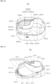
- the airflow guide may comprise a cylindrical duct coupling part into which the upper end of the connection duct part is inserted and coupled.
- the relative downward movement of the duct coupling part may be limited by a male screw thread.
- the relative movement limiter may comprise at least one of protruding ribs that are formed in a way that protrudes downward toward the male screw thread at the lower portion of the duct coupling part. At a time of the relative downward movement, the lower end surface of at least one of the protruding ribs may contact the male screw thread.
- a gap having a predetermined width may be formed between the lower end surface of at least one of the protruding ribs and the male screw thread.
- the relative downward movement may be limited to the predetermined width or less.
- At least one of the protruding ribs may comprise a first protruding rib, a second protruding rib and a third protruding rib that are arranged at regular intervals around a circular opening through which the upper end of the connection duct part passes.
- the heights at which the first protruding rib, the second protruding rib and the third protruding rib protrude downward from the lower portion of the duct coupling part may differ respectively.
- a maximum height of the first protruding rib protruding from the lower portion of the duct coupling part may be a first height
- a maximum height of the second protruding rib protruding from the lower portion of the duct coupling part may be a second height greater than the first height
- a maximum height of the third protruding rib protruding from the lower portion of the duct coupling part may be a third height greater than the second height.
- a circumferential width of the first protruding rib, a circumferential width of the second protruding rib and a circumferential width of the third protruding rib may be the same.
- the first protruding rib, the second protruding rib and the third protruding rib may be consecutively disposed clockwise at the lower end of the connection duct part.
- a lower end surface of the first protruding rib, a lower end surface of the second protruding rib and a lower end surface of the third protruding rib, protruding from the lower portion of the duct coupling part may be inclined surfaces the height of which respectively increases clockwise.
- the dry air supply part may further comprise a fastening nut disposed at the connection duct part.
- the fastening nut may be screw-coupled to the male screw thread of the connection duct part to fix the connection duct part to the lower surface of the tub. As the duct coupling part and the connection duct part are coupled completely, at least one of the protruding ribs may be in no contact with the fastening nut.
- a radial maximum width of at least one of the protruding ribs may be less than a gap between the outer circumferential surface of the connection duct part and the inner circumferential surface of the fastening nut.
- At least one of the protruding ribs may be inserted into the fastening nut.
- the duct coupling part may be coupled to the connection duct part, based on a two-stage coupling manipulation.
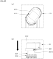
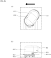
- the two-stage coupling manipulation may comprise a perpendicular movement manipulation of relatively moving the airflow guide downward; and a rotational movement manipulation of relatively moving the airflow guide circumferentially after the perpendicular movement manipulation is completed.
- the gap between the lower end surface of at least one of the protruding ribs and the male screw thread may decrease gradually.
- the airflow guide may rotate in a direction opposite to the direction in which the airflow guide rotates to screw-couple the fastening nut to the male screw thread of the connection duct part.
- the relative movement limiter may further comprise a first guide groove that is formed on the inner circumferential surface of the duct coupling part and extends linearly along an up-down direction.
- the relative movement limiter may further comprise a second guide groove that has one end portion integrally connecting to an upper end of the first guide groove and extends along a circumferential direction in a circular arc shape.
- the relative movement limiter may further comprise a guide projection may be provided on the outer circumferential surface of the connection duct part, protrudes toward the inner circumferential surface of the connection duct part, and moves along the first guide groove and the second guide groove at a time of the two-stage coupling manipulation.
- the perpendicular movement manipulation may be guided, and in the state in which the guide projection is inserted into the second guide groove, the rotational movement manipulation may be guided.
- a relative upward movement of the guide projection of the duct coupling part may be limited by the second guide groove.
- the lower end surface of the fastening nut may be exposed to the wash space at least partially.
- the fastening nut may comprise a plurality of contact projections extending from the lower end surface of the fastening nut.
- Each contact projection may have an upper end that respectively connects to the lower end surface of the fastening nut integrally, and having a lower end that extends toward the lower surface of the tub.
- Each of the plurality of contact projections may be space from each other on the lower end surface of the fastening nut along the circumferential direction at predetermined circumferential intervals.
- the predetermined circumferential interval of the plurality of contact projections may be maintained regularly.
- the predetermined circumferential interval may be greater than a maximum circumferential thickness of the plurality of contact projections.
- Each of the plurality of contact projections may have the same outer shape.
- Each of the plurality of contact projections may have an outer shape the horizontal cross section of which decreases gradually from the upper end to the lower end.
- each of the contact projections may be formed into a curved surface that is convex toward the lower surface of the tub.
- a dry air supply hole may be provided on the lower surface of the tub, and the upper end of the connection duct part may pass and extend through the dry air supply hole, and a ring-type coupling surface may be formed around the dry air supply hole and pressurized by the lower end of the contact projection.
- the coupling surface may extend in a direction perpendicular to the direction in which the fastening nut moves while being screw-coupled to the connection duct part.
- the direction in which the fastening nut moves while being screw-coupled to the connection duct part may be a perpendicular direction, and the direction in which the coupling surface extends may be a horizontal direction.
- a convergence surface having a predetermined downward inclination angle with respect to the horizontal direction may be provided around the coupling surface.
- a cylindrical part may be provided on the lower surface of the tub, and extend circumferentially along the dry air supply hole and protrude upward toward the lower end surface of the fastening nut.
- the height of the cylindrical part protruding from the lower surface of the tub may remain constant along the circumferential direction.
- the height of the cylindrical part protruding from the lower surface of the tub may be less than the height of the contact projection protruding from the lower end surface of the fastening nut.
- the airflow guide may be detachably coupled to the dry air supply part without an additional coupling member.
- the dry air supply part may comprise a connection duct part that extends in a way that penetrates the lower surface of the tub upward, and supplies the dry air to the airflow guide, and the airflow guide may be detachably coupled to the connection duct part.
- the airflow guide may be coupled to the connection duct part, based on a two-stage coupling manipulation.
- the two-stage coupling manipulation may comprise a perpendicular movement manipulation of relatively moving the airflow guide downward.
- the two-stage coupling manipulation may comprise a rotational movement manipulation of relatively moving the airflow guide circumferentially after the perpendicular movement manipulation is completed.
- the airflow guide may comprise a duct coupling part having an upper end that is exposed to an inner flow space, and a lower end that connects to the connection duct part, and having a cylindrical shape.
- the upper end of the cylindrical connection duct part may be coupled to the lower portion of the duct coupling part, based on the two-stage coupling manipulation.
- connection duct part may be inserted into the lower end of the duct coupling part.
- a first guide groove and a second guide groove may be formed on the inner circumferential surface of the duct coupling part, and the first guide groove may extend linearly along the up-down direction, and the second guide groove may have one end portion integrally connecting to the upper end of the first guide groove and extending along the circumferential direction in a circular arc shape.
- a guide projection may be provided on the outer circumferential surface of the connection duct part, and may protrude toward the inner circumferential surface of the connection duct part and join the first guide groove and the second guide groove.
- the perpendicular movement manipulation may be guided.
- the rotational movement manipulation may be guided.
- a stopper projection may be integrally provided at the second guide groove, and the stopper projection may be disposed near the other end portion of the second guide groove, and after the rotational movement manipulation is completed, block the generation of a relative rotation in a direction opposite to the direction of the rotational movement manipulation.
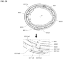
- the relative movement limiter may further comprise a release prevention part configured to restrict the airflow guide from rotating.
- the release prevention part may keep the airflow guide fixed after the rotational movement manipulation is completed.
- the release prevention part thus may prevent the airflow guide from rotating in a direction opposite to the direction of the rotational movement manipulation.
- One end portion of the release prevention part may be a fixed end portion that integrally connects to the airflow guide, and the other end portion of the release prevention part may be a free end portion that separates from the airflow guide and is elastically deformed.
- the dry air supply part may further comprise a fastening nut that is screw-coupled to the connection duct part and fixes the connection duct part to the tub, and at least one stopper may be integrally provided at the upper end of the fastening nut and join the free end portion of the release prevention part to prevent the airflow guide from rotating in a direction opposite to the direction of the rotational movement manipulation.
- the airflow guide may further comprise a release prevention part that keeps the airflow guide fixed after the rotational movement manipulation is completed.
- the release prevention part may prevent the airflow guide from rotating in a direction opposite to the direction of the rotational movement manipulation.
- the dry air supply part may comprise a connection duct part that extends in a way that penetrates the lower surface of the tub in the upward direction and supplies the dry air to the airflow guide, and the airflow guide may be detachably coupled to the connection duct part and prevented from rotating relative to the connection duct part in the opposite direction by the release prevention part.
- the airflow guide may comprise a lower guide which is coupled to the connection duct part and into which dry air generated in the dry air supply part is drawn; and an upper guide which is coupled to the upper side of the lower guide and has a flow space in which the dry air flows, the lower guide, comprising: a duct coupling part having an upper end that is exposed to the flow space and a lower end that is coupled to the connection duct part and having a cylindrical shape; and an edge wall that is formed in a way that surrounds the outer surface of the duct coupling part at least partially, and spaced from the duct coupling part, and the release prevention part may be integrally formed on the edge wall.
- the release prevention part may be formed in a way that the lower end of the edge wall is partially cut.
- one end portion of the release prevention part may be a fixed end portion that integrally connects to the airflow guide, and the other end portion of the release prevention part may be a free end portion that separates from the airflow guide and is elastically deformed.
- a radial thickness of the free end portion may be greater than a radial thickness of the fixed end portion.
- the dry air supply part may further comprise a fastening nut that is screw-coupled to the connection duct part and fixes the connection duct part to the tub, and at least one of stoppers may be integrally provided at the upper end of the fastening nut, and join the free end portion of the release prevention part and prevent the airflow guide from rotating in a direction opposite to the direction of the rotational movement manipulation.
- At least one of the stoppers may comprise a first stopper and a second stopper that are arranged one after another along the circumferential direction, and in the state in which the release prevention part is not elastically deformed, the free end portion may protrude at least partially further inward than the radial outer side end portion of the first stopper and the radial outer side end portion of the second stopper with respect to a radial direction.
- the free end portion may contact any one of one side surface of the first stopper or one side surface of the second stopper.
- the inner circumferential surface of the release prevention part, facing the connecting duct part, may extend toward the free end portion from the fixed end portion in the circumferential direction, and comprise a non-contact surface that is in no contact with the radial outer side end portion of the first stopper or the radial outer side end portion of the second stopper; and a contact surface that is formed after the non-contact surface in succession, and at a time of the rotational movement manipulation, contacts the radial outer side end portion of the first stopper or the radial outer side end portion of the second stopper.
- the free end portion of the release prevention part may be elastically deformed based on contact with the radial outer side end portion of the first stopper or the radial outer side end portion of the second stopper.
- a distance between the contact surface and the central axis of the duct coupling part may decrease gradually toward the free end portion.
- the free end portion of the release prevention part may be provided with an end portion surface that is formed in a parallel direction with the radial direction, and a tool groove may be provided on the end portion surface and concave toward the fixed end portion.
- At least one of reinforcement ribs may be integrally provided on the outer circumferential surface of the release prevention part, and protrude outward in the radial direction and extend along the circumferential direction.
- a dishwasher according to the present disclosure may have the effects of evenly distributing dry air and ensuring a sufficient period for which dry air stays in a tub, thereby improving drying efficiency and reducing a drying period.
- the dishwasher according to the present disclosure has the effect of preventing wash water from being reversely drawn through a discharge opening that is directly exposed to a wash space.
- the dishwasher according to the present disclosure has the effect of preventing an airflow guide from escaping from a set position or clattering through a simple structure after the airflow guide is assembled and fixed to a dry air supply part.
- the dishwasher according to the present disclosure has the effect of preventing the airflow guide from escaping from its right position or being broken due to an external impact after the airflow guide is assembled and fixed to the dry air supply part.
- the dishwasher according to the present disclosure has the effect of preventing the corrosion of the tub and a dry air supply hole and preventing the reproduction of germs and the generation of a bad smell between the tub and a fastening nut since the lower end surface of the fastening nut is exposed to a wash space to prevent wash water from remaining between the fastening nut and the tub.
- the dishwasher according to the present disclosure has the effect of simplifying the processes of assembling and fixing the airflow guide to the dry air supply part since the assembly structure and fixation structure of the airflow guide spraying dry air are simplified.
- the dishwasher according to the present disclosure has the effect of preventing a change in a predetermined position of a discharge opening through a means of preventing the misassemble between an upper guide and a lower guide that constitute the airflow guide.
- the dishwasher according to the present disclosure has the effect of preventing the airflow guide from releasing or escaping from its set position through a simple structure after the airflow guide is assembled and fixed to the dry air supply part.
- a dishwasher comprises: a tub that defines a wash space configured to accommodate a wash target, the tub having a front surface that is open; a dry air supply part configured to generate dry air for drying the wash target; and an airflow guide configured to guide the dry air generated by the dry air supply part to the wash space, the dry air supply part comprises a connection duct part that passes through a surface of the tub, the connection duct part being coupled to the airflow guide and configured to supply the dry air into the airflow guide, and wherein the dry air supply further comprises a fastening nut that is screw-coupled to the connection duct, and wherein the fastening nut comprises a plurality of contact projections that extend from the lower end surface of the fastening nut toward the surface of the tub.
- first means a first component, a second component, unless stated to the contrary.
- each component can be provided as a single one or a plurality of ones, unless explicitly stated to the contrary.
- one component When one component is described as being “in the upper portion (or lower potion)" or “on (or under)” another component, one component can be directly on (or under) another component, and an additional component can be interposed between the two components.
- any one component can be directly connected or coupled to another component, but an additional component can be “interposed” between the two components or the two components can be “connected”, “coupled”, or “connected” by an additional component.
- a and/or B as used herein can denote A, B or A and B, and the terms “C to D” can denote C or greater and D or less, unless stated to the contrary.
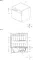
- FIG. 1 is a front perspective view showing a dishwasher according to the present disclosure
- FIG. 2 is a schematic cross-sectional view schematically showing the inner structure of the dishwasher according to the present disclosure.
- the dishwasher 1 comprises a case 10 forming the exterior of the dishwasher 1, a tub 20 being installed in the case 10, forming a wash space 21 in which a wash target is washed and having a front surface that is open, a door 30 opening and closing the open front surface of the tub 20, a driving part 40 being disposed under the tub 20 and supplying, collecting, circulating and draining wash water for washing a wash target, a storage part 50 being provided detachably in the wash space 21 in the tub 20 and allowing a wash target to be mounted on, and a spray part 60 being installed near the storage part 50 and spraying wash water for washing a wash target.
- wash targets mounted in the storage part 50 may be cooking vessels such as bowls, dishes, spoons, chopsticks, and the like, and other cooking tools, for example.
- the wash targets are referred to as cooking vessels, unless mentioned otherwise.
- the tub 20 may be formed into a box the front surface of which is open entirely, and may be a so-called tub.
- the tub 20 may have a wash space 21 therein, and its open front surface may be opened and closed by the door 30.
- the tub 20 may be formed in a way that a metallic sheet having strong resistance against high-temperature and moisture, e.g., a stainless steel-based sheet, is pressed.
- a metallic sheet having strong resistance against high-temperature and moisture e.g., a stainless steel-based sheet
- a plurality of brackets may be disposed on the inner surfaces of the tub 20 and allow functional components such as a storage part 50, a spray part 60 and the like, which are described below, to be supported and installed in the tub 20.
- the driving part 40 may comprise a sump 41 storing wash water, a sump cover 42 distinguishing the sump 41 from the tub 20, a water supply part 43 supplying wash water to the sump 41 from the outside, a drain part 44 discharging wash water of the sump 41 to the outside, and a water supply pump 45 and a supply channel 46 for supplying wash water of the sump 41 to the spray part 60.
- the sump cover 42 may be disposed at the upper side of the sump 41, and distinguish the sump 41 from the tub 20. Additionally, the sump cover 42 may be provided with a plurality of return holes for returning wash water, having sprayed to the wash space 21 through the spray part 60, to the sump 41.
- wash water having sprayed toward cooking vessels from the spray part 60 may fall to the lower portion of the wash space 21 and return to the sump 41 through the sump cover 42.
- the water supply pump 45 is provided in a lateral portion or the lower portion of the sump 41, and pressurizes wash water and supplies the same to the spray part 60.
- the water supply pump 45 may connect to the sump 41, and the other end may connect to the supply channel 46.
- the water supply pump 45 may have an impeller 451, a motor 453 and the like, therein. As power is supplied to the motor 453, the impeller 451 may rotate, and wash water of the sump 41 may be pressurized and then supplied to the spray part 60 through the supply channel 46.
- the supply channel 46 may selectively supply the wash water supplied by the water supply pump 45 to the spray part 60.
- the supply channel 46 may comprise a first supply channel 461 connecting to a lower spray arm 61, and a second supply channel 463 connecting to an upper spray arm 62 and a top nozzle 63.
- the supply channel 46 may be provided with a supply channel diverting valve 465 selectively opening and closing the supply channels 461, 463.
- the supply channel diverting valve 465 may be controlled to allow each of the supply channels 461, 463 to be opened consecutively or opened simultaneously.
- the spray part 60 is provided to spray wash water to cooking vessels and the like stored in the storage part 50.
- the spray part 60 may comprise a lower spray arm 61 being disposed under the tub 20 and spraying wash water to a lower rack 51, an upper spray arm 62 being disposed between the lower rack 51 and an upper rack 52 and spraying wash water to the lower rack 51 and the upper rack 52, and a top nozzle 63 being disposed in the upper portion of the tub 20 and spraying wash water to a top rack 53 or the upper rack 52.
- the lower spray arm 61 and the upper spray arm 62 may be provided in the wash space 21 of the tub 20, and spray wash water toward cooking vessels in the storage part 50 while rotating.
- the lower spray arm 61 may be rotatably supported at the upper side of the sump cover 42 such that the lower spray arm 61 may spray wash water to the lower rack 51 while rotating under the lower rack 51.
- the upper spray arm 62 may be rotatably supported by a spray arm holder 467 such that the upper spray arm 62 may spray wash water while rotating between the lower rack 51 and the upper rack 52.
- the tub 20 may be further provided with a reflection plate on a lower surface 25 thereof, to enhance washing efficiency, and the reflection plate diverts the direction of wash water having sprayed from the lower spray arm 61 to an upward direction (U-direction).
- the storage part 50 for storing cooking vessels may be provided in the wash space 21.
- the storage part 50 may be withdrawn through the open front surface of the tub 20 from the inside of the tub 20.
- FIG. 2 shows an embodiment provided with a storage part comprising a lower rack 51 that is disposed in the lower portion of the tub 20 and stores relatively large-sized cooking vessels, an upper rack 52 that is disposed at the upper side of the lower rack 51 and stores medium-sized cooking vessels, and a top rack 53 that is disposed in the upper portion of the tub 20 and stores small-sized cooking vessels and the like.
- a dishwasher that is provided with three storage parts 50, as illustrated, is described.
- Each of the lower rack 51, the upper rack 52 and the top rack 53 may be withdrawn outward through the open front surface of the tub 20.
- the tub 20 may have a guide rail 54, on both lateral walls thereof that form the inner circumferential surface of the tub 20, and for example, the guide rail 54 may comprise an upper rail 541, a lower rail 542, a top rail 543 and the like.
- Each of the lower rack 51, the upper rack 52 and the top rack 53 may be provided thereunder with wheels. A user may withdraw the lower rack 51, the upper rack 52 and the top rack 53 outward through the front surface of the tub 20 to easily store cooking vessels on the racks or take out cooking vessels from the racks after a washing process.
- the guide rail 54 may be provided as a fixed guide rail that guides the withdrawal and insertion of the spray part 60 in the form of a simple rail or as a stretchable guide rail which guides the withdrawal and storage of the spray part 60 and the withdrawal distance of which increases as the spray part 60 is withdrawn.
- the door 30 is used for opening and closing the open front surface of the tub 20 that is described above.
- a hinge part for opening and closing the door 30 is provided in the lower portion of the open front surface, and the door 30 is open with respect to the hinge part as a rotation axis.
- the door 30 may be provided with a handle 31 and a control panel 32 on the outer surface thereof.
- the handle 31 is used for opening the door 30, and the control panel 32 is used for controlling the dishwasher 1.
- control panel 32 may be provided with a display 33 that visually displays information on a current operation state and the like of the dishwasher, and a button part 34 comprising a selection button to which the user's selection manipulation is input, a power button to which the user's manipulation for turning on-off the power source of the dishwasher is input, and the like.
- the inner surface of the door 30 may form a mounting surface that supports the lower rack 51 of the storage part 50 as the door 30 is opened as well as forming one surface of the tub 20 as the door 30 is closed.
- the inner surface of the door 30 forms a horizontal surface in the same direction where the guide rail 54, by which the lower rack 51 is guided, extends, for example.
- the door 30 may be provided rotatably between a closed position and a fully-open position, and an intermediate still position may be formed between the closed position and the fully open position.
- the door 30 may stand still in the intermediate still position, and at this time, the wash space 21 of the tub 20 may be open outward partially.
- a dry air supply part 80 described hereafter may operate to supply high-temperature dry air or low-temperature dry air to the wash space 21.
- the dry air supply part 80 may be provided in the lower portion of the tub 20 and generate high-temperature dry air and supply the high-temperature dry air into the tub 20.
- the dry air supply part 80 may be accommodated in a base 90 and may be disposed to be supported by a lower surface 91 of the base 90.
- the dry air supply part 80 may be disposed in a position adjacent to a rear surface 93 of the base 90, and disposed in a position between a leakage detecting part and the rear surface 93 of the base 90, approximately in parallel with the rear surface 93 of the base 90.
- the position in which the dry air supply part is disposed may be selected considering the characteristics of the dry air supply part 80 that generates heat of about 100°C or greater in a high-temperature dry air supply mode. That is, the dry air supply part may be disposed to avoid electronic components that are greatly affected by high-temperature heat.
- the arrangement position of the dry air supply part may be selected based on the position of a dry air supply hole 254 formed on the lower surface 25 of the tub 20. That is, considering the user's safety, the dry air supply hole 254 into which dry air flows may be formed at the corner of the lower surface 25 of the tub 20, which is adjacent to the rear surface and the left side surface of the tub 20.
- the dry air supply part 80 may be disposed at the lower side of the dry air supply hole 254.
- the arrangement position of the dry air supply part 80 is described exemplarily.
- the dry air supply part 80 may be disposed near a left side surface 94, a right side surface 95 or a front surface 92 of the base 90 rather than the rear surface 93 of the base 90.
- the dry air supply part 80 disposed near the rear surface 93 of the base 90 approximately in parallel with the rear surface 93 is described, but the position of the dry air supply part 80 is not limited.
- a support rib for supporting the dry air supply part 80 and preventing the escape of the dry air supply part 80 may be provided on the lower surface 91 of the base 90.
- the support rib, the guide ribs and the wash water rib may be formed integrally on the lower surface 91 of the base 90, for example.
- a first leg, a second leg 892 and a third leg 893 of the dry air supply part 80 described hereafter may be coupled to the support rib, based on a non-fastening method. That is, the first leg, the second leg 892 and the third leg 893 may be simply held at the support rib without an additional fastening means such that the dry air supply part 80 may be supported in up-down, front-rear and left-right directions.
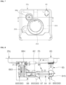
- FIG. 4 shows a detailed configuration of the dry air supply part 80.
- the dry air supply part 80 generating dry air and supplying the same into the tub 20 may comprise an air blowing fan that generates dry airflow F to be supplied into the tub 20, a heater that heats dry air, a heater housing 81 that has an air passage in which the heater is accommodated, and a filtering part 88 that filters air to be suctioned into the air blowing fan.
- the air blowing fan is disposed at the upstream side in the direction of dry airflow F with respect to the heater and the heater housing 81, and accelerates air to the air passage formed in the heater housing 81 to generate dry airflow F.
- the air blowing fan, and an air blowing motor generating rotational driving force of the air blowing fan may be mutually modularized, and form an assembly in a way that the air blowing fan and the air blowing motor are accommodated in a fan housing 82.
- the air blowing fan and the fan housing 82 may be fixed to a housing connector 87 that connects a filer housing 881 of the below-described filtering part 88 and the heater housing 81.
- the air blowing fan and the fan housing 82 may be accommodated entirely in the filter housing 881 in the state of being fixed to a connection tab 872 the housing connector 87.
- the type of the air blowing fan to be applied to the dry air supply part 80 is not limited, but a sirocco fan, for example, is preferred considering the position and space limitations in the installation of the air blowing fan.
- filtered air may be suctioned from a lower surface of the fan housing 82, in a direction parallel a direction from the center of the sirocco fan to the rotational axis of the same, and be accelerated and discharged outward in the radial direction.
- the accelerated and discharged air may form dry airflow F and be drawn into the air passage in the heater housing 81 through the fan housing 82 and an inlet 8712 of the housing connector 97.
- the air blowing fan e.g., a sirocco fan
- a rotation shaft 8251 of the motor may be disposed to have directionality approximately parallel with the up-down direction (U-D direction), and filtered air may be suctioned through the lower surface of the fan housing 82, for example.
- a PCB substrate for controlling the moor may be built into an upper surface 821 of the fan housing 82, which corresponds to the opposite side of the lower surface into which filtered air is suctioned.
- the fan housing 82 may be fixed to a ring-type connection tab 872 provided at the housing connector 87 through a fastening means such as a screw bolt that is not illustrated, and the like, for example.
- connection tab 872 may be provided with a pair of fastening bosses that extend from the upper surface of the connection tab 872 in the upward direction (U-direction).
- the first leg protruding toward the base may be integrally formed under the housing connector 87.
- the heater may be indirectly supported in the state of separating from the heater housing 81 and a connector main body 871.
- the front end side of the heater may be supported by a terminal fixation part, in the state of separating from the housing connector 87.
- a c may be fixed to the front surface of the terminal fixation part, in the state of protruding outward.
- An entirely-open rear end portion 871b of the housing connector 87 may be fixed while being fitted and coupled to the heater housing 81.
- the heater is disposed in the air passage formed in the heater housing 81, and preferably, is directly exposed to dry airflow F in the air passage and heats the dry airflow F.
- the dry air supply part 80 supplies high-temperature dry air
- power may be supplied to the heater, and the heater may heat dry air
- the dry air supply part 80 supplies low-temperature dry air
- the supply of power to the heater may be cut off, and the heater may stop operating.
- the air blowing motor may keep operating to generate dry airflow F.
- the type of the heater provided in the dry air supply part 80 of one embodiment is not limited, but a tube-type sheath heater may be selected since the sheath heater has a relatively simple structure, ensures excellent heat generation efficiency and helps to prevent electric leakage caused by the reverse inflow of wash water that comes in from the tub 20 reversely, for example.
- the heater that is a sheath heater may have a stereoscopic shape with a plurality of bends, to be directly exposed to dry airflow F at the air passage in the heater housing 81 and ensure a maximum heat transfer surface.
- a pair of terminals for receiving power may be formed in one end portion and the other end portion of the heater.
- the rear end side of the heater may be fixed and supported by a single heater bracket 845 disposed in the heater housing 81. That is, the rear end side of the heater may be supported on the air passage through the heater bracket 845 in the state of being separated from the heater housing 81.
- a temperature sensor as a temperature sensing part 86 sensing the temperature of high-temperature dry air generated through the heater or detecting the overheating of the heater may be provided on the upper side surface of the heater housing 81.
- the temperature sensor may comprise a thermistor that senses the temperature of dry air, and a thermostat that detects the overheating of the heater.
- An output signal of the temperature sensor may be delivered to a non-illustrated controller, and the controller may receive the output signal of the temperature sensor to determine the temperature of high-temperature dry air and the overheating of the heater. As the heater overheats, the controller may cut off the supply of power to the heater and change the operation mode of the dry air supply part 80 from the high-temperature dry air supply mode to the low-temperature dry air supply mode.
- the heater housing 81 may be formed into a hollow hole that has a vacant inner space such that the air passage, in which the above-described heater and heater bracket 845 are disposed, is formed.
- the front end portion of the heater housing 81 corresponding to the upper stream side with respect to the direction of the movement of the dry airflow F, and the rear end portion of the heater housing 81, corresponding to the lower stream side with respect to the direction of the movement of the dry airflow F, may be open at least partially.
- the dry air supply part 80 may further comprise a connection duct part 85 that is coupled to an outlet, formed at the left end side of the heater housing 81 and being open in the upward direction (U-direction), and has an air passage therein.
- the heater housing 81 and the air blowing fan are disposed under the lower surface 25 of the tub 20, e.g., a bottom tub 20c.
- the connection duct part 85 guides dry air being discharged from the heater housing 81 to a predetermined position, i.e., the dry air supply hole 254 formed at the tub 20.
- the predetermined position may be the lower surface 25 of the tub 20, and the dry air supply hole 254 into which dry airflow F guided to the connection duct part 85 is drawn may be formed at a corner of the lower surface 25 of the tub 20, which is adjacent to a rear surface 23 and a left side surface 26.
- a duct main body 851 of the connection duct part 85 may have a shape that is capable of changing the direction of dry airflow and connecting the dry air supply hole 254 of the tub 20 and the outlet of the heater housing 81.
- the duct main body 851 of the connection duct part 85 may have a cylinder shape that allows of the fluid communication of a lower end portion 8512 with the outlet of the heater housing 81 and allows an upper end 8511 to extend in the upward direction (U-direction) and connect to the dry air supply hole 254.
- the lower end portion 8512 of the duct main body 851 may be coupled the heater housing 81 in a sliding manner.
- the lower end portion of the duct main body 851 may have a rectangle pillar shape, and for the prevention of leakage, the upper end 8511 of the duct main body 851 may have a cylinder shape.
- the duct main body 851 may have a cylinder shape to improve the efficiency of a coupling between the upper end 8511 of the duct main body 851 and the dry air supply hole 254 of the tub 20 and to prevent leakage.
- An airflow guide 83 may be coupled to the upper end 8511 of the duct main body 851 and divert the direction of dry airflow being supplied through the duct main body 851 to supply the dry airflow to the wash space.
- the filtering part 88 may be disposed in the upper stream of the heater with respect to the direction of the flow of dry airflow, to filter air to be suctioned into the air blowing fan and supply the filtered air to the heater.
- the filtering part 88 may comprise a filter member 883 that filters air to be suctioned into the air blowing fan, and a hollow hole-type filter housing 881 that has a filter accommodation space S1 in which the filter member 883 is disposed in a replaceable manner and a fan housing accommodation space S2 in which the fan housing 82 is disposed.
- the filter housing 881 may comprise a first housing 8811 and a second housing 8812 that are disposed in the form of a segment body that is segmented with respect to the up-down direction (U-D direction), for example.
- the first housing 8811 may be the upper housing
- the second housing 8812 may be the lower housing.
- the filter housing 881 accommodates and supports the filter member 883 and the fan housing 82 of the air blowing fan.
- the first housing 8811 may be divided into a filter accommodation part 8811a and a fan housing accommodation part 8811b such that the first housing 8811 accommodates and supports the filter member 883 and the fan housing 82 at least partially, preferably, accommodates and supports the upper portion of the filter member 883 and the upper portion of the fan housing 82.
- the lower surfaces of the filter accommodation part 8811a and the fan housing accommodation part 8811b of the first housing 8811 are open entirely to allow the second housing 8812 to be coupled to the lower sides of the filter accommodation part 8811a and the fan housing accommodation part 8811b of the first housing 8811.
- the filter accommodation part 8811a may be formed further upstream than the fan housing accommodation part 8811b with respect to the direction of the flow of dry airflow, and in the illustrative embodiment, formed on the right of the fan housing accommodation part 8811b.
- the filter accommodation part 8811a may have an outer shape of a partial cylinder to accommodate the filter member 883 having a cylinder shape in a way that the filter member 883 may be inserted and withdrawn when the filter member 883 is replaced.
- a filter guide rib may be integrally provided in the filter accommodation part 8811a and have a shape similar to that of a filter guide rib 8812f of the second housing 8812 described hereafter.
- the filter accommodation part 8811a may have a coupling opening 8811c at the upper end thereof, and the coupling opening 8811c is open in the form of a circle in response to the outer shape of the filter member 883.
- the filter member 883 may move downward through the coupling opening 8811c, and move to a filter accommodation part 8812a of the second housing 8812.
- the fan housing accommodation part 8811b may be formed further downstream than the filter accommodation part 8811a with respect to the direction of the flow of dry airflow, and in the illustrative embodiment, formed integrally at the filter accommodation part 8811a, on the right of the filter accommodation part 8811a, near the heater housing 81.
- the fan housing accommodation part 8811b may have an inner shape corresponding to the outer shape of the upper portion of the fan housing 82, to cover the upper portion of the air blowing fan entirely.
- the fan housing accommodation part 8811b may have an upper surface formed into a flat plate.
- the upper surface of the first housing 8811 may have an inclined surface 8811b1 that connects the upper end of the filter accommodation part 8811a and the fan housing accommodation part 8811b.
- the second housing 8812 of the filter housing 881 is coupled to the lower portion of the first housing 8811 and forms a sealed accommodation space, and accommodates and supports the lower portions of the filter member 883 and the fan housing 82.
- the second housing 8812 may be divided into a filter accommodation part 8812a and a fan housing accommodation part 8812b, to accommodate and support the lower portion of the filter member 883 and the lower portion of the fan housing 82.
- the upper end of the second housing 8812 may be open entirely to be coupled to the lower end of the first housing 8811.
- the filter accommodation part 8812a of the second housing 8812 may be provided with a plurality of filter guide ribs that guides the filter member 883's movement and prevents the filter member 883's escape from the right position at a time of inserting the filter member 883.
- the plurality of filter guide ribs may be arranged and disposed radially around the filter member 883.
- a lower suction opening 8812c may be formed on the bottom surface of the filter accommodation part 8812a in a penetrating manner, and is open toward the lower surface of the base 90 and allows external air to be suctioned.
- the lower suction opening 8812c may have a circle shape to correspond to the shape of a lower opening of the filter member 883 having a cylinder shape, and a relative position and size of the lower suction opening 8812c may be determined to allow external air to pass through the lower opening and to be smoothly suctioned into the filter member 883.
- a pair of ring-type ribs may be formed around the lower suction opening of the bottom surface of the second housing 8812, and prevent non-filtered external air to be leaked and suctioned into the inner space of the filter housing 881 directly.
- the fan housing accommodation part 8812b may be formed further downstream than the filter accommodation part 8812a with respect to the direction of the flow of dry airflow, and in the illustrative embodiment, formed integrally at the filter accommodation part 8812a, on the right of the filter accommodation part 8812a, near the heater housing 81.
- the fan housing accommodation part 8811b may have an inner shape corresponding to the outer shape of the lower portion of the fan housing 82, to cover the lower portion of the air blowing fan entirely.
- the bottom surface of the fan housing accommodation part 8811b may be spaced a predetermined distance apart from the lower surface of the fan housing 82, to allow filtered air to be suctioned effectively, and for example, be formed into a flat surface in a direction parallel with the horizontal direction.
- a plurality of uplifted surface parts and a screw boss that protrude from the bottom surface may be provided in the fan housing accommodation part 8812b.
- first housing 8811 and the second housing 8812 that are disposed in the form of a segment body as described above, the lower end of the first housing 8811 and the upper end of the second housing 8812 may be detachably coupled to each other.
- a fastening tab 8811d extending toward the second housing 8812 is provided at the lower end of the first housing 8811, and a hook projection 8812d may be provided at the upper end of the second housing 8812 and fastened to the fastening tab 8811d based on a hook coupling.
- a tub connection duct 882 may be detachably coupled and fastened to the coupling opening 8811c of the filter accommodation part 8811a of the first housing 8811.
- the filter member 883 may be replaced through a lower surface 25 of the tub 20.
- the filter accommodation part 8811a of the first housing 8811 needs to connect to the lower surface 25 of the tub 20, and the tub connection duct 882 connects the lower surface 25 of the tub 20 and the filter accommodation part 8811a of the first housing 8811.
- the tub connection duct 882 may be integrally provided at the filter accommodation part 8811a of the first housing 8811.
- the tub connection duct 882 may be provided additionally in the first housing 8811, as illustrated.
- an upper end portion 8821 of the tub connection duct 882 may pass through the lower surface 25 of the tub 20 and extend upward.
- a filter replacement hole 253 may be provided on the lower surface 25 of the tub 20 to allow the upper end portion 8821 of the tub connection duct 882 to be inserted.
- a sump hole 252 on which a sump 41 is mounted may be provided in the central portion of the lower surface 25 of the tub 20.
- the lower surface 25 of the tub 20 may have a convergence surface having an inclination angle at which the convergence surface gradually inclines downward toward the sump hole 252, to allow wash water to be effectively converged on the sump hole 252.
- the filter replacement hole 253 may be formed on the convergence surface, at the rear of the sump hole 252.
- the filter replacement hole 253 may be formed at the corner adjacent to the rear surface and the right side surface, on the lower surface 25 of the tub 20. Additionally, to easily insert and withdraw the filter member 883 for replacement, the filter replacement hole 253 may be disposed closer to the front surface of the tub 20 than the dry air supply hole 254 and disposed further rearward than a water softener communication hole 255.
- the water softener communication hole 255 formed in front of the filter replacement hole 253, for example, may be used to insert a water softening agent into a water softener provided under the water softener communication hole 255, and the like, or used for the replacement and maintenance and repairs of another component such as a purification filter of a water supply part, and the like.
- the filter replacement hole 253 may be disposed between the water softener communication hole 255 and the dry air supply hole 254 with respect to the front-rear direction or the left-right direction.
- the filter replacement hole 253 may be disposed outside a virtual extension line that connects the water softener communication hole 255 and the dry air supply hole 254.
- the strength, torsional rigidity and flexural rigidity of the tub 20 may not decrease.
- a sealing cap 884 having a different shape or color from the water softener communication hole 255 may be applied at the upper end of the tub connection duct 882 that passes through the filter replacement hole 253 and is exposed to the wash space.
- the filter replacement hole 253 is provided on the convergence surface provided on the lower surface 25 of the tub 20.
- the tub connection duct 882's upper end portion and flange coupled to the filter replacement hole 253 may have a predetermined inclination angle with respect to the perpendicular direction in response to the inclination angle of the convergence surface of the tub 20, i.e., may be formed to incline with respect to the perpendicular direction.
- a first gasket 885 may be further provided between the flange 8823 of the tub connection duct 882 and the lower surface 25 of the tub 20, to prevent a fastening nut 886 from loosening and prevent leakage.
- the sealing cap 884 may be coupled to the upper end portion 8821 of the tub connection duct 882 exposed to the inside of the tub 20.
- an airtight ring 887 for preventing leakage may be disposed between the sealing cap 884 and the upper end portion 8821 of the tub connection duct 882.
- an upper suction opening 8826 into which external air is suctioned may be formed under the flange corresponding to the upper side of the filter accommodation space S1, between the upper end portion and a lower end portion of the tub connection duct 882, in a penetrating manner.
- the upper suction opening 8826 may be formed in a way that penetrates the cylinder-type tub connection duct 882 from the inner circumferential surface thereof to the outer circumferential surface thereof.
- the upper suction opening 8826 may be provided as a plurality of penetration openings arranged and formed along the circumferential direction of the tub connection duct 882.
- the upper suction opening 8826 may be formed higher than an upper opening of the filter member 883, in the state where the filter member 883 is disposed in the filter accommodation space S1. Accordingly, the upper suction opening 8826 may be formed between the tub 20 and the upper surface of the filter member 883 with respect to the up-down direction.
- the first housing 8811 and the second housing 8812 of the filter housing 881 of the dishwasher 1 of one embodiment are spaced from each other in the up-down direction, and in the filter housing 881, external air is suctioned through a plurality of suction openings that are open toward a space between the base 90 and the tub 20.
- the plurality of suction openings may comprise the upper suction opening 8826 provided at the tub connection duct 882, at the upper side of the filter accommodation space S1, and the lower suction opening 8812c provided on the bottom surface of the second housing 8812, at the lower side of the filter accommodation space S1.
- the upper suction opening 8826 and the lower suction opening 8812c are spaced from each other and disposed respectively in the uppermost position and the lowermost position of the filter housing 881 with respect to the space between the tub 20 and the base 90. Accordingly, in the state where the effect of the flow rate of air suctioned respectively into the upper suction opening and the lower suction opening is minimized, external air may flow into the filter housing 881 through the two suction openings, thereby ensuring more flow rate of air required to dry a wash target and spending less time drying a wash target than usual.
- the upper suction opening 8826 is open in a direction approximately parallel with the horizontal direction. Accordingly, external air suctioned into the upper suction opening 8826 forms airflow of a direction parallel with the horizontal direction.
- the lower suction opening 8812c is formed on the bottom surface that extends horizontally. Accordingly, the lower suction opening 8812c is open toward the base 90 in a direction parallel with the perpendicular direction, and external air suctioned into the lower suction opening 8812c forms airflow of a direction parallel with the perpendicular direction.
- External air suctioned through the upper suction opening 8826 may enter into the upper opening of the filter member 883 disposed right under the upper suction opening 8826 in the state where the filter member 883 is disposed in the filter accommodation space S1.
- external air suctioned through the lower suction opening 8812c may enter into the lower opening of the filter member 883 disposed right on the lower suction opening 8812c in the state where the filter member 883 is disposed in the filter accommodation space S1.
- an airtight means of preventing non-filtered air from being suctioned into the filter housing 881 may be provided at the upper end side and the lower end side of the filter member 883.
- the upper opening of the filter member 883 is open toward the lower surface 25 of the tub 20, and the lower opening of the filter member 883 is open toward the lower surface of the base 90. Accordingly, the direction of airflow of external air changes downward while passing through the upper opening, and external air having passed through the lower opening flows upward.
- external air suctioned into the filter member 883 may pass through the filtering material of the filter member 883 and be evenly suctioned entirely in the up-down direction and circumferential direction.
- the direction of the flow of the filtered air having passed through the outer circumferential surface of the filter member 883 may change toward the lower surface of the fan housing 82 that is open toward the bottom surface of the filter housing 881.
- the lower surface of the fan housing 82 is disposed in a position spaced upward from the bottom surface, between the lower end and the upper end of the filter member 883. Accordingly, air having passed through the filter member 883 in a position higher than the lower surface of the fan housing 82 flows downward to the lower surface of the fan housing 82, and air having passed through the filter member 883 in a position lower than the lower surface of the fan housing 82 flows upward to the lower surface of the fan housing 82.
- Filtered air drawn into the fan housing 82 through the above-described flow path is accelerated by the air blowing fan and then drawn into the housing connector 87 and the inner space of the heater housing 81, such that dry airflow F is formed.
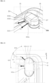
- the airflow guide 83 may be disposed between the lower surface 25 of the bottom tub 20c and the lower rack 51, near the lower surface 25 of the bottom tub 20c, and divert the direction of the flow of dry airflow F supplied through the duct main body 851.
- the airflow guide 83 may be disposed near the corner formed between the left side surface 26 and the rear surface 23 of the bottom tub 20c or near the corner formed between the right side surface 27 and the rear surface 23 of the bottom tub 20c.
- the above-described dry air supply hole 254 for transferring dry air may be formed on the lower surface 25 of the bottom tub 20c.
- FIGS. 1 to 9 show that the airflow guide 83 and the dry air supply hole 254 are adjacent to the lower surface 25 of the bottom tub 20c, near the corner formed between the left side surface 26 and the rear surface 23 of the bottom tub 20c, for example.
- the airflow guide 83 and the dry air supply hole 254, which are disposed near the corner formed between the left side surface 26 and the rear surface 23 of the bottom tub 20c as illustrated, are described as an example, but not limited.
- the corner formed between the left side surface 26 and the rear surface 23 of the bottom tub 20c corresponds to a position farthest from the upper end of the front surface 22 of the tub 20 that is partially open in the drying stage.
- the period for which dry air sprayed from the airflow guide 83 remains in the tub 20 may extend effectively.
- dry air may be supplied to the lower rack 51, the upper rack 52 and the top rack 53 evenly and then discharged through the upper end of the front surface of the tub, enabling thermal energy of the dry air to be transferred to wash targets effectively and significantly promoting the effect of drying the wash targets.
- the airflow guide 83 is spaced a predetermined distance apart from the rear surface 23, the lower surface 25 and the left side surface 26 of the bottom tub 20c, food and the like may be effectively prevented from being fitted and fixed between the airflow guide 83 and the bottom tub 20c.
- the period for which dry air remains in the tub 20 may further increase, based on the adjustment of the direction of the spray of dry air from the airflow guide 83.
- a discharge opening 833 of the airflow guide 83 from which dry air sprays, may be formed in a position where dry air does not directly spray toward the lower rack 51 and wash targets stored on the lower rack 51.
- the airflow guide 83 of the dishwasher 1 of one embodiment may discharge dry air in a direction that is not the upward direction (U-direction) perpendicular to the lower surface 25 of the bottom tub 20c or the direction in which dry air does not spray directly toward the lower rack 51.
- the discharge opening 833 from which dry air sprays may be formed on the right side surface of the airflow guide 83 to discharge dry air in a direction approximately parallel with the rear surface 23 of the bottom tub 20c.
- the front-rear (F-R direction) width of the airflow guide 83 may be greater than the left-right (Le-Ri direction) width in the state where the airflow guide 83 is coupled to the duct main body 851 of the connection duct part 85, and the discharge opening 833 may be formed continuously throughout the right side surface of the airflow guide 83, facing the right side surface 27 of the bottom tub 20c, and the rear surface of the airflow guide 83. That is, the discharge opening 833 of the airflow guide 83 may have the directionality that does not face the door directly and face the front surface 22 of the tub 22 or the door 30 linearly.
- the discharge opening 833 of the airflow guide 83 may be formed into a slit or have an oblong shape the up-down (U-D direction) height of which is less than the front-rear (F-R direction) length. Additionally, for dry air to spray in a lowermost position, the up-down (U-D direction) height of the discharge opening 833 may remain constant in the front-rear direction (F-R direction).
- a front edge 833b of the discharge opening 833 which is a first side edge, may be formed on the right side surface of the airflow guide 83, having a flat plate shape, and a rear edge 833a that is a second side edge may extend to the rear surface of the airflow guide 83, having a curved surface shape. That is, the front edge 833b and the rear edge 833a of the discharge opening 833 may be spaced from each other, along the direction where an upper end edge of the discharge opening 833 extends.
- dry air sprayed through the discharge opening 833 may be discharged in the lowest position with respect to the up-down direction (U-D direction), and based on the slit shape of the discharge opening, spray having directionality, which is approximately parallel with the rear surface 23 of the bottom tub 20c with respect to the horizontal direction and does not face the door 30 linearly.
- the discharge opening 833 may extend from the lower portion of the lower rack 51, between a space S formed between the lower rack 51 and the rear surface 23 of the bottom tub 20c.
- At least a portion of dry air sprayed through the slit-shaped discharge opening 833 may spray toward between the lower surface 25 of the bottom tub 20c and the lower rack 51, and the remaining portion of the dry air may spray toward the space S.
- the front edge 833a of the slit-shaped discharge opening 833 may be disposed under the lower rack 51, and the rear edge 833b of the discharge opening 833 may be disposed in the space S.
- the discharge opening 833 of the airflow guide 83 may be divided into a first portion 8331 disposed under the lower rack 51, and a second portion 8332 disposed in the space S, and a rear end portion 511 of the lower rack 51 may be a reference line dividing the first portion 8331 and the second portion 8332.
- dry air may spray in a direction that does not face the center of the lower rack 51 directly, or a direction that avoids the lower rack 51, and dry airflow F having passed through the first portion 8331 may move up toward the lower surface of the lower rack 51, and dry airflow F having passed through the second portion 8332 may move up by passing through the space S.
- the thermal energy of dry air may be distributed evenly in the tub 20 without concentrating on a specific portion of the lower rack 51.
- a relative ratio of the first portion 8331 and the second portion 8332 may be set differently depending on a required distribution ratio of dry air. That is, when more dry air needs to be supplied to the lower rack 51, a surface area ratio of the first portion 8331 may increase, and when more dry air needs to be supplied to the space S, a surface area ratio of the second portion 8332 may increase.
- the surface area ratio of the first portion 8331 is greater than the surface area ratio of the second portion 8332, for example.
- the airflow guide 83 may be disposed closer to the rear surface 23 of the bottom tub 20c than the lower rack 51. Specifically, when the rear end portion 511 of the lower rack 51 is spaced a first distance G1 apart from the rear surface 23 of the bottom tub 20c in the state where the lower rack 51 is stored in the wash space, the rear end portion of the airflow guide 83 may be spaced from the rear surface 23 of the bottom tub 20c to have a second distance G2 less than the first distance G1.
- the front edge 833a of the slit-shaped discharge opening 833 may be disposed under the lower rack 51, and the rear edge 833b of the discharge opening 833 may be disposed in the space S.
- the discharge opening 833 of the airflow guide 83 may be divided into a first portion 8331 disposed under the lower rack 51, and a second portion 8332 disposed in the space S, and the rear end portion 511 of the lower rack 51 may be a reference line dividing the first portion 8331 and the second portion 8332.
- dry air may spray in a direction that does not face the center of the lower rack 51 directly, or a direction that avoids the lower rack 51, and dry airflow F1 having passed through the first portion 8331 may move up toward the lower surface of the lower rack 51, and dry airflow F2 having passed through the second portion 8332 may move up by passing through the space S.
- the thermal energy of dry air may be distributed evenly in the tub 20 without concentrating on a specific portion of the lower rack 51.
- a relative ratio of the first portion 8331 and the second portion 8332 may be set differently depending on a required distribution ratio of dry air. That is, when more dry air needs to be supplied to the lower rack 51, a surface area ratio of the first portion 8331 may increase, and when more dry air needs to be supplied to the space S, a surface area ratio of the second portion 8332 may increase.
- the surface area ratio of the first portion 8331 is greater than the surface area ratio of the second portion 8332, for example.
- the surface area of the second portion 8332 escaping from the rear end portion 511 of the lower rack 51 and being disposed in the space S, may account for 25 % to 50 % of the entire surface area of the discharge opening 833 of the airflow guide 83.
- the rear edge 833b of the discharge opening 833 extends to the rear surface of the airflow guide 83, at least a portion of dry airflow sprayed at the rear edge 833b side of the discharge opening 833 may have directionality facing the rear surface 23 of the bottom tub 20c.
- the airflow guide 83 may be disposed outside the rotation range R1 of the lower spray arm 61, and separated and spaced from the rear surface 23, the lower surface 25 and the left side surface 26 of the bottom tub 20c.
- the airflow guide 83 may be disposed between the corner gathered and formed by the rear surface 23, the lower surface 25 and the left side surface 26 of the bottom tub 20c, and the rotation rage of the lower spray arm 61.
- the airflow guide 83 is disposed at the corner of the bottom tub 20c, outside the rotation range R1 of the lower spray arm 61, as described above, interference with the lower spray arm 61 rotating in the washing stage or the rinsing stage may be prevented effectively.
- the airflow guide 83 is spaced a predetermined distance apart from the rear surface 23, the lower surface 25 and the left side surface 26 of the bottom tub 20c, food and the like may be effectively prevented from being fitted and fixed between the airflow guide 83 and the bottom tub 20c.
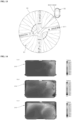
- FIG. 14 is a view showing temperature distribution measured respectively at a top rack 53, an upper rack 52 and a lower rack 51 in the state where dry air is supplied through an airflow guide 83 of the related art
- FIG. 15 is a view showing temperature distribution measured respectively at the top rack 53, the upper rack 52 and the lower rack 51 in the state where dry air is supplied through the airflow guide 83 of one embodiment.
- the temperature deviation in each position of the upper rack 52 and the top rack 53 reveals that temperature decreases from the central portion of the upper rack 52 and the top rack 53 to the outer side of the upper rack 52 and the top rack 53 gradually and slowly, and there is no big temperature deviation between the central portion and the outer side.
- the present disclosure shows that the temperature of the central portion of the top rack 53 also remains quite high, that the temperature of dry air sprayed along the airflow guide 83 of one embodiment remains constant in the tub 20 entirely/dry air sprayed along the airflow guide 83 of one embodiment may make the temperature inside the entire tub 20 constant and that the effect of drying wash targets is promoted noticeably.
- the airflow guide 83 of the dishwasher 1 of one embodiment may comprise a lower guide 831 detachably coupled to the duct main body 851 of the connection duct part 85, an upper guide 832 coupled to the upper side of the lower guide 831, and a cap cover 834 disposed at the upper side of the upper guide 832 and coupled to the outer surface of the upper guide 832.
- the airflow guide 83 may be divided with respect to the up-down direction (U-D direction).
- the lower guide 831 constitutes the lower portion of the segment body.
- the upper guide 832 and the cap cover 834 may constitute the upper portion of the segment body.
- the upper guide 832 is coupled to the upper side of the lower guide 831 described hereafter, and forms a closed inner flow space formed into a channel in which dry airflow F flows together with the lower guide 831.
- the upper guide 832 may be formed into a container which has a vacant space therein, and the lower surface of which is open entirely.
- the open lower surface of the upper guide 832 may be coupled with a guide main body 8311 of the lower guide 831 and be closed entirely. By doing so, a closed inner flow space may be formed between the upper guide 832 and the lower guide 831.
- the outer shape of the upper guide 832 may have a front-rear width greater than a left-right width.
- the upper guide 832 may be formed into a container that has an upper end surface 8321 formed approximately in parallel with a reference surface 8311a of the lower guide 831 described hereafter, and a lower surface being open through an outer wall surface which extends in the downward direction (D-direction) along the circumference of the upper end surface 8321.
- the upper end surface 8321 and the outer wall surface may be integrally formed, and have a uniform thickness as a whole to ensure a maximum inner flow space, and preferably, be manufactured using plastic injection molding.
- the outer wall surface may comprise a first flat surface part 8322c that forms the right side surface of the outer wall surface and is formed into a flat plate, and a second flat surface part 8322d that forms the left side surface of the outer wall surface and is formed into a flat plate.
- the first flat surface part 8322c and the second flat surface part 8322d may have a symmetrical shape, and be formed into a perpendicular surface or an inclined surface having a slope where a gap between the first flat surface part 8322c and the second flat surface part 8322d decreases gradually in the upward direction (U-direction).
- a first curved surface part 8322a may be continuously formed at the front sides of the first flat surface part 8322c and the second flat surface part 8322d
- a second curved surface part 8322b may be continuously formed at the rear sides of the first flat surface part 8322c and the second flat surface part 8322d.
- the first curved surface part 8322a may form the front surface of the upper guide 832, and for example, have an outer shape of a half cylindrical surface that is convex forward.
- the second curved surface part 8322b may form the rear surface of the upper guide 832, and for example, have an outer shape of a half cylindrical surface that is convex rearward.
- the first curved surface part 8322a and the second curved surface part 8322b may be disposed to have an approximately symmetrical shape.
- Each of the first curved surface part 8322a and the second curved surface part 8322b may integrally connect to the upper end surface 8321, the first flat surface part 8322c and the second flat surface part 8322dc, and form a continuous surface for the upper end surface 8321, the first flat surface part 8322c and the second flat surface part 8322d.
- a first camper surface 8322e in a camper shape may be formed at an edge formed between the upper end surface 8321 and the outer wall surface.
- the first camper surface 8322e may help to minimize flow loss or noise caused by eddy currents that may be generated at an angular edge side of the inner flow space in which dry airflow F flows.
- the first camper surface 8322e may be a curved surface having a predetermined curvature, or an inclined surface having a predetermined slope.
- a second camper surface 8322f in a camper shape may be formed at an edge that is formed by the upper end surface 8321 and the first curved surface part 8322a which are met, and at an edge that is formed by the upper end surface 8321 and the second curved surface part 8322b which are met.
- the second camper surface 8322f may be a curved surface having a predetermined curvature, or an inclined surface having a predetermined slope.
- a lower end portion 8323 of the upper guide 832 formed around the open lower surface of the upper guide 832 may be formed continuously while its height remains approximately constant from the upper end surface 8321 with respect to the up-down direction (U-D direction) such that the lower end portion 8323 of the upper guide 832 may be inserted and coupled to a misassembly prevention groove 8311d of the lower guide 831 described hereafter.
- a first notch hole 8324 forming the front edge, the rear edge and the upper end edge of the discharge opening 833 may be formed in the lower end portion 8323 of the upper guide 832.
- the first notch hole 8324 may be formed into a notch where the first flat surface part 8322c and the second curved surface part 8322b of the upper guide 832 are partially cut.
- the lower end of the first notch hole 8324 is entirely open, and as the upper guide 832 is coupled to the lower guide 831, the above-described reference surface 8311a of the lower guide 831 may be coupled to the open lower end of the first notch hole 8324, and the reference surface 8311a may block the lower end of the first notch hole 8324.
- the upper end edge of the first notch hole 8324 may extend approximately in parallel with the reference surface 8311a of the lower guide 831 and may extend linearly.
- the front edge of the first notch hole 8324 may be formed at the first flat surface part 8322c and extend linearly along the up-down direction (U-D direction).
- the rear edge of the first notch hole 8324 may be formed at the second curved surface part 8322b and extend linearly along the up-down direction (U-D direction).
- a rear corner part formed by the upper end edge and the rear edge which are met, and a front corner part formed by the upper end edge and the front edge which are met may respectively have a curved edge having a predetermined curvature.
- a first holding hole 8325 which is formed into a rectangular penetration hole and to which the upper guide holding projection 8312g of the lower guide 831 is held and coupled may be formed at the first curved surface part 8322a of the upper guide 832, near the lower end portion 8323 of the upper guide 832.
- the outer shape of the upper guide 832 is approximately symmetrical with respect to the front-rear direction (F-R direction), but the first notch hole 8324 and the first holding hole 8325 are formed in an asymmetrical position with respect to the front-rear direction (F-R direction).
- the first notch hole 8324 and the first holding hole 8325 may serve as a means of preventing the misassembly of the upper guide 832 to the lower guide 831.
- At least one cap cover holding projection 8326 for fastening the cap cover 834 described hereafter may be integrally formed at the second flat surface part 8322d of the upper guide 832.
- the cap cover 834 may be coupled to the outer surface of the upper guide 832.
- At least one cap cover holding projection 8326 may have a lamp surface having a predetermined angle with respect to the second flat surface part 8322d, and a step surface formed approximately perpendicularly with respect to the second flat surface part, to ensure ease of coupling and prevent ease of separation.
- the cap cover 834 may be provided with a second holding hole 8345 that is formed near the lower end portion 8343 in a way that penetrates the inside and the outside of the cap cover 834.
- the second holding hole 8345 may be formed into a rectangular penetration hole having a width and a height at which the cap cover holding projection 8326 can be inserted into the second holding hole 8345 at a time of coupling the upper guide 832 and the cap cover 834, and like the cap cover holding projection 8326, may be disposed higher than the upper guide holding projection 8312g with respect to the up-down direction.
- the cap cover holding projection 8326 and the second holding hole 8345 may clearly distinguish from the upper guide holding projection 8312g because of the difference in their heights, and the misassembly of the cap cover 834 having a symmetrical shape with respect to the front-rear direction (F-R direction) may be prevented effectively.
- the upper guide 832 of the airflow guide 83 of one embodiment may be provided with a blocking rib 8328 as a first means of minimizing the inflow of wash water into the airflow guide 83 and the connection duct part 85 through the discharge opening 833.
- the blocking rib 8328 may comprise a first rib 8328a that extends in a shade shape along the upper end edge, the front edge and the rear edge of the first notch hole 8324.
- the first rib 8328a extends continuously along the edges of the first notch hole 8324 and protrude approximately perpendicularly with respect to the first flat surface part 8322c of the upper guide 832.
- the first rib 8328a may be formed integrally on the first flat surface part 8322c and the second curved surface part 8322b of the upper guide 832.
- first rib 8328a may be formed at the rear edge of the first notch hole 8324, and the other end portion of the first rib 8328a may be formed at the front edge of the first notch hole 8324.
- the first rib 8328a may extend in a continuous protruding wall shape, between one end portion and the other end portion thereof, to serve as a shade surrounding the first notch hole 8324 approximately entirely.
- one end portion and the other end portion of the first rib 8328a may be respectively spaced a predetermined height from the lower end portion 8323 of the upper guide 832 in the upward direction (U-direction).
- the first rib 8328a may help to minimize the fall of wash targets from the storage part after a wash or the passage of wash water scattered after a fall through the first notch hole 8324.
- a horizontal rib of the first rib 8328a formed at least at the upper end edge of the first notch hole 8324, may horizontally protrude past the first edge wall 8311b of the lower guide 831 and the reference surface 8311a, as illustrated in FIG. 17 .
- the horizontal portion of the first rib 8328a may extend to cover the first edge wall 8311b and the reference surface 8311a with respect to the up-down direction (U-D direction), and in the state where the airflow guide 83 is installed completely, the first edge wall 8311b and the reference surface 8311a are covered and by the first rib 8328a and is not be seen, when view from above.
- the flow of wash water which falls perpendicularly after wash targets are washed, collides with the first edge wall 8311b and then is scattered, into the first notch hole 8324 may be minimized.
- wash water scattered in the washing stage or the rinsing stage may fall in a direction different from the perpendicular direction. That is, wash water avoiding the first rib 8328a, colliding with the first edge wall 8311b and being scattered is likely to flow into the first notch hole 8324.
- the blocking rib 8328 may further comprise at least one second rib 8328b that extends across the inside the first notch hole 8324, along the front-rear direction (F-R direction).
- FIGS. 17 to 18 exemplarily show an embodiment provided with a pair of second ribs 8328b that are spaced in the up-down direction (U-D direction).
- U-D direction up-down direction
- Each of the pair of second ribs 8328b may extend across the inside the first notch hole 8324 and have the same shape.
- the up-down thickness of each of the second ribs 8328b may be much less than the front-rear length.
- the pair of second ribs 8328b may protrude horizontally past the first edge wall 8311b and the reference surface 8311a of the lower guide 831. That is, the horizontal position of the left end portion of the horizontal rib of the first rib 8328a may be the same as the horizontal position of the left end portion of the pair of second ribs 8328b.
- the rear end portion forming one end portion of each of the second ribs 8328b may integrally connect to the rear edge of the first notch hole 8324, and the front end portion forming the other end portion of each of the second rib 8328b may integrally connect to the front edge of the first notch hole 8324.
- the shape of the second rib 8328b may help to prevent the inflow of wash water, in a way that the wash water is blocked by the second rib 8328b again, even if the wash water collides with the first edge wall 8311b by avoiding the first rib 8328a and is scattered.
- a bridge rib 8328c is disposed between the front end portion and the rear end portion of the second rib 8328b and connects the pair of second ribs 8328b mutually to reinforce the second ribs.
- the bridge rib 8328c extends only between the pair of second ribs 8328b, but may further extend to the upper end edge of the first notch hole 8324.
- the upper guide 832 of the airflow guide 83 of one embodiment may be provided with at least one blocking wall 8329 that is disposed in the inner flow space of the upper guide 832, as a second means of minimizing the flow of wash water into the airflow guide 83 and the connection duct part 85 through the discharge opening 833.
- At least one blocking wall 8329 may help to prevent and minimize the movement of the droplets of wash water, which has passed through the blocking rib 8328 and flown into the airflow guide 83 after the wash water's collision and scattering, toward the lower portion of the upper end surface 8321 of the upper guide 832 or toward a duct coupling part 8312 of the lower guide 831.
- At least one blocking wall 8329 may be disposed in the form of a barrier that extends downward from the lower portion of the upper end surface 8321 of the upper guide 832, to at least partially block the upper portion side of the first notch hole 8324 forming the discharge opening 833.
- the up-down position of the lower end of at least one blocking wall 8329 may be between the upper end edge of the first notch hole 8324 and the reference surface 8311a of the lower guide 831. Accordingly, when the inside of the first notch hole 8324 is viewed from the outside, the duct coupling part 8312 of the lower guide 831 is entirely covered by at least one blocking wall 8329 and is not be seen visually from the outside.
- droplets of wash water being scattered and flowing into the airflow guide 83 droplets bouncing upward collide with at least one blocking wall 8329 and flow downward along at least one blocking wall 8329 by using gravity.
- the droplets prevented from coming in and falling downward along at least one blocking wall 8329 need to be discharged out of the airflow guide 83 again.
- the lower end edge of at least one blocking wall 8329 may extend toward a channel guide surface 8313 of the lower guide 831.
- at least one blocking wall 8329 may be disposed in the channel guide surface area with respect to the horizontal direction, as described hereafter. A relative position relationship between the blocking wall 8329 and the channel guide surface 8313 of the lower guide 831 is described hereafter with reference to FIGS. 23 and 24 .
- the blocking wall 8329 may comprise a first blocking wall 8329a disposed relatively close to the first notch hole 8324, and a second blocking wall 8329b disposed farther from the first notch hole 8324 than the first blocking wall 8329a, for example.
- At least one blocking wall 8329 is disposed in the inner flow space where dry airflow F flows.
- the blocking wall 8329 may be divided into the first blocking wall 8329a and the second blocking wall 8329b to complementarily cover the upper portion side of the first notch hole 8324.
- first blocking wall 8329a may be disposed to partially cover the upper portion side of the first notch hole 8324
- the second blocking wall 8329b may be disposed to at least partially cover the remaining portion of the first notch hole 8324 that is not cover by the first blocking wall 8329a.
- the upper end edge of the first blocking wall 8329a may integrally connect to the lower portion of the upper end surface 8321 of the upper guide 832 and be formed into a curved surface that is convex in a direction farther from the first notch hole 8324 forming the discharge opening 833, from one end edge 8329a1 of the first blocking wall 8329a toward the other end edge 8329a2 thereof.
- the upper end edge of the second blocking wall 8329b may integrally connect to the lower portion of the upper end surface 8321 of the upper guide 832 and be formed into a curved surface that is convex in a direction farther from the first notch hole 8324 forming the discharge opening 833, from one end edge 8329b 1 of the second blocking wall 8329b toward the other end edge 8329b2 thereof.
- the flow direction of air having passed through the upper end 8511 of the connection duct part 85 and flown into the inner flow space changes toward the first notch hole 8324 forming the discharge opening 833, as described hereafter. That is, in the process of changing a flow direction, a rotation speed component is produced in dry airflow F.
- the first blocking wall 8329a and the second blocking wall 8329b may also serve as a flow guide.
- the first blocking wall 8329a and the second blocking wall 8329b may be formed into a curved surface having predetermined curvature, and have a uniform thickness from one end edge 8329a1, 8329b1 to the other end edge 8329a2, 8329b2 of each of the first blocking wall 8329a and the second blocking wall 8329b.
- first blocking wall 8329a and the second blocking wall may differ from each other.
- one end edge 8329a1 of the first blocking wall 8329a may be a fixation end portion that integrally connects to the front edge of the first notch hole 8324, and the other end edge 8329a2 of the first blocking wall 8329a may be a free end portion that does not connect to the outer wall surface of the upper guide 832.
- One end edge 8329a1 of the first blocking wall 8329a integrally connects to the front edge of the first notch hole 8324, as described above, such that droplets of wash water are prevented from flowing directly into an upper end 8312a of the duct coupling part 8312 of the lower guide 831 and the upper end 8511 of the connection duct part 85 through the front edge side of the first notch hole 8324, in a minimum distance.
- the up-down position of a lower end edge 8329a3 of the first blocking wall 8329a may change from one end edge 8329a1 of the first blocking wall 8329a to the other end edge 8329a2 thereof.
- the lower end edge 8329a3 of the first blocking wall 8329a may have a step.
- the lower end edge 8329a3 of the first blocking wall 8329a may comprise a first edge 8329a31 the up-down position of which is maintained approximately in a first position, and a second edge 8329a32 the up-down position of which is maintained approximately in a second position. At this time, the first position is lower than the second position, thereby forming a step.
- the first edge 8329a31 may be disposed closer to the one end edge of the first blocking wall 8329a and the front edge side of the first notch hole 8324 than the second edge 8329a32.
- the up-down position of the lower end edge of the first blocking wall 8329a, formed near the front edge side of the first notch hole 8324, may remain lower.
- droplets of wash water may be further prevented from directly flowing into the upper end 8312a of the duct coupling part 8312 of the lower guide 831 and the upper end 8511 of the connection duct part 85, into which dry airflow F comes through the front edge side of the first notch hole 8324, in a minimum distance.
- the first position of the first edge 8329a31 and the second position of the second edge 8329a32 may be lower than the up-down position of the upper end of a division wall provided at the lower guide 831. That is, the lower end edge 8329a3 of the first blocking wall 8329a may entirely extend to a position lower than the up-down position of the upper end of the division wall 8314.
- the second blocking wall 8329b may be disposed in the state of separating from the first blocking wall 8329a and disposed between the first blocking wall 8329a and the second flat surface part 8322d.
- each of one end edge 8329b 1 and the other end edge 8329b2 of the second blocking wall 8329b may be a free end portion that does not connect to the outer wall surface of the upper guide 832.
- the other end edge 8329b2 of the second blocking wall 8329b may be disposed closer to the rear edge of the first notch hole 8324 than the other end edge 8329a2 of the first blocking wall 8329a with respect to the front-rear direction, as described above.
- the up-down position of a lower end edge 8329b3 of the second blocking wall 8329b may remain constant approximately from one end edge 8329b1 to the other end edge 8329b2 and remain higher than the second edge 8329a32 of the first blocking wall 8329a.
- the up-down position of the lower end edge 8329b3 of the second blocking wall 8329b may be entirely lower than the up-down position of the upper end of the division wall 8314 provided at the lower guide 831.
- cap cover 834 disposed at the upper side of the upper guide 832 may be coupled to the outer surface of the upper guide 832 to protect the upper guide 832.
- the upper guide 832 is disposed lower than the storage part that accommodates wash targets, and the upper end surface 8321 and the outer wall surface are disposed in a way that the upper end surface 8321 and the outer wall surface are mostly exposed to the wash space 21 of the tub 20.
- the upper guide 832 is made of a plastic material having relatively low strength.
- the upper guide 832 may be broken directly due to a collision with wash targets that may fall from the storage part between the washing stage and the rinsing stage or may fall while the user withdraws the storage part.
- the cap cover 834 is coupled to the upper side of the outer surface of the upper guide 832 to prevent the damage to the upper guide 832, caused by a collision with wash targets.
- the cap cover 834 may be made of a material having higher breaking strength and corrosion resistance than the upper guide 832, and preferably, may be formed with a sheet of metal such as stainless steel and the like.
- the cap cover 834 may have a shape corresponding to the shape of the outer surface of the upper guide 832.
- the cap cover 834 has a vacant space therein, and is formed into a container that is entirely open.
- the upper guide 832 may be inserted and coupled through an open lower surface of the cap cover 834.
- the outer shape of the cap cover 834 may have a front-rear width greater than a left-right width.
- the cap cover 834 may comprise an upper end surface 8341 formed in parallel with the upper end surface 8321 of the upper guide 832, and an outer wall surface extending along the circumference of the upper end surface 8321 in the downward direction (D-direction).
- the outer wall surface of the cap cover 834 may comprise a first flat surface part 8342c forming a right side surface and being formed into a flat plate, and a second flat surface part 8342d forming a left side surface and being formed into a flat plate.
- the first flat surface part 8342c and the second flat surface part 8342d may have a symmetrical shape, and be formed into a perpendicular surface or an inclined surface having a slope where a gap between the first flat surface part 8342c and the second flat surface part 8342d decreases gradually in the upward direction (U-direction).
- a first curved surface part 8342a may be formed at the front sides of the first flat surface part 8342c and the second flat surface part 8342d
- a second curved surface part 8342b may be continuously formed at the rear sides of the first flat surface part 8342c and the second flat surface part 8342d.
- the first curved surface part 8342a may form the front surface of the cap cover 834, and for example, have an outer shape of a half cylindrical surface that is convex forward in response to the shape of the first curved surface part 8322a of the upper guide 832.
- the second curved surface part 8342b may form the rear surface of the cap cover 834, and for example, have an outer shape of a half cylindrical surface that is convex forward in response to the shape of the second curved surface part 8322b of the upper guide 832.
- Each of the first curved surface part 8342a and the second curved surface part 8342b may be integrally formed on the upper end surface 8341, the first flat surface part 8342c and the second flat surface part 8342d, and form a continuous surface for the upper end surface 8341, the first flat surface part 8342c and the second flat surface part 8342d.
- a camper surface 8342e in a camper shape may be formed at an edge formed between the upper end surface 8341 and the outer wall surface.
- the cap cover 834 is not provided with a component corresponding to the second camper surface 8322f of the upper guide 832.
- the lower end portion 8343 of the outer wall surface of the cap cover 834 may extend to the lower end portion 8323 of the outer wall surface of the upper guide 832 to cover the outer wall surface of the upper guide 832 entirely. Accordingly, at a time of coupling the cap cover 834 to the lower guide 831, the lower end portion 8343 of the cap cover 834 and the lower end portion 8323 of the upper guide 832 may be inserted into the misassembly prevention groove 8311d of the lower guide 831, together.
- a second notch hole 8344 maybe formed in the lower end portion 8343 of the cap cover 834 and have a shape corresponding to that of the first notch hole 8324 of the upper guide 832.
- the second notch hole 8344 may be formed into a notch where the first flat surface part 8342c and the second curved surface part 8342b of the cap cover 834 are partially cut.
- the second notch hole 8344 has the same shape as the first notch hole 8324, a detailed shape of the second notch hole 8344 is not described.
- a holding jaw 8344a may be provided at the lower end of the front edge of the second notch hole 8344 and protrude to the inside of the second notch hole 8344.
- the holding jaw 8344a is a portion that is held and coupled to the other end portion of the above-described first rib 8328a, and the right side portion of the cap cover 834 may be coupled to the upper guide 832 through the holding jaw 8344a.
- the second holding hole 8345 may be formed near the lower end portion 8323 of the upper guide 832, at the second flat surface part 8342d of the cap cover 834, and formed into a rectangular penetration hole to which the above-described cap cover holding projection 8326 of the upper guide 832 is held and coupled.
- the left side portion of the cap cover 834 may be coupled to the upper guide 832.
- the cap cover 834 may be coupled to two spots of the upper guide 832 at least though the holding jaw 8344a and the cap cover holding projection 8326.
- the lower guide 831 may comprise a guide main body 8311 formed into an approximately flat plate.
- the guide main body 8311 may have an outer shape in which a front-rear (F-R direction) width is greater than a left-right (Le-Ri direction) width, in the state where the guide main body 8311 is disposed at the connection duct part 85.
- the left and right edges of the outer edge forming the outer shape of the guide main body 8311 may have a linear shape
- the front edge may have a circular arc shape that is convex forward
- the rear edge may have a circular arc shape that is convex rearward.
- the left and right edges of the guide main body 8311 may have shapes that are approximately symmetrical to each other and parallel with each other, and the front and rear edges of the guide main body 8311 may have shapes that are symmetrical to each other.
- the reference surface 8311a serving as a lower end edge of the above-described discharge opening 833 may be formed at the right edge side of the guide main body 8311.
- the reference surface 8311a as illustrated, may be provided in the form of a flat surface that extends in a direction farther from the discharge opening 833 along the horizontal direction, and extend to the lower end of the channel guide surface 8313 described hereafter from the right edge.
- first edge wall 8311b may be formed at least partially at the left, right, front and rear edges of the guide main body 8311 and extend from the reference surface 8311a in the upward direction (U-direction) by a predetermined height.
- the first edge wall 8311b may be formed continuously along the outer edge of the guide main body 8311. However, the first edge wall 8311b may not be formed at least in the discharge opening area 833 not to prevent the spray of dry air, as illustrated in FIG. 19 .
- a misassembly prevention groove 8311d may be formed inside the first edge wall 8311b and be depressed further downward (in the D-direction) than the reference surface 8311a, with respect to the up-down direction (U-D direction), and serve as a misassembly prevention part of the upper guide 832.
- the height at which the misassembly prevention groove 8311d is depressed from the reference surface 8311a may remain constant approximately along the first edge wall 8311b.
- the lower end portion 8323 of the upper guide 832 which is described hereafter, may be inserted and coupled to the misassembly prevention groove 8311d.
- the misassembly prevention groove 8311d may have a shape and a size corresponding to the shape and the size of the lower end portion 8323 of the upper guide 832.
- the shape of the lower end portion 8323 of the upper guide 832 is formed continuously except for the area where the first notch hole 8324 forming the discharge opening 833 is formed, i.e., the area where the reference surface 8311a is formed.
- the misasssembly prevention groove 8311d may be formed continuously along the first edge wall 8311b.
- the shape of the lower end portion 8323 of the upper guide 832 may be asymmetrical to the shape of the misassembly prevention groove 8311d with respect to the front-rear direction (F-R direction). Accordingly, the lower end portion 8323 of the upper guide 832 may not be coupled and fastened to the misassembly prevention groove 8311d in a direction different from a predetermined direction. By doing so, a misassembly between the upper guide 832 and the lower guide 831 may be prevented effectively.
- a second edge wall 8311c may be formed at the front edge of the guide main body 8311 and extend from the reference surface 8311a in the downward direction (D-direction) to have a predetermined height.
- the second edge wall 8311c may be formed continuously into a cylinder along the circular arc-shaped front edge of the guide main body 8311, and the lower end potion of the second edge wall 8311c may extend past a lower end 8312b of the duct coupling part 8312 that is described below.
- the second edge wall 8311c may be formed in a way that surrounds the outer surface of the below-described duct coupling part 8312 at least partially. At this time, the second edge wall 8311c is formed in the state of being separated and spaced from the duct coupling part 8312, and a predetermined space may be formed between the second edge wall 8311c and the duct coupling part 8312. As described below, an upper end 8522 of a fastening nut 852 may be inserted into the space at least partially.
- a release prevention part 8311e may be provided on the second edge wall 8311c, and based on an interaction with the fastening nut 852, keep the lower guide 831 fixed to the fastening nut 852 and prevent the lower guide 831 from escaping from a fixed position.
- the lower guide 831 is detachably coupled to the duct main body 851 of the connection duct part 85 based on a two-stage coupling manipulation, without an additional coupling member.
- the two-stage coupling manipulation may comprise an up-down perpendicular movement manipulation and a circumferential rotational movement manipulation, for example.
- the release prevention part 8311e prevents a relative rotation of the lower guide 831 in a direction opposite to the direction of the rotational movement in the two-stage coupling manipulation, i.e., prevents the lower guide 831 from escaping from the fixed position after the second-stage coupling manipulation including the perpendicular movement manipulation and the rotational movement manipulation is completed.
- the release prevention part 8311e may be formed integrally on the second edge wall 8311c, and prevent the relative rotation of the lower guide 831 in a direction opposite to the direction of the rotational movement of the two-stage coupling manipulation, in the form of an elastic hook.
- the lower guide 831 as described above, is directly coupled to the duct main body 851 of the connection duct part 85, using a pipe coupling method.
- the lower guide 831 may comprise a cylindrical duct coupling part 8312 to which the upper end 8511 of the cylinder-shaped duct main body 851 is inserted and detachably coupled.
- the duct coupling part 8312 may be formed into a cylinder the central axis C of which extends in parallel with the up-down direction (U-D direction).
- the inner diameter of the lower end 8312b of the duct coupling part 8312 may be greater than or the same as the outer diameter of the upper end 8511 of the duct main body 851.
- the duct coupling part 8312 may be formed integrally at the guide main body 8311, and disposed near the circular arc-shaped rear edge of the guide main body 8311. That is, the duct coupling part 8312 may be biased toward the rear side of the guide main body 8311 with respect to the front-rear direction (F-R direction).
- the upper end 8312a of the cylindrical duct coupling part 8312, from which dry air is discharged, may be formed in a position that protrudes from the guide main body 8311, in the upward direction (U-direction).
- the upper end 8312a of the duct coupling part 8312 protrudes to and is exposed to the inner flow space formed between the guide main body 8311 of the lower guide 831and the upper guide 832.
- the position of the upper end 8312a of the duct coupling part 8312 may be formed in a position lower than the position of the upper end 8511 of the connection duct part 85 with respect to the up-down direction (U-D direction).
- the upper end 8511 of the connection duct part 85 may protrude further upward than the upper end 8312a of the duct coupling part 8312. Since the upper end 8511 of the connection duct part 85 remains higher than the upper end 8312a of the duct coupling part 8312 as described above, the upward movement of droplets of wash water coming in through the discharge opening 833 along a gap between the outer circumferential surface of the connection duct part 85 and the inner circumferential surface of the duct coupling part 8312, caused by a capillary phenomenon, may be fundamentally blocked.
- the central axis of the duct coupling part 8712 may be spaced from the first notch hole 8724 with respect to the front-rear direction (F-R direction) or the horizontal direction. In the embodiment, the central axis of the duct coupling part 8712 may be disposed further forward than the first notch hole 8724. That is, at least the front edge of the first notch hole 8724 is disposed further rearward than the central axis of the duct coupling part 8712.
- a portion of the upper end 8712a of the duct coupling part 8712, exposed outward through the discharge opening 873 or the first notch hole 8724, may be minimized, and the flow of the reversely incoming wash water, having passed through the discharge opening 873, into the duct coupling part 8712 through the upper end 8712a of the duct coupling part 8712 may be minimized.
- a first guide groove 8312d that extends in a linear shape along the up-down direction (U-D direction), and a second guide groove 8312e that extends in a circular arc shape along the circumferential direction may be formed on an inner circumferential surface 8312c of the duct coupling part 8312.
- the upper end of the first guide groove 8312d integrally connects to one end portion of the second guide groove 8312e.
- the lower guide 831 is coupled to the duct main body 851 of the connection duct part 85, based on the two-stage coupling manipulation comprising the up-down perpendicular movement manipulation and the circumferential rotational movement manipulation.
- the first guide groove 8312d extending along the up-down direction (U-D direction) in a linear shape guides the up-down perpendicular movement of the lower guide 831
- the second guide groove 8312e extending along the circumferential direction in a circular arc shape guides the circumferential rotational movement of the lower guide 831.
- a guide projection 8516 may be integrally provided on the outer circumferential surface of the duct main body 851 inserted into and coupled to the duct coupling part 8312 of the lower guide 831, and protrude toward the inner circumferential surface of the connection duct part 85 and be inserted into the first guide groove 8312d and the second guide groove 8312e of the connection duct part 85.
- the guide projection 8516 may be first inserted into the first guide groove 8312d at a time of coupling the lower guide 831 and the duct main body 851.
- the lower guide 831 may move perpendicularly in the downward direction (D-direction).
- the first guide groove 8312d moves in the downward direction (D-direction) along the guide projection 8516 that stands still.
- the lower guide 831 may not move in the downward direction (D-direction) any longer because of the guide projection 8516's action.
- the lower guide 831 may not make a downward (D-direction) movement while making a circumferential rotational movement in the two-stage coupling manipulation.
- the second guide groove 8312e moves along the guide projection 8516 that stands still.
- the lower guide 831 may not rotate in the circumferential direction any longer because of the guide projection 8516's action.
- the lower guide 831 and the duct main body 851 may be coupled completely, the lower guide 831 may be disposed in a fixed position completely, and without an additional coupling member or an additional fastening member, the lower guide 831 and the duct main body 851 may be coupled.
- a stopper projection 8312f may be integrally formed on the inner circumferential surface 8312c of the duct coupling part 8312, at the other end portion side of the second guide groove 8312e, and may form stick-slip in relation to the movement of the guide projection 8516, and after the guide projection 8516 reaches the other end portion of the second guide groove 8312e, stop a relative rotation of the lower guide 831 in the opposite direction.
- the stopper projection 8312f may prevent the guide projection 8516 from escaping from the other end portion of the second guide groove 8312e.
- the airflow guide 83 may not make a self weight-induced movement due to a hold between the second guide groove 8312e and the guide projection 8516.
- the second guide groove 8312e and the guide projection 8516 may be easily released from the hold therebetween.
- the lower guide 831 and the airflow guide 83 are highly likely to clatter because of a gap between the duct coupling part 8312 of the lower guide 831 and the duct main body 851 of the connection duct part 85, caused by manufacturing tolerance.
- the clatter occurs due to a gap-induced relative displacement or relative movement of the lower guide 831 with respect to the connection duct part 85.
- At least one protruding rib may be included as a means of minimizing a gap between the lower guide 831 and the connection duct part 85, in particular, a means of limiting a relative downward movement to the connection duct part 85.
- At least one protruding rib may protrude downward from the lower end 8312b of the duct coupling part 8312. This protruding rib may protrude toward a male screw thread 8541 provided on the outer circumferential surface of the duct main body 851 of the connection duct part 85.
- the airflow guide 83 of the dishwasher of one embodiment may adjust the amount of a generated gap and limit a relative downward movement through the male screw thread 8514 of the duct main body 851.
- the relative movement of the lower guide 831 may be limited in a way that the lower end surface of at least one protruding rib contacts one side surface of the male screw thread 8514.
- FIG. 21 shows at least one protruding rib comprising a first protruding rib 8312h1, a second protruding rib 8312h2 and a third protruding rib 8312h3 that are disposed around a circular opening formed at the duct coupling part 8312 of the lower guide 831.
- at least one protruding rib comprising the first protruding rib 8312h1, the second protruding rib 8312h2 and the third protruding rib 8312h3 is described but not limited.
- the first protruding rib 8312h1, the second protruding rib 8312h2 and the third protruding rib 8312h3, disposed at regular intervals along the circumferential direction, may have the same cross-sectional shape.
- a cross section in a direction perpendicular to the direction in which the protruding rib protrudes may have an approximately rectangular shape.
- the protruding ribs 8312h1, 8312h2, 8312h3 may be formed into a rectangular pillar having the same circumferential width and the same radial width and protrude from the lower end 8312b of the duct coupling part 8312.
- the heights at which the first protruding rib 8312h1, the second protruding rib 8312h2 and the third protruding rib 8312h3 protrude downward from the lower end 8312b of the duct coupling part 8312 may be set differently.
- first protruding rib 8312h1, the second protruding rib 8312h2 and the third protruding rib 8312h3 protrude toward the male screw threads 8514 that extend spirally in different positions.
- a maximum height of the first protruding rib 8312hl, the second protruding rib 8312h2 and the third protruding rib 8312h3 may differ such that a gap between the first, second and third protruding ribs 8312h1, 8312h2, 8312h3 and the male screw thread 8514 remains constant in the position of each of the protruding ribs.
- first protruding rib 8312h1 may protrude at a first height that is the smallest value
- the second protruding rib 8312h2 may protrude at a second height greater than the first height
- the third protruding rib 8312h3 may protrude at a third height greater than the second height.
- the first protruding rib 8312h1, the second protruding rib 8312h2 and the third protruding rib 8312h3, as described hereafter, may be disposed clockwise consecutively, when viewed from the upper portion side of the airflow guide 83.
- the lower end surfaces of the first protruding rib 8312h1, the second protruding rib 8312h2 and the third protruding rib 8312h3 may be provided in the form of an inclined surface, in response to the shape of one side surface of the male screw thread 8514 that extends spirally.
- first protruding rib 8312h1 Detailed configurations of the first protruding rib 8312h1, the second protruding rib 8312h2 and the third protruding rib 8312h3 are described below with reference to FIGS. 28 and 29 .
- At least one upper guide holding projection 8312g may be integrally formed on the outer circumferential surface of the duct coupling part 8312 and couple the upper guide 832 described hereafter and the lower guide 831 mutually.
- At least one upper guide holding projection 8312g may have a lamp surface having a predetermined inclination angle with respect to the outer circumferential surface of the duct coupling part 8312, and a stepped surface formed approximately perpendicularly with respect to the outer circumferential surface of the duct coupling part 8312, such that a coupling based on the downward movement of the upper guide 832 is readily ensured but a separation based on the upward movement of the upper guide 832 is not readily ensured.
- channel guide surface 8313 guiding dry airflow F, having passed through the upper end 8312a of the duct coupling part 8312, to the discharge opening 833 may be formed at the front side of the duct coupling part 8312.
- a curved surface of an inclined surface may be formed continuously between the upper end and the lower end of the channel guide surface 8313 to minimize flow loss of dry airflow F and the amount of generated flow noise.
- the upper end of the channel guide surface 8313 may extend to the approximately same height as the upper end 8312a of the duct coupling part 8312, and the lower end may extend in a curved surface shape or an inclined surface shape to the reference surface 8311a of the lower guide 831.
- the channel guide surface 8313 may be a concave surface that is provided in a way that the channel guide surface 8313 is surrounded by the rear surface of the duct coupling part 8312 and a boundary wall 8313d.
- the channel guide surface 8313 may be formed into a concave surface to prevent droplets of wash water, which collide with the first edge wall 8311b, then are scattered and come in, from moving to the duct coupling part 8312 and the connection duct part 85, after the droplets collide with the channel guide surface 8313 and are scattered again.
- the shape of the channel guide surface 8313 may be formed such that a gap between the channel guide surface 8313 and the upper end surface 8321 of the upper guide 832 remains big to prevent the rescattered droplets of the wash water from bouncing.
- the channel guide surface 8313 may comprise a first inclined surface 8313a extending from the reference surface 8311a in a direction across the duct coupling part 8312, a second inclined surface 8313c having an extension width much less than the first inclined surface 8313a, and a curved surface part 8313b disposed between the first inclined surface 8313a and the second inclined surface 8313c.
- the first inclined surface corresponds to a portion occupying most of the surface area of the channel guide surface 8313. Additionally, the reference surface 8311a and the first inclined surface 8313a are disposed in succession. To suppress the rescattering of wash water to a maximum degree, the first inclined surface 8313a is formed into a flat surface having a minimum climb angle. For example, the climb angle of the first inclined surface 8313a may be about 10 degrees or so with respect to the reference surface.
- the curved surface part 8313b and the second inclined surface 8313c are followed by the first inclined surface 8313a to prevent a rapid change in the inner flow path in which dry airflow F flows.
- the second inclined surface 8313c may be formed into a flat surface, like the first inclined surface 8313a, but has a climb angle much greater than that of the first inclined surface 8313a.
- the climb angle of the second inclined surface 8313c may be about 80 degrees or so with respect to the reference surface 8311a.
- the lower guide 831 of the airflow guide 83 of one embodiment may comprise a division wall 8314 that protrudes upward from the upper end 8312a of the duct coupling part 8312 as a third means of minimizing the flow of wash water into the airflow guide 83 and the connection duct part 85 through the discharge opening 833.
- the division wall 8314 finally blocks droplets of wash water, which have passed through the above-described blocking rib 8328 and blocking wall 8329 in the state of being scattered after a collision, from entering into the duct coupling part 8312.
- the division wall 8314 may protrude upward from the upper end 8312a of the duct coupling part 8312, divide the area where the duct coupling part 8312 is formed and the area where the channel guide surface 8313 is formed, and extend in the form of a barrier that blocks the upper end of the duct coupling part 8312.
- the division wall 8314 may be boundary wall that is disposed between the duct coupling part area and the channel guide surface area and distinguishes the duct coupling part area from the channel guide surface area.
- the thickness of the division wall 8314 may remain constant from the right end portion thereof to the left end portion thereof.
- the right end portion of the division wall 8314 may be a free end portion, and the left end portion may extend to the boundary wall 8313d and integrally connect to the boundary wall 8313d.
- the up-down position of the upper end of the division wall 8314 may remain constant approximately from the right end portion thereof to the left end portion thereof.
- the up-down position of the upper end of the division wall 8314 may be lower than the upper end 8511 of the duct main body 851 and higher than the lower end edge of the blocking wall 8329 of the upper guide 832 such that the division wall 8314 blocks scattered droplets effectively while avoiding interference with the flow of dry airflow F and preventing a rapid increase in the flow resistance of dry airflow F.
- the up-down position of the upper end of the division wall 8314 may be higher than that of the lower end edge 8329b3 of the second blocking wall 8329b that is in the highest position of the lower end edge of the blocking wall 8329 of the upper guide 832.
- the discharge opening 833 of the airflow guide 83 spraying dry air to the wash space 21 of the tub 20 is open in the wash space 21.
- the dry air supply part 80 is in a non-operation state in the washing stage or the rinsing stage, it is highly likely that wash water is scattered in a droplet state and flows into the inner flow space of the airflow guide 83 through the discharge opening 833.
- the droplets of the incoming wash water may also be recondensed in the airflow guide 83, pass through the duct coupling part 8312 and then flow into the dry air supply part 80.
- the airflow guide 83 of one embodiment is provided with a means of preventing the inflow of wash water as follows.
- the first rib 8328a may be provided at the upper end edge, the front edge and the rear edge of the first notch hole 8324 and extend in a shade shape, and at least one second rib 8328b may be provided in the first notch hole 8324 and extend across the first notch hole 8324 along the front-rear direction (F-R direction).
- first blocking wall 8329a and the second blocking wall 8329b may be provided in the first notch hole 8324, and extend downward from the lower portion of the upper end surface 8321 of the upper guide 832 to at least partially cover the upper portion side of the discharge opening 833 or the first notch hole 8324.
- droplets of wash water that flows into the airflow guide 83 in the state of being scattered through the first notch hole 8324 droplets bouncing upward collide with the first blocking wall 8329a and the second blocking wall 8329b and move downward along the first blocking wall 8329a and the second blocking wall 8329b.
- the first blocking wall 8329a and the second blocking wall 8329b are disposed in the channel guide surface area. Accordingly, droplets of wash water, which are blocked by the first blocking wall 8329a and the second blocking wall 8329b, may flow down to the channel guide surface 8313 by using gravity.
- droplets of wash water which are not blocked by the first blocking wall 8329a and the second blocking wall 8329b, may be finally blocked from moving toward the duct coupling part 8312 by the division wall 8314 that protrudes upward from the upper end 8312a of the duct coupling part 8312.
- the up-down position of the upper end of the division wall 8314 is higher than the up-down positions of the lower end edge 8329a3 of the first blocking wall 8329a and the lower end edge 8329b3 of the second blocking wall 8329b.
- droplets of wash water having flown into the airflow guide 83 may be blocked from moving to the duct coupling part 8312 while colliding with the first blocking wall 8329a and the second blocking wall 8329b, but droplets of wash water, which avoid the first blocking wall 8329a and the second blocking wall 8329b and are scattered toward the duct coupling part 8312 while colliding with the channel guide surface 8313, may collide with the division wall 8314 without bouncing higher than the upper end of the division wall 8314.
- droplets of wash water may flow down to the channel guide surface 8313 along the division wall 8314 by using gravity without moving toward the duct coupling part past the upper end of the division wall 8314.
- droplets of wash water, blocked by the first blocking wall 8329a and the second blocking wall 8329b, and droplets of wash water, blocked by the division wall 8314, may move to the channel guide surface 8313 and naturally be discharged to the bottom tub 20c through the discharge opening 833.
- the upper end 8511 of the duct main body 851 protrudes to a position higher than the division wall 8314 of the lower guide 831 while protruding upward from the upper end 8312a of the duct coupling part 8312 of the lower guide 831.
- wash water may be collected on the lower surface 25 of the tub 20 at a predetermined water level or above, in the washing stage or the rinsing stage.
- An increasing water level of wash water may lead to the flow of wash water into the airflow guide 83 through the discharge opening 833 of the airflow guide 83 and the infiltration of water into a gap between the inner circumferential surface 8312c of the duct coupling part 8312 and the outer circumferential surface of the duct main body 851.
- the airflow guide 83 itself is likely to be submerged by wash water.
- wash water having flown into the airflow guide 83 may be discharged out of the airflow guide 83 along the channel guide surface 8313 through the discharge opening 833 again in the state where the water level of the wash water does not exceed the upper end of the division wall 8314.
- the height of the division wall 8314 remains lower than the height of the upper end 8511 of the duct main body 851, as described above.
- the wash water may not reach the upper end 8511 of the duct main body 851, and the wash water having arrived at the upper end 8312a of the duct coupling part 8312 may be discharged from the upper end 8312a of the duct coupling part 8312 to the lower surface 25 of the tub 20 again, through the gap between the inner circumferential surface 8312c of the duct coupling part 8312 and the outer circumferential surface of the duct main body 851.
- wash water may be prevented from flowing into the heater housing 81 and the heater effectively past the upper end 8511 of the duct main body 851 even if the wash water is scattered ad flows into the airflow guide 83 or submerges the airflow guide 83.
- the airflow guide 83 of the dishwasher 1 of one embodiment may help to minimize resistance against the flow of dry airflow f supplied through the upper end 8511 of the duct main body 851 of the connection duct part 85 while blocking and minimizing the movement of droplets of wash water coming in through the first notch hole 8324 and the discharge opening 833 to the duct coupling part 8312 and the duct main body 851, based on the positions of the blocking rib 8328 of the upper guide 832, the blocking wall 8329, the division wall 8314 of the lower guide 831, and the upper end 8511 of the duct main body 851.
- the division wall 8314 since the height of the upper end of the division wall 8314 remains lower than the upper end 8511 of the duct main body 851 into which dry airflow F flows, as illustrated in FIG. 24 , the division wall 8314's resistance against the flow of dry airflow F having passed through the upper end 8511 of the duct main body 851 may be minimized.
- the flow path of dry airflow F having passed through the upper side of the division wall 8314 is partially blocked by the first blocking wall 8329a and the second blocking wall 8329b, but the lower end edge 8329a3 of the first blocking wall 8329a and the lower end edge 8329b3 of the second blocking wall 8329b are spaced upward from the channel guide surface 8313 by a predetermined distance.
- the dry airflow F may flow effectively through a space between the lower end edge 8329a3 of the first blocking wall 8329a and the channel guide surface 8313 and a space between the lower end edge 8329b3 of the second blocking wall 8329b and the channel guide surface 8313.
- the other end edge 8329a2 of the first blocking wall 8329a and the other end edge 8329b2 of the second blocking wall 8329b may be respectively separated from the outer wall surface of the upper guide 832.
- dry airflow F may flow effectively through a space between the other end edge 8329a2 of the first blocking wall 8329a and the outer wall surface of the upper guide 832 and a space between the other end edge 8329b2 of the second blocking wall 8329b and the outer wall surface of the upper guide 832.
- first blocking wall 8329a and the second blocking wall 8329b may help to minimize an increase in the flow resistance against dry airflow F and maximize a flow path of dry airflow F.
- connection duct part 85 the process of assembling and fixing the airflow guide 83 of one embodiment to the connection duct part 85 and a means of limiting movement relative to the connection duct part are described with reference to FIGS. 25 to 27 .
- the lower guide 831 may be coupled to the duct main body 851 of the connection duct part 85 based on a two-stage coupling manipulation.
- the two-stage coupling manipulation may comprise an up-down simple perpendicular movement manipulation and a circumferential simple rotational movement manipulation.
- the airflow guide 83 may be arranged to be disposed at the upper side of the duct main body 851 of the connection duct part 85, as illustrated in FIG. 25 .
- the central axes of the duct main body 851 and the duct coupling part 8312 may be aligned in the up-down direction (U-D direction) to be inserted into the lower end 8312b of the duct coupling part 8312 of the lower guide 831 of the upper end 8511 of the duct main body 851.
- the airflow guide 83 may be rotated clockwise around the duct coupling part 8312 from the fixed position within a predetermined range of angles.
- the position of the airflow guide 83 rotated clockwise is a position in which the guide projection 8516 formed on the outer circumferential surface of the duct main body 851 can be inserted into the first guide groove 8312d of the duct coupling part 8312.
- the airflow guide 83 moves perpendicularly in the downward direction (D-direction) along the direction indicated by the arrow in FIG. 25 such that the upper end 8511 of the duct main body 851 is inserted into the lower end 8312b of the duct coupling part 8312. Accordingly, the guide projection 8516 of the duct main body 851 may be inserted into the lower end portion of the first guide groove 8312d.
- the movement of the first guide groove 8312d of the duct coupling part 8312 is guided by the guide projection 8516 that stands still, and the first guide groove 8312d perpendicularly moves in the downward direction (D-direction).
- the airflow guide 83 may not perpendicularly move in the downward direction (D-direction) any longer, based on the guide projection 8516's action.
- the airflow guide 83 may not make a perpendicular movement in the downward direction (D-direction), but may make a rotational movement circumferentially along the direction indicated by the arrow in FIG. 26(a) .
- the second guide groove 8312e may start to make a rotational movement counterclockwise along the guide projection 8516 that sands still.
- the guide projection 8516 reaches a stopper projection 8312f that is disposed near the other end portion of the second guide groove 8312e.
- stick-slip in relation to the rotation of the airflow guide 83 may be formed by the stopper projection 8312f, and as a rotational force is additionally applied, the guide projection 8516 may go over the stopper projection 8312f.
- the airflow guide 83 may not rotate counterclockwise any longer because of the guide projection 8516's action.
- the airflow guide 83 cannot rotate any longer as described above, the coupling between the lower guide 831 and the duct main body 851 may be completed, and as long as another external force is not applied, the guide projection may be fixed to the other end portion side of the second guide groove 8312e by the stopper projection 8312f, as illustrated in FIG. 27 .
- the airflow guide 83 may be disposed in a fixed position of the connection duct part 85, based on a very simple manipulation or assembly process comprising the simple perpendicular movement manipulation and the simple rotational movement manipulation.
- the lower guide 831 and the airflow guide 83 are highly likely to clatter because of a gap between the duct coupling part 8312 of the lower guide 831 and the duct main body 851 of the connection duct part 85, caused by manufacturing tolerance.
- the release prevention part 8311e may be provided.
- the release prevention part 8311e may be provided with a hook part that is integrally formed on the second edge wall 8311c of the lower guide 831 in a way that a L-shaped notch is formed at the lower end side of the second edge wall 8311c of the lower guide 831, i.e., in a way that the lower end of the second edge wall 8311c is partially cut.
- the hook part constituting the release prevention part 8311e may be disposed near the left edge side of the guide main body 8311 of the lower guide 831, on the second edge wall 8311c.
- the release prevention part 8311e may be formed into a circular arc-shaped plate that is disposed in a way that surrounds the circumference of the fastening nut 852 disposed inside the second edge wall 8311c, in a circular arc shape, and is elastically deformable, as illustrated in FIGS. 28 and 29 .
- fixation end portion 8311e1 integrally connecting to the second edge wall 8311c.
- the fixation end portion 8311e1 may also provide resilient force or elastic force to the other end portion side that is deformed at a time of rotational movement manipulation for installing and fixing the airflow guide 83.
- the other end portion of the release prevention part 8311e separates from the second edge wall 8311c and functions as a free end portion 8311e2. This end portion may directly contact one lateral surface of the stopper 8521 provided in the upper portion of the fastening nut 852 to stop the rotation of the lower guide 831.
- the radial thickness of the free end portion 8311e2 may be greater than the radial thickness of the fixation end portion 8311e1.
- an outer circumferential surface 8311e4 of the release prevention part 8311e and the central axis C of the duct coupling part 8312 remains constant
- an inner circumference surface 8311e3 of the release prevention part 8311e may comprise a portion where a distance from the central axis C of the duct coupling part 8312 remains constant, and a portion where a distance from the central axis C of the duct coupling part 8312 changes.
- the inner circumferential surface 8311e3 of the release prevention part 8311e may comprise a non-contact surface that stays in no contact with the radial outer end portion of the stopper 8521, and a contact surface that is in contact with the radial outer end portion of the stopper 8521, for example.
- the non-contact surface extends toward the free end portion 8311e2 from the fixation end portion 8311e1, has the same curvature as the outer circumferential surface 8311e4 and corresponds to a portion where a distance from the central axis C of the duct coupling part 8312 remains constant.
- the contact surface extends to the free end portion 8311e2 from the position where the non-contact surface ends and corresponds to a portion where a distance from the central axis C of the duct coupling part 8312 decreases gradually.
- the free end portion 8311e2 corresponding to the position where the contact surface ends may protrude further inward than the radial outer end portion of the stopper 8521 in the state where the release prevention part 8311e is not deformed as illustrated in FIG. 28 .
- the contact surface corresponds to a portion that is directly pressurized by the radial outer end portion of the stopper 8521 while the lower guide 832 rotates.
- the contact surface may be formed into a curved surface or an inclined surface such that the relative movement of the radial outer end portion of the stopper 8521 is smoothly made and frictional force decreases, for example.
- a tool groove 8311e5 may be formed on the end portion surface of the free end portion 8311e2 of the release prevention part 8311e and be concave toward the fixation end portion 8311e1 side with respect to the circumferential direction.
- the airflow guide 83 In the state where the airflow guide 83 is fixed in the fixed position completely, even if external force is applied, the airflow guide 83 is configured not to rotate in a direction where the airflow guide 83 separates from the connection duct part 85 as long as the release prevention part 8311e or the stopper 8521 is not broken.
- the airflow guide 83 is formed in a position farthest from the front surface of the tub 20, and the release prevention part 8311e is formed in a position facing the left side surface of the bottom tub 20c.
- the positions are hardly reached by the user, and the user cannot undo the holding state between the release prevention part 8311e and the stopper 8521 easily without an additional tool.
- the tool groove 8311e5 may be provided on the end portion surface of the free end portion 8311e2 of the release prevention part 8311e.
- the tool groove 8311e5 may have a polygonal cross section as illustrated for an ordinary tool to be readily held at a time of undoing the holding state.
- FIGS. 28 and 29 show an embodiment comprising a tool groove 8311e5 having a cross section of a shape, among polygons, for example.
- the release prevention part 8311e is configured to repeat elastically deformation at a time of assembling and separating the airflow guide 83.
- At least one reinforcement rib 8311e6 may be integrally provided on the outer circumferential surface 8311e4 of the release prevention part 8311e and protrude outward in the radial direction.
- the lower guide 831 of the airflow guide 83 may be coupled to the duct main body 851 of the connection duct part 85 based on the two-stage coupling manipulation comprising a simple up-down perpendicular movement manipulation and a simple circumferential rotational movement manipulation.
- the free end portion 8311e2 of the release prevention part 8311e may be disposed in a space between a pair of stoppers 8521 that are adjacent to each other with respect to the circumferential direction, as illustrated in FIG. 28 .
- the space between the pair of adjacent stoppers 8521 may be embodied by a circular arc groove that is open toward the outside in the upward direction and the radial direction.
- the circumferential rotational movement manipulation starts after the up-down perpendicular movement manipulation is completed, out of the pair of stoppers 8521, the radial outer end portion of a stopper 8521 disposed forward with respect to the rotation direction of the airflow guide 83, and the contact surface of the release prevention part 8311e may start to contact each other.
- the release prevention part 8311e is pressurized by the stopper 8521 that stands still, and is pushed gradually outward in the radial direction from an initial position that is no load state and starts to be elastically deformed.
- the release prevention part 8311e may be elastically deformed continuously to the position where the free end portion 8311e2's contact with the radial outer end portion of the stopper 8521 is undone.
- the release prevention part 8311e may instantly return to the initial position with a click by using elasticity.
- the free end portion 8311e2 of the release prevention part 8311e protrudes to the inside of a circular arc groove formed at the front side of the stopper 8521 at the same time as the release prevention part 8311e returns to the initial position.
- the free end portion 8311e2 of the release prevention part 8311e may rotate toward another adjacent stopper 8521 past the previous stopper 8521.
- the free end portion 8311e2 of the release prevention part 83711e may continue to rotate further while going over another stopper 8521, in the same way described above, and the airflow guide 83's rotation in the opposite direction may be limited in the same way.
- the additional rotational movement may be performed until the guide projection provided at the duct main body 851 reaches the other end portion of the second guide groove 8312e, as described above.
- a relative movement, in particular, a downward relative movement, of the airflow guide 83, caused by a gap between the second guide groove 8312e and the guide projection 8516, may be limited and minimized through the protruding ribs 8312h1 to 8312h3.
- the first protruding rib 8312h1, the second protruding rib 8312h2 and the third protruding rib 8312h3 may protrude downward from the lower end 8312b of the duct coupling part 8312.
- FIG. 30 shows that the airflow guide 83 is arranged in a fixed position completely.
- the cap cover 834 and the upper guide 832 are omitted in FIG. 30 .
- a gap having a predetermined width may be formed between the first to third protruding ribs 8312h1, 8312h2, 8312h3 and the male screw thread 8514 of duct main body 851 respectively.
- the first protruding rib 8312hl, the second protruding rib 8312h2 and the third protruding rib 8312h3, disposed at regular intervals around the circular opening formed at the lower end 8312b of the duct coupling part 8312 may have a different maximum protrusion height such that the gap between the protruding ribs and the male screw thread 8514 is maintained at a predetermined level or below in the position of each of the protruding ribs.
- a gap between the first protruding rib 8312h1 and the male screw thread 8514 of the duct main body 851, a gap between the second protruding rib 8312h2 and the male screw thread 8514 of the duct main body 851, and a gap between the third protruding rib 8312h3 and the male screw thread 8514 of the duct main body 851 may differ depending on manufacturing tolerance of each of the protruding ribs.
- the entire amount of a downward relative movement of the airflow guide 83 may be limited based on a gap having a maximum width among the gaps.
- the maximum width of a gap may be 0.01 mm or less, for example.
- the user may not recognize a clatter caused by the amount of relative movement or displacement corresponding to 0.01 mm or less even though each of the protruding ribs 8312h1, 8312h2, 8312h3 does not directly contact the male screw thread 8514 of the duct main body 851.
- the male screw thread 8514 of the duct main body 851 when viewed from above, may be provided as a right-handed screw to be tightened clockwise.
- the male screw thread 8514 extends in a spiral shape the up-down position of which gradually becomes low clockwise, when viewed from above.
- the first protruding rib 8312h1, the second protruding rib 8312h2 and the third protruding rib 8312h3 may be consecutively disposed clockwise.
- the gap between each of the protruding ribs 8312h1, 8312h2, 8312h3 and the male screw thread 8541 of the duct main body 851 may remain similar approximately.
- the protrusion heights of the protruding ribs 8312h1, 8312h2, 8312h3 may gradually become high clockwise in response to the position of the male screw thread 8514 of the duct main body 851 that gradually becomes low clockwise.
- the counterclockwise rotational movement manipulation starts in the state where the perpendicular movement manipulation is completed, the gap between each of the protruding ribs 8312h1, 8312h2, 8312h3 and the male screw thread 8514 of the duct main body 851 may decrease gradually.
- the male screw thread 8514 of the duct main body 851 may have at least three or more windings from an upper end 8514b thereof to a lower end 8514a thereof, for example.
- a screw thread 8523a of the fastening nut 852 may be screw-coupled to the male screw thread 8514 of the duct main body 851.
- the screw thread 8523a of the fastening nut 852 may have two windings that are less than those of the male screw thread 8514 of the duct main body 851, for example.
- the upper side surface of the screw thread of the male screw thread 8514 may remain exposed to the lower end 8312b of the duct coupling part 8312.
- the first protruding rib 8312h1, the second protruding rib 8312h2 and the third protruding rib 8312h3 of the duct coupling part 8312 may be supported by the upper side surface of the male screw thread 8514 of the duct main body 851 at a time of occurrence of a downward relative movement, without being affected by the screw thread 8523a provided on an inner circumferential surface 8523 of the fastening nut 852.
- the radial maximum widths of the first protruding rib 8312h1, the second protruding rib 8312h2 and the third protruding rib 8312h3 may be the same, and be less than a gap between the outer circumferential surface of the connection duct part 85 and the inner circumferential surface 8523 of the fastening nut 852.
- first protruding rib 8312h1, the second protruding rib 8312h2 and the third protruding rib 8312h3 may be in no contact with the inner circumferential surface 8523 and the upper end 8522 of the fastening nut 852.
- a relative position of the third protruding rib 8312h3 with respect to the male screw thread 8514 of the duct main body 851, as illustrated in FIG. 33 may be set regardless of the inner circumferential surface 8523 and the upper end 8522 of the fastening nut 852.
- the lower end surfaces of the first protruding rib 8312h1, the second protruding rib 8312h2 and the third protruding rib 8312h3 may be provided in the form of an inclined surface to correspond to the shape of the upper side surface of the male screw thread 8514 of the duct main body 851, which extends spirally.
- the inclination angles of the lower end surfaces of the first protruding rib 8312h1, the second protruding rib 8312h2 and the third protruding rib 8312h3 may be approximately the same as that of the male screw thread 8514 of the duct main body 851.
- the second protruding rib 8312h2 and the third protruding rib 8312h3 contacts the male screw thread 8514 of the duct main body 851 because of the airflow guide 83's downward relative movement caused by external force
- at least any one of the first protruding rib 8312h1, the second protruding rib 8312h2 and the third protruding rib 8312h3 may be in contact with the male screw thread 8514 of the duct main body 851.
- the lower end surface of at least any one of the first protruding rib 8312h1, the second protruding rib 8312h2 and the third protruding rib 8312h3 may be entirely supported by the male screw thread 8514 of the duct main body 851.
- the upper side surface of the male screw thread 8514 supports the protruding ribs 8312h1 to 8312h3.
- the downward relative movement of the airflow guide 83 may be effectively limited, and the airflow guide 83 may be reliably supported, despite strong external force.
- the fastening nut as described above, is screw-coupled to the outer circumferential surface of the connection duct part 85.
- the fastening nut may fixe the connection duct part 85 to the lower surface 25 of the bottom tub 20c.
- the fastening nut 852 may have a cylindrical shape entirely.
- This fastening nut 852 may be provided with a screw thread 8523a on the cylinder-shaped inner circumferential surface 8523a thereof.
- the screw thread 8523a may have a female screw shape and is screw-coupled to the male screw thread 8514 of the duct main body 851 of the connection duct part 85.
- the screw thread 8523a of the fastening nut may have two windings, for example.
- the fastening nut 852 is screw-coupled to the male screw thread 8514 of the duct main body 851.
- the upper end 8511 of the duct main body 851 may be fixed to the tub 20, in the state of being exposed to the inside of the tub 20.
- the fastening nut 852 is in close contact with the upper portion side of the lower surface 25 of the bottom tub 20c, and a flange 8513 of the duct main body 851 is in close contact with the lower portion side of the lower surface 25 of the bottom tub 20c, the flange 8513 receives the force of being pulled toward the lower surface of the bottom tub 20c, because of the fastening nut 852's coupling force.
- an airtight ring made of an elastic material may be further provided between the flange 8513 and the lower surface 25 of the bottom tub 20c.
- a plurality of stoppers 8521 may be provided at the upper end side of the fastening nut 852 and interact with the release prevention part 8311e of the airflow guide 83.
- the plurality of stoppers 8521 may be formed in a way that the upper end 8522 and the outer circumferential surface 8524 of the fastening nut 852 are depressed partially, and each of the plurality of stoppers 8521 may be disposed along the circumferential direction at regular intervals.
- the other end portion of the release prevention part 8311e of the airflow guide 83 separates from the second edge wall 8311c and functions as a free end portion 8311e2, and directly contacts one side surface of the stopper 8521 of the fastening nut 852 and limits the rotational movement of the airflow guide 83 to prevent the airflow guide 83's escape from the right position thereof.
- the fastening nut 852 is directly exposed to wash water in the washing stage and the rinsing stage.
- the fastening nut 852 is directly exposed to the wash pace.
- the fastening nut 852 may be submerged in wash water filling the lower surface 25 of the bottom tub 20c, since it is disposed at the upper side of the lower surface 25 of the bottom tub 20c.
- the fastening nut 852 may be manufactured, based on a plastic injection molding process.
- a lower end surface 8525 of the fastening nut 852 is in close contact with the lower surface 25 of the bottom tub 20c directly.
- a minute gap may be formed between the lower surface 25 of the bottom tub 20c and the lower end surface 8525 of the fastening nut 852, in close contact, due to their manufacturing tolerance.
- wash water may flow into a space formed by the inner circumferential surface 8523 of the fastening nut 852, the outer circumferential surface of the duct main body 851 and the lower surface 25 of the bottom tub 20c.
- the wash water can hardly be discharged out of the fastening nut 852 once the wash water flows into the space.
- the lower surface 25 of the bottom tub 20c is highly likely to be corroded by the wash water which is drawn but not discharged.
- the dry air supply hole 254 is formed inside the fastening nut 852 in a way that the bottom tub 20c is perforated, the dry air supply hole 254 is highly likely to corrode, and germs included in wash water are reproduced generating a bad smell.
- the fastening nut 852 provided at the dishwasher 1 of one embodiment may comprise a plurality of contact projections 8526 that extends toward the bottom tub 20c from the lower end surface 8525.
- Each of the plurality of contact projections 8526 may have an upper end that integrally connects to the fastening nut 852, and a lower end that extends toward the bottom tub 20c in the form of a protruding rib. Specifically, the upper end of the contact projections 8526 may connect to the lower end surface 8525 of the fastening nut 852. Further, the lower end of the contact projections 8526 may extend toward the lower surface 25 of the bottom tub 20c.
- Each of the plurality of contact projections 8526 may be spaced from one another by a predetermined circumferential distance Dc, on the lower end surface 8525 of the fastening nut 852, in the circumferential direction.
- the predetermined circumferential distance may be greater than a maximum circumferential thickness Wc of each contact projection 8526.
- a wash water passage through which wash water comes in and out may be provided between the contact projections 8526, and the lower end surface 8525 of the fastening nut 852 may be separated from the lower surface 25 of the bottom tub 20c and exposed to the wash space.
- wash water may be effectively discharged out of the fastening nut without staying in the space formed by the inner circumferential surface 8523 of the fastening nut 852, the outer circumferential surface of the duct main body 851 and the lower surface 25 of the bottom tub 20c.
- the corrosion of the bottom tub 20c i.e., the corrosion of the dry air supply hole 254, may be prevented effectively.
- each contact projection 8526 may have the same outer shape.
- each contact projection 8526 may be formed into a sharp edge having a horizontal cross section of which decreases gradually from an upper end to a lower end, for example.
- a contact end portion 8526a at the lower end of the contact projection 8526, contacting the lower surface 25 of the bottom tub 20c, may be formed into a curved surface that is convex toward the lower surface 25 of the bottom tub 20c. Accordingly, the contact projection 8526 and the bottom tub 20c may remain at least in a linear contact state.
- the shape of the contact projection may help to distribute the fastening nut 852's coupling force or pressurizing force uniformly through the each of the contact projections 8526 and apply the same to the lower surface 25 of the bottom tub 20c. Further, the sharp edge shape of the contact projection may help to minimize foreign substances such as food and the like fitted or fixed between the contact projection 8526 and the bottom tub 20c.
- the dry air supply hole 254 through which the upper end 8511 of the duct main body 851 passes, is formed on a convergence surface 251 for guiding wash water to the sump hole 252.
- the convergence surface 251 has a predetermined convergence inclination angle with respect to the horizontal direction to allow wash water to be moved by gravity.
- the pressurizing force of the fastening nut 852 that moves perpendicularly at a time of screw-coupling the fastening nut 852 to the male screw thread 8514 of the duct main body 851 may not be applied uniformly through the contact projection 8526.
- a ring-type coupling surface 2541 may be formed around the dry air supply hole 254 and be pressurized by the contact end portion 8526a of the lower end of the contact projection 8526.
- the ring-type coupling surface 2541 may have directionality that extends in the horizontal direction perpendicular to the perpendicular direction where the fastening nut 852 is moved while being screw-coupled.
- the ring-type coupling surface 2541 may be a ring-type bead surface that is formed in a way that the surrounding area of the dry air supply hole 254 is pressed and plastic-deformed.
- each contact projection 8526 may apply its pressurizing force to the bottom tub 20c uniformly or evenly.
- bottom tub 20c may be further provided with a cylindrical part 2542 that extends circumferentially along the dry air supply hole 254 and protrudes upward toward the lower end surface 8525 of the fastening nut 852.
- the cylindrical part 2542 intends to extend upward the height of a flooding water surface of wash water filling the lower surface 25 of the bottom tub 20c.
- the height at which the cylindrical part 2542 protrudes from the lower surface 25 of the bottom tub 20c may be less than the height at which the contact projection 8526 protrudes from the lower end surface 8525 of the fastening nut 852.
- the height at which the cylindrical part 2542 protrudes from the lower surface 25 of the bottom tub 20c may remain constant along the circumferential direction.
- wash water flows into the dry air supply hole 254 directly and that the dry air supply hole 254 and the cylindrical part 2542 are corroded by wash water.
Landscapes
- Washing And Drying Of Tableware (AREA)
Abstract
Description
- Disclosed herein is a dishwasher, and in particular, a dishwasher that can prevent an airflow guide from clattering effectively without an additional member and support the airflow guide reliably, allow a lower end surface of a fastening nut to be exposed to a wash space, prevent wash water from remaining between the fastening nut and a tub, and prevent the tub and a dry air supply hole from corroding.
- Dishwashers spray wash water such as water to a wash target such as cooking vessels, cooking tools and the like accommodated in them to wash the wash target. At this time, wash water used for washing a wash target can include detergent.
- In some cases, dishwashers are comprised of a tub forming a wash space, a storage part accommodating wash targets in the tub, a spray arm spraying wash water to the storage part, and a sump storing water and supplying wash water to the spray arm.
- Dishwashers help to reduce time and efforts taken to clean wash targets such as cooking vessels and the like after meals, thereby ensuring improvement in user convenience.
- In some cases, dishwashers perform a washing process of washing wash targets, a rinsing process of rinsing the wash targets, and a drying process of drying the wash targets after the washing and rinsing processes.
- In recent years, the drying stage of dishwashers involves supplying high-temperature dry air into the tub to reduce a drying period and promote the effect of sterilizing wash targets.
- As a related art, a dishwasher provided with a hot air supply device that generates and supplies high-temperature dry air after the washing and rinsing stages is disclosed in
DE Patent Publication No. 102015212869 (document 001). - In the dishwasher according to document 001, a dry air spray part for spraying dry air generated through the hot air supply device, which is disposed under of a tub, into the tub is disposed in the tub.
- The dry air spray part is coupled to a hot air supply tube that extends in a way that penetrates the tub.
- At this time, the dry air spray part can be coupled to the hot air supply tube simply by being press-fitted to the hot air supply tube, thereby ensuring a simple assembly or fastening.
- However, according to document 001, without a very tight manufacturing tolerance for the dry air spray part and the hot air supply tube, clattering can occur due to a relative displacement or a relative movement that is caused by an up-down gap.
- Additionally, according to document 001, without rigidity of a predetermined level or above in a connecting portion between the dry air spray part and the hot air supply tube, the dry air spray part can easily escape upward and downward from its right position as quite a strong impact is applied.
- Further, according to document 001, without rigidity of a predetermined level or above in the connecting portion between the dry air spray part and the hot air supply tube, the connecting portion between the dry air spray part and the hot air supply tube can be readily broken as quite a strong impact is applied.
- Further, the dry air spray part according to document 001 extends vertically through an open hole that is formed in a way that penetrates the lower surface of the tub.
- Accordingly, a connecting portion between the open hole and the dry air spray part is exposed to high-temperature wash water, and when wash water remains in the connecting portion after the washing stage and the rinsing stage, the open hole and the lower surface side of the tub are highly likely to corrode.
- Further, it is highly likely that wash water and food included in the wash water remaining in the connection portion between the open hole and the dry air spray part can cause the reproduction of germs and generate a bad smell.
- Further, since the dry air spray part according to document 001 is not fixed to the hot air supply tube in a rotation direction, the dry air spray part is likely to collide with the edge of the tub depending on the operation state of the dishwasher.
- Accordingly, the dry air spray part can be broken or generate noise due to its collision with the edge of the tub.
- Further, the dry air spray part according to document 001 has an outer shape corresponding to the shape of the edge of the tub. Accordingly, the outer shape of the dry air spray part can be big.
- As the dry air spray part having a big outer shape is disposed in the wash space, an available wash space of the tub can be reduced substantially, and interference with other components including a lower spray arm and a lower rack, disposed in the tub, can occur. Further, since the dry air spray part needs to be disposed closet to the tub, food and the like is highly likely to be fixed between the dry air spray part and the inner surface of the tub.
- The first objective of the present disclosure is to provide a dishwasher in which a means of limiting a relative displacement or a relative movement is provided integrally between an airflow guide and a connection duct part to which the airflow guide connects, such that the airflow guide is reliably supported and effectively prevented from clattering without an additional member.
- The second objective of the present disclosure is to provide a dishwasher in which a screw part integrally provided at a connection duct part is supported at at least three different spots at a time of a relative downward displacement or a relative downward movement of the airflow guide, such that even if quite a strong external force is applied, the airflow guide is effectively prevented from escaping from its right position.
- The third objective of the present disclosure is to provide a dishwasher in which a screw part integrally provided at a connection duct part is supported at at least three different spots at a time of a relative downward displacement or a relative downward movement of the airflow guide, such that the airflow guide and the connection duct part are effectively prevented from being broken since external force is divided and transferred to the connection duct part through the three different spots.
- The fourth objective of the present disclosure is to provide a dishwasher in which a connection duct part, extending in a way that penetrates a dry air supply hole, is fixed in the state of being spaced from the lower surface of a fastening nut fixed to a tub, such that the lower end surface of the fastening nut is exposed to a wash space, wash water is prevented from remaining between the fastening nut and the tub, and the tub and the dry air supply hole are prevented from corroding.
- The fifth objective of the present disclosure is to provide a dishwasher in which wash water is prevented from remaining between a fastening nut and a tub, to effectively prevent the reproduction of germs and the generation of a bad smell between the fastening nut and the tub.
- The sixth objective of the present disclosure is to provide a dishwasher in which a release prevention part is integrally provided to prevent an airflow guide from rotating and escaping in the state of being coupled and fixed, thereby providing dry air reliably in a predetermine direction regardless of the operation state of the airflow guide.
- The seventh objective of the present disclosure is to provide a dishwasher in which an airflow guide is sufficiently spaced from the edge of a tub, such that the damage and noise of the airflow guide, caused by its collision with the edge of the tub, are minimized.
- The eighth objective of the present disclosure is to provide a dishwasher in which an airflow guide is coupled to a dry air supply part, based on a two-stage coupling manipulation, to readily implement the setting of the right position of the airflow guide with respect to the dry air supply part and effectively prevent the misassembly of the airflow guide with respect to the dry air supply part.
- Aspects according to the present disclosure are not limited to the above ones, and other aspects and advantages that are not mentioned above can be clearly understood from the following description and can be more clearly understood from the embodiments set forth herein. Additionally, the aspects and advantages in the present disclosure can be realized via means and combinations thereof that are described in the appended claims.
- A dishwasher according to the present disclosure comprises a tub accommodating a wash target and having a wash space a front surface of which is open; a dry air supply part being disposed at a lower portion side of the tub and generating dry air for drying the wash target; an airflow guide diverting a flow direction of the dry air supplied by the dry air supply part and supplying the dry air to the wash space, wherein the dry air supply part comprises a connection duct part having an upper end that extends by penetrating a lower surface of the tub upward and supplying the dry air into the airflow guide; and a relative movement limiter limiting a rotational movement and a downward movement of the airflow guide relative to the connection duct part in a state in which the airflow guide is coupled to the connection duct part completely.
- Alternatively, a dishwasher according to the present disclosure comprises a tub that defines a wash space configured to accommodate a wash target, the tub having a front surface that is open; a dry air supply part configured to generate dry air for drying the wash target; and an airflow guide configured to guide the dry air generated by the dry air supply part to the wash space. The dry air supply part comprises: a connection duct part that extends upward and passes through a lower surface of the tub, the connection duct part being coupled to the airflow guide and configured to supply the dry air into the airflow guide, and a movement limiter configured to, based on the airflow guide being coupled to the connection duct part, limit a rotational movement and a downward movement of the airflow guide relative to the connection duct part.
- The airflow guide may comprise a cylindrical duct coupling part into which the upper end of the connection duct part is inserted and coupled. The relative downward movement of the duct coupling part may be limited by a male screw thread.
- The relative movement limiter may comprise at least one of protruding ribs that are formed in a way that protrudes downward toward the male screw thread at the lower portion of the duct coupling part. At a time of the relative downward movement, the lower end surface of at least one of the protruding ribs may contact the male screw thread.
- As the duct coupling part and the connection duct part are coupled completely, a gap having a predetermined width may be formed between the lower end surface of at least one of the protruding ribs and the male screw thread. The relative downward movement may be limited to the predetermined width or less.
- At least one of the protruding ribs may comprise a first protruding rib, a second protruding rib and a third protruding rib that are arranged at regular intervals around a circular opening through which the upper end of the connection duct part passes.
- The heights at which the first protruding rib, the second protruding rib and the third protruding rib protrude downward from the lower portion of the duct coupling part may differ respectively.
- Additionally, a maximum height of the first protruding rib protruding from the lower portion of the duct coupling part may be a first height, a maximum height of the second protruding rib protruding from the lower portion of the duct coupling part may be a second height greater than the first height, and a maximum height of the third protruding rib protruding from the lower portion of the duct coupling part may be a third height greater than the second height.
- Further, a circumferential width of the first protruding rib, a circumferential width of the second protruding rib and a circumferential width of the third protruding rib may be the same.
- Further, when viewed from the upper portion side of the airflow guide, the first protruding rib, the second protruding rib and the third protruding rib may be consecutively disposed clockwise at the lower end of the connection duct part.
- Further, a lower end surface of the first protruding rib, a lower end surface of the second protruding rib and a lower end surface of the third protruding rib, protruding from the lower portion of the duct coupling part, may be inclined surfaces the height of which respectively increases clockwise.
- The dry air supply part may further comprise a fastening nut disposed at the connection duct part. The fastening nut may be screw-coupled to the male screw thread of the connection duct part to fix the connection duct part to the lower surface of the tub. As the duct coupling part and the connection duct part are coupled completely, at least one of the protruding ribs may be in no contact with the fastening nut.
- Further, a radial maximum width of at least one of the protruding ribs may be less than a gap between the outer circumferential surface of the connection duct part and the inner circumferential surface of the fastening nut.
- At least one of the protruding ribs may be inserted into the fastening nut.
- The duct coupling part may be coupled to the connection duct part, based on a two-stage coupling manipulation.
- Further, the two-stage coupling manipulation may comprise a perpendicular movement manipulation of relatively moving the airflow guide downward; and a rotational movement manipulation of relatively moving the airflow guide circumferentially after the perpendicular movement manipulation is completed.
- As the rotational movement manipulation starts, the gap between the lower end surface of at least one of the protruding ribs and the male screw thread may decrease gradually.
- Further, as the rotational movement manipulation starts, the airflow guide may rotate in a direction opposite to the direction in which the airflow guide rotates to screw-couple the fastening nut to the male screw thread of the connection duct part.
- Further, the relative movement limiter may further comprise a first guide groove that is formed on the inner circumferential surface of the duct coupling part and extends linearly along an up-down direction. The relative movement limiter may further comprise a second guide groove that has one end portion integrally connecting to an upper end of the first guide groove and extends along a circumferential direction in a circular arc shape. The relative movement limiter may further comprise a guide projection may be provided on the outer circumferential surface of the connection duct part, protrudes toward the inner circumferential surface of the connection duct part, and moves along the first guide groove and the second guide groove at a time of the two-stage coupling manipulation.
- Further, in the state in which the guide projection is inserted into the first guide groove, the perpendicular movement manipulation may be guided, and in the state in which the guide projection is inserted into the second guide groove, the rotational movement manipulation may be guided.
- Further, as the rotational movement manipulation is completed, a relative upward movement of the guide projection of the duct coupling part may be limited by the second guide groove.
- Further, in the state in which the fastening nut is screw-coupled to the connection duct part completely, the lower end surface of the fastening nut may be exposed to the wash space at least partially.
- The fastening nut may comprise a plurality of contact projections extending from the lower end surface of the fastening nut. Each contact projection may have an upper end that respectively connects to the lower end surface of the fastening nut integrally, and having a lower end that extends toward the lower surface of the tub.
- Each of the plurality of contact projections may be space from each other on the lower end surface of the fastening nut along the circumferential direction at predetermined circumferential intervals.
- The predetermined circumferential interval of the plurality of contact projections may be maintained regularly.
- The predetermined circumferential interval may be greater than a maximum circumferential thickness of the plurality of contact projections.
- Each of the plurality of contact projections may have the same outer shape.
- Each of the plurality of contact projections may have an outer shape the horizontal cross section of which decreases gradually from the upper end to the lower end.
- The lower end of each of the contact projections, contacting the lower surface of the tub, may be formed into a curved surface that is convex toward the lower surface of the tub.
- Further, a dry air supply hole may be provided on the lower surface of the tub, and the upper end of the connection duct part may pass and extend through the dry air supply hole, and a ring-type coupling surface may be formed around the dry air supply hole and pressurized by the lower end of the contact projection.
- The coupling surface may extend in a direction perpendicular to the direction in which the fastening nut moves while being screw-coupled to the connection duct part.
- The direction in which the fastening nut moves while being screw-coupled to the connection duct part may be a perpendicular direction, and the direction in which the coupling surface extends may be a horizontal direction.
- Further, a convergence surface having a predetermined downward inclination angle with respect to the horizontal direction may be provided around the coupling surface.
- Further, a cylindrical part may be provided on the lower surface of the tub, and extend circumferentially along the dry air supply hole and protrude upward toward the lower end surface of the fastening nut.
- The height of the cylindrical part protruding from the lower surface of the tub may remain constant along the circumferential direction.
- The height of the cylindrical part protruding from the lower surface of the tub may be less than the height of the contact projection protruding from the lower end surface of the fastening nut.
- The airflow guide may be detachably coupled to the dry air supply part without an additional coupling member.
- The dry air supply part may comprise a connection duct part that extends in a way that penetrates the lower surface of the tub upward, and supplies the dry air to the airflow guide, and the airflow guide may be detachably coupled to the connection duct part.
- The airflow guide may be coupled to the connection duct part, based on a two-stage coupling manipulation.
- The two-stage coupling manipulation may comprise a perpendicular movement manipulation of relatively moving the airflow guide downward.
- The two-stage coupling manipulation may comprise a rotational movement manipulation of relatively moving the airflow guide circumferentially after the perpendicular movement manipulation is completed.
- The airflow guide may comprise a duct coupling part having an upper end that is exposed to an inner flow space, and a lower end that connects to the connection duct part, and having a cylindrical shape. The upper end of the cylindrical connection duct part may be coupled to the lower portion of the duct coupling part, based on the two-stage coupling manipulation.
- The upper end of the connection duct part may be inserted into the lower end of the duct coupling part.
- Further, a first guide groove and a second guide groove may be formed on the inner circumferential surface of the duct coupling part, and the first guide groove may extend linearly along the up-down direction, and the second guide groove may have one end portion integrally connecting to the upper end of the first guide groove and extending along the circumferential direction in a circular arc shape.
- Further, a guide projection may be provided on the outer circumferential surface of the connection duct part, and may protrude toward the inner circumferential surface of the connection duct part and join the first guide groove and the second guide groove.
- In the state where the guide projection joins the first guide groove, the perpendicular movement manipulation may be guided.
- Further, in the state where the guide projection joins the second guide groove, the rotational movement manipulation may be guided.
- Further, a stopper projection may be integrally provided at the second guide groove, and the stopper projection may be disposed near the other end portion of the second guide groove, and after the rotational movement manipulation is completed, block the generation of a relative rotation in a direction opposite to the direction of the rotational movement manipulation.
- The relative movement limiter may further comprise a release prevention part configured to restrict the airflow guide from rotating. In other words, the release prevention part may keep the airflow guide fixed after the rotational movement manipulation is completed. The release prevention part thus may prevent the airflow guide from rotating in a direction opposite to the direction of the rotational movement manipulation.
- One end portion of the release prevention part may be a fixed end portion that integrally connects to the airflow guide, and the other end portion of the release prevention part may be a free end portion that separates from the airflow guide and is elastically deformed.
- The dry air supply part may further comprise a fastening nut that is screw-coupled to the connection duct part and fixes the connection duct part to the tub, and at least one stopper may be integrally provided at the upper end of the fastening nut and join the free end portion of the release prevention part to prevent the airflow guide from rotating in a direction opposite to the direction of the rotational movement manipulation.
- The airflow guide may further comprise a release prevention part that keeps the airflow guide fixed after the rotational movement manipulation is completed.
- The release prevention part may prevent the airflow guide from rotating in a direction opposite to the direction of the rotational movement manipulation.
- The dry air supply part may comprise a connection duct part that extends in a way that penetrates the lower surface of the tub in the upward direction and supplies the dry air to the airflow guide, and the airflow guide may be detachably coupled to the connection duct part and prevented from rotating relative to the connection duct part in the opposite direction by the release prevention part.
- The airflow guide may comprise a lower guide which is coupled to the connection duct part and into which dry air generated in the dry air supply part is drawn; and an upper guide which is coupled to the upper side of the lower guide and has a flow space in which the dry air flows, the lower guide, comprising: a duct coupling part having an upper end that is exposed to the flow space and a lower end that is coupled to the connection duct part and having a cylindrical shape; and an edge wall that is formed in a way that surrounds the outer surface of the duct coupling part at least partially, and spaced from the duct coupling part, and the release prevention part may be integrally formed on the edge wall.
- The release prevention part may be formed in a way that the lower end of the edge wall is partially cut.
- Further, one end portion of the release prevention part may be a fixed end portion that integrally connects to the airflow guide, and the other end portion of the release prevention part may be a free end portion that separates from the airflow guide and is elastically deformed.
- Further, a radial thickness of the free end portion may be greater than a radial thickness of the fixed end portion.
- The dry air supply part may further comprise a fastening nut that is screw-coupled to the connection duct part and fixes the connection duct part to the tub, and at least one of stoppers may be integrally provided at the upper end of the fastening nut, and join the free end portion of the release prevention part and prevent the airflow guide from rotating in a direction opposite to the direction of the rotational movement manipulation.
- At least one of the stoppers may comprise a first stopper and a second stopper that are arranged one after another along the circumferential direction, and in the state in which the release prevention part is not elastically deformed, the free end portion may protrude at least partially further inward than the radial outer side end portion of the first stopper and the radial outer side end portion of the second stopper with respect to a radial direction.
- If the airflow guide relatively rotates in a direction opposite to the direction of the rotational movement manipulation, the free end portion may contact any one of one side surface of the first stopper or one side surface of the second stopper.
- The inner circumferential surface of the release prevention part, facing the connecting duct part, may extend toward the free end portion from the fixed end portion in the circumferential direction, and comprise a non-contact surface that is in no contact with the radial outer side end portion of the first stopper or the radial outer side end portion of the second stopper; and a contact surface that is formed after the non-contact surface in succession, and at a time of the rotational movement manipulation, contacts the radial outer side end portion of the first stopper or the radial outer side end portion of the second stopper.
- The free end portion of the release prevention part may be elastically deformed based on contact with the radial outer side end portion of the first stopper or the radial outer side end portion of the second stopper.
- Further, a distance between the contact surface and the central axis of the duct coupling part may decrease gradually toward the free end portion.
- The free end portion of the release prevention part may be provided with an end portion surface that is formed in a parallel direction with the radial direction, and a tool groove may be provided on the end portion surface and concave toward the fixed end portion.
- Furthermore, at least one of reinforcement ribs may be integrally provided on the outer circumferential surface of the release prevention part, and protrude outward in the radial direction and extend along the circumferential direction.
- A dishwasher according to the present disclosure may have the effects of evenly distributing dry air and ensuring a sufficient period for which dry air stays in a tub, thereby improving drying efficiency and reducing a drying period.
- The dishwasher according to the present disclosure has the effect of preventing wash water from being reversely drawn through a discharge opening that is directly exposed to a wash space.
- The dishwasher according to the present disclosure has the effect of preventing an airflow guide from escaping from a set position or clattering through a simple structure after the airflow guide is assembled and fixed to a dry air supply part.
- The dishwasher according to the present disclosure has the effect of preventing the airflow guide from escaping from its right position or being broken due to an external impact after the airflow guide is assembled and fixed to the dry air supply part.
- The dishwasher according to the present disclosure has the effect of preventing the corrosion of the tub and a dry air supply hole and preventing the reproduction of germs and the generation of a bad smell between the tub and a fastening nut since the lower end surface of the fastening nut is exposed to a wash space to prevent wash water from remaining between the fastening nut and the tub.
- The dishwasher according to the present disclosure has the effect of simplifying the processes of assembling and fixing the airflow guide to the dry air supply part since the assembly structure and fixation structure of the airflow guide spraying dry air are simplified.
- The dishwasher according to the present disclosure has the effect of preventing a change in a predetermined position of a discharge opening through a means of preventing the misassemble between an upper guide and a lower guide that constitute the airflow guide.
- The dishwasher according to the present disclosure has the effect of preventing the airflow guide from releasing or escaping from its set position through a simple structure after the airflow guide is assembled and fixed to the dry air supply part.
- Alternatively, a dishwasher according to the present disclosure comprises: a tub that defines a wash space configured to accommodate a wash target, the tub having a front surface that is open; a dry air supply part configured to generate dry air for drying the wash target; and an airflow guide configured to guide the dry air generated by the dry air supply part to the wash space, the dry air supply part comprises a connection duct part that passes through a surface of the tub, the connection duct part being coupled to the airflow guide and configured to supply the dry air into the airflow guide, and wherein the dry air supply further comprises a fastening nut that is screw-coupled to the connection duct, and wherein the fastening nut comprises a plurality of contact projections that extend from the lower end surface of the fastening nut toward the surface of the tub.
- Specific effects are described along with the above-described effects in the section of detailed description.
- The accompanying drawings constitute a part of the specification, illustrate one or more embodiments in the disclosure, and together with the specification, explain the disclosure, wherein:
-
FIG. 1 is front perspective view showing a dishwasher of one embodiment; -
FIG. 2 is a schematic cross-sectional view showing the dishwasher inFIG. 1 ; -
FIG. 3 is a front perspective view showing a dry air supply part of the dishwasher of one embodiment, which is accommodated in a base; -
FIG. 4 is an exploded perspective view showing the dry air supply part inFIG. 3 ; -
FIGS. 5 and 6 are front perspective views showing a bottom tub coupled to the dry air supply part inFIG. 3 ; -
FIG. 7 is a plan view ofFIG. 5 ; -
FIG. 8 is a cross-sectional view along A-A inFIG. 7 ; -
FIG. 9 is a plan view for describing a relative position relationship between a lower rack and a bottom tub with respect to an airflow guide of the dishwasher of one embodiment; -
FIG. 10 is a partial enlarged view ofFIG. 9 cut in a direction parallel with the front-rear direction; -
FIGS. 11 and 12 are partial enlarged views ofFIG. 9 ; -
FIG. 13 is a plan view showing a relative position of a lower spray arm and an airflow guide; -
FIG. 14 shows experimental data on the distribution of measured temperatures in a drying process of the related art, andFIG. 15 shows experimental data on the distribution of measured temperatures in a drying process of one embodiment; -
FIG. 16 is an exploded perspective view showing an airflow guide and a connection duct part of the dishwasher of one embodiment; -
FIG. 17 is a side view showing an upper guide inFIG. 16 , andFIG. 18 is a rear perspective view showing the upper guide; -
FIG. 19 is a rear perspective view showing a lower guide inFIG. 16 ,FIG. 20 is a front perspective view of the lower guide, andFIG. 21 is a bottom perspective view of the lower guide; -
FIG. 22 is a cross-sectional view showing a coupling state between the connection duct part and the lower guide; -
FIG. 23 is a perpendicular cross-sectional view showing a cross section in the state where the airflow guide is coupled to the connection duct part; -
FIG. 24 is a horizontal cross-sectional view showing a cross section in the state where the airflow guide is coupled to the connection duct part; -
FIGS. 25 to 27 are plan views and front views showing the process of assembling the airflow guide of the dishwasher of one embodiment to the connection duct part; -
FIGS. 28 and29 are cross-sectional views for describing the structure and function of a release prevention part provided at the airflow guide; -
FIG. 30 is a partial enlarged view showing the state where the airflow guide is assembled to the connection duct part completely; -
FIG. 31 is a partial enlarged view showing a connection duct part to which an airflow guide is assembled; -
FIGS. 32 to 34 are cross-sectional views showing the cross sections of the airflow guide, the connection duct part and the bottom tub inFIG. 30 , which are cut in different positions; -
FIG. 35 is a cross-sectional view showing a perpendicular cross section of a fastening nut of the dishwasher of one embodiment; and -
FIG. 36 is a perpendicular cross-sectional view showing a relationship between the fastening nut and the bottom tub inFIG. 35 . - The above-described aspects, features and advantages are specifically described hereafter with reference to the accompanying drawings such that one having ordinary skill in the art to which the present disclosure pertains can embody the technical spirit of the disclosure easily. In the disclosure, detailed description of known technologies in relation to the disclosure is omitted if it is deemed to make the gist of the disclosure unnecessarily vague. Below, preferred embodiments according to the disclosure are specifically described with reference to accompanying drawings. In the drawings, identical reference numerals can denote identical or similar components.
- The terms "first", "second" and the like are used herein only to distinguish one component from another component. Thus, the components should not be limited by the terms. Certainly, a first component can be a second component, unless stated to the contrary.
- Throughout the disclosure, each component can be provided as a single one or a plurality of ones, unless explicitly stated to the contrary.
- When one component is described as being "in the upper portion (or lower potion)" or "on (or under)" another component, one component can be directly on (or under) another component, and an additional component can be interposed between the two components.
- When any one component is described as being "connected", "coupled", or "connected" to another component, any one component can be directly connected or coupled to another component, but an additional component can be "interposed" between the two components or the two components can be "connected", "coupled", or "connected" by an additional component.
- The singular forms "a", "an" and "the" are intended to include the plural forms as well, unless explicitly indicated otherwise. It should be further understood that the terms "comprise" or "include" and the like, set forth herein, are not interpreted as necessarily including all the stated components or steps but can be interpreted as excluding some of the stated components or steps or can be interpreted as including additional components or steps.
- The singular forms "a", "an" and "the" are intended to include the plural forms as well, unless explicitly indicated otherwise. It should be further understood that the terms "comprise" or "include" and the like, set forth herein, are not interpreted as necessarily including all the stated components or steps but can be interpreted as excluding some of the stated components or steps or can be interpreted as including additional components or steps.
- Throughout the disclosure, the terms "A and/or B" as used herein can denote A, B or A and B, and the terms "C to D" can denote C or greater and D or less, unless stated to the contrary.
- Hereafter, the subject matter of the present disclosure is described with reference to the drawings showing the configuration of the
dishwasher 1 of the embodiment. - Hereafter, the entire structure of the dishwasher of one embodiment is describer with reference to the accompanying drawings.
-
FIG. 1 is a front perspective view showing a dishwasher according to the present disclosure, andFIG. 2 is a schematic cross-sectional view schematically showing the inner structure of the dishwasher according to the present disclosure. - As illustrated in
FIG. 1 to 2 , thedishwasher 1 according to the present disclosure comprises acase 10 forming the exterior of thedishwasher 1, atub 20 being installed in thecase 10, forming awash space 21 in which a wash target is washed and having a front surface that is open, adoor 30 opening and closing the open front surface of thetub 20, a drivingpart 40 being disposed under thetub 20 and supplying, collecting, circulating and draining wash water for washing a wash target, astorage part 50 being provided detachably in thewash space 21 in thetub 20 and allowing a wash target to be mounted on, and a spray part 60 being installed near thestorage part 50 and spraying wash water for washing a wash target. - At this time, wash targets mounted in the
storage part 50 may be cooking vessels such as bowls, dishes, spoons, chopsticks, and the like, and other cooking tools, for example. Hereafter, the wash targets are referred to as cooking vessels, unless mentioned otherwise. - The
tub 20 may be formed into a box the front surface of which is open entirely, and may be a so-called tub. - The
tub 20 may have awash space 21 therein, and its open front surface may be opened and closed by thedoor 30. - The
tub 20 may be formed in a way that a metallic sheet having strong resistance against high-temperature and moisture, e.g., a stainless steel-based sheet, is pressed. - Additionally, a plurality of brackets may be disposed on the inner surfaces of the
tub 20 and allow functional components such as astorage part 50, a spray part 60 and the like, which are described below, to be supported and installed in thetub 20. - The driving
part 40 may comprise asump 41 storing wash water, asump cover 42 distinguishing thesump 41 from thetub 20, awater supply part 43 supplying wash water to thesump 41 from the outside, adrain part 44 discharging wash water of thesump 41 to the outside, and awater supply pump 45 and asupply channel 46 for supplying wash water of thesump 41 to the spray part 60. - The
sump cover 42 may be disposed at the upper side of thesump 41, and distinguish thesump 41 from thetub 20. Additionally, thesump cover 42 may be provided with a plurality of return holes for returning wash water, having sprayed to thewash space 21 through the spray part 60, to thesump 41. - That is, wash water having sprayed toward cooking vessels from the spray part 60 may fall to the lower portion of the
wash space 21 and return to thesump 41 through thesump cover 42. - The
water supply pump 45 is provided in a lateral portion or the lower portion of thesump 41, and pressurizes wash water and supplies the same to the spray part 60. - One end of the
water supply pump 45 may connect to thesump 41, and the other end may connect to thesupply channel 46. Thewater supply pump 45 may have animpeller 451, amotor 453 and the like, therein. As power is supplied to themotor 453, theimpeller 451 may rotate, and wash water of thesump 41 may be pressurized and then supplied to the spray part 60 through thesupply channel 46. - The
supply channel 46 may selectively supply the wash water supplied by thewater supply pump 45 to the spray part 60. - For example, the
supply channel 46 may comprise afirst supply channel 461 connecting to alower spray arm 61, and asecond supply channel 463 connecting to anupper spray arm 62 and a top nozzle 63. Thesupply channel 46 may be provided with a supplychannel diverting valve 465 selectively opening and closing thesupply channels - At this time, the supply
channel diverting valve 465 may be controlled to allow each of thesupply channels - The spray part 60 is provided to spray wash water to cooking vessels and the like stored in the
storage part 50. - Specifically, the spray part 60 may comprise a
lower spray arm 61 being disposed under thetub 20 and spraying wash water to alower rack 51, anupper spray arm 62 being disposed between thelower rack 51 and anupper rack 52 and spraying wash water to thelower rack 51 and theupper rack 52, and a top nozzle 63 being disposed in the upper portion of thetub 20 and spraying wash water to atop rack 53 or theupper rack 52. - In particular, the
lower spray arm 61 and theupper spray arm 62 may be provided in thewash space 21 of thetub 20, and spray wash water toward cooking vessels in thestorage part 50 while rotating. - The
lower spray arm 61 may be rotatably supported at the upper side of thesump cover 42 such that thelower spray arm 61 may spray wash water to thelower rack 51 while rotating under thelower rack 51. - Additionally, the
upper spray arm 62 may be rotatably supported by aspray arm holder 467 such that theupper spray arm 62 may spray wash water while rotating between thelower rack 51 and theupper rack 52. - The
tub 20 may be further provided with a reflection plate on alower surface 25 thereof, to enhance washing efficiency, and the reflection plate diverts the direction of wash water having sprayed from thelower spray arm 61 to an upward direction (U-direction). - Since a well-known configuration can be applied to the configuration of the spray part 60, detailed description of the configuration of the spray part 60 is omitted hereafter.
- The
storage part 50 for storing cooking vessels may be provided in thewash space 21. - The
storage part 50 may be withdrawn through the open front surface of thetub 20 from the inside of thetub 20. - For example,
FIG. 2 shows an embodiment provided with a storage part comprising alower rack 51 that is disposed in the lower portion of thetub 20 and stores relatively large-sized cooking vessels, anupper rack 52 that is disposed at the upper side of thelower rack 51 and stores medium-sized cooking vessels, and atop rack 53 that is disposed in the upper portion of thetub 20 and stores small-sized cooking vessels and the like. However, the subject matter of the present disclosure is not limited to the embodiment. Hereafter, a dishwasher that is provided with threestorage parts 50, as illustrated, is described. - Each of the
lower rack 51, theupper rack 52 and thetop rack 53 may be withdrawn outward through the open front surface of thetub 20. - To this end, the
tub 20 may have a guide rail 54, on both lateral walls thereof that form the inner circumferential surface of thetub 20, and for example, the guide rail 54 may comprise an upper rail 541, a lower rail 542, a top rail 543 and the like. - Each of the
lower rack 51, theupper rack 52 and thetop rack 53 may be provided thereunder with wheels. A user may withdraw thelower rack 51, theupper rack 52 and thetop rack 53 outward through the front surface of thetub 20 to easily store cooking vessels on the racks or take out cooking vessels from the racks after a washing process. - The guide rail 54 may be provided as a fixed guide rail that guides the withdrawal and insertion of the spray part 60 in the form of a simple rail or as a stretchable guide rail which guides the withdrawal and storage of the spray part 60 and the withdrawal distance of which increases as the spray part 60 is withdrawn.
- The
door 30 is used for opening and closing the open front surface of thetub 20 that is described above. - In some examples, a hinge part for opening and closing the
door 30 is provided in the lower portion of the open front surface, and thedoor 30 is open with respect to the hinge part as a rotation axis. - The
door 30 may be provided with ahandle 31 and acontrol panel 32 on the outer surface thereof. Thehandle 31 is used for opening thedoor 30, and thecontrol panel 32 is used for controlling thedishwasher 1. - As illustrated, the
control panel 32 may be provided with a display 33 that visually displays information on a current operation state and the like of the dishwasher, and a button part 34 comprising a selection button to which the user's selection manipulation is input, a power button to which the user's manipulation for turning on-off the power source of the dishwasher is input, and the like. - The inner surface of the
door 30 may form a mounting surface that supports thelower rack 51 of thestorage part 50 as thedoor 30 is opened as well as forming one surface of thetub 20 as thedoor 30 is closed. - To this end, as the
door 30 is fully opened, the inner surface of thedoor 30 forms a horizontal surface in the same direction where the guide rail 54, by which thelower rack 51 is guided, extends, for example. - The
door 30 may be provided rotatably between a closed position and a fully-open position, and an intermediate still position may be formed between the closed position and the fully open position. - The
door 30 may stand still in the intermediate still position, and at this time, thewash space 21 of thetub 20 may be open outward partially. When thedoor 30 is disposed at the intermediate still position, a dryair supply part 80 described hereafter may operate to supply high-temperature dry air or low-temperature dry air to thewash space 21. - Though not illustrated, the dry
air supply part 80 may be provided in the lower portion of thetub 20 and generate high-temperature dry air and supply the high-temperature dry air into thetub 20. - Hereafter, a detailed configuration of the dry
air supply part 80 is described with reference toFIG .3 - Hereafter, the detained configuration of the above-described dry
air supply part 80 is described with reference toFIGS. 3 to 7 . - As illustrated in
FIG. 3 , the dryair supply part 80 may be accommodated in abase 90 and may be disposed to be supported by alower surface 91 of thebase 90. - For example, the dry
air supply part 80 may be disposed in a position adjacent to arear surface 93 of thebase 90, and disposed in a position between a leakage detecting part and therear surface 93 of thebase 90, approximately in parallel with therear surface 93 of thebase 90. - The position in which the dry air supply part is disposed may be selected considering the characteristics of the dry
air supply part 80 that generates heat of about 100°C or greater in a high-temperature dry air supply mode. That is, the dry air supply part may be disposed to avoid electronic components that are greatly affected by high-temperature heat. - Additionally, the arrangement position of the dry air supply part may be selected based on the position of a dry
air supply hole 254 formed on thelower surface 25 of thetub 20. That is, considering the user's safety, the dryair supply hole 254 into which dry air flows may be formed at the corner of thelower surface 25 of thetub 20, which is adjacent to the rear surface and the left side surface of thetub 20. - For the dry
air supply part 80 to effectively generate dry air and supply the same to the dryair supply hole 254 formed in the above-described position, the dryair supply part 80 may be disposed at the lower side of the dryair supply hole 254. - The arrangement position of the dry
air supply part 80 is described exemplarily. The dryair supply part 80 may be disposed near aleft side surface 94, aright side surface 95 or afront surface 92 of the base 90 rather than therear surface 93 of thebase 90. Hereafter, the dryair supply part 80 disposed near therear surface 93 of the base 90 approximately in parallel with therear surface 93 is described, but the position of the dryair supply part 80 is not limited. - Additionally, a support rib for supporting the dry
air supply part 80 and preventing the escape of the dryair supply part 80, a plurality of guide ribs setting the position of a leakage detecting part that detects whether wash water leaks from thetub 20 and preventing the escape of the leakage detecting part, and a wash water rib for guiding wash water being discharged from the dryair supply part 80 to the leakage detecting part may be provided on thelower surface 91 of thebase 90. - The support rib, the guide ribs and the wash water rib may be formed integrally on the
lower surface 91 of thebase 90, for example. - A first leg, a
second leg 892 and athird leg 893 of the dryair supply part 80 described hereafter may be coupled to the support rib, based on a non-fastening method. That is, the first leg, thesecond leg 892 and thethird leg 893 may be simply held at the support rib without an additional fastening means such that the dryair supply part 80 may be supported in up-down, front-rear and left-right directions. -
FIG. 4 shows a detailed configuration of the dryair supply part 80. - As illustrated, the dry
air supply part 80 generating dry air and supplying the same into thetub 20 may comprise an air blowing fan that generates dry airflow F to be supplied into thetub 20, a heater that heats dry air, aheater housing 81 that has an air passage in which the heater is accommodated, and afiltering part 88 that filters air to be suctioned into the air blowing fan. - The air blowing fan is disposed at the upstream side in the direction of dry airflow F with respect to the heater and the
heater housing 81, and accelerates air to the air passage formed in theheater housing 81 to generate dry airflow F. - The air blowing fan, and an air blowing motor generating rotational driving force of the air blowing fan may be mutually modularized, and form an assembly in a way that the air blowing fan and the air blowing motor are accommodated in a
fan housing 82. - The air blowing fan and the
fan housing 82 may be fixed to ahousing connector 87 that connects afiler housing 881 of the below-describedfiltering part 88 and theheater housing 81. - Specifically, the air blowing fan and the
fan housing 82 may be accommodated entirely in thefilter housing 881 in the state of being fixed to aconnection tab 872 thehousing connector 87. - The type of the air blowing fan to be applied to the dry
air supply part 80 is not limited, but a sirocco fan, for example, is preferred considering the position and space limitations in the installation of the air blowing fan. - When a sirocco fan is applied as illustrated, filtered air may be suctioned from a lower surface of the
fan housing 82, in a direction parallel a direction from the center of the sirocco fan to the rotational axis of the same, and be accelerated and discharged outward in the radial direction. - The accelerated and discharged air may form dry airflow F and be drawn into the air passage in the
heater housing 81 through thefan housing 82 and an inlet 8712 of the housing connector 97. - At this time, the air blowing fan, e.g., a sirocco fan, and a rotation shaft 8251 of the motor may be disposed to have directionality approximately parallel with the up-down direction (U-D direction), and filtered air may be suctioned through the lower surface of the
fan housing 82, for example. - Further, a PCB substrate for controlling the moor may be built into an upper surface 821 of the
fan housing 82, which corresponds to the opposite side of the lower surface into which filtered air is suctioned. - The
fan housing 82, as illustrated, may be fixed to a ring-type connection tab 872 provided at thehousing connector 87 through a fastening means such as a screw bolt that is not illustrated, and the like, for example. - The
connection tab 872 may be provided with a pair of fastening bosses that extend from the upper surface of theconnection tab 872 in the upward direction (U-direction). - To support the
fan housing 82 and theheater housing 81, the first leg protruding toward the base may be integrally formed under thehousing connector 87. - The heater may be indirectly supported in the state of separating from the
heater housing 81 and a connector main body 871. - The front end side of the heater may be supported by a terminal fixation part, in the state of separating from the
housing connector 87. A c may be fixed to the front surface of the terminal fixation part, in the state of protruding outward. - An entirely-open rear end portion 871b of the
housing connector 87 may be fixed while being fitted and coupled to theheater housing 81. - The heater is disposed in the air passage formed in the
heater housing 81, and preferably, is directly exposed to dry airflow F in the air passage and heats the dry airflow F. - When the dry
air supply part 80 supplies high-temperature dry air, power may be supplied to the heater, and the heater may heat dry air, and when the dryair supply part 80 supplies low-temperature dry air, the supply of power to the heater may be cut off, and the heater may stop operating. - At this time, when low-temperature dry air is supplied, the air blowing motor may keep operating to generate dry airflow F.
- The type of the heater provided in the dry
air supply part 80 of one embodiment is not limited, but a tube-type sheath heater may be selected since the sheath heater has a relatively simple structure, ensures excellent heat generation efficiency and helps to prevent electric leakage caused by the reverse inflow of wash water that comes in from thetub 20 reversely, for example. - To enhance heat exchange efficiency, the heater that is a sheath heater may have a stereoscopic shape with a plurality of bends, to be directly exposed to dry airflow F at the air passage in the
heater housing 81 and ensure a maximum heat transfer surface. - Additionally, a pair of terminals for receiving power may be formed in one end portion and the other end portion of the heater.
- The rear end side of the heater may be fixed and supported by a
single heater bracket 845 disposed in theheater housing 81. That is, the rear end side of the heater may be supported on the air passage through theheater bracket 845 in the state of being separated from theheater housing 81. - Further, a temperature sensor as a
temperature sensing part 86 sensing the temperature of high-temperature dry air generated through the heater or detecting the overheating of the heater may be provided on the upper side surface of theheater housing 81. - For example, the temperature sensor may comprise a thermistor that senses the temperature of dry air, and a thermostat that detects the overheating of the heater.
- An output signal of the temperature sensor may be delivered to a non-illustrated controller, and the controller may receive the output signal of the temperature sensor to determine the temperature of high-temperature dry air and the overheating of the heater. As the heater overheats, the controller may cut off the supply of power to the heater and change the operation mode of the dry
air supply part 80 from the high-temperature dry air supply mode to the low-temperature dry air supply mode. - The
heater housing 81 may be formed into a hollow hole that has a vacant inner space such that the air passage, in which the above-described heater andheater bracket 845 are disposed, is formed. - At this time, for dry airflow F to move, the front end portion of the
heater housing 81, corresponding to the upper stream side with respect to the direction of the movement of the dry airflow F, and the rear end portion of theheater housing 81, corresponding to the lower stream side with respect to the direction of the movement of the dry airflow F, may be open at least partially. - The dry
air supply part 80 may further comprise aconnection duct part 85 that is coupled to an outlet, formed at the left end side of theheater housing 81 and being open in the upward direction (U-direction), and has an air passage therein. - As described above, the
heater housing 81 and the air blowing fan are disposed under thelower surface 25 of thetub 20, e.g., abottom tub 20c. Theconnection duct part 85 guides dry air being discharged from theheater housing 81 to a predetermined position, i.e., the dryair supply hole 254 formed at thetub 20. - For example, the predetermined position may be the
lower surface 25 of thetub 20, and the dryair supply hole 254 into which dry airflow F guided to theconnection duct part 85 is drawn may be formed at a corner of thelower surface 25 of thetub 20, which is adjacent to arear surface 23 and aleft side surface 26. - As shown in the illustrative embodiment, a duct
main body 851 of theconnection duct part 85 may have a shape that is capable of changing the direction of dry airflow and connecting the dryair supply hole 254 of thetub 20 and the outlet of theheater housing 81. - For example, the duct
main body 851 of theconnection duct part 85 may have a cylinder shape that allows of the fluid communication of alower end portion 8512 with the outlet of theheater housing 81 and allows anupper end 8511 to extend in the upward direction (U-direction) and connect to the dryair supply hole 254. - The
lower end portion 8512 of the ductmain body 851 may be coupled theheater housing 81 in a sliding manner. - Further, considering the cross section of the rectangle-shaped outlet of the
heater housing 81, the lower end portion of the ductmain body 851 may have a rectangle pillar shape, and for the prevention of leakage, theupper end 8511 of the ductmain body 851 may have a cylinder shape. - That is, the duct
main body 851 may have a cylinder shape to improve the efficiency of a coupling between theupper end 8511 of the ductmain body 851 and the dryair supply hole 254 of thetub 20 and to prevent leakage. - An
airflow guide 83 may be coupled to theupper end 8511 of the ductmain body 851 and divert the direction of dry airflow being supplied through the ductmain body 851 to supply the dry airflow to the wash space. - The
filtering part 88 may be disposed in the upper stream of the heater with respect to the direction of the flow of dry airflow, to filter air to be suctioned into the air blowing fan and supply the filtered air to the heater. - Specifically, the
filtering part 88 may comprise afilter member 883 that filters air to be suctioned into the air blowing fan, and a hollow hole-type filter housing 881 that has a filter accommodation space S1 in which thefilter member 883 is disposed in a replaceable manner and a fan housing accommodation space S2 in which thefan housing 82 is disposed. - As illustrated in
FIG. 4 , thefilter housing 881 may comprise a first housing 8811 and asecond housing 8812 that are disposed in the form of a segment body that is segmented with respect to the up-down direction (U-D direction), for example. At this time, the first housing 8811 may be the upper housing, and thesecond housing 8812 may be the lower housing. - The
filter housing 881 accommodates and supports thefilter member 883 and thefan housing 82 of the air blowing fan. - Accordingly, the first housing 8811 may be divided into a filter accommodation part 8811a and a fan
housing accommodation part 8811b such that the first housing 8811 accommodates and supports thefilter member 883 and thefan housing 82 at least partially, preferably, accommodates and supports the upper portion of thefilter member 883 and the upper portion of thefan housing 82. - As illustrated, the lower surfaces of the filter accommodation part 8811a and the fan
housing accommodation part 8811b of the first housing 8811 are open entirely to allow thesecond housing 8812 to be coupled to the lower sides of the filter accommodation part 8811a and the fanhousing accommodation part 8811b of the first housing 8811. - The filter accommodation part 8811a may be formed further upstream than the fan
housing accommodation part 8811b with respect to the direction of the flow of dry airflow, and in the illustrative embodiment, formed on the right of the fanhousing accommodation part 8811b. - The filter accommodation part 8811a, for example, may have an outer shape of a partial cylinder to accommodate the
filter member 883 having a cylinder shape in a way that thefilter member 883 may be inserted and withdrawn when thefilter member 883 is replaced. - Additionally, a filter guide rib may be integrally provided in the filter accommodation part 8811a and have a shape similar to that of a filter guide rib 8812f of the
second housing 8812 described hereafter. - The filter accommodation part 8811a may have a coupling opening 8811c at the upper end thereof, and the coupling opening 8811c is open in the form of a circle in response to the outer shape of the
filter member 883. Thefilter member 883 may move downward through the coupling opening 8811c, and move to afilter accommodation part 8812a of thesecond housing 8812. - The fan
housing accommodation part 8811b may be formed further downstream than the filter accommodation part 8811a with respect to the direction of the flow of dry airflow, and in the illustrative embodiment, formed integrally at the filter accommodation part 8811a, on the right of the filter accommodation part 8811a, near theheater housing 81. - The fan
housing accommodation part 8811b may have an inner shape corresponding to the outer shape of the upper portion of thefan housing 82, to cover the upper portion of the air blowing fan entirely. For example, the fanhousing accommodation part 8811b may have an upper surface formed into a flat plate. - As illustrated, the upper surface of the first housing 8811 may have an inclined surface 8811b1 that connects the upper end of the filter accommodation part 8811a and the fan
housing accommodation part 8811b. - The
second housing 8812 of thefilter housing 881 is coupled to the lower portion of the first housing 8811 and forms a sealed accommodation space, and accommodates and supports the lower portions of thefilter member 883 and thefan housing 82. - Like the first housing 8811, the
second housing 8812 may be divided into afilter accommodation part 8812a and a fanhousing accommodation part 8812b, to accommodate and support the lower portion of thefilter member 883 and the lower portion of thefan housing 82. - As illustrated, the upper end of the
second housing 8812 may be open entirely to be coupled to the lower end of the first housing 8811. - In response to the filter accommodation part 8811a of the first housing 8811, the
filter accommodation part 8812a of thesecond housing 8812, provided under the filter accommodation part 8811a of the first housing 8811, may be provided with a plurality of filter guide ribs that guides thefilter member 883's movement and prevents thefilter member 883's escape from the right position at a time of inserting thefilter member 883. - Additionally, in response to the
filter member 883's outer shape formed into a cylinder, the plurality of filter guide ribs may be arranged and disposed radially around thefilter member 883. - As the center of the plurality of filter guide ribs 8812f, a
lower suction opening 8812c may be formed on the bottom surface of thefilter accommodation part 8812a in a penetrating manner, and is open toward the lower surface of thebase 90 and allows external air to be suctioned. - The
lower suction opening 8812c may have a circle shape to correspond to the shape of a lower opening of thefilter member 883 having a cylinder shape, and a relative position and size of thelower suction opening 8812c may be determined to allow external air to pass through the lower opening and to be smoothly suctioned into thefilter member 883. - Additionally, as one airtight means, a pair of ring-type ribs may be formed around the lower suction opening of the bottom surface of the
second housing 8812, and prevent non-filtered external air to be leaked and suctioned into the inner space of thefilter housing 881 directly. - The fan
housing accommodation part 8812b may be formed further downstream than thefilter accommodation part 8812a with respect to the direction of the flow of dry airflow, and in the illustrative embodiment, formed integrally at thefilter accommodation part 8812a, on the right of thefilter accommodation part 8812a, near theheater housing 81. - The fan
housing accommodation part 8811b may have an inner shape corresponding to the outer shape of the lower portion of thefan housing 82, to cover the lower portion of the air blowing fan entirely. - The bottom surface of the fan
housing accommodation part 8811b may be spaced a predetermined distance apart from the lower surface of thefan housing 82, to allow filtered air to be suctioned effectively, and for example, be formed into a flat surface in a direction parallel with the horizontal direction. - As a means of spacing the
fan housing 82 apart from the bottom surface of the fanhousing accommodation part 8811b and supporting thefan housing 82, a plurality of uplifted surface parts and a screw boss that protrude from the bottom surface may be provided in the fanhousing accommodation part 8812b. - In the first housing 8811 and the
second housing 8812 that are disposed in the form of a segment body as described above, the lower end of the first housing 8811 and the upper end of thesecond housing 8812 may be detachably coupled to each other. - To achieve the above-described detachable coupling relationship, a
fastening tab 8811d extending toward thesecond housing 8812 is provided at the lower end of the first housing 8811, and a hook projection 8812d may be provided at the upper end of thesecond housing 8812 and fastened to thefastening tab 8811d based on a hook coupling. - A
tub connection duct 882 may be detachably coupled and fastened to the coupling opening 8811c of the filter accommodation part 8811a of the first housing 8811. - The
filter member 883 may be replaced through alower surface 25 of thetub 20. - To this end, the filter accommodation part 8811a of the first housing 8811 needs to connect to the
lower surface 25 of thetub 20, and thetub connection duct 882 connects thelower surface 25 of thetub 20 and the filter accommodation part 8811a of the first housing 8811. - The
tub connection duct 882 may be integrally provided at the filter accommodation part 8811a of the first housing 8811. Thetub connection duct 882 may be provided additionally in the first housing 8811, as illustrated. - Like the duct
main body 851 of the above-describedconnection duct part 85, an upper end portion 8821 of thetub connection duct 882 may pass through thelower surface 25 of thetub 20 and extend upward. - A filter replacement hole 253 (
FIG. 11 ) may be provided on thelower surface 25 of thetub 20 to allow the upper end portion 8821 of thetub connection duct 882 to be inserted. - A
sump hole 252 on which asump 41 is mounted may be provided in the central portion of thelower surface 25 of thetub 20. Thelower surface 25 of thetub 20 may have a convergence surface having an inclination angle at which the convergence surface gradually inclines downward toward thesump hole 252, to allow wash water to be effectively converged on thesump hole 252. - As illustrated, the
filter replacement hole 253 may be formed on the convergence surface, at the rear of thesump hole 252. - To distinguish the
filter replacement hole 253 from the dryair supply hole 254, thefilter replacement hole 253 may be formed at the corner adjacent to the rear surface and the right side surface, on thelower surface 25 of thetub 20. Additionally, to easily insert and withdraw thefilter member 883 for replacement, thefilter replacement hole 253 may be disposed closer to the front surface of thetub 20 than the dryair supply hole 254 and disposed further rearward than a watersoftener communication hole 255. - The water
softener communication hole 255 formed in front of thefilter replacement hole 253, for example, may be used to insert a water softening agent into a water softener provided under the watersoftener communication hole 255, and the like, or used for the replacement and maintenance and repairs of another component such as a purification filter of a water supply part, and the like. - The
filter replacement hole 253 may be disposed between the watersoftener communication hole 255 and the dryair supply hole 254 with respect to the front-rear direction or the left-right direction. - That is, the
filter replacement hole 253 may be disposed outside a virtual extension line that connects the watersoftener communication hole 255 and the dryair supply hole 254. - By doing so, even if the
lower surface 25 of thetub 20 has a plurality of openings, the strength, torsional rigidity and flexural rigidity of thetub 20 may not decrease. - Additionally, to distinguish the
filter replacement hole 253 from the watersoftener communication hole 255 formed in front of thefilter replacement hole 253, a sealingcap 884 having a different shape or color from the watersoftener communication hole 255 may be applied at the upper end of thetub connection duct 882 that passes through thefilter replacement hole 253 and is exposed to the wash space. - As described above, the
filter replacement hole 253 is provided on the convergence surface provided on thelower surface 25 of thetub 20. Thus, thetub connection duct 882's upper end portion and flange coupled to thefilter replacement hole 253 may have a predetermined inclination angle with respect to the perpendicular direction in response to the inclination angle of the convergence surface of thetub 20, i.e., may be formed to incline with respect to the perpendicular direction. - A
first gasket 885 may be further provided between the flange 8823 of thetub connection duct 882 and thelower surface 25 of thetub 20, to prevent a fastening nut 886 from loosening and prevent leakage. - As the
tub connection duct 882 is fixed to thelower surface 25 of thetub 20 through the fastening nut 886, the sealingcap 884 may be coupled to the upper end portion 8821 of thetub connection duct 882 exposed to the inside of thetub 20. At this time, anairtight ring 887 for preventing leakage may be disposed between the sealingcap 884 and the upper end portion 8821 of thetub connection duct 882. - Additionally, an
upper suction opening 8826 into which external air is suctioned may be formed under the flange corresponding to the upper side of the filter accommodation space S1, between the upper end portion and a lower end portion of thetub connection duct 882, in a penetrating manner. - The
upper suction opening 8826 may be formed in a way that penetrates the cylinder-typetub connection duct 882 from the inner circumferential surface thereof to the outer circumferential surface thereof. For example, theupper suction opening 8826 may be provided as a plurality of penetration openings arranged and formed along the circumferential direction of thetub connection duct 882. - The
upper suction opening 8826 may be formed higher than an upper opening of thefilter member 883, in the state where thefilter member 883 is disposed in the filter accommodation space S1. Accordingly, theupper suction opening 8826 may be formed between thetub 20 and the upper surface of thefilter member 883 with respect to the up-down direction. - After external air having passed through the
upper suction opening 8826 in a direction parallel with the horizontal direction enters into thefilter member 883, the direction of the airflow changes, and the external air may be filtered while passing through the outer circumferential surface of thefilter member 883. - The suction path of external air and the flow path of dry airflow having passed through the
filter member 883 are described hereafter with reference toFIG. 8 . - Hereafter, the flow path of external air before the external air passes through the
filter member 883 of thedishwasher 1 of one embodiment, and the flow path of dry airflow F after external air passes through thefilter member 883 and is filtered are described with reference toFIG. 8 . - The first housing 8811 and the
second housing 8812 of thefilter housing 881 of thedishwasher 1 of one embodiment are spaced from each other in the up-down direction, and in thefilter housing 881, external air is suctioned through a plurality of suction openings that are open toward a space between the base 90 and thetub 20. - As described above, the plurality of suction openings may comprise the
upper suction opening 8826 provided at thetub connection duct 882, at the upper side of the filter accommodation space S1, and thelower suction opening 8812c provided on the bottom surface of thesecond housing 8812, at the lower side of the filter accommodation space S1. - As described above, the
upper suction opening 8826 and thelower suction opening 8812c are spaced from each other and disposed respectively in the uppermost position and the lowermost position of thefilter housing 881 with respect to the space between thetub 20 and thebase 90. Accordingly, in the state where the effect of the flow rate of air suctioned respectively into the upper suction opening and the lower suction opening is minimized, external air may flow into thefilter housing 881 through the two suction openings, thereby ensuring more flow rate of air required to dry a wash target and spending less time drying a wash target than usual. - As illustrated, the
upper suction opening 8826 is open in a direction approximately parallel with the horizontal direction. Accordingly, external air suctioned into theupper suction opening 8826 forms airflow of a direction parallel with the horizontal direction. - The
lower suction opening 8812c is formed on the bottom surface that extends horizontally. Accordingly, thelower suction opening 8812c is open toward the base 90 in a direction parallel with the perpendicular direction, and external air suctioned into the lower suction opening 8812c forms airflow of a direction parallel with the perpendicular direction. - External air suctioned through the
upper suction opening 8826 may enter into the upper opening of thefilter member 883 disposed right under theupper suction opening 8826 in the state where thefilter member 883 is disposed in the filter accommodation space S1. - Additionally, external air suctioned through the
lower suction opening 8812c may enter into the lower opening of thefilter member 883 disposed right on thelower suction opening 8812c in the state where thefilter member 883 is disposed in the filter accommodation space S1. - In the state where the
filter member 883 is disposed, an airtight means of preventing non-filtered air from being suctioned into thefilter housing 881 may be provided at the upper end side and the lower end side of thefilter member 883. - Thus, external air suctioned into the
upper suction opening 8826 and thelower suction opening 8812c may enter respectively into the upper opening and the lower opening of thefilter member 883, without leaking. - Further, in the state where the
filter member 883 is disposed in the filter accommodation space S1, the upper opening of thefilter member 883 is open toward thelower surface 25 of thetub 20, and the lower opening of thefilter member 883 is open toward the lower surface of thebase 90. Accordingly, the direction of airflow of external air changes downward while passing through the upper opening, and external air having passed through the lower opening flows upward. - As described above, external air suctioned into the
filter member 883 may pass through the filtering material of thefilter member 883 and be evenly suctioned entirely in the up-down direction and circumferential direction. - Further, external air suctioned into the inner circumferential surface of the
filter member 883 is filtered, and while passing through the outer circumferential surface of thefilter member 883, is discharged, and immediately after the discharge, the direction of the flow of the external air changes. - As illustrated in
FIG. 8 , the direction of the flow of the filtered air having passed through the outer circumferential surface of thefilter member 883 may change toward the lower surface of thefan housing 82 that is open toward the bottom surface of thefilter housing 881. - The lower surface of the
fan housing 82 is disposed in a position spaced upward from the bottom surface, between the lower end and the upper end of thefilter member 883. Accordingly, air having passed through thefilter member 883 in a position higher than the lower surface of thefan housing 82 flows downward to the lower surface of thefan housing 82, and air having passed through thefilter member 883 in a position lower than the lower surface of thefan housing 82 flows upward to the lower surface of thefan housing 82. - Filtered air drawn into the
fan housing 82 through the above-described flow path is accelerated by the air blowing fan and then drawn into thehousing connector 87 and the inner space of theheater housing 81, such that dry airflow F is formed. - Hereafter, a detailed configuration of the
airflow guide 83 of thedishwasher 1 of one embodiment is described with reference toFIGS. 1 to 9 . - As illustrated in
FIG. 9 , theairflow guide 83 may be disposed between thelower surface 25 of thebottom tub 20c and thelower rack 51, near thelower surface 25 of thebottom tub 20c, and divert the direction of the flow of dry airflow F supplied through the ductmain body 851. - Specifically, the
airflow guide 83 may be disposed near the corner formed between theleft side surface 26 and therear surface 23 of thebottom tub 20c or near the corner formed between theright side surface 27 and therear surface 23 of thebottom tub 20c. In response to the position of theairflow guide 83, the above-described dryair supply hole 254 for transferring dry air may be formed on thelower surface 25 of thebottom tub 20c. -
FIGS. 1 to 9 show that theairflow guide 83 and the dryair supply hole 254 are adjacent to thelower surface 25 of thebottom tub 20c, near the corner formed between theleft side surface 26 and therear surface 23 of thebottom tub 20c, for example. Hereafter, for convenience, theairflow guide 83 and the dryair supply hole 254, which are disposed near the corner formed between theleft side surface 26 and therear surface 23 of thebottom tub 20c as illustrated, are described as an example, but not limited. - The corner formed between the
left side surface 26 and therear surface 23 of thebottom tub 20c corresponds to a position farthest from the upper end of the front surface 22 of thetub 20 that is partially open in the drying stage. - Thus, the period for which dry air sprayed from the
airflow guide 83 remains in thetub 20 may extend effectively. By doing so, dry air may be supplied to thelower rack 51, theupper rack 52 and thetop rack 53 evenly and then discharged through the upper end of the front surface of the tub, enabling thermal energy of the dry air to be transferred to wash targets effectively and significantly promoting the effect of drying the wash targets. - Additionally, since the
airflow guide 83 is spaced a predetermined distance apart from therear surface 23, thelower surface 25 and theleft side surface 26 of thebottom tub 20c, food and the like may be effectively prevented from being fitted and fixed between theairflow guide 83 and thebottom tub 20c. - The period for which dry air remains in the
tub 20 may further increase, based on the adjustment of the direction of the spray of dry air from theairflow guide 83. - That is, a
discharge opening 833 of theairflow guide 83, from which dry air sprays, may be formed in a position where dry air does not directly spray toward thelower rack 51 and wash targets stored on thelower rack 51. - Specifically, the
airflow guide 83 of thedishwasher 1 of one embodiment may discharge dry air in a direction that is not the upward direction (U-direction) perpendicular to thelower surface 25 of thebottom tub 20c or the direction in which dry air does not spray directly toward thelower rack 51. - To this end, the discharge opening 833 from which dry air sprays may be formed on the right side surface of the
airflow guide 83 to discharge dry air in a direction approximately parallel with therear surface 23 of thebottom tub 20c. - As illustrated in
FIGS. 9 and 10 , the front-rear (F-R direction) width of theairflow guide 83 may be greater than the left-right (Le-Ri direction) width in the state where theairflow guide 83 is coupled to the ductmain body 851 of theconnection duct part 85, and thedischarge opening 833 may be formed continuously throughout the right side surface of theairflow guide 83, facing theright side surface 27 of thebottom tub 20c, and the rear surface of theairflow guide 83. That is, the discharge opening 833 of theairflow guide 83 may have the directionality that does not face the door directly and face the front surface 22 of the tub 22 or thedoor 30 linearly. - At this time, the discharge opening 833 of the
airflow guide 83 may be formed into a slit or have an oblong shape the up-down (U-D direction) height of which is less than the front-rear (F-R direction) length. Additionally, for dry air to spray in a lowermost position, the up-down (U-D direction) height of thedischarge opening 833 may remain constant in the front-rear direction (F-R direction). - Additionally, as illustrated, a
front edge 833b of thedischarge opening 833, which is a first side edge, may be formed on the right side surface of theairflow guide 83, having a flat plate shape, and arear edge 833a that is a second side edge may extend to the rear surface of theairflow guide 83, having a curved surface shape. That is, thefront edge 833b and therear edge 833a of thedischarge opening 833 may be spaced from each other, along the direction where an upper end edge of thedischarge opening 833 extends. - Accordingly, dry air sprayed through the
discharge opening 833 may be discharged in the lowest position with respect to the up-down direction (U-D direction), and based on the slit shape of the discharge opening, spray having directionality, which is approximately parallel with therear surface 23 of thebottom tub 20c with respect to the horizontal direction and does not face thedoor 30 linearly. - Further, to promote the effect of distributing dry air sprayed through the
discharge opening 833, thedischarge opening 833 may extend from the lower portion of thelower rack 51, between a space S formed between thelower rack 51 and therear surface 23 of thebottom tub 20c. - That is, at least a portion of dry air sprayed through the slit-shaped
discharge opening 833 may spray toward between thelower surface 25 of thebottom tub 20c and thelower rack 51, and the remaining portion of the dry air may spray toward the space S. - To this end, the
front edge 833a of the slit-shapeddischarge opening 833 may be disposed under thelower rack 51, and therear edge 833b of thedischarge opening 833 may be disposed in the space S. - In other words, the discharge opening 833 of the
airflow guide 83, as illustrated inFIG. 9 , may be divided into afirst portion 8331 disposed under thelower rack 51, and asecond portion 8332 disposed in the space S, and arear end portion 511 of thelower rack 51 may be a reference line dividing thefirst portion 8331 and thesecond portion 8332. - By doing so, dry air may spray in a direction that does not face the center of the
lower rack 51 directly, or a direction that avoids thelower rack 51, and dry airflow F having passed through thefirst portion 8331 may move up toward the lower surface of thelower rack 51, and dry airflow F having passed through thesecond portion 8332 may move up by passing through the space S. - Thus, the thermal energy of dry air may be distributed evenly in the
tub 20 without concentrating on a specific portion of thelower rack 51. - A relative ratio of the
first portion 8331 and thesecond portion 8332 may be set differently depending on a required distribution ratio of dry air. That is, when more dry air needs to be supplied to thelower rack 51, a surface area ratio of thefirst portion 8331 may increase, and when more dry air needs to be supplied to the space S, a surface area ratio of thesecond portion 8332 may increase. - However, since the capacity of the
lower rack 51 is much greater than the capacity of theupper rack 52 or thetop rack 53, the surface area ratio of thefirst portion 8331 is greater than the surface area ratio of thesecond portion 8332, for example. - To this end, the
airflow guide 83, as illustrated inFIGS. 11 and 12 , may be disposed closer to therear surface 23 of thebottom tub 20c than thelower rack 51. Specifically, when therear end portion 511 of thelower rack 51 is spaced a first distance G1 apart from therear surface 23 of thebottom tub 20c in the state where thelower rack 51 is stored in the wash space, the rear end portion of theairflow guide 83 may be spaced from therear surface 23 of thebottom tub 20c to have a second distance G2 less than the first distance G1. - At this time, the
front edge 833a of the slit-shapeddischarge opening 833 may be disposed under thelower rack 51, and therear edge 833b of thedischarge opening 833 may be disposed in the space S. - In other words, the discharge opening 833 of the
airflow guide 83, as illustrated inFIG. 12 , may be divided into afirst portion 8331 disposed under thelower rack 51, and asecond portion 8332 disposed in the space S, and therear end portion 511 of thelower rack 51 may be a reference line dividing thefirst portion 8331 and thesecond portion 8332. - By doing so, dry air may spray in a direction that does not face the center of the
lower rack 51 directly, or a direction that avoids thelower rack 51, and dry airflow F1 having passed through thefirst portion 8331 may move up toward the lower surface of thelower rack 51, and dry airflow F2 having passed through thesecond portion 8332 may move up by passing through the space S. - Thus, the thermal energy of dry air may be distributed evenly in the
tub 20 without concentrating on a specific portion of thelower rack 51. - A relative ratio of the
first portion 8331 and thesecond portion 8332 may be set differently depending on a required distribution ratio of dry air. That is, when more dry air needs to be supplied to thelower rack 51, a surface area ratio of thefirst portion 8331 may increase, and when more dry air needs to be supplied to the space S, a surface area ratio of thesecond portion 8332 may increase. - However, since the capacity of the
lower rack 51 is much greater than the capacity of theupper rack 52 or thetop rack 53, the surface area ratio of thefirst portion 8331 is greater than the surface area ratio of thesecond portion 8332, for example. - Considering the fact, the surface area of the
second portion 8332, escaping from therear end portion 511 of thelower rack 51 and being disposed in the space S, may account for 25 % to 50 % of the entire surface area of the discharge opening 833 of theairflow guide 83. - Further, since the
rear edge 833b of thedischarge opening 833, as illustrated inFIGS. 11 and 12 , extends to the rear surface of theairflow guide 83, at least a portion of dry airflow sprayed at therear edge 833b side of thedischarge opening 833 may have directionality facing therear surface 23 of thebottom tub 20c. - As illustrated in
FIG. 13 , theairflow guide 83 may be disposed outside the rotation range R1 of thelower spray arm 61, and separated and spaced from therear surface 23, thelower surface 25 and theleft side surface 26 of thebottom tub 20c. - That is, the
airflow guide 83 may be disposed between the corner gathered and formed by therear surface 23, thelower surface 25 and theleft side surface 26 of thebottom tub 20c, and the rotation rage of thelower spray arm 61. - Since the
airflow guide 83 is disposed at the corner of thebottom tub 20c, outside the rotation range R1 of thelower spray arm 61, as described above, interference with thelower spray arm 61 rotating in the washing stage or the rinsing stage may be prevented effectively. - Additionally, since the
airflow guide 83 is spaced a predetermined distance apart from therear surface 23, thelower surface 25 and theleft side surface 26 of thebottom tub 20c, food and the like may be effectively prevented from being fitted and fixed between theairflow guide 83 and thebottom tub 20c. -
FIG. 14 is a view showing temperature distribution measured respectively at atop rack 53, anupper rack 52 and alower rack 51 in the state where dry air is supplied through anairflow guide 83 of the related art, andFIG. 15 is a view showing temperature distribution measured respectively at thetop rack 53, theupper rack 52 and thelower rack 51 in the state where dry air is supplied through theairflow guide 83 of one embodiment. - The experiment on the comparative example of the related art in
FIG. 14 , and the experiment on the experimental example of one embodiment inFIG. 15 were performed under the same test conditions, except for the direction in which dry air sprayed. - As illustrated in
FIG. 14 , when theairflow guide 83 is disposed near thelower surface 25 of thebottom tub 20c or dry air sprays toward the central portion of thebottom tub 20c, in the related art, there is no big temperature deviation in each position of the lower rack 51 (FIG. 14(a) ). - However, the temperature deviation in each position of the
upper rack 52 and thetop rack 53 reveals that temperature decreases rapidly from the central portion of theupper rack 52 and thetop rack 53 to the outer side of theupper rack 52 and thetop rack 53, and there is a big deviation between the central portion and the outer side (FIG. 14(b) and FIG. 14(c) ). - On the contrary, as illustrated in
FIG. 15 , when theairflow guide 83 is disposed near thelower surface 25 of thebottom tub 20c, but dry air sprays in a direction parallel with therear surface 23 of thebottom tub 20c and is distributed evenly, in the experimental example of the present disclosure, there is no big temperature deviation in each position of the lower rack 51 (FIG. 15(a) ). - Further, the temperature deviation in each position of the
upper rack 52 and thetop rack 53 reveals that temperature decreases from the central portion of theupper rack 52 and thetop rack 53 to the outer side of theupper rack 52 and thetop rack 53 gradually and slowly, and there is no big temperature deviation between the central portion and the outer side. - In particular, unlike the related art, the present disclosure shows that the temperature of the central portion of the
top rack 53 also remains quite high, that the temperature of dry air sprayed along theairflow guide 83 of one embodiment remains constant in thetub 20 entirely/dry air sprayed along theairflow guide 83 of one embodiment may make the temperature inside theentire tub 20 constant and that the effect of drying wash targets is promoted noticeably. - Hereafter, the inner structure of the
airflow guide 83 of thedishwasher 1 of one embodiment is described with reference toFIGS. 16 to 24 . - As illustrated in
FIG. 16 , theairflow guide 83 of thedishwasher 1 of one embodiment may comprise alower guide 831 detachably coupled to the ductmain body 851 of theconnection duct part 85, anupper guide 832 coupled to the upper side of thelower guide 831, and acap cover 834 disposed at the upper side of theupper guide 832 and coupled to the outer surface of theupper guide 832. - The
airflow guide 83, for example, may be divided with respect to the up-down direction (U-D direction). Thelower guide 831 constitutes the lower portion of the segment body. Theupper guide 832 and thecap cover 834 may constitute the upper portion of the segment body. - The
upper guide 832 is coupled to the upper side of thelower guide 831 described hereafter, and forms a closed inner flow space formed into a channel in which dry airflow F flows together with thelower guide 831. - To form the inner flow space as illustrated in
FIGS. 17 and18 , theupper guide 832 may be formed into a container which has a vacant space therein, and the lower surface of which is open entirely. - The open lower surface of the
upper guide 832 may be coupled with a guidemain body 8311 of thelower guide 831 and be closed entirely. By doing so, a closed inner flow space may be formed between theupper guide 832 and thelower guide 831. - At this time, in response to the shape of the
lower guide 831, the outer shape of theupper guide 832 may have a front-rear width greater than a left-right width. - The
upper guide 832 may be formed into a container that has anupper end surface 8321 formed approximately in parallel with areference surface 8311a of thelower guide 831 described hereafter, and a lower surface being open through an outer wall surface which extends in the downward direction (D-direction) along the circumference of theupper end surface 8321. - At this time, the
upper end surface 8321 and the outer wall surface may be integrally formed, and have a uniform thickness as a whole to ensure a maximum inner flow space, and preferably, be manufactured using plastic injection molding. - The outer wall surface may comprise a first
flat surface part 8322c that forms the right side surface of the outer wall surface and is formed into a flat plate, and a second flat surface part 8322d that forms the left side surface of the outer wall surface and is formed into a flat plate. The firstflat surface part 8322c and the second flat surface part 8322d may have a symmetrical shape, and be formed into a perpendicular surface or an inclined surface having a slope where a gap between the firstflat surface part 8322c and the second flat surface part 8322d decreases gradually in the upward direction (U-direction). - Additionally, a first
curved surface part 8322a may be continuously formed at the front sides of the firstflat surface part 8322c and the second flat surface part 8322d, and a secondcurved surface part 8322b may be continuously formed at the rear sides of the firstflat surface part 8322c and the second flat surface part 8322d. - The first
curved surface part 8322a may form the front surface of theupper guide 832, and for example, have an outer shape of a half cylindrical surface that is convex forward. - Like the first
curved surface part 8322a, the secondcurved surface part 8322b may form the rear surface of theupper guide 832, and for example, have an outer shape of a half cylindrical surface that is convex rearward. - The first
curved surface part 8322a and the secondcurved surface part 8322b may be disposed to have an approximately symmetrical shape. - Each of the first
curved surface part 8322a and the secondcurved surface part 8322b may integrally connect to theupper end surface 8321, the firstflat surface part 8322c and the second flat surface part 8322dc, and form a continuous surface for theupper end surface 8321, the firstflat surface part 8322c and the second flat surface part 8322d. - As illustrated, a
first camper surface 8322e in a camper shape may be formed at an edge formed between theupper end surface 8321 and the outer wall surface. Thefirst camper surface 8322e may help to minimize flow loss or noise caused by eddy currents that may be generated at an angular edge side of the inner flow space in which dry airflow F flows. - The
first camper surface 8322e may be a curved surface having a predetermined curvature, or an inclined surface having a predetermined slope. - Like the
first camper surface 8322e, asecond camper surface 8322f in a camper shape may be formed at an edge that is formed by theupper end surface 8321 and the firstcurved surface part 8322a which are met, and at an edge that is formed by theupper end surface 8321 and the secondcurved surface part 8322b which are met. - Like the
first camper surface 8322e, thesecond camper surface 8322f may be a curved surface having a predetermined curvature, or an inclined surface having a predetermined slope. - A
lower end portion 8323 of theupper guide 832 formed around the open lower surface of theupper guide 832 may be formed continuously while its height remains approximately constant from theupper end surface 8321 with respect to the up-down direction (U-D direction) such that thelower end portion 8323 of theupper guide 832 may be inserted and coupled to amisassembly prevention groove 8311d of thelower guide 831 described hereafter. - A
first notch hole 8324 forming the front edge, the rear edge and the upper end edge of thedischarge opening 833 may be formed in thelower end portion 8323 of theupper guide 832. - The
first notch hole 8324, as illustrated, may be formed into a notch where the firstflat surface part 8322c and the secondcurved surface part 8322b of theupper guide 832 are partially cut. - The lower end of the
first notch hole 8324 is entirely open, and as theupper guide 832 is coupled to thelower guide 831, the above-describedreference surface 8311a of thelower guide 831 may be coupled to the open lower end of thefirst notch hole 8324, and thereference surface 8311a may block the lower end of thefirst notch hole 8324. - The upper end edge of the
first notch hole 8324 may extend approximately in parallel with thereference surface 8311a of thelower guide 831 and may extend linearly. - The front edge of the
first notch hole 8324 may be formed at the firstflat surface part 8322c and extend linearly along the up-down direction (U-D direction). The rear edge of thefirst notch hole 8324 may be formed at the secondcurved surface part 8322b and extend linearly along the up-down direction (U-D direction). - A rear corner part formed by the upper end edge and the rear edge which are met, and a front corner part formed by the upper end edge and the front edge which are met may respectively have a curved edge having a predetermined curvature.
- A
first holding hole 8325 which is formed into a rectangular penetration hole and to which the upperguide holding projection 8312g of thelower guide 831 is held and coupled may be formed at the firstcurved surface part 8322a of theupper guide 832, near thelower end portion 8323 of theupper guide 832. - As illustrated in
FIG. 17 , the outer shape of theupper guide 832 is approximately symmetrical with respect to the front-rear direction (F-R direction), but thefirst notch hole 8324 and thefirst holding hole 8325 are formed in an asymmetrical position with respect to the front-rear direction (F-R direction). Thefirst notch hole 8324 and thefirst holding hole 8325 may serve as a means of preventing the misassembly of theupper guide 832 to thelower guide 831. - Additionally, at least one cap
cover holding projection 8326 for fastening thecap cover 834 described hereafter may be integrally formed at the second flat surface part 8322d of theupper guide 832. - As described hereafter, the
cap cover 834 may be coupled to the outer surface of theupper guide 832. At least one capcover holding projection 8326 may have a lamp surface having a predetermined angle with respect to the second flat surface part 8322d, and a step surface formed approximately perpendicularly with respect to the second flat surface part, to ensure ease of coupling and prevent ease of separation. - As illustrated in
FIG. 16 , thecap cover 834 may be provided with a second holding hole 8345 that is formed near the lower end portion 8343 in a way that penetrates the inside and the outside of thecap cover 834. - The second holding hole 8345 may be formed into a rectangular penetration hole having a width and a height at which the cap
cover holding projection 8326 can be inserted into the second holding hole 8345 at a time of coupling theupper guide 832 and thecap cover 834, and like the capcover holding projection 8326, may be disposed higher than the upperguide holding projection 8312g with respect to the up-down direction. - By doing so, the cap
cover holding projection 8326 and the second holding hole 8345 may clearly distinguish from the upperguide holding projection 8312g because of the difference in their heights, and the misassembly of thecap cover 834 having a symmetrical shape with respect to the front-rear direction (F-R direction) may be prevented effectively. - Additionally, the
upper guide 832 of theairflow guide 83 of one embodiment may be provided with a blockingrib 8328 as a first means of minimizing the inflow of wash water into theairflow guide 83 and theconnection duct part 85 through thedischarge opening 833. - As illustrated in
FIGS. 17 and18 , the blockingrib 8328 may comprise afirst rib 8328a that extends in a shade shape along the upper end edge, the front edge and the rear edge of thefirst notch hole 8324. - The
first rib 8328a extends continuously along the edges of thefirst notch hole 8324 and protrude approximately perpendicularly with respect to the firstflat surface part 8322c of theupper guide 832. Preferably, thefirst rib 8328a may be formed integrally on the firstflat surface part 8322c and the secondcurved surface part 8322b of theupper guide 832. - One end portion of the
first rib 8328a may be formed at the rear edge of thefirst notch hole 8324, and the other end portion of thefirst rib 8328a may be formed at the front edge of thefirst notch hole 8324. Thefirst rib 8328a may extend in a continuous protruding wall shape, between one end portion and the other end portion thereof, to serve as a shade surrounding thefirst notch hole 8324 approximately entirely. - However, to prevent interference with a
first edge wall 8311b of thelower guide 831, one end portion and the other end portion of thefirst rib 8328a may be respectively spaced a predetermined height from thelower end portion 8323 of theupper guide 832 in the upward direction (U-direction). - The
first rib 8328a may help to minimize the fall of wash targets from the storage part after a wash or the passage of wash water scattered after a fall through thefirst notch hole 8324. - To this end, a horizontal rib of the
first rib 8328a, formed at least at the upper end edge of thefirst notch hole 8324, may horizontally protrude past thefirst edge wall 8311b of thelower guide 831 and thereference surface 8311a, as illustrated inFIG. 17 . - That is, the horizontal portion of the
first rib 8328a may extend to cover thefirst edge wall 8311b and thereference surface 8311a with respect to the up-down direction (U-D direction), and in the state where theairflow guide 83 is installed completely, thefirst edge wall 8311b and thereference surface 8311a are covered and by thefirst rib 8328a and is not be seen, when view from above. - Accordingly, the flow of wash water, which falls perpendicularly after wash targets are washed, collides with the
first edge wall 8311b and then is scattered, into thefirst notch hole 8324 may be minimized. - However, wash water scattered in the washing stage or the rinsing stage may fall in a direction different from the perpendicular direction. That is, wash water avoiding the
first rib 8328a, colliding with thefirst edge wall 8311b and being scattered is likely to flow into thefirst notch hole 8324. - To prevent this from happening, the blocking
rib 8328 may further comprise at least onesecond rib 8328b that extends across the inside thefirst notch hole 8324, along the front-rear direction (F-R direction). -
FIGS. 17 to 18 exemplarily show an embodiment provided with a pair ofsecond ribs 8328b that are spaced in the up-down direction (U-D direction). Hereafter, an embodiment provided with a pair ofsecond ribs 8328b, as illustrated, is described for convenience, but not limited. - Each of the pair of
second ribs 8328b may extend across the inside thefirst notch hole 8324 and have the same shape. - At this time, to prevent deterioration in the spray efficiency of dry air spraying, the up-down thickness of each of the
second ribs 8328b may be much less than the front-rear length. - Additionally, to minimize the flow of perpendicularly falling wash water into the
first notch hole 8324, caused by the collision with thefirst edge wall 8311b and scattering of the wash water, the pair ofsecond ribs 8328b, like thefirst rib 8328a, may protrude horizontally past thefirst edge wall 8311b and thereference surface 8311a of thelower guide 831. That is, the horizontal position of the left end portion of the horizontal rib of thefirst rib 8328a may be the same as the horizontal position of the left end portion of the pair ofsecond ribs 8328b. - However, to cover the inside of the
first notch hole 8324 entirely with respect to the front-rear direction (F-R direction), the rear end portion forming one end portion of each of thesecond ribs 8328b may integrally connect to the rear edge of thefirst notch hole 8324, and the front end portion forming the other end portion of each of thesecond rib 8328b may integrally connect to the front edge of thefirst notch hole 8324. - The shape of the
second rib 8328b may help to prevent the inflow of wash water, in a way that the wash water is blocked by thesecond rib 8328b again, even if the wash water collides with thefirst edge wall 8311b by avoiding thefirst rib 8328a and is scattered. - Additionally, since the thickness of the pair of
second ribs 8328b is much less than the front-rear length thereof, the second ribs have relatively low strength, and is likely to be damaged by small magnitude of external force. To prevent such damage, abridge rib 8328c is disposed between the front end portion and the rear end portion of thesecond rib 8328b and connects the pair ofsecond ribs 8328b mutually to reinforce the second ribs. In the illustrative embodiment, thebridge rib 8328c extends only between the pair ofsecond ribs 8328b, but may further extend to the upper end edge of thefirst notch hole 8324. - Further, the
upper guide 832 of theairflow guide 83 of one embodiment may be provided with at least one blocking wall 8329 that is disposed in the inner flow space of theupper guide 832, as a second means of minimizing the flow of wash water into theairflow guide 83 and theconnection duct part 85 through thedischarge opening 833. - At least one blocking wall 8329 may help to prevent and minimize the movement of the droplets of wash water, which has passed through the blocking
rib 8328 and flown into theairflow guide 83 after the wash water's collision and scattering, toward the lower portion of theupper end surface 8321 of theupper guide 832 or toward aduct coupling part 8312 of thelower guide 831. - To this end, as illustrated in
FIGS. 17 and18 , at least one blocking wall 8329 may be disposed in the form of a barrier that extends downward from the lower portion of theupper end surface 8321 of theupper guide 832, to at least partially block the upper portion side of thefirst notch hole 8324 forming thedischarge opening 833. - That is, the up-down position of the lower end of at least one blocking wall 8329 may be between the upper end edge of the
first notch hole 8324 and thereference surface 8311a of thelower guide 831. Accordingly, when the inside of thefirst notch hole 8324 is viewed from the outside, theduct coupling part 8312 of thelower guide 831 is entirely covered by at least one blocking wall 8329 and is not be seen visually from the outside. - Thus, among droplets of wash water being scattered and flowing into the
airflow guide 83, droplets bouncing upward collide with at least one blocking wall 8329 and flow downward along at least one blocking wall 8329 by using gravity. - The droplets prevented from coming in and falling downward along at least one blocking wall 8329 need to be discharged out of the
airflow guide 83 again. To this end, the lower end edge of at least one blocking wall 8329 may extend toward achannel guide surface 8313 of thelower guide 831. Additionally, at least one blocking wall 8329 may be disposed in the channel guide surface area with respect to the horizontal direction, as described hereafter. A relative position relationship between the blocking wall 8329 and thechannel guide surface 8313 of thelower guide 831 is described hereafter with reference toFIGS. 23 and24 . - Further, as shown in the illustrative embodiment, the blocking wall 8329 may comprise a
first blocking wall 8329a disposed relatively close to thefirst notch hole 8324, and asecond blocking wall 8329b disposed farther from thefirst notch hole 8324 than thefirst blocking wall 8329a, for example. - As described above, at least one blocking wall 8329 is disposed in the inner flow space where dry airflow F flows.
- Accordingly, if a single blocking wall covers the upper portion side of the
first notch hole 8324 entirely, the flow resistance of dry airflow F may increase, resulting in deterioration of air blowing efficiency. - To prevent deterioration in air blowing efficiency, caused by an increase in flow resistance, the blocking wall 8329 may be divided into the
first blocking wall 8329a and thesecond blocking wall 8329b to complementarily cover the upper portion side of thefirst notch hole 8324. - That is, the
first blocking wall 8329a may be disposed to partially cover the upper portion side of thefirst notch hole 8324, and thesecond blocking wall 8329b may be disposed to at least partially cover the remaining portion of thefirst notch hole 8324 that is not cover by thefirst blocking wall 8329a. - The upper end edge of the
first blocking wall 8329a may integrally connect to the lower portion of theupper end surface 8321 of theupper guide 832 and be formed into a curved surface that is convex in a direction farther from thefirst notch hole 8324 forming thedischarge opening 833, from one end edge 8329a1 of thefirst blocking wall 8329a toward the other end edge 8329a2 thereof. - Likewise, the upper end edge of the
second blocking wall 8329b may integrally connect to the lower portion of theupper end surface 8321 of theupper guide 832 and be formed into a curved surface that is convex in a direction farther from thefirst notch hole 8324 forming thedischarge opening 833, from oneend edge 8329bsecond blocking wall 8329b toward the other end edge 8329b2 thereof. - That is, the flow direction of air having passed through the
upper end 8511 of theconnection duct part 85 and flown into the inner flow space changes toward thefirst notch hole 8324 forming thedischarge opening 833, as described hereafter. That is, in the process of changing a flow direction, a rotation speed component is produced in dry airflow F. - To prevent a rapid change in the flow space and produce a rotation speed component effectively in the process of changing a flow direction, the
first blocking wall 8329a and thesecond blocking wall 8329b may also serve as a flow guide. - To minimize flow resistance and serve as a flow guide effectively, the
first blocking wall 8329a and thesecond blocking wall 8329b may be formed into a curved surface having predetermined curvature, and have a uniform thickness from one end edge 8329a1, 8329b1 to the other end edge 8329a2, 8329b2 of each of thefirst blocking wall 8329a and thesecond blocking wall 8329b. - However, detailed shapes of the
first blocking wall 8329a and the second blocking wall may differ from each other. - That is, one end edge 8329a1 of the
first blocking wall 8329a may be a fixation end portion that integrally connects to the front edge of thefirst notch hole 8324, and the other end edge 8329a2 of thefirst blocking wall 8329a may be a free end portion that does not connect to the outer wall surface of theupper guide 832. - One end edge 8329a1 of the
first blocking wall 8329a integrally connects to the front edge of thefirst notch hole 8324, as described above, such that droplets of wash water are prevented from flowing directly into anupper end 8312a of theduct coupling part 8312 of thelower guide 831 and theupper end 8511 of theconnection duct part 85 through the front edge side of thefirst notch hole 8324, in a minimum distance. - Additionally, the up-down position of a lower end edge 8329a3 of the
first blocking wall 8329a may change from one end edge 8329a1 of thefirst blocking wall 8329a to the other end edge 8329a2 thereof. For example, the lower end edge 8329a3 of thefirst blocking wall 8329a may have a step. - Specifically, the lower end edge 8329a3 of the
first blocking wall 8329a may comprise a first edge 8329a31 the up-down position of which is maintained approximately in a first position, and a second edge 8329a32 the up-down position of which is maintained approximately in a second position. At this time, the first position is lower than the second position, thereby forming a step. - The first edge 8329a31, as illustrated, may be disposed closer to the one end edge of the
first blocking wall 8329a and the front edge side of thefirst notch hole 8324 than the second edge 8329a32. - That is, the up-down position of the lower end edge of the
first blocking wall 8329a, formed near the front edge side of thefirst notch hole 8324, may remain lower. By doing so, droplets of wash water may be further prevented from directly flowing into theupper end 8312a of theduct coupling part 8312 of thelower guide 831 and theupper end 8511 of theconnection duct part 85, into which dry airflow F comes through the front edge side of thefirst notch hole 8324, in a minimum distance. - As described hereafter, the first position of the first edge 8329a31 and the second position of the second edge 8329a32 may be lower than the up-down position of the upper end of a division wall provided at the
lower guide 831. That is, the lower end edge 8329a3 of thefirst blocking wall 8329a may entirely extend to a position lower than the up-down position of the upper end of thedivision wall 8314. - Additionally, the
second blocking wall 8329b may be disposed in the state of separating from thefirst blocking wall 8329a and disposed between thefirst blocking wall 8329a and the second flat surface part 8322d. - As illustrated, each of one
end edge 8329bsecond blocking wall 8329b may be a free end portion that does not connect to the outer wall surface of theupper guide 832. - However, the other end edge 8329b2 of the
second blocking wall 8329b may be disposed closer to the rear edge of thefirst notch hole 8324 than the other end edge 8329a2 of thefirst blocking wall 8329a with respect to the front-rear direction, as described above. - Further, the up-down position of a lower end edge 8329b3 of the
second blocking wall 8329b may remain constant approximately from one end edge 8329b1 to the other end edge 8329b2 and remain higher than the second edge 8329a32 of thefirst blocking wall 8329a. - However, like the up-down position of the lower end edge of the
first blocking wall 8329a, the up-down position of the lower end edge 8329b3 of thesecond blocking wall 8329b may be entirely lower than the up-down position of the upper end of thedivision wall 8314 provided at thelower guide 831. - Further, the
cap cover 834 disposed at the upper side of theupper guide 832 may be coupled to the outer surface of theupper guide 832 to protect theupper guide 832. - The
upper guide 832 is disposed lower than the storage part that accommodates wash targets, and theupper end surface 8321 and the outer wall surface are disposed in a way that theupper end surface 8321 and the outer wall surface are mostly exposed to thewash space 21 of thetub 20. However, as described above, theupper guide 832 is made of a plastic material having relatively low strength. - Accordingly, the
upper guide 832 may be broken directly due to a collision with wash targets that may fall from the storage part between the washing stage and the rinsing stage or may fall while the user withdraws the storage part. - The
cap cover 834 is coupled to the upper side of the outer surface of theupper guide 832 to prevent the damage to theupper guide 832, caused by a collision with wash targets. - To this end, the
cap cover 834 may be made of a material having higher breaking strength and corrosion resistance than theupper guide 832, and preferably, may be formed with a sheet of metal such as stainless steel and the like. - To be coupled to the outer surface of the
upper guide 832, thecap cover 834 may have a shape corresponding to the shape of the outer surface of theupper guide 832. - Accordingly, like the
upper guide 832, thecap cover 834 has a vacant space therein, and is formed into a container that is entirely open. - The
upper guide 832 may be inserted and coupled through an open lower surface of thecap cover 834. - In response to the shape of the
upper guide 832, the outer shape of thecap cover 834 may have a front-rear width greater than a left-right width. - Specifically, the
cap cover 834 may comprise an upper end surface 8341 formed in parallel with theupper end surface 8321 of theupper guide 832, and an outer wall surface extending along the circumference of theupper end surface 8321 in the downward direction (D-direction). - Like the
upper guide 832, the outer wall surface of thecap cover 834 may comprise a first flat surface part 8342c forming a right side surface and being formed into a flat plate, and a secondflat surface part 8342d forming a left side surface and being formed into a flat plate. - The first flat surface part 8342c and the second
flat surface part 8342d may have a symmetrical shape, and be formed into a perpendicular surface or an inclined surface having a slope where a gap between the first flat surface part 8342c and the secondflat surface part 8342d decreases gradually in the upward direction (U-direction). - Additionally, a first
curved surface part 8342a may be formed at the front sides of the first flat surface part 8342c and the secondflat surface part 8342d, and a secondcurved surface part 8342b may be continuously formed at the rear sides of the first flat surface part 8342c and the secondflat surface part 8342d. - The first
curved surface part 8342a may form the front surface of thecap cover 834, and for example, have an outer shape of a half cylindrical surface that is convex forward in response to the shape of the firstcurved surface part 8322a of theupper guide 832. - The second
curved surface part 8342b may form the rear surface of thecap cover 834, and for example, have an outer shape of a half cylindrical surface that is convex forward in response to the shape of the secondcurved surface part 8322b of theupper guide 832. - Each of the first
curved surface part 8342a and the secondcurved surface part 8342b may be integrally formed on the upper end surface 8341, the first flat surface part 8342c and the secondflat surface part 8342d, and form a continuous surface for the upper end surface 8341, the first flat surface part 8342c and the secondflat surface part 8342d. - Additionally, in response to the
upper guide 832, acamper surface 8342e in a camper shape may be formed at an edge formed between the upper end surface 8341 and the outer wall surface. - However, unlike the
upper guide 832, thecap cover 834 is not provided with a component corresponding to thesecond camper surface 8322f of theupper guide 832. - The lower end portion 8343 of the outer wall surface of the
cap cover 834 may extend to thelower end portion 8323 of the outer wall surface of theupper guide 832 to cover the outer wall surface of theupper guide 832 entirely. Accordingly, at a time of coupling thecap cover 834 to thelower guide 831, the lower end portion 8343 of thecap cover 834 and thelower end portion 8323 of theupper guide 832 may be inserted into themisassembly prevention groove 8311d of thelower guide 831, together. - Additionally, a second notch hole 8344 maybe formed in the lower end portion 8343 of the
cap cover 834 and have a shape corresponding to that of thefirst notch hole 8324 of theupper guide 832. - Like the
first notch hole 8324, the second notch hole 8344 may be formed into a notch where the first flat surface part 8342c and the secondcurved surface part 8342b of thecap cover 834 are partially cut. - Since the second notch hole 8344 has the same shape as the
first notch hole 8324, a detailed shape of the second notch hole 8344 is not described. - However, a holding jaw 8344a may be provided at the lower end of the front edge of the second notch hole 8344 and protrude to the inside of the second notch hole 8344.
- The holding jaw 8344a is a portion that is held and coupled to the other end portion of the above-described
first rib 8328a, and the right side portion of thecap cover 834 may be coupled to theupper guide 832 through the holding jaw 8344a. - Additionally, the second holding hole 8345 may be formed near the
lower end portion 8323 of theupper guide 832, at the secondflat surface part 8342d of thecap cover 834, and formed into a rectangular penetration hole to which the above-described capcover holding projection 8326 of theupper guide 832 is held and coupled. - As the cap
cover holding projection 8326 is held and coupled to the second holding hole 8345, the left side portion of thecap cover 834 may be coupled to theupper guide 832. - That is, the
cap cover 834 may be coupled to two spots of theupper guide 832 at least though the holding jaw 8344a and the capcover holding projection 8326. - Further, the
lower guide 831, as illustrated inFIGS. 19 to 21 , may comprise a guidemain body 8311 formed into an approximately flat plate. - The guide
main body 8311 may have an outer shape in which a front-rear (F-R direction) width is greater than a left-right (Le-Ri direction) width, in the state where the guidemain body 8311 is disposed at theconnection duct part 85. - At this time, the left and right edges of the outer edge forming the outer shape of the guide
main body 8311 may have a linear shape, the front edge may have a circular arc shape that is convex forward, and the rear edge may have a circular arc shape that is convex rearward. - The left and right edges of the guide
main body 8311 may have shapes that are approximately symmetrical to each other and parallel with each other, and the front and rear edges of the guidemain body 8311 may have shapes that are symmetrical to each other. - The
reference surface 8311a serving as a lower end edge of the above-describeddischarge opening 833 may be formed at the right edge side of the guidemain body 8311. Thereference surface 8311a, as illustrated, may be provided in the form of a flat surface that extends in a direction farther from thedischarge opening 833 along the horizontal direction, and extend to the lower end of thechannel guide surface 8313 described hereafter from the right edge. - Further, the
first edge wall 8311b may be formed at least partially at the left, right, front and rear edges of the guidemain body 8311 and extend from thereference surface 8311a in the upward direction (U-direction) by a predetermined height. - The
first edge wall 8311b, as illustrated, may be formed continuously along the outer edge of the guidemain body 8311. However, thefirst edge wall 8311b may not be formed at least in thedischarge opening area 833 not to prevent the spray of dry air, as illustrated inFIG. 19 . - Further, a
misassembly prevention groove 8311d may be formed inside thefirst edge wall 8311b and be depressed further downward (in the D-direction) than thereference surface 8311a, with respect to the up-down direction (U-D direction), and serve as a misassembly prevention part of theupper guide 832. At this time, the height at which themisassembly prevention groove 8311d is depressed from thereference surface 8311a, may remain constant approximately along thefirst edge wall 8311b. - The
lower end portion 8323 of theupper guide 832, which is described hereafter, may be inserted and coupled to themisassembly prevention groove 8311d. Accordingly, themisassembly prevention groove 8311d may have a shape and a size corresponding to the shape and the size of thelower end portion 8323 of theupper guide 832. As described above, the shape of thelower end portion 8323 of theupper guide 832 is formed continuously except for the area where thefirst notch hole 8324 forming thedischarge opening 833 is formed, i.e., the area where thereference surface 8311a is formed. In response, themisasssembly prevention groove 8311d may be formed continuously along thefirst edge wall 8311b. - At this time, the shape of the
lower end portion 8323 of theupper guide 832 may be asymmetrical to the shape of themisassembly prevention groove 8311d with respect to the front-rear direction (F-R direction). Accordingly, thelower end portion 8323 of theupper guide 832 may not be coupled and fastened to themisassembly prevention groove 8311d in a direction different from a predetermined direction. By doing so, a misassembly between theupper guide 832 and thelower guide 831 may be prevented effectively. - Further, a
second edge wall 8311c may be formed at the front edge of the guidemain body 8311 and extend from thereference surface 8311a in the downward direction (D-direction) to have a predetermined height. - The
second edge wall 8311c, as illustrated, may be formed continuously into a cylinder along the circular arc-shaped front edge of the guidemain body 8311, and the lower end potion of thesecond edge wall 8311c may extend past alower end 8312b of theduct coupling part 8312 that is described below. - That is, the
second edge wall 8311c may be formed in a way that surrounds the outer surface of the below-describedduct coupling part 8312 at least partially. At this time, thesecond edge wall 8311c is formed in the state of being separated and spaced from theduct coupling part 8312, and a predetermined space may be formed between thesecond edge wall 8311c and theduct coupling part 8312. As described below, anupper end 8522 of afastening nut 852 may be inserted into the space at least partially. - A
release prevention part 8311e may be provided on thesecond edge wall 8311c, and based on an interaction with thefastening nut 852, keep thelower guide 831 fixed to thefastening nut 852 and prevent thelower guide 831 from escaping from a fixed position. - As described hereafter, the
lower guide 831 is detachably coupled to the ductmain body 851 of theconnection duct part 85 based on a two-stage coupling manipulation, without an additional coupling member. The two-stage coupling manipulation may comprise an up-down perpendicular movement manipulation and a circumferential rotational movement manipulation, for example. - The
release prevention part 8311e prevents a relative rotation of thelower guide 831 in a direction opposite to the direction of the rotational movement in the two-stage coupling manipulation, i.e., prevents thelower guide 831 from escaping from the fixed position after the second-stage coupling manipulation including the perpendicular movement manipulation and the rotational movement manipulation is completed. - The
release prevention part 8311e, as illustrated exemplarily, may be formed integrally on thesecond edge wall 8311c, and prevent the relative rotation of thelower guide 831 in a direction opposite to the direction of the rotational movement of the two-stage coupling manipulation, in the form of an elastic hook. - The
lower guide 831, as described above, is directly coupled to the ductmain body 851 of theconnection duct part 85, using a pipe coupling method. - To this end, the
lower guide 831 may comprise a cylindricalduct coupling part 8312 to which theupper end 8511 of the cylinder-shaped ductmain body 851 is inserted and detachably coupled. - In response to the shape of the duct
main body 851, theduct coupling part 8312 may be formed into a cylinder the central axis C of which extends in parallel with the up-down direction (U-D direction). For theupper end 8511 of the ductmain body 851 to be inserted into and pass through theduct coupling part 8312, the inner diameter of thelower end 8312b of theduct coupling part 8312 may be greater than or the same as the outer diameter of theupper end 8511 of the ductmain body 851. - The
duct coupling part 8312 may be formed integrally at the guidemain body 8311, and disposed near the circular arc-shaped rear edge of the guidemain body 8311. That is, theduct coupling part 8312 may be biased toward the rear side of the guidemain body 8311 with respect to the front-rear direction (F-R direction). - The
upper end 8312a of the cylindricalduct coupling part 8312, from which dry air is discharged, may be formed in a position that protrudes from the guidemain body 8311, in the upward direction (U-direction). Preferably, theupper end 8312a of theduct coupling part 8312 protrudes to and is exposed to the inner flow space formed between the guidemain body 8311 of the lower guide 831and theupper guide 832. - At this time, in the state where the coupling of the
upper end 8511 of theconnection duct part 85 is completed, the position of theupper end 8312a of theduct coupling part 8312 may be formed in a position lower than the position of theupper end 8511 of theconnection duct part 85 with respect to the up-down direction (U-D direction). - That is, the
upper end 8511 of theconnection duct part 85, as illustrated inFIG. 22 , may protrude further upward than theupper end 8312a of theduct coupling part 8312. Since theupper end 8511 of theconnection duct part 85 remains higher than theupper end 8312a of theduct coupling part 8312 as described above, the upward movement of droplets of wash water coming in through thedischarge opening 833 along a gap between the outer circumferential surface of theconnection duct part 85 and the inner circumferential surface of theduct coupling part 8312, caused by a capillary phenomenon, may be fundamentally blocked. - Additionally, the central axis of the duct coupling part 8712 may be spaced from the first notch hole 8724 with respect to the front-rear direction (F-R direction) or the horizontal direction. In the embodiment, the central axis of the duct coupling part 8712 may be disposed further forward than the first notch hole 8724. That is, at least the front edge of the first notch hole 8724 is disposed further rearward than the central axis of the duct coupling part 8712. Accordingly, a portion of the upper end 8712a of the duct coupling part 8712, exposed outward through the discharge opening 873 or the first notch hole 8724, may be minimized, and the flow of the reversely incoming wash water, having passed through the discharge opening 873, into the duct coupling part 8712 through the upper end 8712a of the duct coupling part 8712 may be minimized.
- Further, a
first guide groove 8312d that extends in a linear shape along the up-down direction (U-D direction), and asecond guide groove 8312e that extends in a circular arc shape along the circumferential direction may be formed on an innercircumferential surface 8312c of theduct coupling part 8312. - As illustrated, the upper end of the
first guide groove 8312d integrally connects to one end portion of thesecond guide groove 8312e. - The
lower guide 831, as described above, is coupled to the ductmain body 851 of theconnection duct part 85, based on the two-stage coupling manipulation comprising the up-down perpendicular movement manipulation and the circumferential rotational movement manipulation. - The
first guide groove 8312d extending along the up-down direction (U-D direction) in a linear shape guides the up-down perpendicular movement of thelower guide 831, and thesecond guide groove 8312e extending along the circumferential direction in a circular arc shape guides the circumferential rotational movement of thelower guide 831. - A
guide projection 8516 may be integrally provided on the outer circumferential surface of the ductmain body 851 inserted into and coupled to theduct coupling part 8312 of thelower guide 831, and protrude toward the inner circumferential surface of theconnection duct part 85 and be inserted into thefirst guide groove 8312d and thesecond guide groove 8312e of theconnection duct part 85. - Accordingly, the
guide projection 8516, as described hereafter, may be first inserted into thefirst guide groove 8312d at a time of coupling thelower guide 831 and the ductmain body 851. - As a result, in the state where the
guide projection 8516 of the ductmain body 851 is inserted into thefirst guide groove 8312d, thelower guide 831 may move perpendicularly in the downward direction (D-direction). - As the up-down perpendicular movement manipulation of the two-stage coupling manipulation starts, the
first guide groove 8312d moves in the downward direction (D-direction) along theguide projection 8516 that stands still. As theguide projection 8516 reaches the upper end of thefirst guide groove 8312d, thelower guide 831 may not move in the downward direction (D-direction) any longer because of theguide projection 8516's action. - At this time, since the
guide projection 8516 has arrived at one end portion of thesecond guide groove 8312e, thelower guide 831 may not make a downward (D-direction) movement while making a circumferential rotational movement in the two-stage coupling manipulation. - As the
lower guide 831 rotates for the circumferential rotational movement manipulation of the two-stage coupling manipulation, thesecond guide groove 8312e moves along theguide projection 8516 that stands still. As theguide projection 8516 reaches the other end portion of thesecond guide groove 8312e, thelower guide 831 may not rotate in the circumferential direction any longer because of theguide projection 8516's action. - When the
lower guide 831 does not rotate any longer as described above, thelower guide 831 and the ductmain body 851 may be coupled completely, thelower guide 831 may be disposed in a fixed position completely, and without an additional coupling member or an additional fastening member, thelower guide 831 and the ductmain body 851 may be coupled. - As illustrated in
FIGS. 19 and20 , astopper projection 8312f may be integrally formed on the innercircumferential surface 8312c of theduct coupling part 8312, at the other end portion side of thesecond guide groove 8312e, and may form stick-slip in relation to the movement of theguide projection 8516, and after theguide projection 8516 reaches the other end portion of thesecond guide groove 8312e, stop a relative rotation of thelower guide 831 in the opposite direction. - Thus, as long as external force of greater than a specific level is not applied, the
stopper projection 8312f may prevent theguide projection 8516 from escaping from the other end portion of thesecond guide groove 8312e. - However, when the coupling of the
lower guide 831 and the setting of the right position of thelower guide 831 are completed in the state where theguide projection 8516 is inserted into thesecond guide groove 8312e, theairflow guide 83 may not make a self weight-induced movement due to a hold between thesecond guide groove 8312e and theguide projection 8516. - However, as strong external force such as a collision of a wash target falling in the washing stage or the rinsing stage and the like is applied, the
second guide groove 8312e and theguide projection 8516 may be easily released from the hold therebetween. - Even without strong external force, the
lower guide 831 and theairflow guide 83 are highly likely to clatter because of a gap between theduct coupling part 8312 of thelower guide 831 and the ductmain body 851 of theconnection duct part 85, caused by manufacturing tolerance. - The clatter occurs due to a gap-induced relative displacement or relative movement of the
lower guide 831 with respect to theconnection duct part 85. - According to the present disclosure, at least one protruding rib may be included as a means of minimizing a gap between the
lower guide 831 and theconnection duct part 85, in particular, a means of limiting a relative downward movement to theconnection duct part 85. - Referring to
FIG. 21 , at least one protruding rib may protrude downward from thelower end 8312b of theduct coupling part 8312. This protruding rib may protrude toward a male screw thread 8541 provided on the outer circumferential surface of the ductmain body 851 of theconnection duct part 85. - That is, the
airflow guide 83 of the dishwasher of one embodiment may adjust the amount of a generated gap and limit a relative downward movement through themale screw thread 8514 of the ductmain body 851. - Accordingly, as a relative downward movement of the
airflow guide 83, i.e., a relative downward movement of thelower guide 831, is made, the relative movement of thelower guide 831 may be limited in a way that the lower end surface of at least one protruding rib contacts one side surface of themale screw thread 8514. -
FIG. 21 shows at least one protruding rib comprising a first protruding rib 8312h1, a second protruding rib 8312h2 and a third protruding rib 8312h3 that are disposed around a circular opening formed at theduct coupling part 8312 of thelower guide 831. Hereafter, at least one protruding rib comprising the first protruding rib 8312h1, the second protruding rib 8312h2 and the third protruding rib 8312h3 is described but not limited. - As illustrated, the first protruding rib 8312h1, the second protruding rib 8312h2 and the third protruding rib 8312h3, disposed at regular intervals along the circumferential direction, may have the same cross-sectional shape. For example, a cross section in a direction perpendicular to the direction in which the protruding rib protrudes may have an approximately rectangular shape.
- That is, the protruding ribs 8312h1, 8312h2, 8312h3 may be formed into a rectangular pillar having the same circumferential width and the same radial width and protrude from the
lower end 8312b of theduct coupling part 8312. - However, the heights at which the first protruding rib 8312h1, the second protruding rib 8312h2 and the third protruding rib 8312h3 protrude downward from the
lower end 8312b of theduct coupling part 8312 may be set differently. - That is, the first protruding rib 8312h1, the second protruding rib 8312h2 and the third protruding rib 8312h3 protrude toward the
male screw threads 8514 that extend spirally in different positions. A maximum height of the first protruding rib 8312hl, the second protruding rib 8312h2 and the third protruding rib 8312h3 may differ such that a gap between the first, second and third protruding ribs 8312h1, 8312h2, 8312h3 and themale screw thread 8514 remains constant in the position of each of the protruding ribs. - For example, the first protruding rib 8312h1 may protrude at a first height that is the smallest value, the second protruding rib 8312h2 may protrude at a second height greater than the first height, and the third protruding rib 8312h3 may protrude at a third height greater than the second height.
- The first protruding rib 8312h1, the second protruding rib 8312h2 and the third protruding rib 8312h3, as described hereafter, may be disposed clockwise consecutively, when viewed from the upper portion side of the
airflow guide 83. - Additionally, the lower end surfaces of the first protruding rib 8312h1, the second protruding rib 8312h2 and the third protruding rib 8312h3 may be provided in the form of an inclined surface, in response to the shape of one side surface of the
male screw thread 8514 that extends spirally. - Detailed configurations of the first protruding rib 8312h1, the second protruding rib 8312h2 and the third protruding rib 8312h3 are described below with reference to
FIGS. 28 and29 . - Further, at least one upper
guide holding projection 8312g may be integrally formed on the outer circumferential surface of theduct coupling part 8312 and couple theupper guide 832 described hereafter and thelower guide 831 mutually. - At least one upper
guide holding projection 8312g may have a lamp surface having a predetermined inclination angle with respect to the outer circumferential surface of theduct coupling part 8312, and a stepped surface formed approximately perpendicularly with respect to the outer circumferential surface of theduct coupling part 8312, such that a coupling based on the downward movement of theupper guide 832 is readily ensured but a separation based on the upward movement of theupper guide 832 is not readily ensured. - Further, the
channel guide surface 8313 guiding dry airflow F, having passed through theupper end 8312a of theduct coupling part 8312, to thedischarge opening 833 may be formed at the front side of theduct coupling part 8312. - As illustrated in
FIG. 19 , a curved surface of an inclined surface may be formed continuously between the upper end and the lower end of thechannel guide surface 8313 to minimize flow loss of dry airflow F and the amount of generated flow noise. The upper end of thechannel guide surface 8313 may extend to the approximately same height as theupper end 8312a of theduct coupling part 8312, and the lower end may extend in a curved surface shape or an inclined surface shape to thereference surface 8311a of thelower guide 831. - Specifically, the
channel guide surface 8313 may be a concave surface that is provided in a way that thechannel guide surface 8313 is surrounded by the rear surface of theduct coupling part 8312 and aboundary wall 8313d. - That is, the
channel guide surface 8313 may be formed into a concave surface to prevent droplets of wash water, which collide with thefirst edge wall 8311b, then are scattered and come in, from moving to theduct coupling part 8312 and theconnection duct part 85, after the droplets collide with thechannel guide surface 8313 and are scattered again. - That is, the shape of the
channel guide surface 8313 may be formed such that a gap between thechannel guide surface 8313 and theupper end surface 8321 of theupper guide 832 remains big to prevent the rescattered droplets of the wash water from bouncing. - For example, the
channel guide surface 8313 may comprise a firstinclined surface 8313a extending from thereference surface 8311a in a direction across theduct coupling part 8312, a secondinclined surface 8313c having an extension width much less than the firstinclined surface 8313a, and acurved surface part 8313b disposed between the firstinclined surface 8313a and the secondinclined surface 8313c. - The first inclined surface corresponds to a portion occupying most of the surface area of the
channel guide surface 8313. Additionally, thereference surface 8311a and the firstinclined surface 8313a are disposed in succession. To suppress the rescattering of wash water to a maximum degree, the firstinclined surface 8313a is formed into a flat surface having a minimum climb angle. For example, the climb angle of the firstinclined surface 8313a may be about 10 degrees or so with respect to the reference surface. - The
curved surface part 8313b and the secondinclined surface 8313c are followed by the firstinclined surface 8313a to prevent a rapid change in the inner flow path in which dry airflow F flows. - The second
inclined surface 8313c, as illustrated, may be formed into a flat surface, like the firstinclined surface 8313a, but has a climb angle much greater than that of the firstinclined surface 8313a. - For example, the climb angle of the second
inclined surface 8313c may be about 80 degrees or so with respect to thereference surface 8311a. - Additionally, the
lower guide 831 of theairflow guide 83 of one embodiment may comprise adivision wall 8314 that protrudes upward from theupper end 8312a of theduct coupling part 8312 as a third means of minimizing the flow of wash water into theairflow guide 83 and theconnection duct part 85 through thedischarge opening 833. - The
division wall 8314 finally blocks droplets of wash water, which have passed through the above-describedblocking rib 8328 and blocking wall 8329 in the state of being scattered after a collision, from entering into theduct coupling part 8312. - To this end, the
division wall 8314, as illustrated inFIGS. 19 ,20 and22 , may protrude upward from theupper end 8312a of theduct coupling part 8312, divide the area where theduct coupling part 8312 is formed and the area where thechannel guide surface 8313 is formed, and extend in the form of a barrier that blocks the upper end of theduct coupling part 8312. - That is, the
division wall 8314 may be boundary wall that is disposed between the duct coupling part area and the channel guide surface area and distinguishes the duct coupling part area from the channel guide surface area. - As illustrated, the thickness of the
division wall 8314 may remain constant from the right end portion thereof to the left end portion thereof. - At this time, the right end portion of the
division wall 8314 may be a free end portion, and the left end portion may extend to theboundary wall 8313d and integrally connect to theboundary wall 8313d. - Additionally, to minimize flow resistance of dry airflow F moving toward the
channel guide surface 8313 past thedivision wall 8314, the up-down position of the upper end of thedivision wall 8314 may remain constant approximately from the right end portion thereof to the left end portion thereof. - However, the up-down position of the upper end of the
division wall 8314 may be lower than theupper end 8511 of the ductmain body 851 and higher than the lower end edge of the blocking wall 8329 of theupper guide 832 such that thedivision wall 8314 blocks scattered droplets effectively while avoiding interference with the flow of dry airflow F and preventing a rapid increase in the flow resistance of dry airflow F. - That is, the up-down position of the upper end of the
division wall 8314 may be higher than that of the lower end edge 8329b3 of thesecond blocking wall 8329b that is in the highest position of the lower end edge of the blocking wall 8329 of theupper guide 832. - Hereafter, a means of preventing the inflow of wash water, provided at the
airflow guide 83 of thedishwasher 1 of one embodiment, is described with reference toFIGS. 23 and24 . - As describe above, the discharge opening 833 of the
airflow guide 83 spraying dry air to thewash space 21 of thetub 20 is open in thewash space 21. - Additionally, since the dry
air supply part 80 is in a non-operation state in the washing stage or the rinsing stage, it is highly likely that wash water is scattered in a droplet state and flows into the inner flow space of theairflow guide 83 through thedischarge opening 833. The droplets of the incoming wash water may also be recondensed in theairflow guide 83, pass through theduct coupling part 8312 and then flow into the dryair supply part 80. - To prevent the inflow of wash water, the
airflow guide 83 of one embodiment is provided with a means of preventing the inflow of wash water as follows. - The
first rib 8328a may be provided at the upper end edge, the front edge and the rear edge of thefirst notch hole 8324 and extend in a shade shape, and at least onesecond rib 8328b may be provided in thefirst notch hole 8324 and extend across thefirst notch hole 8324 along the front-rear direction (F-R direction). - By doing so, the inflow of droplets of wash water directly passing through the
discharge opening 833 or thefirst notch hole 8324 may be blocked primarily. - Further, the
first blocking wall 8329a and thesecond blocking wall 8329b may be provided in thefirst notch hole 8324, and extend downward from the lower portion of theupper end surface 8321 of theupper guide 832 to at least partially cover the upper portion side of thedischarge opening 833 or thefirst notch hole 8324. - Among droplets of wash water that flows into the
airflow guide 83 in the state of being scattered through thefirst notch hole 8324, droplets bouncing upward collide with thefirst blocking wall 8329a and thesecond blocking wall 8329b and move downward along thefirst blocking wall 8329a and thesecond blocking wall 8329b. - The
first blocking wall 8329a and thesecond blocking wall 8329b, as illustrated, are disposed in the channel guide surface area. Accordingly, droplets of wash water, which are blocked by thefirst blocking wall 8329a and thesecond blocking wall 8329b, may flow down to thechannel guide surface 8313 by using gravity. - Further, droplets of wash water, which are not blocked by the
first blocking wall 8329a and thesecond blocking wall 8329b, may be finally blocked from moving toward theduct coupling part 8312 by thedivision wall 8314 that protrudes upward from theupper end 8312a of theduct coupling part 8312. - As describe above, the up-down position of the upper end of the
division wall 8314 is higher than the up-down positions of the lower end edge 8329a3 of thefirst blocking wall 8329a and the lower end edge 8329b3 of thesecond blocking wall 8329b. - Thus, droplets of wash water having flown into the
airflow guide 83 may be blocked from moving to theduct coupling part 8312 while colliding with thefirst blocking wall 8329a and thesecond blocking wall 8329b, but droplets of wash water, which avoid thefirst blocking wall 8329a and thesecond blocking wall 8329b and are scattered toward theduct coupling part 8312 while colliding with thechannel guide surface 8313, may collide with thedivision wall 8314 without bouncing higher than the upper end of thedivision wall 8314. - As described about the
first blocking wall 8329a and thesecond blocking wall 8329b, droplets of wash water, which collide with thedivision wall 8314 and are blocked by thedivision wall 8314, may flow down to thechannel guide surface 8313 along thedivision wall 8314 by using gravity without moving toward the duct coupling part past the upper end of thedivision wall 8314. - As described above, droplets of wash water, blocked by the
first blocking wall 8329a and thesecond blocking wall 8329b, and droplets of wash water, blocked by thedivision wall 8314, may move to thechannel guide surface 8313 and naturally be discharged to thebottom tub 20c through thedischarge opening 833. - Additionally, the
upper end 8511 of the ductmain body 851 protrudes to a position higher than thedivision wall 8314 of thelower guide 831 while protruding upward from theupper end 8312a of theduct coupling part 8312 of thelower guide 831. - Accordingly, even if droplets of washer are produced past the upper end of the
division wall 8314, it is highly likely that the droplets do not reach theupper end 8511 of the ductmain body 851 that is disposed in a higher position than the upper end of thedivision wall 8314 with respect to the up-down direction. - Further, wash water may be collected on the
lower surface 25 of thetub 20 at a predetermined water level or above, in the washing stage or the rinsing stage. - An increasing water level of wash water may lead to the flow of wash water into the
airflow guide 83 through the discharge opening 833 of theairflow guide 83 and the infiltration of water into a gap between the innercircumferential surface 8312c of theduct coupling part 8312 and the outer circumferential surface of the ductmain body 851. - That is, the
airflow guide 83 itself is likely to be submerged by wash water. - However, even if the
airflow guide 83 is submerged as described above, wash water having flown into theairflow guide 83 may be discharged out of theairflow guide 83 along thechannel guide surface 8313 through thedischarge opening 833 again in the state where the water level of the wash water does not exceed the upper end of thedivision wall 8314. - Additionally, even if the water level of wash water exceeds the upper end of the
division wall 8314, the height of thedivision wall 8314 remains lower than the height of theupper end 8511 of the ductmain body 851, as described above. Thus, the wash water may not reach theupper end 8511 of the ductmain body 851, and the wash water having arrived at theupper end 8312a of theduct coupling part 8312 may be discharged from theupper end 8312a of theduct coupling part 8312 to thelower surface 25 of thetub 20 again, through the gap between the innercircumferential surface 8312c of theduct coupling part 8312 and the outer circumferential surface of the ductmain body 851. - By setting the height of the
division wall 8314, the height of theupper end 8312a of theduct coupling part 8312 and the height of theupper end 8511 of the ductmain body 851, wash water may be prevented from flowing into theheater housing 81 and the heater effectively past theupper end 8511 of the ductmain body 851 even if the wash water is scattered ad flows into theairflow guide 83 or submerges theairflow guide 83. - Further, the
airflow guide 83 of thedishwasher 1 of one embodiment may help to minimize resistance against the flow of dry airflow f supplied through theupper end 8511 of the ductmain body 851 of theconnection duct part 85 while blocking and minimizing the movement of droplets of wash water coming in through thefirst notch hole 8324 and thedischarge opening 833 to theduct coupling part 8312 and the ductmain body 851, based on the positions of the blockingrib 8328 of theupper guide 832, the blocking wall 8329, thedivision wall 8314 of thelower guide 831, and theupper end 8511 of the ductmain body 851. - Specifically, since the height of the upper end of the
division wall 8314 remains lower than theupper end 8511 of the ductmain body 851 into which dry airflow F flows, as illustrated inFIG. 24 , thedivision wall 8314's resistance against the flow of dry airflow F having passed through theupper end 8511 of the ductmain body 851 may be minimized. - Further, the flow path of dry airflow F having passed through the upper side of the
division wall 8314 is partially blocked by thefirst blocking wall 8329a and thesecond blocking wall 8329b, but the lower end edge 8329a3 of thefirst blocking wall 8329a and the lower end edge 8329b3 of thesecond blocking wall 8329b are spaced upward from thechannel guide surface 8313 by a predetermined distance. - Accordingly, the dry airflow F may flow effectively through a space between the lower end edge 8329a3 of the
first blocking wall 8329a and thechannel guide surface 8313 and a space between the lower end edge 8329b3 of thesecond blocking wall 8329b and thechannel guide surface 8313. - Further, the other end edge 8329a2 of the
first blocking wall 8329a and the other end edge 8329b2 of thesecond blocking wall 8329b may be respectively separated from the outer wall surface of theupper guide 832. - Thus, dry airflow F may flow effectively through a space between the other end edge 8329a2 of the
first blocking wall 8329a and the outer wall surface of theupper guide 832 and a space between the other end edge 8329b2 of thesecond blocking wall 8329b and the outer wall surface of theupper guide 832. - The above-described configurations of the
first blocking wall 8329a and thesecond blocking wall 8329b may help to minimize an increase in the flow resistance against dry airflow F and maximize a flow path of dry airflow F. - Hereafter, the process of assembling and fixing the
airflow guide 83 of one embodiment to theconnection duct part 85 and a means of limiting movement relative to the connection duct part are described with reference toFIGS. 25 to 27 . - As described above, the
lower guide 831 may be coupled to the ductmain body 851 of theconnection duct part 85 based on a two-stage coupling manipulation. Preferably, the two-stage coupling manipulation may comprise an up-down simple perpendicular movement manipulation and a circumferential simple rotational movement manipulation. - For the up-down perpendicular movement manipulation, in the state where the
cap cover 834 and theupper guide 832 are coupled to thelower guide 831, theairflow guide 83 may be arranged to be disposed at the upper side of the ductmain body 851 of theconnection duct part 85, as illustrated inFIG. 25 . - At this time, the central axes of the duct
main body 851 and theduct coupling part 8312 may be aligned in the up-down direction (U-D direction) to be inserted into thelower end 8312b of theduct coupling part 8312 of thelower guide 831 of theupper end 8511 of the ductmain body 851. - Additionally, the
airflow guide 83 may be rotated clockwise around theduct coupling part 8312 from the fixed position within a predetermined range of angles. The position of theairflow guide 83 rotated clockwise is a position in which theguide projection 8516 formed on the outer circumferential surface of the ductmain body 851 can be inserted into thefirst guide groove 8312d of theduct coupling part 8312. - When the arrangement of the
airflow guide 83 is completed with respect to the ductmain body 851 as illustrated, theairflow guide 83 moves perpendicularly in the downward direction (D-direction) along the direction indicated by the arrow inFIG. 25 such that theupper end 8511 of the ductmain body 851 is inserted into thelower end 8312b of theduct coupling part 8312. Accordingly, theguide projection 8516 of the ductmain body 851 may be inserted into the lower end portion of thefirst guide groove 8312d. - In the state where the
guide projection 8516 of the ductmain body 851 is inserted into the lower end portion of thefirst guide groove 8312d as described above, as theairflow guide 83 perpendicularly moves in the downward direction (D-direction), the up-down perpendicular movement manipulation of the airflow guide 83 starts. - Accordingly, the movement of the
first guide groove 8312d of theduct coupling part 8312 is guided by theguide projection 8516 that stands still, and thefirst guide groove 8312d perpendicularly moves in the downward direction (D-direction). - As the guide projection reaches the upper end of the
first guide groove 8312d as illustrated inFIG. 26 , theairflow guide 83 may not perpendicularly move in the downward direction (D-direction) any longer, based on theguide projection 8516's action. - At this time, since the
guide projection 8516 reaches one end portion of thesecond guide groove 8312e, theairflow guide 83 may not make a perpendicular movement in the downward direction (D-direction), but may make a rotational movement circumferentially along the direction indicated by the arrow inFIG. 26(a) . - For the circumferential rotational movement manipulation of the two-stage coupling manipulation, as the
airflow guide 83 rotates counterclockwise along the direction indicated by the arrow, thesecond guide groove 8312e may start to make a rotational movement counterclockwise along theguide projection 8516 that sands still. - As the airflow guide 83 starts to make a rotational movement counterclockwise, the
guide projection 8516 reaches astopper projection 8312f that is disposed near the other end portion of thesecond guide groove 8312e. - At this time, stick-slip in relation to the rotation of the
airflow guide 83 may be formed by thestopper projection 8312f, and as a rotational force is additionally applied, theguide projection 8516 may go over thestopper projection 8312f. - Then as the
guide projection 8516 reaches the other end portion of thesecond guide groove 8312e past thestopper projection 8312f, theairflow guide 83 may not rotate counterclockwise any longer because of theguide projection 8516's action. - When the
airflow guide 83 cannot rotate any longer as described above, the coupling between thelower guide 831 and the ductmain body 851 may be completed, and as long as another external force is not applied, the guide projection may be fixed to the other end portion side of thesecond guide groove 8312e by thestopper projection 8312f, as illustrated inFIG. 27 . - Accordingly, the
airflow guide 83 may be disposed in a fixed position of theconnection duct part 85, based on a very simple manipulation or assembly process comprising the simple perpendicular movement manipulation and the simple rotational movement manipulation. - However, as the arrangement of the
airflow guide 83 is completed, the self weight-induced movement of theairflow guide 83 is impossible, but as strong external force is applied, thesecond guide groove 8312e and theguide projection 8516 are likely to be easily unheld from each other. - Further, the
lower guide 831 and theairflow guide 83 are highly likely to clatter because of a gap between theduct coupling part 8312 of thelower guide 831 and the ductmain body 851 of theconnection duct part 85, caused by manufacturing tolerance. - To prevent the
second guide groove 8312e and theguide projection 8516 from being unheld from each other and keep them fixed in their fixed positions, therelease prevention part 8311e may be provided. - To prevent a relative rotation in an elastic hook way, the
release prevention part 8311e, as described above, may be provided with a hook part that is integrally formed on thesecond edge wall 8311c of thelower guide 831 in a way that a L-shaped notch is formed at the lower end side of thesecond edge wall 8311c of thelower guide 831, i.e., in a way that the lower end of thesecond edge wall 8311c is partially cut. - Preferably, the hook part constituting the
release prevention part 8311e may be disposed near the left edge side of the guidemain body 8311 of thelower guide 831, on thesecond edge wall 8311c. - Specifically, the
release prevention part 8311e may be formed into a circular arc-shaped plate that is disposed in a way that surrounds the circumference of thefastening nut 852 disposed inside thesecond edge wall 8311c, in a circular arc shape, and is elastically deformable, as illustrated inFIGS. 28 and29 . - One end portion of the
release prevention part 8311e functions as a fixation end portion 8311e1 integrally connecting to thesecond edge wall 8311c. As described hereafter, the fixation end portion 8311e1 may also provide resilient force or elastic force to the other end portion side that is deformed at a time of rotational movement manipulation for installing and fixing theairflow guide 83. - The other end portion of the
release prevention part 8311e separates from thesecond edge wall 8311c and functions as a free end portion 8311e2. This end portion may directly contact one lateral surface of thestopper 8521 provided in the upper portion of thefastening nut 852 to stop the rotation of thelower guide 831. - To keep the free end portion 8311e2 contacting and holding the
stopper 8521 directly and effectively, the radial thickness of the free end portion 8311e2 may be greater than the radial thickness of the fixation end portion 8311e1. - Specifically, as illustrated, a distance between an outer circumferential surface 8311e4 of the
release prevention part 8311e and the central axis C of theduct coupling part 8312 remains constant, and an inner circumference surface 8311e3 of therelease prevention part 8311e may comprise a portion where a distance from the central axis C of theduct coupling part 8312 remains constant, and a portion where a distance from the central axis C of theduct coupling part 8312 changes. - As illustrated, the inner circumferential surface 8311e3 of the
release prevention part 8311e may comprise a non-contact surface that stays in no contact with the radial outer end portion of thestopper 8521, and a contact surface that is in contact with the radial outer end portion of thestopper 8521, for example. - The non-contact surface extends toward the free end portion 8311e2 from the fixation end portion 8311e1, has the same curvature as the outer circumferential surface 8311e4 and corresponds to a portion where a distance from the central axis C of the
duct coupling part 8312 remains constant. - The contact surface extends to the free end portion 8311e2 from the position where the non-contact surface ends and corresponds to a portion where a distance from the central axis C of the
duct coupling part 8312 decreases gradually. - The free end portion 8311e2 corresponding to the position where the contact surface ends may protrude further inward than the radial outer end portion of the
stopper 8521 in the state where therelease prevention part 8311e is not deformed as illustrated inFIG. 28 . - Additionally, the contact surface corresponds to a portion that is directly pressurized by the radial outer end portion of the
stopper 8521 while thelower guide 832 rotates. - Accordingly, the contact surface may be formed into a curved surface or an inclined surface such that the relative movement of the radial outer end portion of the
stopper 8521 is smoothly made and frictional force decreases, for example. - Further, a tool groove 8311e5 may be formed on the end portion surface of the free end portion 8311e2 of the
release prevention part 8311e and be concave toward the fixation end portion 8311e1 side with respect to the circumferential direction. - In the state where the
airflow guide 83 is fixed in the fixed position completely, even if external force is applied, theairflow guide 83 is configured not to rotate in a direction where theairflow guide 83 separates from theconnection duct part 85 as long as therelease prevention part 8311e or thestopper 8521 is not broken. - Additionally, the
airflow guide 83 is formed in a position farthest from the front surface of thetub 20, and therelease prevention part 8311e is formed in a position facing the left side surface of thebottom tub 20c. The positions are hardly reached by the user, and the user cannot undo the holding state between therelease prevention part 8311e and thestopper 8521 easily without an additional tool. - For the user to easily deform the
release prevention part 8311e and undo the holding state between the free end portion 8311e2 of therelease prevention part 8311e and thestopper 8521 with an ordinary tool such as a screwdriver and the like, the tool groove 8311e5 may be provided on the end portion surface of the free end portion 8311e2 of therelease prevention part 8311e. - At this time, the tool groove 8311e5 may have a polygonal cross section as illustrated for an ordinary tool to be readily held at a time of undoing the holding state.
FIGS. 28 and29 show an embodiment comprising a tool groove 8311e5 having a cross section of ashape, among polygons, for example.
- Additionally, the
release prevention part 8311e is configured to repeat elastically deformation at a time of assembling and separating theairflow guide 83. - Repetitive deformation may result in fatigue fracture. To prevent fatigue fracture, at least one reinforcement rib 8311e6 may be integrally provided on the outer circumferential surface 8311e4 of the
release prevention part 8311e and protrude outward in the radial direction. - Hereafter, a relationship between the
stopper 8521 of thefastening nut 852 and the operation of therelease prevention part 8311e in the coupling process of theairflow guide 83 is described. - As described above, the
lower guide 831 of theairflow guide 83 may be coupled to the ductmain body 851 of theconnection duct part 85 based on the two-stage coupling manipulation comprising a simple up-down perpendicular movement manipulation and a simple circumferential rotational movement manipulation. - As the up-down perpendicular movement manipulation is completed, the free end portion 8311e2 of the
release prevention part 8311e may be disposed in a space between a pair ofstoppers 8521 that are adjacent to each other with respect to the circumferential direction, as illustrated inFIG. 28 . - As illustrated, the space between the pair of
adjacent stoppers 8521 may be embodied by a circular arc groove that is open toward the outside in the upward direction and the radial direction. - As the circumferential rotational movement manipulation starts after the up-down perpendicular movement manipulation is completed, out of the pair of
stoppers 8521, the radial outer end portion of astopper 8521 disposed forward with respect to the rotation direction of theairflow guide 83, and the contact surface of therelease prevention part 8311e may start to contact each other. - As the radial outer end portion of the
stopper 8521 and the contact surface of therelease prevention part 8311e start to contact, the rotational force of theairflow guide 83 is converted into a pressurizing force against therelease prevention part 8311e. - Accordingly, the
release prevention part 8311e is pressurized by thestopper 8521 that stands still, and is pushed gradually outward in the radial direction from an initial position that is no load state and starts to be elastically deformed. - At this time, the
release prevention part 8311e may be elastically deformed continuously to the position where the free end portion 8311e2's contact with the radial outer end portion of thestopper 8521 is undone. - Thus, as illustrated in
FIG. 29 , as the contact between the free end portion 8311e2 of therelease prevention part 8311e and thestopper 8521 is undone, therelease prevention part 8311e may instantly return to the initial position with a click by using elasticity. - The free end portion 8311e2 of the
release prevention part 8311e protrudes to the inside of a circular arc groove formed at the front side of thestopper 8521 at the same time as therelease prevention part 8311e returns to the initial position. - Accordingly, once the free end portion 8311e2 of the
release prevention part 8311e enters into the circular arc groove, based on the counterclockwise rotation of theairflow guide 83, as illustrated, the clockwise rotation opposite to the counterclockwise rotation must be limited by the lateral surface of thestopper 8521. - By doing so, a rotational movement in a direction where the
airflow guide 83 separates from the ductmain body 851 of the connection duct part may be prevented effectively through therelease prevention part 8311e and thestopper 8521. - However, in the state where a rotational movement is not completed during the two-stage coupling manipulation, the free end portion 8311e2 of the
release prevention part 8311e may rotate toward anotheradjacent stopper 8521 past theprevious stopper 8521. At this time, the free end portion 8311e2 of the release prevention part 83711e may continue to rotate further while going over anotherstopper 8521, in the same way described above, and the airflow guide 83's rotation in the opposite direction may be limited in the same way. - The additional rotational movement may be performed until the guide projection provided at the duct
main body 851 reaches the other end portion of thesecond guide groove 8312e, as described above. - Additionally, a relative movement, in particular, a downward relative movement, of the
airflow guide 83, caused by a gap between thesecond guide groove 8312e and theguide projection 8516, may be limited and minimized through the protruding ribs 8312h1 to 8312h3. The first protruding rib 8312h1, the second protruding rib 8312h2 and the third protruding rib 8312h3 may protrude downward from thelower end 8312b of theduct coupling part 8312. -
FIG. 30 shows that theairflow guide 83 is arranged in a fixed position completely. For convenience, thecap cover 834 and theupper guide 832 are omitted inFIG. 30 . - As the fixation and arrangement of the
airflow guide 83 are completed as illustrated inFIG. 30 , a gap having a predetermined width may be formed between the first to third protruding ribs 8312h1, 8312h2, 8312h3 and themale screw thread 8514 of ductmain body 851 respectively. - As illustrated in the cross-sectional views of
FIGS. 32 to 34 , the first protruding rib 8312hl, the second protruding rib 8312h2 and the third protruding rib 8312h3, disposed at regular intervals around the circular opening formed at thelower end 8312b of theduct coupling part 8312, may have a different maximum protrusion height such that the gap between the protruding ribs and themale screw thread 8514 is maintained at a predetermined level or below in the position of each of the protruding ribs. - At this time, a gap between the first protruding rib 8312h1 and the
male screw thread 8514 of the ductmain body 851, a gap between the second protruding rib 8312h2 and themale screw thread 8514 of the ductmain body 851, and a gap between the third protruding rib 8312h3 and themale screw thread 8514 of the ductmain body 851 may differ depending on manufacturing tolerance of each of the protruding ribs. - However, the entire amount of a downward relative movement of the
airflow guide 83 may be limited based on a gap having a maximum width among the gaps. - At this time, the maximum width of a gap may be 0.01 mm or less, for example.
- Since the maximum gap is limited to 0.01 mm or less, the user may not recognize a clatter caused by the amount of relative movement or displacement corresponding to 0.01 mm or less even though each of the protruding ribs 8312h1, 8312h2, 8312h3 does not directly contact the
male screw thread 8514 of the ductmain body 851. - Further, as illustrated in
FIG. 31 , themale screw thread 8514 of the ductmain body 851, when viewed from above, may be provided as a right-handed screw to be tightened clockwise. - Thus, the
male screw thread 8514 extends in a spiral shape the up-down position of which gradually becomes low clockwise, when viewed from above. - When viewed from above, the first protruding rib 8312h1, the second protruding rib 8312h2 and the third protruding rib 8312h3 may be consecutively disposed clockwise. Thus, the gap between each of the protruding ribs 8312h1, 8312h2, 8312h3 and the male screw thread 8541 of the duct
main body 851 may remain similar approximately. - That is, the protrusion heights of the protruding ribs 8312h1, 8312h2, 8312h3 may gradually become high clockwise in response to the position of the
male screw thread 8514 of the ductmain body 851 that gradually becomes low clockwise. - Accordingly, the counterclockwise rotational movement manipulation starts in the state where the perpendicular movement manipulation is completed, the gap between each of the protruding ribs 8312h1, 8312h2, 8312h3 and the
male screw thread 8514 of the ductmain body 851 may decrease gradually. - Additionally, as illustrated in
FIG. 31 , themale screw thread 8514 of the ductmain body 851 may have at least three or more windings from anupper end 8514b thereof to alower end 8514a thereof, for example. - At this time, as illustrated in
FIGS. 32 and33 , ascrew thread 8523a of thefastening nut 852 may be screw-coupled to themale screw thread 8514 of the ductmain body 851. Thescrew thread 8523a of thefastening nut 852 may have two windings that are less than those of themale screw thread 8514 of the ductmain body 851, for example. - Thus, as a screw coupling of the
fastening nut 852 to themale screw thread 8514 of the ductmain body 851 is completed, the upper side surface of the screw thread of themale screw thread 8514, corresponding to one winding from theupper end 8514b of themale screw thread 8514 of the ductmain body 851, may remain exposed to thelower end 8312b of theduct coupling part 8312. - As a result, the first protruding rib 8312h1, the second protruding rib 8312h2 and the third protruding rib 8312h3 of the
duct coupling part 8312 may be supported by the upper side surface of themale screw thread 8514 of the ductmain body 851 at a time of occurrence of a downward relative movement, without being affected by thescrew thread 8523a provided on an innercircumferential surface 8523 of thefastening nut 852. - Further, the radial maximum widths of the first protruding rib 8312h1, the second protruding rib 8312h2 and the third protruding rib 8312h3 may be the same, and be less than a gap between the outer circumferential surface of the
connection duct part 85 and the innercircumferential surface 8523 of thefastening nut 852. - Accordingly, the first protruding rib 8312h1, the second protruding rib 8312h2 and the third protruding rib 8312h3 may be in no contact with the inner
circumferential surface 8523 and theupper end 8522 of thefastening nut 852. - By doing so, although the third protruding rib 8312h3 having a maximum protrusion height is inserted into the
fastening nut 852, a relative position of the third protruding rib 8312h3 with respect to themale screw thread 8514 of the ductmain body 851, as illustrated inFIG. 33 , may be set regardless of the innercircumferential surface 8523 and theupper end 8522 of thefastening nut 852. - At this time, as described above, the lower end surfaces of the first protruding rib 8312h1, the second protruding rib 8312h2 and the third protruding rib 8312h3 may be provided in the form of an inclined surface to correspond to the shape of the upper side surface of the
male screw thread 8514 of the ductmain body 851, which extends spirally. - The inclination angles of the lower end surfaces of the first protruding rib 8312h1, the second protruding rib 8312h2 and the third protruding rib 8312h3 may be approximately the same as that of the
male screw thread 8514 of the ductmain body 851. - Thus, as at least any one of the first protruding rib 8312h1, the second protruding rib 8312h2 and the third protruding rib 8312h3 contacts the
male screw thread 8514 of the ductmain body 851 because of the airflow guide 83's downward relative movement caused by external force, at least any one of the first protruding rib 8312h1, the second protruding rib 8312h2 and the third protruding rib 8312h3 may be in contact with themale screw thread 8514 of the ductmain body 851. - That is, the lower end surface of at least any one of the first protruding rib 8312h1, the second protruding rib 8312h2 and the third protruding rib 8312h3 may be entirely supported by the
male screw thread 8514 of the ductmain body 851. Specifically, the upper side surface of themale screw thread 8514 supports the protruding ribs 8312h1 to 8312h3. - Since a maximum relative contact surface between the lower end surface of at least any one of the protruding ribs and the
male screw thread 8514 of the ductmain body 851 is ensured, the downward relative movement of theairflow guide 83 may be effectively limited, and theairflow guide 83 may be reliably supported, despite strong external force. - Hereafter, a detailed configuration of the
fastening nut 852 provided in thedishwasher 1 of one embodiment is described with reference toFIGS. 35 and 36 . - The fastening nut, as described above, is screw-coupled to the outer circumferential surface of the
connection duct part 85. The fastening nut may fixe theconnection duct part 85 to thelower surface 25 of thebottom tub 20c. - To this end, the
fastening nut 852 may have a cylindrical shape entirely. Thisfastening nut 852 may be provided with ascrew thread 8523a on the cylinder-shaped innercircumferential surface 8523a thereof. Thescrew thread 8523a may have a female screw shape and is screw-coupled to themale screw thread 8514 of the ductmain body 851 of theconnection duct part 85. - The
screw thread 8523a of the fastening nut, as described above, may have two windings, for example. - At a time of fixing and coupling the duct
main body 851, thefastening nut 852 is screw-coupled to themale screw thread 8514 of the ductmain body 851. Thus, theupper end 8511 of the ductmain body 851 may be fixed to thetub 20, in the state of being exposed to the inside of thetub 20. - At this time, in the state where the
fastening nut 852 is in close contact with the upper portion side of thelower surface 25 of thebottom tub 20c, and aflange 8513 of the ductmain body 851 is in close contact with the lower portion side of thelower surface 25 of thebottom tub 20c, theflange 8513 receives the force of being pulled toward the lower surface of thebottom tub 20c, because of thefastening nut 852's coupling force. - By doing so, adhesive force between the
flange 8513 and thelower surface 25 of thebottom tub 20c increases. Thus, it is less likely that wash water leaks to the outer circumferential surface of the ductmain body 851. As a means of promoting the effect of preventing the leakage of wash water, an airtight ring made of an elastic material may be further provided between theflange 8513 and thelower surface 25 of thebottom tub 20c. - Additionally, a plurality of
stoppers 8521 may be provided at the upper end side of thefastening nut 852 and interact with therelease prevention part 8311e of theairflow guide 83. - The plurality of
stoppers 8521 may be formed in a way that theupper end 8522 and the outer circumferential surface 8524 of thefastening nut 852 are depressed partially, and each of the plurality ofstoppers 8521 may be disposed along the circumferential direction at regular intervals. - As described above, the other end portion of the
release prevention part 8311e of theairflow guide 83 separates from thesecond edge wall 8311c and functions as a free end portion 8311e2, and directly contacts one side surface of thestopper 8521 of thefastening nut 852 and limits the rotational movement of theairflow guide 83 to prevent the airflow guide 83's escape from the right position thereof. - Further, the
fastening nut 852 is directly exposed to wash water in the washing stage and the rinsing stage. In particular, thefastening nut 852 is directly exposed to the wash pace. In some cases, thefastening nut 852 may be submerged in wash water filling thelower surface 25 of thebottom tub 20c, since it is disposed at the upper side of thelower surface 25 of thebottom tub 20c. - To be protected from corrosion caused by wash water, the
fastening nut 852 may be manufactured, based on a plastic injection molding process. - Further, as the
fastening nut 852 is coupled to the ductmain body 851 completely, as described above, alower end surface 8525 of thefastening nut 852 is in close contact with thelower surface 25 of thebottom tub 20c directly. - At this time, a minute gap may be formed between the
lower surface 25 of thebottom tub 20c and thelower end surface 8525 of thefastening nut 852, in close contact, due to their manufacturing tolerance. Through the gap, wash water may flow into a space formed by the innercircumferential surface 8523 of thefastening nut 852, the outer circumferential surface of the ductmain body 851 and thelower surface 25 of thebottom tub 20c. - Since the gap is minute, the wash water can hardly be discharged out of the
fastening nut 852 once the wash water flows into the space. - The
lower surface 25 of thebottom tub 20c is highly likely to be corroded by the wash water which is drawn but not discharged. In particular, since the dryair supply hole 254 is formed inside thefastening nut 852 in a way that thebottom tub 20c is perforated, the dryair supply hole 254 is highly likely to corrode, and germs included in wash water are reproduced generating a bad smell. - As a means of preventing the
bottom tub 20c' corrosion and generation of a bad smell, thefastening nut 852 provided at thedishwasher 1 of one embodiment may comprise a plurality ofcontact projections 8526 that extends toward thebottom tub 20c from thelower end surface 8525. - Each of the plurality of
contact projections 8526 may have an upper end that integrally connects to thefastening nut 852, and a lower end that extends toward thebottom tub 20c in the form of a protruding rib. Specifically, the upper end of thecontact projections 8526 may connect to thelower end surface 8525 of thefastening nut 852. Further, the lower end of thecontact projections 8526 may extend toward thelower surface 25 of thebottom tub 20c. - Each of the plurality of
contact projections 8526 may be spaced from one another by a predetermined circumferential distance Dc, on thelower end surface 8525 of thefastening nut 852, in the circumferential direction. - At this time, the predetermined circumferential distance may be greater than a maximum circumferential thickness Wc of each
contact projection 8526. - By doing so, a wash water passage through which wash water comes in and out may be provided between the
contact projections 8526, and thelower end surface 8525 of thefastening nut 852 may be separated from thelower surface 25 of thebottom tub 20c and exposed to the wash space. - Accordingly, wash water may be effectively discharged out of the fastening nut without staying in the space formed by the inner
circumferential surface 8523 of thefastening nut 852, the outer circumferential surface of the ductmain body 851 and thelower surface 25 of thebottom tub 20c. - By doing so, the corrosion of the
bottom tub 20c, i.e., the corrosion of the dryair supply hole 254, may be prevented effectively. - Further, each
contact projection 8526 may have the same outer shape. - At this time, each
contact projection 8526 may be formed into a sharp edge having a horizontal cross section of which decreases gradually from an upper end to a lower end, for example. - Additionally, a
contact end portion 8526a at the lower end of thecontact projection 8526, contacting thelower surface 25 of thebottom tub 20c, may be formed into a curved surface that is convex toward thelower surface 25 of thebottom tub 20c. Accordingly, thecontact projection 8526 and thebottom tub 20c may remain at least in a linear contact state. - The shape of the contact projection may help to distribute the
fastening nut 852's coupling force or pressurizing force uniformly through the each of thecontact projections 8526 and apply the same to thelower surface 25 of thebottom tub 20c. Further, the sharp edge shape of the contact projection may help to minimize foreign substances such as food and the like fitted or fixed between thecontact projection 8526 and thebottom tub 20c. - Further, as illustrated in
FIG. 36 , the dryair supply hole 254 through which theupper end 8511 of the ductmain body 851 passes, is formed on aconvergence surface 251 for guiding wash water to thesump hole 252. - The
convergence surface 251 has a predetermined convergence inclination angle with respect to the horizontal direction to allow wash water to be moved by gravity. - Accordingly, the pressurizing force of the
fastening nut 852 that moves perpendicularly at a time of screw-coupling thefastening nut 852 to themale screw thread 8514 of the ductmain body 851 may not be applied uniformly through thecontact projection 8526. - For the pressurizing force of the
contact projection 8526 of thefastening nut 852 to be uniformly distributed and applied to thebottom tub 20c, a ring-type coupling surface 2541 may be formed around the dryair supply hole 254 and be pressurized by thecontact end portion 8526a of the lower end of thecontact projection 8526. - At this time, the ring-
type coupling surface 2541 may have directionality that extends in the horizontal direction perpendicular to the perpendicular direction where thefastening nut 852 is moved while being screw-coupled. - For example, the ring-
type coupling surface 2541 may be a ring-type bead surface that is formed in a way that the surrounding area of the dryair supply hole 254 is pressed and plastic-deformed. - As described above, since the
coupling surface 2541 extending horizontally is additionally formed in the portion of thebottom tub 20c, where the pressuring force of thefastening nut 852 is directly applied, eachcontact projection 8526 may apply its pressurizing force to thebottom tub 20c uniformly or evenly. - Further, the
bottom tub 20c, as illustrated, may be further provided with a cylindrical part 2542 that extends circumferentially along the dryair supply hole 254 and protrudes upward toward thelower end surface 8525 of thefastening nut 852. - The cylindrical part 2542 intends to extend upward the height of a flooding water surface of wash water filling the
lower surface 25 of thebottom tub 20c. - As illustrated, to prevent interference with the
fastening nut 852, the height at which the cylindrical part 2542 protrudes from thelower surface 25 of thebottom tub 20c may be less than the height at which thecontact projection 8526 protrudes from thelower end surface 8525 of thefastening nut 852. - Additionally, the height at which the cylindrical part 2542 protrudes from the
lower surface 25 of thebottom tub 20c may remain constant along the circumferential direction. - Thus, it is less likely that wash water flows into the dry
air supply hole 254 directly and that the dryair supply hole 254 and the cylindrical part 2542 are corroded by wash water. - The embodiments are described above with reference to a number of illustrative embodiments thereof. However, embodiments are not limited to the embodiments and drawings set forth herein, and numerous other modifications and embodiments can be drawn by one skilled in the art within the technical scope of the disclosure. Further, the effects and predictable effects based on the configurations in the disclosure are to be included within the scope of the disclosure though not explicitly described in the description of the embodiments.
Claims (15)
- A dishwasher, comprising:a tub (20) that defines a wash space configured to accommodate a wash target, the tub (20) having a front surface that is open;a dry air supply part (80) configured to generate dry air for drying the wash target; andan airflow guide (83) configured to guide the dry air generated by the dry air supply part (80) to the wash space,wherein the dry air supply part (80) comprises:a connection duct part (85) that passes through a lower surface of the tub (20), the connection duct part (85) being coupled to the airflow guide (83) and configured to supply the dry air into the airflow guide (83), anda movement limiter configured to, based on the airflow guide (83) being coupled to the connection duct part (85), limit a rotational movement and a downward movement of the airflow guide (83) relative to the connection duct part (85).
- The dishwasher of claim 1, wherein the airflow guide (83) comprises a duct coupling part (8312) that receives an upper end of the connection duct part (85), and
wherein the connection duct part (85) comprises a male screw thread (8514) configured to limit the downward movement of the duct coupling part (8312). - The dishwasher of claim 2, wherein the airflow guide (83) further comprises protruding ribs (8312h1 to 8312h3) that protrude downward from a lower portion of the duct coupling part (8312) toward the male screw thread (8514), and
wherein the movement limiter comprises at least one of the protruding ribs (8312h1 to 8312h3). - The dishwasher of claim 3, wherein the movement limiter is configured to, based on the duct coupling part (8312) being coupled to the connection duct part (85), define a gap between the male screw thread (8514) and a lower end surface of the at least one of the protruding ribs (8312h1 to 8312h3).
- The dishwasher of claim 4, wherein the duct coupling part (8312) defines an opening that receives the upper end of the connection duct part (85), and
wherein the protruding ribs (8312h1 to 8312h3) are arranged around the opening and spaced apart from one another. - The dishwasher of any one of claims 3 to 5, wherein protruding heights of the protruding ribs (8312h1 to 8312h3) from the lower portion of the duct coupling part (8312) are different from one another.
- The dishwasher of any one of claims 3 to 6, wherein circumferential widths of the protruding ribs (8312h1 to 8312h3) are equal to one another.
- The dishwasher of claim 6, wherein the protruding ribs (8312h1 to 8312h3) comprise:a first protruding rib (8312h1) that protrudes from the lower portion of the duct coupling part (8312) defines a first protruding height;a second protruding rib (8312h2) that protrudes from the lower portion of the duct coupling part (8312) defines a second protruding height greater than the first protruding height; anda third protruding rib (8312h3) that protrudes from the lower portion of the duct coupling part (8312) defines a third protruding height greater than the second protruding height, andwherein the first protruding rib (8312h1), the second protruding rib (8312h2), and the third protruding rib (8312h3) are arranged along the lower end of the connection duct part (85) in a clockwise direction or a counterclockwise direction.
- The dishwasher of claim 8, wherein each of the first protruding rib (8312h1), the second protruding rib (8312h2), and the third protruding rib (8312h3) has a lower end surface that protrudes from the lower portion of the duct coupling part (8312) and is inclined with respect to the lower portion of the duct coupling part (8312), and
wherein a height of the lower end surface of each of the first protruding rib (8312h1), the second protruding rib (8312h2), and the third protruding rib (8312h3) increases along the clockwise direction or the counterclockwise direction. - The dishwasher of any one of claims 2 to 9, wherein the duct coupling part (8312) is configured to be coupled to the connection duct part (85) based on a two-stage coupling structure.
- The dishwasher of claim 10, wherein the two-stage coupling structure is configured to enable (i) a downward movement of the airflow guide (83) toward the connection duct part (85) and (ii) a rotational movement of the airflow guide (83) in a first circumferential direction subsequent to the downward movement.
- The dishwasher of claim 11, wherein the airflow guide (83) is configured to, based on rotating in the first circumferential direction, decrease a gap between the male screw thread (8514) and a lower end surface of the at least one of the protruding ribs (8312h1 to 8312h3).
- The dishwasher of claim 12, wherein the dry air supply part (80) further comprises a fastening nut (852) disposed at the connection duct part (85), the fastening nut (852) being screw-coupled to the male screw thread (8514) of the connection duct part (85) based on rotating in a second circumferential direction opposite to the first circumferential direction.
- The dishwasher of claim 11, wherein the movement limiter further comprises:a first guide groove (8312d) that is defined at an inner circumferential surface of the duct coupling part (8312) and extends in an up-down direction;a second guide groove (8312e) that is connected to an upper end of the first guide groove (8312d) and extends in a circumferential direction of the duct coupling part (8312); anda guide projection (8616) that is disposed at an outer circumferential surface of the connection duct part (85) and protrudes toward the inner circumferential surface of the duct coupling part (8312), the guide projection (8616) being configured to move along the first guide groove (8312d) and the second guide groove (8312e) based on the duct coupling part (8312) being coupled to the connection duct part (85).
- The dishwasher of any one of claims 10 to 14, wherein the movement limiter further comprises a release prevention part (8311e) configured to fix a position of the airflow guide (83) after the rotational movement of the airflow guide (83),
wherein, preferably, the release prevention part (8311e) is configured to restrict the airflow guide (83) from rotating in a direction opposite to the rotational movement.
Applications Claiming Priority (4)
| Application Number | Priority Date | Filing Date | Title |
|---|---|---|---|
| KR1020210159662A KR20230072944A (en) | 2021-11-18 | 2021-11-18 | Dish washer |
| KR1020210159664A KR20230072946A (en) | 2021-11-18 | 2021-11-18 | Dish washer |
| KR1020220028086A KR20230130905A (en) | 2022-03-04 | 2022-03-04 | Dish washer |
| KR1020220028084A KR20230130903A (en) | 2022-03-04 | 2022-03-04 | Dish washer |
Publications (2)
| Publication Number | Publication Date |
|---|---|
| EP4183307A1 true EP4183307A1 (en) | 2023-05-24 |
| EP4183307B1 EP4183307B1 (en) | 2025-12-31 |
Family
ID=84359141
Family Applications (1)
| Application Number | Title | Priority Date | Filing Date |
|---|---|---|---|
| EP22207730.7A Active EP4183307B1 (en) | 2021-11-18 | 2022-11-16 | DISHWASHER |
Country Status (2)
| Country | Link |
|---|---|
| US (1) | US12402774B2 (en) |
| EP (1) | EP4183307B1 (en) |
Citations (4)
| Publication number | Priority date | Publication date | Assignee | Title |
|---|---|---|---|---|
| DE102008039896A1 (en) * | 2008-08-27 | 2010-03-04 | BSH Bosch und Siemens Hausgeräte GmbH | Dishwasher with Sorptionstrockenvorrichtung |
| EP2241242A2 (en) * | 2009-04-14 | 2010-10-20 | Lg Electronics Inc. | Dish washer |
| DE102015212869A1 (en) | 2015-07-09 | 2017-01-12 | BSH Hausgeräte GmbH | Dishwasher with a Sorptionstrocknungseinrichtung |
| EP3988001A1 (en) * | 2020-10-22 | 2022-04-27 | LG Electronics Inc. | Dish washer |
Family Cites Families (6)
| Publication number | Priority date | Publication date | Assignee | Title |
|---|---|---|---|---|
| ITTO20060269A1 (en) * | 2006-04-11 | 2007-10-12 | Bitron Spa | INTEGRATED WATER SUPPLY AND TREATMENT SYSTEM FOR DISHWASHER MACHINE |
| DE102008039894A1 (en) * | 2008-08-27 | 2010-03-04 | BSH Bosch und Siemens Hausgeräte GmbH | Dishwasher with Sorptionstrockenvorrichtung |
| KR101561772B1 (en) * | 2014-03-10 | 2015-10-19 | 주식회사 동양매직 | Dryer of tableware cleaner |
| DE102014215933A1 (en) | 2014-08-12 | 2016-03-03 | BSH Hausgeräte GmbH | Household appliance with a passage in a processing container |
| DE102015212883A1 (en) * | 2015-07-09 | 2017-01-12 | BSH Hausgeräte GmbH | Dishwasher with a blower |
| CN107928594B (en) * | 2017-12-29 | 2023-12-26 | 珠海格力电器股份有限公司 | Air inlet duct assembly and dish washer |
-
2022
- 2022-11-16 EP EP22207730.7A patent/EP4183307B1/en active Active
- 2022-11-18 US US17/990,073 patent/US12402774B2/en active Active
Patent Citations (4)
| Publication number | Priority date | Publication date | Assignee | Title |
|---|---|---|---|---|
| DE102008039896A1 (en) * | 2008-08-27 | 2010-03-04 | BSH Bosch und Siemens Hausgeräte GmbH | Dishwasher with Sorptionstrockenvorrichtung |
| EP2241242A2 (en) * | 2009-04-14 | 2010-10-20 | Lg Electronics Inc. | Dish washer |
| DE102015212869A1 (en) | 2015-07-09 | 2017-01-12 | BSH Hausgeräte GmbH | Dishwasher with a Sorptionstrocknungseinrichtung |
| EP3988001A1 (en) * | 2020-10-22 | 2022-04-27 | LG Electronics Inc. | Dish washer |
Also Published As
| Publication number | Publication date |
|---|---|
| EP4183307B1 (en) | 2025-12-31 |
| US20230148831A1 (en) | 2023-05-18 |
| US12402774B2 (en) | 2025-09-02 |
Similar Documents
| Publication | Publication Date | Title |
|---|---|---|
| EP2079350A1 (en) | Dishwasher | |
| EP4183307B1 (en) | DISHWASHER | |
| CN108567389B (en) | Water cup assembly and dishwasher | |
| EP4183306A1 (en) | Dishwasher | |
| US11672401B2 (en) | Automatic cleaning filter and dishwasher equipped with the same | |
| US12551087B2 (en) | Dishwasher | |
| US12588798B2 (en) | Dishwasher | |
| EP4183308A1 (en) | Dishwasher | |
| KR20230130908A (en) | Dish washer | |
| KR20230130903A (en) | Dish washer | |
| US12520990B2 (en) | Dishwasher | |
| KR102802806B1 (en) | Dishwasher | |
| CN113463352A (en) | Condensate water runner structure, washing barrel and washing and drying machine | |
| KR20200012710A (en) | Dishwasher | |
| EP4379115B1 (en) | A laundry washing/drying system | |
| KR20230072944A (en) | Dish washer | |
| KR20230072946A (en) | Dish washer | |
| US20250176788A1 (en) | Dishwasher, method for controlling operation of dishwasher, and memory storing program therefor | |
| KR20230072945A (en) | Dish washer | |
| KR20230072943A (en) | Dish washer | |
| KR20230072942A (en) | Dish washer | |
| CN209122105U (en) | Water cup module and dish-washing machine | |
| KR20230103440A (en) | Dish washer | |
| KR20230103439A (en) | Dish washer | |
| KR20230109884A (en) | Dish washer |
Legal Events
| Date | Code | Title | Description |
|---|---|---|---|
| PUAI | Public reference made under article 153(3) epc to a published international application that has entered the european phase |
Free format text: ORIGINAL CODE: 0009012 |
|
| STAA | Information on the status of an ep patent application or granted ep patent |
Free format text: STATUS: THE APPLICATION HAS BEEN PUBLISHED |
|
| AK | Designated contracting states |
Kind code of ref document: A1 Designated state(s): AL AT BE BG CH CY CZ DE DK EE ES FI FR GB GR HR HU IE IS IT LI LT LU LV MC ME MK MT NL NO PL PT RO RS SE SI SK SM TR |
|
| STAA | Information on the status of an ep patent application or granted ep patent |
Free format text: STATUS: REQUEST FOR EXAMINATION WAS MADE |
|
| 17P | Request for examination filed |
Effective date: 20231124 |
|
| RBV | Designated contracting states (corrected) |
Designated state(s): AL AT BE BG CH CY CZ DE DK EE ES FI FR GB GR HR HU IE IS IT LI LT LU LV MC ME MK MT NL NO PL PT RO RS SE SI SK SM TR |
|
| GRAP | Despatch of communication of intention to grant a patent |
Free format text: ORIGINAL CODE: EPIDOSNIGR1 |
|
| STAA | Information on the status of an ep patent application or granted ep patent |
Free format text: STATUS: GRANT OF PATENT IS INTENDED |
|
| INTG | Intention to grant announced |
Effective date: 20250829 |
|
| GRAS | Grant fee paid |
Free format text: ORIGINAL CODE: EPIDOSNIGR3 |
|
| GRAA | (expected) grant |
Free format text: ORIGINAL CODE: 0009210 |
|
| STAA | Information on the status of an ep patent application or granted ep patent |
Free format text: STATUS: THE PATENT HAS BEEN GRANTED |
|
| AK | Designated contracting states |
Kind code of ref document: B1 Designated state(s): AL AT BE BG CH CY CZ DE DK EE ES FI FR GB GR HR HU IE IS IT LI LT LU LV MC ME MK MT NL NO PL PT RO RS SE SI SK SM TR |
|
| REG | Reference to a national code |
Ref country code: CH Ref legal event code: F10 Free format text: ST27 STATUS EVENT CODE: U-0-0-F10-F00 (AS PROVIDED BY THE NATIONAL OFFICE) Effective date: 20251231 Ref country code: GB Ref legal event code: FG4D |
|
| REG | Reference to a national code |
Ref country code: DE Ref legal event code: R096 Ref document number: 602022027812 Country of ref document: DE |
|
| REG | Reference to a national code |
Ref country code: IE Ref legal event code: FG4D |
|
| REG | Reference to a national code |
Ref country code: LT Ref legal event code: MG9D |
|
| PG25 | Lapsed in a contracting state [announced via postgrant information from national office to epo] |
Ref country code: NO Free format text: LAPSE BECAUSE OF FAILURE TO SUBMIT A TRANSLATION OF THE DESCRIPTION OR TO PAY THE FEE WITHIN THE PRESCRIBED TIME-LIMIT Effective date: 20260331 |
|
| PG25 | Lapsed in a contracting state [announced via postgrant information from national office to epo] |
Ref country code: FI Free format text: LAPSE BECAUSE OF FAILURE TO SUBMIT A TRANSLATION OF THE DESCRIPTION OR TO PAY THE FEE WITHIN THE PRESCRIBED TIME-LIMIT Effective date: 20251231 Ref country code: HR Free format text: LAPSE BECAUSE OF FAILURE TO SUBMIT A TRANSLATION OF THE DESCRIPTION OR TO PAY THE FEE WITHIN THE PRESCRIBED TIME-LIMIT Effective date: 20251231 |
|
| PG25 | Lapsed in a contracting state [announced via postgrant information from national office to epo] |
Ref country code: RS Free format text: LAPSE BECAUSE OF FAILURE TO SUBMIT A TRANSLATION OF THE DESCRIPTION OR TO PAY THE FEE WITHIN THE PRESCRIBED TIME-LIMIT Effective date: 20260331 |
|
| PG25 | Lapsed in a contracting state [announced via postgrant information from national office to epo] |
Ref country code: LV Free format text: LAPSE BECAUSE OF FAILURE TO SUBMIT A TRANSLATION OF THE DESCRIPTION OR TO PAY THE FEE WITHIN THE PRESCRIBED TIME-LIMIT Effective date: 20251231 |