EP4181817B1 - Medical/dental handpiece - Google Patents
Medical/dental handpiece Download PDFInfo
- Publication number
- EP4181817B1 EP4181817B1 EP21752351.3A EP21752351A EP4181817B1 EP 4181817 B1 EP4181817 B1 EP 4181817B1 EP 21752351 A EP21752351 A EP 21752351A EP 4181817 B1 EP4181817 B1 EP 4181817B1
- Authority
- EP
- European Patent Office
- Prior art keywords
- light
- light guide
- probe
- handpiece
- gear
- Prior art date
- Legal status (The legal status is an assumption and is not a legal conclusion. Google has not performed a legal analysis and makes no representation as to the accuracy of the status listed.)
- Active
Links
Images






Classifications
-
- A—HUMAN NECESSITIES
- A61—MEDICAL OR VETERINARY SCIENCE; HYGIENE
- A61C—DENTISTRY; APPARATUS OR METHODS FOR ORAL OR DENTAL HYGIENE
- A61C5/00—Filling or capping teeth
- A61C5/40—Implements for surgical treatment of the roots or nerves of the teeth; Nerve needles; Methods or instruments for medication of the roots
-
- A—HUMAN NECESSITIES
- A61—MEDICAL OR VETERINARY SCIENCE; HYGIENE
- A61C—DENTISTRY; APPARATUS OR METHODS FOR ORAL OR DENTAL HYGIENE
- A61C1/00—Dental machines for boring or cutting ; General features of dental machines or apparatus, e.g. hand-piece design
- A61C1/08—Machine parts specially adapted for dentistry
- A61C1/12—Angle hand-pieces
-
- A—HUMAN NECESSITIES
- A61—MEDICAL OR VETERINARY SCIENCE; HYGIENE
- A61B—DIAGNOSIS; SURGERY; IDENTIFICATION
- A61B1/00—Instruments for performing medical examinations of the interior of cavities or tubes of the body by visual or photographical inspection, e.g. endoscopes; Illuminating arrangements therefor
- A61B1/00131—Accessories for endoscopes
- A61B1/00135—Oversleeves mounted on the endoscope prior to insertion
-
- A—HUMAN NECESSITIES
- A61—MEDICAL OR VETERINARY SCIENCE; HYGIENE
- A61B—DIAGNOSIS; SURGERY; IDENTIFICATION
- A61B1/00—Instruments for performing medical examinations of the interior of cavities or tubes of the body by visual or photographical inspection, e.g. endoscopes; Illuminating arrangements therefor
- A61B1/06—Instruments for performing medical examinations of the interior of cavities or tubes of the body by visual or photographical inspection, e.g. endoscopes; Illuminating arrangements therefor with illuminating arrangements
-
- A—HUMAN NECESSITIES
- A61—MEDICAL OR VETERINARY SCIENCE; HYGIENE
- A61B—DIAGNOSIS; SURGERY; IDENTIFICATION
- A61B1/00—Instruments for performing medical examinations of the interior of cavities or tubes of the body by visual or photographical inspection, e.g. endoscopes; Illuminating arrangements therefor
- A61B1/24—Instruments for performing medical examinations of the interior of cavities or tubes of the body by visual or photographical inspection, e.g. endoscopes; Illuminating arrangements therefor for the mouth, i.e. stomatoscopes, e.g. with tongue depressors; Instruments for opening or keeping open the mouth
-
- A—HUMAN NECESSITIES
- A61—MEDICAL OR VETERINARY SCIENCE; HYGIENE
- A61B—DIAGNOSIS; SURGERY; IDENTIFICATION
- A61B5/00—Measuring for diagnostic purposes; Identification of persons
- A61B5/0059—Measuring for diagnostic purposes; Identification of persons using light, e.g. diagnosis by transillumination, diascopy, fluorescence
- A61B5/0082—Measuring for diagnostic purposes; Identification of persons using light, e.g. diagnosis by transillumination, diascopy, fluorescence adapted for particular medical purposes
- A61B5/0088—Measuring for diagnostic purposes; Identification of persons using light, e.g. diagnosis by transillumination, diascopy, fluorescence adapted for particular medical purposes for oral or dental tissue
-
- A—HUMAN NECESSITIES
- A61—MEDICAL OR VETERINARY SCIENCE; HYGIENE
- A61C—DENTISTRY; APPARATUS OR METHODS FOR ORAL OR DENTAL HYGIENE
- A61C1/00—Dental machines for boring or cutting ; General features of dental machines or apparatus, e.g. hand-piece design
- A61C1/0007—Control devices or systems
- A61C1/0015—Electrical systems
-
- A—HUMAN NECESSITIES
- A61—MEDICAL OR VETERINARY SCIENCE; HYGIENE
- A61C—DENTISTRY; APPARATUS OR METHODS FOR ORAL OR DENTAL HYGIENE
- A61C1/00—Dental machines for boring or cutting ; General features of dental machines or apparatus, e.g. hand-piece design
- A61C1/02—Dental machines for boring or cutting ; General features of dental machines or apparatus, e.g. hand-piece design characterised by the drive of the dental tools
- A61C1/06—Dental machines for boring or cutting ; General features of dental machines or apparatus, e.g. hand-piece design characterised by the drive of the dental tools with electric drive
-
- A—HUMAN NECESSITIES
- A61—MEDICAL OR VETERINARY SCIENCE; HYGIENE
- A61C—DENTISTRY; APPARATUS OR METHODS FOR ORAL OR DENTAL HYGIENE
- A61C1/00—Dental machines for boring or cutting ; General features of dental machines or apparatus, e.g. hand-piece design
- A61C1/02—Dental machines for boring or cutting ; General features of dental machines or apparatus, e.g. hand-piece design characterised by the drive of the dental tools
- A61C1/07—Dental machines for boring or cutting ; General features of dental machines or apparatus, e.g. hand-piece design characterised by the drive of the dental tools with vibratory drive, e.g. ultrasonic waves
-
- A—HUMAN NECESSITIES
- A61—MEDICAL OR VETERINARY SCIENCE; HYGIENE
- A61C—DENTISTRY; APPARATUS OR METHODS FOR ORAL OR DENTAL HYGIENE
- A61C1/00—Dental machines for boring or cutting ; General features of dental machines or apparatus, e.g. hand-piece design
- A61C1/08—Machine parts specially adapted for dentistry
- A61C1/088—Illuminating devices or attachments
-
- A—HUMAN NECESSITIES
- A61—MEDICAL OR VETERINARY SCIENCE; HYGIENE
- A61C—DENTISTRY; APPARATUS OR METHODS FOR ORAL OR DENTAL HYGIENE
- A61C1/00—Dental machines for boring or cutting ; General features of dental machines or apparatus, e.g. hand-piece design
- A61C1/08—Machine parts specially adapted for dentistry
- A61C1/14—Tool-holders, i.e. operating tool holders, e.g. burr holders
- A61C1/141—Tool-holders, i.e. operating tool holders, e.g. burr holders in an angled handpiece
-
- A—HUMAN NECESSITIES
- A61—MEDICAL OR VETERINARY SCIENCE; HYGIENE
- A61C—DENTISTRY; APPARATUS OR METHODS FOR ORAL OR DENTAL HYGIENE
- A61C3/00—Dental tools or instruments
- A61C3/02—Tooth drilling or cutting instruments; Instruments acting like a sandblast machine
- A61C3/03—Instruments operated by vibration
-
- A—HUMAN NECESSITIES
- A61—MEDICAL OR VETERINARY SCIENCE; HYGIENE
- A61C—DENTISTRY; APPARATUS OR METHODS FOR ORAL OR DENTAL HYGIENE
- A61C5/00—Filling or capping teeth
- A61C5/50—Implements for filling root canals; Methods or instruments for medication of tooth nerve channels
Definitions
- This invention relates to medical/dental handpieces, and in particular, to a handpiece adapted to receive a light guide to deliver light into a treatment area (such as a root canal, a prepared cavity in a tooth crown, periodontium, or interdental spaces) to facilitate diagnosis (such as tooth cracks and bone loss) and treatment (such as photodynamic therapy and tooth restoration) of the treatment area.
- a treatment area such as a root canal, a prepared cavity in a tooth crown, periodontium, or interdental spaces
- diagnosis such as tooth cracks and bone loss
- treatment such as photodynamic therapy and tooth restoration
- the light guide can be static, in which case it only directs light of a desired wavelength and intensity to the treatment area, or active, in which case it can dynamically (mechanically) activate fluids in the treatment areas.
- US 2019/290397 A1 discloses a system used for the irrigation and disinfection the root canal including a driver (motor) and tip.
- the system includes light excitation sources for visual enhancement and also wavelengths used in photo-dynamic therapy.
- the light can be routed into the back of the rotating tip and the light travels through the tip material and exits through the surface of the material into the root canal.
- a photodynamic therapy of a root canal includes introducing a photoactive solution to the root canal, and introducing light into the root canal to then activate the photoactive compound in the solution.
- US Pat. No. 9987200 discloses disinfecting a root canal via photodynamic therapy. As described therein, the method comprises introducing a photoactive solution into the root canal, removing excess photoactive solution from the root canal, introducing a micro-bubble solution comprised of an oxygen carrier, an oxidizing agent and a surfactant into the canal, mechanically activating the micro-bubble solution in the canal; and introducing light into the root canal to activate the photosensitive compound in the photoactive solution.
- Mechanical activation of the micro-bubble solution can be accomplished by inducing sonic or ultrasonic vibrations in a probe or by rotationally or reciprocatingly driving a probe. Mechanical activation of micro-bubble solution generates microbubbles which scatter the light introduced into the canal, such that the light will impact, and activate, the photosensitive compound throughout the root canal system, including photosensitive compound that is adhered to biofilm and/or bacteria in dentinal tubules, lateral canals, etc. The activated photosensitive compound releases energy to the oxygen molecules supplied by the micro-bubble solution, converting the oxygen molecules to singlet oxygen (S1 or 1 P*). The singlet oxygen is highly reactive, and destroys the biofilm and bacteria via oxidative damage.
- S1 or 1 P* singlet oxygen
- a handpiece that can deliver light into a treatment area, such as the root canal and/or periodontium, to activate a photosensitive compound and/or mechanically activate the solution to enhance treatment of the treatment area.
- a handpiece could be used to facilitate diagnosis of, for example, tooth cracks, bone loss, and caries and in the procedures of apical surgeries such as Root End Resections (RER), Root End Preparations (REP), osteotomies and biopsies.
- a medical/dental handpiece and associated light guides which can be used for both diagnosis and treatment of, for example, dental issues.
- the handpiece and associated light guides can be used for detection of tooth cracks, locating the orifice at the base of the pulp chamber, locating calcified and/or blocked canals within the roots of teeth, determination of bone loss in the gums, detection of certain cancers, treatment of root canals, caries, and restoration of teeth.
- the handpiece is described below for use with dental procedures, it will be apparent that the device can also be used for medical procedures.
- a medical/dental handpiece comprises a housing having a head portion, a motor selectively switchable between an activated mode in which its output shaft rotates or reciprocates and an deactivated mode in which its output shaft neither rotates nor reciprocates, an output shaft gear member operatively driven by the motor, a light source comprising at least one or more light producing elements selectively switchable between an activated mode in which the light source produces light, and a deactivated mode in which the light source does not produce light, and a light guide holder mounted in the head of the handpiece for rotation relative to the head.
- the light guide holder comprises a sleeve and a circumferential flange on the sleeve teeth on an upper surface thereof to define a light guide holder gear.
- the sleeve further defines a passage therethrough which is axially aligned with an opening in the bottom surface of the head and the light source, whereby when activated, light from the light source will be directed toward the passage of the light guide holder.
- the light guide holder and the output shaft gear are positioned in the housing such that the output shaft gear drives meshes with the teeth of the light guide holder, such that when the motor is activated, the light guide holder will be driven by the output shaft gear.
- a light guide comprises a stem and a probe below the stem, the stem being sized to be removably received in the sleeve of the light guide holder such that the light guide will be driven by the light guide holder upon activation of the motor.
- the light guide being made at least in part of light transmitting material, whereby the light guide receives the illumination from the light source when the light source is activated, and the illumination passes through the light guide stem to exit through the probe of the light guide.
- the handpiece includes a control circuit for the handpiece; the control circuit comprising the motor, the light source, and at least one switch, such that the handpiece is operable in three modes: (1) only the motor is activated, (2) the light source is activated, and (3) both the motor and light source are activated.
- the light source can be a dedicated light source (i.e., to operate at a single wavelength or intensity) or it can be configured to change the wavelength and/or intensity of the light produced by the light source.
- the light source can comprise a single light producing element or two or more light producing elements.
- the light source comprises a plurality of discrete light producing elements
- the control circuit is configured to selectively activate only one of the discrete light producing elements or selectively activate two or more of the discrete light producing elements.
- the plurality discrete light producing elements include at least two light producing elements which emit light in different wavelengths; and in another variation, the plurality of discrete light producing elements include at least two light producing elements which emit light at the same wavelength.
- the light guide can include a coating at least on walls of the probe.
- the coating can be a coating which permits no light to pass through the coating or which permits a desired amount of the light to pass through the coating such that light exits the light probe only at desired portions or intensities of the light probe.
- the coating can be, for example, a silicon coating or a reflective metal coating.
- the light guide can comprise a plate between the stem and the probe which is positioned adjacent an outer surface of the bottom surface of the head when the light guide is received in the light guide holder.
- the handpiece can further comprise a cover comprising an attachment portion adapted to be connected to the plate of the light guide and a nose which extends from the attachment portion; the nose at least in part surrounding the probe.
- the cover is made from a flexible and conformable material such that when pressed against a surface; the protective sleeve will conform to the shape of the surface.
- the probe can have different configurations. For example:
- the nose of the cover can extend substantially the full length of the probe, such that substantially only the end portion of the probe extends beyond the nose, such that light exits substantially only through the end portion.
- the probe has a diameter sized to enable the probe to extend into a tooth root canal.
- the probe has a diameter sized such that cover will engage and cover an upper surface of a tooth when the probe is positioned on a tooth.
- the handpiece further comprises an output shaft extending from the motor, the output shaft gear being at an end of the output shaft spaced from the motor; the output shaft being rotatable about an output shaft axis; and wherein the light guide holder is rotatable about a light guide holder axis that is offset from the output shaft axis.
- the handpiece comprises a first bearing surface and a second bearing surface in the head of the handpiece.
- the first bearing surface defines an arc in a plane generally perpendicular to the output shaft axis;
- the output shaft gear member defines a shoulder which rotates against the first bearing surface;
- the second bearing surface being generally cylindrical and being sized to rotatably receive an upper portion of the sleeve of the light guide holder.
- that handpiece includes a gear cover received in the head of the handpiece, wherein the gear cover defines the first and second bearing surfaces.
- the gear cover has an upper surface defining an opening aligned with the sleeve of the light guide holder; the light source being positioned to direct illumination through the opening.
- the handpiece includes a gear box assembly positioned between the motor and the output shaft, wherein the torque reduction assembly comprises a plurality of intermeshing gears which reduce a torque and increase speed output by the motor to a desired torque and speed.
- the handpiece comprising:
- the first and second bearing surfaces are defined by a gear sleeve cover; the gear cover having an upper surface defining an opening aligned with the sleeve of the light guide holder; the light from the light source being directed through the opening.
- the light guide holder is driven by the output shaft gear about an axis that is distinct from the axis of the output shaft gear.
- the light guide holder is driven rotationally and/or reciprocatingly.
- the handpiece 10 comprises a housing or shell 13 defining a base portion 13a, a central portion 13b at an end of the base portion, and a distal portion 13c at the end of the central portion, the distal portion defining a head 13d of the handpiece.
- the housing 13, as seen in FIG. 2 is comprised of a top shell 10a and a bottom shell 10b, which are connected together in any desired manner. For example, they can snap together.
- a compressible seal 10c is positioned between the top shell 10a and the bottom shell 10b to provide a fluid-tight and air-tight seal between the top and bottom shells to prevent moisture, dust, and other particles from entering the interior of the shell 13.
- the base portion 13a of the handpiece is generally circular, defining a radius larger than the radii of the central and distal portions of the handpiece 10. However, the base portion 13a may have any shape that is conducive to proper operation of the endodontic handpiece. As will become apparent, the base portion 13a defines a charging and battery storage region of the handpiece 10. Near the bottom of the base portion 13a, the top shell 10a includes a hole 16, which receives a light window 22 ( Fig. 1D ). An O-ring 22a ( FIG. 2 ) forms a seal between the light window 22 and the opening 16 in the housing 13. The handpiece also includes an electrical charging port opening 23.
- the central portion 13b of the handpiece 10 extends forwardly or upwardly from the base portion 13a.
- the base portion slopes inwardly at its bottom and sides, to meet the bottom end of the central portion.
- the central portion 13b defines a diameter smaller than the diameter of the base portion 13a.
- an axis of the central portion is generally parallel to an axis of the base portion, the central portion 13b is not coaxial with the base portion. Rather, the axis of the central portion is offset from the axis of the base portion, as can best be seen in FIG. 3 , such that the top surfaces of the base and central portions define a continuous and generally straight line.
- the central portion 13b has a textured gripping area 28 which is shown to extend around the circumference of the central portion.
- the top shell 10a Toward the distal end of the central portion 13b, the top shell 10a includes an elongated hole 19 ( Fig. 2 ) that receives a switch cap 25.
- the distal portion 13c of the handpiece 10 extends from the central portion 13b. Although an axis of the distal portion 13c could be parallel to the axis of the central portion 13b (such that the hand piece would be generally straight), the distal portion 13c angles upwardly from the central portion 13b, as seen in FIG. 3 . As such, the handpiece has the configuration of a contra-angle often used in dental practices.
- the distal portion 13c defines a head 13d at its distal end.
- the head 13d has a bottom surface which, in turn, defines an opening sized to receive a stem of a light guide, as described below.
- the bottom surface of the head is preferably flat but could define a curved surface if desired.
- the bottom surface of the head is generally parallel to the top surface of the handpiece distal portion, as seen, for example, in FIG. 3 .
- the charging base 30 comprises a base housing 30a and separate bottom member 30b, which are connected together in any desired manner.
- the charging base 30 defines an upwardly opening charging cavity 33 that is sized to receive the base portion 13a of the handpiece 10.
- the charging cavity 33 is defined by a support wall 33a and a floor 33b.
- the charging cavity is shaped complimentary to the handpiece base portion 13a to be able support the handpiece 10 in a generally vertical orientation when the handpiece is placed in the charging base.
- the support wall 33a preferably does not extend fully around the handpiece, such that the charging cavity 33 opens to the front of the base 30.
- the floor 33b of the charging base 30 is configured to be generally parallel to the end surface 13e of the base portion 13a of the handpiece 10 when the handpiece is received in the base.
- the end surface 13e of the handpiece is angled (i.e., it is not perpendicular to the side walls of the base portion).
- the floor 33b of the charging cavity 33 is thus similarly sloped.
- the handpiece 10 and base 30 are formed such that the handpiece end surface 13e and the charging cavity floor 33b are in abutting relationship when the handpiece is received in the charging base.
- the handpiece end surface 13e and charging base floor 33b are shown to be generally planer, they may be formed in any desired fashion, and can alternatively be flat (i.e., normal to the walls of the handpiece base portion 13a), or curved.
- a light window 45 is formed in the charging base 30 below the bottom of the opening to the cavity 33 of the charging base 30.
- the light window 45 is shown as elongate, but may be any desired shape.
- the window 45 allows for light from an internal charging indicator light 69 ( FIG. 4C ), such as an LED, to be visible, so that it is easily determined that the charging base is in operation.
- a charging port opening 48 is formed at the bottom of the charging base 30, preferably in the back of the base.
- the charging port opening 48 is formed to receive the distal end of a charging cord to connect the charging base 30 to a source of power.
- a ring 42 made of a flexible rubber or silicone material is adhered to the bottom surface 30c of the lower portion 30b of the charging base 30, thereby effectively forming a resting surface for the charging station.
- the housing 30a and the bottom member 30b define a hollow space in which is contained the electronic components that are designed to facilitate charging (and preferably wireless inductive charging) of the handpiece 10.
- the charging base 30 comprises a charging circuit board (PCB) 60 supported in and positioned to be aligned with the charging port opening 48 and the light window 45.
- the charging PCB 60 includes a cable receiver 63 aligned with the charging port 48 and which is designed to receive a connector or plug of any standard type of charging cord.
- the charging cord can be a USB (-A, -B, or -C) charging cord, a micro-USB charging cord, a mini-USB charging cord, a pin-type charging cord, a Lightening ® charging cord, or any other connector that is capable of providing power to the charging base 30.
- the circuitry on the charging PCB 60 receives the charging current through the charging cable receiver 63 from the exterior charging cable which has a distal end adapted to be connected to a source of electricity.
- the circuitry is capable of energizing an inductive charging coil 66 contained within the charging base 30 and positioned adjacent the underside of the floor 33b of the charging cavity 33.
- the charging coil 66 is centered about an axis 72 passing through the center of, and perpendicular to, the floor 33b of the cavity 33.
- the coil 66 is electrically connected to the charging PCB 60.
- the inductive charging coil 66 facilitates inductive charging of the handpiece when the handpiece is received in the base and the base is connected to a source of electricity.
- the charging PCB 60 also includes a charging indicator light 69 (such as an LED or series of LEDs) that is activated when charging PCB 60 is connected to a source of electricity via the charging cable.
- the charging indicator light 69 is aligned with, and visible through, the light window 45 below the opening to the cavity 33. In this position, the light is positioned to transmit through the window 45 of the charging base 30.
- the light 69 is controlled by the PCB 60 to show three distinct modes of operation. In the first, 'OFF' mode, the light 69 is not illuminated and thus, inductive charging is not taking place. In the second, 'CHARGING', mode, the light 69 flashes (for example, in red) indicating that charging is actively taking place.
- the light 69 displays continuously (i.e., the light is not flashing) indicating that the handpiece 10 is fully charged.
- the color displayed in the CHARGED mode can be a different color from the CHARGING indicator.
- the CHARGED indicator can, for example, be white or green.
- the three modes (OFF, CHARGING, and CHARGED) can be displayed via the light 69 in any other desired manner. What is preferred is that the light display be different for the three modes, so that the mode of operation is easily determined.
- the light displayed by light 69 through the window 45 can be different colors and/or different patterns.
- the handpiece 10 For wireless charging to take place, the handpiece 10 must be received in the charging cavity 33 of the charging base 30, with the end surface 13e of the handpiece base adjacent the floor 33b of the charging cavity.
- the inductive charging coil 66 of the charging base When energized, the inductive charging coil 66 of the charging base will create a magnetic field.
- the magnetic field will encapsulate and surround the inductive charging coil 66, and is capable of interacting with any material that is exposed to this field.
- a second inductive charging coil 67 is positioned on the end surface 13e in the interior of the housing 13.
- the second inductive charging coil 67 interacts with the induced magnetic field created by the inductive charging coil 66 positioned on the interior of the charging base 30. The interaction with the magnetic field induces an electric current in the second inductive charging coil 67.
- the base portion 13a of the handpiece contains two control boards.
- a power control PCB 75 positioned in the hollow interior of the housing 13, is electrically connected to the winding coil 66 and comprises the required circuitry for charging of a battery 87 contained within the handpiece 10. As seen in FIG. 3 , the battery 87 extends from the base portion 13a into the central portion 13b.
- a second control PCB 81 is positioned adjacent the power control PCB 75.
- the second control PCB 75 comprises the Main Control Unit (MCU) which manages the operation of the handpiece 10.
- the MCU may take on the form of a field-programmable gate array (FPGA) or a microcontroller and is programmed to control all of the functional capabilities associated with operating the handpiece 10.
- FPGA field-programmable gate array
- An operational light 78 and a charging port 103 are positioned on the power control PCB 81 to be aligned with the light window 16 and the charging port opening 23, respectively.
- the power control PCB 81 is positioned within the base portion 13a of the handpiece such that the operational light 78 and the charging port 103 are aligned with their respective windows/openings 22 and 23.
- the charging port 23 can, for example, accept a micro-USB cord.
- the handpiece is preferably used as a cordless handpiece, the provision of the charging port 103 allows for the handpiece to be used in a corded manner if it is not fully charged.
- the charging port 103 can be used to connect an external or supplemental battery to the handpiece to allow the handpiece to be used in a cordless manner when the internal battery no longer has sufficient charge.
- an external or supplemental battery would preferably be formed in a manner that would allow it to be connected to the handpiece, and such that it would not interfere with the ergonomics of the handpiece.
- the power control PCB 75 When the handpiece 10 is positioned in the charging cavity 33 for charging, the power control PCB 75 will transmit the charging current to the second control PCB 81, where the MCU will either pass the current to the battery 87 for charging, or block the current if the battery 87 is already charged to full capacity.
- the MCU also has the capability of determining the operational status of the handpiece and sending an indication message to the operational light 78. The indication message will trigger any of a set of status indicator colors that will be illuminated by the operational light 78.
- the battery 87 is positioned in the hollow interior of the handpiece 10.
- the battery 87 is positioned towards the distal end of the power control PCB 75 and the second control PCB 81 and extends from the base portion 13a into the central portion 13b of the handpiece 10.
- the battery 87 is electrically connected to the PCBs 75 and 81 so as to be charged when the handpiece is positioned in the charging base 30 and to provide power to the handpiece when in use.
- a switch PCB 84 is positioned in the hollow interior of the handpiece central section 13b proximate the elongated hole 19 in the top shell 10a.
- the switch PCB 84 is electrically connected to the battery 87 and the second control PCB 81.
- the switch cap 25 is positioned above the switch PCB 84 and extends through the elongated hole 19 in the top shell 10a.
- the switch cap 25 is shown to be an elongated oval, but can be rectangular or any other desired shape.
- the switch PCB 84 has a light switch 96 and a motor switch 99 positioned thereon that are capable of receiving an on/off input from the switch cap 25 when depressed.
- the light and motor switches 96, 99 are positioned on the PCB 84 to be below opposite ends of the switch cap 25.
- the switch cap in turn, is mounted to be selectively movable between positions in which (1) only the light switch 96 is depressed, (2) both the light and motor switches are depressed; (3) only the motor switch is depressed; and (4) neither the light nor the motor switch are depressed.
- a single control element i.e., the switch cap 25
- a light PCB 93 is electrically connected to the switch PCB 84 to be activated when the light switch 96 is depressed.
- the light PCB 93 extends along the distal portion 13c of the handpiece 10 ending in the distal head portion 13d of the handpiece.
- the light PCB 93 comprises a light source 94 positioned at its distal end that its oriented to direct light toward the bottom surface of the head 13d.
- One of the control boards (such as any of PCB 75, 81, or 93) can include a timer circuit or timer logic, which activates the light source for a determined period of time after the light switch is depressed.
- the light source 94 is preferably an LED, and more preferably, a series of LEDs of different colors.
- the light PCB can include 4 LEDs - red, green, blue, and white.
- the PCB 93 can include multiple LEDs of the same color (for example, the PCB 93 can include two red LEDs).
- the light energy can be generated using any other desired light source.
- the light source could be a laser. All that is necessary is that the emitted light be in of a wavelength and intensity desired for the function to be performed by the light (i.e., activate a photosensitive compound, cure filling material, or provide visible light to allow for visual inspection of a treatment area).
- the light PCB 93 and thus the light source 94, is activated by moving (sliding, pressing, or toggling) of the switch cap 25 to depress the light switch 96.
- the PC boards are programed such that an on/off signal is received from the switch PCB when the light switch 96 is pressed for a duration of greater than two seconds to activate (or deactivate) the light source 94.
- the light PCB 93 and the light source 94 may be operable to alter the wavelength of the emitted light emitted to easily change between, for example, a wavelength intended for visual inspection and a wavelength intended for curing filing material. This would eliminate the need for multiple LEDs to provide light of different wavelengths. However, such a board could include multiple LEDs to facilitate changing the intensity of the transmitted light.
- the light PCB 93 is capable of controlling the color of light that is illuminated from the light source 94.
- the light control circuitry cycles the light source between a predetermined set of colors; for example, the light source 94 can cycle through the colors white, green, blue and red.
- the light source will be changed to the next preprogrammed color. This can be accomplished using multiple LED's, as discussed above.
- a single light source can be used which is capable of changing color in response to a change in input.
- the handpiece can be provided with filters which allow only selected colors to pass through.
- the light source 94 can be operated to activate two or more LEDs together.
- the red and blue LED can be activated simultaneously.
- the intensity for that particular color can be significantly increased by activating the multiple LEDs of the same color.
- the handpiece could be operated to activate both red LEDs to increase the intensity of red light.
- Intensity can also be accomplished in a handpiece with a single light source by using a dimmable light source, such that the light intensity changes in response to an input, such as from a rheostat or other switching circuitry that will change the intensity of a single light source.
- a dimmable light source such that the light intensity changes in response to an input, such as from a rheostat or other switching circuitry that will change the intensity of a single light source.
- the ability to change the color (i.e., wavelength) and/or the intensity of the light source 94 broadens the uses of the handpiece and enables the handpiece to be used to activate solutions with photoactive compounds or nanoparticles, cure compounds (such as for pre- and post-endodontic restorations), trans-illuminate hard and soft tissue (such as tooth, bone, and gum tissue) to detect tooth cracks, bone loss, and certain cancers by chemiluminescence.
- a motor 90 is positioned at the forward end of the central portion 13b of the housing.
- the motor 90 includes electrical terminals 112 which electrically connect the motor 90 to the PC board 81, which controls activation of the motor in response to the position of the motor switch 99.
- a motor output shaft 118 ( FIG. 8A ) extends from the distal end of the motor 90.
- a motor output gear 121 on the output shaft 118 drives a gear box assembly 203 which in turn drives a driven output shaft 230 that extends forwardly to the head of the handpiece.
- the output shaft can be driven to rotate or reciprocate (i.e., alternate between clockwise and counter-clockwise motion).
- the PCB 81 could be programmed to select between rotational and reciprocal motion in response to signals from the motor switch 99.
- a timing circuit/logic can also be used to control the motor, such that the motor drives the output shaft 230 rotationally or reciprocatingly for a desired period of time.
- the time circuit/logic can alternate between driving the output shaft rotationally and reciprocatingly.
- the timer circuit/logic can control the light source and motor in combination, such that the light source is activated for a determined period of time before or after the motor is activated for a determined period of time.
- the light source and motor can be activated simultaneously, and each could be activated for the same amount of time or for different amounts of time.
- the output shaft 230 drives (imparts its motion to) a light guide when the light guide is received in the handpiece and the motor is activated.
- the gear box assembly 203 serves to increase the torque and reduce the rotational speed of the driven output shaft 230 relative to that of motor output shaft 118.
- a mechanical gear box assembly is disclosed, it will be appreciated that the motor 90 could be a single constant- or single-speed motor which produces the desired output torque/rotational speed.
- motor 90 could be a variable speed motor, and the rotational speed and torque of the motor could be controlled, for example, by means of a speed/torque selector switch or a rheostat.
- the handpiece could be provided with a speed indicator (such as a light display or an LED digital readout screen) which indicates a relative speed of the motor.
- a speed indicator such as a light display or an LED digital readout screen
- the handpiece could have four LEDs visible on the handpiece, with the number of LED's illuminated increasing as speed increases.
- the handpiece could have a single light which blinks, with the blink rate being indicative of the speed.
- the gear box assembly 203 comprises a series of intermeshing gears that will increase the output torque of the motor (which, for example, can be about 0.114 N-cm) up to about 6.9 N-cm when the motor is operated under unrestricted use.
- the gear box assembly 203 comprises a first driven gear 209 which meshes with, and is driven by, the motor output gear 121.
- the first driven gear 209 is mounted on a first driven shaft 212.
- a pinion gear 215 is positioned concentrically with the first driven gear 209 on the first driven shaft 212.
- the pinion gear 215 has a radius smaller than that of the first driven gear 209.
- the pinion gear 215 and the first driven gear 209 are mounted to rotate together.
- first driven gear 209 Either they can both be rotationally fixed to the first driven shaft 212, or they can be interconnected (or even be a unitary assembly) and can rotate about the first driven shaft 212. In either event, rotation of the first driven gear 209 by the motor 90 will rotate the pinion gear 215.
- the pinion gear 215 meshes with and drives a first gear set 218.
- the first gear set 218 is rotatably mounted in the gear box assembly on a second driven shaft 221 that is generally parallel to the first driven shaft 212.
- the first gear set is spaced axially from (forwardly of) the first driven gear 209.
- the first gear set 218 comprises a driven portion 218a and a driving portion 218b above the driven portion.
- the driven portion 218a has a larger radius than the driving portion 218b.
- the driven portion 218a meshes with, and is driven by, the pinion gear 215. Because the pinion gear is smaller in radius that the first drive gear 209, the first gear set 218 will rotate at a rotational speed less than that of the motor output shaft.
- the first gear set 218 can be formed as a monolithic piece with a step down in radius from the driven portion 218a to the driving portion 218b.
- the two gears of the gear set 218 can be separate gears which are keyed to the second driven shaft 221 or to each other so that they rotate together.
- the driven portion 218a and the driving portion 218b of the first gear set 218 are driven at the same rotational speed.
- the step down in radius will further decrease the output rotational speed of the gear box assembly while simultaneously increasing the output torque.
- the driving portion 218b of the first gear set 218 drives a second gear set 224 mounted on a third driven shaft 227.
- the second gear set 224 is designed similarly to the first gear set in that it comprises a driven portion 224a and a driving portion 224b.
- the driven portion 224a and the driving portion 224b of the second gear set 224 can be formed as a monolithic piece or as separate gears that are keyed to the third driven shaft or to each other so that they rotate together.
- the driven portion 224a of the second gear set meshes with the driving portion 218b of the first gear set, such that rotation of the first gear set 218 will rotationally drive the second gear set 224.
- the two gears 224a, b of the second gear set will be driven at the same rotational speed.
- the driven portion 224a of the second gear set 224 has a larger radius than the driving portion 224b, which will further reduce the output rotational speed of the gear box assembly while increasing output torque that is delivered.
- the driven output shaft 230 is concentric with, and rotates about the same axis as, the motor output shaft 118 and the second driven shaft 221.
- the driven output shaft 230 comprises a base end and a distal end and has a driven output gear 233 fixed to its base end.
- the driven output gear 233 meshes with, and is driven by, the driving portion 224b of the second gear set 224.
- the driven output gear 233 can be mounted to rotate about on the second driven shaft 221, and the output shaft 230 can be fixed to the driven output gear 233 to be rotatably driven. In this instance, the driven output gear 233 receives the base of the output shaft 230.
- the driven output shaft 230 can be an extension of the second driven shaft 221.
- the first gear set 218 (which is mounted on the second driven shaft 221) would need to be mounted to rotate relative to the second driven shaft 221, and the driven output gear 233 would need to be keyed to the output shaft 230/second driven shaft 221 to drive the output shaft.
- the driven output gear 233 of the driven output shaft 230 meshes with, and is driven by, the driving portion 224b of the second gear set 224.
- the driving portion 224b of the second gear set 224 meshes with and transfers rotational energy to rotate the driven output gear 233.
- the driven output gear fixed concentrically with the driven output shaft 230, will be driven by the driving portion 224b of the second gear set 224 with a lower rotational speed and increased torque relative to the initial rotational speed and torque of the motor output driving shaft 118 and the motor output gear 121.
- the driven output shaft 230 is driven rotationally via the driven output gear 233.
- the rotational speed and torque that are delivered to the driven output gear 233 are transferred directly to the driven output shaft 230.
- the motor 90 is activated, the rotational speed and torque will be transferred through all of the gears in the gear box assembly 203, to finally drive the driven output shaft 230 at a predefined rotational speed and torque.
- the three gear sets (215, 218, 224) collectively create an increase in torque of between 50 and 70 times and a decrease in rotational speed relative to the torque and rotational speed of the motor 90.
- the final output in torque is sufficient to drive the output shaft 230 at an appropriate rotational speed for activating disinfecting solutions within the root canal.
- the torque that is delivered to the driven output shaft 230 is in the range from 6 N-cm to 8 N-cm when the shaft 230 is unrestricted. When the shaft 230 is restricted, the output torque can range from 1 N-cm to approximately 5 N-cm.
- the gears can be made of a plastic or a metal. If the gears are made of metal, the handpiece can further be used to drive, for example, dental files and dental burs used to shape canals and drill teeth or drill bits for use in drilling into bone, etc.
- the gear box assembly 203 has a boxlike configuration, such that all of the gears of the gear box assembly 203 fit into a predefined region.
- the motor 90 has a base facing end and a distal facing end.
- the gear box assembly 203 extends from the distal facing end of the motor.
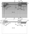
- the gear box assembly 203 is partitioned into two distinct regions defined by three plates 236a-c which support the driven shafts 212, 221, and 227 and the output shaft 230, and which are supported by support posts 245, 251.
- the first plate 236a abuts the distal facing end of the motor 90, and can be fixed to the motor's end plate.
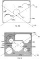
- the first plate 236a comprises two shaft holes 239a and one drive hole 242 fixed on a line D1 that runs diagonally through the center of the plate 236a connecting two of the corners.
- the drive hole 242 falls on the center of the diagonal line D1 and is sized to receive the motor output shaft 118.
- the two support shafts thus on opposite sides of the drive hole 242.
- the motor output shaft 118 protrudes fully through the drive hole 242, such that the motor output gear 121 is adjacent a forward surface of the plate 236a.
- the two shaft holes 239a are sized to fit two support posts 245, one in each hole.
- the support posts 245 support the second plate 236b spaced from the first plate 236a to define the first distinct region.
- the first distinct region is large enough to allow the motor output gear 121 to rotate freely when the motor 90 is active.
- a second diagonal line D2 runs between the other two corners of the first plate 236a and intersects the first line D1 at the center of the first drive plate 236a.
- the drive hole 242 is defined at this intersecting point.
- a smaller first drive shaft hole 248 sized to accept the first driven shaft 212 is formed on the line D2 on a first side of the drive hole 242.
- an imaginary line running through the centers of hole 248 and one of the support post holes 239a is generally parallel to a side edge of the plate 236a.
- This hole 242 receives the first driven shaft 212 on which are mounted the first driven gear 209 and the pinion gear 215.
- the hole 248 is positioned at a distance from the drive hole 242 to allow the motor output gear 121 to mesh with the first driven gear 209.
- the second plate 236b is positioned parallel to the first plate 236a and is supported by the two supports 245.
- This second plate has two shaft holes 239b positioned on two axially extending lines L1, L2 ( FIGS. 8B , C ) that run perpendicularly to the plates 236a, 236b through the center of the shaft holes 239a on the first plate 236a.
- These holes 239b are sized to allow a support post 251 to pass through, allowing the supports 245 and the shaft holes 239a in the first plate 236a to receive the base end of the support shafts 251.
- the support posts 251 could be continuations of the support posts 245.
- the support post holes 239b on the second plate 236b rest on a line D3 ( FIG.
- the second plate 236b defines a second diagonal line D4 that runs parallel to line D2.
- a notch 254 is cut out from the corner of the second plate 236b above the first driven gear 209 and pinion gear 215.
- the notch 254 defines an opening through which the pinion gear 215 extends, as seen in FIG. 7A , such that the pinion gear can extend into the second distinct region defined by the three plates 236a-c.
- a drive shaft hole is defined to receive the base end of the second driven shaft 221.
- a hole is defined at the center of the first gear set 218, sized to allow the base end of second driven shaft 221 to fully pass through prior to being received by the drive shaft hole 248.
- the first gear set 218 is allowed to freely rotate around base end of the driven output shaft 230 in the distinct second region defined by the drive box plates 236.
- the driven portion 218a of the first gear set 218 is sized to mesh with the pinion gear 215 as it passes through the notch 254 in the second drive box plate 236b.
- a second drive shaft hole 248 is defined.
- This hole receives the base end of the third driven shaft 227.
- the third driven shaft 227 extends towards the distal end of the handpiece 10 away from the second drive box plate 236b when mounted.
- the second gear set 224 is defined with a hole in the center through which the third driven shaft 227 passes prior to being secured at the base end to the second drive box plate 236b.
- the center hole on the second gear set 224 is sized to receive the third driven shaft 227 while also being free to rotate.
- the driven output gear 233 is positioned near the distal end of the first gear set 218.
- the center axis of the driven output shaft 230 is secured at the base end to the second drive box plate 236b.
- the first gear set 218, the driven output gear 233, and the driven output shaft stack in this order as the shaft extends towards the distal end of the handpiece 10.
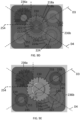
- the third plate 236c ( FIG. 9F ) is positioned parallel to the first and second plates 236a, 236b and is supported by the support posts 251. It is positioned to accept and secure the distal end of the first driven shaft 212 and the third driven shaft 227.
- a fifth diagonal line D5 that is parallel to both line D1 and line D3 runs between two corners of the plate 236c. Positioned on this line are two support shaft holes 239c and a driven output shaft hole 257.
- the two support shaft holes 239c are concentrically and colinearly aligned with the support shaft holes 239a,b of the plates 236a,b, so that lines L1 and L2 run through the centers of the two support shaft holes 239c, respectively.
- a sixth diagonal line D6 runs along the third drive box plate 236c parallel to both D2 and D4. Lines D5 and D6 intersect at a point in the center of the third drive box plate 236c.
- the driven output shaft hole 257 is centered on this intersecting point.
- the driven output shaft hole 257 is sized to receive and allow the driven output shaft 230 to pass through, so as to extend towards the distal end of the handpiece 10.
- Two drive shaft holes 248 are positioned on line D6 for accepting and securing the distal ends of the first driven shaft 212 and the third driven shaft 227. The holes are positioned so that the first driven shaft 212 and the third driven shaft 227 extend perpendicularly between the second drive box plate 236b and the third drive box plate 236c.
- the driven output shaft 230 extends from the third plate 236c of the gear box 203 towards the head of the handpiece 10 and includes an output shaft gear member 276 fixed to the distal end thereof which rotates with the output shaft 230.
- the driven output shaft has a flat keying surface 273 at its distal end extending parallel to the axis 285 of the output shaft 230.
- the center axis 285 of the output shaft gear member 276 is coaxial with the output shaft 230, such that the gear member 276 rotates about the center axis 285.
- the output shaft gear member 276 comprises a base portion 276b, a central portion 276c and a distal gear portion 276d.
- the base portion 276b defines a base end cavity 276a ( FIG. 10B ) which receives the driven output shaft 230.
- This cavity 276a is shaped correspondingly to the distal end of the output shaft 230, such that the gear member 276 will be rotationally fixed to the output shaft 230.
- the cavity 276a has a flat wall 277 which engages the flat surface 273 of the output shaft 230 to rotationally fix the output shaft gear member 276 relative to the output shaft 230.
- the central portion 276c of the gear member is positioned between the distal end of the base portion 276b and the base end of the distal gear portion 276d.
- the radius of the central portion 276c is smaller than the radius of the base portion 276b, and thus defines a step.
- the central portion 276c has a generally smooth exterior.
- a driving axis bracket 279 ( FIGS. 13A, B ) is positioned about the central portion 276c of the output shaft gear.
- the driving axis bracket 279 is shaped as a ring that encircles the central portion 276c of the gear member 276.
- the driving axis bracket 279 is positioned in the handpiece housing between a bottom surface of the housing and the light PCB 93, and thus operates as a journal bearing which helps fix the relative position the output shaft gear member 276 in the head of the handpiece.
- the driving axis bracket 279 is sized (i.e., has a front-to-back width) such that the distal gear portion 276d will protrude beyond the distal surface of the driving axis bracket 279.
- a light guide receiving gear member 282 ( FIG. 11 ) is positioned in the head 13d of the handpiece to rotate about an axis which intersects the axis of the output shaft gear member 276.
- the light guide receiving gear member 282 is generally perpendicular to the output shaft gear member 276.
- the two gear members could define other angles, if desired.
- the light guide receiving gear member 282 ( FIG. 11 ) comprises a hollow central sleeve 282c and an annular flange 282a which extends from the approximate center of the sleeve. Teeth 282e on the annular flange 282a form a gear on an upper surface of the flange 282a.
- the sleeve extends both above and below the flange to define a top portion 282b and a bottom portion 282d of the sleeve.
- the top portion 282b extends towards the top cover 10a of the handpiece 10 from the gear portion 282a.
- the top portion 282b of the gear sleeve 282 is stepped, to define a portion 282f of reduced diameter.
- the sleeve 282c defines a passage 282g which, as described below, will receive a stem of a light guide, and through which light from the light source 94 will pass.
- the light source 94 is positioned on an axis of the light guide holder to direct light directly to the light guide.
- handpiece could be configured in different ways such that the light from the light source is directed to the stem of the light guide.
- the handpiece could be provided with a light tube (i.e., a fiber optic) which directs light from the light source to the stem of the light guide, thereby allowing the light source to be positioned in any desired location in the handpiece.
- the light guide holder could be made of light transparent material, and the light could pass through the sleeve of the light guide holder into the light guide. In this example, the light can be directed at the sleeve of the light guide holder from most any angle.
- the gear members 276 and 282 are positioned in the head so that their respective teeth mesh, such that the output shaft gear member 276 will drive the light guide receiving gear member 282.
- a gear sleeve cover 291 ( FIGS. 12A-D ) is positioned in the head of the handpiece. The gear sleeve cover, in part, serves to maintain the positions of the gear members 276 and 282 relative to each other so that they will mesh, and thus transition the horizontal rotational/reciprocal motion of the output shaft to vertical rotational/reciprocal motion.
- the gear sleeve cover 291 comprises a base portion 291a, an upper portion 291b, a top surface 291g that faces the top shell 10a, and a bottom surface 291h that faces the bottom shell 10b of the handpiece 10.
- a cylindrical through passage 291c sized to receive the reduced diameter portion 282f of the light guide receiving gear member 282 extends between the top surface and the bottom surface.
- the passage 291c is generally cylindrical in shape with the center positioned to extend parallel to the axis 288 of the light guide receiving gear member 282.
- the base portion 291a is generally in the shape of a flattened omega ( ⁇ ) or a flattened horseshoe.
- the base portion of the gear sleeve cover comprises opposed arced side portions 292a which have flat end surfaces 292b extending between the distal ends of the side portions.
- the wall 292c joining the side portions is flat.
- the outer surface of the side portions 292a are arced and define a radius.
- a pair of spaced apart arms 292f which extend rearwardly from the flat distal surfaces 292b of the side portions. As seen, the arms 292f extend generally from a midpoint of the flat end surfaces 292b.
- the space 292d between the side portions defines an opening into the passage 291c.
- the space 292d is sized to permit passage of the geared portion 276d of the output shaft gear member 276.
- the portion of the flat end surface 292b between the arms 292f and the opening 292d define a stop to prevent the gear member 276 from extending too far into the central opening 291c.
- the upper portion 291b of the gear sleeve cover continues the flattened omega shape of the base portion.
- the upper portion comprises opposed arced side walls 293a, the exterior of which define a radius, and which have flat end surfaces 293c.
- a side wall 293d extends rearwardly from each of the end surface surfaces 293c of the upper portion 291b.
- the side walls 293d are connected by an arched surface 293e and by the top surface 291g, effectively forming an arched passage leading into the entrance 292d to the passage 291c of the gear sleeve cover.
- the side walls 293d of the top portion as seen best in FIG. 12A , are atop the arms 291f of the base portion and are shorter than the arms 291f of the base portion. Thus, the arms 291f protrude from beneath the walls 293d.
- a cutout 295e defined by a dashed rectangular region in FIG. 12D , extends rearwardly from the flat distal surface of the top portion 291b to a point approximately even with the end surface 293c of the arced wall 293a of the top portion 291b.
- This cutout is open to the top surface, and thus defines a generally rectangular cavity that opens towards the distal end of the top portion.
- a positioning tooth 292f extends upwardly between the opposite sides of the cutout at the distal end of the top portion, as shown in FIGS. 12A and 12D .
- the gear sleeve cover 291 can also be seen as being in the shape of a flattened igloo.
- the igloo comprises a main body comprised of the base and upper portion 291a, b and an arched doorway, defined by the arms and walls 292e, 293df, and 292gd.
- the upper and lower portions thus define a stacked cylinder configuration, with the bottom cylinder having a larger radius than the top cylinder.
- the center axis 288 of the cover 291 best shown in FIG. 12B as a dashed line, and FIGS.
- the stacked cylinder configuration of the main body comprises the flat end surfaces 292b at the front which lies in a plane parallel to the axis 288.
- the space between the flat end surfaces 292b define the entryway 292d to the passage.
- An arched doorway of the flattened igloo shape extends generally perpendicularly away from the flat surface 292b.
- the arched doorway is defined by the side members 292f, 293c, top surface 291g, and front surface 292g to create a tunnel-like entrance.
- the archway or tunnel-like entrance 291e defines an entrance passage to the entryway 291d which leads into the cylindrical passage 291c.
- the gear sleeve cover and light board 93 are positioned such that the passage 291c is aligned with the light source 94. Further, as seen in FIGS. 5B and 13A , the passage 291c is sized to receive the light source 94, such that light from the light source 94 will shine through into passage 291c from the top surface 291g of the cover in a direction towards the bottom surface 291h of the main body portion 291a.
- the passage 291c is sized to receive the top portion 282b of the light guide receiving gear member 282.
- the top portion 282b of the light guide gear member 282 extends into the base portion 291a from the bottom of the cover, but does not extend into the upper portion 291b of the gear sleeve cover (which is occupied, in part, by the light source 94).
- the radial surface defined by the step in upper portion 282b of the sleeve 282c of the light guide receiving gear member acts as stop to prevent further insertion into the passage 291c of the cover. As seen in FIG.
- the teeth 282e on the flange 282a of the gear member 282 define a circle, the circumference of which is positioned under the arms 291f extending from the base portion 291a of the gear sleeve cover 291, such that the teeth 282e of the gear member 282 face upwardly towards the bottom surface 291h.
- the entryway 291d of the gear sleeve cover is sized to receive the gear portion 276d of the output shaft gear member 276.
- the gear portion 276d of the output shaft gear member 276 extends between the arms 291f of the base portion 291a.
- the annular ring bracket 279 is adjacent the distal surface of the arms 291f on the central portion 276c driving axis gear member to prevent the gear portion 276d from entering the passage 291c, such that the gear portion 276d will mesh with the teeth 282e of the gear member 282.
- the gear sleeve cover 291 When the handpiece 10 is assembled with the top shell 10a and the bottom shell 10b pressed together, the gear sleeve cover 291 provides component alignment support for the head gear assembly (i.e., the gear members 276 and 282). The alignment of the base portion 291a and the upper portion 291b with the central axis 285 and the perpendicular axis 288 secure the driving components into place.
- the light source 94 is received in the top of the passage 291c of the gear sleeve cover 291.
- the top portion 282b of the light guide receiving gear member as noted, is received in the passage 291c through the bottom surface 291h of gear sleeve cover 291.
- the gear members 276 and 282 can be made of a plastic or from metal.
- the bottom shell 10b defines inner surfaces which axially position the gear member 282 within the handpiece head to align with the opening 14 in the bottom surface of the handpiece head.
- a gear ring 294 is positioned about the bottom portion 282c of the gear sleeve 282 below the bottom surface of the flange 282a. As seen, for example in FIG. 13A , the gear ring 294 is positioned in a seat 10d in the housing bottom shell 10b between the flange portion 282a and the bottom surface of the head.
- the gear ring 294 provides a low friction surface to facilitate rotation of the gear member 282 within the head.
- the gear member 282 is thus securely fit into the assembled handpiece 10 so that it is free to rotate when the motor 90 is activated but is secured and protected from additional vibrations that may otherwise cause damage.
- the gear sleeve cover 291 is described as an individual component, which is positioned in the top shell 10a, b of the housing 13.
- the top and bottom shells 10a, b of the housing could be formed (molded) to define the surfaces which receive the gear members 276 and 282 and bring them into meshing contact with each other. Further, such molding could align the light source 94 with the passage 291c, such that the light from the light source 94 shines down, into the passage 291c. Housing shells configured in this manner would obviate the need for a separate cover 291.
- Each light guide comprises a circular disc-shaped base plate 104, a stem 102 extending upwardly from the base plate 104 and a respective probe 106A-I extending downwardly from the base plate 104.
- the base plate 104 is generally disc-shaped with a radius approximately equal to the radius of the bottom head surface. As such, the base plate portion 104 serves as a shield to reduce the potential for fluids, bacteria, etc. from splashing up into the head through the opening 14.
- the stem 102 is sized to be frictionally received in the cylindrical passage 282g of the light guide receiving gear member. When received in the handpiece head, the disc 104 will be adjacent the bottom of the handpiece head.
- each light guide is generally cylindrical, but tapers slightly from the base 104upwardly.
- a plurality of fins 106 extend upwardly from the base 102 and are spaced (preferably equiangularly) about the exterior surface of the stem. The fins increase the radius of the stem sufficiently to form a frictional fit of the stem within the gear member sleeve to positionally secure the light guide to the gear member 282.
- the light guide will be securely positioned with the head gear assembly to be rotationally driven when the motor is activated.
- the stem passes through the head opening 14 into the cylindrical passage 282d of the gear member 282, and the base 104 of the light guide is below the bottom surface of the handpiece head.
- Each light guide 100A-I has an associated shield or cover 120A-I that is affixed to the disc 103of the respective light guide.
- the cover 120A-I provides additional protection and shielding to the light guide 100A-I, the opening 14 in the head of the handpiece, and the internal driving gear assembly when the handpiece 10 is in use.
- the cover 120A-I is opaque, and thus substantially prevents light from the light source from exiting the base 104 of the light guide, such that all light passes through the tip of the light guide.
- Each light guide cover 120A-I includes an attachment portion 122 sized to enclose the periphery of the base 104 of the light guide 100A-I.
- the attachment portion 101a is generally puck-shaped with a bottom surface 122a and a circumferential side wall 122b extending upwardly from the bottom surface, which in combination define cavity which is receives the base 104 of the light guides 100A-I in a secure fit such that the cover 120A-I will rotate with the light guide 100A-I if used with the motor is activated.
- the cover 120A-I is preferably made from a flexible/pliable material, so that the attachment portion 122B of the cover 122 can be fitted about the base 104 of the light guide 100A-I.
- a hollow nose 130A-I, particular for each light guide, extends from the attachment portion 122, and the probe 106A-I extends, at least in part, through the nose 130A-I.
- the light guides are made from a light transmissive (and preferably light transparent) material.
- the base 104 need not be made from a light transmissive material (so long as there is a continuous light path from the top of the stem 102 to the top of the probe 106A-I.
- the stem 102 of the light guide is axially aligned with the light source 94.
- the light source 94 when activated, will thus direct its light into the passage 291C of the cover 291 to enter the stem 102 of the light guide at the top of the stem.
- the light guide defines a continuous light path from the top of the stem to the probe 106A-I.
- the light will travel down the stem 102 into the probe 106A-I to exit the probe 106A-I through either or both of the bottom and sides of the probe.
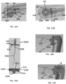
- a first light guide 100A is shown in FIGS. 14A-C .
- the probe 106A of the light guide 100A is designed to extend substantially to the apical end of a root canal.
- the light guide 100A includes a short connecting section 108A which transitions between the probe 106A and the base 104.
- the nose 130A of the cover 120A is sized to encase this connection section, and the probe 106A extends from the end of the nose. Thus, light will exit the probe 106 through the sides and bottom of the probe.
- the probe 106A can be used to mechanically or dynamically activate fluid in a root canal (or other treatment area). As such, it is an "active" probe which is rotationally or reciprocally driven by the drive mechanism of the handpiece.
- the light guide 100A can be used to transilluminate a tooth from within the root canal when the canal is free of liquid. This will facilitate in the visualization of cracks in the root of the tooth.
- the light guide 100A When used to transilluminate a tooth, the light guide 100A will be used as a static probe (i.e., non-rotating), and thus will be used without engaging the motor.
- the probe 106A is made in accordance with the tip shown and described in US Pub. No. 2019/0290397 and has an S or spiral shape.
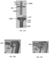
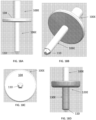
- a second light guide 100B is shown in FIGS. 15A-C .
- the probe 106B of this light guide defines cylindrical post extending downwardly from the base 104. Although shown with a flat bottom surface, the probe could have a rounded or curved bottom surface. The distal end could also be faceted.
- the nose 130B of the cover 120B extends the full length of the probe 106B. As such, light only exits through the end of the probe 106B.
- the probe 106B is designed for external use to transilluminate the tooth crown and to cure pre-endodontic and post endodontic restoration materials.
- the probe 106B can be used to illuminate select tissue areas (i.e., of the gum or check), and thus, when used with a light of the proper wavelength, can be used to detect certain cancers, such as oral cancer.
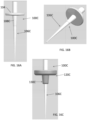
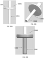
- a third light guide 100C is shown in FIGS. 16A-C .
- the probe 106C of the light guide 100C is an elongate tapering probe sized and shaped to extend to the apical end of a root canal.
- the probe can, for example, be 20mm long.
- the probe 106C includes an upper tapered connection section 108C which connects the probe 106C to the base plate 104.
- the nose 130C of the cover 1200 is sized and shaped to encase the connecting portion 1080.
- the light guide 100C can be used to transilluminate a tooth root from within the root canal to facilitate detection of cracks and other abnormalities in the tooth root. As such, the light guide 100C is primarily intended to be a static guide. However, it could be driven in the canal by the motor to activate fluid within the canal.
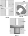
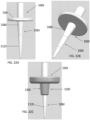
- a fourth light guide 100D is shown in FIGS. 17A-C .
- the probe 106D of the light guide 100D is generally cylindrical with a flat bottom surface. However, it is shorter and wider than the light probe 100B.
- the light probe 106D can have a length of 5mm and a width of 4mm (for a L:W ratio of 5:4).
- the nose 130D of the cover 120D extends the full length of the probe 106D, and thus, the light will exit primarily through the end of the probe.
- the sides of the probe and the surfaces of the base plate 104 can be coated with a light-opaque material, such as a silicon or a metallic coating.
- the light guide 100D is intended for use as an illumination light guide to provide illumination with a mouth or treatment area, transilluminate the crown externally, and to cure materials, such as restoration materials and cavity filling materials.
- the width of the probe 106D will allow the probe to be inserted into access cavities in crowns of certain teeth (for example, molars), and could be used to transilluminate a crown from within the access cavity.
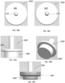
- a fifth light guide 100E is shown in FIGS. 18A-C .
- the probe 106E of the light guides 100E is cylindrical, with a long narrow profile.
- the light probe 106E can have a length of 10mm and a width of 2mm (for a L:W ratio of 5:1).
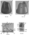
- the probe 100E differs in that it has an end portion 110E in the form of a prism at the distal end of the probe.
- the prism 110E is illustratively shown to have a flat bottom surface in the shape of a pentagon, with walls sloping upwardly and outwardly form each edge of the base.
- the nose 130E of the cover 120E extends the length of the probe, such that just the prism 110E extends from the end of the nose 130E. Light thus exits the light through the facets (bottom and sides) of the prism 110E.
- the diameter of the probe allows for the probe to extend at least partially into a prepared root canal.
- the probe 106E can thus be used to transilluminate the tooth root and the tooth crown and to cure materials in the root and crown.
- the light guide 100E is primarily a static light guide.
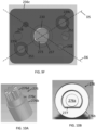
- FIGS. 18E-F show two variations of the light guide 100E.
- the light guides of FIGS. 18E-F are identical to the light guide of FIGS. 18A-D , except for the prism at the distal end of the probe. If FIG.
- the prism is hexagonal and in FIG. 18F , the prism is octagonal. As seen in FIGS. 18D-F , bottom surfaces of the prisms all define regular polygons. By changing the number of side surfaces of the prisms, the direction the light is transmitted will be altered slightly.
- a sixth light guide 100F is shown in FIGS. 19A-C .
- the probe 106F of the light guide 100F is cylindrical with a flat bottom surface.
- the light probe 106F can have a length of 2mm and a width of 8mm (for a L:W ratio of 1:4).
- the probe 106F is generally a squat or blunt probe.
- the nose 130F of the cover 120E surrounds full side wall of the probe 106F such that light exits primarily through the bottom of the probe.
- the large diameter of the probe renders the probe too large to fit into the access cavity of a tooth.
- the material from which the cover 120F is made is malleable or conformable.
- the cover when the probe is be pressed against the upper surface of a tooth or access cavity, the cover will conform to the shape of the tooth rim to form a seal with the tooth rim. This will allow for the probe to be used to transilluminate the access cavity or crown of the tooth from within, to facilitate detection of cracks within the tooth.
- the light guide can be used to illuminate soft tissue (i.e., check or gum tissue) to detect abnormalities in the soft tissue, including certain oral cancers.
- a seventh light guide 100G is shown in FIGS. 20A-C .
- the probe 106G of the light guide 100G defines a generally elongate cylinder.
- the bottom surface of the probe 106G is shown to be flat, but could be rounded or faceted.
- the probe 106G is sized to fit into a canal to reach the apical end of the canal.
- the probe thus has a diameter of 2mm or less and a length of 15-20mm.
- the nose 130G of the cover 120 extends the full length of the probe 106G, such that light primarily exits the bottom of the light probe 106G.
- the probe 106G can be used to direct light into a root canal to illuminate only portions of the canal below the distal end of the probe. This will allow the practitioner to study individual areas of the root canal to, for example, better determine where a crack begins and ends. Additionally, the probe 106G can be used to cure materials within the canal or in the access cavity.
- FIGS. 21A-D An eighth light guide 100H is shown in FIGS. 21A-D .
- the light probe 106H of the light guide 100H is generally cylindrical and comprises an upper portion 110H which depends generally perpendicularly from (normal to) the base 104.
- a lower portion 112H angles extends from the distal end of the upper portion at an angle of about 30°-60°, and preferably about 40°-50°.
- an end portion 114H extends from the distal end of the probe's lower portion 12H.
- the end portion 114H is shown to be a tapering triangle. That is, it has a triangular base at the distal end of the probe 106H, and the three sides of the triangle taper to a point.
- the nose 130H of the cover 120H extends the length of the probe, such that only the end portion 114H extends from the end of the nose 130H.
- the end portion 114H tapers to a size that permits the end portion to be used interproximally (i.e. to fit between adjacent teeth) and to extend slightly into the periodontal pocket.
- This probe 106H can thus be used to transilluminate to tooth crown to detect cracks in the crown and to transilluminate the gum surrounding the tooth to visualize bone in the gum. This facilitates monitoring bone loss in patients with periodontal disease.
- the end portion 114H is shown as a triangle, the end portion 114H could be a flexible narrow cylinder which can fit between the teeth.
- a ninth light guide 100I is shown in FIGS. 22A-C .
- the probe 106I of the light guide 100I is an elongate tapering probe sized and shaped to extend into a gingival pocket. The distal end of the probe is thus preferably rounded to provide smooth surface to reduce the potential for scratching the gingival tissue in the pocket.
- the probe 106I includes an upper tapered connection section 108I which connects the probe 106I to the base plate 104.
- the nose 130I of the cover 120I is sized and shaped to encase the connecting portion 1081.
- the light guide 100I can be used to transilluminate a gingival pocket from within the pocket. This allows for the practitioner to visualize bone level and tooth attachment apparatus and to detect cracks in the tooth.
- the light guide 100C is primarily intended to be a static guide. Additionally, the probe includes markings 112I spaced at even intervals, for example 5mm. The probe 100I can thus be used to measure the depth of a periodontal pocket.
- the probe 106I has a single marking 112I spaced midway between the distal end of the probe and the bottom of the nose 130I of the cover.
- FIGS. 22D-E show longer versions of the probe.
- the probe 106I' includes two marks 112I; and the probe 106I" includes three marks 112I.
- the probes 106I, 106I' and 106I" can have varying lengths (e.g. of 10mm, 15mm, 20mm).
- some of the light guides can be used to locate the canal orifice at the base of the pulp chamber.
- a fluorescent dye such as rose bengal
- the practitioner can apply a fluorescent dye (such as rose bengal) in the pulp chamber, gently rinse the pulp chamber, and then illuminate the floor of the pulp chamber using an appropriate light guide with an appropriate light wavelength (such as green light).
- the fluorescent dye in the orifice will light up - guiding the clinician to the root canal that leads from the orifice.
- the light probes can be grouped as active light probes (i.e., those which are intended to be rotatably or reciprocatingly driven, and static light probes (i.e., those which are intended to be used only transmit light, and thus are used without engaging the motor).
- active light probes i.e., those which are intended to be rotatably or reciprocatingly driven
- static light probes i.e., those which are intended to be used only transmit light, and thus are used without engaging the motor.
- the side wall of the probes can be fully covered by the nose of the cover, so that light exits only the end of the probe, or the probes can extend from the nose, so that light can be transmitted from the sides of the probes.
- the probes can be provided with end portions (prisms) which allow for the light to be directed outwardly, rather than axially.
- portions of any of the light guides can be coated with a light opaque material to direct light to exit the probe only through specific areas of the probe.
- the side wall of the probe and the base plate 104 can be coated. If the coating is reflective, the coating will facilitate directing the light to desired exit points on the probe.
- the coating can block virtually 100% of the light, so that light cannot pass through the coating, such that light exits the light guide only in coating free areas.
- the coating can be one which allows for a desired fraction of the light to pass through.
- an upper portion of the probe can be provided with a coating that blocks, for example, 50% of the light, and a bottom portion of the probe can be uncoated.
- Coatings can be applied via injection molding on (or even co-molding with) the probe, or can be applied via 3D printing, sputtering, vapor deposition, electrostatic deposition, or any other desired method.
- the handpiece battery is described to recharge wirelessly, the handpiece could have external electrical contacts on its bottom surface 13e which engage corresponding electrical contacts in the floor 33b of the charging base, such that the handpiece has a wired, rather than wireless, connection to the recharging base. Further, the handpiece could be wired, rather than cordless. In this instance, the battery could be omitted, and replaced with a power cord which would connect the handpiece to a source of electricity.
- the light guide is described to be frictionally received in the light guide holder/gear member 282, the light guide can be secured in the light guide holder by other means.
- the light guide can be threaded into the light guide holder, the light guide and light guide holder can include a pin and a bayonet slot. Any other connection means can be used that will rotationally fix the light guide to the light guide holder. These examples are merely illustrative.
Landscapes
- Health & Medical Sciences (AREA)
- Life Sciences & Earth Sciences (AREA)
- Oral & Maxillofacial Surgery (AREA)
- Public Health (AREA)
- Animal Behavior & Ethology (AREA)
- General Health & Medical Sciences (AREA)
- Veterinary Medicine (AREA)
- Dentistry (AREA)
- Epidemiology (AREA)
- Surgery (AREA)
- Engineering & Computer Science (AREA)
- Biomedical Technology (AREA)
- Nuclear Medicine, Radiotherapy & Molecular Imaging (AREA)
- Pathology (AREA)
- Biophysics (AREA)
- Medical Informatics (AREA)
- Heart & Thoracic Surgery (AREA)
- Molecular Biology (AREA)
- Physics & Mathematics (AREA)
- Radiology & Medical Imaging (AREA)
- Optics & Photonics (AREA)
- Neurology (AREA)
- Neurosurgery (AREA)
- Audiology, Speech & Language Pathology (AREA)
- Water Supply & Treatment (AREA)
- Dental Tools And Instruments Or Auxiliary Dental Instruments (AREA)
- Dental Preparations (AREA)
Description
- This invention relates to medical/dental handpieces, and in particular, to a handpiece adapted to receive a light guide to deliver light into a treatment area (such as a root canal, a prepared cavity in a tooth crown, periodontium, or interdental spaces) to facilitate diagnosis (such as tooth cracks and bone loss) and treatment (such as photodynamic therapy and tooth restoration) of the treatment area. The light guide can be static, in which case it only directs light of a desired wavelength and intensity to the treatment area, or active, in which case it can dynamically (mechanically) activate fluids in the treatment areas.
-
US 2019/290397 A1 discloses a system used for the irrigation and disinfection the root canal including a driver (motor) and tip. The system includes light excitation sources for visual enhancement and also wavelengths used in photo-dynamic therapy. The light can be routed into the back of the rotating tip and the light travels through the tip material and exits through the surface of the material into the root canal. - During photodynamic therapy of a root canal has been proposed. Such treatment includes introducing a photoactive solution to the root canal, and introducing light into the root canal to then activate the photoactive compound in the solution.
US Pat. No. 9987200 - What is needed is a handpiece that can deliver light into a treatment area, such as the root canal and/or periodontium, to activate a photosensitive compound and/or mechanically activate the solution to enhance treatment of the treatment area. In addition, such a handpiece could be used to facilitate diagnosis of, for example, tooth cracks, bone loss, and caries and in the procedures of apical surgeries such as Root End Resections (RER), Root End Preparations (REP), osteotomies and biopsies.
- Disclosed herein is a medical/dental handpiece and associated light guides which can be used for both diagnosis and treatment of, for example, dental issues. For example, the handpiece and associated light guides can be used for detection of tooth cracks, locating the orifice at the base of the pulp chamber, locating calcified and/or blocked canals within the roots of teeth, determination of bone loss in the gums, detection of certain cancers, treatment of root canals, caries, and restoration of teeth. Although the handpiece is described below for use with dental procedures, it will be apparent that the device can also be used for medical procedures.
- Briefly stated, a medical/dental handpiece, comprises a housing having a head portion, a motor selectively switchable between an activated mode in which its output shaft rotates or reciprocates and an deactivated mode in which its output shaft neither rotates nor reciprocates, an output shaft gear member operatively driven by the motor, a light source comprising at least one or more light producing elements selectively switchable between an activated mode in which the light source produces light, and a deactivated mode in which the light source does not produce light, and a light guide holder mounted in the head of the handpiece for rotation relative to the head. The light guide holder comprises a sleeve and a circumferential flange on the sleeve teeth on an upper surface thereof to define a light guide holder gear. The sleeve further defines a passage therethrough which is axially aligned with an opening in the bottom surface of the head and the light source, whereby when activated, light from the light source will be directed toward the passage of the light guide holder. The light guide holder and the output shaft gear are positioned in the housing such that the output shaft gear drives meshes with the teeth of the light guide holder, such that when the motor is activated, the light guide holder will be driven by the output shaft gear. A light guide comprises a stem and a probe below the stem, the stem being sized to be removably received in the sleeve of the light guide holder such that the light guide will be driven by the light guide holder upon activation of the motor. The light guide being made at least in part of light transmitting material, whereby the light guide receives the illumination from the light source when the light source is activated, and the illumination passes through the light guide stem to exit through the probe of the light guide. Lastly, the handpiece includes a control circuit for the handpiece; the control circuit comprising the motor, the light source, and at least one switch, such that the handpiece is operable in three modes: (1) only the motor is activated, (2) the light source is activated, and (3) both the motor and light source are activated.
- In accordance with an aspect of the handpiece, the light source can be a dedicated light source (i.e., to operate at a single wavelength or intensity) or it can be configured to change the wavelength and/or intensity of the light produced by the light source. Whether the light source is a dedicated light source or a variable light source, the light source can comprise a single light producing element or two or more light producing elements.
- In accordance with an aspect of the handpiece, the light source comprises a plurality of discrete light producing elements, and the control circuit is configured to selectively activate only one of the discrete light producing elements or selectively activate two or more of the discrete light producing elements. In one variation, the plurality discrete light producing elements include at least two light producing elements which emit light in different wavelengths; and in another variation, the plurality of discrete light producing elements include at least two light producing elements which emit light at the same wavelength.
- In accordance with an aspect of the handpiece, the light guide can include a coating at least on walls of the probe. The coating can be a coating which permits no light to pass through the coating or which permits a desired amount of the light to pass through the coating such that light exits the light probe only at desired portions or intensities of the light probe. The coating can be, for example, a silicon coating or a reflective metal coating.
- In accordance with an aspect of the handpiece, the light guide can comprise a plate between the stem and the probe which is positioned adjacent an outer surface of the bottom surface of the head when the light guide is received in the light guide holder. The handpiece can further comprise a cover comprising an attachment portion adapted to be connected to the plate of the light guide and a nose which extends from the attachment portion; the nose at least in part surrounding the probe.
- In accordance with an aspect of the handpiece, the cover is made from a flexible and conformable material such that when pressed against a surface; the protective sleeve will conform to the shape of the surface.
- The probe can have different configurations. For example:
- the probe can taper along a length of the probe and be sized to extend into a prepared root canal, an access cavity, clinical crown or a periodontal pocket adjacent a tooth.
- the probe can include at least one measurement marking along the length of the probe.
- the probe can be shaped to mechanically activate fluid in a root canal or cavity upon activation of the motor.
- the probe can be generally cylindrical in cross-section.
- the probe can include an end portion on a distal end of the probe, wherein:
- the end portion comprises a prism having an end surface in the form of a polygon and side surfaces extending from edges of the end surface to the distal end of the probe.
- the end portion is sized and shaped to be received in spaces between teeth or in periodontal pockets.
- the end portion comprises a triangular prism extending from the distal end of the probe.
- the probe can define an upper section and a lower section, wherein, the lower section angles away from the upper section.
- In accordance with an aspect of the handpiece, the nose of the cover can extend substantially the full length of the probe, such that substantially only the end portion of the probe extends beyond the nose, such that light exits substantially only through the end portion.
- In accordance with an aspect of the handpiece, the probe has a diameter sized to enable the probe to extend into a tooth root canal.
- In accordance with an aspect of the handpiece, the probe has a diameter sized such that cover will engage and cover an upper surface of a tooth when the probe is positioned on a tooth.
- In accordance with an aspect of the handpiece, the handpiece further comprises an output shaft extending from the motor, the output shaft gear being at an end of the output shaft spaced from the motor; the output shaft being rotatable about an output shaft axis; and wherein the light guide holder is rotatable about a light guide holder axis that is offset from the output shaft axis.
- In accordance with an aspect of the handpiece, the handpiece comprises a first bearing surface and a second bearing surface in the head of the handpiece. The first bearing surface defines an arc in a plane generally perpendicular to the output shaft axis; the output shaft gear member defines a shoulder which rotates against the first bearing surface; and the second bearing surface being generally cylindrical and being sized to rotatably receive an upper portion of the sleeve of the light guide holder.
- In accordance with an aspect of the handpiece, that handpiece includes a gear cover received in the head of the handpiece, wherein the gear cover defines the first and second bearing surfaces. The gear cover has an upper surface defining an opening aligned with the sleeve of the light guide holder; the light source being positioned to direct illumination through the opening.
- In accordance with an aspect of the handpiece, the handpiece includes a gear box assembly positioned between the motor and the output shaft, wherein the torque reduction assembly comprises a plurality of intermeshing gears which reduce a torque and increase speed output by the motor to a desired torque and speed.
- In accordance with an aspect of the handpiece, the handpiece comprising:
- a housing having a base portion, a central portion, distal portion, and a head portion at an end of the distal portion; the head portion having a bottom surface defining an opening;
- a motor contained within the housing;
- an output shaft operatively connected to the motor to be driven by the motor; the output shaft rotatable about an output shaft axis;
- an output shaft gear rotationally fixed to the output shaft to be driven by the output shaft, wherein the output shaft gear comprises a distal gear portion,
- a light guide holder rotatably mounted in the head; the light guide holder comprising a hollow sleeve defining a passage therethrough, a circumferential flange on the sleeve having teeth on an upper surface of the flange to define a light guide holder gear; the light guide holder gear being positioned in the head such that the sleeve is axially aligned with the opening in the bottom surface of the head; the light guide holder being rotatable about a light guide axis which is offset from the output shaft axis;
- a first bearing surface and a second bearing surface in the head of the handpiece; the first bearing surface defining an arc in a plane generally perpendicular to the output shaft axis; the output shaft gear defining a shoulder which rotates against the first bearing surface; and the second bearing surface being generally cylindrical and being sized to rotatably receive an upper portion of the light guide holder sleeve; the first and second bearing surfaces positioning the output shaft gear and the light guide holder gear such that they mesh, wherein the light guide holder gear is rotationally driven rotationally by the output shaft gear; and
- a light source positioned in the handpiece; the handpiece being configured to direct light into the light guide holder sleeve when the light source is activated.
- In accordance with an aspect of the handpiece, the first and second bearing surfaces are defined by a gear sleeve cover; the gear cover having an upper surface defining an opening aligned with the sleeve of the light guide holder; the light from the light source being directed through the opening.
- In accordance with an aspect of the handpiece, the light guide holder is driven by the output shaft gear about an axis that is distinct from the axis of the output shaft gear.
- In accordance with an aspect of the handpiece, the light guide holder is driven rotationally and/or reciprocatingly.
-
-
FIG. 1A is a front elevational view of an endodontic handpiece with a light guide mounted in a head thereof and set in a charging base; -
FIG. 1B is a rear elevational view of the handpiece in the charging base; -
FIG. 1C is a perspective view of the handpiece with a light guide mounted in the head; -
FIG. 1D is a rear elevational view of the handpiece; -
FIG. 1E . is a bottom plan view of the handpiece; -
FIG. 2 is an exploded perspective view of the handpiece and charging base; -
FIG. 3 is a cross-sectional view of the handpiece and charging base taken along line 3-3 ofFIG. 1A ; -
FIG 4A is a front perspective view of the charging base; -
FIG. 4B is a rear perspective view of the charging base; -
FIG. 4C is a cross-sectional view of the charging base; -
FIG. 4D is an exploded view of the charging base; -
FIG. 5A is a side view of a drive mechanism and light source of the handpiece with a light guide; -
FIG. 5B is a partial cross-sectional view of the drive mechanism and light source with a light guide; -
FIGS. 6A and 6B are exploded elevational and perspective views, respectively, of the drive mechanism of the handpiece with the light source and a light guide; -
FIGS. 7A and 7B are fragmentary perspective views of a gear box assembly of the drive mechanism; -
FIGS. 8A, 8B , and8C are cross-sectional views of the gear box assembly along a direction parallel to the axis of the motor output shaft, taken along parallel planes passing through different driven shafts of the gear box assembly; -
FIG. 9A is a cross-sectional view of the gear box assembly taken along line A-A ofFIG. 7B looking rearwardly at a first plate of the gear box assembly; -
FIG. 9B is a cross-sectional view of the gear box assembly taken along line B-B ofFIG. 7A spaced forwardly of line A-A and looking rearwardly at the first plate of the gear box assembly; -
FIG. 9C is a cross-sectional view of the gear box assembly taken along line C-C ofFIG. 7B looking rearwardly at a second plate of the gear box assembly; -
FIGS. 9D-E are a cross-sectional views of the gear box assembly taken along parallel, but axially spaced apart, planes D-D ofFIG. 7A and E-E ofFIG. 7B , respectively looking rearwardly at the second plate of the gear box assembly; -
FIG. 9F is a cross-sectional view of the gear box assembly taken along line F-F ofFIG. 7A looking rearwardly at a third plate of the gear box assembly; -
FIGS. 10A-B are perspective and bottom plan views of a gear member mounted at the end of an output shaft of the drive mechanism; -
FIGS. 11 is a perspective view of a light guide receiving gear member which is mounted in the head of the handpiece; -
FIGS 12A-12D are top perspective, front elevational, bottom plan, and top plan views of a gear sleeve cover of the handpiece; -
FIG. 13A is a fragmentary cross-sectional view of a portion of the drive mechanism in the head of the handpiece with a light guide received in the light guide receiving gear member; -
FIGS. 13B is an elevational view showing the interconnection of the output shaft gear member and the light guide receiving gear member with the gear sleeve cover shown in phantom; -
FIGS. 13C and 13D are fragmentary perspective views of the portion of the drive mechanism in the head of the handpiece with the housing of the handpiece shown in phantom; -
FIG. 14A is an exploded elevational view of a first light guide and an associated cover; -
FIGS. 14B and 14C are fragmentary side elevational and cross-sectional views of the head of the handpiece with the first light guide; -
FIG. 15A is an exploded elevational view of a second light guide and an associated cover; -
FIGS. 15B and 15C are fragmentary side elevational and cross-sectional views of the head of the handpiece with the second light guide; -
FIGS. 16A-B are elevational and bottom perspective views, respectively of a third light guide; -
FIG. 16C is an elevational view of the third light guide with an associated shield; - .
FIGS. 17A-B are elevational and bottom perspective views, respectively of a fourth light guide; -
FIG. 17C is an elevational view of the fourth light guide with an associated shield; -
FIGS. 18A-C are elevational, bottom perspective, and bottom plan views, respectively of a fifth light guide; -
FIG. 18D is an elevational view of the fifth light guide with an associated shield; -
FIGS. 18E-F are bottom plan views showing variations of the distal end of the fifth light guide -
FIGS. 19A-B are elevational and bottom perspective views, respectively of a sixth light guide; -
FIG. 19C is an elevational view of the sixth light guide with an associated shield; -
FIGS. 20A-B are elevational and bottom perspective views, respectively of a seventh light guide; -
FIG. 20C is an elevational view of the seventh light guide with an associated shield; -
FIGS. 21A-C are elevational, bottom perspective, and front perspective views, respectively of an eighth light guide; -
FIG. 21D is an elevational view of the eighth light guide with an associated shield; -
FIGS. 22A-B are elevational and bottom perspective views, respectively of a ninth light guide; -
FIG. 22C is an elevational view of the ninth light guide with an associated shield; and -
FIGS. 22D-E are elevational views of variations of the ninth light guide. - Corresponding reference numerals will be used throughout the several figures of the drawings.
- An illustrative embodiment of the
handpiece 10 set in a chargingbase 30 is shown inFIGS. 1A-B , and free of the charging base inFIGS.1C-E . Thehandpiece 10 comprises a housing orshell 13 defining abase portion 13a, acentral portion 13b at an end of the base portion, and adistal portion 13c at the end of the central portion, the distal portion defining ahead 13d of the handpiece. Thehousing 13, as seen inFIG. 2 is comprised of atop shell 10a and abottom shell 10b, which are connected together in any desired manner. For example, they can snap together. Acompressible seal 10c is positioned between thetop shell 10a and thebottom shell 10b to provide a fluid-tight and air-tight seal between the top and bottom shells to prevent moisture, dust, and other particles from entering the interior of theshell 13. - The
base portion 13a of the handpiece is generally circular, defining a radius larger than the radii of the central and distal portions of thehandpiece 10. However, thebase portion 13a may have any shape that is conducive to proper operation of the endodontic handpiece. As will become apparent, thebase portion 13a defines a charging and battery storage region of thehandpiece 10. Near the bottom of thebase portion 13a, thetop shell 10a includes ahole 16, which receives a light window 22 (Fig. 1D ). An O-ring 22a (FIG. 2 ) forms a seal between thelight window 22 and theopening 16 in thehousing 13. The handpiece also includes an electricalcharging port opening 23. - The
central portion 13b of thehandpiece 10 extends forwardly or upwardly from thebase portion 13a. The base portion slopes inwardly at its bottom and sides, to meet the bottom end of the central portion. Thecentral portion 13b, as noted, defines a diameter smaller than the diameter of thebase portion 13a. Although an axis of the central portion is generally parallel to an axis of the base portion, thecentral portion 13b is not coaxial with the base portion. Rather, the axis of the central portion is offset from the axis of the base portion, as can best be seen inFIG. 3 , such that the top surfaces of the base and central portions define a continuous and generally straight line. Thecentral portion 13b has a textured grippingarea 28 which is shown to extend around the circumference of the central portion. Toward the distal end of thecentral portion 13b, thetop shell 10a includes an elongated hole 19 (Fig. 2 ) that receives aswitch cap 25. - The
distal portion 13c of thehandpiece 10 extends from thecentral portion 13b. Although an axis of thedistal portion 13c could be parallel to the axis of thecentral portion 13b (such that the hand piece would be generally straight), thedistal portion 13c angles upwardly from thecentral portion 13b, as seen inFIG. 3 . As such, the handpiece has the configuration of a contra-angle often used in dental practices. Thedistal portion 13c, as noted, defines ahead 13d at its distal end. Thehead 13d has a bottom surface which, in turn, defines an opening sized to receive a stem of a light guide, as described below. The bottom surface of the head is preferably flat but could define a curved surface if desired. The bottom surface of the head is generally parallel to the top surface of the handpiece distal portion, as seen, for example, inFIG. 3 . - Turning to
Figs. 4A-D , the chargingbase 30 comprises abase housing 30a andseparate bottom member 30b, which are connected together in any desired manner. The chargingbase 30 defines an upwardly opening charging cavity 33 that is sized to receive thebase portion 13a of thehandpiece 10. The charging cavity 33 is defined by a support wall 33a and afloor 33b. The charging cavity is shaped complimentary to thehandpiece base portion 13a to be able support thehandpiece 10 in a generally vertical orientation when the handpiece is placed in the charging base. The support wall 33a preferably does not extend fully around the handpiece, such that the charging cavity 33 opens to the front of thebase 30. This opening exposes thebase portion 13a of thehandpiece 10 when it is received by the charging cavity 33, such that thatlight window 22 is visible, as seen inFIG. 1B . Thefloor 33b of the chargingbase 30 is configured to be generally parallel to the end surface 13e of thebase portion 13a of thehandpiece 10 when the handpiece is received in the base. The end surface 13e of the handpiece is angled (i.e., it is not perpendicular to the side walls of the base portion). Thefloor 33b of the charging cavity 33 is thus similarly sloped. As described below, thehandpiece 10 andbase 30 are formed such that the handpiece end surface 13e and the chargingcavity floor 33b are in abutting relationship when the handpiece is received in the charging base. Although the handpiece end surface 13e and chargingbase floor 33b are shown to be generally planer, they may be formed in any desired fashion, and can alternatively be flat (i.e., normal to the walls of thehandpiece base portion 13a), or curved. - A
light window 45 is formed in the chargingbase 30 below the bottom of the opening to the cavity 33 of the chargingbase 30. Thelight window 45 is shown as elongate, but may be any desired shape. Thewindow 45 allows for light from an internal charging indicator light 69 (FIG. 4C ), such as an LED, to be visible, so that it is easily determined that the charging base is in operation. - A charging
port opening 48 is formed at the bottom of the chargingbase 30, preferably in the back of the base. The chargingport opening 48 is formed to receive the distal end of a charging cord to connect the chargingbase 30 to a source of power. - A
ring 42 made of a flexible rubber or silicone material is adhered to the bottom surface 30c of thelower portion 30b of the chargingbase 30, thereby effectively forming a resting surface for the charging station. - The
housing 30a and thebottom member 30b define a hollow space in which is contained the electronic components that are designed to facilitate charging (and preferably wireless inductive charging) of thehandpiece 10. Internally, the chargingbase 30 comprises a charging circuit board (PCB) 60 supported in and positioned to be aligned with the chargingport opening 48 and thelight window 45. The chargingPCB 60 includes acable receiver 63 aligned with the chargingport 48 and which is designed to receive a connector or plug of any standard type of charging cord. For example, the charging cord can be a USB (-A, -B, or -C) charging cord, a micro-USB charging cord, a mini-USB charging cord, a pin-type charging cord, a Lightening® charging cord, or any other connector that is capable of providing power to the chargingbase 30. The circuitry on the chargingPCB 60 receives the charging current through the chargingcable receiver 63 from the exterior charging cable which has a distal end adapted to be connected to a source of electricity. The circuitry is capable of energizing aninductive charging coil 66 contained within the chargingbase 30 and positioned adjacent the underside of thefloor 33b of the charging cavity 33. The chargingcoil 66 is centered about anaxis 72 passing through the center of, and perpendicular to, thefloor 33b of the cavity 33. Thecoil 66 is electrically connected to the chargingPCB 60. Thus, theinductive charging coil 66 facilitates inductive charging of the handpiece when the handpiece is received in the base and the base is connected to a source of electricity. - The charging
PCB 60 also includes a charging indicator light 69 (such as an LED or series of LEDs) that is activated when chargingPCB 60 is connected to a source of electricity via the charging cable. The chargingindicator light 69 is aligned with, and visible through, thelight window 45 below the opening to the cavity 33. In this position, the light is positioned to transmit through thewindow 45 of the chargingbase 30. The light 69 is controlled by thePCB 60 to show three distinct modes of operation. In the first, 'OFF' mode, the light 69 is not illuminated and thus, inductive charging is not taking place. In the second, 'CHARGING', mode, the light 69 flashes (for example, in red) indicating that charging is actively taking place. In the third, 'CHARGED', mode, the light 69 displays continuously (i.e., the light is not flashing) indicating that thehandpiece 10 is fully charged. The color displayed in the CHARGED mode can be a different color from the CHARGING indicator. For example, the CHARGED indicator can, for example, be white or green. The three modes (OFF, CHARGING, and CHARGED) can be displayed via the light 69 in any other desired manner. What is preferred is that the light display be different for the three modes, so that the mode of operation is easily determined. The light displayed by light 69 through thewindow 45 can be different colors and/or different patterns. - For wireless charging to take place, the
handpiece 10 must be received in the charging cavity 33 of the chargingbase 30, with the end surface 13e of the handpiece base adjacent thefloor 33b of the charging cavity. When energized, theinductive charging coil 66 of the charging base will create a magnetic field. The magnetic field will encapsulate and surround theinductive charging coil 66, and is capable of interacting with any material that is exposed to this field. - With reference to
Fig. 3 , a second inductive chargingcoil 67 is positioned on the end surface 13e in the interior of thehousing 13. When thebase end 13a of thehandpiece 10 is received in the charging cavity 33, the second inductive chargingcoil 67 interacts with the induced magnetic field created by theinductive charging coil 66 positioned on the interior of the chargingbase 30. The interaction with the magnetic field induces an electric current in the second inductive chargingcoil 67. - The
base portion 13a of the handpiece contains two control boards. Apower control PCB 75, positioned in the hollow interior of thehousing 13, is electrically connected to the windingcoil 66 and comprises the required circuitry for charging of abattery 87 contained within thehandpiece 10. As seen inFIG. 3 , thebattery 87 extends from thebase portion 13a into thecentral portion 13b. - A
second control PCB 81 is positioned adjacent thepower control PCB 75. Thesecond control PCB 75 comprises the Main Control Unit (MCU) which manages the operation of thehandpiece 10. The MCU may take on the form of a field-programmable gate array (FPGA) or a microcontroller and is programmed to control all of the functional capabilities associated with operating thehandpiece 10. - An
operational light 78 and a chargingport 103 are positioned on thepower control PCB 81 to be aligned with thelight window 16 and the chargingport opening 23, respectively. Thepower control PCB 81 is positioned within thebase portion 13a of the handpiece such that theoperational light 78 and the chargingport 103 are aligned with their respective windows/openings port 23 can, for example, accept a micro-USB cord. Although, the handpiece is preferably used as a cordless handpiece, the provision of the chargingport 103 allows for the handpiece to be used in a corded manner if it is not fully charged. Alternatively, the chargingport 103 can be used to connect an external or supplemental battery to the handpiece to allow the handpiece to be used in a cordless manner when the internal battery no longer has sufficient charge. As can be appreciated, such an external or supplemental battery would preferably be formed in a manner that would allow it to be connected to the handpiece, and such that it would not interfere with the ergonomics of the handpiece. - When the
handpiece 10 is positioned in the charging cavity 33 for charging, thepower control PCB 75 will transmit the charging current to thesecond control PCB 81, where the MCU will either pass the current to thebattery 87 for charging, or block the current if thebattery 87 is already charged to full capacity. The MCU also has the capability of determining the operational status of the handpiece and sending an indication message to theoperational light 78. The indication message will trigger any of a set of status indicator colors that will be illuminated by theoperational light 78. - The
battery 87 is positioned in the hollow interior of thehandpiece 10. Thebattery 87 is positioned towards the distal end of thepower control PCB 75 and thesecond control PCB 81 and extends from thebase portion 13a into thecentral portion 13b of thehandpiece 10. Thebattery 87 is electrically connected to thePCBs base 30 and to provide power to the handpiece when in use. - A
switch PCB 84 is positioned in the hollow interior of the handpiececentral section 13b proximate theelongated hole 19 in thetop shell 10a. Theswitch PCB 84 is electrically connected to thebattery 87 and thesecond control PCB 81. Theswitch cap 25 is positioned above theswitch PCB 84 and extends through theelongated hole 19 in thetop shell 10a. Theswitch cap 25 is shown to be an elongated oval, but can be rectangular or any other desired shape. Theswitch PCB 84 has alight switch 96 and amotor switch 99 positioned thereon that are capable of receiving an on/off input from theswitch cap 25 when depressed. The light and motor switches 96, 99 are positioned on thePCB 84 to be below opposite ends of theswitch cap 25. The switch cap, in turn, is mounted to be selectively movable between positions in which (1) only thelight switch 96 is depressed, (2) both the light and motor switches are depressed; (3) only the motor switch is depressed; and (4) neither the light nor the motor switch are depressed. Thus, a single control element (i.e., the switch cap 25) controls both a motor and light of the handpiece, to allow the motor and light to be used in combination or independently of each other. - A
light PCB 93 is electrically connected to theswitch PCB 84 to be activated when thelight switch 96 is depressed. Thelight PCB 93 extends along thedistal portion 13c of thehandpiece 10 ending in thedistal head portion 13d of the handpiece. Thelight PCB 93 comprises alight source 94 positioned at its distal end that its oriented to direct light toward the bottom surface of thehead 13d. One of the control boards (such as any ofPCB light source 94 is preferably an LED, and more preferably, a series of LEDs of different colors. For example, the light PCB can include 4 LEDs - red, green, blue, and white. Further, if desired, thePCB 93 can include multiple LEDs of the same color (for example, thePCB 93 can include two red LEDs). Although LEDs are disclosed, the light energy can be generated using any other desired light source. For example, the light source could be a laser. All that is necessary is that the emitted light be in of a wavelength and intensity desired for the function to be performed by the light (i.e., activate a photosensitive compound, cure filling material, or provide visible light to allow for visual inspection of a treatment area). Thelight PCB 93, and thus thelight source 94, is activated by moving (sliding, pressing, or toggling) of theswitch cap 25 to depress thelight switch 96. Preferably, the PC boards are programed such that an on/off signal is received from the switch PCB when thelight switch 96 is pressed for a duration of greater than two seconds to activate (or deactivate) thelight source 94. - In an alternative, the
light PCB 93 and thelight source 94 may be operable to alter the wavelength of the emitted light emitted to easily change between, for example, a wavelength intended for visual inspection and a wavelength intended for curing filing material. This would eliminate the need for multiple LEDs to provide light of different wavelengths. However, such a board could include multiple LEDs to facilitate changing the intensity of the transmitted light. - In an embodiment, the
light PCB 93 is capable of controlling the color of light that is illuminated from thelight source 94. When thelight switch 96 is pressed for a short duration, the light control circuitry cycles the light source between a predetermined set of colors; for example, thelight source 94 can cycle through the colors white, green, blue and red. For example, when thelight switch 96 is pressed and quickly released, the light source will be changed to the next preprogrammed color. This can be accomplished using multiple LED's, as discussed above. Alternatively, a single light source can be used which is capable of changing color in response to a change in input. In another alternative, the handpiece can be provided with filters which allow only selected colors to pass through. In this instance, repeated pressing of the light switch will select different filters through which the light will be directed. Further, thelight source 94 can be operated to activate two or more LEDs together. For example, the red and blue LED can be activated simultaneously. Alternatively, if thePCB 93 includes multiple LEDs of the same color, the intensity for that particular color can be significantly increased by activating the multiple LEDs of the same color. For example, if the light PCB included two red LEDs, the handpiece could be operated to activate both red LEDs to increase the intensity of red light. Intensity can also be accomplished in a handpiece with a single light source by using a dimmable light source, such that the light intensity changes in response to an input, such as from a rheostat or other switching circuitry that will change the intensity of a single light source. The ability to change the color (i.e., wavelength) and/or the intensity of thelight source 94 broadens the uses of the handpiece and enables the handpiece to be used to activate solutions with photoactive compounds or nanoparticles, cure compounds (such as for pre- and post-endodontic restorations), trans-illuminate hard and soft tissue (such as tooth, bone, and gum tissue) to detect tooth cracks, bone loss, and certain cancers by chemiluminescence. - A
motor 90 is positioned at the forward end of thecentral portion 13b of the housing. Themotor 90 includeselectrical terminals 112 which electrically connect themotor 90 to thePC board 81, which controls activation of the motor in response to the position of themotor switch 99. A motor output shaft 118 (FIG. 8A ) extends from the distal end of themotor 90. In the illustrative embodiment shown, amotor output gear 121 on theoutput shaft 118 drives agear box assembly 203 which in turn drives a drivenoutput shaft 230 that extends forwardly to the head of the handpiece. The output shaft can be driven to rotate or reciprocate (i.e., alternate between clockwise and counter-clockwise motion). If desired, thePCB 81 could be programmed to select between rotational and reciprocal motion in response to signals from themotor switch 99. A timing circuit/logic can also be used to control the motor, such that the motor drives theoutput shaft 230 rotationally or reciprocatingly for a desired period of time. Alternatively, the time circuit/logic can alternate between driving the output shaft rotationally and reciprocatingly. Finally, the timer circuit/logic can control the light source and motor in combination, such that the light source is activated for a determined period of time before or after the motor is activated for a determined period of time. Or, the light source and motor can be activated simultaneously, and each could be activated for the same amount of time or for different amounts of time. - As discussed below, the
output shaft 230 drives (imparts its motion to) a light guide when the light guide is received in the handpiece and the motor is activated. Thegear box assembly 203 serves to increase the torque and reduce the rotational speed of the drivenoutput shaft 230 relative to that ofmotor output shaft 118. Although a mechanical gear box assembly is disclosed, it will be appreciated that themotor 90 could be a single constant- or single-speed motor which produces the desired output torque/rotational speed. Alternatively,motor 90 could be a variable speed motor, and the rotational speed and torque of the motor could be controlled, for example, by means of a speed/torque selector switch or a rheostat. In such an instance, the handpiece could be provided with a speed indicator (such as a light display or an LED digital readout screen) which indicates a relative speed of the motor. For example, the handpiece could have four LEDs visible on the handpiece, with the number of LED's illuminated increasing as speed increases. Alternatively, the handpiece could have a single light which blinks, with the blink rate being indicative of the speed. - With reference to
Figs. 7A-9F , thegear box assembly 203 comprises a series of intermeshing gears that will increase the output torque of the motor (which, for example, can be about 0.114 N-cm) up to about 6.9 N-cm when the motor is operated under unrestricted use. Thegear box assembly 203 comprises a first drivengear 209 which meshes with, and is driven by, themotor output gear 121. The first drivengear 209 is mounted on a first drivenshaft 212. Apinion gear 215 is positioned concentrically with the first drivengear 209 on the first drivenshaft 212. Thepinion gear 215 has a radius smaller than that of the first drivengear 209. Thepinion gear 215 and the first drivengear 209 are mounted to rotate together. Either they can both be rotationally fixed to the first drivenshaft 212, or they can be interconnected (or even be a unitary assembly) and can rotate about the first drivenshaft 212. In either event, rotation of the first drivengear 209 by themotor 90 will rotate thepinion gear 215. - The
pinion gear 215 meshes with and drives a first gear set 218. The first gear set 218 is rotatably mounted in the gear box assembly on a second drivenshaft 221 that is generally parallel to the first drivenshaft 212. The first gear set is spaced axially from (forwardly of) the first drivengear 209. The first gear set 218 comprises a drivenportion 218a and a drivingportion 218b above the driven portion. The drivenportion 218a has a larger radius than the drivingportion 218b. The drivenportion 218a meshes with, and is driven by, thepinion gear 215. Because the pinion gear is smaller in radius that thefirst drive gear 209, the first gear set 218 will rotate at a rotational speed less than that of the motor output shaft. The first gear set 218 can be formed as a monolithic piece with a step down in radius from the drivenportion 218a to the drivingportion 218b. Alternatively, the two gears of the gear set 218 can be separate gears which are keyed to the second drivenshaft 221 or to each other so that they rotate together. When driven by thepinion gear 215, the drivenportion 218a and the drivingportion 218b of the first gear set 218 are driven at the same rotational speed. The step down in radius will further decrease the output rotational speed of the gear box assembly while simultaneously increasing the output torque. - The driving
portion 218b of the first gear set 218 drives a second gear set 224 mounted on a third drivenshaft 227. The second gear set 224 is designed similarly to the first gear set in that it comprises a drivenportion 224a and a drivingportion 224b. As with the first gear set 218, the drivenportion 224a and the drivingportion 224b of the second gear set 224 can be formed as a monolithic piece or as separate gears that are keyed to the third driven shaft or to each other so that they rotate together. The drivenportion 224a of the second gear set meshes with the drivingportion 218b of the first gear set, such that rotation of the first gear set 218 will rotationally drive the second gear set 224. The twogears 224a, b of the second gear set will be driven at the same rotational speed. However, the drivenportion 224a of the second gear set 224 has a larger radius than the drivingportion 224b, which will further reduce the output rotational speed of the gear box assembly while increasing output torque that is delivered. - The driven
output shaft 230, as seen, is concentric with, and rotates about the same axis as, themotor output shaft 118 and the second drivenshaft 221. The drivenoutput shaft 230 comprises a base end and a distal end and has a drivenoutput gear 233 fixed to its base end. The drivenoutput gear 233 meshes with, and is driven by, the drivingportion 224b of the second gear set 224. The drivenoutput gear 233 can be mounted to rotate about on the second drivenshaft 221, and theoutput shaft 230 can be fixed to the drivenoutput gear 233 to be rotatably driven. In this instance, the drivenoutput gear 233 receives the base of theoutput shaft 230. Alternatively, the drivenoutput shaft 230 can be an extension of the second drivenshaft 221. For this purpose, the first gear set 218 (which is mounted on the second driven shaft 221) would need to be mounted to rotate relative to the second drivenshaft 221, and the drivenoutput gear 233 would need to be keyed to theoutput shaft 230/second drivenshaft 221 to drive the output shaft. - The driven
output gear 233 of the drivenoutput shaft 230 meshes with, and is driven by, the drivingportion 224b of the second gear set 224. When the second gear set 224 is driven by the first gear set 218, the drivingportion 224b of the second gear set 224 meshes with and transfers rotational energy to rotate the drivenoutput gear 233. The driven output gear, fixed concentrically with the drivenoutput shaft 230, will be driven by the drivingportion 224b of the second gear set 224 with a lower rotational speed and increased torque relative to the initial rotational speed and torque of the motoroutput driving shaft 118 and themotor output gear 121. As the drivenoutput gear 233 is driven by the drivingportion 224b of the second gear set 224, the drivenoutput shaft 230 is driven rotationally via the drivenoutput gear 233. The rotational speed and torque that are delivered to the drivenoutput gear 233 are transferred directly to the drivenoutput shaft 230. When themotor 90 is activated, the rotational speed and torque will be transferred through all of the gears in thegear box assembly 203, to finally drive the drivenoutput shaft 230 at a predefined rotational speed and torque. - The three gear sets (215, 218, 224) collectively create an increase in torque of between 50 and 70 times and a decrease in rotational speed relative to the torque and rotational speed of the
motor 90. The final output in torque is sufficient to drive theoutput shaft 230 at an appropriate rotational speed for activating disinfecting solutions within the root canal. The torque that is delivered to the drivenoutput shaft 230 is in the range from 6 N-cm to 8 N-cm when theshaft 230 is unrestricted. When theshaft 230 is restricted, the output torque can range from 1 N-cm to approximately 5 N-cm. - The gears can be made of a plastic or a metal. If the gears are made of metal, the handpiece can further be used to drive, for example, dental files and dental burs used to shape canals and drill teeth or drill bits for use in drilling into bone, etc.
- The
gear box assembly 203 has a boxlike configuration, such that all of the gears of thegear box assembly 203 fit into a predefined region. Themotor 90 has a base facing end and a distal facing end. Thegear box assembly 203 extends from the distal facing end of the motor. Thegear box assembly 203 is partitioned into two distinct regions defined by threeplates 236a-c which support the drivenshafts output shaft 230, and which are supported bysupport posts first plate 236a abuts the distal facing end of themotor 90, and can be fixed to the motor's end plate. Thefirst plate 236a comprises twoshaft holes 239a and onedrive hole 242 fixed on a line D1 that runs diagonally through the center of theplate 236a connecting two of the corners. (FIG. 9A ) Thedrive hole 242 falls on the center of the diagonal line D1 and is sized to receive themotor output shaft 118. The two support shafts thus on opposite sides of thedrive hole 242. Themotor output shaft 118 protrudes fully through thedrive hole 242, such that themotor output gear 121 is adjacent a forward surface of theplate 236a. The twoshaft holes 239a are sized to fit twosupport posts 245, one in each hole. The support posts 245 support thesecond plate 236b spaced from thefirst plate 236a to define the first distinct region. The first distinct region is large enough to allow themotor output gear 121 to rotate freely when themotor 90 is active. A second diagonal line D2 runs between the other two corners of thefirst plate 236a and intersects the first line D1 at the center of thefirst drive plate 236a. Thedrive hole 242 is defined at this intersecting point. A smaller firstdrive shaft hole 248 sized to accept the first drivenshaft 212 is formed on the line D2 on a first side of thedrive hole 242. As seen inFIG. 9A , an imaginary line running through the centers ofhole 248 and one of thesupport post holes 239a is generally parallel to a side edge of theplate 236a. Thishole 242 receives the first drivenshaft 212 on which are mounted the first drivengear 209 and thepinion gear 215. Thehole 248 is positioned at a distance from thedrive hole 242 to allow themotor output gear 121 to mesh with the first drivengear 209. - The
second plate 236b is positioned parallel to thefirst plate 236a and is supported by the two supports 245. This second plate has twoshaft holes 239b positioned on two axially extending lines L1, L2 (FIGS. 8B ,C ) that run perpendicularly to theplates shaft holes 239a on thefirst plate 236a. Theseholes 239b are sized to allow asupport post 251 to pass through, allowing thesupports 245 and theshaft holes 239a in thefirst plate 236a to receive the base end of thesupport shafts 251. If desired, the support posts 251 could be continuations of the support posts 245. Thesupport post holes 239b on thesecond plate 236b rest on a line D3 (FIG. 9C ) that is parallel to the first line D1. Thesecond plate 236b defines a second diagonal line D4 that runs parallel to line D2. Anotch 254 is cut out from the corner of thesecond plate 236b above the first drivengear 209 andpinion gear 215. Thenotch 254 defines an opening through which thepinion gear 215 extends, as seen inFIG. 7A , such that the pinion gear can extend into the second distinct region defined by the threeplates 236a-c. Thus, when themotor output gear 121 rotates the first drivengear 209 in the first distinct region, the pinion gear is rotating in the second distinct region. At the point where diagonal lines D3 and D4 intersect, a drive shaft hole is defined to receive the base end of the second drivenshaft 221. A hole is defined at the center of the first gear set 218, sized to allow the base end of second drivenshaft 221 to fully pass through prior to being received by thedrive shaft hole 248. In the variation where the second drivenshaft 221 and theoutput shaft 230 are a unitary shaft, the first gear set 218 is allowed to freely rotate around base end of the drivenoutput shaft 230 in the distinct second region defined by the drive box plates 236. The drivenportion 218a of the first gear set 218 is sized to mesh with thepinion gear 215 as it passes through thenotch 254 in the seconddrive box plate 236b. Near the corner on the seconddrive box plate 236b that lies on line D4 opposite thenotch 254, a seconddrive shaft hole 248 is defined. This hole receives the base end of the third drivenshaft 227. The third drivenshaft 227 extends towards the distal end of thehandpiece 10 away from the seconddrive box plate 236b when mounted. The second gear set 224 is defined with a hole in the center through which the third drivenshaft 227 passes prior to being secured at the base end to the seconddrive box plate 236b. The center hole on the second gear set 224 is sized to receive the third drivenshaft 227 while also being free to rotate. - The driven
output gear 233 is positioned near the distal end of the first gear set 218. The center axis of the drivenoutput shaft 230 is secured at the base end to the seconddrive box plate 236b. The first gear set 218, the drivenoutput gear 233, and the driven output shaft stack in this order as the shaft extends towards the distal end of thehandpiece 10. - The
third plate 236c (FIG. 9F ) is positioned parallel to the first andsecond plates shaft 212 and the third drivenshaft 227. A fifth diagonal line D5 that is parallel to both line D1 and line D3 runs between two corners of theplate 236c. Positioned on this line are two support shaft holes 239c and a driven output shaft hole 257. The two support shaft holes 239c are concentrically and colinearly aligned with thesupport shaft holes 239a,b of theplates 236a,b, so that lines L1 and L2 run through the centers of the two support shaft holes 239c, respectively. A sixth diagonal line D6 runs along the thirddrive box plate 236c parallel to both D2 and D4. Lines D5 and D6 intersect at a point in the center of the thirddrive box plate 236c. The driven output shaft hole 257 is centered on this intersecting point. The driven output shaft hole 257 is sized to receive and allow the drivenoutput shaft 230 to pass through, so as to extend towards the distal end of thehandpiece 10. Two drive shaft holes 248 are positioned on line D6 for accepting and securing the distal ends of the first drivenshaft 212 and the third drivenshaft 227. The holes are positioned so that the first drivenshaft 212 and the third drivenshaft 227 extend perpendicularly between the seconddrive box plate 236b and the thirddrive box plate 236c. - The driven
output shaft 230 extends from thethird plate 236c of thegear box 203 towards the head of thehandpiece 10 and includes an outputshaft gear member 276 fixed to the distal end thereof which rotates with theoutput shaft 230. The driven output shaft has a flat keying surface 273 at its distal end extending parallel to theaxis 285 of theoutput shaft 230. Thecenter axis 285 of the outputshaft gear member 276 is coaxial with theoutput shaft 230, such that thegear member 276 rotates about thecenter axis 285. - As shown in
FIGS. 10A -C, the outputshaft gear member 276 comprises abase portion 276b, acentral portion 276c and adistal gear portion 276d. Thebase portion 276b defines abase end cavity 276a (FIG. 10B ) which receives the drivenoutput shaft 230. Thiscavity 276a is shaped correspondingly to the distal end of theoutput shaft 230, such that thegear member 276 will be rotationally fixed to theoutput shaft 230. To this end, thecavity 276a has aflat wall 277 which engages the flat surface 273 of theoutput shaft 230 to rotationally fix the outputshaft gear member 276 relative to theoutput shaft 230. Thecentral portion 276c of the gear member is positioned between the distal end of thebase portion 276b and the base end of thedistal gear portion 276d. The radius of thecentral portion 276c is smaller than the radius of thebase portion 276b, and thus defines a step. Thecentral portion 276c has a generally smooth exterior. - A driving axis bracket 279 (
FIGS. 13A, B ) is positioned about thecentral portion 276c of the output shaft gear. The drivingaxis bracket 279 is shaped as a ring that encircles thecentral portion 276c of thegear member 276. As seen inFIGS. 13A and 13B , the drivingaxis bracket 279 is positioned in the handpiece housing between a bottom surface of the housing and thelight PCB 93, and thus operates as a journal bearing which helps fix the relative position the outputshaft gear member 276 in the head of the handpiece. The drivingaxis bracket 279 is sized (i.e., has a front-to-back width) such that thedistal gear portion 276d will protrude beyond the distal surface of the drivingaxis bracket 279. - A light guide receiving gear member 282 (
FIG. 11 ) is positioned in thehead 13d of the handpiece to rotate about an axis which intersects the axis of the outputshaft gear member 276. Preferably the light guide receivinggear member 282 is generally perpendicular to the outputshaft gear member 276. The two gear members could define other angles, if desired. The light guide receiving gear member 282 (FIG. 11 ) comprises a hollowcentral sleeve 282c and anannular flange 282a which extends from the approximate center of the sleeve.Teeth 282e on theannular flange 282a form a gear on an upper surface of theflange 282a. The sleeve extends both above and below the flange to define atop portion 282b and abottom portion 282d of the sleeve. Thetop portion 282b extends towards thetop cover 10a of thehandpiece 10 from thegear portion 282a. Thetop portion 282b of thegear sleeve 282 is stepped, to define a portion 282f of reduced diameter. Thesleeve 282c defines apassage 282g which, as described below, will receive a stem of a light guide, and through which light from thelight source 94 will pass. As shown in the drawings, thelight source 94 is positioned on an axis of the light guide holder to direct light directly to the light guide. However, handpiece could be configured in different ways such that the light from the light source is directed to the stem of the light guide. For example, the handpiece could be provided with a light tube (i.e., a fiber optic) which directs light from the light source to the stem of the light guide, thereby allowing the light source to be positioned in any desired location in the handpiece. In addition, the light guide holder could be made of light transparent material, and the light could pass through the sleeve of the light guide holder into the light guide. In this example, the light can be directed at the sleeve of the light guide holder from most any angle. - The
gear members shaft gear member 276 will drive the light guide receivinggear member 282. A gear sleeve cover 291 (FIGS. 12A-D ) is positioned in the head of the handpiece. The gear sleeve cover, in part, serves to maintain the positions of thegear members - The
gear sleeve cover 291 comprises abase portion 291a, anupper portion 291b, atop surface 291g that faces thetop shell 10a, and abottom surface 291h that faces thebottom shell 10b of thehandpiece 10. A cylindrical throughpassage 291c sized to receive the reduced diameter portion 282f of the light guide receivinggear member 282 extends between the top surface and the bottom surface. Thepassage 291c is generally cylindrical in shape with the center positioned to extend parallel to theaxis 288 of the light guide receivinggear member 282. - As best seen in
FIG. 12C , thebase portion 291a is generally in the shape of a flattened omega (Ω) or a flattened horseshoe. To this end, the base portion of the gear sleeve cover comprises opposed arcedside portions 292a which have flat end surfaces 292b extending between the distal ends of the side portions. Thewall 292c joining the side portions is flat. The outer surface of theside portions 292a are arced and define a radius. A pair of spaced apartarms 292f which extend rearwardly from the flatdistal surfaces 292b of the side portions. As seen, thearms 292f extend generally from a midpoint of the flat end surfaces 292b. Thespace 292d between the side portions defines an opening into thepassage 291c. Thespace 292d is sized to permit passage of the gearedportion 276d of the outputshaft gear member 276. The portion of theflat end surface 292b between thearms 292f and theopening 292d define a stop to prevent thegear member 276 from extending too far into thecentral opining 291c. - The
upper portion 291b of the gear sleeve cover continues the flattened omega shape of the base portion. The upper portion comprises opposed arcedside walls 293a, the exterior of which define a radius, and which have flat end surfaces 293c. Aside wall 293d extends rearwardly from each of the end surface surfaces 293c of theupper portion 291b. Theside walls 293d are connected by anarched surface 293e and by thetop surface 291g, effectively forming an arched passage leading into theentrance 292d to thepassage 291c of the gear sleeve cover. Theside walls 293d of the top portion, as seen best inFIG. 12A , are atop the arms 291f of the base portion and are shorter than the arms 291f of the base portion. Thus, the arms 291f protrude from beneath thewalls 293d. - Lastly, a
cutout 295e, defined by a dashed rectangular region inFIG. 12D , extends rearwardly from the flat distal surface of thetop portion 291b to a point approximately even with theend surface 293c of the arcedwall 293a of thetop portion 291b. This cutout is open to the top surface, and thus defines a generally rectangular cavity that opens towards the distal end of the top portion. Apositioning tooth 292f extends upwardly between the opposite sides of the cutout at the distal end of the top portion, as shown inFIGS. 12A and12D . - The
gear sleeve cover 291 can also be seen as being in the shape of a flattened igloo. The igloo comprises a main body comprised of the base andupper portion 291a, b and an arched doorway, defined by the arms and walls 292e, 293df, and 292gd. The upper and lower portions thus define a stacked cylinder configuration, with the bottom cylinder having a larger radius than the top cylinder. Thecenter axis 288 of thecover 291, best shown inFIG. 12B as a dashed line, andFIGS. 12C and 12D as an 'x', defines the center axis of acylindrical passage 291c extending between thetop surface 291g of theupper portion 291b and thebottom surface 291h of thebottom portion 291a. The stacked cylinder configuration of the main body comprises the flat end surfaces 292b at the front which lies in a plane parallel to theaxis 288. The space between the flat end surfaces 292b define theentryway 292d to the passage. - An arched doorway of the flattened igloo shape extends generally perpendicularly away from the
flat surface 292b. The arched doorway is defined by theside members top surface 291g, andfront surface 292g to create a tunnel-like entrance. The archway or tunnel-like entrance 291e defines an entrance passage to theentryway 291d which leads into thecylindrical passage 291c. - The gear sleeve cover and
light board 93 are positioned such that thepassage 291c is aligned with thelight source 94. Further, as seen inFIGS. 5B and13A , thepassage 291c is sized to receive thelight source 94, such that light from thelight source 94 will shine through intopassage 291c from thetop surface 291g of the cover in a direction towards thebottom surface 291h of themain body portion 291a. - The
passage 291c is sized to receive thetop portion 282b of the light guide receivinggear member 282. In the fully received position, thetop portion 282b of the lightguide gear member 282 extends into thebase portion 291a from the bottom of the cover, but does not extend into theupper portion 291b of the gear sleeve cover (which is occupied, in part, by the light source 94). The radial surface defined by the step inupper portion 282b of thesleeve 282c of the light guide receiving gear member acts as stop to prevent further insertion into thepassage 291c of the cover. As seen inFIG. 13D , theteeth 282e on theflange 282a of thegear member 282 define a circle, the circumference of which is positioned under the arms 291f extending from thebase portion 291a of thegear sleeve cover 291, such that theteeth 282e of thegear member 282 face upwardly towards thebottom surface 291h. - The
entryway 291d of the gear sleeve cover is sized to receive thegear portion 276d of the outputshaft gear member 276. Thegear portion 276d of the outputshaft gear member 276 extends between the arms 291f of thebase portion 291a. As seen inFIGS. 13B-D , theannular ring bracket 279 is adjacent the distal surface of the arms 291f on thecentral portion 276c driving axis gear member to prevent thegear portion 276d from entering thepassage 291c, such that thegear portion 276d will mesh with theteeth 282e of thegear member 282. - When the
handpiece 10 is assembled with thetop shell 10a and thebottom shell 10b pressed together, thegear sleeve cover 291 provides component alignment support for the head gear assembly (i.e., thegear members 276 and 282). The alignment of thebase portion 291a and theupper portion 291b with thecentral axis 285 and theperpendicular axis 288 secure the driving components into place. Starting from the top end, thelight source 94 is received in the top of thepassage 291c of thegear sleeve cover 291. Thetop portion 282b of the light guide receiving gear member, as noted, is received in thepassage 291c through thebottom surface 291h ofgear sleeve cover 291. When the light guide receivinggear member 282 is fitted into thegear sleeve cover 291, theteeth 282a of thegear sleeve 282 rests below the bottom surface of thegear sleeve cover 291, meshing with thedistal gear 276d of the outputshaft gear member 276, such that the motion of the output shaft gear member will be transferred to the light guide receiving gear member. Additionally, thelight source 94 is aligned with thepassage 282g of the light guide receiving gear member such that the light from the light source will be directed through thepassage 282g. As with the gears of the gear box assembly, thegear members - The
bottom shell 10b defines inner surfaces which axially position thegear member 282 within the handpiece head to align with theopening 14 in the bottom surface of the handpiece head. Agear ring 294 is positioned about thebottom portion 282c of thegear sleeve 282 below the bottom surface of theflange 282a. As seen, for example inFIG. 13A , thegear ring 294 is positioned in aseat 10d in thehousing bottom shell 10b between theflange portion 282a and the bottom surface of the head. When thehandpiece 10 is fully assembled, thegear ring 294 provides a low friction surface to facilitate rotation of thegear member 282 within the head. Thegear member 282 is thus securely fit into the assembledhandpiece 10 so that it is free to rotate when themotor 90 is activated but is secured and protected from additional vibrations that may otherwise cause damage. - The
gear sleeve cover 291 is described as an individual component, which is positioned in thetop shell 10a, b of thehousing 13. However, the top andbottom shells 10a, b of the housing could be formed (molded) to define the surfaces which receive thegear members light source 94 with thepassage 291c, such that the light from thelight source 94 shines down, into thepassage 291c. Housing shells configured in this manner would obviate the need for aseparate cover 291. - A series of light guides 100A-100I are shown in
FIGS. 14A- 23C. Each light guide comprises a circular disc-shapedbase plate 104, astem 102 extending upwardly from thebase plate 104 and arespective probe 106A-I extending downwardly from thebase plate 104. Thebase plate 104 is generally disc-shaped with a radius approximately equal to the radius of the bottom head surface. As such, thebase plate portion 104 serves as a shield to reduce the potential for fluids, bacteria, etc. from splashing up into the head through theopening 14. Thestem 102 is sized to be frictionally received in thecylindrical passage 282g of the light guide receiving gear member. When received in the handpiece head, thedisc 104 will be adjacent the bottom of the handpiece head. Thestem 102 of each light guide is generally cylindrical, but tapers slightly from the base 104upwardly. A plurality of fins 106 extend upwardly from thebase 102 and are spaced (preferably equiangularly) about the exterior surface of the stem. The fins increase the radius of the stem sufficiently to form a frictional fit of the stem within the gear member sleeve to positionally secure the light guide to thegear member 282. Thus, when fully inserted into thepassage 282d within thegear member 282, the light guide will be securely positioned with the head gear assembly to be rotationally driven when the motor is activated. As seen inFIGS. 15B and16B , when the light guide is received in the handpiece head, the stem passes through thehead opening 14 into thecylindrical passage 282d of thegear member 282, and thebase 104 of the light guide is below the bottom surface of the handpiece head. - Each
light guide 100A-I has an associated shield or cover 120A-I that is affixed to the disc 103of the respective light guide. Thecover 120A-I provides additional protection and shielding to thelight guide 100A-I, theopening 14 in the head of the handpiece, and the internal driving gear assembly when thehandpiece 10 is in use. Thecover 120A-I is opaque, and thus substantially prevents light from the light source from exiting thebase 104 of the light guide, such that all light passes through the tip of the light guide. Eachlight guide cover 120A-I includes anattachment portion 122 sized to enclose the periphery of thebase 104 of thelight guide 100A-I. The attachment portion 101a is generally puck-shaped with abottom surface 122a and acircumferential side wall 122b extending upwardly from the bottom surface, which in combination define cavity which is receives thebase 104 of the light guides 100A-I in a secure fit such that thecover 120A-I will rotate with thelight guide 100A-I if used with the motor is activated. Thecover 120A-I is preferably made from a flexible/pliable material, so that the attachment portion 122B of thecover 122 can be fitted about thebase 104 of thelight guide 100A-I. Ahollow nose 130A-I, particular for each light guide, extends from theattachment portion 122, and theprobe 106A-I extends, at least in part, through thenose 130A-I. - The light guides are made from a light transmissive (and preferably light transparent) material. Although, if desired, the base 104 need not be made from a light transmissive material (so long as there is a continuous light path from the top of the
stem 102 to the top of theprobe 106A-I. As best seen inFIGS. 5B and13A , when thelight guide 100A-I is received in the light guide receivinggear member 282, thestem 102 of the light guide is axially aligned with thelight source 94. Thelight source 94, when activated, will thus direct its light into the passage 291C of thecover 291 to enter thestem 102 of the light guide at the top of the stem. The light guide, as noted, defines a continuous light path from the top of the stem to theprobe 106A-I. Thus, the light will travel down thestem 102 into theprobe 106A-I to exit theprobe 106A-I through either or both of the bottom and sides of the probe. - A
first light guide 100A is shown inFIGS. 14A-C . Theprobe 106A of thelight guide 100A is designed to extend substantially to the apical end of a root canal. Thelight guide 100A includes a short connectingsection 108A which transitions between theprobe 106A and thebase 104. Thenose 130A of thecover 120A is sized to encase this connection section, and theprobe 106A extends from the end of the nose. Thus, light will exit the probe 106 through the sides and bottom of the probe. Theprobe 106A can be used to mechanically or dynamically activate fluid in a root canal (or other treatment area). As such, it is an "active" probe which is rotationally or reciprocally driven by the drive mechanism of the handpiece. Additionally, thelight guide 100A can be used to transilluminate a tooth from within the root canal when the canal is free of liquid. This will facilitate in the visualization of cracks in the root of the tooth. When used to transilluminate a tooth, thelight guide 100A will be used as a static probe (i.e., non-rotating), and thus will be used without engaging the motor. Theprobe 106A is made in accordance with the tip shown and described inUS Pub. No. 2019/0290397 and has an S or spiral shape. - A second
light guide 100B is shown inFIGS. 15A-C . Theprobe 106B of this light guide defines cylindrical post extending downwardly from thebase 104. Although shown with a flat bottom surface, the probe could have a rounded or curved bottom surface. The distal end could also be faceted. Thenose 130B of thecover 120B extends the full length of theprobe 106B. As such, light only exits through the end of theprobe 106B. Theprobe 106B is designed for external use to transilluminate the tooth crown and to cure pre-endodontic and post endodontic restoration materials. In addition, theprobe 106B can be used to illuminate select tissue areas (i.e., of the gum or check), and thus, when used with a light of the proper wavelength, can be used to detect certain cancers, such as oral cancer. - A third
light guide 100C is shown inFIGS. 16A-C . Theprobe 106C of thelight guide 100C is an elongate tapering probe sized and shaped to extend to the apical end of a root canal. The probe can, for example, be 20mm long. Theprobe 106C includes an upper tapered connection section 108C which connects theprobe 106C to thebase plate 104. Thenose 130C of the cover 1200 is sized and shaped to encase the connecting portion 1080. Thelight guide 100C can be used to transilluminate a tooth root from within the root canal to facilitate detection of cracks and other abnormalities in the tooth root. As such, thelight guide 100C is primarily intended to be a static guide. However, it could be driven in the canal by the motor to activate fluid within the canal. - A
fourth light guide 100D is shown inFIGS. 17A-C . The probe 106D of thelight guide 100D is generally cylindrical with a flat bottom surface. However, it is shorter and wider than thelight probe 100B. The light probe 106D can have a length of 5mm and a width of 4mm (for a L:W ratio of 5:4). Thenose 130D of thecover 120D extends the full length of the probe 106D, and thus, the light will exit primarily through the end of the probe. To further reduce the potential for light exiting the light guide other than at the end of the probe 106D, the sides of the probe and the surfaces of thebase plate 104 can be coated with a light-opaque material, such as a silicon or a metallic coating. Thelight guide 100D is intended for use as an illumination light guide to provide illumination with a mouth or treatment area, transilluminate the crown externally, and to cure materials, such as restoration materials and cavity filling materials. The width of the probe 106D will allow the probe to be inserted into access cavities in crowns of certain teeth (for example, molars), and could be used to transilluminate a crown from within the access cavity. - A fifth
light guide 100E is shown inFIGS. 18A-C . Theprobe 106E of the light guides 100E is cylindrical, with a long narrow profile. For example, thelight probe 106E can have a length of 10mm and a width of 2mm (for a L:W ratio of 5:1). Theprobe 100E, however, differs in that it has an end portion 110E in the form of a prism at the distal end of the probe. The prism 110E is illustratively shown to have a flat bottom surface in the shape of a pentagon, with walls sloping upwardly and outwardly form each edge of the base. Thenose 130E of thecover 120E extends the length of the probe, such that just the prism 110E extends from the end of thenose 130E. Light thus exits the light through the facets (bottom and sides) of the prism 110E. The diameter of the probe allows for the probe to extend at least partially into a prepared root canal. Theprobe 106E can thus be used to transilluminate the tooth root and the tooth crown and to cure materials in the root and crown. As such, thelight guide 100E is primarily a static light guide.FIGS. 18E-F show two variations of thelight guide 100E. The light guides ofFIGS. 18E-F are identical to the light guide ofFIGS. 18A-D , except for the prism at the distal end of the probe. IfFIG. 18E , the prism is hexagonal and inFIG. 18F , the prism is octagonal. As seen inFIGS. 18D-F , bottom surfaces of the prisms all define regular polygons. By changing the number of side surfaces of the prisms, the direction the light is transmitted will be altered slightly. - A sixth
light guide 100F is shown inFIGS. 19A-C . Theprobe 106F of thelight guide 100F is cylindrical with a flat bottom surface. For example, thelight probe 106F can have a length of 2mm and a width of 8mm (for a L:W ratio of 1:4). As such, theprobe 106F is generally a squat or blunt probe. Thenose 130F of thecover 120E surrounds full side wall of theprobe 106F such that light exits primarily through the bottom of the probe. The large diameter of the probe renders the probe too large to fit into the access cavity of a tooth. However, the material from which thecover 120F is made is malleable or conformable. Thus, when the probe is be pressed against the upper surface of a tooth or access cavity, the cover will conform to the shape of the tooth rim to form a seal with the tooth rim. This will allow for the probe to be used to transilluminate the access cavity or crown of the tooth from within, to facilitate detection of cracks within the tooth. In addition, the light guide can be used to illuminate soft tissue (i.e., check or gum tissue) to detect abnormalities in the soft tissue, including certain oral cancers. - A seventh
light guide 100G is shown inFIGS. 20A-C . Theprobe 106G of thelight guide 100G defines a generally elongate cylinder. The bottom surface of theprobe 106G is shown to be flat, but could be rounded or faceted. Theprobe 106G is sized to fit into a canal to reach the apical end of the canal. The probe thus has a diameter of 2mm or less and a length of 15-20mm. Thenose 130G of thecover 120 extends the full length of theprobe 106G, such that light primarily exits the bottom of thelight probe 106G. Because the light exits the probe only at the bottom of the probe, theprobe 106G can be used to direct light into a root canal to illuminate only portions of the canal below the distal end of the probe. This will allow the practitioner to study individual areas of the root canal to, for example, better determine where a crack begins and ends. Additionally, theprobe 106G can be used to cure materials within the canal or in the access cavity. - An eighth
light guide 100H is shown inFIGS. 21A-D . Thelight probe 106H of thelight guide 100H is generally cylindrical and comprises anupper portion 110H which depends generally perpendicularly from (normal to) thebase 104. Alower portion 112H angles extends from the distal end of the upper portion at an angle of about 30°-60°, and preferably about 40°-50°. Finally, anend portion 114H extends from the distal end of the probe's lower portion 12H. Theend portion 114H is shown to be a tapering triangle. That is, it has a triangular base at the distal end of theprobe 106H, and the three sides of the triangle taper to a point. Thenose 130H of thecover 120H extends the length of the probe, such that only theend portion 114H extends from the end of thenose 130H. Theend portion 114H tapers to a size that permits the end portion to be used interproximally (i.e. to fit between adjacent teeth) and to extend slightly into the periodontal pocket. Thisprobe 106H can thus be used to transilluminate to tooth crown to detect cracks in the crown and to transilluminate the gum surrounding the tooth to visualize bone in the gum. This facilitates monitoring bone loss in patients with periodontal disease. Although theend portion 114H is shown as a triangle, theend portion 114H could be a flexible narrow cylinder which can fit between the teeth. - A ninth light guide 100I is shown in
FIGS. 22A-C . The probe 106I of the light guide 100I is an elongate tapering probe sized and shaped to extend into a gingival pocket. The distal end of the probe is thus preferably rounded to provide smooth surface to reduce the potential for scratching the gingival tissue in the pocket. The probe 106I includes an upper tapered connection section 108I which connects the probe 106I to thebase plate 104. The nose 130I of the cover 120I is sized and shaped to encase the connectingportion 1081. The light guide 100I can be used to transilluminate a gingival pocket from within the pocket. This allows for the practitioner to visualize bone level and tooth attachment apparatus and to detect cracks in the tooth. As such, thelight guide 100C is primarily intended to be a static guide. Additionally, the probe includes markings 112I spaced at even intervals, for example 5mm. The probe 100I can thus be used to measure the depth of a periodontal pocket. InFIG. 22C , the probe 106I has a single marking 112I spaced midway between the distal end of the probe and the bottom of the nose 130I of the cover.FIGS. 22D-E show longer versions of the probe. The probe 106I' includes two marks 112I; and the probe 106I" includes three marks 112I. Thus, for example, the probes 106I, 106I' and 106I" can have varying lengths (e.g. of 10mm, 15mm, 20mm). - In addition to transillumination, some of the light guides (such as light guides 100C (
FIG. 16A-C ), 100E (FIGS. 18E-F ), 100G (FIGS. 20A-C )), can be used to locate the canal orifice at the base of the pulp chamber. For example, in a sclerosed (calcified) or obliterated root canal, the practitioner can apply a fluorescent dye (such as rose bengal) in the pulp chamber, gently rinse the pulp chamber, and then illuminate the floor of the pulp chamber using an appropriate light guide with an appropriate light wavelength (such as green light). The fluorescent dye in the orifice will light up - guiding the clinician to the root canal that leads from the orifice. - As can be seen, a variety of light probes are disclosed. The light probes can be grouped as active light probes (i.e., those which are intended to be rotatably or reciprocatingly driven, and static light probes (i.e., those which are intended to be used only transmit light, and thus are used without engaging the motor). Further, the side wall of the probes can be fully covered by the nose of the cover, so that light exits only the end of the probe, or the probes can extend from the nose, so that light can be transmitted from the sides of the probes. The probes can be provided with end portions (prisms) which allow for the light to be directed outwardly, rather than axially. Additionally, portions of any of the light guides can be coated with a light opaque material to direct light to exit the probe only through specific areas of the probe. For example, the side wall of the probe and the
base plate 104 can be coated. If the coating is reflective, the coating will facilitate directing the light to desired exit points on the probe. The coating can block virtually 100% of the light, so that light cannot pass through the coating, such that light exits the light guide only in coating free areas. Alternatively, the coating can be one which allows for a desired fraction of the light to pass through. Thus, an upper portion of the probe can be provided with a coating that blocks, for example, 50% of the light, and a bottom portion of the probe can be uncoated. This would provide a probe in which light of a lesser intensity exits the upper portion of the probe than the lower portion of the probe. Further, different coatings which block different amounts of light can be used on a single probe, to provide a variation in light intensity along the length of the probe. Coatings can be applied via injection molding on (or even co-molding with) the probe, or can be applied via 3D printing, sputtering, vapor deposition, electrostatic deposition, or any other desired method. - Various changes could be made in the above constructions. For example, although the handpiece battery is described to recharge wirelessly, the handpiece could have external electrical contacts on its bottom surface 13e which engage corresponding electrical contacts in the
floor 33b of the charging base, such that the handpiece has a wired, rather than wireless, connection to the recharging base. Further, the handpiece could be wired, rather than cordless. In this instance, the battery could be omitted, and replaced with a power cord which would connect the handpiece to a source of electricity. Although the light guide is described to be frictionally received in the light guide holder/gear member 282, the light guide can be secured in the light guide holder by other means. For example, the light guide can be threaded into the light guide holder, the light guide and light guide holder can include a pin and a bayonet slot. Any other connection means can be used that will rotationally fix the light guide to the light guide holder. These examples are merely illustrative.
Claims (15)
- A medical/dental handpiece (10), comprising:a housing (13) having a base portion (13a), a central portion (13b), distal portion (13c), and a head (13d) at an end of said distal portion; said distal portion (13c) defining a first axis; said head (13d) having a first axial end and a second axial end arranged along a second axis; said first axis intersecting said second axis; said head further comprising a bottom surface at said second axial end defining an opening;a motor (90) having an output shaft (118, 230); said motor being selectively switchable between an activated mode in which said output shaft rotates or reciprocates and a deactivated mode in which said output shaft neither rotates nor reciprocates;an output shaft gear (276) operatively driven by said motor (90);a light source (94); said light source comprising one or more light producing elements selectively switchable between an activated mode in which said light source produces light, and a deactivated mode in which said light source does not produce light;a light guide holder (282) mounted in said head (13d) of said handpiece for rotation relative to said head; said light guide holder comprising a body having a first axial end and a second axial end, a gear portion (282e) shaped and configured to mesh with said output shaft gear (276), an axial passage (282g) extending from said second axial end toward said first axial end of said body of said light guide holder and being opened at least at said second axial end of said body of said light guide holder, whereby said light guide holder is adapted to removably receive a light guide (100, 100A-I) in said axial passage, said axial passage (282g) being axially aligned with said opening in said bottom surface of said head (13d), whereby said light source (94) is configured, such that when said light source is activated light from said light source will be directed axially into and through said passage (282g) of said light guide holder (282) from said first end of said light guide holder;said light guide holder (282) and said output shaft gear (276) being positioned in said housing (13) such that said output shaft gear (276) meshes with the gear portion (282e) of said light guide holder (282), such that when said motor (90) is activated, said light guide holder (282) will be driven by said output shaft gear (276); anda control circuit for said handpiece; said control circuit comprising said motor (90), said light source (94), and at least one switch (99); whereby said handpiece is operable in three modes: (1) only the motor (90) is activated, (2) only the light source (94) is activated, and (3) both the motor and light source are activated.
- The medical/dental handpiece of Claim 1, wherein said light guide is rotatably fixed relative to the light guide holder.
- The medical/dental handpiece of Claim 1 or Claim 2, wherein said light source (94) is configured to change the wavelength and/or intensity of the light produced by said light source.
- The medical/dental handpiece of any of Claims 1 to 3 wherein said light source (94) comprises a plurality of discrete light producing elements; the control circuit being configured to selectively activate only one of said discrete light producing elements or selectively activate two or more of said discrete light producing elements;
and optionally wherein said light source (94) comprises a plurality of discrete light producing elements including at least two light producing elements which emit light in different wavelengths; or wherein said plurality of discrete light producing elements include at least two light producing elements which emit light at the same wavelength. - The medical/dental handpiece of any of Claims 1-4, wherein said medical/dental handpiece further comprises a light guide (100, 100A-I), said light guide comprising a stem (102) and a probe below (106A-I") said stem; said stem being sized to be removably received in said axial passage (282g) of said light guide holder (282) such that said light guide will be driven by said light guide holder upon activation of said motor (90); said light guide being made at least in part of a material through which light can pass, whereby said light guide (100, 100A-I) receives said illumination from said light source (94) when said light source is activated, and said illumination passes through said light guide stem (102) to exit through said probe (106A-I") of said light guide;
preferably, wherein said light guide is solid. - The medical/dental handpiece of Claim 5 wherein said light guide (100, 100A-I) includes a coating at least on external walls of said probe (106A-I"), said coating being a coating which permits no light to pass through the coating or which permits a desired amount of the light to pass through the coating such that light exits the light probe only at desired portions or intensities of said light probe;
preferably, wherein said coating is one of a silicon coating or a reflective metal coating. - The medical/dental handpiece of any of Claims 5-6 wherein said light guide (100, 100A-I) comprises a plate (104) between said stem (102) and said probe (106A-I"); said plate being positioned adjacent an outer surface of said bottom surface of said head (13d) when said light guide (100, 100A-I) is received in said light guide holder (282); said handpiece further comprising a cover (120A-I) comprising an attachment portion (122) adapted to be connected to said plate of said light guide and a nose (130A-I) which extends from said attachment portion; said nose at least in part surrounding said probe (106A-I");
preferably, wherein said cover (120A-I) is made from a flexible and conformable material such that when pressed against a surface; said cover will conform to the shape of said surface. - The medical/dental handpiece of any of Claims 5-7 wherein said light guide further includes a base plate, said probe extending from a first side of said base plate and said stem extending from an opposite side of said base plate; the probe (100A, C, I, I', I") defining a taper along a length of said probe; said probe being sized to extend into a prepared root canal, an access cavity, clinical crown or a periodontal pocket adjacent a tooth;and wherein said probe (100I', I") optionally includes at least one measurement marking (1121) along the length of the probe;and/or wherein said probe (100A, C, I, I', I") is optionally shaped to mechanically activate fluid in a root canal or cavity upon activation of said motor.
- The medical/dental handpiece of any of Claims 5-8 wherein said probe is generally cylindrical in cross-section.
- The medical/dental handpiece of Claim 9 wherein said probe (100E, H) includes an end portion (110E, 114H) on a distal end of said probe;and wherein said end portion (110E) optionally comprises a prism (110E) having an end surface in the form of a polygon and side surfaces extending from edges of said end surface to said distal end of said probe;and/or wherein said end portion optionally is sized and shaped to be received in spaces between teeth or in periodontal pockets.
- The medical/dental handpiece of any of Claims 9-10, when depending on claim 7, wherein said nose of said cover extends substantially the full length of said probe (106A-I"), such that substantially only said end portion extends beyond the nose, such that light exits substantially only through said end portion.
- The medical/dental handpiece of Claim 9 wherein said probe has a diameter sized such that it will engage and cover an upper surface of a tooth when the probe is positioned on a tooth.
- The medical/dental handpiece of any of Claims 1-12, wherein said handpiece further comprises a driven output shaft (230) operatively connected to said motor output shaft to be driven by said motor (90), said output shaft gear (276) being proximate an end of said driven output shaft spaced from said motor; said output shaft gear being rotatable about said first axis;
said light guide holder (282) being rotatable about said second axis. - The medical/dental handpiece of any of Claims 1-13, wherein said handpiece comprises a first bearing surface (293e) defining an arc in a plane generally perpendicular to the output shaft axis and a second bearing surface spaced from said bottom surface of said head; said output shaft gear defining a shoulder which rotates against said first bearing surface; and said second bearing surface being generally cylindrical and being sized to rotatably receive the first axial end of said body of said light guide holder.
- The medical/dental handpiece of Claim 14, wherein the handpiece includes a gear cover (291) received in said head (13d) of said handpiece; said gear cover having first and second axial ends; said gear cover defining said first and second bearing surfaces; said gear cover being opened at its said second axial end to receive said light guide holder; said gear cover having an upper surface (291g) at said first axial end defining an opening aligned with said passage of said light guide holder; said light source (94) being positioned to direct illumination through said opening of said gear cover.
Applications Claiming Priority (2)
| Application Number | Priority Date | Filing Date | Title |
|---|---|---|---|
| US16/931,247 US11191428B1 (en) | 2020-07-16 | 2020-07-16 | Medical/dental handpiece |
| PCT/US2021/041722 WO2022015911A2 (en) | 2020-07-16 | 2021-07-15 | Medical/dental handpiece |
Publications (3)
| Publication Number | Publication Date |
|---|---|
| EP4181817A2 EP4181817A2 (en) | 2023-05-24 |
| EP4181817B1 true EP4181817B1 (en) | 2023-11-01 |
| EP4181817C0 EP4181817C0 (en) | 2023-11-01 |
Family
ID=77265243
Family Applications (1)
| Application Number | Title | Priority Date | Filing Date |
|---|---|---|---|
| EP21752351.3A Active EP4181817B1 (en) | 2020-07-16 | 2021-07-15 | Medical/dental handpiece |
Country Status (11)
| Country | Link |
|---|---|
| US (1) | US11191428B1 (en) |
| EP (1) | EP4181817B1 (en) |
| JP (1) | JP7420430B2 (en) |
| KR (1) | KR102619767B1 (en) |
| CN (1) | CN116322562B (en) |
| AU (1) | AU2021307446A1 (en) |
| CA (1) | CA3186072A1 (en) |
| ES (1) | ES2965525T3 (en) |
| PL (1) | PL4181817T3 (en) |
| TW (1) | TWI836237B (en) |
| WO (1) | WO2022015911A2 (en) |
Families Citing this family (3)
| Publication number | Priority date | Publication date | Assignee | Title |
|---|---|---|---|---|
| EP4154841A1 (en) * | 2021-09-27 | 2023-03-29 | ReDentNova GmbH & Co. KG | Dental handpiece attachment |
| DE102024114365A1 (en) * | 2024-05-22 | 2025-11-27 | Schott Ag | Mounting device for a fiber optic cable |
| EP4740832A1 (en) * | 2024-11-06 | 2026-05-13 | Olympus Surgical Technologies Europe | Electronics module for integration into a handgrip of a medical instrument, handgrip and medical instrument |
Family Cites Families (19)
| Publication number | Priority date | Publication date | Assignee | Title |
|---|---|---|---|---|
| US5409376A (en) * | 1993-03-10 | 1995-04-25 | Murphy; Quentin M. | Apparatus and process for laser-assisted driling |
| US5897321A (en) * | 1995-07-24 | 1999-04-27 | International Business Machines Corporation | Dental procedures and apparatus using ultraviolet radiation |
| EP0827719B1 (en) * | 1996-09-06 | 2002-06-05 | Kaltenbach & Voigt Gmbh & Co. | Medical or dental laser instrument, in particular for treating dental root canals |
| CN2374150Y (en) * | 1998-09-28 | 2000-04-19 | 耿启录 | Portable dental comprehensive therapeutic machine |
| US6178579B1 (en) * | 1998-09-30 | 2001-01-30 | Dr. Johns Products, Ltd. | Electric toothbrush |
| US20050050659A1 (en) * | 2003-09-09 | 2005-03-10 | The Procter & Gamble Company | Electric toothbrush comprising an electrically powered element |
| US7261561B2 (en) | 2005-07-15 | 2007-08-28 | Ruddle Clifford J | Vibrational driver for endodontic activators |
| DE102006007316B4 (en) * | 2006-02-16 | 2007-12-27 | Vdw Gmbh | Endodontic instrument |
| US20070264608A1 (en) * | 2006-05-09 | 2007-11-15 | Brosnihan James B | Periodontal mouth probe |
| US20100330523A1 (en) * | 2007-03-30 | 2010-12-30 | Cms Dental Aps | Optical tip for photosynthesis |
| MX2011004697A (en) * | 2008-11-04 | 2011-10-14 | Univ Queensland | Surface structure modification. |
| US20100190130A1 (en) * | 2009-01-29 | 2010-07-29 | Larocque Robert J | Dental curing tool with automatically rotating light guide |
| US20130086758A1 (en) * | 2011-10-07 | 2013-04-11 | Biolase, Inc. | Safe-Mode Toothbrush Controller |
| US9017073B2 (en) * | 2012-11-21 | 2015-04-28 | Young Dental Manufacturing I, Llc | Disposable prophylaxis angle with improved gear retainer |
| US9987200B2 (en) | 2014-09-04 | 2018-06-05 | Syact, Llp | Activated micro-bubble based root canal disinfection |
| CN105616015A (en) * | 2016-03-09 | 2016-06-01 | 佛山市摩德尔精密口腔医疗器械有限公司 | Dental handpiece carbon-brush-free motor driver and drive system |
| US11090135B2 (en) * | 2016-04-05 | 2021-08-17 | Syact, Llp | Synergistic ultrasonic, sonic or electric energy and light transmitting probe for disinfection of root canals during an endodontic procedure |
| WO2018009864A1 (en) * | 2016-07-07 | 2018-01-11 | University Of Iowa Research Foundation | Light based dental treatment device |
| CN110891517B (en) * | 2016-10-24 | 2021-08-17 | 乔治·安东尼·布鲁德三世 | Endodontic systems and instruments for irrigation and disinfection of root canals |
-
2020
- 2020-07-16 US US16/931,247 patent/US11191428B1/en active Active
-
2021
- 2021-07-14 TW TW110125862A patent/TWI836237B/en active
- 2021-07-15 JP JP2023502946A patent/JP7420430B2/en active Active
- 2021-07-15 PL PL21752351.3T patent/PL4181817T3/en unknown
- 2021-07-15 CN CN202180063138.4A patent/CN116322562B/en active Active
- 2021-07-15 WO PCT/US2021/041722 patent/WO2022015911A2/en not_active Ceased
- 2021-07-15 AU AU2021307446A patent/AU2021307446A1/en not_active Abandoned
- 2021-07-15 KR KR1020237005336A patent/KR102619767B1/en active Active
- 2021-07-15 CA CA3186072A patent/CA3186072A1/en active Pending
- 2021-07-15 EP EP21752351.3A patent/EP4181817B1/en active Active
- 2021-07-15 ES ES21752351T patent/ES2965525T3/en active Active
Also Published As
| Publication number | Publication date |
|---|---|
| JP7420430B2 (en) | 2024-01-23 |
| KR20230035676A (en) | 2023-03-14 |
| EP4181817C0 (en) | 2023-11-01 |
| US11191428B1 (en) | 2021-12-07 |
| ES2965525T3 (en) | 2024-04-15 |
| BR112023000720A2 (en) | 2023-01-31 |
| TWI836237B (en) | 2024-03-21 |
| CN116322562A (en) | 2023-06-23 |
| WO2022015911A3 (en) | 2022-02-17 |
| PL4181817T3 (en) | 2024-03-11 |
| CN116322562B (en) | 2024-07-16 |
| JP2023526698A (en) | 2023-06-22 |
| TW202207885A (en) | 2022-03-01 |
| AU2021307446A1 (en) | 2023-02-09 |
| WO2022015911A2 (en) | 2022-01-20 |
| CA3186072A1 (en) | 2022-01-20 |
| KR102619767B1 (en) | 2024-01-02 |
| EP4181817A2 (en) | 2023-05-24 |
Similar Documents
| Publication | Publication Date | Title |
|---|---|---|
| TWI836237B (en) | Medical/dental handpiece | |
| JP7203738B2 (en) | light curing dental system | |
| KR100800120B1 (en) | Dental medical examination device | |
| AU2003263385B2 (en) | Dental implement and method for tooth surface inspection | |
| US20050282102A1 (en) | Kit for use by dental professionals | |
| US12102841B2 (en) | Mouthpiece and method for intraoral treatment | |
| US20100330523A1 (en) | Optical tip for photosynthesis | |
| JP2005304599A (en) | Light irradiation device for head-mounted diagnosis | |
| JP4822698B2 (en) | Dental treatment equipment | |
| JP2005312727A (en) | Intraoral lighting device | |
| BR112023000720B1 (en) | MEDICAL/DENTAL HANDPIECE | |
| HK40089789B (en) | Medical/dental handpiece | |
| HK40089789A (en) | Medical/dental handpiece | |
| JP2025507200A (en) | Dental treatment system for locating a tooth apex - Patent application |
Legal Events
| Date | Code | Title | Description |
|---|---|---|---|
| STAA | Information on the status of an ep patent application or granted ep patent |
Free format text: STATUS: UNKNOWN |
|
| STAA | Information on the status of an ep patent application or granted ep patent |
Free format text: STATUS: THE INTERNATIONAL PUBLICATION HAS BEEN MADE |
|
| PUAI | Public reference made under article 153(3) epc to a published international application that has entered the european phase |
Free format text: ORIGINAL CODE: 0009012 |
|
| STAA | Information on the status of an ep patent application or granted ep patent |
Free format text: STATUS: REQUEST FOR EXAMINATION WAS MADE |
|
| GRAP | Despatch of communication of intention to grant a patent |
Free format text: ORIGINAL CODE: EPIDOSNIGR1 |
|
| STAA | Information on the status of an ep patent application or granted ep patent |
Free format text: STATUS: GRANT OF PATENT IS INTENDED |
|
| 17P | Request for examination filed |
Effective date: 20230216 |
|
| AK | Designated contracting states |
Kind code of ref document: A2 Designated state(s): AL AT BE BG CH CY CZ DE DK EE ES FI FR GB GR HR HU IE IS IT LI LT LU LV MC MK MT NL NO PL PT RO RS SE SI SK SM TR |
|
| DAV | Request for validation of the european patent (deleted) | ||
| DAX | Request for extension of the european patent (deleted) | ||
| INTG | Intention to grant announced |
Effective date: 20230524 |
|
| RIN1 | Information on inventor provided before grant (corrected) |
Inventor name: KISHEN, ANIL Inventor name: KUTTLER, SERGIO Inventor name: BRUDER, GEORGE Inventor name: CHANG, JEFFREY, WEN WEI |
|
| RAP1 | Party data changed (applicant data changed or rights of an application transferred) |
Owner name: SYACT INTERNATIONAL, LLC |
|
| GRAS | Grant fee paid |
Free format text: ORIGINAL CODE: EPIDOSNIGR3 |
|
| GRAA | (expected) grant |
Free format text: ORIGINAL CODE: 0009210 |
|
| STAA | Information on the status of an ep patent application or granted ep patent |
Free format text: STATUS: THE PATENT HAS BEEN GRANTED |
|
| AK | Designated contracting states |
Kind code of ref document: B1 Designated state(s): AL AT BE BG CH CY CZ DE DK EE ES FI FR GB GR HR HU IE IS IT LI LT LU LV MC MK MT NL NO PL PT RO RS SE SI SK SM TR |
|
| REG | Reference to a national code |
Ref country code: GB Ref legal event code: FG4D |
|
| REG | Reference to a national code |
Ref country code: CH Ref legal event code: EP |
|
| REG | Reference to a national code |
Ref country code: DE Ref legal event code: R096 Ref document number: 602021006482 Country of ref document: DE |
|
| REG | Reference to a national code |
Ref country code: IE Ref legal event code: FG4D |
|
| U01 | Request for unitary effect filed |
Effective date: 20231128 |
|
| U07 | Unitary effect registered |
Designated state(s): AT BE BG DE DK EE FI FR IT LT LU LV MT NL PT SE SI Effective date: 20231205 |
|
| PG25 | Lapsed in a contracting state [announced via postgrant information from national office to epo] |
Ref country code: GR Free format text: LAPSE BECAUSE OF FAILURE TO SUBMIT A TRANSLATION OF THE DESCRIPTION OR TO PAY THE FEE WITHIN THE PRESCRIBED TIME-LIMIT Effective date: 20240202 |
|
| PG25 | Lapsed in a contracting state [announced via postgrant information from national office to epo] |
Ref country code: IS Free format text: LAPSE BECAUSE OF FAILURE TO SUBMIT A TRANSLATION OF THE DESCRIPTION OR TO PAY THE FEE WITHIN THE PRESCRIBED TIME-LIMIT Effective date: 20240301 |
|
| REG | Reference to a national code |
Ref country code: ES Ref legal event code: FG2A Ref document number: 2965525 Country of ref document: ES Kind code of ref document: T3 Effective date: 20240415 |
|
| PG25 | Lapsed in a contracting state [announced via postgrant information from national office to epo] |
Ref country code: IS Free format text: LAPSE BECAUSE OF FAILURE TO SUBMIT A TRANSLATION OF THE DESCRIPTION OR TO PAY THE FEE WITHIN THE PRESCRIBED TIME-LIMIT Effective date: 20240301 Ref country code: GR Free format text: LAPSE BECAUSE OF FAILURE TO SUBMIT A TRANSLATION OF THE DESCRIPTION OR TO PAY THE FEE WITHIN THE PRESCRIBED TIME-LIMIT Effective date: 20240202 |
|
| PG25 | Lapsed in a contracting state [announced via postgrant information from national office to epo] |
Ref country code: RS Free format text: LAPSE BECAUSE OF FAILURE TO SUBMIT A TRANSLATION OF THE DESCRIPTION OR TO PAY THE FEE WITHIN THE PRESCRIBED TIME-LIMIT Effective date: 20231101 Ref country code: NO Free format text: LAPSE BECAUSE OF FAILURE TO SUBMIT A TRANSLATION OF THE DESCRIPTION OR TO PAY THE FEE WITHIN THE PRESCRIBED TIME-LIMIT Effective date: 20240201 Ref country code: HR Free format text: LAPSE BECAUSE OF FAILURE TO SUBMIT A TRANSLATION OF THE DESCRIPTION OR TO PAY THE FEE WITHIN THE PRESCRIBED TIME-LIMIT Effective date: 20231101 |
|
| PG25 | Lapsed in a contracting state [announced via postgrant information from national office to epo] |
Ref country code: CZ Free format text: LAPSE BECAUSE OF FAILURE TO SUBMIT A TRANSLATION OF THE DESCRIPTION OR TO PAY THE FEE WITHIN THE PRESCRIBED TIME-LIMIT Effective date: 20231101 |
|
| PG25 | Lapsed in a contracting state [announced via postgrant information from national office to epo] |
Ref country code: SK Free format text: LAPSE BECAUSE OF FAILURE TO SUBMIT A TRANSLATION OF THE DESCRIPTION OR TO PAY THE FEE WITHIN THE PRESCRIBED TIME-LIMIT Effective date: 20231101 |
|
| PG25 | Lapsed in a contracting state [announced via postgrant information from national office to epo] |
Ref country code: SM Free format text: LAPSE BECAUSE OF FAILURE TO SUBMIT A TRANSLATION OF THE DESCRIPTION OR TO PAY THE FEE WITHIN THE PRESCRIBED TIME-LIMIT Effective date: 20231101 Ref country code: SK Free format text: LAPSE BECAUSE OF FAILURE TO SUBMIT A TRANSLATION OF THE DESCRIPTION OR TO PAY THE FEE WITHIN THE PRESCRIBED TIME-LIMIT Effective date: 20231101 Ref country code: CZ Free format text: LAPSE BECAUSE OF FAILURE TO SUBMIT A TRANSLATION OF THE DESCRIPTION OR TO PAY THE FEE WITHIN THE PRESCRIBED TIME-LIMIT Effective date: 20231101 |
|
| REG | Reference to a national code |
Ref country code: DE Ref legal event code: R097 Ref document number: 602021006482 Country of ref document: DE |
|
| U20 | Renewal fee for the european patent with unitary effect paid |
Year of fee payment: 4 Effective date: 20240729 |
|
| PLBE | No opposition filed within time limit |
Free format text: ORIGINAL CODE: 0009261 |
|
| STAA | Information on the status of an ep patent application or granted ep patent |
Free format text: STATUS: NO OPPOSITION FILED WITHIN TIME LIMIT |
|
| 26N | No opposition filed |
Effective date: 20240802 |
|
| PG25 | Lapsed in a contracting state [announced via postgrant information from national office to epo] |
Ref country code: MC Free format text: LAPSE BECAUSE OF FAILURE TO SUBMIT A TRANSLATION OF THE DESCRIPTION OR TO PAY THE FEE WITHIN THE PRESCRIBED TIME-LIMIT Effective date: 20231101 |
|
| PGFP | Annual fee paid to national office [announced via postgrant information from national office to epo] |
Ref country code: PL Payment date: 20250624 Year of fee payment: 5 |
|
| PG25 | Lapsed in a contracting state [announced via postgrant information from national office to epo] |
Ref country code: IE Free format text: LAPSE BECAUSE OF NON-PAYMENT OF DUE FEES Effective date: 20240715 |
|
| U20 | Renewal fee for the european patent with unitary effect paid |
Year of fee payment: 5 Effective date: 20250728 |
|
| PGFP | Annual fee paid to national office [announced via postgrant information from national office to epo] |
Ref country code: ES Payment date: 20250801 Year of fee payment: 5 |
|
| PGFP | Annual fee paid to national office [announced via postgrant information from national office to epo] |
Ref country code: GB Payment date: 20250728 Year of fee payment: 5 |
|
| PGFP | Annual fee paid to national office [announced via postgrant information from national office to epo] |
Ref country code: CH Payment date: 20250801 Year of fee payment: 5 |
|
| PG25 | Lapsed in a contracting state [announced via postgrant information from national office to epo] |
Ref country code: RO Free format text: LAPSE BECAUSE OF FAILURE TO SUBMIT A TRANSLATION OF THE DESCRIPTION OR TO PAY THE FEE WITHIN THE PRESCRIBED TIME-LIMIT Effective date: 20231101 |
|
| PG25 | Lapsed in a contracting state [announced via postgrant information from national office to epo] |
Ref country code: CY Free format text: LAPSE BECAUSE OF FAILURE TO SUBMIT A TRANSLATION OF THE DESCRIPTION OR TO PAY THE FEE WITHIN THE PRESCRIBED TIME-LIMIT; INVALID AB INITIO Effective date: 20210715 |
|
| PG25 | Lapsed in a contracting state [announced via postgrant information from national office to epo] |
Ref country code: HU Free format text: LAPSE BECAUSE OF FAILURE TO SUBMIT A TRANSLATION OF THE DESCRIPTION OR TO PAY THE FEE WITHIN THE PRESCRIBED TIME-LIMIT; INVALID AB INITIO Effective date: 20210715 |
|
| PG25 | Lapsed in a contracting state [announced via postgrant information from national office to epo] |
Ref country code: TR Free format text: LAPSE BECAUSE OF FAILURE TO SUBMIT A TRANSLATION OF THE DESCRIPTION OR TO PAY THE FEE WITHIN THE PRESCRIBED TIME-LIMIT Effective date: 20231101 |