EP4181482B1 - Configuring an aircraft electrical system - Google Patents
Configuring an aircraft electrical system Download PDFInfo
- Publication number
- EP4181482B1 EP4181482B1 EP22205753.1A EP22205753A EP4181482B1 EP 4181482 B1 EP4181482 B1 EP 4181482B1 EP 22205753 A EP22205753 A EP 22205753A EP 4181482 B1 EP4181482 B1 EP 4181482B1
- Authority
- EP
- European Patent Office
- Prior art keywords
- electronic module
- connection point
- wiring harness
- configuration data
- identifier
- Prior art date
- Legal status (The legal status is an assumption and is not a legal conclusion. Google has not performed a legal analysis and makes no representation as to the accuracy of the status listed.)
- Active
Links
Images

Classifications
-
- H—ELECTRICITY
- H04—ELECTRIC COMMUNICATION TECHNIQUE
- H04L—TRANSMISSION OF DIGITAL INFORMATION, e.g. TELEGRAPHIC COMMUNICATION
- H04L67/00—Network arrangements or protocols for supporting network services or applications
- H04L67/34—Network arrangements or protocols for supporting network services or applications involving the movement of software or configuration parameters
-
- H—ELECTRICITY
- H01—ELECTRIC ELEMENTS
- H01B—CABLES; CONDUCTORS; INSULATORS; SELECTION OF MATERIALS FOR THEIR CONDUCTIVE, INSULATING OR DIELECTRIC PROPERTIES
- H01B7/00—Insulated conductors or cables characterised by their form
- H01B7/0045—Cable-harnesses
-
- G—PHYSICS
- G05—CONTROLLING; REGULATING
- G05B—CONTROL OR REGULATING SYSTEMS IN GENERAL; FUNCTIONAL ELEMENTS OF SUCH SYSTEMS; MONITORING OR TESTING ARRANGEMENTS FOR SUCH SYSTEMS OR ELEMENTS
- G05B13/00—Adaptive control systems, i.e. systems automatically adjusting themselves to have a performance which is optimum according to some preassigned criterion
- G05B13/02—Adaptive control systems, i.e. systems automatically adjusting themselves to have a performance which is optimum according to some preassigned criterion electric
- G05B13/0205—Adaptive control systems, i.e. systems automatically adjusting themselves to have a performance which is optimum according to some preassigned criterion electric not using a model or a simulator of the controlled system
-
- G—PHYSICS
- G05—CONTROLLING; REGULATING
- G05B—CONTROL OR REGULATING SYSTEMS IN GENERAL; FUNCTIONAL ELEMENTS OF SUCH SYSTEMS; MONITORING OR TESTING ARRANGEMENTS FOR SUCH SYSTEMS OR ELEMENTS
- G05B15/00—Systems controlled by a computer
- G05B15/02—Systems controlled by a computer electric
-
- G—PHYSICS
- G05—CONTROLLING; REGULATING
- G05B—CONTROL OR REGULATING SYSTEMS IN GENERAL; FUNCTIONAL ELEMENTS OF SUCH SYSTEMS; MONITORING OR TESTING ARRANGEMENTS FOR SUCH SYSTEMS OR ELEMENTS
- G05B19/00—Program-control systems
- G05B19/02—Program-control systems electric
- G05B19/04—Program control other than numerical control, i.e. in sequence controllers or logic controllers
- G05B19/042—Program control other than numerical control, i.e. in sequence controllers or logic controllers using digital processors
- G05B19/0426—Programming the control sequence
-
- G—PHYSICS
- G08—SIGNALLING
- G08C—TRANSMISSION SYSTEMS FOR MEASURED VALUES, CONTROL OR SIMILAR SIGNALS
- G08C19/00—Electric signal transmission systems
-
- H—ELECTRICITY
- H04—ELECTRIC COMMUNICATION TECHNIQUE
- H04L—TRANSMISSION OF DIGITAL INFORMATION, e.g. TELEGRAPHIC COMMUNICATION
- H04L41/00—Arrangements for maintenance, administration or management of data switching networks, e.g. of packet switching networks
- H04L41/08—Configuration management of networks or network elements
- H04L41/0803—Configuration setting
-
- H—ELECTRICITY
- H04—ELECTRIC COMMUNICATION TECHNIQUE
- H04L—TRANSMISSION OF DIGITAL INFORMATION, e.g. TELEGRAPHIC COMMUNICATION
- H04L67/00—Network arrangements or protocols for supporting network services or applications
- H04L67/01—Protocols
- H04L67/12—Protocols specially adapted for proprietary or special-purpose networking environments, e.g. medical networks, sensor networks, networks in vehicles or remote metering networks
- H04L67/125—Protocols specially adapted for proprietary or special-purpose networking environments, e.g. medical networks, sensor networks, networks in vehicles or remote metering networks involving control of end-device applications over a network
-
- B—PERFORMING OPERATIONS; TRANSPORTING
- B64—AIRCRAFT; AVIATION; COSMONAUTICS
- B64D—EQUIPMENT FOR FITTING IN OR TO AIRCRAFT; FLIGHT SUITS; PARACHUTES; ARRANGEMENT OR MOUNTING OF POWER PLANTS OR PROPULSION TRANSMISSIONS IN AIRCRAFT
- B64D2221/00—Electric power distribution systems onboard aircraft
-
- G—PHYSICS
- G05—CONTROLLING; REGULATING
- G05B—CONTROL OR REGULATING SYSTEMS IN GENERAL; FUNCTIONAL ELEMENTS OF SUCH SYSTEMS; MONITORING OR TESTING ARRANGEMENTS FOR SUCH SYSTEMS OR ELEMENTS
- G05B2219/00—Program-control systems
- G05B2219/30—Nc systems
- G05B2219/45—Nc applications
- G05B2219/45071—Aircraft, airplane, ship cleaning manipulator, paint stripping
Definitions
- the present invention concerns aircraft electrical systems. More particularly, but not exclusively, this invention concerns a method of configuring an aircraft electrical system.
- the invention is particularly suited to aircraft cabin electrical systems.
- Aircraft electrical systems often incorporate wiring harnesses, which serve to connect remote electrical subsystems.
- Such wiring harnesses typically have a number of connection points, to which an electronic module can be connected to provide power to and/or enable communication with the electronic module.
- each of the connection points of a wiring harness is associated with a particular location and/or function within the electrical system.
- the electrical system comprises an aircraft cabin avionics network
- the connection points may be associated with light fittings or occupancy sensors positioned throughout the aircraft cabin.
- the electronic module may comprise a lighting device or a sensor module.
- Other examples of electronic modules are heating and/or cooling units, and passenger control units.
- Such electronic modules for use in the aircraft cabin are sometimes known as line-replaceable units.
- connection points at different locations are associated with different intended functionality; that is to say that devices at different locations within the system are intended to behave differently.
- a lighting device connected in a first location within an aircraft cabin may be required to behave in a different manner to another lighting device connected in a second, different location within the aircraft cabin.
- both connection points should be connected to a lighting device, the same lighting device itself is not necessarily suitable to operate in both locations (as it must be configured to behave in a manner appropriate for its intended location).
- the present invention seeks to mitigate the above-mentioned problems. Alternatively or additionally, the present invention seeks to provide an improved aircraft electrical system.
- US 2017/341777 A1 Korean, Anil et al published 30 November 2017 discloses apparatus for managing aircraft health data including a wireless network server disposed onboard an aircraft, and at least one wireless condition monitoring device disposed onboard the aircraft, wirelessly connected to the wireless network server and configured to transmit respective health data to the wireless network server based on a communication scheme that maintains an availability of an aircraft wireless network.
- the present invention provides, according to a first aspect, a method of configuring an aircraft electrical system, wherein:
- the first electronic module By transmitting a connection point identification request and, in response to the transmitting, receiving from the wiring harness an identifier of the connection point, the first electronic module can determine the connection point to which it has been connected. By subsequently determining configuration data for the first electronic module on the basis of the identifier (and thereby on the basis of the connection point to which the first electronic module is connected), the first electronic module can identify, and configure itself to operate in accordance with, configuration data specific to the connection point.
- the method of the present invention enables the use of a generic electronic module which is configured to automatically reconfigure itself to operate in a manner suitable for the connection point to which it is connected, and thereby in an appropriate manner for the location in the electrical system in which the electronic module has been installed.
- the first electronic module may be a line-replaceable unit.
- the first electronic module may comprise one or more of a lighting device, a sensor, a heating and/or cooling unit, a passenger control unit.
- the transmitting of the connection point identification request is performed in response to the connecting of the first electronic module.
- the method may further comprise detecting that the first electronic module has been connected to the first connection point. In such cases, the transmitting may be in response to the detecting.
- the transmitting of the connection point identification request may be in response to receipt of user input to the first electronic module (for example, a user pressing a configuration button on the first electronic module or sending a configuration command to the first electronic module via a debugging/configuration interface of the first electronic module).
- the transmitting of the connection point identification request may be in response to receipt of a configuration command received via the wiring harness (for example, from a computing node of the electrical system).
- Such a configuration command may be broadcast by another computing element connected to the wiring harness. It will be appreciated that a computing element can transmit a broadcast message without any knowledge of the recipients, and thus doing so can allow the computing element to deliver a command to an unconfigured electronic module.
- connection point identification request is transmitted to a memory associated with the first connection point. In such cases, it may be that the identifier is received from the memory.
- the connection point identification request may comprise a memory access request or read command.
- the wiring harness comprises the memory.
- the first connection point may comprise a connector.
- the connector may have a connector backshell. In such cases, it may be that the memory is located within the connector backshell. It will be appreciated by the skilled person that the memory may alternatively be located in parts of the wiring harness other than a connector backshell.
- the memory may comprise a non-volatile memory.
- the memory may comprise one or more of an erasable programmable read-only memory (EEPROM), flash memory, and read-only memory (ROM).
- the electrical system comprises a communication interface between the first electronic module and the memory.
- the communication interface may be configured to facilitate the transmission of memory access requests (for example, a connection point identification request) and/or data (for example, an identifier) between the memory and the first electronic module.
- memory access requests for example, a connection point identification request
- data for example, an identifier
- the communication interface consists of a single wire.
- the communication interface is configured to provide half-duplex communication between the first electronic module and the memory. The transmitting of the connection point identification request and the receiving of the identifier may be via the communication interface.
- determining the configuration data comprises identifying configuration data associated with the received identifier. It may be that identifying the configuration data comprises retrieving an entry from a look-up table (for example, an entry associated with the received identifier).
- the electrical system may comprise a central computing node. In such cases, it may be that determining the configuration data comprises transmitting the received identifier to the central computing node. In such cases, the determining may further comprise, in response to the transmitting of the identifier, receiving from the central computing node an indication of configuration data for use in configuring the first electronic module (for example, associated with the identifier and/or the first connection point).
- the indication of configuration data may comprise an indication of a network location (for example, a network address) from where the configuration data can be retrieved.
- the indication of configuration data may comprise an indication of one of a plurality of modes of operation pre-programmed into the electronic module.
- the configuring comprises retrieving the configuration data from a memory (for example, comprised in the first electronic module). It may be that the configuring comprises retrieving the configuration data from another computing element (for example, one connected to the first electronic module via the wiring harness). It may be that a plurality of configuration states of the first electronic module are hard-coded into firmware or software running on one or more computing elements of the first electronic module. It may be that the configuring comprises causing the first electronic module (for example, the one or more computing elements of the first electronic module) to operate in a given one of the plurality of configuration states (for example, a configuration state associated with the received identifier).
- Configuring the first electronic module may comprise causing the first electronic module to associate itself with a specific network address (for example, one associated with the received identifier and/or the first connection point). Configuring the first electronic module may comprise causing the first electronic module to communicate via the wiring harness in accordance with one or more communication protocols (for example, associated with the received identifier and/or the first connection point). Configuring the first electronic module may comprise causing the first electronic module to operate in accordance with one or more operational parameters (for example, associated with the received identifier and/or the first connection point).
- the one or more operational parameters may define one or more of: an intensity of light emission by the lighting device, a duration of light emission by the lighting device, a colour of light emission by the lighting device, and one or more trigger conditions for changes in intensity, duration, and/or colour of light emission by the lighting device.
- the one or more operational parameters may define one or more of a sampling frequency of the sensor, a data format for transmission of the sensor data, and one or more trigger conditions for beginning or ceasing operation of the sensor.
- the aircraft electrical system may comprise an aircraft cabin avionics network.
- each of the plurality of connection points is associated with a different position within the aircraft cabin.
- one or more connection points in the plurality are associated with lighting devices to be installed within the aircraft cabin.
- determining the configuration data comprises identifying configuration data suitable for a position associated with the first connection point.
- the configuring of the first electronic module comprises configuring the first electronic module to operate in accordance with the position associated with the first connection point.
- the method may further comprise transmitting by the second electronic module, a further connection point identification request.
- the method may further comprise, in response to the transmitting of the further connection point identification request, receiving at the second electronic module from the wiring harness, a further identifier of the second connection point.
- the method may comprise, on the basis of the received further identifier, determining further configuration data for the second electronic module, the further configuration data being associated with the second connection point.
- the method may comprise configuring the second electronic module to operate in accordance with the determined further configuration data.
- the further configuration data differs from the configuration data.
- the configuration data and the further configuration data are such that the first and second electronic modules are configured to operate differently. It may be that the first electronic module and the second electronic module are, prior to configuration, substantially identical. It may be that, post-configuration, only software and/or firmware functionality differ between the first electronic module and the second electronic module.
- the method may further comprise, on the basis of the received identifier, determining that the electronic module is connected to a connection point for which it is unsuitable. In such cases, it may be that the method further comprises, in response to the determining, generating an alert.
- the alert may comprise an audible alert (for example, sounding a buzzer) or a visible alert (for example, lighting a light or display of a warning message on a display). It may be that generating the alert comprises transmitting a signal to another computing node (for example, indicating that an incompatible electronic module has been connected to a connection point).
- a computer program product comprising instructions which, when executed by a computing device comprising a processor and memory, cause the computer to carry out a method of configuring an aircraft electrical system, wherein:
- an aircraft electrical system comprising:
- an aircraft comprising an aircraft electrical system as described above.
- Figure 1 shows a schematic view of an aircraft electrical system 100 according to a first embodiment of the invention.
- the aircraft electrical system 100 comprises an aircraft cabin avionics network.
- the aircraft electrical system 100 comprises a wiring harness 101, a plurality of electronic modules 103a, 103b, 103c, and a central computing node 105.
- the wiring harness 101 is configured to connect the plurality of electronic modules 103a, 103b, 103c to the central computing node 105 so as to facilitate communication between the electronic modules 103a, 103b, 103c and the central computing node 105.
- the wiring harness 101 may also enable the distribution of electrical power to one or more of the plurality of electronic modules 103a, 103b, 103c and the central computing node 105.
- the wiring harness is shown as a series of direct point-to-point links between each of the plurality of electronic modules 103a, 103b, 103c and the central computing node 105.
- the wiring harness 101 may also provide links between one or more (for example, all) of the plurality of electronic modules 103a, 103b, 103c (i.e. the wiring harness 101 may comprise a fully interconnected mesh network).
- the wiring harness 101 may link the plurality of electronic modules 103a, 103b, 103c and the central computing node by means of a bus network topology, rather than by point-to-point links.
- the wiring harness 101 comprises a plurality of connection points 107a, 107b, 107c, by means of which the plurality of electronic modules 103a, 103b, 103c are connected to the wiring harness 101.
- each of the plurality of connection points is associated with a different position within the aircraft cabin.
- each of the plurality of connection points 107a, 107b, 107c comprises an electrical connector.
- Each of the electronic modules 103a, 103b, 103c comprises a corresponding electrical connector, such that any one of the plurality of electronic modules 103a, 103b, 103c can be connected to any one of the plurality of connection points 107a, 107b, 107c by mating the connector of the electronic module with that of the desired connection point.
- Figure 1 shows electronic module 103a being arranged to connect to connection point 107a, electronic module 103a may equally be connected to either of the other connection points 107b, 107c. The same applies to the other two electronic modules 103b, 103c.
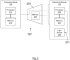
- connection point 107 comprises a connector having a connector backshell 201.
- the connector further comprises within the backshell 201 a non-volatile memory 203 (in this example, an EEPROM).
- the memory 203 comprises an identifier of the connection point 107.
- the identifier comprises a binary identification number, unique to the connection point 107.
- the memory 203 is connected, via the connector, to the electronic module 103.
- the connection point 107 is also configured to facilitate communication between the electronic module 103 and the central computing node 105.
- the electronic module 103 comprises a processor 205 and an associated memory 207.
- the processor 205 is configured to control (for example, by executing one or more instructions stored in the associated memory 207) one or more of the functions of the electronic module 103.
- the electronic module 103 comprises a lighting device.
- the electronic module 103 comprises a light source 209.
- the processor 205 is configured to generate a light source control signal 211 to control the light source.
- the processor 205 is connected to the memory 203 in the wiring harness 101 by a communication interface.
- the communication interface consists of a single wire.
- the processor 205 and the memory 203 are configured to communicate (for example, to exchange connection point identification requests and connection point identifiers) via a half-duplex communication protocol operating over the single wire.
- the processor 205 is further configured to transmit a connection point identification request.
- the processor 205 is configured to transmit the connection point identification request to the memory 203.
- the connection point identification request comprises a memory read command.
- the memory 203 is configured to respond to receipt of the connection point identification request by transmitting, to the electronic module 103 (in this case, to the processor 205) the stored identifier of the connection point 107.
- Processor 205 is further configured to receive the identifier.
- the processor 205 is further configured to, on the basis of the received identifier, determine configuration data for the electronic module 103. By determining configuration data based on the received identifier, the processor 205 can determine configuration data associated with the connection point 107 (for example, configuration data suitable for configuring the electronic module 103 to operate at a position in the aircraft electrical system 100 associated with the connection point 107). In this example embodiment, the processor 205 is configured to determine the configuration data by searching a look-up table (for example, stored in memory 207) for an entry associated with the received identifier. In this case, the entry comprises a memory address for a location in memory 207 from where the configuration data can be retrieved. The processor 205 is further configured to, on the basis of the memory address, retrieve the determined configuration data.
- a look-up table for example, stored in memory 207
- the processor 205 is further configured to configure the electronic module 103 to operate in accordance with the determined configuration data.
- the processor 205 is configured to configure the electronic module 103 to operate in a manner suitable for the connection point 107 and the position in the aircraft electrical system 100 associated with the connection point 107.
- processor 205 is configured to control light source 209 (for example by generating light source control signal 211) in accordance with the configuration data.
- the processor 205 is further configured to evaluate the received identifier to determine whether the electronic module 103 has been connected to a connection point for which it is unsuitable. For example, it may be that the electronic module 103 (which, as previously discussed comprises a lighting device) has been connected to a connection point intended for an occupancy sensor. In such cases, the processor 205 is configured to, in response to the determining, generate an alert. In this example embodiment, generating the alert comprises transmitting a signal to the computing node 105 indicating that the electronic module 103 has been connected to an incompatible connection point. It will be appreciated that, in other embodiments, the electronic module 105 may comprise a warning light or buzzer. In such cases, it may be that the alert comprises an audible alert (for example, sounding the buzzer) or a visible alert (for example, lighting the warning light).
- the computing node 105 also comprises a processor 213 and an associated memory 215.
- the processor 213 is configured to control (for example, by executing one or more instructions stored in the associated memory 215) one or more of the functions of the computing node 105.
- a second embodiment of the invention comprises an aircraft electrical system substantially as described in respect of the first embodiment, except for the following differences.
- the processor 205 is configured to retrieve the determined configuration data not from memory 207, but from the central computing node 105.
- the processor 205 is configured to transmit the identifier to the central computing node 105.
- the processor 213 of the computing node 105 is configured to determine the configuration by searching a look-up table (for example, stored in memory 215) for an entry associated with the received identifier.
- the entry comprises a memory address for a location in memory 215 from where the configuration data can be retrieved.
- the processor 213 is further configured to, on the basis of the memory address, retrieve the determined configuration data from the memory 215 and transmit the retrieved configuration data to the electronic module 103 (for example, via the wiring harness 101 and the connection point 107).
- the processor 205 of the electronic module 103 is configured to receive the transmitted configuration data and, in response to the receipt of the configuration data, configure the electronic module 103 to operate in accordance with the received configuration data.
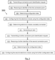
- Figure 3 shows a flow chart illustrating the steps of a method 300 of configuring an aircraft electrical system according to a third embodiment of the invention.
- the electrical system comprises a wiring harness and a plurality of electronic modules.
- a first electronic module in the plurality is connected to the wiring harness via a first connection point in the plurality.
- the first electronic module may comprise one or more of a lighting device, a sensor, a heating and/or cooling unit, a passenger control unit.
- the wiring harness comprises a plurality of connection points.
- the aircraft electrical system may comprise an aircraft cabin avionics network. In such cases, it may be that each of the plurality of connection points is associated with a different position within the aircraft cabin.
- a first step of the method 300 comprises transmitting by the first electronic module, a connection point identification request.
- connection point identification request is transmitted to a memory (for example, a memory associated with the first connection point).
- wiring harness comprises the memory.
- the first connection point may comprise a connector.
- the connector may have a connector backshell. In such cases, it may be that the memory is located within the connector backshell.
- the electrical system comprises a communication interface between the first electronic module and the memory. The transmitting of the connection point identification request may be via the communication interface. In such cases, it may be that the connection point identification request is transmitted to the computing node.
- a second step of the method 300 comprises, in response to the transmitting, receiving at the first electronic module from the wiring harness, an identifier of the first connection point.
- the identifier is received from a memory (for example, the memory within the connector backshell of the first connection point).
- the receiving of the identifier may be via the communication interface.
- a third step of the method 300 comprises, on the basis of the received identifier, determining configuration data for the first electronic module, the configuration data being associated with the first connection point.
- a fourth step, of the method 300, represented by item 307, comprises configuring the first electronic module to operate in accordance with the determined configuration data.
- the aircraft electrical system comprises an aircraft cabin avionics network and each of the plurality of connection points is associated with a different position within the aircraft cabin
- the configuring of the first electronic module comprises configuring the first electronic module to operate in accordance with the position associated with the first connection point.
- An optional fifth step of the method 300, represented by item 309, comprises, on the basis of the received identifier, determining that the first electronic module is connected to a connection point for which it is unsuitable.
- An optional sixth step of the method 300 comprises in response to determining that the first electronic module is connected to a connection point for which it is unsuitable, generating an alert.
- an optional seventh step of the method 300 comprises, in response to the connecting, transmitting by the second electronic module, a further connection point identification request.
- An optional eighth step of the method 300, represented by item 315, comprises, in response to the transmitting of the further connection point identification request, receiving at the second electronic module from the wiring harness, a further identifier of the second connection point.
- An optional ninth step of the method 300, represented by item 317, comprises, on the basis of the received further identifier, determining further configuration data for the second electronic module, the further configuration data being associated with the second connection point.
- the further configuration data differs from the configuration data. It may be that the first electronic module and the second electronic module are, prior to configuration, substantially identical. It may be that the configuration data and the further configuration data differ such that the second electronic module is configured to operate differently to the first electronic module.
- An optional tenth step of the method 300 comprises configuring the second electronic module to operate in accordance with the determined further configuration data.
- the aircraft electrical system 100 comprises three electronic modules, it will be appreciated by the skilled person that, in other embodiments, the aircraft electrical system may comprise more or fewer than three electronic modules.
- the wiring harness 101 may also provide links between one or more (for example, all) of the plurality of electronic modules 103a, 103b, 103c.
- the wiring harness 101 may connect the plurality of electronic modules 103a, 103b, 103c and the central computing node by means of a bus network topology, rather than by point-to-point links. It will be appreciated by the skilled person that the present invention can be applied to a range of network topologies and configurations.
- each of the electronic modules 103a, 103b, 103c and the computing node 105 may each comprise one or more processors and/or memory.
- each of the electronic modules 103a, 103b, 103c comprises a processor 205 and associated memory 207.
- Processor 205 and associated memory 207 may be configured to perform one or more of the above-described functions of the electronic module.
- computing node 105 comprises a processor 213 and associated memory 215.
- Processor 213 and associated memory 215 may be configured to perform one or more of the above-described functions of computing node 105.
- Each device, module, component, machine or function as described in relation to any of the examples described herein may similarly comprise a processor or may be comprised in apparatus comprising a processor.
- One or more aspects of the embodiments described herein comprise processes performed by apparatus.
- the apparatus comprises one or more processors configured to carry out these processes.
- embodiments may be implemented at least in part by computer software stored in (non-transitory) memory and executable by the processor, or by hardware, or by a combination of tangibly stored software and hardware (and tangibly stored firmware).
- Embodiments also include computer programs, particularly computer programs on or in a carrier, adapted for putting the above-described embodiments into practice.
- the program may be in the form of non-transitory source code, object code, or in any other non-transitory form suitable for use in the implementation of processes according to embodiments.
- the carrier may be any entity or device capable of carrying the program, such as a RAM, a ROM, or an optical memory device, etc.
- the one or more processors of the electronic modules 103a, 103b, 103c and the computing node 105 may comprise a central processing unit (CPU).
- the one or more processors may comprise a graphics processing unit (GPU).
- the one or more processors may comprise one or more of a field programmable gate array (FPGA), a programmable logic device (PLD), or a complex programmable logic device (CPLD).
- the one or more processors may comprise an application specific integrated circuit (ASIC). It will be appreciated by the skilled person that many other types of device, in addition to the examples provided, may be used to provide the one or more processors.
- the one or more processors may comprise multiple co-located processors or multiple disparately located processors. Operations performed by the one or more processors may be carried out by one or more of hardware, firmware, and software.
- the one or more processors may comprise data storage.
- the data storage may comprise one or both of volatile and non-volatile memory.
- the data storage may comprise one or more of random access memory (RAM), read-only memory (ROM), a magnetic or optical disk and disk drive, or a solid-state drive (SSD). It will be appreciated by the skilled person that many other types of memory, in addition to the examples provided, may also be used. It will be appreciated by a person skilled in the art that the one or more processors may each comprise more, fewer and/or different components from those described.
- the techniques described herein may be implemented in software or hardware, or may be implemented using a combination of software and hardware. They may include configuring an apparatus to carry out and/or support any or all of techniques described herein.
- examples described herein with reference to the drawings comprise computer processes performed in processing systems or processors, examples described herein also extend to computer programs, for example computer programs on or in a carrier, adapted for putting the examples into practice.
- the carrier may be any entity or device capable of carrying the program.
- the carrier may comprise a computer readable storage media.
- tangible computer-readable storage media include, but are not limited to, an optical medium (e.g., CD-ROM, DVD-ROM or Blu-ray), flash memory card, floppy or hard disk or any other medium capable of storing computer-readable instructions such as firmware or microcode in at least one ROM or RAM or Programmable ROM (PROM) chips.
- an optical medium e.g., CD-ROM, DVD-ROM or Blu-ray
- flash memory card e.g., DVD-ROM or Blu-ray
- flash memory card e.g., floppy or hard disk
- any other medium capable of storing computer-readable instructions such as firmware or microcode in at least one ROM or RAM or Programmable ROM (PROM) chips.
Landscapes
- Engineering & Computer Science (AREA)
- Physics & Mathematics (AREA)
- General Physics & Mathematics (AREA)
- Computer Networks & Wireless Communication (AREA)
- Signal Processing (AREA)
- Automation & Control Theory (AREA)
- Health & Medical Sciences (AREA)
- Medical Informatics (AREA)
- General Health & Medical Sciences (AREA)
- Computing Systems (AREA)
- Artificial Intelligence (AREA)
- Computer Vision & Pattern Recognition (AREA)
- Evolutionary Computation (AREA)
- Software Systems (AREA)
- General Engineering & Computer Science (AREA)
- Small-Scale Networks (AREA)
- Circuit Arrangement For Electric Light Sources In General (AREA)
Description
- The present invention concerns aircraft electrical systems. More particularly, but not exclusively, this invention concerns a method of configuring an aircraft electrical system. The invention is particularly suited to aircraft cabin electrical systems.
- Aircraft electrical systems often incorporate wiring harnesses, which serve to connect remote electrical subsystems. Such wiring harnesses typically have a number of connection points, to which an electronic module can be connected to provide power to and/or enable communication with the electronic module. Generally, each of the connection points of a wiring harness is associated with a particular location and/or function within the electrical system. For example, where the electrical system comprises an aircraft cabin avionics network, the connection points may be associated with light fittings or occupancy sensors positioned throughout the aircraft cabin. In such cases, the electronic module may comprise a lighting device or a sensor module. Other examples of electronic modules are heating and/or cooling units, and passenger control units. Such electronic modules for use in the aircraft cabin are sometimes known as line-replaceable units.
- It is usually the case that connection points at different locations are associated with different intended functionality; that is to say that devices at different locations within the system are intended to behave differently. For example, a lighting device connected in a first location within an aircraft cabin may be required to behave in a different manner to another lighting device connected in a second, different location within the aircraft cabin. Thus, although both connection points should be connected to a lighting device, the same lighting device itself is not necessarily suitable to operate in both locations (as it must be configured to behave in a manner appropriate for its intended location).
- Thus, there are a large number of unique electronic modules (for example, one for each required configuration of electronic module) that must be produced and managed. Even where electronic modules can share hardware (for example, in the case of lighting devices), the need for different behaviours at different locations requires multiple different software configurations, each of which must be independently certified and maintained. Furthermore, the need for large numbers of distinct parts which must be connected in specific locations increases the difficulty of installing the electrical system and therefore the chance of mistakes occurring (for example, by installing an electronic module in an inappropriate location). Thus, the requirement for a large number of unique electronic modules adds complexity to design, certification, and installation of the electrical system.
- The present invention seeks to mitigate the above-mentioned problems. Alternatively or additionally, the present invention seeks to provide an improved aircraft electrical system.
- Thanthry N et al "Aviation data networks: security issues and network architecture", 38th Annual International Conference On Security Technology, 2004 published 11 October 2004 discloses a wireless control network with connection endpoints for an aircraft.
-
US 2017/341777 A1 (Kumar, Anil et al) published 30 November 2017 discloses apparatus for managing aircraft health data including a wireless network server disposed onboard an aircraft, and at least one wireless condition monitoring device disposed onboard the aircraft, wirelessly connected to the wireless network server and configured to transmit respective health data to the wireless network server based on a communication scheme that maintains an availability of an aircraft wireless network. - The present invention provides, according to a first aspect, a method of configuring an aircraft electrical system, wherein:
- the electrical system comprises a wiring harness and a plurality of electronic modules;
- the wiring harness comprises a plurality of connection points;
- a first electronic module in the plurality is connected to the wiring harness via a first connection point in the plurality; and
- the method comprises:
- transmitting by the first electronic module, a connection point identification request;
- in response to the transmitting, receiving at the first electronic module from the wiring harness, an identifier of the first connection point;
- on the basis of the received identifier, determining configuration data for the first electronic module, the configuration data being associated with the first connection point; and
- configuring the first electronic module to operate in accordance with the determined configuration data.
- By transmitting a connection point identification request and, in response to the transmitting, receiving from the wiring harness an identifier of the connection point, the first electronic module can determine the connection point to which it has been connected. By subsequently determining configuration data for the first electronic module on the basis of the identifier (and thereby on the basis of the connection point to which the first electronic module is connected), the first electronic module can identify, and configure itself to operate in accordance with, configuration data specific to the connection point. Thus, the method of the present invention enables the use of a generic electronic module which is configured to automatically reconfigure itself to operate in a manner suitable for the connection point to which it is connected, and thereby in an appropriate manner for the location in the electrical system in which the electronic module has been installed.
- The first electronic module may be a line-replaceable unit. The first electronic module may comprise one or more of a lighting device, a sensor, a heating and/or cooling unit, a passenger control unit.
- It may be that the transmitting of the connection point identification request is performed in response to the connecting of the first electronic module. The method may further comprise detecting that the first electronic module has been connected to the first connection point. In such cases, the transmitting may be in response to the detecting. The transmitting of the connection point identification request may be in response to receipt of user input to the first electronic module (for example, a user pressing a configuration button on the first electronic module or sending a configuration command to the first electronic module via a debugging/configuration interface of the first electronic module). The transmitting of the connection point identification request may be in response to receipt of a configuration command received via the wiring harness (for example, from a computing node of the electrical system). Such a configuration command may be broadcast by another computing element connected to the wiring harness. It will be appreciated that a computing element can transmit a broadcast message without any knowledge of the recipients, and thus doing so can allow the computing element to deliver a command to an unconfigured electronic module.
- It may be that the connection point identification request is transmitted to a memory associated with the first connection point. In such cases, it may be that the identifier is received from the memory. Thus, the connection point identification request may comprise a memory access request or read command. It may be that the wiring harness comprises the memory. The first connection point may comprise a connector. The connector may have a connector backshell. In such cases, it may be that the memory is located within the connector backshell. It will be appreciated by the skilled person that the memory may alternatively be located in parts of the wiring harness other than a connector backshell. The memory may comprise a non-volatile memory. The memory may comprise one or more of an erasable programmable read-only memory (EEPROM), flash memory, and read-only memory (ROM).
- It may be that the electrical system comprises a communication interface between the first electronic module and the memory. The communication interface may be configured to facilitate the transmission of memory access requests (for example, a connection point identification request) and/or data (for example, an identifier) between the memory and the first electronic module. In such cases, it may be that the communication interface consists of a single wire. Thus, it may be that the communication interface is configured to provide half-duplex communication between the first electronic module and the memory. The transmitting of the connection point identification request and the receiving of the identifier may be via the communication interface.
- It may be that determining the configuration data comprises identifying configuration data associated with the received identifier. It may be that identifying the configuration data comprises retrieving an entry from a look-up table (for example, an entry associated with the received identifier). The electrical system may comprise a central computing node. In such cases, it may be that determining the configuration data comprises transmitting the received identifier to the central computing node. In such cases, the determining may further comprise, in response to the transmitting of the identifier, receiving from the central computing node an indication of configuration data for use in configuring the first electronic module (for example, associated with the identifier and/or the first connection point). The indication of configuration data may comprise an indication of a network location (for example, a network address) from where the configuration data can be retrieved. The indication of configuration data may comprise an indication of one of a plurality of modes of operation pre-programmed into the electronic module.
- It may be that the configuring comprises retrieving the configuration data from a memory (for example, comprised in the first electronic module). It may be that the configuring comprises retrieving the configuration data from another computing element (for example, one connected to the first electronic module via the wiring harness). It may be that a plurality of configuration states of the first electronic module are hard-coded into firmware or software running on one or more computing elements of the first electronic module. It may be that the configuring comprises causing the first electronic module (for example, the one or more computing elements of the first electronic module) to operate in a given one of the plurality of configuration states (for example, a configuration state associated with the received identifier).
- Configuring the first electronic module may comprise causing the first electronic module to associate itself with a specific network address (for example, one associated with the received identifier and/or the first connection point). Configuring the first electronic module may comprise causing the first electronic module to communicate via the wiring harness in accordance with one or more communication protocols (for example, associated with the received identifier and/or the first connection point). Configuring the first electronic module may comprise causing the first electronic module to operate in accordance with one or more operational parameters (for example, associated with the received identifier and/or the first connection point). For example, where the first electronic module comprises a lighting device, the one or more operational parameters may define one or more of: an intensity of light emission by the lighting device, a duration of light emission by the lighting device, a colour of light emission by the lighting device, and one or more trigger conditions for changes in intensity, duration, and/or colour of light emission by the lighting device. In a further example in which the first electronic module comprises a sensor, the one or more operational parameters may define one or more of a sampling frequency of the sensor, a data format for transmission of the sensor data, and one or more trigger conditions for beginning or ceasing operation of the sensor.
- The aircraft electrical system may comprise an aircraft cabin avionics network. In such cases, it may be that each of the plurality of connection points is associated with a different position within the aircraft cabin. For example, it may be that one or more connection points in the plurality are associated with lighting devices to be installed within the aircraft cabin. It may be that determining the configuration data comprises identifying configuration data suitable for a position associated with the first connection point. It may be that the configuring of the first electronic module comprises configuring the first electronic module to operate in accordance with the position associated with the first connection point.
- It will be appreciated by the skilled person that the features described above in respect of the first electronic module and the first connection point may be repeated separately in respect of one or more further electronic modules and connection points. Thus, it may be that a second electronic module in the plurality is connected to the wiring harness via a second connection point in the plurality. In such cases, the method may further comprise transmitting by the second electronic module, a further connection point identification request. The method may further comprise, in response to the transmitting of the further connection point identification request, receiving at the second electronic module from the wiring harness, a further identifier of the second connection point. The method may comprise, on the basis of the received further identifier, determining further configuration data for the second electronic module, the further configuration data being associated with the second connection point. The method may comprise configuring the second electronic module to operate in accordance with the determined further configuration data.
- It may be that the further configuration data differs from the configuration data. Thus, it may be that the configuration data and the further configuration data are such that the first and second electronic modules are configured to operate differently. It may be that the first electronic module and the second electronic module are, prior to configuration, substantially identical. It may be that, post-configuration, only software and/or firmware functionality differ between the first electronic module and the second electronic module.
- The method may further comprise, on the basis of the received identifier, determining that the electronic module is connected to a connection point for which it is unsuitable. In such cases, it may be that the method further comprises, in response to the determining, generating an alert. The alert may comprise an audible alert (for example, sounding a buzzer) or a visible alert (for example, lighting a light or display of a warning message on a display). It may be that generating the alert comprises transmitting a signal to another computing node (for example, indicating that an incompatible electronic module has been connected to a connection point).
- According to a second aspect of the invention there is provided a computer program product comprising instructions which, when executed by a computing device comprising a processor and memory, cause the computer to carry out a method of configuring an aircraft electrical system, wherein:
- the electrical system comprises a wiring harness and a plurality of electronic modules;
- the wiring harness comprises a plurality of connection points;
- a first electronic module in the plurality is connected to the wiring harness via a first connection point in the plurality; and
- the method comprises:
- transmitting by the first electronic module, a connection point identification request;
- in response to the transmitting, receiving at the first electronic module from the wiring harness, an identifier of the first connection point;
- on the basis of the received identifier, determining configuration data for the first electronic module, the configuration data being associated with the first connection point; and
- configuring the first electronic module to operate in accordance with the determined configuration data.
- According to a third aspect of the present invention there is provided an aircraft electrical system comprising:
- a wiring harness, the wiring harness comprising a plurality of connection points; and
- a plurality of electronic modules, a first electronic module in the plurality being connected to the wiring harness via a first connection point in the plurality;
- wherein the first electronic module is configured to:
- transmit, via the wiring harness, a connection point identification request;
- receive from the wiring harness an identifier of the first connection point;
- on the basis of the received identifier, determine configuration data for the first electronic module, the configuration data being associated with the first connection point; and
- configure the first electronic module to operate in accordance with the determined configuration data.
- According to a fourth aspect of the invention there is provided an aircraft comprising an aircraft electrical system as described above.
- It will of course be appreciated that features described in relation to one aspect of the present invention may be incorporated into other aspects of the present invention. For example, the method of the invention may incorporate any of the features described with reference to the apparatus of the invention and vice versa.
- Embodiments of the present invention will now be described by way of example only with reference to the accompanying schematic drawings of which:
- Figure 1
- shows a schematic view of an aircraft electrical system according to a first embodiment of the invention;
- Figure 2
- shows an expanded schematic view of the aircraft electrical system of
Figure 1 ; and - Figure 3
- shows a flow chart illustrating the steps of a method according to a third embodiment of the invention.
-
Figure 1 shows a schematic view of an aircraftelectrical system 100 according to a first embodiment of the invention. In this example, embodiment, the aircraftelectrical system 100 comprises an aircraft cabin avionics network. The aircraftelectrical system 100 comprises awiring harness 101, a plurality ofelectronic modules central computing node 105. - The
wiring harness 101 is configured to connect the plurality ofelectronic modules central computing node 105 so as to facilitate communication between theelectronic modules central computing node 105. In other embodiments, thewiring harness 101 may also enable the distribution of electrical power to one or more of the plurality ofelectronic modules central computing node 105. - In the embodiment illustrated in
Figure 1 , the wiring harness is shown as a series of direct point-to-point links between each of the plurality ofelectronic modules central computing node 105. However, in other embodiments, thewiring harness 101 may also provide links between one or more (for example, all) of the plurality ofelectronic modules wiring harness 101 may comprise a fully interconnected mesh network). Similarly, in yet other embodiments, thewiring harness 101 may link the plurality ofelectronic modules - The
wiring harness 101 comprises a plurality ofconnection points electronic modules wiring harness 101. In this example embodiments, each of the plurality of connection points is associated with a different position within the aircraft cabin. - In this example embodiment, each of the plurality of
connection points electronic modules electronic modules connection points Figure 1 showselectronic module 103a being arranged to connect toconnection point 107a,electronic module 103a may equally be connected to either of theother connection points electronic modules -
Figure 2 shows an expanded schematic view of the aircraftelectrical system 100. In this example embodiment, theconnection point 107 comprises a connector having aconnector backshell 201. The connector further comprises within the backshell 201 a non-volatile memory 203 (in this example, an EEPROM). Thememory 203 comprises an identifier of theconnection point 107. In this example embodiment, the identifier comprises a binary identification number, unique to theconnection point 107. Thememory 203 is connected, via the connector, to theelectronic module 103. Theconnection point 107 is also configured to facilitate communication between theelectronic module 103 and thecentral computing node 105. - The
electronic module 103 comprises aprocessor 205 and an associatedmemory 207. Theprocessor 205 is configured to control (for example, by executing one or more instructions stored in the associated memory 207) one or more of the functions of theelectronic module 103. In this example embodiment, theelectronic module 103 comprises a lighting device. Thus, theelectronic module 103 comprises alight source 209. In this example embodiment, theprocessor 205 is configured to generate a lightsource control signal 211 to control the light source. - The
processor 205 is connected to thememory 203 in thewiring harness 101 by a communication interface. In this example embodiment, the communication interface consists of a single wire. Thus, theprocessor 205 and thememory 203 are configured to communicate (for example, to exchange connection point identification requests and connection point identifiers) via a half-duplex communication protocol operating over the single wire. It will be appreciated by the skilled person that there may also be one or more power supply and ground wires for the purposes of powering the memory. Such wires are not considered to form part of the communication interface. - The
processor 205 is further configured to transmit a connection point identification request. In this example embodiment, theprocessor 205 is configured to transmit the connection point identification request to thememory 203. In this embodiment, the connection point identification request comprises a memory read command. Thememory 203 is configured to respond to receipt of the connection point identification request by transmitting, to the electronic module 103 (in this case, to the processor 205) the stored identifier of theconnection point 107.Processor 205 is further configured to receive the identifier. - The
processor 205 is further configured to, on the basis of the received identifier, determine configuration data for theelectronic module 103. By determining configuration data based on the received identifier, theprocessor 205 can determine configuration data associated with the connection point 107 (for example, configuration data suitable for configuring theelectronic module 103 to operate at a position in the aircraftelectrical system 100 associated with the connection point 107). In this example embodiment, theprocessor 205 is configured to determine the configuration data by searching a look-up table (for example, stored in memory 207) for an entry associated with the received identifier. In this case, the entry comprises a memory address for a location inmemory 207 from where the configuration data can be retrieved. Theprocessor 205 is further configured to, on the basis of the memory address, retrieve the determined configuration data. - The
processor 205 is further configured to configure theelectronic module 103 to operate in accordance with the determined configuration data. Thus, theprocessor 205 is configured to configure theelectronic module 103 to operate in a manner suitable for theconnection point 107 and the position in the aircraftelectrical system 100 associated with theconnection point 107. In this example embodiment,processor 205 is configured to control light source 209 (for example by generating light source control signal 211) in accordance with the configuration data. - The
processor 205 is further configured to evaluate the received identifier to determine whether theelectronic module 103 has been connected to a connection point for which it is unsuitable. For example, it may be that the electronic module 103 (which, as previously discussed comprises a lighting device) has been connected to a connection point intended for an occupancy sensor. In such cases, theprocessor 205 is configured to, in response to the determining, generate an alert. In this example embodiment, generating the alert comprises transmitting a signal to thecomputing node 105 indicating that theelectronic module 103 has been connected to an incompatible connection point. It will be appreciated that, in other embodiments, theelectronic module 105 may comprise a warning light or buzzer. In such cases, it may be that the alert comprises an audible alert (for example, sounding the buzzer) or a visible alert (for example, lighting the warning light). - The
computing node 105 also comprises aprocessor 213 and an associatedmemory 215. Theprocessor 213 is configured to control (for example, by executing one or more instructions stored in the associated memory 215) one or more of the functions of thecomputing node 105. - A second embodiment of the invention comprises an aircraft electrical system substantially as described in respect of the first embodiment, except for the following differences. The
processor 205 is configured to retrieve the determined configuration data not frommemory 207, but from thecentral computing node 105. Thus, theprocessor 205 is configured to transmit the identifier to thecentral computing node 105. In this example embodiment, theprocessor 213 of thecomputing node 105 is configured to determine the configuration by searching a look-up table (for example, stored in memory 215) for an entry associated with the received identifier. In this case, the entry comprises a memory address for a location inmemory 215 from where the configuration data can be retrieved. Theprocessor 213 is further configured to, on the basis of the memory address, retrieve the determined configuration data from thememory 215 and transmit the retrieved configuration data to the electronic module 103 (for example, via thewiring harness 101 and the connection point 107). Theprocessor 205 of theelectronic module 103 is configured to receive the transmitted configuration data and, in response to the receipt of the configuration data, configure theelectronic module 103 to operate in accordance with the received configuration data. -
Figure 3 shows a flow chart illustrating the steps of amethod 300 of configuring an aircraft electrical system according to a third embodiment of the invention. - The electrical system comprises a wiring harness and a plurality of electronic modules. A first electronic module in the plurality is connected to the wiring harness via a first connection point in the plurality. The first electronic module may comprise one or more of a lighting device, a sensor, a heating and/or cooling unit, a passenger control unit. The wiring harness comprises a plurality of connection points. The aircraft electrical system may comprise an aircraft cabin avionics network. In such cases, it may be that each of the plurality of connection points is associated with a different position within the aircraft cabin.
- A first step of the
method 300, represented byitem 301, comprises transmitting by the first electronic module, a connection point identification request. - It may be that the connection point identification request is transmitted to a memory (for example, a memory associated with the first connection point). It may be that wiring harness comprises the memory. The first connection point may comprise a connector. The connector may have a connector backshell. In such cases, it may be that the memory is located within the connector backshell. It may be that the electrical system comprises a communication interface between the first electronic module and the memory. The transmitting of the connection point identification request may be via the communication interface. In such cases, it may be that the connection point identification request is transmitted to the computing node.
- A second step of the
method 300, represented byitem 303, comprises, in response to the transmitting, receiving at the first electronic module from the wiring harness, an identifier of the first connection point. - It may be that the identifier is received from a memory (for example, the memory within the connector backshell of the first connection point). The receiving of the identifier may be via the communication interface.
- A third step of the
method 300, represented by item 305, comprises, on the basis of the received identifier, determining configuration data for the first electronic module, the configuration data being associated with the first connection point. - A fourth step, of the
method 300, represented by item 307, comprises configuring the first electronic module to operate in accordance with the determined configuration data. - Where the aircraft electrical system comprises an aircraft cabin avionics network and each of the plurality of connection points is associated with a different position within the aircraft cabin, it may be that the configuring of the first electronic module comprises configuring the first electronic module to operate in accordance with the position associated with the first connection point.
- An optional fifth step of the
method 300, represented byitem 309, comprises, on the basis of the received identifier, determining that the first electronic module is connected to a connection point for which it is unsuitable. - An optional sixth step of the
method 300, represented byitem 311, comprises in response to determining that the first electronic module is connected to a connection point for which it is unsuitable, generating an alert. - It may be that a second electronic module in the plurality is connected to the wiring harness via a second connection point in the plurality. In such cases, an optional seventh step of the
method 300, represented byitem 313, comprises, in response to the connecting, transmitting by the second electronic module, a further connection point identification request. - An optional eighth step of the
method 300, represented byitem 315, comprises, in response to the transmitting of the further connection point identification request, receiving at the second electronic module from the wiring harness, a further identifier of the second connection point. - An optional ninth step of the
method 300, represented by item 317, comprises, on the basis of the received further identifier, determining further configuration data for the second electronic module, the further configuration data being associated with the second connection point. - It may be that the further configuration data differs from the configuration data. It may be that the first electronic module and the second electronic module are, prior to configuration, substantially identical. It may be that the configuration data and the further configuration data differ such that the second electronic module is configured to operate differently to the first electronic module.
- An optional tenth step of the
method 300, represented by item 321, comprises configuring the second electronic module to operate in accordance with the determined further configuration data. - Whilst the present invention has been described and illustrated with reference to particular embodiments, it will be appreciated by those of ordinary skill in the art that the invention lends itself to many different variations not specifically illustrated herein. By way of example only, certain possible variations will now be described.
- Whilst in the embodiment illustrated in
Figure 1 the aircraftelectrical system 100 comprises three electronic modules, it will be appreciated by the skilled person that, in other embodiments, the aircraft electrical system may comprise more or fewer than three electronic modules. - Whilst the illustrated embodiments show the wiring harness as a series of direct point-to-point links between each of the plurality of
electronic modules central computing node 105, in other embodiments thewiring harness 101 may also provide links between one or more (for example, all) of the plurality ofelectronic modules wiring harness 101 may connect the plurality ofelectronic modules - It will be appreciated that the
electronic modules computing node 105 may each comprise one or more processors and/or memory. Thus, in embodiments, each of theelectronic modules processor 205 and associatedmemory 207.Processor 205 and associatedmemory 207 may be configured to perform one or more of the above-described functions of the electronic module. Similarly, in embodiments,computing node 105 comprises aprocessor 213 and associatedmemory 215.Processor 213 and associatedmemory 215 may be configured to perform one or more of the above-described functions ofcomputing node 105. Each device, module, component, machine or function as described in relation to any of the examples described herein (for example, theelectronic modules computing node 105, thememory 203, and the light source 209) may similarly comprise a processor or may be comprised in apparatus comprising a processor. One or more aspects of the embodiments described herein comprise processes performed by apparatus. In some examples, the apparatus comprises one or more processors configured to carry out these processes. In this regard, embodiments may be implemented at least in part by computer software stored in (non-transitory) memory and executable by the processor, or by hardware, or by a combination of tangibly stored software and hardware (and tangibly stored firmware). Embodiments also include computer programs, particularly computer programs on or in a carrier, adapted for putting the above-described embodiments into practice. The program may be in the form of non-transitory source code, object code, or in any other non-transitory form suitable for use in the implementation of processes according to embodiments. The carrier may be any entity or device capable of carrying the program, such as a RAM, a ROM, or an optical memory device, etc. - The one or more processors of the
electronic modules computing node 105 may comprise a central processing unit (CPU). The one or more processors may comprise a graphics processing unit (GPU). The one or more processors may comprise one or more of a field programmable gate array (FPGA), a programmable logic device (PLD), or a complex programmable logic device (CPLD). The one or more processors may comprise an application specific integrated circuit (ASIC). It will be appreciated by the skilled person that many other types of device, in addition to the examples provided, may be used to provide the one or more processors. The one or more processors may comprise multiple co-located processors or multiple disparately located processors. Operations performed by the one or more processors may be carried out by one or more of hardware, firmware, and software. - The one or more processors may comprise data storage. The data storage may comprise one or both of volatile and non-volatile memory. The data storage may comprise one or more of random access memory (RAM), read-only memory (ROM), a magnetic or optical disk and disk drive, or a solid-state drive (SSD). It will be appreciated by the skilled person that many other types of memory, in addition to the examples provided, may also be used. It will be appreciated by a person skilled in the art that the one or more processors may each comprise more, fewer and/or different components from those described.
- The techniques described herein may be implemented in software or hardware, or may be implemented using a combination of software and hardware. They may include configuring an apparatus to carry out and/or support any or all of techniques described herein. Although at least some aspects of the examples described herein with reference to the drawings comprise computer processes performed in processing systems or processors, examples described herein also extend to computer programs, for example computer programs on or in a carrier, adapted for putting the examples into practice. The carrier may be any entity or device capable of carrying the program. The carrier may comprise a computer readable storage media. Examples of tangible computer-readable storage media include, but are not limited to, an optical medium (e.g., CD-ROM, DVD-ROM or Blu-ray), flash memory card, floppy or hard disk or any other medium capable of storing computer-readable instructions such as firmware or microcode in at least one ROM or RAM or Programmable ROM (PROM) chips.
- Where in the foregoing description, integers or elements are mentioned which have known, obvious or foreseeable equivalents, then such equivalents are herein incorporated as if individually set forth. Reference should be made to the claims for determining the scope of the present invention.
- It will also be appreciated by the reader that integers or features of the invention that are described as preferable, advantageous, convenient or the like are optional and do not limit the scope of the independent claims. Moreover, it is to be understood that such optional integers or features, whilst of possible benefit in some embodiments of the invention, may not be desirable, and may therefore be absent, in other embodiments.
Claims (14)
- A method of configuring an aircraft electrical system (100), wherein:the electrical system (100) comprises a wiring harness (101) and a plurality of electronic modules (103a, 103b, 103c);the wiring harness (101) comprises a plurality of connection points (107a, 107b, 107c);a first electronic module (103a) in the plurality is connected to the wiring harness (101) via a first connection point (107a) in the plurality; andthe method comprises:transmitting by the first electronic module (103a), a connection point identification request;in response to the transmitting, receiving at the first electronic module (103a) from the wiring harness (101), an identifier of the first connection point (107a);on the basis of the received identifier, determining configuration data for the first electronic module (103a), the configuration data being associated with the first connection point (107a); andconfiguring the first electronic module (103a) to operate in accordance with the determined configuration data.
- A method according to claim 1, wherein:the connection point identification request is transmitted to a memory (203) associated with the first connection point (107a); andthe identifier is received from the memory (203).
- A method according to claim 2, wherein the wiring harness (101) comprises the memory (203).
- A method according to claim 3, wherein:the first connection point comprises a connector having a connector backshell (201); andthe memory (203) is located within the connector backshell (201).
- A method according to any of claims 2 to 4, wherein a communication interface between the first electronic module (103a) and the memory (203) consists of a single wire; and
the transmitting of the connection point identification request and the receiving of the identifier are via the communication interface. - A method according to any preceding claim, wherein:the aircraft electrical system (100) comprises an aircraft cabin avionics network;each of the plurality of connection points (107a, 107b, 107c) is associated with a different position within the aircraft cabin; andthe configuring comprises configuring the first electronic module (103a) to operate in accordance with the position associated with the first connection point (107a).
- A method according to any preceding claim, wherein:a second electronic module (103b) in the plurality is connected to the wiring harness (101) via a second connection point (107b) in the plurality; andthe method further comprises:transmitting by the second electronic module (103b), a further connection point identification request;in response to the transmitting, receiving at the second electronic module (103b) from the wiring harness (101), a further identifier of the second connection point (107b);on the basis of the received further identifier, determining further configuration data for the second electronic module (103b), the further configuration data being associated with the second connection point (107b); andconfiguring the second electronic module (103b) to operate in accordance with the determined further configuration data.
- A method according to claim 7, wherein the further configuration data differs from the configuration data.
- A method according to claim 7 or 8, wherein the first electronic module (103a) and the second electronic module (103a) are, prior to configuration, substantially identical.
- A method according to any preceding claim, wherein the method further comprises:on the basis of the received identifier, determining that the first electronic module (103a) is connected to a connection point (107a) for which it is unsuitable; andin response to the determining, generating an alert.
- A method according to any preceding claim, wherein the first electronic module (103a) comprises one or more of: a lighting device, a sensor, a heating and/or cooling unit, a passenger control unit.
- A computer program product comprising instructions which, when executed by a computing device comprising a processor (213) and memory (215), cause the computer to carry out a method of configuring an aircraft electrical system (100), wherein:the electrical system (100) comprises a wiring harness (101) and a plurality of electronic modules (103a, 103b, 103c);the wiring harness (101) comprises a plurality of connection points (107a, 107b, 107c);a first electronic module (103a) in the plurality is connected to the wiring harness (101) via a first connection point (107a) in the plurality; andthe method comprises:transmitting by the first electronic module (103a), a connection point identification request;in response to the transmitting, receiving at the first electronic module (103a) from the wiring harness (101), an identifier of the first connection point (107a);on the basis of the received identifier, determining configuration data for the first electronic module (103a), the configuration data being associated with the first connection point (107a); andconfiguring the first electronic module (103a) to operate in accordance with the determined configuration data.
- An aircraft electrical system (100) comprising:a wiring harness (101), the wiring harness (101) comprising a plurality of connection points (107a, 107, 107c); anda plurality of electronic modules (103a, 103b, 103c), a first electronic module (103a) in the plurality being connected to the wiring harness (101) via a first connection point (107a) in the plurality;wherein the first electronic module (103a) is configured to:transmit, via the wiring harness (101), a connection point identification request;receive from the wiring harness (101) an identifier of the first connection point (107a);on the basis of the received identifier, determine configuration data for the first electronic module (103a), the configuration data being associated with the first connection point (107a); andconfigure the first electronic module (103a) to operate in accordance with the determined configuration data.
- An aircraft comprising an aircraft electrical system (100) as claimed in claim 13.
Applications Claiming Priority (1)
| Application Number | Priority Date | Filing Date | Title |
|---|---|---|---|
| GB2116225.0A GB2612799A (en) | 2021-11-11 | 2021-11-11 | Aircraft electrical system |
Publications (2)
| Publication Number | Publication Date |
|---|---|
| EP4181482A1 EP4181482A1 (en) | 2023-05-17 |
| EP4181482B1 true EP4181482B1 (en) | 2024-07-24 |
Family
ID=79163709
Family Applications (1)
| Application Number | Title | Priority Date | Filing Date |
|---|---|---|---|
| EP22205753.1A Active EP4181482B1 (en) | 2021-11-11 | 2022-11-07 | Configuring an aircraft electrical system |
Country Status (3)
| Country | Link |
|---|---|
| US (1) | US12230422B2 (en) |
| EP (1) | EP4181482B1 (en) |
| GB (1) | GB2612799A (en) |
Family Cites Families (7)
| Publication number | Priority date | Publication date | Assignee | Title |
|---|---|---|---|---|
| DE102005034944B3 (en) * | 2005-07-22 | 2006-11-09 | Siemens Ag | Field bus system e.g. LIN bus system, configuration method for use in e.g. motor vehicle, involves checking whether bus subscriber still has standard address, and identifying subscriber and assigning clear subscriber address to subscriber |
| US9645617B2 (en) * | 2013-11-06 | 2017-05-09 | Northrop Grumman Systems Corporation | Compact memory device |
| US9990311B2 (en) * | 2015-12-28 | 2018-06-05 | Andes Technology Corporation | Peripheral interface circuit |
| US9926086B2 (en) * | 2016-05-26 | 2018-03-27 | The Boeing Company | Apparatus and method for wirelessly managing aircraft health data |
| CN110325929B (en) * | 2016-12-07 | 2021-05-25 | 阿瑞路资讯安全科技股份有限公司 | System and method for signal waveform analysis for detecting changes in wired network |
| US10822107B1 (en) * | 2019-04-19 | 2020-11-03 | The Boeing Company | Integration of vehicle management system and power distribution control |
| US20210394921A1 (en) * | 2020-06-19 | 2021-12-23 | Midwest Panel Builders LLC | Modular avionics system |
-
2021
- 2021-11-11 GB GB2116225.0A patent/GB2612799A/en active Pending
-
2022
- 2022-11-07 EP EP22205753.1A patent/EP4181482B1/en active Active
- 2022-11-08 US US17/983,172 patent/US12230422B2/en active Active
Also Published As
| Publication number | Publication date |
|---|---|
| US12230422B2 (en) | 2025-02-18 |
| GB2612799A (en) | 2023-05-17 |
| EP4181482A1 (en) | 2023-05-17 |
| GB202116225D0 (en) | 2021-12-29 |
| US20230144149A1 (en) | 2023-05-11 |
Similar Documents
| Publication | Publication Date | Title |
|---|---|---|
| US10895871B2 (en) | Method and system for automatically generating interactive wiring diagram in an industrial automation environment | |
| US11713007B2 (en) | Configurable management system for a vehicle and method of use | |
| CN105591853B (en) | L IN communication flexible scheduling method and device | |
| US8397053B2 (en) | Multi-motherboard server system | |
| CN110442073B (en) | Logical judgment method for redundant airplane management computer MIO board channel fault | |
| US10797947B2 (en) | Initialization and configuration of end point devices using a mobile device | |
| US11288054B2 (en) | Vehicular communication system | |
| US9779037B2 (en) | Establishing connectivity of modular nodes in a pre-boot environment | |
| US12333889B2 (en) | Food preparation apparatus having a virtual data bus | |
| CN105228107A (en) | A kind of vehicle abnormality processing method and relevant device | |
| EP1925120B1 (en) | A system for monitoring cable interface connections in a network | |
| CN102986151B (en) | Surveillance and data transmission device and method | |
| EP4181482A1 (en) | Aircraft electrical system | |
| CN107168725A (en) | A kind of method for upgrading software of controller, apparatus and system | |
| CN116319307B (en) | Management method of server and related device | |
| CN113965494A (en) | Method for fault detection and role selection in a redundant process network | |
| US20190279484A1 (en) | Visible indication of a port as configured to management functionality | |
| CN107708088A (en) | Data transmission method and wireless communication system | |
| EP3920545B1 (en) | Wireless communication for industrial automation | |
| EP3441955B1 (en) | System and method for downloading configuration data to fire alarm control panel devices and peripheral devices in a fire alarm system | |
| EP3720158A1 (en) | Wireless communication apparatus for performing process control in factory, and method of process control | |
| US20230052810A1 (en) | Control apparatus, control system, and method for determining function or operation of control apparatus | |
| JP7187687B2 (en) | hazard detector socket | |
| US20200137533A1 (en) | Bridge device for wireless sensors | |
| CN108810959B (en) | Communication protection method and device |
Legal Events
| Date | Code | Title | Description |
|---|---|---|---|
| PUAI | Public reference made under article 153(3) epc to a published international application that has entered the european phase |
Free format text: ORIGINAL CODE: 0009012 |
|
| STAA | Information on the status of an ep patent application or granted ep patent |
Free format text: STATUS: THE APPLICATION HAS BEEN PUBLISHED |
|
| AK | Designated contracting states |
Kind code of ref document: A1 Designated state(s): AL AT BE BG CH CY CZ DE DK EE ES FI FR GB GR HR HU IE IS IT LI LT LU LV MC ME MK MT NL NO PL PT RO RS SE SI SK SM TR |
|
| STAA | Information on the status of an ep patent application or granted ep patent |
Free format text: STATUS: REQUEST FOR EXAMINATION WAS MADE |
|
| 17P | Request for examination filed |
Effective date: 20230720 |
|
| RBV | Designated contracting states (corrected) |
Designated state(s): AL AT BE BG CH CY CZ DE DK EE ES FI FR GB GR HR HU IE IS IT LI LT LU LV MC ME MK MT NL NO PL PT RO RS SE SI SK SM TR |
|
| REG | Reference to a national code |
Ref country code: DE Free format text: PREVIOUS MAIN CLASS: H04L0067000000 Ref country code: DE Ref legal event code: R079 Ref document number: 602022004802 Country of ref document: DE Free format text: PREVIOUS MAIN CLASS: H04L0067000000 Ipc: H04L0067125000 |
|
| GRAP | Despatch of communication of intention to grant a patent |
Free format text: ORIGINAL CODE: EPIDOSNIGR1 |
|
| STAA | Information on the status of an ep patent application or granted ep patent |
Free format text: STATUS: GRANT OF PATENT IS INTENDED |
|
| RIC1 | Information provided on ipc code assigned before grant |
Ipc: H04L 67/125 20220101AFI20240221BHEP |
|
| INTG | Intention to grant announced |
Effective date: 20240306 |
|
| GRAS | Grant fee paid |
Free format text: ORIGINAL CODE: EPIDOSNIGR3 |
|
| GRAA | (expected) grant |
Free format text: ORIGINAL CODE: 0009210 |
|
| STAA | Information on the status of an ep patent application or granted ep patent |
Free format text: STATUS: THE PATENT HAS BEEN GRANTED |
|
| AK | Designated contracting states |
Kind code of ref document: B1 Designated state(s): AL AT BE BG CH CY CZ DE DK EE ES FI FR GB GR HR HU IE IS IT LI LT LU LV MC ME MK MT NL NO PL PT RO RS SE SI SK SM TR |
|
| REG | Reference to a national code |
Ref country code: GB Ref legal event code: FG4D |
|
| REG | Reference to a national code |
Ref country code: CH Ref legal event code: EP |
|
| REG | Reference to a national code |
Ref country code: IE Ref legal event code: FG4D Ref country code: DE Ref legal event code: R096 Ref document number: 602022004802 Country of ref document: DE |
|
| REG | Reference to a national code |
Ref country code: LT Ref legal event code: MG9D |
|
| REG | Reference to a national code |
Ref country code: NL Ref legal event code: MP Effective date: 20240724 |
|
| PG25 | Lapsed in a contracting state [announced via postgrant information from national office to epo] |
Ref country code: PT Free format text: LAPSE BECAUSE OF FAILURE TO SUBMIT A TRANSLATION OF THE DESCRIPTION OR TO PAY THE FEE WITHIN THE PRESCRIBED TIME-LIMIT Effective date: 20241125 |
|
| REG | Reference to a national code |
Ref country code: AT Ref legal event code: MK05 Ref document number: 1707345 Country of ref document: AT Kind code of ref document: T Effective date: 20240724 |
|
| PG25 | Lapsed in a contracting state [announced via postgrant information from national office to epo] |
Ref country code: NL Free format text: LAPSE BECAUSE OF FAILURE TO SUBMIT A TRANSLATION OF THE DESCRIPTION OR TO PAY THE FEE WITHIN THE PRESCRIBED TIME-LIMIT Effective date: 20240724 |
|
| PG25 | Lapsed in a contracting state [announced via postgrant information from national office to epo] |
Ref country code: PT Free format text: LAPSE BECAUSE OF FAILURE TO SUBMIT A TRANSLATION OF THE DESCRIPTION OR TO PAY THE FEE WITHIN THE PRESCRIBED TIME-LIMIT Effective date: 20241125 Ref country code: NL Free format text: LAPSE BECAUSE OF FAILURE TO SUBMIT A TRANSLATION OF THE DESCRIPTION OR TO PAY THE FEE WITHIN THE PRESCRIBED TIME-LIMIT Effective date: 20240724 |
|
| PG25 | Lapsed in a contracting state [announced via postgrant information from national office to epo] |
Ref country code: NO Free format text: LAPSE BECAUSE OF FAILURE TO SUBMIT A TRANSLATION OF THE DESCRIPTION OR TO PAY THE FEE WITHIN THE PRESCRIBED TIME-LIMIT Effective date: 20241024 |
|
| PG25 | Lapsed in a contracting state [announced via postgrant information from national office to epo] |
Ref country code: FI Free format text: LAPSE BECAUSE OF FAILURE TO SUBMIT A TRANSLATION OF THE DESCRIPTION OR TO PAY THE FEE WITHIN THE PRESCRIBED TIME-LIMIT Effective date: 20240724 Ref country code: PL Free format text: LAPSE BECAUSE OF FAILURE TO SUBMIT A TRANSLATION OF THE DESCRIPTION OR TO PAY THE FEE WITHIN THE PRESCRIBED TIME-LIMIT Effective date: 20240724 Ref country code: GR Free format text: LAPSE BECAUSE OF FAILURE TO SUBMIT A TRANSLATION OF THE DESCRIPTION OR TO PAY THE FEE WITHIN THE PRESCRIBED TIME-LIMIT Effective date: 20241025 |
|
| PG25 | Lapsed in a contracting state [announced via postgrant information from national office to epo] |
Ref country code: BG Free format text: LAPSE BECAUSE OF FAILURE TO SUBMIT A TRANSLATION OF THE DESCRIPTION OR TO PAY THE FEE WITHIN THE PRESCRIBED TIME-LIMIT Effective date: 20240724 |
|
| PG25 | Lapsed in a contracting state [announced via postgrant information from national office to epo] |
Ref country code: LV Free format text: LAPSE BECAUSE OF FAILURE TO SUBMIT A TRANSLATION OF THE DESCRIPTION OR TO PAY THE FEE WITHIN THE PRESCRIBED TIME-LIMIT Effective date: 20240724 |
|
| PG25 | Lapsed in a contracting state [announced via postgrant information from national office to epo] |
Ref country code: IS Free format text: LAPSE BECAUSE OF FAILURE TO SUBMIT A TRANSLATION OF THE DESCRIPTION OR TO PAY THE FEE WITHIN THE PRESCRIBED TIME-LIMIT Effective date: 20241124 Ref country code: AT Free format text: LAPSE BECAUSE OF FAILURE TO SUBMIT A TRANSLATION OF THE DESCRIPTION OR TO PAY THE FEE WITHIN THE PRESCRIBED TIME-LIMIT Effective date: 20240724 |
|
| PG25 | Lapsed in a contracting state [announced via postgrant information from national office to epo] |
Ref country code: HR Free format text: LAPSE BECAUSE OF FAILURE TO SUBMIT A TRANSLATION OF THE DESCRIPTION OR TO PAY THE FEE WITHIN THE PRESCRIBED TIME-LIMIT Effective date: 20240724 |
|
| PG25 | Lapsed in a contracting state [announced via postgrant information from national office to epo] |
Ref country code: RS Free format text: LAPSE BECAUSE OF FAILURE TO SUBMIT A TRANSLATION OF THE DESCRIPTION OR TO PAY THE FEE WITHIN THE PRESCRIBED TIME-LIMIT Effective date: 20241024 Ref country code: ES Free format text: LAPSE BECAUSE OF FAILURE TO SUBMIT A TRANSLATION OF THE DESCRIPTION OR TO PAY THE FEE WITHIN THE PRESCRIBED TIME-LIMIT Effective date: 20240724 |
|
| PG25 | Lapsed in a contracting state [announced via postgrant information from national office to epo] |
Ref country code: RS Free format text: LAPSE BECAUSE OF FAILURE TO SUBMIT A TRANSLATION OF THE DESCRIPTION OR TO PAY THE FEE WITHIN THE PRESCRIBED TIME-LIMIT Effective date: 20241024 Ref country code: PL Free format text: LAPSE BECAUSE OF FAILURE TO SUBMIT A TRANSLATION OF THE DESCRIPTION OR TO PAY THE FEE WITHIN THE PRESCRIBED TIME-LIMIT Effective date: 20240724 Ref country code: NO Free format text: LAPSE BECAUSE OF FAILURE TO SUBMIT A TRANSLATION OF THE DESCRIPTION OR TO PAY THE FEE WITHIN THE PRESCRIBED TIME-LIMIT Effective date: 20241024 Ref country code: LV Free format text: LAPSE BECAUSE OF FAILURE TO SUBMIT A TRANSLATION OF THE DESCRIPTION OR TO PAY THE FEE WITHIN THE PRESCRIBED TIME-LIMIT Effective date: 20240724 Ref country code: IS Free format text: LAPSE BECAUSE OF FAILURE TO SUBMIT A TRANSLATION OF THE DESCRIPTION OR TO PAY THE FEE WITHIN THE PRESCRIBED TIME-LIMIT Effective date: 20241124 Ref country code: HR Free format text: LAPSE BECAUSE OF FAILURE TO SUBMIT A TRANSLATION OF THE DESCRIPTION OR TO PAY THE FEE WITHIN THE PRESCRIBED TIME-LIMIT Effective date: 20240724 Ref country code: GR Free format text: LAPSE BECAUSE OF FAILURE TO SUBMIT A TRANSLATION OF THE DESCRIPTION OR TO PAY THE FEE WITHIN THE PRESCRIBED TIME-LIMIT Effective date: 20241025 Ref country code: FI Free format text: LAPSE BECAUSE OF FAILURE TO SUBMIT A TRANSLATION OF THE DESCRIPTION OR TO PAY THE FEE WITHIN THE PRESCRIBED TIME-LIMIT Effective date: 20240724 Ref country code: ES Free format text: LAPSE BECAUSE OF FAILURE TO SUBMIT A TRANSLATION OF THE DESCRIPTION OR TO PAY THE FEE WITHIN THE PRESCRIBED TIME-LIMIT Effective date: 20240724 Ref country code: BG Free format text: LAPSE BECAUSE OF FAILURE TO SUBMIT A TRANSLATION OF THE DESCRIPTION OR TO PAY THE FEE WITHIN THE PRESCRIBED TIME-LIMIT Effective date: 20240724 Ref country code: AT Free format text: LAPSE BECAUSE OF FAILURE TO SUBMIT A TRANSLATION OF THE DESCRIPTION OR TO PAY THE FEE WITHIN THE PRESCRIBED TIME-LIMIT Effective date: 20240724 |
|
| PG25 | Lapsed in a contracting state [announced via postgrant information from national office to epo] |
Ref country code: DK Free format text: LAPSE BECAUSE OF FAILURE TO SUBMIT A TRANSLATION OF THE DESCRIPTION OR TO PAY THE FEE WITHIN THE PRESCRIBED TIME-LIMIT Effective date: 20240724 Ref country code: SM Free format text: LAPSE BECAUSE OF FAILURE TO SUBMIT A TRANSLATION OF THE DESCRIPTION OR TO PAY THE FEE WITHIN THE PRESCRIBED TIME-LIMIT Effective date: 20240724 Ref country code: RO Free format text: LAPSE BECAUSE OF FAILURE TO SUBMIT A TRANSLATION OF THE DESCRIPTION OR TO PAY THE FEE WITHIN THE PRESCRIBED TIME-LIMIT Effective date: 20240724 |
|
| PG25 | Lapsed in a contracting state [announced via postgrant information from national office to epo] |
Ref country code: EE Free format text: LAPSE BECAUSE OF FAILURE TO SUBMIT A TRANSLATION OF THE DESCRIPTION OR TO PAY THE FEE WITHIN THE PRESCRIBED TIME-LIMIT Effective date: 20240724 |
|
| PG25 | Lapsed in a contracting state [announced via postgrant information from national office to epo] |
Ref country code: CZ Free format text: LAPSE BECAUSE OF FAILURE TO SUBMIT A TRANSLATION OF THE DESCRIPTION OR TO PAY THE FEE WITHIN THE PRESCRIBED TIME-LIMIT Effective date: 20240724 |
|
| REG | Reference to a national code |
Ref country code: DE Ref legal event code: R097 Ref document number: 602022004802 Country of ref document: DE |
|
| PG25 | Lapsed in a contracting state [announced via postgrant information from national office to epo] |
Ref country code: SK Free format text: LAPSE BECAUSE OF FAILURE TO SUBMIT A TRANSLATION OF THE DESCRIPTION OR TO PAY THE FEE WITHIN THE PRESCRIBED TIME-LIMIT Effective date: 20240724 Ref country code: IT Free format text: LAPSE BECAUSE OF FAILURE TO SUBMIT A TRANSLATION OF THE DESCRIPTION OR TO PAY THE FEE WITHIN THE PRESCRIBED TIME-LIMIT Effective date: 20240724 |
|
| PLBE | No opposition filed within time limit |
Free format text: ORIGINAL CODE: 0009261 |
|
| STAA | Information on the status of an ep patent application or granted ep patent |
Free format text: STATUS: NO OPPOSITION FILED WITHIN TIME LIMIT |
|
| 26N | No opposition filed |
Effective date: 20250425 |
|
| PG25 | Lapsed in a contracting state [announced via postgrant information from national office to epo] |
Ref country code: MC Free format text: LAPSE BECAUSE OF FAILURE TO SUBMIT A TRANSLATION OF THE DESCRIPTION OR TO PAY THE FEE WITHIN THE PRESCRIBED TIME-LIMIT Effective date: 20240724 |
|
| PG25 | Lapsed in a contracting state [announced via postgrant information from national office to epo] |
Ref country code: LU Free format text: LAPSE BECAUSE OF NON-PAYMENT OF DUE FEES Effective date: 20241107 |
|
| REG | Reference to a national code |
Ref country code: BE Ref legal event code: MM Effective date: 20241130 |
|
| PG25 | Lapsed in a contracting state [announced via postgrant information from national office to epo] |
Ref country code: SE Free format text: LAPSE BECAUSE OF FAILURE TO SUBMIT A TRANSLATION OF THE DESCRIPTION OR TO PAY THE FEE WITHIN THE PRESCRIBED TIME-LIMIT Effective date: 20240724 |
|
| PG25 | Lapsed in a contracting state [announced via postgrant information from national office to epo] |
Ref country code: BE Free format text: LAPSE BECAUSE OF NON-PAYMENT OF DUE FEES Effective date: 20241130 |
|
| PG25 | Lapsed in a contracting state [announced via postgrant information from national office to epo] |
Ref country code: IE Free format text: LAPSE BECAUSE OF NON-PAYMENT OF DUE FEES Effective date: 20241107 |
|
| PGFP | Annual fee paid to national office [announced via postgrant information from national office to epo] |
Ref country code: DE Payment date: 20251118 Year of fee payment: 4 |
|
| PGFP | Annual fee paid to national office [announced via postgrant information from national office to epo] |
Ref country code: FR Payment date: 20251125 Year of fee payment: 4 |
|
| PG25 | Lapsed in a contracting state [announced via postgrant information from national office to epo] |
Ref country code: HU Free format text: LAPSE BECAUSE OF FAILURE TO SUBMIT A TRANSLATION OF THE DESCRIPTION OR TO PAY THE FEE WITHIN THE PRESCRIBED TIME-LIMIT; INVALID AB INITIO Effective date: 20221107 |
|
| PG25 | Lapsed in a contracting state [announced via postgrant information from national office to epo] |
Ref country code: CY Free format text: LAPSE BECAUSE OF FAILURE TO SUBMIT A TRANSLATION OF THE DESCRIPTION OR TO PAY THE FEE WITHIN THE PRESCRIBED TIME-LIMIT; INVALID AB INITIO Effective date: 20221107 |