EP4181449B1 - Radio frequency (rf) communication system providing channel selection based upon historical rf spectral data and related methods - Google Patents
Radio frequency (rf) communication system providing channel selection based upon historical rf spectral data and related methods Download PDFInfo
- Publication number
- EP4181449B1 EP4181449B1 EP22206673.0A EP22206673A EP4181449B1 EP 4181449 B1 EP4181449 B1 EP 4181449B1 EP 22206673 A EP22206673 A EP 22206673A EP 4181449 B1 EP4181449 B1 EP 4181449B1
- Authority
- EP
- European Patent Office
- Prior art keywords
- channel
- historical
- spectral data
- radio
- communication system
- Prior art date
- Legal status (The legal status is an assumption and is not a legal conclusion. Google has not performed a legal analysis and makes no representation as to the accuracy of the status listed.)
- Active
Links
Images


Classifications
-
- H—ELECTRICITY
- H04—ELECTRIC COMMUNICATION TECHNIQUE
- H04L—TRANSMISSION OF DIGITAL INFORMATION, e.g. TELEGRAPHIC COMMUNICATION
- H04L5/00—Arrangements affording multiple use of the transmission path
- H04L5/003—Arrangements for allocating sub-channels of the transmission path
- H04L5/0058—Allocation criteria
- H04L5/006—Quality of the received signal, e.g. BER, SNR, water filling
-
- H—ELECTRICITY
- H04—ELECTRIC COMMUNICATION TECHNIQUE
- H04L—TRANSMISSION OF DIGITAL INFORMATION, e.g. TELEGRAPHIC COMMUNICATION
- H04L5/00—Arrangements affording multiple use of the transmission path
- H04L5/003—Arrangements for allocating sub-channels of the transmission path
- H04L5/0058—Allocation criteria
- H04L5/0062—Avoidance of ingress interference, e.g. ham radio channels
-
- H—ELECTRICITY
- H04—ELECTRIC COMMUNICATION TECHNIQUE
- H04L—TRANSMISSION OF DIGITAL INFORMATION, e.g. TELEGRAPHIC COMMUNICATION
- H04L5/00—Arrangements affording multiple use of the transmission path
- H04L5/003—Arrangements for allocating sub-channels of the transmission path
- H04L5/0058—Allocation criteria
- H04L5/0069—Allocation based on distance or geographical location
-
- H—ELECTRICITY
- H04—ELECTRIC COMMUNICATION TECHNIQUE
- H04W—WIRELESS COMMUNICATION NETWORKS
- H04W72/00—Local resource management
- H04W72/50—Allocation or scheduling criteria for wireless resources
- H04W72/54—Allocation or scheduling criteria for wireless resources based on quality criteria
Definitions
- the receiver also includes a combiner for combining the de-spread signals into a combined coherent de-spread signal.
- Document US2017/055266 discloses technologies for providing a transition between predictive and mobile-assisted spectral allocation, wherein wireless devices may be enabled to determine adequacy of their allocated spectral path to meet their communication needs by analyzing signal-to-noise ratios (SNRs) of their assigned sub-carriers. If a wireless device determines a current sub-carrier to be inadequate based on the analysis, d may send information associated with preferred sub-carriers to a base station.
- SNRs signal-to-noise ratios
- the controller may be further configured to display a map with a relocation point thereon based upon the historical RF spectral data.
- the controller may also be configured to cause the RF receiver to switch frequencies based upon the historical RF spectral data in an example embodiment.
- radio propagation channels typically experience a variety of environmental propagation effects.
- these propagation effects may occur in contested RF propagation environments, such as those involving densely occupied RF spectrum multitude, interference or jamming signals, and multipath channels such as those found in urban areas, rural areas, mountains, or areas with dense foliage.
- Such propagation effects e.g., multipath/reflection, diffraction, refraction, attenuation, scattering, depolarization, etc.
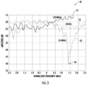
- the graph 50 illustrates propagation frequency dependence for three channels at 225MHZ, 2GHz, and 3.4GHz respectively represented by plot lines 51, 52, and 53.
- the graph 54 illustrates the propagation effects over distance for an RF channel with a plot line 55a representing a 2-ray model and a plot line 55b representing measurements relative to a forward error correction (FEC) threshold 56.
- the graph 57 provides a 3D plot 58 of time-varying frequency response for an RF channel over time and frequency.
- the graphs 50, 54, and 57 illustrate propagation properties as two radios are moving apart, and reveal the occurrence of power nulls 59 which are highly frequency and/or location dependent. Generally speaking, the nulls are defined by downward slopes in the graphs 50, 54, and 57 that dip or fall below a signal threshold (e.g., the FEC threshold 56).
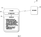
- a radio frequency (RF) communication system 30 may advantageously increase communications link availability in contested RF propagation environments by collecting and utilizing historical RF spectral data for radio channel selection and/or location.
- the system 30 illustratively includes first and second radios 31, 32 which are relatively movable one to the other, meaning that one or more of the radios are mobile.
- the first radio illustratively includes an RF transceiver 33 and a controller 34 coupled to the transceiver, and the second radio may include similar components as well (not shown).
- the RF transceiver 33 is configured to operate on a selected RF channel from among a plurality different RF channels.
- the controller 34 is configured to obtain historical RF spectral data over time, position and RF channel, as the first and second radios 31, 32 move relative to one another (meaning at least one of the radios is mobile), at Block 62.
- the controller 34 is also configured to determine at least one power null from the historical RF spectral data, at Block 63, and dynamically select an RF channel from among the plurality thereof based upon the at least one power null, at Block 65, as will be discussed further below.
- the method of FIG. 6 illustratively concludes at Block 65.
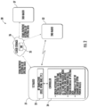
- the system 30 may build a comprehensive database 35 of the historical RF spectral data for the different propagation channels.
- the database 35 is maintained by a cloud storage device or service 36 and shared among multiple radios 31, 32, 37. That is, all of the radios 31, 32, 37 may upload and/or retrieve RF spectral data to/from the database 35 so that the data is shared among them.
- individual databases 35 may be maintained by the radios 31, 32, 37 based upon their own RF spectral data collection for connections to a plurality of radios, and in some embodiments a combination of local and cloud databases may be used. In either case, the historical RF spectral data may be shared among the radios 31, 32, 37.
- a radio travelling along a specified path may be communicating with various base stations along the route, and may share the RF spectral database with other radios that take a similar route to improve signal connectivity and link availability for the latter.
- radios have a-priori knowledge of the RF channel characteristics and improve connectivity including but not limited with mechanisms such as a-priori handover, and a-priori boost of link data rates in sections with favorable RF channels.
- the RF transceiver 33 operates using Direct Sequence Spread Spectrum (DSSS) and Orthogonal Frequency Division Multiplexing (OFDM), although other communications formats may be used as well in different embodiments.
- DSSS Direct Sequence Spread Spectrum
- OFDM Orthogonal Frequency Division Multiplexing
- the historical RF spectral data may be obtained (Block 72) using spectral sensing, which gives a broad spectrum overview and enables characterization. Spectral sensing output helps narrow down available channels that are possible candidates. Furthermore, channel sounding may also be used to send signals (which can be communications signals) to probe various channels properties (e.g., extracting a channel's transfer function). Locations can be obtained via Global Positioning System (GPS) or similar systems that provides users with positioning, navigation, and timing (PNT) services.
- GPS Global Positioning System
- PNT positioning, navigation, and timing
- the latter enable determination of relative timing between transmitter and receiver, which in turn allows for Position Location Information (PLI), even in GPS-denied areas.
- PKI Position Location Information
- One or more of these and other optional measurements e.g., Signal-to-Noise Ratio (SNR), Eb/No, location, spectral picture, Received Signal Strength Indicator (RSSI), Packet Error Rate (PER), interference power, noise figure analysis, etc.
- SNR Signal-to-Noise Ratio
- RSSI Received Signal Strength Indicator
- PER Packet Error Rate
- the information in the database 35 may be considered to be multidimensional in some implementations. In typical systems, much of the above-noted information is promptly discarded after its immediate use. However, by retaining such data and combining this with frequency agility and machine learning (ML)/artificial intelligence (AI), the radios 31, 32, 37 may advantageously provide a more reliable channel/communications link and rapid switching to the best available channel in any given moment based on the outputs from the intelligent algorithm.
- ML/AI models can be used. Some examples include but are not limited to Artificial Neural Networks (ANNs), especially Deep learning approaches, Support-Vector Machines (SVMs), decision tree learning, Bayesian networks, federated learning, etc.
- the algorithm not only learns and predicts based on passive observations, but also includes an agent interacting with the environment to learn and take actions that maximize the chance of maintaining a reliable link as well as avoid intentional and non-intentional jamming.
- the agent also uses game theory to optimize link availability.
- the learning algorithms build a generalized model from the data obtained from the past links, channel identification processes and jammers identified, preferring a reinforcement learning, maximizing a cumulative reward of a stable, fast communications link.
- the intelligent algorithm may use measurements in the database 35 to provide optimized recommendations for channel (center frequency) hop, and/or suggestion for a location move. This may be conceptually considered as opportunistic channel hopping, as the radios 31, 32, 37 use channels with the best opportunity to establish a communications link in a given moment and space.
- the links operate in channels that have the best propagation properties at any given time and in any given space. In other words, this helps to avoid channels with high degradation either due to multipath or jamming.
- the radios 31, 32, 37 may advantageously notify the user to change location (Block 74) and/or channel hop to a frequency that has an upward slope out of or away from a null (Blocks 76-77), and thus provide a reliable link.
- the speed at which channel reallocations are executed may be enhanced through hardware implementations so that maximum data link availability is achieved, although software implementations may also be used.
- Some of the hardware modifications may include, but are not limited to: mechanisms for fast carrier frequency setting and fast acquisition at the frequency hop; multiple parallel waveform support; and support for multitude disparate orthogonal frequency bands such as in very different frequency regions so a large frequency hop (as opposed to regular frequency hopping as known in frequencyhoping-spread-spectrum systems) can be made to support the approach.
- Multitude of very-disparate frequency bands enables implementation of a measurement-based game theoretic framework in a way where the link iteratively and selfishly adapts its strategy as the best response to the strategies of one or more jammers. Since jamming is a game of resources, with jammer resources limited, the jammer resources can be spread too thinly to be effective.
- the intelligent algorithm may suggest geographical moves to enable best communications links. These capabilities may also be combined with anti-jam (AJ) and low-probability of detection (LPD) capabilities inherent to some modern waveforms, for example.
- AJ anti-jam
- LPD low-probability of detection
- specialized hardware such as Xilinx RFSoC or ASICs with multiple ADCs and DACs connected to RF chains of various RF frequency bands and bandwidths can be used to sense the RF spectrum and dynamically exploit available channels.
- a map (e.g., geographical maps of the RF propagation environment) may be displayed (Block 75) for an operator along with an appropriate relocation point to get away from the detected null.
- Some conventional approaches provide static and predetermined RF propagation maps which are generated "once-for-all-time", which do not contain new realities and do not allow for the highly dynamic nature of RF propagation, jamming and differences between radios.
- maps may be dynamically constructed using measurements from the radios 31, 32, 37. This allows for an operator to achieve a more reliable channel communications link where the radio may not only hop to the best available channel in any given moment, but also suggest geographical moves to enable best communications links.
- the system 30 accordingly provides intelligent, datafusion driven opportunistic channel hopping to help maximize control and data link continuity.
- the links operate in channels that have the best propagation properties at any given time.
- channel allocation is typically rigid and predetermined, and there is no adjustability to current channel conditions, nor the capability for interference/jamming avoidance using channel hopping.
- channel selection may be based on an intelligent algorithm that uses a database which accommodates multiple sources of spectral data. The data is collected and processed in real-time to provide desired prediction capabilities (e.g., predicting frequency-dependent signal strengths in radios moving apart).
- data collection may include spectral sensing, channel sounding, Eb/No, RSSI, location, time, regulatory constraints, adversaries jamming patterns, past observations, etc.
- channel hopping may occur in real-time and is enabled by mechanisms such as frequency agility and fast (HDL) processing.
- HDL frequency agility and fast
- Spectral sensing gives a broad spectrum overview and enables characterization. Sensing output narrows down available channels/holes that are possible sounding candidates.
- spectral sensing is typically not used dynamically. That is, frequency allocation is predetermined and fixed and when the channel changes enough, the link is lost. As such, suddenly appearing interference/jamming signals cannot be detected nor characterized.
- sensing the entire instantaneous bandwidth in hardware may be used to reduce unobserved time durations and enable efficient channel allocation, even for very dynamic RF environments.
- a multiphase VHDL (CHSIC Hardware Description Language) implementation may be used to enable real-time or near-real-time continual spectral sensing, for example.
- a signal is sent through a "candidate channel.” In some embodiments, this can be done using (highly DSSS) spread waveforms. Frequency response of the channel may be extracted from the received signal/waveform. In this way, waveforms may be used not just as a comms link, but also for channel sounding.
- the present approach also allows for multichannel channel sounding on top of legacy waveforms. That is, whereas conventional approaches typically do not allow non-spread waveforms to coexist in the same channel, the present approach allows waveforms such as highly-spread DSSS waveforms from L3Harris with LPD to be overlaid on top of legacy waveforms (providing the data link) to provide control and channel sounding. Moreover, the legacy waveform may experience minimal or no degradation.
- the RF transceiver 33 may include a RAKE receiver, as shown in FIG. 2 , which processes a combination of the weighted statistics and collects the energy that arrives at the receiver via a large number of propagation paths.
- High diversity may be enabled by a highly-spread (highresolution chip rate) waveform.
- DSSS permits the resolution of a number of different (multi)paths, providing a certain amount of diversity.
- the RAKE receiver uses diversity by properly combining multipath components that the spread-spectrum receiver is able to resolve.
- a high chip rate enables a high number of resolvable components to be obtained.
Landscapes
- Engineering & Computer Science (AREA)
- Signal Processing (AREA)
- Computer Networks & Wireless Communication (AREA)
- Quality & Reliability (AREA)
- Mobile Radio Communication Systems (AREA)
- Transmitters (AREA)
- Transceivers (AREA)
Description
- The present application relates to communications systems and, more particularly, to radio frequency (RF) communications systems and related methods.
- Mobile radios may be deployed in numerous environments for various purposes. For example, in many applications it is desirable to transmit information from a remote location to a base station or other mobile radios in real time. However, limited communication ranges and free line of sight may make direct transmissions from distant targets impossible, such as when operating over rough terrain and long distances. Problems may also arise in contested RF propagation environments such as those involving densely occupied radio frequency (RF) spectrum multitude, interference or jamming signals, multipath channels such as those found in urban areas, rural areas, mountains or areas with dense foliage to name just a few.
- One approach to mitigating the effects of multipath is set forth in
U.S. Pat. No. 8,363,700 to Michaels et al. This patent discloses a receiver in a communications system that includes an antenna system for receiving a composite signal comprising multi-path components associated with the multi-path images of a transmitted signal. The receiver also includes a correlation system for correlating the received composite signal
with a spreading sequence using different time-offset values to generate time-offset de-spread signals associated with at least a portion the multi-path images, where the spreading sequence is based on sequence of discrete-time chaotic samples. The receiver further includes receiver fingers for generating synchronized de-spread signals from the time-offset de-spread signals based at least on said time-offset values. The receiver also includes a combiner for combining the de-spread signals into a combined coherent de-spread signal.
DocumentUS2017/055266 discloses technologies for providing a transition between predictive and mobile-assisted spectral allocation, wherein wireless devices may be enabled to determine adequacy of their allocated spectral path to meet their communication needs by analyzing signal-to-noise ratios (SNRs) of their assigned sub-carriers. If a wireless device determines a current sub-carrier to be inadequate based on the analysis, d may send information associated with preferred sub-carriers to a base station. The base station may determine one or more nearby good clusters based on a comparison of a sequence of received preferred sub-carriers and the spectral paths represented by the nearby duster centers, and select a re-allocated spectral path with shortest information distance to the sequence of preferred sub-carriers. - Despite the advantages of such systems, further enhancements in RF communications systems to facilitate channel switching in degraded signal environments may be desirable.
- A radio frequency (RF) communication system may include a first radio and a second radio being relatively movable. The first radio may include an RF transceiver configured to operate on a selected RF channel from among a plurality of different RF channels, and a controller coupled to the RF transceiver. The controller is configured to obtain historical RF spectral data over time, position and RF channel, as the first and second radios move relative to one another, determine at least one power null from the historical RF spectral data, and dynamically select an RF channel from among the plurality thereof based upon the at least one power null.
- The controller is configured to dynamically select the RF channel by switching from an RF channel along a downward slope relative to the at least one null and to another RF channel along an upward slope relative to the at least one null.
- By way of example, the controller may be configured to perform channel sounding to obtain the historical RF spectral data. Also by way of example, the controller may be configured to perform spectral sensing to obtain the historical RF spectral data.
- In some embodiments, the controller may be further configured to display a map with a relocation point thereon based upon the historical RF spectral data. The controller may also be configured to cause the RF receiver to switch frequencies based upon the historical RF spectral data in an example embodiment.
- A related radio, such as the one described briefly above, and method for using the radio are also provided. The method may include obtaining historical RF spectral data over time, position and RF channel as the radio moves relative to another radio, determining at least one power null from the historical RF spectral data, and dynamically selecting an RF channel from among the plurality thereof based upon the at least one power null.
-
-
FIG. 1 is a schematic block diagram of a radio frequency (RF) communication system providing dynamic channel switching based upon historical RF spectral data in accordance with an example embodiment. -
FIG. 2 is a schematic block diagram of an example implementation of the system ofFIG. 1 utilizing cloud storage for the historical RF spectral data. -
FIGS. 3-5 are graphs illustrating time and frequency variations in RF propagation channels for which historical RF spectral data may be collected by the systems ofFIGS. 1 and2 . -
FIGS. 6 and7 are flow diagrams illustrating example method aspects associated with the systems ofFIGS. 1 and2 . - The present description is made with reference to the accompanying drawings, in which exemplary embodiments are shown. However, many different embodiments may be used, and thus the description should not be construed as limited to the particular embodiments set forth herein. Rather, these embodiments are provided so that this disclosure will be thorough and complete. Like numbers refer to like elements throughout.
- Referring initially to the
graphs FIGS. 3-5 , and by way of background, radio propagation channels typically experience a variety of environmental propagation effects. For example, these propagation effects may occur in contested RF propagation environments, such as those involving densely occupied RF spectrum multitude, interference or jamming signals, and multipath channels such as those found in urban areas, rural areas, mountains, or areas with dense foliage. Such propagation effects (e.g., multipath/reflection, diffraction, refraction, attenuation, scattering, depolarization, etc.) strongly depend on the carrier frequency (channel) and vary with time and space. - The
graph 50 illustrates propagation frequency dependence for three channels at 225MHZ, 2GHz, and 3.4GHz respectively represented byplot lines graph 54 illustrates the propagation effects over distance for an RF channel with aplot line 55a representing a 2-ray model and aplot line 55b representing measurements relative to a forward error correction (FEC)threshold 56. Thegraph 57 provides a3D plot 58 of time-varying frequency response for an RF channel over time and frequency. Thegraphs power nulls 59 which are highly frequency and/or location dependent. Generally speaking, the nulls are defined by downward slopes in thegraphs - Referring additionally to
FIG. 1 and the flow diagram 60 ofFIG. 6 , a radio frequency (RF)communication system 30 may advantageously increase communications link availability in contested RF propagation environments by collecting and utilizing historical RF spectral data for radio channel selection and/or location. Thesystem 30 illustratively includes first andsecond radios RF transceiver 33 and acontroller 34 coupled to the transceiver, and the second radio may include similar components as well (not shown). TheRF transceiver 33 is configured to operate on a selected RF channel from among a plurality different RF channels. Beginning atBlock 61, thecontroller 34 is configured to obtain historical RF spectral data over time, position and RF channel, as the first andsecond radios Block 62. Thecontroller 34 is also configured to determine at least one power null from the historical RF spectral data, atBlock 63, and dynamically select an RF channel from among the plurality thereof based upon the at least one power null, atBlock 65, as will be discussed further below. The method ofFIG. 6 illustratively concludes atBlock 65. - More particularly, the
system 30 may build acomprehensive database 35 of the historical RF spectral data for the different propagation channels. In the example illustrated inFIG. 2 , thedatabase 35 is maintained by a cloud storage device orservice 36 and shared amongmultiple radios radios database 35 so that the data is shared among them. In other embodiments,individual databases 35 may be maintained by theradios radios RF transceiver 33 operates using Direct Sequence Spread Spectrum (DSSS) and Orthogonal Frequency Division Multiplexing (OFDM), although other communications formats may be used as well in different embodiments. - Referring additionally to the flow diagram 70 of
FIG. 7 , beginning atBlock 71, the historical RF spectral data may be obtained (Block 72) using spectral sensing, which gives a broad spectrum overview and enables characterization. Spectral sensing output helps narrow down available channels that are possible candidates. Furthermore, channel sounding may also be used to send signals (which can be communications signals) to probe various channels properties (e.g., extracting a channel's transfer function). Locations can be obtained via Global Positioning System (GPS) or similar systems that provides users with positioning, navigation, and timing (PNT) services. In some embodiments where the RF transceivers use appropriate waveforms, the latter enable determination of relative timing between transmitter and receiver, which in turn allows for Position Location Information (PLI), even in GPS-denied areas. One or more of these and other optional measurements (e.g., Signal-to-Noise Ratio (SNR), Eb/No, location, spectral picture, Received Signal Strength Indicator (RSSI), Packet Error Rate (PER), interference power, noise figure analysis, etc.) are loaded in memory and retained for further processing and channel selection decision making. - As such, the information in the
database 35 may be considered to be multidimensional in some implementations. In typical systems, much of the above-noted information is promptly discarded after its immediate use. However, by retaining such data and combining this with frequency agility and machine learning (ML)/artificial intelligence (AI), theradios database 35 to provide optimized recommendations for channel (center frequency) hop, and/or suggestion for a location move. This may be conceptually considered as opportunistic channel hopping, as theradios - More particularly, by detecting channel degradation as the link is on a downward slope relative to or into a null as discussed above (Block 73), the
radios - Where a relocation change is appropriate, a map (e.g., geographical maps of the RF propagation environment) may be displayed (Block 75) for an operator along with an appropriate relocation point to get away from the detected null. Some conventional approaches provide static and predetermined RF propagation maps which are generated "once-for-all-time", which do not contain new realities and do not allow for the highly dynamic nature of RF propagation, jamming and differences between radios. However, in accordance with the present approach, maps may be dynamically constructed using measurements from the
radios FIG. 7 illustratively concludes atBlock 78. - The
system 30 accordingly provides intelligent, datafusion driven opportunistic channel hopping to help maximize control and data link continuity. The links operate in channels that have the best propagation properties at any given time. In conventional approaches, channel allocation is typically rigid and predetermined, and there is no adjustability to current channel conditions, nor the capability for interference/jamming avoidance using channel hopping. Yet, in accordance with the present approach, channel selection may be based on an intelligent algorithm that uses a database which accommodates multiple sources of spectral data. The data is collected and processed in real-time to provide desired prediction capabilities (e.g., predicting frequency-dependent signal strengths in radios moving apart). As noted above, data collection may include spectral sensing, channel sounding, Eb/No, RSSI, location, time, regulatory constraints, adversaries jamming patterns, past observations, etc. Moreover, channel hopping may occur in real-time and is enabled by mechanisms such as frequency agility and fast (HDL) processing. The automated nature makes channel hopping fast and viable in situations where manual channel hopping would make it at least very inconvenient/tiresome and often impossible due speed of change required. - Spectral sensing gives a broad spectrum overview and enables characterization. Sensing output narrows down available channels/holes that are possible sounding candidates. In conventional implementations, spectral sensing is typically not used dynamically. That is, frequency allocation is predetermined and fixed and when the channel changes enough, the link is lost. As such, suddenly appearing interference/jamming signals cannot be detected nor characterized. In accordance with the present approach, sensing the entire instantaneous bandwidth in hardware may be used to reduce unobserved time durations and enable efficient channel allocation, even for very dynamic RF environments. In some embodiments, a multiphase VHDL (CHSIC Hardware Description Language) implementation may be used to enable real-time or near-real-time continual spectral sensing, for example.
- With regard to channel sounding, in typical approaches the waveforms are not used for channel sensing. However, in accordance with the present approach, a signal is sent through a "candidate channel." In some embodiments, this can be done using (highly DSSS) spread waveforms. Frequency response of the channel may be extracted from the received signal/waveform. In this way, waveforms may be used not just as a comms link, but also for channel sounding.
- The present approach also allows for multichannel channel sounding on top of legacy waveforms. That is, whereas conventional approaches typically do not allow non-spread waveforms to coexist in the same channel, the present approach allows waveforms such as highly-spread DSSS waveforms from L3Harris with LPD to be overlaid on top of legacy waveforms (providing the data link) to provide control and channel sounding. Moreover, the legacy waveform may experience minimal or no degradation.
- In some embodiments, the
RF transceiver 33 may include a RAKE receiver, as shown inFIG. 2 , which processes a combination of the weighted statistics and collects the energy that arrives at the receiver via a large number of propagation paths. High diversity may be enabled by a highly-spread (highresolution chip rate) waveform. DSSS permits the resolution of a number of different (multi)paths, providing a certain amount of diversity. The RAKE receiver uses diversity by properly combining multipath components that the spread-spectrum receiver is able to resolve. A high chip rate enables a high number of resolvable components to be obtained. - The present approach also allows for the interchange of data and optimized channel allocations between
different radios system 30 is particularly advantageous when used for groundbased wireless communication channels, but it may also be used in ground-to-air and air-to-air configurations as well. - Many modifications and other embodiments will come to the mind of one skilled in the art having the benefit of the teachings presented in the foregoing descriptions and the associated drawings. Therefore, it is understood that the disclosure is not to be limited to the specific embodiments disclosed, and that modifications and embodiments are intended to be included within the scope of the appended claims.
Claims (6)
- A radio frequency, hereinafter RF, communication system (30) comprising:
a first radio (31) and a second radio (32) being relatively movable, the first radio (31) comprisingan RF transceiver (33) configured to operate on a selected RF channel from among a plurality of different RF channels, anda controller (34) coupled to the RF transceiver and configured to:obtain historical RF spectral data over time, position and RF channel, as the first and second radios (31, 32) move relative to one another;determine at least one power null from the historical RF spectral data, anddynamically select an RF channel from among the plurality of RF channels based upon the at least one power null;characterized in that the controller (34) is configured to dynamically select the RF channel by switching from an RF channel along a downward slope relative to the at least one power null to another RF channel along an upward slope relative to the at least one power null. - The RF communication system (30) of claim 1 wherein the controller (34) is configured to perform channel sounding to obtain the historical RF spectral data.
- The RF communication system (30) of claim 1 wherein the controller (34) is configured to perform spectral sensing to obtain the historical RF spectral data.
- The RF communication system (30) of claim 1 wherein the controller (34) is further configured to display a map with a relocation point thereon based upon the historical RF spectral data and channel data.
- The RF communication system (30) of claim 1 wherein the controller (34) is further configured to cause an RF receiver of the transceiver (33) to switch frequencies based upon the historical RF spectral and channel data.
- A method for using a radio comprising a radio frequency (RF) transceiver operable over a plurality of different RF channels, the method comprising:obtaining historical RF spectral data over time, position and RF channel as the radio moves relative to another radio;determining at least one power null from the historical RF spectral data; anddynamically selecting an RF channel from among the plurality of RF channels based upon the at least one power null;characterized in that dynamically selecting comprises dynamically selecting the RF channel by switching from an RF channel along a downward slope relative to the at least one power null to another RF channel along an upward slope relative to the at least one power null.
Applications Claiming Priority (1)
| Application Number | Priority Date | Filing Date | Title |
|---|---|---|---|
| US17/454,496 US11856597B2 (en) | 2021-11-11 | 2021-11-11 | Radio frequency (RF) communication system providing channel selection based upon historical RF spectral data and related methods |
Publications (2)
| Publication Number | Publication Date |
|---|---|
| EP4181449A1 EP4181449A1 (en) | 2023-05-17 |
| EP4181449B1 true EP4181449B1 (en) | 2025-05-21 |
Family
ID=84331287
Family Applications (1)
| Application Number | Title | Priority Date | Filing Date |
|---|---|---|---|
| EP22206673.0A Active EP4181449B1 (en) | 2021-11-11 | 2022-11-10 | Radio frequency (rf) communication system providing channel selection based upon historical rf spectral data and related methods |
Country Status (3)
| Country | Link |
|---|---|
| US (1) | US11856597B2 (en) |
| EP (1) | EP4181449B1 (en) |
| IL (1) | IL298066B2 (en) |
Families Citing this family (2)
| Publication number | Priority date | Publication date | Assignee | Title |
|---|---|---|---|---|
| US12568541B2 (en) * | 2022-12-07 | 2026-03-03 | Qualcomm Incorporated | Multiple access point (AP) association |
| CN120743565B (en) * | 2025-09-02 | 2025-11-11 | 中国科学院国家天文台 | A Method and System for Distributed Cooperative Observation and Data Fusion of the FAST Core Array Based on RFSOC |
Family Cites Families (2)
| Publication number | Priority date | Publication date | Assignee | Title |
|---|---|---|---|---|
| US8363700B2 (en) | 2009-07-01 | 2013-01-29 | Harris Corporation | Rake receiver for spread spectrum chaotic communications systems |
| US20170055266A1 (en) | 2013-06-11 | 2017-02-23 | Empire Technology Development Llc | Smooth transition between predictive and mobile-assisted spectral allocation |
-
2021
- 2021-11-11 US US17/454,496 patent/US11856597B2/en active Active
-
2022
- 2022-11-08 IL IL298066A patent/IL298066B2/en unknown
- 2022-11-10 EP EP22206673.0A patent/EP4181449B1/en active Active
Also Published As
| Publication number | Publication date |
|---|---|
| US20230145990A1 (en) | 2023-05-11 |
| US11856597B2 (en) | 2023-12-26 |
| IL298066B2 (en) | 2024-11-01 |
| IL298066B1 (en) | 2024-07-01 |
| EP4181449A1 (en) | 2023-05-17 |
| IL298066A (en) | 2023-06-01 |
Similar Documents
| Publication | Publication Date | Title |
|---|---|---|
| Sallouha et al. | Localization in long-range ultra narrow band IoT networks using RSSI | |
| US11445517B2 (en) | Method and apparatus for signal interference processing | |
| Celebi et al. | Cognitive positioning systems | |
| KR101152572B1 (en) | Cognitive radio cooperative spectrum sensing method and fusion center capable of determining optimal number of secondary users | |
| EP2545726B1 (en) | Radio white space sensing | |
| US7956807B1 (en) | Cognitive positioning system | |
| US20040264403A1 (en) | Definable radio and method of operating a wireless network of same | |
| EP4181449A1 (en) | Radio frequency (rf) communication system providing channel selection based upon historical rf spectral data and related methods | |
| MX2007005097A (en) | Determining a mobile station position based on pertinent location fingerprint data. | |
| WO2011103682A1 (en) | Method and apparatus for opportunistic communication scheduling in a wireless communication network using motion information | |
| US20080153553A1 (en) | Radio communication terminal and radio communication system | |
| Lyazidi et al. | ISAC architecture and sensing topology switching in 6G cellular networks | |
| CN100536594C (en) | Estimation of signal delay | |
| EP2382821B1 (en) | Method for generating cooperation areas in communications networks and corresponding network nodes | |
| Ishida et al. | Evaluation of BLE separate channel fingerprinting in practical environment | |
| Tatino et al. | Learning-based link scheduling in millimeter-wave multi-connectivity scenarios | |
| Nosrati et al. | Cooperative spectrum sensing for beyond-5g networks in fading environments | |
| US12520289B1 (en) | System and method for distributed spectrum monitoring | |
| Elrahim et al. | A Survey for Cognitive Radio Networks | |
| US12580618B1 (en) | Wireless communication device and method for spectrum sensing across multiple frequency bands | |
| CN113852924A (en) | Antenna determination method, antenna determination device, terminal, electronic equipment and storage medium | |
| US12633948B1 (en) | Wireless communication device and method for wideband spectrum monitoring | |
| Li et al. | Interference mitigation between ultra-wideband sensor network and other legal systems | |
| Koudouridis et al. | A method for the generation of radio signal coverage maps for dense networks | |
| Elsner et al. | Non-parametric modeling with Gaussian processes for spatial radio-scene analysis |
Legal Events
| Date | Code | Title | Description |
|---|---|---|---|
| PUAI | Public reference made under article 153(3) epc to a published international application that has entered the european phase |
Free format text: ORIGINAL CODE: 0009012 |
|
| STAA | Information on the status of an ep patent application or granted ep patent |
Free format text: STATUS: REQUEST FOR EXAMINATION WAS MADE |
|
| 17P | Request for examination filed |
Effective date: 20221111 |
|
| AK | Designated contracting states |
Kind code of ref document: A1 Designated state(s): AL AT BE BG CH CY CZ DE DK EE ES FI FR GB GR HR HU IE IS IT LI LT LU LV MC ME MK MT NL NO PL PT RO RS SE SI SK SM TR |
|
| GRAP | Despatch of communication of intention to grant a patent |
Free format text: ORIGINAL CODE: EPIDOSNIGR1 |
|
| STAA | Information on the status of an ep patent application or granted ep patent |
Free format text: STATUS: GRANT OF PATENT IS INTENDED |
|
| INTG | Intention to grant announced |
Effective date: 20250224 |
|
| GRAS | Grant fee paid |
Free format text: ORIGINAL CODE: EPIDOSNIGR3 |
|
| GRAA | (expected) grant |
Free format text: ORIGINAL CODE: 0009210 |
|
| STAA | Information on the status of an ep patent application or granted ep patent |
Free format text: STATUS: THE PATENT HAS BEEN GRANTED |
|
| AK | Designated contracting states |
Kind code of ref document: B1 Designated state(s): AL AT BE BG CH CY CZ DE DK EE ES FI FR GB GR HR HU IE IS IT LI LT LU LV MC ME MK MT NL NO PL PT RO RS SE SI SK SM TR |
|
| P01 | Opt-out of the competence of the unified patent court (upc) registered |
Free format text: CASE NUMBER: APP_17684/2025 Effective date: 20250410 |
|
| REG | Reference to a national code |
Ref country code: GB Ref legal event code: FG4D |
|
| REG | Reference to a national code |
Ref country code: CH Ref legal event code: EP |
|
| REG | Reference to a national code |
Ref country code: DE Ref legal event code: R096 Ref document number: 602022014916 Country of ref document: DE |
|
| REG | Reference to a national code |
Ref country code: IE Ref legal event code: FG4D |
|
| REG | Reference to a national code |
Ref country code: NL Ref legal event code: MP Effective date: 20250521 |
|
| PG25 | Lapsed in a contracting state [announced via postgrant information from national office to epo] |
Ref country code: FI Free format text: LAPSE BECAUSE OF FAILURE TO SUBMIT A TRANSLATION OF THE DESCRIPTION OR TO PAY THE FEE WITHIN THE PRESCRIBED TIME-LIMIT Effective date: 20250521 Ref country code: PT Free format text: LAPSE BECAUSE OF FAILURE TO SUBMIT A TRANSLATION OF THE DESCRIPTION OR TO PAY THE FEE WITHIN THE PRESCRIBED TIME-LIMIT Effective date: 20250922 Ref country code: ES Free format text: LAPSE BECAUSE OF FAILURE TO SUBMIT A TRANSLATION OF THE DESCRIPTION OR TO PAY THE FEE WITHIN THE PRESCRIBED TIME-LIMIT Effective date: 20250521 |
|
| REG | Reference to a national code |
Ref country code: LT Ref legal event code: MG9D |
|
| PG25 | Lapsed in a contracting state [announced via postgrant information from national office to epo] |
Ref country code: NO Free format text: LAPSE BECAUSE OF FAILURE TO SUBMIT A TRANSLATION OF THE DESCRIPTION OR TO PAY THE FEE WITHIN THE PRESCRIBED TIME-LIMIT Effective date: 20250821 Ref country code: GR Free format text: LAPSE BECAUSE OF FAILURE TO SUBMIT A TRANSLATION OF THE DESCRIPTION OR TO PAY THE FEE WITHIN THE PRESCRIBED TIME-LIMIT Effective date: 20250822 |
|
| PG25 | Lapsed in a contracting state [announced via postgrant information from national office to epo] |
Ref country code: NL Free format text: LAPSE BECAUSE OF FAILURE TO SUBMIT A TRANSLATION OF THE DESCRIPTION OR TO PAY THE FEE WITHIN THE PRESCRIBED TIME-LIMIT Effective date: 20250521 Ref country code: PL Free format text: LAPSE BECAUSE OF FAILURE TO SUBMIT A TRANSLATION OF THE DESCRIPTION OR TO PAY THE FEE WITHIN THE PRESCRIBED TIME-LIMIT Effective date: 20250521 |
|
| PG25 | Lapsed in a contracting state [announced via postgrant information from national office to epo] |
Ref country code: BG Free format text: LAPSE BECAUSE OF FAILURE TO SUBMIT A TRANSLATION OF THE DESCRIPTION OR TO PAY THE FEE WITHIN THE PRESCRIBED TIME-LIMIT Effective date: 20250521 |
|
| PG25 | Lapsed in a contracting state [announced via postgrant information from national office to epo] |
Ref country code: HR Free format text: LAPSE BECAUSE OF FAILURE TO SUBMIT A TRANSLATION OF THE DESCRIPTION OR TO PAY THE FEE WITHIN THE PRESCRIBED TIME-LIMIT Effective date: 20250521 |
|
| PG25 | Lapsed in a contracting state [announced via postgrant information from national office to epo] |
Ref country code: RS Free format text: LAPSE BECAUSE OF FAILURE TO SUBMIT A TRANSLATION OF THE DESCRIPTION OR TO PAY THE FEE WITHIN THE PRESCRIBED TIME-LIMIT Effective date: 20250821 |
|
| PG25 | Lapsed in a contracting state [announced via postgrant information from national office to epo] |
Ref country code: IS Free format text: LAPSE BECAUSE OF FAILURE TO SUBMIT A TRANSLATION OF THE DESCRIPTION OR TO PAY THE FEE WITHIN THE PRESCRIBED TIME-LIMIT Effective date: 20250921 |
|
| PG25 | Lapsed in a contracting state [announced via postgrant information from national office to epo] |
Ref country code: LV Free format text: LAPSE BECAUSE OF FAILURE TO SUBMIT A TRANSLATION OF THE DESCRIPTION OR TO PAY THE FEE WITHIN THE PRESCRIBED TIME-LIMIT Effective date: 20250521 |
|
| REG | Reference to a national code |
Ref country code: AT Ref legal event code: MK05 Ref document number: 1797760 Country of ref document: AT Kind code of ref document: T Effective date: 20250521 |
|
| PGFP | Annual fee paid to national office [announced via postgrant information from national office to epo] |
Ref country code: DE Payment date: 20251128 Year of fee payment: 4 |
|
| PG25 | Lapsed in a contracting state [announced via postgrant information from national office to epo] |
Ref country code: DK Free format text: LAPSE BECAUSE OF FAILURE TO SUBMIT A TRANSLATION OF THE DESCRIPTION OR TO PAY THE FEE WITHIN THE PRESCRIBED TIME-LIMIT Effective date: 20250521 Ref country code: AT Free format text: LAPSE BECAUSE OF FAILURE TO SUBMIT A TRANSLATION OF THE DESCRIPTION OR TO PAY THE FEE WITHIN THE PRESCRIBED TIME-LIMIT Effective date: 20250521 Ref country code: SM Free format text: LAPSE BECAUSE OF FAILURE TO SUBMIT A TRANSLATION OF THE DESCRIPTION OR TO PAY THE FEE WITHIN THE PRESCRIBED TIME-LIMIT Effective date: 20250521 |
|
| PGFP | Annual fee paid to national office [announced via postgrant information from national office to epo] |
Ref country code: IT Payment date: 20251201 Year of fee payment: 4 |
|
| PGFP | Annual fee paid to national office [announced via postgrant information from national office to epo] |
Ref country code: FR Payment date: 20251125 Year of fee payment: 4 |
|
| PGFP | Annual fee paid to national office [announced via postgrant information from national office to epo] |
Ref country code: TR Payment date: 20251023 Year of fee payment: 4 |
|
| PG25 | Lapsed in a contracting state [announced via postgrant information from national office to epo] |
Ref country code: CZ Free format text: LAPSE BECAUSE OF FAILURE TO SUBMIT A TRANSLATION OF THE DESCRIPTION OR TO PAY THE FEE WITHIN THE PRESCRIBED TIME-LIMIT Effective date: 20250521 |
|
| PG25 | Lapsed in a contracting state [announced via postgrant information from national office to epo] |
Ref country code: EE Free format text: LAPSE BECAUSE OF FAILURE TO SUBMIT A TRANSLATION OF THE DESCRIPTION OR TO PAY THE FEE WITHIN THE PRESCRIBED TIME-LIMIT Effective date: 20250521 |
|
| PG25 | Lapsed in a contracting state [announced via postgrant information from national office to epo] |
Ref country code: SK Free format text: LAPSE BECAUSE OF FAILURE TO SUBMIT A TRANSLATION OF THE DESCRIPTION OR TO PAY THE FEE WITHIN THE PRESCRIBED TIME-LIMIT Effective date: 20250521 |
|
| REG | Reference to a national code |
Ref country code: DE Ref legal event code: R097 Ref document number: 602022014916 Country of ref document: DE |
|
| PG25 | Lapsed in a contracting state [announced via postgrant information from national office to epo] |
Ref country code: RO Free format text: LAPSE BECAUSE OF FAILURE TO SUBMIT A TRANSLATION OF THE DESCRIPTION OR TO PAY THE FEE WITHIN THE PRESCRIBED TIME-LIMIT Effective date: 20250521 |
|
| PLBE | No opposition filed within time limit |
Free format text: ORIGINAL CODE: 0009261 |
|
| STAA | Information on the status of an ep patent application or granted ep patent |
Free format text: STATUS: NO OPPOSITION FILED WITHIN TIME LIMIT |
|
| REG | Reference to a national code |
Ref country code: CH Ref legal event code: L10 Free format text: ST27 STATUS EVENT CODE: U-0-0-L10-L00 (AS PROVIDED BY THE NATIONAL OFFICE) Effective date: 20260402 |
|
| 26N | No opposition filed |
Effective date: 20260224 |