EP4181330A1 - A method of producing a sealed connector arrangement, a sealed connector arrangement and use of the method - Google Patents
A method of producing a sealed connector arrangement, a sealed connector arrangement and use of the method Download PDFInfo
- Publication number
- EP4181330A1 EP4181330A1 EP21207760.6A EP21207760A EP4181330A1 EP 4181330 A1 EP4181330 A1 EP 4181330A1 EP 21207760 A EP21207760 A EP 21207760A EP 4181330 A1 EP4181330 A1 EP 4181330A1
- Authority
- EP
- European Patent Office
- Prior art keywords
- terminal
- sealing material
- connector arrangement
- channel system
- aggregate
- Prior art date
- Legal status (The legal status is an assumption and is not a legal conclusion. Google has not performed a legal analysis and makes no representation as to the accuracy of the status listed.)
- Granted
Links
Images


Classifications
-
- H—ELECTRICITY
- H01—ELECTRIC ELEMENTS
- H01R—ELECTRICALLY-CONDUCTIVE CONNECTIONS; STRUCTURAL ASSOCIATIONS OF A PLURALITY OF MUTUALLY-INSULATED ELECTRICAL CONNECTING ELEMENTS; COUPLING DEVICES; CURRENT COLLECTORS
- H01R13/00—Details of coupling devices of the kinds covered by groups H01R12/70 or H01R24/00 - H01R33/00
- H01R13/46—Bases; Cases
- H01R13/52—Dustproof, splashproof, drip-proof, waterproof, or flameproof cases
- H01R13/5216—Dustproof, splashproof, drip-proof, waterproof, or flameproof cases characterised by the sealing material, e.g. gels or resins
-
- B—PERFORMING OPERATIONS; TRANSPORTING
- B29—WORKING OF PLASTICS; WORKING OF SUBSTANCES IN A PLASTIC STATE IN GENERAL
- B29C—SHAPING OR JOINING OF PLASTICS; SHAPING OF MATERIAL IN A PLASTIC STATE, NOT OTHERWISE PROVIDED FOR; AFTER-TREATMENT OF THE SHAPED PRODUCTS, e.g. REPAIRING
- B29C39/00—Shaping by casting, i.e. introducing the moulding material into a mould or between confining surfaces without significant moulding pressure; Apparatus therefor
- B29C39/02—Shaping by casting, i.e. introducing the moulding material into a mould or between confining surfaces without significant moulding pressure; Apparatus therefor for making articles of definite length, i.e. discrete articles
- B29C39/10—Shaping by casting, i.e. introducing the moulding material into a mould or between confining surfaces without significant moulding pressure; Apparatus therefor for making articles of definite length, i.e. discrete articles incorporating preformed parts or layers, e.g. casting around inserts or for coating articles
-
- B—PERFORMING OPERATIONS; TRANSPORTING
- B29—WORKING OF PLASTICS; WORKING OF SUBSTANCES IN A PLASTIC STATE IN GENERAL
- B29C—SHAPING OR JOINING OF PLASTICS; SHAPING OF MATERIAL IN A PLASTIC STATE, NOT OTHERWISE PROVIDED FOR; AFTER-TREATMENT OF THE SHAPED PRODUCTS, e.g. REPAIRING
- B29C45/00—Injection moulding, i.e. forcing the required volume of moulding material through a nozzle into a closed mould; Apparatus therefor
- B29C45/14—Injection moulding, i.e. forcing the required volume of moulding material through a nozzle into a closed mould; Apparatus therefor incorporating preformed parts or layers, e.g. injection moulding around inserts or for coating articles
- B29C45/14336—Coating a portion of the article, e.g. the edge of the article
- B29C45/14344—Moulding in or through a hole in the article, e.g. outsert moulding
-
- F—MECHANICAL ENGINEERING; LIGHTING; HEATING; WEAPONS; BLASTING
- F42—AMMUNITION; BLASTING
- F42B—EXPLOSIVE CHARGES, e.g. FOR BLASTING, FIREWORKS, AMMUNITION
- F42B3/00—Blasting cartridges, i.e. case and explosive
- F42B3/24—Cartridge closures or seals
-
- F—MECHANICAL ENGINEERING; LIGHTING; HEATING; WEAPONS; BLASTING
- F42—AMMUNITION; BLASTING
- F42C—AMMUNITION FUZES; ARMING OR SAFETY MEANS THEREFOR
- F42C19/00—Details of fuzes
- F42C19/06—Electric contact parts specially adapted for use with electric fuzes
-
- H—ELECTRICITY
- H01—ELECTRIC ELEMENTS
- H01R—ELECTRICALLY-CONDUCTIVE CONNECTIONS; STRUCTURAL ASSOCIATIONS OF A PLURALITY OF MUTUALLY-INSULATED ELECTRICAL CONNECTING ELEMENTS; COUPLING DEVICES; CURRENT COLLECTORS
- H01R43/00—Apparatus or processes specially adapted for manufacturing, assembling, maintaining, or repairing of line connectors or current collectors or for joining electric conductors
- H01R43/005—Apparatus or processes specially adapted for manufacturing, assembling, maintaining, or repairing of line connectors or current collectors or for joining electric conductors for making dustproof, splashproof, drip-proof, waterproof, or flameproof connection, coupling, or casing
-
- B—PERFORMING OPERATIONS; TRANSPORTING
- B29—WORKING OF PLASTICS; WORKING OF SUBSTANCES IN A PLASTIC STATE IN GENERAL
- B29C—SHAPING OR JOINING OF PLASTICS; SHAPING OF MATERIAL IN A PLASTIC STATE, NOT OTHERWISE PROVIDED FOR; AFTER-TREATMENT OF THE SHAPED PRODUCTS, e.g. REPAIRING
- B29C45/00—Injection moulding, i.e. forcing the required volume of moulding material through a nozzle into a closed mould; Apparatus therefor
- B29C45/14—Injection moulding, i.e. forcing the required volume of moulding material through a nozzle into a closed mould; Apparatus therefor incorporating preformed parts or layers, e.g. injection moulding around inserts or for coating articles
- B29C45/14336—Coating a portion of the article, e.g. the edge of the article
- B29C2045/14459—Coating a portion of the article, e.g. the edge of the article injecting seal elements
Definitions
- the present invention refers to a method of producing a sealed connector arrangement, a sealed connector arrangement and the use of the method to produce a sealed connector arrangement to be used in a road vehicle or in a wearable electronic device.
- sealed connectors It is well known in the art to use sealed connectors in equipment that get washed or that is subjected to a dusty or humid environment in order of providing a protection against ingress of humidity and dust.
- One well known measure to provide sealed connectors is to fill the interior of the connector housing with a sealing material that effectively seals off the interfaces between the housing parts as such and also between the housing and the cable that extends into the housing.
- such sealing material does only seal off the connector as such and not the interface between two mating connectors or between the connector and the electronic component to which the connector is configured to be connected. This is typically made by arranging one or more flexible sealings in and around such interface. This is however complicated since it is made during assembly and it is very costly, no matter if it is made manually or in an automated manner.
- Another object of the invention is to safeguard the provision of a sealed connector arrangement also for the aftermarket.
- Yet another object is that the method and arrangement should be applicable not only for connectors of electrical type but also for connectors of optical type.
- Still another object is that the method and arrangement should be applicable no matter type of terminals that may be used in the connector arrangement.
- a method of producing a sealed connector arrangement by means of a first terminal aggregate and a connector
- a method of producing a sealed connector arrangement wherein the sealing is provided by injecting a sealing material into an internal channel system of the housing.
- the injection of sealing material is made in a condition when the connector is connected to the first terminal aggregate thereby forming the electrical and/or optical contact between the first and the second terminal aggregates.
- the channel system to be filled with a sealing material is defined partly by the connector and its housing and partly by the first terminal aggregate and hence also by the interface between the first terminal aggregate and the second terminal aggregate.
- the connector with its housing which supports the second terminal aggregate and which in turn is connected to the first terminal aggregate will, after filling, form one sealed unit in which the area surrounding the interface between the interconnected first and second terminal aggregates is sealed-off and hence protected from intrusion of humidity and dust. Since the first and second terminal aggregates are interconnected before the sealing material is injected, the sealing-off does not impact the communication between the two terminal aggregates. Further, the sealing material prevents dis-connection of the two terminal aggregates.
- the sealing material may be forced all the way from the inlet opening of the channel system to and out of the outlet opening of the channel system, i.e. providing a complete filling.
- the sealing material may be forced all the way from the inlet opening of the channel system to a vicinity of the first outlet opening but not out of the same.
- This may be seen as a partial filling.
- the filling should be made to such extent that the sealing material seals-off the interface between the first and the second terminal aggregates from the exterior without impacting the power/signal transmission therebetween.
- both degrees of filling may be used on the manufacturers choice to provide a sealed connector arrangement that is sufficiently sealed to meet a given standard or purpose.
- One advantage of a complete filling over a partial filling is that the complete filling better facilitates a visual quality inspection to see any pores or the like that may indicate or allow a possible intrusion of dust/humidity.
- the inlet opening to the channel system will be automatically sealed-off since the sealing material is injected via the same.
- the degree of filling depends on parameters such viscosity and amount of sealing material injected.
- the method provides a sealed connector arrangement, but it also provides a tamper-proof connector arrangement that facilitates the process when installing a component using such sealed connector arrangement in its intended position, e.g. in a road vehicle or in a wearable electronic device. Further, it facilitates the after-market in the event such sealed connector arrangement is provided as a spare part. This will by default be provided in a sealed condition without any separate needs to add additional sealings or gaskets.
- the channel system may further comprise a second outlet opening being arranged adjacent the cable opening, wherein the act of injecting sealing material into the inlet opening further comprises forcing the sealing material via the channel system to a vicinity of, or out of the second outlet opening, thereby sealing-off an interface between the cable and the cable opening of the housing.
- the cable is preferably arranged substantially coaxially with the cable opening of the housing. This means that the second outlet opening will have a substantially ring-shaped cross-sectional area. By sealing-off this interface, any dust or humidity is prevented from entering the connector arrangement via the cable opening. Since the sealing-off is made from the inside-out, an efficient sealing-off is provided for without the need for any additional/separate sealing members.
- the sealing material contributes to the fixation of the cable to the housing and does hence act as a cable lock which prevents the cable from being pulled out.
- the latter as such may be seen as an extra safety measure.
- this kind of fixation of the cable further contributes to the provision of a tamper-proof unit on the after-market.
- the channel system may further comprise a third outlet opening being arranged adjacent a free end surface of the housing configured to face the first terminal aggregate in a condition when the connector is connected to the first terminal aggregate, wherein the act of injecting sealing material into the inlet opening further comprises forcing the sealing material via the channel system to a vicinity of, or out of the third outlet opening, thereby sealing-off an interface between the free end surface of the housing and the first terminal aggregate.
- the interface between the free end surface of the housing and the first terminal aggregate may be seen as a gap which typically has a substantially lateral extension whereas the engagement between the first and second terminal aggregates typically has a substantially axial extension.
- the gap may have a substantially 360 degrees circumferential extension.
- the channel system must not be limited to one, two or three outlet openings, but that more than three outlet openings may be applied. No matter number of outlet openings, the cross-sectional areas of the one or more outlet opening(s) may differ depending on position and purpose.
- the sealing material may be injected into the inlet opening by using a pressure in the range of 0-8 bar, more preferred in the range of 2-8 bar and even more preferred in the range of 3-6 bar.
- the pressure depends on parameters such as geometry and volume of the channel, any internal flow restrictions in the channel, type of sealing material, viscosity and any internal temperature differences in the parts making up the connector arrangement. It is advantageous if the pressure is sufficiently high to fill the channel and also force any air that otherwise may be entrapped in the channel to leave the same.
- the method may further comprise the act of hardening the sealing material after injecting the sealing material into the inlet opening.
- the hardening may be made e.g. in room temperature or subjecting the filled connector arrangement to heat, i.e. to a temperature above room temperature.
- the choice of hardening method, temperature and time depends on parameters such as the type of sealing material that is used and allowed cycle time in the production system.
- the channel system of the housing may further comprise at least one vent hole, whereby air in the channel system is allowed to leave the channel system during the act of injecting the sealing material.
- the position of the at least one vent hole and the number of vent holes depends on the overall design and complexity of the channel system. It is preferred that the at least one vent hole is arranged closer to any of the at least one outlet openings than to the inlet opening. Also, it is preferred that the at least one vent hole is smaller than any of the outlet openings.
- a sealed connector arrangement which connector arrangement is manufactured by using the method according to any of claims 1-7.
- the sealed connector arrangement may by way of example be configured to be a part of a road vehicle or a wearable electronic device.
- the wearable electronic device may, as a non-limiting example be a helmet, a backpack, a vest or a hip-protection.
- the first terminal aggregate may be an electric device or a member of an electric device.
- the electric device may be a micro gas generator to be used in an airbag-system or in a piston-based hood lifter of a rad vehicle.
- the electrical device may be configured to form part of a road vehicle or a wearable electronic device.
- the first terminal arrangement may be part of a micro gas generator.
- the first and second terminal aggregates may comprise power connecting members.
- the first and second terminal aggregates may comprise optical connecting members.
- the terminal aggregates may, as non-limiting examples, be of a plug-and-socket type, a fixed contact surface configured to interact with a biased contact surface, a connector of the USB type or a fiber optics connector.
- the first terminal aggregate should be complementary to the second terminal aggregate.
- the skilled person realizes that at least one of the two terminal aggregates may be of a universal type with a plurality of ports but with only relevant ports being wired.
- the invention refers to the use of the method according to any of claims 1-7 to produce a sealed connector arrangement to be used in a road vehicle or in a wearable electronic device.
- the connector arrangement 1 comprises an electronic unit 100 supporting a first terminal aggregate 101 and a connector 200 with a housing 202 which supports a second terminal aggregate 201.
- the first and the second terminal aggregates 101, 201 are, in a condition when connected to each other, configured to form a contact with each other.
- the contact may, depending on the type of terminal aggregate be used to allow a power transmission or a signal transmission, such as an optical signal.
- the connector 200 comprises the housing 202 that as such is well known in the art.
- the housing 202 provides an encapsulation of and supports a terminal aggregate.
- the terminal aggregate of the connector 200 is in the present application referred to as the second terminal aggregate 201.
- the housing 202 comprises a cable opening 203 that is configured to receive a cable 204.
- the cable 204 extends into the housing 202 from an exterior side thereof and is connected to the second terminal aggregate 201 to allow powering thereof or to allow transmission of a signal via said second terminal aggregate 201. Again, this is well known in the art and is not further discussed. Equally well known is the interface between the cable 204 and the second terminal aggregate 201 which is also not disclosed.
- the housing 202 further comprises, also well known in the art, a shielding member 205, typically made of graphite. The skilled person realises that the housing may have numerous different designs with remained function, including the position of the cable opening 203.
- the housing 202 is in its interior provided with a channel system 206.
- the channel system 206 comprises an inlet opening 207 and a first outlet opening 208.
- the first outlet opening 208 is arranged adjacent the second terminal aggregate 201. This is best seen in Fig. 3 .
- the disclosed channel system 206 comprises a second outlet opening 209 which is arranged adjacent the cable opening 203.
- the cable 204 is preferably arranged substantially coaxially with the cable opening 203. This means that the second outlet opening 209 will have a substantially ring-shaped cross-sectional area.
- the sealing material when injecting a sealing material into the inlet opening 207, the sealing material will propagate through the channel system 206, from the inlet opening 207 to a vicinity of, or out of the second outlet opening 209, thereby sealing-off an interface between the cable 204 and the cable opening 203 of the housing 202. By sealing-off this interface any dust or humidity is prevented from entering the connector arrangement 100 via the cable opening 203.
- sealing-off is made from the inside-out, an efficient sealing-off is provided for without the need for any additional/separate sealing members.
- sealing material contributes to the fixation of the cable 204 to the housing 202.
- the sealing material hence additionally acts as a cable lock which prevents the cable 204 from being pulled out.
- the disclosed channel system 206 further comprises a third outlet opening 210.
- the third outlet opening 210 is arranged adjacent a free end surface 211 of the housing 202.
- the free end surface 211 is configured to face the first terminal aggregate 101 in a condition when the connector 200 is connected to the first terminal aggregate 101.
- the interface between the free end surface 211 of the housing 202 and the first terminal aggregate 101 may be seen as a gap 212 which typically has a substantially lateral extension whereas the engagement between the first and second terminal aggregates 101, 201 typically has a substantially axial extension.
- "axial" refers to the direction in which the first and second terminal aggregates 101, 201 are moved towards each other to form a connection therebetween.
- the gap 212 may have a substantially 360 degrees circumferential extension.
- the sealing material when injecting a sealing material into the inlet opening 207, the sealing material will propagate through the channel system 206, from the inlet opening 207 to a vicinity of, or out of the third outlet opening 210, thereby sealing-off the third outlet opening 210 from the inside-out and also at least a part of the interface between the free end surface 211 of the housing 202 and the first terminal aggregate 101. Thereby, any dust or humidity is prevented from entering the connector arrangement 100 via such interface and via the third outlet opening 210.
- the channel system 206 must not be limited to one, two or three outlet openings, but that more than three outlet openings may be applied. No matter the number of outlet openings, the cross-sectional areas of the one or more outlet opening(s) may differ depending on position.
- the channel system 206 does further preferably comprise at least one vent hole 214.
- the at least one vent hole 214 allows air that is entrapped in the channel system 206 to leave the system during injection of the sealing material as will be described below.
- the position of the at least one vent hole 214 and the number of vent holes 214 depends on the overall design and complexity of the channel system 206. It is preferred that the at least one vent hole 214 is arranged closer to any of the at least one outlet openings 208, 209, 210 than to the inlet opening 207. Also, it is preferred that the at least one vent hole 214 is smaller than any of the outlet openings 208, 209, 210.
- the first terminal aggregate 101 is disclosed as being supported by and hence constituting a member of an electrical device 300.
- the electrical device 300 may by way of example be configured to constitute a component of a road vehicle or a wearable electronic device.
- the electric device 300 may be a micro gas generator to be used in an airbag-system or in a piston-based hood lifter in a road vehicle.
- the first terminal aggregate 101 may accordingly be part of such micro gas generator, piston-based hood lifter or wearable electronic device.
- the wearable electronic device may, as a non-limiting example be a helmet, a backpack, a vest or a hip-protection.
- the first and second terminal aggregates 101, 201 may comprise power connecting members 113, 213 or optical connecting members.
- the terminal aggregates 101, 201 may, no matter type, as non-limiting examples, be of a plug-and-socket type, a fixed contact surface configured to interact with a biased contact surface, a connector of the USB type or a fiber optics connector.
- the first terminal aggregate 101 may be of a male type and the second terminal aggregate 201 of a female type.
- the first terminal aggregate 101 may be of a female type and the second terminal aggregate 201 of a male type.
- the first terminal aggregate 101 should be complementary to the second terminal aggregate 201.
- the skilled person realizes that at least one of the two terminal aggregates 101, 201 may be of a universal type with a plurality of ports but only with relevant ports being wired and hence intended to be used for the specific intended purpose.
- the method comprises the initial steps of providing 1000 a connector 200 and a first terminal aggregate 101 of the type discussed above, and connecting 2000 the second terminal aggregate 202 of the connector 200 to the first terminal aggregate 101 to thereby form a contact between the first and the second terminal aggregates 101, 201.
- a sealing material 400 is injected 3000 into the channel system 206 via the inlet opening 207.
- the injection is made by a nozzle 500 that is moved into fluid communication with the inlet opening 207 of the channel system 206.
- the nozzle 500 is connected to a non-disclosed dispenser.
- the sealing material 400 is injected into the inlet opening 207 so that the sealing material 400 is forced via the channel system 206 to a vicinity of each and one of the outlet openings 208, 209, 210 of the channel system 206.
- the disclosed embodiment of the channels system 206 comprises a first outlet opening 208, a second outlet opening 209 and a third outlet opening 210, each of them discussed above with reference to Figs 1-3 .
- the sealing material 400 When injecting the sealing material 400 into the inlet opening 207, the sealing material 400 will be forced to fill the channel 206 and be forced to a vicinity of, or out of the first outlet opening 208, thereby sealing-off an interface between the first and the second terminal aggregates 101, 201. It will also be forced to a vicinity of, or out of the second outlet opening 209, thereby sealing-off an interface between the cable 204 and the cable opening 203 of the housing 202. Further, it will be forced to a vicinity of, or out of the third outlet opening 210, thereby sealing-off an interface between the free end surface 211 of the housing 202 and the first terminal aggregate 101.
- the resulting filled channel 206 is illustrated in Figs. 5 and 6 as a solid filling. As is best seen in these two figures, the channel 206 has a three-dimensional extension inside the housing 202 thereby forming a net-like configuration where each outlet opening is part of an individual branch.
- the sealing material 400 will thereby seal-off and thereby prevent intrusion of humidity and dust into the housing 202 and also into the interface between the housing 202 and the first terminal aggregate 101.
- the filling must not be made to such extent that the sealing material 400 exits one or more of the outlet openings 208, 209, 210. It is sufficient that the sealing material 400 reaches the vicinity of any of the respective openings 208, 209, 210 to thereby seal-off the channel 206 and relevant surface portions.
- the sealing material 400 will contribute to fixate the cable 204 to the housing 202. This contributes to the provision of a tamper-proof sealed connector arrangement 1 to the after-market.
- the sealing material 400 may be injected into the inlet opening 207 by using a pressure in the range of 0-8 bar, more preferred 2-8 bar and even more preferred in the range of 3-6 bar.
- the pressure depends on parameters such as geometry and volume of the channel 206, any internal flow restrictions in the channel 206, type of sealing material 400, viscosity and any internal temperature differences in the parts making up the connector arrangement 1. It is advantageous if the pressure is sufficiently high to fill the channel 206 and also force any air that otherwise may be entrapped in the channel to leave the same.
- the sealing material 400 may be a hot melt adhesive or a two-component adhesive. It is to be understood that also other types of adhesives or sealants may be used, either alone or in combination.
- the channel system 206 may be filled, or substantially filled with a first type of sealing material 400, e.g. a hot melt adhesive or a two-component adhesive, whereas any remaining space adjacent any of the one or more outlet openings 208, 209, 210 may be filled with a second type of sealing material 400.
- Such supplementary filling may be made from the exterior side of the housing 202.
- such second type of sealing material 400 may be hardened by another method than the first type adhesive, such as UV heating.
- the sealing material 400 may be forced all the way from the inlet opening 207 of the channel system 206 to and out of the respective outlet opening 208, 209, 210 of the channel system 206, i.e. providing a complete filling as is disclosed in Figs. 7 and 8 .
- the sealing material 400 may be forced all the way from the inlet opening 207 of the channel system 206 to a vicinity of the first outlet opening 208 but not out of the same as is disclosed in Figs. 5 and 6 . This may be seen as a partial filling.
- the filling should be made to such extent that the sealing material 400 seals-off the interface between the first and the second terminal aggregates 101, 201.
- both degrees of filling may be used on the manufacturer's choice to provide a sealed connector arrangement 1 that is sufficiently sealed to meet a given standard.
- One advantage of a complete filling over a partial filling is that the complete filling better facilitates a visual quality inspection to see any pores or the like that may indicate or allow a possible leakage.
- the inlet opening 207 of the channel system 206 will be automatically sealed-off since the sealing material 400 is injected via the same.
- the degree of filling depends on parameters such viscosity and amount of sealing material 400 injected.
- the method may further comprise the act of hardening 4000 the sealing material 400 after injecting the sealing material 400 into the inlet opening 207.
- the hardening may be made in room temperature.
- the hardening may also be made by subjecting the sealed connector arrangement 1 to an active heating, i.e. subjecting the sealed connector arrangement 1 to a temperature above room temperature during a certain time period.
- the choice of hardening method, temperature and time depends on parameters such as the type of sealing material 400 that is used, the volume of sealing material 400 and allowed cycle time in the production system.
- a method of producing a sealed connector arrangement 1 wherein the sealing is provided by injecting a sealing material 400 into an internal channel system 206 of the housing 202.
- the injection of sealing material 400 is made in a condition when the connector 200 is connected to the first terminal aggregate 101 thereby forming the electrical and/or optical contact between the first and the second terminal aggregates 101, 201.
- the channel system 206 to be filled with a sealing material 400 is defined partly by the connector 200 and its housing 202 and partly by the first terminal aggregate 101 and hence also by the interface between the first terminal aggregate 101 and the second terminal aggregate 201.
- the connector 200 with its housing 202 which supports the second terminal aggregate 201 and which in turn is connected to the first terminal aggregate 101 will, after filling, form one sealed aggregate in which the area surrounding the interface between the interconnected first and second terminal aggregates 101, 201 is sealed-off and hence protected from intrusion of humidity and dust. Since the first and second terminal aggregates 101, 201 are interconnected before the sealing material 400 is injected, the sealing-off does not impact the communication between the two terminal aggregates 101, 201 but does instead protect the same from coming in contact with any dust/humidity. Further, the sealing material 400 prevents dis-connection of the two terminal aggregates 101, 201.
- the method provide a sealed connector arrangement 1 that may meet a set standard, but it also provides a tamper-proof unit that facilitates the process when installing a component using such sealed connector arrangement 100 in its intended position, such as in a road vehicle or in a wearable electronic device, but it is also facilitates the after-market in the event a component using such sealed connector arrangement 1 is provided as a spare part.
- Such spare part will by default be provided in a sealed condition without any separate needs to add additional sealings or gaskets.
- the present method has been shown to allow manufacturing of sealed connector arrangements that meet the requirements set out in the standard IP69K which is a standard which involves a resistance to very harsh conditions in terms of humidity and dust intrusion and which standard is applied for certain components in road type vehicles.
- the connector arrangement 100 and the method of producing the same has been described in the context of the terminal aggregates being of the plug-and-socket type for electrical power transmission.
- the principle is equally applicable to other types of terminal aggregates and for other types of transmission, such as optical signal transmission.
- the connector arrangement 1 may even allow parallel transmissions, such as one set of terminal aggerates arranged for electrical power transmission and one set of terminal aggregates arranged for optical signal transmission.
- Such parallel terminal aggregates may be contained in one and the same branch of the channel system and hence be arranged in the vicinity of one and the same outlet opening. It is also understood that the parallel terminal aggregates may be contained in different branches of the channel system and hence be arranged in the vicinity of different outlet openings.
- the connector arrangement has been descried as comprising a housing with one single channel system, said channel system comprising one inlet opening and three outlet openings.
- the skilled person realises that the design of the housing with its channel system, the spatial extension of the channel system inside the housing and the number of outlets may vary within the scope of the invention.
- Non-limiting examples of decisive factors are the type of terminal aggregates, the overall design of the housing, the type of electrical device and the position of the cable opening. Accordingly, the disclosed embodiment is only one non-limiting example.
- each channel comprises one inlet opening and one or more outlet openings.
Landscapes
- Engineering & Computer Science (AREA)
- Manufacturing & Machinery (AREA)
- General Engineering & Computer Science (AREA)
- Mechanical Engineering (AREA)
- Chemical & Material Sciences (AREA)
- Dispersion Chemistry (AREA)
- Connector Housings Or Holding Contact Members (AREA)
Abstract
Description
- The present invention refers to a method of producing a sealed connector arrangement, a sealed connector arrangement and the use of the method to produce a sealed connector arrangement to be used in a road vehicle or in a wearable electronic device.
- It is well known in the art to use sealed connectors in equipment that get washed or that is subjected to a dusty or humid environment in order of providing a protection against ingress of humidity and dust. One well known measure to provide sealed connectors is to fill the interior of the connector housing with a sealing material that effectively seals off the interfaces between the housing parts as such and also between the housing and the cable that extends into the housing. However, such sealing material does only seal off the connector as such and not the interface between two mating connectors or between the connector and the electronic component to which the connector is configured to be connected. This is typically made by arranging one or more flexible sealings in and around such interface. This is however complicated since it is made during assembly and it is very costly, no matter if it is made manually or in an automated manner. Also, the lifetime is limited due to aging of the material used in the flexible sealings. Further, in the event of any repair of the electronic device or its components, it is very difficult to maintain the protection. There is hence a need for an improved method of producing a sealed connector arrangement and also a need for the provision of an improved sealed connector arrangement as such.
- It is an object of the present invention to provide an improved method of producing a sealed connector arrangement and also an improved sealed connector arrangement as such.
- Another object of the invention is to safeguard the provision of a sealed connector arrangement also for the aftermarket.
- Yet another object is that the method and arrangement should be applicable not only for connectors of electrical type but also for connectors of optical type.
- Still another object is that the method and arrangement should be applicable no matter type of terminals that may be used in the connector arrangement.
- These and other objects that will be apparent from the following summary and description are achieved by a method of manufacturing a sealed connector arrangement and by a sealed connector arrangement as such as is defined by the appended claims.
- According to an aspect of the present invention, there is provided a method of producing a sealed connector arrangement, by means of a first terminal aggregate and a connector,
- the first terminal aggregate being adapted to form part of an electronic unit; and
- the connector comprising:
- a housing supporting a second terminal aggregate adapted to form an electrical and/or optical contact with the first terminal aggregate;
- a cable connected to the second terminal aggregate and extending out of the housing through a cable opening; and
- a channel system comprising an inlet opening and a first outlet opening, said first outlet opening being arranged adjacent the second terminal aggregate;
- connecting the connector to the first terminal aggregate thereby forming the electrical and/or optical contact between the first and the second terminal aggregates;
- injecting a sealing material into the inlet opening so that the sealing material is forced via the channel system to a vicinity of, or out of the first outlet opening, thereby sealing-off an interface between the first and the second terminal aggregates.
- Accordingly, a method of producing a sealed connector arrangement is provided wherein the sealing is provided by injecting a sealing material into an internal channel system of the housing. The injection of sealing material is made in a condition when the connector is connected to the first terminal aggregate thereby forming the electrical and/or optical contact between the first and the second terminal aggregates. Accordingly, the channel system to be filled with a sealing material is defined partly by the connector and its housing and partly by the first terminal aggregate and hence also by the interface between the first terminal aggregate and the second terminal aggregate. Thereby, the connector with its housing which supports the second terminal aggregate and which in turn is connected to the first terminal aggregate will, after filling, form one sealed unit in which the area surrounding the interface between the interconnected first and second terminal aggregates is sealed-off and hence protected from intrusion of humidity and dust. Since the first and second terminal aggregates are interconnected before the sealing material is injected, the sealing-off does not impact the communication between the two terminal aggregates. Further, the sealing material prevents dis-connection of the two terminal aggregates.
- Depending on the amount of sealing material that is injected, the sealing material may be forced all the way from the inlet opening of the channel system to and out of the outlet opening of the channel system, i.e. providing a complete filling. Alternatively, the sealing material may be forced all the way from the inlet opening of the channel system to a vicinity of the first outlet opening but not out of the same. This may be seen as a partial filling. No matter partial or complete filling, the filling should be made to such extent that the sealing material seals-off the interface between the first and the second terminal aggregates from the exterior without impacting the power/signal transmission therebetween. Thus, both degrees of filling may be used on the manufacturers choice to provide a sealed connector arrangement that is sufficiently sealed to meet a given standard or purpose. One advantage of a complete filling over a partial filling is that the complete filling better facilitates a visual quality inspection to see any pores or the like that may indicate or allow a possible intrusion of dust/humidity.
- The inlet opening to the channel system will be automatically sealed-off since the sealing material is injected via the same. The degree of filling depends on parameters such viscosity and amount of sealing material injected.
- Not only does the method provide a sealed connector arrangement, but it also provides a tamper-proof connector arrangement that facilitates the process when installing a component using such sealed connector arrangement in its intended position, e.g. in a road vehicle or in a wearable electronic device. Further, it facilitates the after-market in the event such sealed connector arrangement is provided as a spare part. This will by default be provided in a sealed condition without any separate needs to add additional sealings or gaskets.
- The channel system may further comprise a second outlet opening being arranged adjacent the cable opening, wherein the act of injecting sealing material into the inlet opening further comprises forcing the sealing material via the channel system to a vicinity of, or out of the second outlet opening, thereby sealing-off an interface between the cable and the cable opening of the housing.
- The cable is preferably arranged substantially coaxially with the cable opening of the housing. This means that the second outlet opening will have a substantially ring-shaped cross-sectional area. By sealing-off this interface, any dust or humidity is prevented from entering the connector arrangement via the cable opening. Since the sealing-off is made from the inside-out, an efficient sealing-off is provided for without the need for any additional/separate sealing members.
- Also, the sealing material contributes to the fixation of the cable to the housing and does hence act as a cable lock which prevents the cable from being pulled out. The latter as such may be seen as an extra safety measure. Further, this kind of fixation of the cable further contributes to the provision of a tamper-proof unit on the after-market.
- Further, the process when mounting a component using such sealed connector arrangement in its intended position is facilitated, no matter if it is during factory mounting or when handled as a spare part, simply since there is no need to mount additional sealings or gaskets.
- The channel system may further comprise a third outlet opening being arranged adjacent a free end surface of the housing configured to face the first terminal aggregate in a condition when the connector is connected to the first terminal aggregate, wherein the act of injecting sealing material into the inlet opening further comprises forcing the sealing material via the channel system to a vicinity of, or out of the third outlet opening, thereby sealing-off an interface between the free end surface of the housing and the first terminal aggregate.
- The interface between the free end surface of the housing and the first terminal aggregate may be seen as a gap which typically has a substantially lateral extension whereas the engagement between the first and second terminal aggregates typically has a substantially axial extension. The gap may have a substantially 360 degrees circumferential extension. By sealing-off the third outlet opening from the inside-out, and at least a part of the interface between the free end surface of the housing and the first terminal aggregate, any dust or humidity is prevented from entering the connector arrangement via such interface and via the third outlet opening.
- The skilled person realizes that the channel system must not be limited to one, two or three outlet openings, but that more than three outlet openings may be applied. No matter number of outlet openings, the cross-sectional areas of the one or more outlet opening(s) may differ depending on position and purpose.
- The sealing material may be injected into the inlet opening by using a pressure in the range of 0-8 bar, more preferred in the range of 2-8 bar and even more preferred in the range of 3-6 bar. The pressure depends on parameters such as geometry and volume of the channel, any internal flow restrictions in the channel, type of sealing material, viscosity and any internal temperature differences in the parts making up the connector arrangement. It is advantageous if the pressure is sufficiently high to fill the channel and also force any air that otherwise may be entrapped in the channel to leave the same.
- The method may further comprise the act of hardening the sealing material after injecting the sealing material into the inlet opening. The hardening may be made e.g. in room temperature or subjecting the filled connector arrangement to heat, i.e. to a temperature above room temperature. The choice of hardening method, temperature and time depends on parameters such as the type of sealing material that is used and allowed cycle time in the production system.
- The sealing material may be a hot melt adhesive or a two-component adhesive. It is to be understood that also other types of adhesives or sealants may be used, either alone or in combination. By way of example, the channel system may be filled, or substantially filled with a first type of sealing material, e.g. a hot melt adhesive or a two-component adhesive, whereas any remaining space adjacent any of the one or more outlet openings may be filled with a second type of sealing material. Such supplementary filling may be made from the exterior side of the housing. Also, such second type of sealing material may be hardened by another method than used for the first type adhesive, such as UV heating.
- The channel system of the housing may further comprise at least one vent hole, whereby air in the channel system is allowed to leave the channel system during the act of injecting the sealing material.
- The position of the at least one vent hole and the number of vent holes depends on the overall design and complexity of the channel system. It is preferred that the at least one vent hole is arranged closer to any of the at least one outlet openings than to the inlet opening. Also, it is preferred that the at least one vent hole is smaller than any of the outlet openings.
- According to another aspect, a sealed connector arrangement is provided which connector arrangement is manufactured by using the method according to any of claims 1-7. The sealed connector arrangement may by way of example be configured to be a part of a road vehicle or a wearable electronic device. The wearable electronic device, may, as a non-limiting example be a helmet, a backpack, a vest or a hip-protection.
- The first terminal aggregate may be an electric device or a member of an electric device. As a non-restricting example, the electric device may be a micro gas generator to be used in an airbag-system or in a piston-based hood lifter of a rad vehicle.
- The electrical device may be configured to form part of a road vehicle or a wearable electronic device.
- The first terminal arrangement may be part of a micro gas generator.
- The first and second terminal aggregates may comprise power connecting members. Alternatively, the first and second terminal aggregates may comprise optical connecting members. The terminal aggregates may, as non-limiting examples, be of a plug-and-socket type, a fixed contact surface configured to interact with a biased contact surface, a connector of the USB type or a fiber optics connector.
- No matter type of terminal aggregate, the first terminal aggregate should be complementary to the second terminal aggregate. The skilled person realizes that at least one of the two terminal aggregates may be of a universal type with a plurality of ports but with only relevant ports being wired.
- According to yet another aspect, the invention refers to the use of the method according to any of claims 1-7 to produce a sealed connector arrangement to be used in a road vehicle or in a wearable electronic device.
- Further objects and advantages of the present invention will be obvious to a person skilled in the art reading the detailed description given below describing different embodiments.
- The invention will be described in detail with reference to the schematic drawings.
-
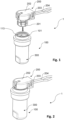
Fig. 1 discloses a connector arrangement comprising an electronic unit with a first terminal aggregate and a connector with a second terminal aggregate to be connected thereto. -
Fig. 2 discloses the connector arrangement with the first terminal aggregate connected to the connector. -
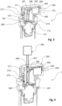
Fig. 3 discloses a cross-section of the connector arrangement ofFig. 2 before sealing. -
Fig. 4 discloses the filling of the connector arrangement ofFig. 2 with a sealing material to thereby form a sealed connector arrangement. -
Fig. 5 discloses a first cross section of the sealed connector arrangement. -
Fig. 6 discloses a second cross section of the sealed connector arrangement. -
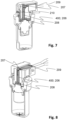
Fig. 7 discloses a first cross section of a second embodiment of a sealed connector arrangement. -
Fig. 8 discloses a second cross section of the second embodiment of a sealed connector arrangement. -
Fig. 9 is a flow-chart illustrating the different method steps. - Now turning to
Figs. 1-3 , one embodiment ofconnector arrangement 1 is disclosed. Theconnector arrangement 1 comprises anelectronic unit 100 supporting a firstterminal aggregate 101 and aconnector 200 with ahousing 202 which supports a secondterminal aggregate 201. The first and the second terminal aggregates 101, 201 are, in a condition when connected to each other, configured to form a contact with each other. The contact may, depending on the type of terminal aggregate be used to allow a power transmission or a signal transmission, such as an optical signal. - The
connector 200 comprises thehousing 202 that as such is well known in the art. Thehousing 202 provides an encapsulation of and supports a terminal aggregate. The terminal aggregate of theconnector 200 is in the present application referred to as the secondterminal aggregate 201. Further, thehousing 202 comprises acable opening 203 that is configured to receive acable 204. Thecable 204 extends into thehousing 202 from an exterior side thereof and is connected to the secondterminal aggregate 201 to allow powering thereof or to allow transmission of a signal via said secondterminal aggregate 201. Again, this is well known in the art and is not further discussed. Equally well known is the interface between thecable 204 and the secondterminal aggregate 201 which is also not disclosed. Thehousing 202 further comprises, also well known in the art, a shieldingmember 205, typically made of graphite. The skilled person realises that the housing may have numerous different designs with remained function, including the position of thecable opening 203. - According to the present invention, the
housing 202 is in its interior provided with achannel system 206. Thechannel system 206 comprises aninlet opening 207 and afirst outlet opening 208. The first outlet opening 208 is arranged adjacent the secondterminal aggregate 201. This is best seen inFig. 3 . - The disclosed
channel system 206 comprises a second outlet opening 209 which is arranged adjacent thecable opening 203. Thecable 204 is preferably arranged substantially coaxially with thecable opening 203. This means that the second outlet opening 209 will have a substantially ring-shaped cross-sectional area. As will be further discussed below, when injecting a sealing material into theinlet opening 207, the sealing material will propagate through thechannel system 206, from the inlet opening 207 to a vicinity of, or out of the second outlet opening 209, thereby sealing-off an interface between thecable 204 and thecable opening 203 of thehousing 202. By sealing-off this interface any dust or humidity is prevented from entering theconnector arrangement 100 via thecable opening 203. Since the sealing-off is made from the inside-out, an efficient sealing-off is provided for without the need for any additional/separate sealing members. Also, the sealing material contributes to the fixation of thecable 204 to thehousing 202. The sealing material hence additionally acts as a cable lock which prevents thecable 204 from being pulled out. - The disclosed
channel system 206 further comprises athird outlet opening 210. The third outlet opening 210 is arranged adjacent afree end surface 211 of thehousing 202. Thefree end surface 211 is configured to face the firstterminal aggregate 101 in a condition when theconnector 200 is connected to the firstterminal aggregate 101. The interface between thefree end surface 211 of thehousing 202 and the firstterminal aggregate 101 may be seen as agap 212 which typically has a substantially lateral extension whereas the engagement between the first and second terminal aggregates 101, 201 typically has a substantially axial extension. In the context of the invention, "axial" refers to the direction in which the first and second terminal aggregates 101, 201 are moved towards each other to form a connection therebetween. Thegap 212 may have a substantially 360 degrees circumferential extension. As will be further discussed below, when injecting a sealing material into theinlet opening 207, the sealing material will propagate through thechannel system 206, from the inlet opening 207 to a vicinity of, or out of the third outlet opening 210, thereby sealing-off the third outlet opening 210 from the inside-out and also at least a part of the interface between thefree end surface 211 of thehousing 202 and the firstterminal aggregate 101. Thereby, any dust or humidity is prevented from entering theconnector arrangement 100 via such interface and via thethird outlet opening 210. - The skilled person realizes that the
channel system 206 must not be limited to one, two or three outlet openings, but that more than three outlet openings may be applied. No matter the number of outlet openings, the cross-sectional areas of the one or more outlet opening(s) may differ depending on position. - The
channel system 206 does further preferably comprise at least onevent hole 214. The at least onevent hole 214 allows air that is entrapped in thechannel system 206 to leave the system during injection of the sealing material as will be described below. The position of the at least onevent hole 214 and the number of vent holes 214 depends on the overall design and complexity of thechannel system 206. It is preferred that the at least onevent hole 214 is arranged closer to any of the at least oneoutlet openings inlet opening 207. Also, it is preferred that the at least onevent hole 214 is smaller than any of theoutlet openings - Now turning to
Figs 1 and 2 anew. The firstterminal aggregate 101 is disclosed as being supported by and hence constituting a member of anelectrical device 300. Theelectrical device 300 may by way of example be configured to constitute a component of a road vehicle or a wearable electronic device. As a non-restricting example, theelectric device 300 may be a micro gas generator to be used in an airbag-system or in a piston-based hood lifter in a road vehicle. The firstterminal aggregate 101 may accordingly be part of such micro gas generator, piston-based hood lifter or wearable electronic device. Correspondingly, the wearable electronic device, may, as a non-limiting example be a helmet, a backpack, a vest or a hip-protection. - The first and second terminal aggregates 101, 201 may comprise
power connecting members terminal aggregate 101 may be of a male type and the secondterminal aggregate 201 of a female type. Alternatively, the firstterminal aggregate 101 may be of a female type and the secondterminal aggregate 201 of a male type. No matter type of terminal aggregate, the firstterminal aggregate 101 should be complementary to the secondterminal aggregate 201. The skilled person realizes that at least one of the twoterminal aggregates - Now turning to
Figs 4-6 , a method of producing a sealedconnector arrangement 1 of the type discussed above will be described. The individual method steps are given in the flow-chart ofFig. 9 . - The method comprises the initial steps of providing 1000 a
connector 200 and a firstterminal aggregate 101 of the type discussed above, and connecting 2000 the secondterminal aggregate 202 of theconnector 200 to the firstterminal aggregate 101 to thereby form a contact between the first and the second terminal aggregates 101, 201. - As a next step, a sealing
material 400 is injected 3000 into thechannel system 206 via theinlet opening 207. As is schematically disclosed inFig. 4 , the injection is made by anozzle 500 that is moved into fluid communication with the inlet opening 207 of thechannel system 206. Thenozzle 500 is connected to a non-disclosed dispenser. The sealingmaterial 400 is injected into the inlet opening 207 so that the sealingmaterial 400 is forced via thechannel system 206 to a vicinity of each and one of theoutlet openings channel system 206. The disclosed embodiment of thechannels system 206 comprises afirst outlet opening 208, a second outlet opening 209 and a third outlet opening 210, each of them discussed above with reference toFigs 1-3 . - When injecting the sealing
material 400 into theinlet opening 207, the sealingmaterial 400 will be forced to fill thechannel 206 and be forced to a vicinity of, or out of thefirst outlet opening 208, thereby sealing-off an interface between the first and the second terminal aggregates 101, 201. It will also be forced to a vicinity of, or out of the second outlet opening 209, thereby sealing-off an interface between thecable 204 and thecable opening 203 of thehousing 202. Further, it will be forced to a vicinity of, or out of the third outlet opening 210, thereby sealing-off an interface between thefree end surface 211 of thehousing 202 and the firstterminal aggregate 101. - The resulting filled
channel 206 is illustrated inFigs. 5 and 6 as a solid filling. As is best seen in these two figures, thechannel 206 has a three-dimensional extension inside thehousing 202 thereby forming a net-like configuration where each outlet opening is part of an individual branch. The sealingmaterial 400 will thereby seal-off and thereby prevent intrusion of humidity and dust into thehousing 202 and also into the interface between thehousing 202 and the firstterminal aggregate 101. - It is to be understood that the filling must not be made to such extent that the sealing
material 400 exits one or more of theoutlet openings material 400 reaches the vicinity of any of therespective openings channel 206 and relevant surface portions. - Further, since the second outlet opening 209 is the
cable opening 203, the sealingmaterial 400 will contribute to fixate thecable 204 to thehousing 202. This contributes to the provision of a tamper-proof sealedconnector arrangement 1 to the after-market. - The sealing
material 400 may be injected into the inlet opening 207 by using a pressure in the range of 0-8 bar, more preferred 2-8 bar and even more preferred in the range of 3-6 bar. The pressure depends on parameters such as geometry and volume of thechannel 206, any internal flow restrictions in thechannel 206, type of sealingmaterial 400, viscosity and any internal temperature differences in the parts making up theconnector arrangement 1. It is advantageous if the pressure is sufficiently high to fill thechannel 206 and also force any air that otherwise may be entrapped in the channel to leave the same. - The sealing
material 400 may be a hot melt adhesive or a two-component adhesive. It is to be understood that also other types of adhesives or sealants may be used, either alone or in combination. By way of example, thechannel system 206 may be filled, or substantially filled with a first type of sealingmaterial 400, e.g. a hot melt adhesive or a two-component adhesive, whereas any remaining space adjacent any of the one ormore outlet openings material 400. Such supplementary filling may be made from the exterior side of thehousing 202. Also, such second type of sealingmaterial 400 may be hardened by another method than the first type adhesive, such as UV heating. - Depending on the amount of sealing
material 400 that is injected, the sealingmaterial 400 may be forced all the way from the inlet opening 207 of thechannel system 206 to and out of the respective outlet opening 208, 209, 210 of thechannel system 206, i.e. providing a complete filling as is disclosed inFigs. 7 and 8 . Alternatively, the sealingmaterial 400 may be forced all the way from the inlet opening 207 of thechannel system 206 to a vicinity of the first outlet opening 208 but not out of the same as is disclosed inFigs. 5 and 6 . This may be seen as a partial filling. No matter partial or complete filling, the filling should be made to such extent that the sealingmaterial 400 seals-off the interface between the first and the second terminal aggregates 101, 201. Thus, both degrees of filling may be used on the manufacturer's choice to provide a sealedconnector arrangement 1 that is sufficiently sealed to meet a given standard. One advantage of a complete filling over a partial filling is that the complete filling better facilitates a visual quality inspection to see any pores or the like that may indicate or allow a possible leakage. - The
inlet opening 207 of thechannel system 206 will be automatically sealed-off since the sealingmaterial 400 is injected via the same. The degree of filling depends on parameters such viscosity and amount of sealingmaterial 400 injected. - The method may further comprise the act of hardening 4000 the sealing
material 400 after injecting the sealingmaterial 400 into theinlet opening 207. The hardening may be made in room temperature. The hardening may also be made by subjecting the sealedconnector arrangement 1 to an active heating, i.e. subjecting the sealedconnector arrangement 1 to a temperature above room temperature during a certain time period. The choice of hardening method, temperature and time depends on parameters such as the type of sealingmaterial 400 that is used, the volume of sealingmaterial 400 and allowed cycle time in the production system. - Accordingly, a method of producing a sealed
connector arrangement 1 is provided wherein the sealing is provided by injecting a sealingmaterial 400 into aninternal channel system 206 of thehousing 202. The injection of sealingmaterial 400 is made in a condition when theconnector 200 is connected to the firstterminal aggregate 101 thereby forming the electrical and/or optical contact between the first and the second terminal aggregates 101, 201. Accordingly, thechannel system 206 to be filled with a sealingmaterial 400 is defined partly by theconnector 200 and itshousing 202 and partly by the firstterminal aggregate 101 and hence also by the interface between the firstterminal aggregate 101 and the secondterminal aggregate 201. Thereby, theconnector 200 with itshousing 202 which supports the secondterminal aggregate 201 and which in turn is connected to the firstterminal aggregate 101 will, after filling, form one sealed aggregate in which the area surrounding the interface between the interconnected first and second terminal aggregates 101, 201 is sealed-off and hence protected from intrusion of humidity and dust. Since the first and second terminal aggregates 101, 201 are interconnected before the sealingmaterial 400 is injected, the sealing-off does not impact the communication between the twoterminal aggregates material 400 prevents dis-connection of the twoterminal aggregates - Not only does the method provide a sealed
connector arrangement 1 that may meet a set standard, but it also provides a tamper-proof unit that facilitates the process when installing a component using such sealedconnector arrangement 100 in its intended position, such as in a road vehicle or in a wearable electronic device, but it is also facilitates the after-market in the event a component using such sealedconnector arrangement 1 is provided as a spare part. Such spare part will by default be provided in a sealed condition without any separate needs to add additional sealings or gaskets. - The present method has been shown to allow manufacturing of sealed connector arrangements that meet the requirements set out in the standard IP69K which is a standard which involves a resistance to very harsh conditions in terms of humidity and dust intrusion and which standard is applied for certain components in road type vehicles.
- It is realized by a person skilled in the art that features from various embodiments disclosed herein may be combined with one another to provide further alternative embodiments.
- The
connector arrangement 100 and the method of producing the same has been described in the context of the terminal aggregates being of the plug-and-socket type for electrical power transmission. The principle is equally applicable to other types of terminal aggregates and for other types of transmission, such as optical signal transmission. Theconnector arrangement 1 may even allow parallel transmissions, such as one set of terminal aggerates arranged for electrical power transmission and one set of terminal aggregates arranged for optical signal transmission. Such parallel terminal aggregates may be contained in one and the same branch of the channel system and hence be arranged in the vicinity of one and the same outlet opening. It is also understood that the parallel terminal aggregates may be contained in different branches of the channel system and hence be arranged in the vicinity of different outlet openings. - The connector arrangement has been descried as comprising a housing with one single channel system, said channel system comprising one inlet opening and three outlet openings. The skilled person realises that the design of the housing with its channel system, the spatial extension of the channel system inside the housing and the number of outlets may vary within the scope of the invention. Non-limiting examples of decisive factors are the type of terminal aggregates, the overall design of the housing, the type of electrical device and the position of the cable opening. Accordingly, the disclosed embodiment is only one non-limiting example.
- Also, the skilled person realizes that a plurality of discrete channels may be used, where each channel comprises one inlet opening and one or more outlet openings.
Claims (13)
- A method of producing a sealed connector arrangement, by means of a first terminal aggregate (101) and a connector (200),the first terminal aggregate (101) being adapted to form part of an electronic unit; andthe connector (200) comprising:a housing (202) supporting a second terminal aggregate (201) adapted to form an electrical and/or optical contact with the first terminal aggregate (101);a cable (204) connected to the second terminal aggregate (201) and extending out of the housing (202) through a cable opening (203); anda channel system (206) comprising an inlet opening (207) and a first outlet opening (208), said first outlet opening (208) being arranged adjacentthe second terminal aggregate (201); the method comprising:connecting the connector (200) to the first terminal aggregate (101) thereby forming the electrical and/or optical contact between the first and the second terminal aggregates (101, 201);injecting a sealing material (400) into the inlet opening (207) so that the sealing material (400) is forced via the channel system (206) to a vicinity of, or out of the first outlet opening (208), thereby sealing off an interface between the first and the second terminal aggregates (101, 201).
- The method of claim 1, wherein the channel system (206) further comprises a second outlet opening (209) being arranged adjacent the cable opening (203), wherein the act of injecting sealing material (400) into the inlet opening (207) further comprises forcing the sealing material (400) via the channel system (206) to a vicinity of, or out of the second outlet opening (209), thereby sealing off an interface between the cable (204) and the cable opening (203) of the housing (202).
- The method of claim 1, wherein the channel system (206) further comprises a third outlet opening (210) being arranged adjacent a free surface of the housing (202) configured to face the first terminal aggregate (101) in a condition when the connector (200) is connected to the first terminal aggregate (101), wherein the act of injecting sealing material (400) into the inlet opening (207) further comprises forcing the sealing material (400) via the channel system (206) to a vicinity of, or out of the third outlet opening (210), thereby sealing off an interface between the free surface of the housing (202) and the first terminal aggregate (101).
- The method according to any of the preceding claims, wherein the sealing material (400) is injected into the inlet opening (207) by using a pressure in the range of 0-8 bar, more preferred in the range of 2-8 bar and even more preferred in the range of 3-6 bar.
- The method according to any of the preceding claims, further comprising the act of hardening the sealing material (400) after injecting the sealing material (400) into the inlet opening (207).
- The method according to any of claims 1-5, wherein the sealing material (400) is a hot melt adhesive or a two-component adhesive.
- The method according to any of claims 1-6, wherein the channel system (206) further comprises at least one vent hole (214), whereby air in the channel system (206) is allowed to leave the channel system (206) during the act of injecting the sealing material (400).
- A sealed connector arrangement, the connector arrangement (100) being manufactured by using the method according to any of claims 1-7.
- The sealed connector arrangement according to claim 8, wherein the first terminal aggregate (101) is an electric device or a member of an electric device.
- The sealed connector arrangement according to claim 9, wherein the electrical device is configured to form part of a road vehicle or a wearable electronic device.
- The sealed connector arrangement according to claim 9, wherein the first terminal arrangement (101) is part of a micro gas generator.
- The sealed connector arrangement according to any of claims 8-11, wherein the first and second terminal aggregates (101, 201) comprise power connecting members or optical connecting members.
- Use of the method according to any of claims 1-7 to produce a sealed connector arrangement (100) to be used in a road vehicle or in a wearable electronic device.
Priority Applications (1)
| Application Number | Priority Date | Filing Date | Title |
|---|---|---|---|
| EP21207760.6A EP4181330B1 (en) | 2021-11-11 | 2021-11-11 | A method of producing a sealed connector arrangement, a sealed connector arrangement and use of the method |
Applications Claiming Priority (1)
| Application Number | Priority Date | Filing Date | Title |
|---|---|---|---|
| EP21207760.6A EP4181330B1 (en) | 2021-11-11 | 2021-11-11 | A method of producing a sealed connector arrangement, a sealed connector arrangement and use of the method |
Publications (2)
| Publication Number | Publication Date |
|---|---|
| EP4181330A1 true EP4181330A1 (en) | 2023-05-17 |
| EP4181330B1 EP4181330B1 (en) | 2025-10-08 |
Family
ID=78598938
Family Applications (1)
| Application Number | Title | Priority Date | Filing Date |
|---|---|---|---|
| EP21207760.6A Active EP4181330B1 (en) | 2021-11-11 | 2021-11-11 | A method of producing a sealed connector arrangement, a sealed connector arrangement and use of the method |
Country Status (1)
| Country | Link |
|---|---|
| EP (1) | EP4181330B1 (en) |
Citations (2)
| Publication number | Priority date | Publication date | Assignee | Title |
|---|---|---|---|---|
| US5278357A (en) * | 1991-02-14 | 1994-01-11 | Yazaki Corporation | Electric wire holding case preventing of oil leak |
| US20100055953A1 (en) * | 2008-09-04 | 2010-03-04 | Tyco Electronics Corporation | Connector assembly having a plurality of discrete components |
-
2021
- 2021-11-11 EP EP21207760.6A patent/EP4181330B1/en active Active
Patent Citations (2)
| Publication number | Priority date | Publication date | Assignee | Title |
|---|---|---|---|---|
| US5278357A (en) * | 1991-02-14 | 1994-01-11 | Yazaki Corporation | Electric wire holding case preventing of oil leak |
| US20100055953A1 (en) * | 2008-09-04 | 2010-03-04 | Tyco Electronics Corporation | Connector assembly having a plurality of discrete components |
Also Published As
| Publication number | Publication date |
|---|---|
| EP4181330B1 (en) | 2025-10-08 |
Similar Documents
| Publication | Publication Date | Title |
|---|---|---|
| EP1204173B1 (en) | Waterproof structure in cable insertion section, method of manufacturing the same, and die for waterproof molding | |
| EP2916394B1 (en) | Connector | |
| KR101573967B1 (en) | Sealed electrical connector | |
| US8734174B2 (en) | Waterproof connector having an integrally formed elastic seal member | |
| CN104704688B (en) | Module system for a charging apparatus, charging apparatus and vehicle comprising a charging apparatus constructed from the module system | |
| US11616267B2 (en) | Modular system for traction batteries of motor vehicles | |
| WO2009139220A1 (en) | Water stop structure for wire harness | |
| CN101495783A (en) | Control unit for automatic transmission and automatic transmission with control unit | |
| US6341983B1 (en) | Co-molded seal and strain relief for automotive electrical connections | |
| JP3449865B2 (en) | Wiring connector for automatic transmission | |
| JP2859822B2 (en) | Structure for airtight test of electrical equipment | |
| EP3490077B1 (en) | Sealed electrical wire harness and manufacturing method thereof | |
| US20090149085A1 (en) | Socket and Method for its Production | |
| CN101710662B (en) | Connector assembly with plurality of discrete components | |
| JP5602857B2 (en) | Connection component for an electrical conductor and method for coating the connection component | |
| JP2011181451A (en) | Joint connector | |
| CN108430180A (en) | Method for the electronic module of industrial automation and for manufacturing the electronic module | |
| US7061146B2 (en) | Drive arrangement with a fixed bearing | |
| EP4181330B1 (en) | A method of producing a sealed connector arrangement, a sealed connector arrangement and use of the method | |
| JP5157632B2 (en) | Connection structure of electronic control unit and wire harness | |
| KR20190089169A (en) | Electrical assembly | |
| EP3669622A1 (en) | Aperture seal structure | |
| JP4074392B2 (en) | Electrical cable connection element | |
| WO2019170558A1 (en) | Sealing unit for a conductor and electrical connector | |
| US12155145B2 (en) | Method for producing an electrical connector, in particular an electrical connector for a high-density header system; as well as an electrical connector, in particular an electrical connector for the motor vehicle industry; as well as high-density header system |
Legal Events
| Date | Code | Title | Description |
|---|---|---|---|
| PUAI | Public reference made under article 153(3) epc to a published international application that has entered the european phase |
Free format text: ORIGINAL CODE: 0009012 |
|
| STAA | Information on the status of an ep patent application or granted ep patent |
Free format text: STATUS: THE APPLICATION HAS BEEN PUBLISHED |
|
| AK | Designated contracting states |
Kind code of ref document: A1 Designated state(s): AL AT BE BG CH CY CZ DE DK EE ES FI FR GB GR HR HU IE IS IT LI LT LU LV MC MK MT NL NO PL PT RO RS SE SI SK SM TR |
|
| STAA | Information on the status of an ep patent application or granted ep patent |
Free format text: STATUS: REQUEST FOR EXAMINATION WAS MADE |
|
| 17P | Request for examination filed |
Effective date: 20230901 |
|
| RBV | Designated contracting states (corrected) |
Designated state(s): AL AT BE BG CH CY CZ DE DK EE ES FI FR GB GR HR HU IE IS IT LI LT LU LV MC MK MT NL NO PL PT RO RS SE SI SK SM TR |
|
| GRAP | Despatch of communication of intention to grant a patent |
Free format text: ORIGINAL CODE: EPIDOSNIGR1 |
|
| STAA | Information on the status of an ep patent application or granted ep patent |
Free format text: STATUS: GRANT OF PATENT IS INTENDED |
|
| INTG | Intention to grant announced |
Effective date: 20250523 |
|
| GRAS | Grant fee paid |
Free format text: ORIGINAL CODE: EPIDOSNIGR3 |
|
| GRAA | (expected) grant |
Free format text: ORIGINAL CODE: 0009210 |
|
| STAA | Information on the status of an ep patent application or granted ep patent |
Free format text: STATUS: THE PATENT HAS BEEN GRANTED |
|
| AK | Designated contracting states |
Kind code of ref document: B1 Designated state(s): AL AT BE BG CH CY CZ DE DK EE ES FI FR GB GR HR HU IE IS IT LI LT LU LV MC MK MT NL NO PL PT RO RS SE SI SK SM TR |
|
| RAP3 | Party data changed (applicant data changed or rights of an application transferred) |
Owner name: AUTOLIV DEVELOPMENT AB |
|
| REG | Reference to a national code |
Ref country code: GB Ref legal event code: FG4D Ref country code: CH Ref legal event code: F10 Free format text: ST27 STATUS EVENT CODE: U-0-0-F10-F00 (AS PROVIDED BY THE NATIONAL OFFICE) Effective date: 20251008 |
|
| REG | Reference to a national code |
Ref country code: DE Ref legal event code: R096 Ref document number: 602021039977 Country of ref document: DE |
|
| REG | Reference to a national code |
Ref country code: IE Ref legal event code: FG4D |
|
| PGFP | Annual fee paid to national office [announced via postgrant information from national office to epo] |
Ref country code: DE Payment date: 20251126 Year of fee payment: 5 |
|
| PGFP | Annual fee paid to national office [announced via postgrant information from national office to epo] |
Ref country code: GB Payment date: 20251125 Year of fee payment: 5 |
|
| PGFP | Annual fee paid to national office [announced via postgrant information from national office to epo] |
Ref country code: AT Payment date: 20260113 Year of fee payment: 5 |
|
| PGFP | Annual fee paid to national office [announced via postgrant information from national office to epo] |
Ref country code: FR Payment date: 20251124 Year of fee payment: 5 |
|
| REG | Reference to a national code |
Ref country code: NL Ref legal event code: MP Effective date: 20251008 |
|
| REG | Reference to a national code |
Ref country code: AT Ref legal event code: MK05 Ref document number: 1845677 Country of ref document: AT Kind code of ref document: T Effective date: 20251008 |
|
| PG25 | Lapsed in a contracting state [announced via postgrant information from national office to epo] |
Ref country code: NL Free format text: LAPSE BECAUSE OF FAILURE TO SUBMIT A TRANSLATION OF THE DESCRIPTION OR TO PAY THE FEE WITHIN THE PRESCRIBED TIME-LIMIT Effective date: 20251008 |
|
| PG25 | Lapsed in a contracting state [announced via postgrant information from national office to epo] |
Ref country code: ES Free format text: LAPSE BECAUSE OF FAILURE TO SUBMIT A TRANSLATION OF THE DESCRIPTION OR TO PAY THE FEE WITHIN THE PRESCRIBED TIME-LIMIT Effective date: 20251008 |
|
| REG | Reference to a national code |
Ref country code: LT Ref legal event code: MG9D |
|
| PG25 | Lapsed in a contracting state [announced via postgrant information from national office to epo] |
Ref country code: NO Free format text: LAPSE BECAUSE OF FAILURE TO SUBMIT A TRANSLATION OF THE DESCRIPTION OR TO PAY THE FEE WITHIN THE PRESCRIBED TIME-LIMIT Effective date: 20260108 |
|
| PG25 | Lapsed in a contracting state [announced via postgrant information from national office to epo] |
Ref country code: HR Free format text: LAPSE BECAUSE OF FAILURE TO SUBMIT A TRANSLATION OF THE DESCRIPTION OR TO PAY THE FEE WITHIN THE PRESCRIBED TIME-LIMIT Effective date: 20251008 Ref country code: AT Free format text: LAPSE BECAUSE OF FAILURE TO SUBMIT A TRANSLATION OF THE DESCRIPTION OR TO PAY THE FEE WITHIN THE PRESCRIBED TIME-LIMIT Effective date: 20251008 Ref country code: FI Free format text: LAPSE BECAUSE OF FAILURE TO SUBMIT A TRANSLATION OF THE DESCRIPTION OR TO PAY THE FEE WITHIN THE PRESCRIBED TIME-LIMIT Effective date: 20251008 |
|
| PG25 | Lapsed in a contracting state [announced via postgrant information from national office to epo] |
Ref country code: RS Free format text: LAPSE BECAUSE OF FAILURE TO SUBMIT A TRANSLATION OF THE DESCRIPTION OR TO PAY THE FEE WITHIN THE PRESCRIBED TIME-LIMIT Effective date: 20260108 |
|
| PG25 | Lapsed in a contracting state [announced via postgrant information from national office to epo] |
Ref country code: IS Free format text: LAPSE BECAUSE OF FAILURE TO SUBMIT A TRANSLATION OF THE DESCRIPTION OR TO PAY THE FEE WITHIN THE PRESCRIBED TIME-LIMIT Effective date: 20260208 |
|
| PG25 | Lapsed in a contracting state [announced via postgrant information from national office to epo] |
Ref country code: PT Free format text: LAPSE BECAUSE OF FAILURE TO SUBMIT A TRANSLATION OF THE DESCRIPTION OR TO PAY THE FEE WITHIN THE PRESCRIBED TIME-LIMIT Effective date: 20260209 |
|
| PG25 | Lapsed in a contracting state [announced via postgrant information from national office to epo] |
Ref country code: PL Free format text: LAPSE BECAUSE OF FAILURE TO SUBMIT A TRANSLATION OF THE DESCRIPTION OR TO PAY THE FEE WITHIN THE PRESCRIBED TIME-LIMIT Effective date: 20251008 |
|
| PG25 | Lapsed in a contracting state [announced via postgrant information from national office to epo] |
Ref country code: LV Free format text: LAPSE BECAUSE OF FAILURE TO SUBMIT A TRANSLATION OF THE DESCRIPTION OR TO PAY THE FEE WITHIN THE PRESCRIBED TIME-LIMIT Effective date: 20251008 |
|
| PG25 | Lapsed in a contracting state [announced via postgrant information from national office to epo] |
Ref country code: BG Free format text: LAPSE BECAUSE OF FAILURE TO SUBMIT A TRANSLATION OF THE DESCRIPTION OR TO PAY THE FEE WITHIN THE PRESCRIBED TIME-LIMIT Effective date: 20251008 |
|
| PG25 | Lapsed in a contracting state [announced via postgrant information from national office to epo] |
Ref country code: RO Free format text: LAPSE BECAUSE OF FAILURE TO SUBMIT A TRANSLATION OF THE DESCRIPTION OR TO PAY THE FEE WITHIN THE PRESCRIBED TIME-LIMIT Effective date: 20251008 |
|
| REG | Reference to a national code |
Ref country code: CH Ref legal event code: H13 Free format text: ST27 STATUS EVENT CODE: U-0-0-H10-H13 (AS PROVIDED BY THE NATIONAL OFFICE) Effective date: 20260623 |
|
| PG25 | Lapsed in a contracting state [announced via postgrant information from national office to epo] |
Ref country code: LT Free format text: LAPSE BECAUSE OF FAILURE TO SUBMIT A TRANSLATION OF THE DESCRIPTION OR TO PAY THE FEE WITHIN THE PRESCRIBED TIME-LIMIT Effective date: 20251008 |
|
| PG25 | Lapsed in a contracting state [announced via postgrant information from national office to epo] |
Ref country code: SM Free format text: LAPSE BECAUSE OF FAILURE TO SUBMIT A TRANSLATION OF THE DESCRIPTION OR TO PAY THE FEE WITHIN THE PRESCRIBED TIME-LIMIT Effective date: 20251008 |
|
| PG25 | Lapsed in a contracting state [announced via postgrant information from national office to epo] |
Ref country code: MC Free format text: LAPSE BECAUSE OF FAILURE TO SUBMIT A TRANSLATION OF THE DESCRIPTION OR TO PAY THE FEE WITHIN THE PRESCRIBED TIME-LIMIT Effective date: 20251008 |
|
| PG25 | Lapsed in a contracting state [announced via postgrant information from national office to epo] |
Ref country code: DK Free format text: LAPSE BECAUSE OF FAILURE TO SUBMIT A TRANSLATION OF THE DESCRIPTION OR TO PAY THE FEE WITHIN THE PRESCRIBED TIME-LIMIT Effective date: 20251008 |
|
| PG25 | Lapsed in a contracting state [announced via postgrant information from national office to epo] |
Ref country code: IT Free format text: LAPSE BECAUSE OF FAILURE TO SUBMIT A TRANSLATION OF THE DESCRIPTION OR TO PAY THE FEE WITHIN THE PRESCRIBED TIME-LIMIT Effective date: 20251008 |
|
| PG25 | Lapsed in a contracting state [announced via postgrant information from national office to epo] |
Ref country code: LU Free format text: LAPSE BECAUSE OF NON-PAYMENT OF DUE FEES Effective date: 20251111 Ref country code: CH Free format text: LAPSE BECAUSE OF NON-PAYMENT OF DUE FEES Effective date: 20251130 |
|
| PG25 | Lapsed in a contracting state [announced via postgrant information from national office to epo] |
Ref country code: EE Free format text: LAPSE BECAUSE OF FAILURE TO SUBMIT A TRANSLATION OF THE DESCRIPTION OR TO PAY THE FEE WITHIN THE PRESCRIBED TIME-LIMIT Effective date: 20251008 |
|
| PG25 | Lapsed in a contracting state [announced via postgrant information from national office to epo] |
Ref country code: CZ Free format text: LAPSE BECAUSE OF FAILURE TO SUBMIT A TRANSLATION OF THE DESCRIPTION OR TO PAY THE FEE WITHIN THE PRESCRIBED TIME-LIMIT Effective date: 20251008 |
|
| PG25 | Lapsed in a contracting state [announced via postgrant information from national office to epo] |
Ref country code: SK Free format text: LAPSE BECAUSE OF FAILURE TO SUBMIT A TRANSLATION OF THE DESCRIPTION OR TO PAY THE FEE WITHIN THE PRESCRIBED TIME-LIMIT Effective date: 20251008 |
|
| PG25 | Lapsed in a contracting state [announced via postgrant information from national office to epo] |
Ref country code: SE Free format text: LAPSE BECAUSE OF FAILURE TO SUBMIT A TRANSLATION OF THE DESCRIPTION OR TO PAY THE FEE WITHIN THE PRESCRIBED TIME-LIMIT Effective date: 20251008 |
|
| PLBE | No opposition filed within time limit |
Free format text: ORIGINAL CODE: 0009261 |
|
| STAA | Information on the status of an ep patent application or granted ep patent |
Free format text: STATUS: NO OPPOSITION FILED WITHIN TIME LIMIT |