EP4181325A1 - Connector device - Google Patents
Connector device Download PDFInfo
- Publication number
- EP4181325A1 EP4181325A1 EP21864554.7A EP21864554A EP4181325A1 EP 4181325 A1 EP4181325 A1 EP 4181325A1 EP 21864554 A EP21864554 A EP 21864554A EP 4181325 A1 EP4181325 A1 EP 4181325A1
- Authority
- EP
- European Patent Office
- Prior art keywords
- connector
- gear
- ratchet
- ratchet gear
- stopper
- Prior art date
- Legal status (The legal status is an assumption and is not a legal conclusion. Google has not performed a legal analysis and makes no representation as to the accuracy of the status listed.)
- Granted
Links
Images



Classifications
-
- H—ELECTRICITY
- H01—ELECTRIC ELEMENTS
- H01R—ELECTRICALLY-CONDUCTIVE CONNECTIONS; STRUCTURAL ASSOCIATIONS OF A PLURALITY OF MUTUALLY-INSULATED ELECTRICAL CONNECTING ELEMENTS; COUPLING DEVICES; CURRENT COLLECTORS
- H01R12/00—Structural associations of a plurality of mutually-insulated electrical connecting elements, specially adapted for printed circuits, e.g. printed circuit boards [PCB], flat or ribbon cables, or like generally planar structures, e.g. terminal strips, terminal blocks; Coupling devices specially adapted for printed circuits, flat or ribbon cables, or like generally planar structures; Terminals specially adapted for contact with, or insertion into, printed circuits, flat or ribbon cables, or like generally planar structures
- H01R12/70—Coupling devices
- H01R12/71—Coupling devices for rigid printing circuits or like structures
- H01R12/712—Coupling devices for rigid printing circuits or like structures co-operating with the surface of the printed circuit or with a coupling device exclusively provided on the surface of the printed circuit
- H01R12/716—Coupling device provided on the PCB
-
- H—ELECTRICITY
- H01—ELECTRIC ELEMENTS
- H01R—ELECTRICALLY-CONDUCTIVE CONNECTIONS; STRUCTURAL ASSOCIATIONS OF A PLURALITY OF MUTUALLY-INSULATED ELECTRICAL CONNECTING ELEMENTS; COUPLING DEVICES; CURRENT COLLECTORS
- H01R12/00—Structural associations of a plurality of mutually-insulated electrical connecting elements, specially adapted for printed circuits, e.g. printed circuit boards [PCB], flat or ribbon cables, or like generally planar structures, e.g. terminal strips, terminal blocks; Coupling devices specially adapted for printed circuits, flat or ribbon cables, or like generally planar structures; Terminals specially adapted for contact with, or insertion into, printed circuits, flat or ribbon cables, or like generally planar structures
- H01R12/70—Coupling devices
- H01R12/7005—Guiding, mounting, polarizing or locking means; Extractors
-
- H—ELECTRICITY
- H01—ELECTRIC ELEMENTS
- H01R—ELECTRICALLY-CONDUCTIVE CONNECTIONS; STRUCTURAL ASSOCIATIONS OF A PLURALITY OF MUTUALLY-INSULATED ELECTRICAL CONNECTING ELEMENTS; COUPLING DEVICES; CURRENT COLLECTORS
- H01R13/00—Details of coupling devices of the kinds covered by groups H01R12/70 or H01R24/00 - H01R33/00
- H01R13/62—Means for facilitating engagement or disengagement of coupling parts or for holding them in engagement
- H01R13/627—Snap or like fastening
- H01R13/6271—Latching means integral with the housing
-
- F—MECHANICAL ENGINEERING; LIGHTING; HEATING; WEAPONS; BLASTING
- F16—ENGINEERING ELEMENTS AND UNITS; GENERAL MEASURES FOR PRODUCING AND MAINTAINING EFFECTIVE FUNCTIONING OF MACHINES OR INSTALLATIONS; THERMAL INSULATION IN GENERAL
- F16H—GEARING
- F16H19/00—Gearings comprising essentially only toothed gears or friction members and not capable of conveying indefinitely-continuing rotary motion
- F16H19/02—Gearings comprising essentially only toothed gears or friction members and not capable of conveying indefinitely-continuing rotary motion for interconverting rotary or oscillating motion and reciprocating motion
- F16H19/04—Gearings comprising essentially only toothed gears or friction members and not capable of conveying indefinitely-continuing rotary motion for interconverting rotary or oscillating motion and reciprocating motion comprising a rack
-
- H—ELECTRICITY
- H01—ELECTRIC ELEMENTS
- H01R—ELECTRICALLY-CONDUCTIVE CONNECTIONS; STRUCTURAL ASSOCIATIONS OF A PLURALITY OF MUTUALLY-INSULATED ELECTRICAL CONNECTING ELEMENTS; COUPLING DEVICES; CURRENT COLLECTORS
- H01R12/00—Structural associations of a plurality of mutually-insulated electrical connecting elements, specially adapted for printed circuits, e.g. printed circuit boards [PCB], flat or ribbon cables, or like generally planar structures, e.g. terminal strips, terminal blocks; Coupling devices specially adapted for printed circuits, flat or ribbon cables, or like generally planar structures; Terminals specially adapted for contact with, or insertion into, printed circuits, flat or ribbon cables, or like generally planar structures
- H01R12/70—Coupling devices
- H01R12/71—Coupling devices for rigid printing circuits or like structures
- H01R12/75—Coupling devices for rigid printing circuits or like structures connecting to cables except for flat or ribbon cables
-
- H—ELECTRICITY
- H01—ELECTRIC ELEMENTS
- H01R—ELECTRICALLY-CONDUCTIVE CONNECTIONS; STRUCTURAL ASSOCIATIONS OF A PLURALITY OF MUTUALLY-INSULATED ELECTRICAL CONNECTING ELEMENTS; COUPLING DEVICES; CURRENT COLLECTORS
- H01R13/00—Details of coupling devices of the kinds covered by groups H01R12/70 or H01R24/00 - H01R33/00
- H01R13/62—Means for facilitating engagement or disengagement of coupling parts or for holding them in engagement
- H01R13/639—Additional means for holding or locking coupling parts together, after engagement, e.g. separate keylock, retainer strap
-
- H—ELECTRICITY
- H01—ELECTRIC ELEMENTS
- H01R—ELECTRICALLY-CONDUCTIVE CONNECTIONS; STRUCTURAL ASSOCIATIONS OF A PLURALITY OF MUTUALLY-INSULATED ELECTRICAL CONNECTING ELEMENTS; COUPLING DEVICES; CURRENT COLLECTORS
- H01R24/00—Two-part coupling devices, or either of their cooperating parts, characterised by their overall structure
- H01R24/60—Contacts spaced along planar side wall transverse to longitudinal axis of engagement
-
- F—MECHANICAL ENGINEERING; LIGHTING; HEATING; WEAPONS; BLASTING
- F16—ENGINEERING ELEMENTS AND UNITS; GENERAL MEASURES FOR PRODUCING AND MAINTAINING EFFECTIVE FUNCTIONING OF MACHINES OR INSTALLATIONS; THERMAL INSULATION IN GENERAL
- F16H—GEARING
- F16H19/00—Gearings comprising essentially only toothed gears or friction members and not capable of conveying indefinitely-continuing rotary motion
- F16H19/02—Gearings comprising essentially only toothed gears or friction members and not capable of conveying indefinitely-continuing rotary motion for interconverting rotary or oscillating motion and reciprocating motion
- F16H19/04—Gearings comprising essentially only toothed gears or friction members and not capable of conveying indefinitely-continuing rotary motion for interconverting rotary or oscillating motion and reciprocating motion comprising a rack
- F16H2019/046—Facilitating the engagement or stopping of racks
-
- H—ELECTRICITY
- H01—ELECTRIC ELEMENTS
- H01R—ELECTRICALLY-CONDUCTIVE CONNECTIONS; STRUCTURAL ASSOCIATIONS OF A PLURALITY OF MUTUALLY-INSULATED ELECTRICAL CONNECTING ELEMENTS; COUPLING DEVICES; CURRENT COLLECTORS
- H01R13/00—Details of coupling devices of the kinds covered by groups H01R12/70 or H01R24/00 - H01R33/00
- H01R13/62—Means for facilitating engagement or disengagement of coupling parts or for holding them in engagement
- H01R13/629—Additional means for facilitating engagement or disengagement of coupling parts, e.g. aligning or guiding means, levers, gas pressure electrical locking indicators, manufacturing tolerances
- H01R13/62905—Additional means for facilitating engagement or disengagement of coupling parts, e.g. aligning or guiding means, levers, gas pressure electrical locking indicators, manufacturing tolerances comprising a camming member
-
- H—ELECTRICITY
- H01—ELECTRIC ELEMENTS
- H01R—ELECTRICALLY-CONDUCTIVE CONNECTIONS; STRUCTURAL ASSOCIATIONS OF A PLURALITY OF MUTUALLY-INSULATED ELECTRICAL CONNECTING ELEMENTS; COUPLING DEVICES; CURRENT COLLECTORS
- H01R2107/00—Four or more poles
Definitions
- the present invention relates to a connector device in which the coupling between a first connector provided with a terminal and a second connector provided with a socket is enhanced.
- connector devices are to connect electric wires and devices such as vehicles or home appliances, which use electricity, in a manner so as to conduct electricity or to separate the same, and comprise a first connector which is provided on a substrate of a device and a second connector which is coupled to the first connector and to which an electric wire is connected.
- the first connector and the second connector are coupled by a locking groove and a locking part.
- the first connector and the second connector are not conveniently separated.
- the first connector and the second connector are simply coupled without the locking groove and the locking part, they are very easily separated.
- An object of the present invention is to provide a connector device which utilizes a ratchet gear and may couple a first connector and a second connector so as not to be easily separated or uncouple the first connector and the second connector so as to be conveniently separable.
- a connector device of the present invention comprises: a first connector which is fastened to a substrate, and comprises a terminal body having an opening provided in one surface thereof and a terminal provided in the opening and electrically connected to the substrate; a second connector which is fastened to an electric wire, and comprises a socket body inserted into the opening of the terminal body and a socket provided inside the socket body and contacting the terminal; and a ratchet part by which the first connector and the second connector are coupled so as not to be separated or uncoupled so as to be separable.
- the ratchet part may comprise: a toothed gear which is provided on an outer surface of the socket body and has teeth provided in a direction toward the terminal body when the socket body is inserted into the terminal body; a ratchet gear which is provided in the terminal body and engages with the toothed gear, and couples the first connector and the second connector so as not to be separated when fixed and uncouples the first connector and the second connector so as to be separable when rotating; and a stopper by which the ratchet gear is fixed so as not to rotate or unfixed so as to be rotatable.
- the ratchet gear may be allowed to rotate only in a direction in which the second connector and the first connector are coupled.
- the ratchet part may further comprise a spring that provides an elastic force to maintain a state in which the stopper is inserted into a groove between gear teeth of the ratchet gear.
- the ratchet gear When the first connector and the second connector are coupled, the ratchet gear may be rotated by the toothed gear in a direction in which the first connector and the second connector are coupled.
- the ratchet gear may rotate while pushing the front end of the stopper outward from the groove between the gear teeth of the ratchet gear and thus may rotate without interference by the stopper, and the stopper may continuously move from a groove to another groove between the gear teeth of the ratchet gear while being pulled in a direction toward the ratchet gear by the elastic force of the spring.
- the ratchet gear When the first connector and the second connector are separated in a state in which the stopper is inserted into the groove between the gear teeth of the ratchet gear, the ratchet gear may be rotated by the toothed gear in a direction in which the first connector and the second connector are separated.
- the ratchet gear may press the front end of the stopper inward from the groove between the gear teeth of the ratchet gear and thus may not rotate because the front end of the stopper does not escape from the groove between the gear teeth of the ratchet gear, and as the toothed gear is not moved by the ratchet gear, the first connector and the second connector may not be separated.
- the ratchet gear When the first connector and the second connector are separated in a state in which the stopper escapes from the groove between the gear teeth of the ratchet gear, the ratchet gear may continuously rotate because the stopper escapes from the groove between the gear teeth of the ratchet gear, and as the toothed gear is moved by rotation of the ratchet gear, the first connector and the second connector may be separated.
- the ratchet part may further comprise a ratchet body which is detachably coupled to the terminal body and on which the ratchet gear, the stopper, and the spring are installed.
- a guide groove may be formed inside the terminal body, and a guide protrusion guided along the guide groove may be formed in the socket body.
- a locking groove connected to the guide groove may be formed in one surface of the terminal body in which the guide groove is formed, and a locking protrusion locked and supported by the locking groove may be formed in the guide protrusion.
- the toothed gear may be detachably installed on the socket body.
- the first connector may further comprise a protection cover that protects the ratchet gear and the stopper provided in the terminal body.
- One end of the protection cover may be rotatably coupled to the terminal body.
- the stopper may comprise a guide piece, which is installed on an outer circumferential surface of the terminal body and is slidable in a direction toward the ratchet gear, and a fixing piece, which is inserted into a groove between gear teeth of the ratchet gear and fixes the ratchet gear so as not to rotate.
- the connector device of the present invention comprises the first connector, the second connector, and the ratchet part, and the ratchet part comprises the toothed gear, the ratchet gear, and the stopper. Due to this feature, the first connector and the second connector may be coupled so as not to be separated or may be uncoupled so as to be conveniently separable. As a result, the safety and convenience may be enhanced.
- the ratchet gear is allowed to rotate only in the direction in which the second connector and the first connector are coupled. Due to this feature, the first connector and the second connector may be separated only when the stopper is separated from the ratchet gear. Accordingly, it is possible to prevent an accident in which the first and second connectors are easily separated by an external force.
- a connector device having a structure for connecting a substrate and an electric wire is described as one embodiment.
- a connector device for connecting an electronic device to an electronic device and an electric wire to an electric wire may also be applied in the same manner.
- the connector device according to the first embodiment of the present invention may have a coupling structure using a ratchet as illustrated in FIGS. 1 to 5 . That is, the connector device according to the first embodiment of the present invention comprises a first connector 100, a second connector 200, and a ratchet part 300 which couples or separably uncouples the first connector 100 and the second connector.
- the first connector 100 is fastened to a substrate 10, and comprises a terminal body 110 having an opening 100a provided in one surface thereof and a terminal 120 provided in the opening 100a and electrically connected to the substrate 10.
- the second connector 200 is fastened to an electric wire 20, and comprises a socket body 210 inserted into the opening 100a of the terminal body 110 and a socket 220 provided inside the socket body 210 and contacting the terminal 120.
- the ratchet part 300 couples the first connector and the second connector so as not to be separated or uncouples the same so as to be conveniently separable, and comprises a toothed gear 310, a ratchet gear 320, a stopper 330, and a spring 340.
- the toothed gear 310 is provided on the outer surface (the outer surface on the outside of the socket body when viewed in FIG. 3 ) of the socket body 210 and comprises a plurality of teeth.
- the teeth are provided in a direction (the up-down direction when viewed in FIG. 3 ) toward the terminal body 110 when the socket body 210 is inserted into the terminal body 110, and a plurality of teeth are provided at certain intervals.
- the ratchet gear 320 is freely rotatably provided in the terminal body 110 and engages with the toothed gear 310 when the first connector 100 and the second connector 200 are coupled, and couples the first connector 100 and the second connector 200 so as not to be separated when fixed and uncouples the first connector 100 and the second connector 200 so as to be separable when rotating.
- the first connector 100 and the second connector 200 may be coupled or separated as the toothed gear 310 engaging with the ratchet gear 320 moves. Also, when the ratchet gear 320 is fixed, the first connector 100 and the second connector 200 may be fixed in a coupled state as the toothed gear 310 engaging with the ratchet gear 320 does not move.
- the ratchet gear 320 has, on the outer circumferential surface, a plurality of gear teeth 321 and grooves 322 between the gear teeth 321.
- a surface, which faces a direction in which the second connector 200 is coupled to the first connector 100, (a right side surface of the gear tooth when viewed in FIG. 4 ) is formed as a vertical surface 321b, and a surface, which faces a direction in which the second connector 200 is separated from the first connector 100, (a left side surface of the gear tooth when viewed in FIG. 4 ) is formed as an inclined surface 321a.
- the ratchet gear 320 may rotate in the direction in which the second connector 200 is coupled to the first connector 100. Also, referring to FIG. 5 , as the stopper is locked to the vertical surface 321b, the ratchet gear 320 may not rotate in the direction in which the second connector 200 is separated from the first connector 100.
- the stopper 330 has a structure by which the ratchet gear 320 is fixed so as not to rotate or unfixed so as to be rotatable. That is, as a front end of the stopper 330 is inserted into a groove 322 between gear teeth 321 of the ratchet gear 320, the ratchet gear 320 is allowed to rotate only in a direction in which the second connector 200 and the first connector 100 are coupled. Accordingly, without removing the stopper 330, the second connector 200 and the first connector 100 may be coupled, but the second connector 200 and the first connector 100 may not be uncoupled.
- the stopper 330 is guided along the inclined surface 321a provided in the gear tooth 321 of the ratchet gear 320 and continuously moves from a groove to another groove of the ratchet gear 320. Accordingly, the first connector 100 and the second connector 200 may be coupled even without removing the front end of the stopper 330 inserted into the ratchet gear 320.
- the stopper 330 is locked to the vertical surface 321b provided in the gear tooth 321 of the ratchet gear 320 and prevents the rotation of the ratchet gear 320. Accordingly, the first connector 100 and the second connector 200 may be uncoupled without removing the front end of the stopper 330 inserted into the ratchet gear 320.
- the spring 340 provides an elastic force to maintain a state in which the stopper 330 is inserted into the groove 322 between the gear teeth 321 of the ratchet gear 320.
- One end is fastened to the first connector 100, and the other end is fastened to one side of the front end of the stopper 330.
- the toothed gear 310 is formed on the outer surface of the socket body 210 from a point, at which the first connector 100 and the second connector 200 are coupled by 70% to 80%, to a point at which the coupling is completed. Accordingly, when the first connector 100 and the second connector 200 are uncoupled by 20% to 30%, the first connector 100 and the second connector 200 may be conveniently separated.
- the ratchet gear 320 provided in the first connector 100 is rotated by the toothed gear 310 provided in the second connector 200.
- the ratchet gear 320 rotates in the direction in which the first connector 100 and the second connector 200 are coupled.
- the ratchet gear 320 rotates while pushing the front end of the stopper 330 outward from the groove 322 between the gear teeth 321 of the ratchet gear 320, and accordingly, the ratchet gear 320 may continuously rotate without interference by the stopper 330.
- the front end of the stopper 330 is guided along the inclined surface 321a provided in the gear tooth 321 of the ratchet gear 320, and thus, does not interfere the rotation of the ratchet gear 320. Also, the stopper 330 continuously moves from a groove 322 to another groove 322 between the gear teeth 321 of the ratchet gear 320 while being pulled in a direction toward the ratchet gear 302 by the elastic force of the spring 340. Thus, the first connector 100 and the second connector 200 may be coupled even without removing the stopper 330 inserted into the ratchet gear 320.
- the ratchet gear 320 When the first connector 100 and the second connector 200 are separated in a state in which the stopper 330 is inserted into the groove 322 between the gear teeth 321 of the ratchet gear 320, the ratchet gear 320 is rotated by the toothed gear 310 in a direction in which the first connector 100 and the second connector 200 are separated.
- the ratchet gear 320 does not rotate because not pushes the front end of the stopper 330 outward from the groove 322 between the gear teeth 321 of the ratchet gear 320, that is, because the front end of the stopper 330 does not escape from the groove 322 between the gear teeth 321 of the ratchet gear 320.
- the ratchet gear 320 does not rotate.
- the first connector 100 and the second connector 200 may not be separated in a state in which the stopper 330 is inserted into the ratchet gear 320.
- the ratchet gear 320 continuously rotates because the stopper 330 escapes from the groove between the gear teeth of the ratchet gear 320, and the toothed gear 310 is moved by the rotation of the ratchet gear 320.
- the first connector 100 and the second connector 200 may be separated in the state in which the stopper 330 escapes from the groove 322 between the gear teeth 321 of the ratchet gear 320.
- the connector device having the above configuration according to the first embodiment of the present invention may couple the first connector and the second connector so as not to be easily separated or uncouple the first connector and the second connector so as to be conveniently separable.
- the connector device comprises a first connector 100 provided with a terminal body 110 and a second connector 200 provided with a socket body 210.
- a guide groove 111 is formed inside the terminal body 110, and a guide protrusion 211 guided along the guide groove 111 is formed in the socket body 210.
- the connector device comprises the guide groove 111 and the guide protrusion 211, and thus, the first connector 100 and the second connector 200 may be stably coupled or separated.
- a locking groove 112 connected to the guide groove 111 is formed in one surface of the terminal body 110 in which the guide groove 111 is formed, and a locking protrusion 212 locked and supported by the locking groove 112 is formed in the guide protrusion 211.
- the locking protrusion 212 is locked to the locking groove 112 at a set coupling point between the first connector 100 and the second connector 200. Accordingly, it is possible to prevent the first connector 100 and the second connector 200 from being coupled beyond the set coupling point. As a result, it is possible to prevent damage which is likely to occur as the first connector 100 and the second connector 200 are coupled excessively.
- the connector device comprises a socket body 210 and a toothed gear 310.
- the toothed gear 310 is detachably installed on the socket body 210.
- the toothed gear 310 may be coupled to or separated from a coupling groove 213 formed in the socket body 210.
- the toothed gear is detachably coupled to the socket body, and thus, the device may be reused only by replacing a toothed gear worn down by engagement with the ratchet gear.
- the toothed gear may be made of a material having higher strength than the socket body, and thus, the use cycle may be significantly extended.
- the connector device comprises a ratchet part 300.
- the ratchet part 300 comprises a ratchet body 350 on which a ratchet gear 320, a stopper 330, and a spring 340 are installed, and the ratchet body 350 is detachably coupled to a terminal body 110.
- the ratchet body 350 is inserted into a guide space formed in the ratchet body 350 and coupled thereto, or separated therefrom.
- the ratchet body 350 is separated from the terminal body 110. Then, a new ratchet body may be coupled to the terminal body 110, and as a result, the easiness of maintenance and repair may be enhanced.
- the connector device comprises a ratchet part 300.
- the ratchet part 300 comprises a ratchet gear 320, a stopper 330, and a spring 340 which are provided in a terminal body 110.
- the terminal body 110 comprises a protection cover 360 that protects the ratchet gear 320, the stopper 330, and the spring 340, and one end of the protection cover 360 is rotatably coupled to the terminal body 110. That is, the protection cover 360 may protect the ratchet gear 320, the stopper 330, and the spring 340 or may cancel protection.
- the connector device comprises the protection cover, and thus, the ratchet gear 320, the stopper 330, and the spring 340, which are provided in the terminal body 110, may be more stably protected.
- the connector device comprises a stopper 330.
- the stopper 330 comprises a guide piece 331 which is installed on an outer circumferential surface of the terminal body 110 and is slidable in a direction toward the ratchet gear 320 and a fixing piece 332 which is inserted into a groove 322 between gear teeth 321 of the ratchet gear 320 and fixes the ratchet gear 320 so as not to rotate.
- the stopper 330 may allow the ratchet gear 320 to rotate as the fixing piece 332 escapes from the groove 322 between the gear teeth 321 of the ratchet gear 320. That is, when the guide piece 331 moves in a direction closer to the ratchet gear 320, the ratchet gear 320 may be fixed so as not to rotate, as the fixing piece 332 is inserted into the groove 322 between the gear teeth 321 of the ratchet gear 320.
- the connector device comprises the stopper that is provided with the guide piece and the fixing piece, and thus, the ratchet gear may be more conveniently fixed or rotated.
- the connector device may further comprise a spring 333 that provides an elastic force so that stopper 330 is directed toward the ratchet gear 320.
Landscapes
- Engineering & Computer Science (AREA)
- General Engineering & Computer Science (AREA)
- Mechanical Engineering (AREA)
- Details Of Connecting Devices For Male And Female Coupling (AREA)
Abstract
Description
- The present application claims the benefit of the priority of
Korean Patent Application No. 10-2020-0111915, filed on September 02, 2020 - The present invention relates to a connector device in which the coupling between a first connector provided with a terminal and a second connector provided with a socket is enhanced.
- Generally, connector devices are to connect electric wires and devices such as vehicles or home appliances, which use electricity, in a manner so as to conduct electricity or to separate the same, and comprise a first connector which is provided on a substrate of a device and a second connector which is coupled to the first connector and to which an electric wire is connected.
- In the connector device having the above configuration, power is supplied to the substrate of the device via the electric wire when the first connector and the second connector are coupled, and the power supplied to the substrate of the device via the electric wire is cut off when the first connector and the second connector are separated.
- However, in a connector device according to the related art, the first connector and the second connector are coupled by a locking groove and a locking part. In this case, the first connector and the second connector are not conveniently separated. Also, when the first connector and the second connector are simply coupled without the locking groove and the locking part, they are very easily separated.
- An object of the present invention is to provide a connector device which utilizes a ratchet gear and may couple a first connector and a second connector so as not to be easily separated or uncouple the first connector and the second connector so as to be conveniently separable.
- In order to achieve the above object, a connector device of the present invention comprises: a first connector which is fastened to a substrate, and comprises a terminal body having an opening provided in one surface thereof and a terminal provided in the opening and electrically connected to the substrate; a second connector which is fastened to an electric wire, and comprises a socket body inserted into the opening of the terminal body and a socket provided inside the socket body and contacting the terminal; and a ratchet part by which the first connector and the second connector are coupled so as not to be separated or uncoupled so as to be separable. The ratchet part may comprise: a toothed gear which is provided on an outer surface of the socket body and has teeth provided in a direction toward the terminal body when the socket body is inserted into the terminal body; a ratchet gear which is provided in the terminal body and engages with the toothed gear, and couples the first connector and the second connector so as not to be separated when fixed and uncouples the first connector and the second connector so as to be separable when rotating; and a stopper by which the ratchet gear is fixed so as not to rotate or unfixed so as to be rotatable.
- As a front end of the stopper is inserted into a groove between gear teeth of the ratchet gear, the ratchet gear may be allowed to rotate only in a direction in which the second connector and the first connector are coupled.
- The ratchet part may further comprise a spring that provides an elastic force to maintain a state in which the stopper is inserted into a groove between gear teeth of the ratchet gear.
- When the first connector and the second connector are coupled, the ratchet gear may be rotated by the toothed gear in a direction in which the first connector and the second connector are coupled. The ratchet gear may rotate while pushing the front end of the stopper outward from the groove between the gear teeth of the ratchet gear and thus may rotate without interference by the stopper, and the stopper may continuously move from a groove to another groove between the gear teeth of the ratchet gear while being pulled in a direction toward the ratchet gear by the elastic force of the spring.
- When the first connector and the second connector are separated in a state in which the stopper is inserted into the groove between the gear teeth of the ratchet gear, the ratchet gear may be rotated by the toothed gear in a direction in which the first connector and the second connector are separated. The ratchet gear may press the front end of the stopper inward from the groove between the gear teeth of the ratchet gear and thus may not rotate because the front end of the stopper does not escape from the groove between the gear teeth of the ratchet gear, and as the toothed gear is not moved by the ratchet gear, the first connector and the second connector may not be separated.
- When the first connector and the second connector are separated in a state in which the stopper escapes from the groove between the gear teeth of the ratchet gear, the ratchet gear may continuously rotate because the stopper escapes from the groove between the gear teeth of the ratchet gear, and as the toothed gear is moved by rotation of the ratchet gear, the first connector and the second connector may be separated.
- The ratchet part may further comprise a ratchet body which is detachably coupled to the terminal body and on which the ratchet gear, the stopper, and the spring are installed.
- A guide groove may be formed inside the terminal body, and a guide protrusion guided along the guide groove may be formed in the socket body.
- A locking groove connected to the guide groove may be formed in one surface of the terminal body in which the guide groove is formed, and a locking protrusion locked and supported by the locking groove may be formed in the guide protrusion.
- The toothed gear may be detachably installed on the socket body.
- The first connector may further comprise a protection cover that protects the ratchet gear and the stopper provided in the terminal body.
- One end of the protection cover may be rotatably coupled to the terminal body.
- The stopper may comprise a guide piece, which is installed on an outer circumferential surface of the terminal body and is slidable in a direction toward the ratchet gear, and a fixing piece, which is inserted into a groove between gear teeth of the ratchet gear and fixes the ratchet gear so as not to rotate.
- The connector device of the present invention comprises the first connector, the second connector, and the ratchet part, and the ratchet part comprises the toothed gear, the ratchet gear, and the stopper. Due to this feature, the first connector and the second connector may be coupled so as not to be separated or may be uncoupled so as to be conveniently separable. As a result, the safety and convenience may be enhanced.
- Also, in the connector device of the present invention, as the front end of the stopper is inserted into the groove between gear teeth of the ratchet gear, the ratchet gear is allowed to rotate only in the direction in which the second connector and the first connector are coupled. Due to this feature, the first connector and the second connector may be separated only when the stopper is separated from the ratchet gear. Accordingly, it is possible to prevent an accident in which the first and second connectors are easily separated by an external force.
-
-
FIG. 1 is a side view schematically illustrating a connector device according to a first embodiment of the present invention. -
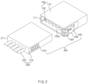
FIG. 2 is a perspective view illustrating a state before first and second connectors are coupled in the connector device according to the first embodiment of the present invention. -
FIG. 3 is a cross-sectional view illustrating a state after the first and second connectors are coupled in the connector device according to the first embodiment of the present invention. -
FIG. 4 is a side view illustrate a state in which a ratchet part is being coupled in the connector device according to the first embodiment of the present invention. -
FIG. 5 is a side view illustrate a state after the ratchet part is coupled in the connector device according to the first embodiment of the present invention. -
FIG. 6 is a perspective view illustrating a connector device according to a second embodiment of the present invention. -
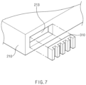
FIG. 7 is a perspective view illustrating a connector device according to a third embodiment of the present invention. -
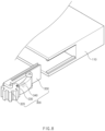
FIG. 8 is a perspective view illustrating a connector device according to a fourth embodiment of the present invention. -
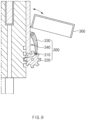
FIG. 9 is a side view illustrating a connector device according to a fifth embodiment of the present invention. -
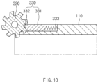
FIG. 10 is a cross-sectional view illustrating a connector device according to a sixth embodiment of the present invention. - Hereinafter, embodiments of the present invention will be described in detail with reference to the accompanying drawings so as to be easily carried out by a person skilled in the art to which the present invention pertains. However, the present invention may be embodied in various different forms, and is not limited to the embodiments described herein. Also, in the drawings, parts irrelevant to the description will be omitted to clearly describe the present invention, and similar elements will be designated by similar reference numerals throughout the specification.
- Meanwhile, in the present invention, a connector device having a structure for connecting a substrate and an electric wire is described as one embodiment. However, a connector device for connecting an electronic device to an electronic device and an electric wire to an electric wire may also be applied in the same manner.
- The connector device according to the first embodiment of the present invention may have a coupling structure using a ratchet as illustrated in
FIGS. 1 to 5 . That is, the connector device according to the first embodiment of the present invention comprises afirst connector 100, asecond connector 200, and aratchet part 300 which couples or separably uncouples thefirst connector 100 and the second connector. - The
first connector 100 is fastened to asubstrate 10, and comprises aterminal body 110 having anopening 100a provided in one surface thereof and aterminal 120 provided in the opening 100a and electrically connected to thesubstrate 10. - The
second connector 200 is fastened to an electric wire 20, and comprises asocket body 210 inserted into the opening 100a of theterminal body 110 and asocket 220 provided inside thesocket body 210 and contacting theterminal 120. - The
ratchet part 300 couples the first connector and the second connector so as not to be separated or uncouples the same so as to be conveniently separable, and comprises atoothed gear 310, aratchet gear 320, astopper 330, and aspring 340. - The
toothed gear 310 is provided on the outer surface (the outer surface on the outside of the socket body when viewed inFIG. 3 ) of thesocket body 210 and comprises a plurality of teeth. - The teeth are provided in a direction (the up-down direction when viewed in
FIG. 3 ) toward theterminal body 110 when thesocket body 210 is inserted into theterminal body 110, and a plurality of teeth are provided at certain intervals. - The
ratchet gear 320 is freely rotatably provided in theterminal body 110 and engages with thetoothed gear 310 when thefirst connector 100 and thesecond connector 200 are coupled, and couples thefirst connector 100 and thesecond connector 200 so as not to be separated when fixed and uncouples thefirst connector 100 and thesecond connector 200 so as to be separable when rotating. - That is, when the
ratchet gear 320 rotates, thefirst connector 100 and thesecond connector 200 may be coupled or separated as thetoothed gear 310 engaging with theratchet gear 320 moves. Also, when theratchet gear 320 is fixed, thefirst connector 100 and thesecond connector 200 may be fixed in a coupled state as thetoothed gear 310 engaging with theratchet gear 320 does not move. - Here, referring to
FIGS. 4 and5 , theratchet gear 320 has, on the outer circumferential surface, a plurality ofgear teeth 321 andgrooves 322 between thegear teeth 321. In each of thegear teeth 321 engaging with thetoothed gear 310, a surface, which faces a direction in which thesecond connector 200 is coupled to thefirst connector 100, (a right side surface of the gear tooth when viewed inFIG. 4 ) is formed as a vertical surface 321b, and a surface, which faces a direction in which thesecond connector 200 is separated from thefirst connector 100, (a left side surface of the gear tooth when viewed inFIG. 4 ) is formed as aninclined surface 321a. - Accordingly, referring to
FIG. 4 , as the stopper is guided along theinclined surface 321a, theratchet gear 320 may rotate in the direction in which thesecond connector 200 is coupled to thefirst connector 100. Also, referring toFIG. 5 , as the stopper is locked to the vertical surface 321b, theratchet gear 320 may not rotate in the direction in which thesecond connector 200 is separated from thefirst connector 100. - The
stopper 330 has a structure by which theratchet gear 320 is fixed so as not to rotate or unfixed so as to be rotatable. That is, as a front end of thestopper 330 is inserted into agroove 322 betweengear teeth 321 of theratchet gear 320, theratchet gear 320 is allowed to rotate only in a direction in which thesecond connector 200 and thefirst connector 100 are coupled. Accordingly, without removing thestopper 330, thesecond connector 200 and thefirst connector 100 may be coupled, but thesecond connector 200 and thefirst connector 100 may not be uncoupled. - That is, when the
ratchet gear 320 is rotated by thetoothed gear 310 as thesecond connector 200 and thefirst connector 100 are coupled, thestopper 330 is guided along theinclined surface 321a provided in thegear tooth 321 of theratchet gear 320 and continuously moves from a groove to another groove of theratchet gear 320. Accordingly, thefirst connector 100 and thesecond connector 200 may be coupled even without removing the front end of thestopper 330 inserted into theratchet gear 320. - That is, when the
ratchet gear 320 is rotated by thetoothed gear 310 as thesecond connector 200 and thefirst connector 100 are separated, thestopper 330 is locked to the vertical surface 321b provided in thegear tooth 321 of theratchet gear 320 and prevents the rotation of theratchet gear 320. Accordingly, thefirst connector 100 and thesecond connector 200 may be uncoupled without removing the front end of thestopper 330 inserted into theratchet gear 320. - The
spring 340 provides an elastic force to maintain a state in which thestopper 330 is inserted into thegroove 322 between thegear teeth 321 of theratchet gear 320. One end is fastened to thefirst connector 100, and the other end is fastened to one side of the front end of thestopper 330. - Meanwhile, the
toothed gear 310 is formed on the outer surface of thesocket body 210 from a point, at which thefirst connector 100 and thesecond connector 200 are coupled by 70% to 80%, to a point at which the coupling is completed. Accordingly, when thefirst connector 100 and thesecond connector 200 are uncoupled by 20% to 30%, thefirst connector 100 and thesecond connector 200 may be conveniently separated. - Hereinafter, a coupling method for the connector device according to the first embodiment of the present invention will be described in more detail.
- When the
first connector 100 and thesecond connector 200 are coupled, theratchet gear 320 provided in thefirst connector 100 is rotated by thetoothed gear 310 provided in thesecond connector 200. Theratchet gear 320 rotates in the direction in which thefirst connector 100 and thesecond connector 200 are coupled. Here, theratchet gear 320 rotates while pushing the front end of thestopper 330 outward from thegroove 322 between thegear teeth 321 of theratchet gear 320, and accordingly, theratchet gear 320 may continuously rotate without interference by thestopper 330. That is, the front end of thestopper 330 is guided along theinclined surface 321a provided in thegear tooth 321 of theratchet gear 320, and thus, does not interfere the rotation of theratchet gear 320. Also, thestopper 330 continuously moves from agroove 322 to anothergroove 322 between thegear teeth 321 of theratchet gear 320 while being pulled in a direction toward the ratchet gear 302 by the elastic force of thespring 340. Thus, thefirst connector 100 and thesecond connector 200 may be coupled even without removing thestopper 330 inserted into theratchet gear 320. - When the
first connector 100 and thesecond connector 200 are separated in a state in which thestopper 330 is inserted into thegroove 322 between thegear teeth 321 of theratchet gear 320, theratchet gear 320 is rotated by thetoothed gear 310 in a direction in which thefirst connector 100 and thesecond connector 200 are separated. Here, theratchet gear 320 does not rotate because not pushes the front end of thestopper 330 outward from thegroove 322 between thegear teeth 321 of theratchet gear 320, that is, because the front end of thestopper 330 does not escape from thegroove 322 between thegear teeth 321 of theratchet gear 320. In other words, as the front end of thestopper 330 is locked to the vertical surface 321b provided in thegear tooth 321 of theratchet gear 320, theratchet gear 320 does not rotate. Thus, thefirst connector 100 and thesecond connector 200 may not be separated in a state in which thestopper 330 is inserted into theratchet gear 320. - When the
first connector 100 and thesecond connector 200 are separated in a state in which thestopper 330 escapes from thegroove 322 between thegear teeth 321 of theratchet gear 320, theratchet gear 320 continuously rotates because thestopper 330 escapes from the groove between the gear teeth of theratchet gear 320, and thetoothed gear 310 is moved by the rotation of theratchet gear 320. Thus, thefirst connector 100 and thesecond connector 200 may be separated in the state in which thestopper 330 escapes from thegroove 322 between thegear teeth 321 of theratchet gear 320. - The connector device having the above configuration according to the first embodiment of the present invention may couple the first connector and the second connector so as not to be easily separated or uncouple the first connector and the second connector so as to be conveniently separable.
- Hereinafter, in describing another embodiment of the present invention, components having the same functions as those in the foregoing embodiment are given the same reference numerals, and their duplicated descriptions will be omitted.
- As illustrated in
FIG. 6 , the connector device according to the second embodiment of the present invention comprises afirst connector 100 provided with aterminal body 110 and asecond connector 200 provided with asocket body 210. - Here, a
guide groove 111 is formed inside theterminal body 110, and aguide protrusion 211 guided along theguide groove 111 is formed in thesocket body 210. - Thus, the connector device according to the second embodiment of the present invention comprises the
guide groove 111 and theguide protrusion 211, and thus, thefirst connector 100 and thesecond connector 200 may be stably coupled or separated. - Meanwhile, a locking
groove 112 connected to theguide groove 111 is formed in one surface of theterminal body 110 in which theguide groove 111 is formed, and a lockingprotrusion 212 locked and supported by the lockinggroove 112 is formed in theguide protrusion 211. - Thus, in the connector device according to the second embodiment of the present invention, the locking
protrusion 212 is locked to the lockinggroove 112 at a set coupling point between thefirst connector 100 and thesecond connector 200. Accordingly, it is possible to prevent thefirst connector 100 and thesecond connector 200 from being coupled beyond the set coupling point. As a result, it is possible to prevent damage which is likely to occur as thefirst connector 100 and thesecond connector 200 are coupled excessively. - As illustrated in
FIG. 7 , the connector device according to the third embodiment of the present invention comprises asocket body 210 and atoothed gear 310. Thetoothed gear 310 is detachably installed on thesocket body 210. - That is, the
toothed gear 310 may be coupled to or separated from acoupling groove 213 formed in thesocket body 210. - Thus, in the connector device according to the third embodiment of the present invention, the toothed gear is detachably coupled to the socket body, and thus, the device may be reused only by replacing a toothed gear worn down by engagement with the ratchet gear. As a result, the easiness of maintenance and repair may be enhanced. Particularly, the toothed gear may be made of a material having higher strength than the socket body, and thus, the use cycle may be significantly extended.
- As illustrated in
FIG. 8 , the connector device according to the fourth embodiment of the present invention comprises aratchet part 300. Theratchet part 300 comprises aratchet body 350 on which aratchet gear 320, astopper 330, and aspring 340 are installed, and theratchet body 350 is detachably coupled to aterminal body 110. - That is, the
ratchet body 350 is inserted into a guide space formed in theratchet body 350 and coupled thereto, or separated therefrom. - Thus, in the connector device according to the fourth embodiment of the present invention, when any one of the
ratchet gear 320, thestopper 330, and thespring 340 is out of order, theratchet body 350 is separated from theterminal body 110. Then, a new ratchet body may be coupled to theterminal body 110, and as a result, the easiness of maintenance and repair may be enhanced. - As illustrated in
FIG. 9 , the connector device according to the fifth embodiment of the present invention comprises aratchet part 300. Theratchet part 300 comprises aratchet gear 320, astopper 330, and aspring 340 which are provided in aterminal body 110. - Particularly, the
terminal body 110 comprises aprotection cover 360 that protects theratchet gear 320, thestopper 330, and thespring 340, and one end of theprotection cover 360 is rotatably coupled to theterminal body 110. That is, theprotection cover 360 may protect theratchet gear 320, thestopper 330, and thespring 340 or may cancel protection. - Thus, the connector device according to the fifth embodiment of the present invention comprises the protection cover, and thus, the
ratchet gear 320, thestopper 330, and thespring 340, which are provided in theterminal body 110, may be more stably protected. - As illustrated in
FIG. 10 , the connector device according to the sixth embodiment of the present invention comprises astopper 330. Thestopper 330 comprises aguide piece 331 which is installed on an outer circumferential surface of theterminal body 110 and is slidable in a direction toward theratchet gear 320 and afixing piece 332 which is inserted into agroove 322 betweengear teeth 321 of theratchet gear 320 and fixes theratchet gear 320 so as not to rotate. - That is, when the
guide piece 331 moves in a direction away from theratchet gear 320, thestopper 330 may allow theratchet gear 320 to rotate as the fixingpiece 332 escapes from thegroove 322 between thegear teeth 321 of theratchet gear 320. That is, when theguide piece 331 moves in a direction closer to theratchet gear 320, theratchet gear 320 may be fixed so as not to rotate, as the fixingpiece 332 is inserted into thegroove 322 between thegear teeth 321 of theratchet gear 320. - Thus, the connector device according to the sixth embodiment of the present invention comprises the stopper that is provided with the guide piece and the fixing piece, and thus, the ratchet gear may be more conveniently fixed or rotated.
- Meanwhile, the connector device according to the sixth embodiment of the present invention may further comprise a
spring 333 that provides an elastic force so thatstopper 330 is directed toward theratchet gear 320. - The scope of the present invention is defined by the appended claims rather than the detailed description, and various embodiments derived from the meaning and scope of the claims and their equivalent concepts are also possible.
-
- 10: Substrate
- 20: Electric wire
- 100: First connector
- 100a: Opening
- 110: Terminal body
- 111: Guide groove
- 112: Locking groove
- 120: Terminal
- 200: Second connector
- 210: Socket body
- 211: Guide protrusion
- 212: Locking protrusion
- 220: Socket
- 300: Ratchet part
- 310: Toothed gear
- 320: Ratchet gear
- 321: Gear tooth
- 321a: Inclined surface
- 321b: Vertical surface
- 322: Groove
- 330: Stopper
- 331: Guide piece
- 332: Fixing piece
- 340: Spring
- 350: Ratchet body
- 360: Protection cover
Claims (13)
- A connector device comprising:a first connector which is fastened to a substrate, and comprises a terminal body having an opening provided in one surface thereof and a terminal provided in the opening and electrically connected to the substrate;a second connector which is fastened to an electric wire, and comprises a socket body inserted into the opening of the terminal body and a socket provided inside the socket body and contacting the terminal; anda ratchet part by which the first connector and the second connector are coupled so as not to be separated or uncoupled so as to be separable,wherein the ratchet part comprises:a toothed gear which is provided on an outer surface of the socket body and has teeth provided in a direction toward the terminal body when the socket body is inserted into the terminal body;a ratchet gear which is provided in the terminal body and engages with the toothed gear, and couples the first connector and the second connector so as not to be separated when fixed and uncouples the first connector and the second connector so as to be separable when rotating; anda stopper by which the ratchet gear is fixed so as not to rotate or unfixed so as to be rotatable.
- The connector device of claim 1, wherein, as a front end of the stopper is inserted into a groove between gear teeth of the ratchet gear, the ratchet gear is allowed to rotate only in a direction in which the second connector and the first connector are coupled.
- The connector device of claim 1, wherein the ratchet part further comprises a spring that provides an elastic force to maintain a state in which the stopper is inserted into a groove between gear teeth of the ratchet gear.
- The connector device of claim 3, wherein, when the first connector and the second connector are coupled, the ratchet gear is rotated by the toothed gear in a direction in which the first connector and the second connector are coupled,
wherein the ratchet gear rotates while pushing the front end of the stopper outward from the groove between the gear teeth of the ratchet gear and thus rotates without interference by the stopper, and the stopper continuously moves from a groove to another groove between the gear teeth of the ratchet gear while being pulled in a direction toward the ratchet gear by the elastic force of the spring. - The connector device of claim 3, wherein, when the first connector and the second connector are separated in a state in which the stopper is inserted into the groove between the gear teeth of the ratchet gear, the ratchet gear is rotated by the toothed gear in a direction in which the first connector and the second connector are separated,
wherein the ratchet gear presses the front end of the stopper inward from the groove between the gear teeth of the ratchet gear and thus does not rotate because the front end of the stopper does not escape from the groove between the gear teeth of the ratchet gear, and as the toothed gear is not moved by the ratchet gear, the first connector and the second connector are not separated. - The connector device of claim 3, wherein, when the first connector and the second connector are separated in a state in which the stopper escapes from the groove between the gear teeth of the ratchet gear, the ratchet gear continuously rotates because the stopper escapes from the groove between the gear teeth of the ratchet gear, and as the toothed gear is moved by rotation of the ratchet gear, the first connector and the second connector are separated.
- The connector device of claim 3, wherein the ratchet part further comprises a ratchet body which is detachably coupled to the terminal body and on which the ratchet gear, the stopper, and the spring are installed.
- The connector device of claim 1, wherein a guide groove is formed inside the terminal body, and a guide protrusion guided along the guide groove is formed in the socket body.
- The connector device of claim 8, wherein a locking groove connected to the guide groove is formed in one surface of the terminal body in which the guide groove is formed, and
a locking protrusion locked and supported by the locking groove is formed in the guide protrusion. - The connector device of claim 1, wherein the toothed gear is detachably installed on the socket body.
- The connector device of claim 1, wherein the first connector further comprises a protection cover that protects the ratchet gear and the stopper provided in the terminal body.
- The connector device of claim 11, wherein one end of the protection cover is rotatably coupled to the terminal body.
- The connector device of claim 1, wherein the stopper comprises a guide piece, which is installed on an outer circumferential surface of the terminal body and is slidable in a direction toward the ratchet gear, and a fixing piece, which is inserted into a groove between gear teeth of the ratchet gear and fixes the ratchet gear so as not to rotate.
Applications Claiming Priority (2)
| Application Number | Priority Date | Filing Date | Title |
|---|---|---|---|
| KR1020200111915A KR102712536B1 (en) | 2020-09-02 | 2020-09-02 | Connector device |
| PCT/KR2021/010823 WO2022050593A1 (en) | 2020-09-02 | 2021-08-13 | Connector device |
Publications (3)
| Publication Number | Publication Date |
|---|---|
| EP4181325A1 true EP4181325A1 (en) | 2023-05-17 |
| EP4181325A4 EP4181325A4 (en) | 2023-12-13 |
| EP4181325B1 EP4181325B1 (en) | 2026-03-18 |
Family
ID=80491134
Family Applications (1)
| Application Number | Title | Priority Date | Filing Date |
|---|---|---|---|
| EP21864554.7A Active EP4181325B1 (en) | 2020-09-02 | 2021-08-13 | Connector device |
Country Status (6)
| Country | Link |
|---|---|
| US (1) | US12482965B2 (en) |
| EP (1) | EP4181325B1 (en) |
| JP (1) | JP7509364B2 (en) |
| KR (1) | KR102712536B1 (en) |
| CN (1) | CN116034521A (en) |
| WO (1) | WO2022050593A1 (en) |
Families Citing this family (1)
| Publication number | Priority date | Publication date | Assignee | Title |
|---|---|---|---|---|
| CN118783182B (en) * | 2024-08-09 | 2025-11-11 | 东莞市本末科技有限公司 | Robot butt joint connector |
Family Cites Families (29)
| Publication number | Priority date | Publication date | Assignee | Title |
|---|---|---|---|---|
| JPS53128888U (en) * | 1977-03-23 | 1978-10-13 | ||
| US4537454A (en) * | 1983-07-25 | 1985-08-27 | Amp Incorporated | Intercard-extraction means |
| JPH0234773Y2 (en) * | 1986-12-19 | 1990-09-19 | ||
| US4931907A (en) | 1989-03-30 | 1990-06-05 | Tandem Computers Incorporated | Electric module latch assembly |
| JP2587276Y2 (en) | 1991-11-12 | 1998-12-16 | 日本エー・エム・ピー株式会社 | Lever drive type connector |
| JP2597876Y2 (en) | 1993-03-30 | 1999-07-19 | 矢崎総業株式会社 | Low insertion force connector |
| EP0653812A1 (en) | 1993-10-01 | 1995-05-17 | Siemens Aktiengesellschaft | Electrical connector |
| JPH09204961A (en) | 1996-01-25 | 1997-08-05 | Yazaki Corp | Low insertion / extraction force connector |
| KR19980059217U (en) | 1997-02-20 | 1998-10-26 | 랄프홀거베렌스 | Electronic connector |
| JPH10334994A (en) | 1997-05-29 | 1998-12-18 | Japan Aviation Electron Ind Ltd | Connector device |
| JP2004199905A (en) | 2002-12-16 | 2004-07-15 | Fujikura Ltd | Low insertion force connector |
| JP2008112678A (en) | 2006-10-31 | 2008-05-15 | Tamron Co Ltd | Cabling member, optical apparatus, and imaging apparatus |
| KR20090073906A (en) | 2007-12-31 | 2009-07-03 | 한국단자공업 주식회사 | Connector assembly |
| US8297992B2 (en) * | 2008-09-26 | 2012-10-30 | Fci Automotive Holding | Electrical connector assembly having locking device |
| KR101025594B1 (en) | 2008-10-28 | 2011-03-30 | 주식회사 유라코퍼레이션 | Side bolting connector with rail coupling structure |
| KR200463785Y1 (en) | 2010-12-20 | 2012-12-05 | 조정민 | Flexible electric plug |
| KR200453565Y1 (en) * | 2011-01-21 | 2011-05-16 | 주식회사 협진아이엔씨 | Connector for electronic devices with elastic support |
| KR200466204Y1 (en) | 2011-07-15 | 2013-04-03 | 공윤옥 | Moveable concent on the wall |
| CN202259947U (en) | 2011-09-30 | 2012-05-30 | 四川华丰企业集团有限公司 | Connector locating part used for locomotive |
| JP2013098055A (en) | 2011-11-01 | 2013-05-20 | Furukawa Electric Co Ltd:The | Electric connector |
| KR20140040319A (en) * | 2012-09-24 | 2014-04-03 | 김기성 | Socket wrench for working at narrow width area |
| JP7032046B2 (en) | 2016-01-22 | 2022-03-08 | 旭化成メディカル株式会社 | Continuous constant flow rate purification method for bioactive substances |
| KR102552482B1 (en) | 2016-09-08 | 2023-07-06 | 현대자동차주식회사 | Joint connector device |
| JP6852894B2 (en) | 2017-06-14 | 2021-03-31 | 日本圧着端子製造株式会社 | connector |
| CN207426301U (en) | 2017-10-30 | 2018-05-29 | 宁波市重强电器有限公司 | A kind of anti-drop connector |
| KR101982591B1 (en) | 2017-11-02 | 2019-06-03 | 정용기 | Rachet Buckle for building safety net |
| US11047407B2 (en) * | 2017-12-22 | 2021-06-29 | Ting-Jui Wang | Quick release connecting device |
| JP6654685B2 (en) | 2018-01-10 | 2020-02-26 | デルファイ・テクノロジーズ・エルエルシー | Connector assembly with variable axial assistance |
| KR20200111915A (en) | 2019-03-20 | 2020-10-05 | 주식회사 현대엘앤씨 | Window-integrated air conditioner for smart window system implementation |
-
2020
- 2020-09-02 KR KR1020200111915A patent/KR102712536B1/en active Active
-
2021
- 2021-08-13 JP JP2023509451A patent/JP7509364B2/en active Active
- 2021-08-13 CN CN202180056925.6A patent/CN116034521A/en active Pending
- 2021-08-13 WO PCT/KR2021/010823 patent/WO2022050593A1/en not_active Ceased
- 2021-08-13 US US18/006,298 patent/US12482965B2/en active Active
- 2021-08-13 EP EP21864554.7A patent/EP4181325B1/en active Active
Also Published As
| Publication number | Publication date |
|---|---|
| JP2023537740A (en) | 2023-09-05 |
| WO2022050593A1 (en) | 2022-03-10 |
| KR20220030114A (en) | 2022-03-10 |
| JP7509364B2 (en) | 2024-07-02 |
| EP4181325A4 (en) | 2023-12-13 |
| KR102712536B1 (en) | 2024-10-04 |
| US12482965B2 (en) | 2025-11-25 |
| EP4181325B1 (en) | 2026-03-18 |
| US20230307855A1 (en) | 2023-09-28 |
| CN116034521A (en) | 2023-04-28 |
Similar Documents
| Publication | Publication Date | Title |
|---|---|---|
| CN104798261B (en) | RJ45 connector with stress release device | |
| KR101068316B1 (en) | Lever Type Connector Assembly | |
| US20180323549A1 (en) | Hybrid plug connector | |
| US20150364875A1 (en) | Mobile device case with retractable cable | |
| JP5970399B2 (en) | Waterproof connector | |
| JP2016149362A (en) | Connector with pre-assembled conduit adapter | |
| US12482965B2 (en) | Connector device | |
| CN101621164A (en) | Cover-equipped connector | |
| CN104051872B (en) | Plug-in connector for data and/or communication cable with multiple core wires | |
| US9761993B2 (en) | Banana plug | |
| JP2004214064A (en) | Power receptacle and plug connection set | |
| EP3540868B1 (en) | Locking electrical receptacle | |
| JP6208206B2 (en) | Method for manufacturing terminal protector and charging connector | |
| KR102015003B1 (en) | Terminal case | |
| KR101037721B1 (en) | Insulation structure of underground distribution box for preventing electric shock | |
| JP6174554B2 (en) | Shield connector layout | |
| CN106067607A (en) | A kind of easy installation crimps firm jointing clamp of electric meter | |
| KR101405767B1 (en) | Joint apparatus for wiring harness chain-door of sliding door | |
| JP2023077201A (en) | connector stopper | |
| JP2017059347A (en) | Wire harness | |
| CN209767054U (en) | Automobile wire harness corner sheath | |
| WO2021192958A1 (en) | Terminal cover | |
| JP2013251115A (en) | Electric wire protective structure | |
| KR200413810Y1 (en) | connector | |
| KR20090003443U (en) | Stomach Tube |
Legal Events
| Date | Code | Title | Description |
|---|---|---|---|
| STAA | Information on the status of an ep patent application or granted ep patent |
Free format text: STATUS: THE INTERNATIONAL PUBLICATION HAS BEEN MADE |
|
| PUAI | Public reference made under article 153(3) epc to a published international application that has entered the european phase |
Free format text: ORIGINAL CODE: 0009012 |
|
| STAA | Information on the status of an ep patent application or granted ep patent |
Free format text: STATUS: REQUEST FOR EXAMINATION WAS MADE |
|
| 17P | Request for examination filed |
Effective date: 20230207 |
|
| AK | Designated contracting states |
Kind code of ref document: A1 Designated state(s): AL AT BE BG CH CY CZ DE DK EE ES FI FR GB GR HR HU IE IS IT LI LT LU LV MC MK MT NL NO PL PT RO RS SE SI SK SM TR |
|
| REG | Reference to a national code |
Ref country code: DE Ref legal event code: R079 Ref country code: DE Ref legal event code: R079 Ref document number: 602021050338 Country of ref document: DE Free format text: PREVIOUS MAIN CLASS: H01R0013627000 Ipc: H01R0013639000 |
|
| DAV | Request for validation of the european patent (deleted) | ||
| DAX | Request for extension of the european patent (deleted) | ||
| A4 | Supplementary search report drawn up and despatched |
Effective date: 20231114 |
|
| RIC1 | Information provided on ipc code assigned before grant |
Ipc: H01R 107/00 20060101ALI20231108BHEP Ipc: F16H 19/04 20060101ALI20231108BHEP Ipc: H01R 24/60 20110101ALI20231108BHEP Ipc: H01R 13/627 20060101ALI20231108BHEP Ipc: H01R 13/639 20060101AFI20231108BHEP |
|
| GRAP | Despatch of communication of intention to grant a patent |
Free format text: ORIGINAL CODE: EPIDOSNIGR1 |
|
| STAA | Information on the status of an ep patent application or granted ep patent |
Free format text: STATUS: GRANT OF PATENT IS INTENDED |
|
| INTG | Intention to grant announced |
Effective date: 20251118 |
|
| P01 | Opt-out of the competence of the unified patent court (upc) registered |
Free format text: CASE NUMBER: UPC_APP_0015352_4181325/2025 Effective date: 20251201 |
|
| GRAS | Grant fee paid |
Free format text: ORIGINAL CODE: EPIDOSNIGR3 |
|
| GRAA | (expected) grant |
Free format text: ORIGINAL CODE: 0009210 |
|
| STAA | Information on the status of an ep patent application or granted ep patent |
Free format text: STATUS: THE PATENT HAS BEEN GRANTED |
|
| AK | Designated contracting states |
Kind code of ref document: B1 Designated state(s): AL AT BE BG CH CY CZ DE DK EE ES FI FR GB GR HR HU IE IS IT LI LT LU LV MC MK MT NL NO PL PT RO RS SE SI SK SM TR |
|
| REG | Reference to a national code |
Ref country code: CH Ref legal event code: F10 Free format text: ST27 STATUS EVENT CODE: U-0-0-F10-F00 (AS PROVIDED BY THE NATIONAL OFFICE) Effective date: 20260318 Ref country code: GB Ref legal event code: FG4D |
|
| REG | Reference to a national code |
Ref country code: DE Ref legal event code: R096 Ref document number: 602021050338 Country of ref document: DE |
|
| REG | Reference to a national code |
Ref country code: IE Ref legal event code: FG4D |
|
| REG | Reference to a national code |
Ref country code: ES Ref legal event code: FG2A Ref document number: 3066669 Country of ref document: ES Kind code of ref document: T3 Effective date: 20260514 |