EP4181323A1 - Connector assembly - Google Patents
Connector assembly Download PDFInfo
- Publication number
- EP4181323A1 EP4181323A1 EP21213495.1A EP21213495A EP4181323A1 EP 4181323 A1 EP4181323 A1 EP 4181323A1 EP 21213495 A EP21213495 A EP 21213495A EP 4181323 A1 EP4181323 A1 EP 4181323A1
- Authority
- EP
- European Patent Office
- Prior art keywords
- insulating part
- insulating
- end section
- inner signal
- connector assembly
- Prior art date
- Legal status (The legal status is an assumption and is not a legal conclusion. Google has not performed a legal analysis and makes no representation as to the accuracy of the status listed.)
- Pending
Links
Images











Classifications
-
- H—ELECTRICITY
- H01—ELECTRIC ELEMENTS
- H01R—ELECTRICALLY-CONDUCTIVE CONNECTIONS; STRUCTURAL ASSOCIATIONS OF A PLURALITY OF MUTUALLY-INSULATED ELECTRICAL CONNECTING ELEMENTS; COUPLING DEVICES; CURRENT COLLECTORS
- H01R13/00—Details of coupling devices of the kinds covered by groups H01R12/70 or H01R24/00 - H01R33/00
- H01R13/02—Contact members
- H01R13/10—Sockets for co-operation with pins or blades
-
- H—ELECTRICITY
- H01—ELECTRIC ELEMENTS
- H01R—ELECTRICALLY-CONDUCTIVE CONNECTIONS; STRUCTURAL ASSOCIATIONS OF A PLURALITY OF MUTUALLY-INSULATED ELECTRICAL CONNECTING ELEMENTS; COUPLING DEVICES; CURRENT COLLECTORS
- H01R13/00—Details of coupling devices of the kinds covered by groups H01R12/70 or H01R24/00 - H01R33/00
- H01R13/46—Bases; Cases
- H01R13/502—Bases; Cases composed of different pieces
- H01R13/506—Bases; Cases composed of different pieces assembled by snap action of the parts
-
- H—ELECTRICITY
- H01—ELECTRIC ELEMENTS
- H01R—ELECTRICALLY-CONDUCTIVE CONNECTIONS; STRUCTURAL ASSOCIATIONS OF A PLURALITY OF MUTUALLY-INSULATED ELECTRICAL CONNECTING ELEMENTS; COUPLING DEVICES; CURRENT COLLECTORS
- H01R13/00—Details of coupling devices of the kinds covered by groups H01R12/70 or H01R24/00 - H01R33/00
- H01R13/02—Contact members
- H01R13/10—Sockets for co-operation with pins or blades
- H01R13/11—Resilient sockets
- H01R13/111—Resilient sockets co-operating with pins having a circular transverse section
-
- H—ELECTRICITY
- H01—ELECTRIC ELEMENTS
- H01R—ELECTRICALLY-CONDUCTIVE CONNECTIONS; STRUCTURAL ASSOCIATIONS OF A PLURALITY OF MUTUALLY-INSULATED ELECTRICAL CONNECTING ELEMENTS; COUPLING DEVICES; CURRENT COLLECTORS
- H01R13/00—Details of coupling devices of the kinds covered by groups H01R12/70 or H01R24/00 - H01R33/00
- H01R13/02—Contact members
- H01R13/10—Sockets for co-operation with pins or blades
- H01R13/11—Resilient sockets
- H01R13/115—U-shaped sockets having inwardly bent legs, e.g. spade type
-
- H—ELECTRICITY
- H01—ELECTRIC ELEMENTS
- H01R—ELECTRICALLY-CONDUCTIVE CONNECTIONS; STRUCTURAL ASSOCIATIONS OF A PLURALITY OF MUTUALLY-INSULATED ELECTRICAL CONNECTING ELEMENTS; COUPLING DEVICES; CURRENT COLLECTORS
- H01R13/00—Details of coupling devices of the kinds covered by groups H01R12/70 or H01R24/00 - H01R33/00
- H01R13/40—Securing contact members in or to a base or case; Insulating of contact members
-
- H—ELECTRICITY
- H01—ELECTRIC ELEMENTS
- H01R—ELECTRICALLY-CONDUCTIVE CONNECTIONS; STRUCTURAL ASSOCIATIONS OF A PLURALITY OF MUTUALLY-INSULATED ELECTRICAL CONNECTING ELEMENTS; COUPLING DEVICES; CURRENT COLLECTORS
- H01R13/00—Details of coupling devices of the kinds covered by groups H01R12/70 or H01R24/00 - H01R33/00
- H01R13/40—Securing contact members in or to a base or case; Insulating of contact members
- H01R13/42—Securing in a demountable manner
- H01R13/422—Securing in resilient one-piece base or case, e.g. by friction; One-piece base or case formed with resilient locking means
-
- H—ELECTRICITY
- H01—ELECTRIC ELEMENTS
- H01R—ELECTRICALLY-CONDUCTIVE CONNECTIONS; STRUCTURAL ASSOCIATIONS OF A PLURALITY OF MUTUALLY-INSULATED ELECTRICAL CONNECTING ELEMENTS; COUPLING DEVICES; CURRENT COLLECTORS
- H01R13/00—Details of coupling devices of the kinds covered by groups H01R12/70 or H01R24/00 - H01R33/00
- H01R13/62—Means for facilitating engagement or disengagement of coupling parts or for holding them in engagement
- H01R13/629—Additional means for facilitating engagement or disengagement of coupling parts, e.g. aligning or guiding means, levers, gas pressure electrical locking indicators, manufacturing tolerances
- H01R13/631—Additional means for facilitating engagement or disengagement of coupling parts, e.g. aligning or guiding means, levers, gas pressure electrical locking indicators, manufacturing tolerances for engagement only
-
- H—ELECTRICITY
- H01—ELECTRIC ELEMENTS
- H01R—ELECTRICALLY-CONDUCTIVE CONNECTIONS; STRUCTURAL ASSOCIATIONS OF A PLURALITY OF MUTUALLY-INSULATED ELECTRICAL CONNECTING ELEMENTS; COUPLING DEVICES; CURRENT COLLECTORS
- H01R13/00—Details of coupling devices of the kinds covered by groups H01R12/70 or H01R24/00 - H01R33/00
- H01R13/648—Protective earth or shield arrangements on coupling devices, e.g. anti-static shielding
-
- H—ELECTRICITY
- H01—ELECTRIC ELEMENTS
- H01R—ELECTRICALLY-CONDUCTIVE CONNECTIONS; STRUCTURAL ASSOCIATIONS OF A PLURALITY OF MUTUALLY-INSULATED ELECTRICAL CONNECTING ELEMENTS; COUPLING DEVICES; CURRENT COLLECTORS
- H01R24/00—Two-part coupling devices, or either of their cooperating parts, characterised by their overall structure
- H01R24/20—Coupling parts carrying sockets, clips or analogous contacts and secured only to wire or cable
-
- H—ELECTRICITY
- H01—ELECTRIC ELEMENTS
- H01R—ELECTRICALLY-CONDUCTIVE CONNECTIONS; STRUCTURAL ASSOCIATIONS OF A PLURALITY OF MUTUALLY-INSULATED ELECTRICAL CONNECTING ELEMENTS; COUPLING DEVICES; CURRENT COLLECTORS
- H01R13/00—Details of coupling devices of the kinds covered by groups H01R12/70 or H01R24/00 - H01R33/00
- H01R13/648—Protective earth or shield arrangements on coupling devices, e.g. anti-static shielding
- H01R13/658—High frequency shielding arrangements, e.g. against EMI [Electro-Magnetic Interference] or EMP [Electro-Magnetic Pulse]
- H01R13/6591—Specific features or arrangements of connection of shield to conductive members
- H01R13/65912—Specific features or arrangements of connection of shield to conductive members for shielded multiconductor cable
- H01R13/65915—Twisted pair of conductors surrounded by shield
Definitions
- the present disclosure relates to a connector assembly, preferably for multi GHz applications.
- the disclosure relates to an H-MTD ® (High Speed Modular Twisted-Pair-Data) connector assembly.
- H-MTD ® High Speed Modular Twisted-Pair-Data
- H-MTD ® system has been established by a company called "Rosenberger Hochfrequenztechnik GmbH & Co. KG".
- Applications for the H-MTD ® system are 4K camera systems, autonomous driving, radar, lidar, high-resolution displays and rear seat entertainment. Connectors of said system are meant to allow data transmission up to 15 GHz or 20 Gbps while having a small package size.
- every tenth of a millimeter of the interconnection channel and of the signal connectors should be within a certain data transmission (differential) impedance bandwidth (typical 100 +/- 5 ⁇ ) and should be matched to preceding and succeeding sections.
- metal portions of an inner contact or signal contact and an outer contact or shielding, insulating material of an insulating element and any air gaps must be balanced in size and position with respect to each other.
- these components there is also a need for these components to meet other non-signal-integrity requirements, in particular mechanical requirements. For example, it has to be ensured that a male signal contact is always correctly guided into a corresponding female signal contact.
- an optimum electrical and mechanical connection between a male signal contact and a female signal contact is indispensable.
- the present disclosure is directed at a connector assembly, wherein the connector assembly comprises at least one elongated inner signal contact having a first connection portion, wherein the first connection portion comprises a tube-like main section and a funnel-shaped end section; and an insulating element, wherein the insulating element defines at least one elongated cavity designed to accommodate the elongated inner signal contact, wherein a maximum outer cross-sectional dimension of the funnel-shaped end section is greater than a minimum cross-sectional dimension of the elongated cavity.
- the connector assembly may be configured for high speed data transmission.
- the connector assembly may be of the H-MTD ® type for automotive applications.
- the connector assembly described herein is a female connector assembly, i.e. the inner signal contact is a female signal contact.
- the inner signal contact has a funnel-shaped end section allowing for pin movement, i.e. allowing insertion of a male signal contact pin.
- the inner signal contact is embedded in an insulating element which may form a one-part housing or a multi-part housing, in particular a two-part housing. More specifically, the insulating element may define a cavity having a first cavity portion which receives the tube-like main section of the inner signal contact, and a second cavity portion which receives the funnel-shaped end section of the inner signal contact.
- a cross-sectional dimension of the first cavity portion also referred to as a minimum cross-sectional dimension of the cavity, and an outer cross-sectional dimension of the tube-like main section may be substantially equal, i.e. the tube-like main section may be embedded in the first cavity portion with marginal clearance between the tube-like main section and the insulating material defining the first cavity portion.
- a maximum outer cross-sectional dimension of the funnel-shaped end section is greater than the outer cross-sectional dimension of the tube-like main section. Consequently, the maximum outer cross-sectional dimension of the funnel-shaped end section is also greater than the cross-sectional dimension of the first cavity portion, i.e. the minimum cross-sectional dimension of the cavity, thereby making it generally impossible for the inner signal contact to be pushed along the length of the cavity.
- the cross-sectional dimension of the second cavity portion also referred to as a maximum cross-sectional dimension of the cavity, must at least correspond to the maximum outer cross-sectional dimension of the funnel-shaped end section and as such is also greater than the minimum cross-sectional dimension of the cavity.
- the funnel-shaped end section may comprise a first end section part and a second end section part, wherein the first end section part and the second end section part are separated by two air gaps.
- the air gaps may be diagonally arranged, i.e. the two air gaps are arranged opposite from each other.
- the first end section and the second end section of the funnel-shaped end section allow a spreading apart of the funnel-shaped end section to thereby make the insertion of a male signal contact pin easier.
- the funnel-shaped end section may be a machined end section or a stamped, rolled, or bended end section, in which a first end section part and a second end section part are separated by just one small slit.
- the insulating element may comprise at least one front opening configured to receive the funnel-shaped end section, and two chamfers protruding into the air gaps such that the first end section part, the second end section part and the two chamfers define an inlet.
- the chamfers may radially protrude into the front opening.
- the two chamfers may be arranged diagonally to each other.
- the front opening of the insulating element may be configured to receive a male signal contact, and the inlet serves to lead the male signal contact into the female inner signal contact of the connector assembly.
- the inlet may provide an at least approximately 360° lead-in cone to guide the male signal contact into the tube-like main section of the female inner signal contact.
- the funnel-shaped end section comprises a first end section part and a second end section part, wherein the first end section part and the second end section part are separated by two air gaps, and wherein the insulating element comprises at least one rib engaging one of the air gaps and thereby widening the funnel-shaped end section.
- the size of the inlet may be maximized.
- the two air gaps may be arranged diagonally to each other.
- the insulating element and the at least one elongated inner signal contact may comprise at least one protrusion and at least one recess, respectively, wherein the protrusion and the recess are configured to cooperate in order to at least reduce or even prevent a rotation and/or an axial movement of the at least one elongated inner signal contact relative to the insulating element.
- the at least one protrusion may be a blocking element that provides a forward stop and/or a backward stop for the at least one elongated inner signal contact in the insulating element. A precise rotational control and limitation of movement of the inner signal contact as well as a precise rigid back and forward stop of the inner signal contact may thus be achieved.
- the insulating element may comprise a control element and the at least one elongated inner signal contact may comprise a hole receiving the control element when the connector assembly is correctly assembled.
- the control element may be visible in the hole of the at least one elongated inner signal contact when the at least one elongated inner signal contact reaches its correct end-position during assembling.
- the insulating element may comprise at least one clamping element configured to secure a wire to which the at least one elongated inner signal contact is connected.
- the at least one elongated inner signal contact may comprise a termination element configured to receive a wire and the insulating element may comprise at least one retaining element configured to secure the termination element and/or the wire in the insulating element.
- the termination element may comprise a pair of crimping wings or any other suitable termination means.
- the insulating element may comprise a first insulating part and a second insulating part, wherein the first insulating part and the second insulating part together surround the at least one inner signal contact.
- first and second are only used to differentiate the two insulation parts. There is no restriction to features concerning the first insulating part or the second insulating part, i.e. all features of the first insulating part may be also features of the second insulating part.
- one of the first insulating part and the second insulating part may be configured to be radially mounted in respect of the at least one elongated inner signal contact and the respective other one of the first insulating part and the second insulating part is configured to be axially slid onto the at least one elongated inner signal contact.
- the at least one elongated inner signal contact may be pinched into the first insulating part or the second insulating part.
- the first insulating part or the second insulating part may comprise a press fit element configured to secure the first insulating part to the second insulating part.
- the first insulating part or the second insulating part may comprise at least one locking element configured to snap fit the first insulating part and the second insulating part together and thereby secure the first insulating part to the second insulating part.
- the locking element may provide a passive lock and/or an active lock.
- the first insulating part or the second insulating part may comprise a pin and the respective other one of the first insulating part and the second insulating part comprises a slot, wherein the slot is configured to receive the pin and the pin is deformed and secured in the slot to thereby secure the first insulating part to the second insulating part.
- the first insulating part or the second insulating part may comprise a groove and the respective other one of the first insulating part and the second insulating part may comprise a tongue received in the groove.
- the first insulating part or the second insulating part may comprise a locking cavity and the respective other one of the first insulating part and the second insulating part may comprise a locking protrusion received in the locking cavity.
- Fig. 1 depicts an exploded view of a connector 10, in particular a female connector, comprising two elongated inner signal contacts 12 arranged generally parallel to each other along an axial direction 14 of the connector 10.
- the signal contacts 12 have a first connection portion 16 for connecting the connector 10 to a mating connector, in particular a male connector, and a second connection portion 18 for connecting the signal contacts 12 to respective conductors 21 of a cable 22.
- the conductors 21 may be strands.
- the conductors 21 may be embedded in a wire insulation 20.
- the second connection portion 18 may include a termination element 24 comprising, for example, two crimping wings (shown in Figs. 3A and 3B ) or may have a welding portion having a welding opening 26 (shown in Fig. 3C ).
- the welding opening 26 may be used to connect the signal contacts 12 to respective conductors 21 of the cable 22 via laser welding or ultrasonic welding. Alternatively, resistance welding can be used to connect the signal contacts 12 to respective conductor
- the inner signal contacts 12 are arranged in an insulating element 28 which may form a di-electric housing.
- the insulating element 28 comprises two separate insulating parts, a first insulating part 28a and a second insulating part 28b, which together enclose the inner signal contacts 12.
- the first insulating part 28a and the second insulating part 28b may be attached to each other, for example, by a click-on connection, i.e. by a snap fit engagement. It is to be understood that the first insulating part 28a and the second insulating part 28b may be attached to each other by other suitable connections, as will be described further below.
- the insulating element 28 may also be a one-part insulating element 28, for example, produced by injection molding, i.e. by overmolding the inner signal contacts 12. In such an insulating element 28, undesirable air pockets may be minimized.
- the first insulating part 28a fulfills the task of locking the signal contacts 12 in the axial direction 14 so that the inner signal contacts 12 maintain their axial position when the connector 10 is connected to a mating connector. It is to be understood that, additionally or alternatively, the second insulating part 28b may fulfill the task of locking the signal contacts 12 in the axial direction 14.
- the connector 10 further comprises a first shielding part 31 and a second shielding part 33 both formed as half shells which together form an outer shielding contact 35.
- the outer shielding contact 35 surrounds the inner signal contacts 12 and the insulating element 28 to provide a shield against interfering signals.
- the outer shielding contact 35 can also be used as an electrical conductor to transport electric power.
- the connector 10 comprises multiple shielding contacts 39.
- the first shielding part 31 forms a cover 43.
- the second shielding part 33 forms a crimping portion 45 at the proximal end 41 of the connector 10 to mechanically and electrically connect the outer shielding contact 35 to the cable 22.
- the connector 10 comprises an inner crimp ferrule 47 which is placed around the cable 22.
- Fig. 2B shows an exploded view of the connector assembly 110.
- Figs. 3A, 3B and 3C depict a perspective view of the inner signal contacts 12 according to various embodiments.
- the inner signal contacts 12 generally extend parallel to one another.
- Each inner signal contact 12 has a first connection portion 16 for connecting the signal contact 12 to a mating signal contact and a second connection portion 18 for connecting the signal contact 12 to a respective conductor 21 of a cable 22 ( Fig. 1 ).
- the first connection portion 16 has a tube-like main section 29 defining a first centre axis 98 and a funnel-shaped end section 30, wherein the tube-like main section 29 may have a round, in particular a generally circular or oval, or a polygonal cross-section.
- the second connection portion 18 defines a second centre axis 100 where a centre axis of the cable 22 is placed at.
- a distance A between the centre axes 98 of the first connection portions 16 may be equal or larger than a distance B between the centre axes 100 of the second connection portions 18.
- a distance A between the centre axes 98 of the first connection portions 16 may be smaller than a distance B between the centre axes 100 of the second connection portions 18.
- the inner signal contacts 12 may be formed so that a pitch translation may be generated.
- Each of the inner signal contacts 12 may be formed so that the first centre axis 98 is spaced apart in parallel from the second centre axis 100.
- the inner signal contacts 12 differ from the inner signal contacts 12 of Figs. 3A and 3B in that hooks 103 are formed at side surfaces of the first connection portions 16. The hooks 103 help to axially fix the inner signal contacts 12 in the insulating element 28.
- the second connection portions 18 of the inner signal contacts 12 may comprise welding openings 26 ( Fig. 3C ) that are arranged to allow, for example, a laser beam to weld a conductor 21 to the inner signal contacts 12.
- termination elements 24 can be formed at the second connection portions 18 so that the inner signal contacts 12 can be attached onto the wires insulating 20 of the cable 22 ( Figs. 3A and 3B ).
- the inner signal contacts 12 may comprise signal contact portions 50.
- the signal contact portions 50 may have an oval cross-section, as shown in Fig. 3A .
- the signal contact portions 50 may have a U-shaped cross-section, as shown in Fig. 3B .
- the signal contact portions 50 may have a circular cross-section, as shown in Fig. 3C .
- the shape of the signal contact portions 50 is not limited to the shapes shown in Figs. 3A to 3C . Rather, the signal contact portions 50 may be of any suitable shape.
- the signal portions 50 may be configured to at least reduce or even prevent a rotation and/or an axial movement of the at least one elongated inner signal contact 12 relative to the insulating element 28.
- the signal portions 50 may be defined as blocking elements that provide a forward stop and/or a backward stop for the at least one elongated inner signal contact 12 in the insulating element 28. A precise rotational control and limitation of movement of the inner signal contact 12 as well as a precise rigid back and forward stop of the inner signal contact 12 may thus be achieved.
- the signal portions 50 may also be configured to receive a wire insulation 20.
- Figs. 4A and 4B show cross-sectional views of a connector assembly 110 in a partly assembled state ( Fig. 4A ) and in a fully assembled state ( Fig. 4B ).
- the connector assembly 110 comprises at least one elongated inner signal contact 12, in the present embodiment two inner signal contacts 12.
- Each inner signal contact 12 comprises a first connection portion 16 having a tube-like main section 29 and a funnel-shaped end section 30.
- the tube-like main section 29 may have a round, in particular a generally circular or oval, or a polygonal cross-section.
- the funnel-shaped end section 30 expands from one end of the tube-like main section 29 such that a maximum outer cross-sectional dimension C of the funnel-shaped end section 30 is greater than a maximum outer cross-sectional dimension of the tube-like main section 29.
- the at least one elongated inner signal contact 12 is accommodated in an elongated cavity 32 of the insulating element 28.
- a first part of the cavity 32 is designed to generally form fittingly receive the tube-like main section 29, i.e. a cross-sectional dimension of the first part of the cavity 32 is generally equal to the outer cross-sectional dimension of the tube-like main section 29, and a second part of the cavity 32 makes room for the funnel-shaped end section 30.
- a cross-sectional dimension D of the first part of the cavity 32 corresponds to the outer cross-sectional dimension of the tube-like main section 29, whereas a cross-sectional dimension of the second part of the cavity 32, also referred to as a maximum cross-sectional dimension of the cavity 32, is at least equal to or greater than the maximum outer cross-sectional dimension C of the funnel-shaped end section 30.
- the maximum outer cross-sectional dimension C of the funnel-shaped end section 30 is greater than the maximum outer cross-sectional dimension of the tube-like main section 29
- the maximum outer cross-sectional dimension C of the flaring funnel-shaped end section 30 is also greater than the cross-sectional dimension D of the first part of the cavity 32, i.e. the minimum cross-sectional dimension D of the cavity 32. It is to be understood that the dimensions described herein may be diameters if the tube-like main section 29 and the cavity 32 are of circular cross-section.
- Figs. 5A and 5B show a perspective view and a cross-sectional view, respectively, of the funnel-shaped end section 30 of the inner contact 12.
- the funnel-shaped end section 30 comprises a first end section part 36 and a second end section part 38.
- the first end section part 36 and the second end section part 38 are separated by two air gaps 34, i.e. there is a clearance between the first end section part 36 and the second end section part 38.
- the first end section part 36 and the second end section part 38 may be diagonally arranged, i.e. arranged opposite from each other. Accordingly, the two air gaps 34 may be diagonally arranged, i.e. arranged opposite from each other.
- each cavity 32 ends in a front opening 40 of the insulation element 28, which allows a mating contact to be connected to the inner contact 12 arranged in the cavity 32.
- Each front opening 40 is configured to receive the funnel-shaped end section 30 of the inner signal contact 12.
- Two, for example, diagonally arranged chamfers 42 protrude into the front opening 40 and, more specifically, into the air gaps 34 of the funnel-shaped end section 30 received in the front opening 40.
- the first end section part 36, the second end section part 38 and the two chamfers 42 together define an inlet 44 configured to correctly guide a matching male signal contact (not shown) into the female inner signal contact 12.
- the inlet 44 may form a 360-degree lead-in cone, in particular having an at least substantially closed perimeter, to guide the male signal contact into the inner signal contact 12.
- the inlet may be of round, in particular circular or oval, or of polygonal cross-section.
- Figs. 7A and 7B show a part of the insulating element 28 having inner signal contacts 12 in a partly assembled state of the connector assembly 110.
- the insulating element 28 comprises at least one rib 46 in each cavity 32, wherein the rib 46 may be an extension of one of the chamfers 42 in a direction of the first centre axis 98 defined by the respective inner signal contact 12.
- the rib 46 engages one of the air gaps 34 when the funnel-shaped end section 30 of the inner signal contact 12 is inserted into the front opening 40 and thereby widens the funnel-shaped end section 30.
- the funnel-shaped end section 30 of the inner signal contact 12 is not in contact with the rib 46 and, thus, in a relaxed state.
- Fig. 7C shows a perspective view
- Fig. 7D shows a cross-sectional view of the part of the insulating element 28 having inner signal contacts 12 in a fully assembled state of the connector assembly 110.
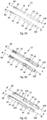
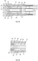
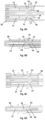
- Figs. 8A to 8F show cross-sectional top views and a cross-sectional side views of further embodiments of the connector assembly 110 in which the insulating element 28 comprises at least one protrusion 52 and at least one recess 54 for each inner signal contact 12.
- the at least one respective inner signal contact 12 also comprises at least one protrusion 56 and at least one recess 58, respectively.
- the at least one protrusion 52 of the insulating element 28 engages with the at least one recess 58 of the inner signal contact 12, and vice versa.
- the protrusions 52, 56 and the recesses 54, 58 are configured to cooperate in order to substantially prevent a rotation and/or an axial movement of the inner signal contact 12 relative to the insulating element 28.
- the rotation and/or the axial movement of the inner signal contact 12 relative to the insulating element 28 is reduced, or minimized, or limited to some degree, such that only an insignificant amount of rotation and axial movement of the inner signal contact 12 relative to the insulating element 28 may occur.
- the insulating element 28 may comprise two protrusions 52 for each inner signal contact 12, wherein one protrusion 52 of the insulating element 28 is arranged in front of the protrusion 56 of the inner signal contact 12 and one protrusion 52 of the insulating element 28 is arranged behind the protrusion 56 of the inner signal contact 12, as shown in Figs. 8A to 8C .
- the protrusion 52 of the insulating element 28 arranged in front of the protrusion 56 of the inner signal contact 12 may act as a forward stop or a backward stop and the protrusion 52 of the insulating element 28 arranged behind the protrusion 56 of the inner signal contact 12 may act as a backward stop.
- a forward stop may reduce or even prevent an axial movement of the at least one elongated inner signal contact 12 relative to the insulating element 28 in a forward direction, i.e. in a direction towards the funnel-shaped end section 30 of the inner signal contact 12.
- a backward stop may reduce or even prevent an axial movement of the at least one elongated inner signal contact 12 relative to the insulating element 28 in a backward direction, i.e. in a direction towards the second connection portion 18 of the inner signal contact 12.
- Fig. 9A shows a perspective view of a part of an insulating element 28 having two inner signal contacts 12 wherein each inner signal contact 12 comprises a hole 62 defined to receive a corresponding control element 60 of the insulating element 28.
- the control elements 60 are arranged such that they engage with the holes 62 when the connector assembly 110 is correctly assembled, i.e. when the inner signal contacts 12 are correctly embedded in the insulating element 28.
- Figs. 9B and Fig. 9C show the control elements 60 inserted into the holes 62 of U-shaped signal contact portions 50 of the inner signal contacts 12. It is to be understood that the holes 62 and, thus, the control elements 60 may also be arranged at other parts of the inner signal contacts 12.
- the control elements 60 are visible in the holes 62 of the inner signal contacts 12 when the inner signal contacts 12 reach an end-position during the assembling of the connector assembly 110. Thus, a visual control of the end-position of the inner signal contacts 12 is possible when the inner signal contacts 12 are mounted in the insulating element 28.
- Figs. 10A and 10B show an insulating element 28 according to a further embodiment.
- the insulation element 28 comprises at least one clamping element 48 in each cavity 32, which is configured to secure the wire insulation 20 of a cable 22 (not shown) and/or a conductor 21 to which the respective inner signal contact 12 is connected.
- a gap defined by two opposing clamping elements 48 is less than a main diameter of the wire insulation 20 or the conductor 21.
- Fig. 11A shows a perspective view of a part of the insulating element 28 having two inner signal contacts 12 according to a further embodiment.
- the inner signal contacts 12 each comprise a termination element 24, for example, a pair of crimping wings, arranged at the second connection portion 18, wherein the termination element 24 may be configured to secure a wire insulation 20 or a conductor 21, e.g. a conductor, in the inner signal contact 12.
- the insulating element 28 comprises at least one retaining element 64 for each inner signal contact 12, which is configured to secure at least one of the respective termination element 24, the respective wire insulation 20, the conductor 21 and a respective signal contact portion 50 in the insulating element 28.
- Each retaining element 64 may be designed as a snap arm, wherein two opposing retaining elements 64 may form a cavity that is configured to hold or secure the termination element 24 or the wire insulation 20.
- Fig. 11B shows another embodiment of a part of an insulating element 28 in which the retaining element 64 is designed as a bracket that encloses at least one of the termination element 24, the wire insulation 20, the conductor 21 and the signal contact 50.
- the shape of the bracket may be adapted to the contour of the received element.
- the bracket may define circular cavities to receive the signal contact portions 50 of the inner signal contacts 12.
- Fig. 12A shows a cross-sectional view of a further embodiment of a first insulating part 28a having two inner signal contacts 12 in a partly assembled state.
- the first insulating part 28a may be radially mounted to the inner signal contacts 12.
- the inner signal contacts 12, in particular the signal contact portions 50 are pinched into the first insulating part 28a in a fully assembled state of the connector assembly 110.
- the signal contact portions 50 may have a greater cross-sectional dimension than respective cavities 66 of the first insulating part 28a ( Fig. 12A ).
- the cross-sectional dimension of the signal contact portions 50 is reduced to a cross-sectional dimension of the cavity 66 as shown in Fig. 12B . Furthermore, due to the reduction of the cross-sectional dimension of the signal contact portions 50, the wire insulations 20 or the conductors 21 attached to the inner signal contacts 12 are secured in the signal contact portions 50.
- the second insulating part 28b of the insulating element 28 may then be axially slid onto the inner signal contacts 12 in a direction of the first centre axis 98 defined by the inner signal contacts 12 such that the inner signal contacts 12 are fully enclosed by the first insulating part 28a and the second insulating part 28b.
- the inner signal contacts 12 may be inserted into the second insulating part 28b as shown in Fig. 12C . More specifically, Fig. 12C shows the inner signal contacts 12 in their final position in the second insulation part 28b, but not yet in their fully assembled state since the first insulating part 28a is still to be mounted. Thus, one elongated inner signal contact 12 is pinched into the first insulating part 28a by radially mounting the first insulating part 28a in respect of the at least one elongated inner signal contact 12 and the second insulating part 28b, as shown in Fig. 12D .
- the cross-sectional dimension of the signal contact 50 is reduced to a cross-sectional dimension of the cavity 66 by pressing the first insulating part 28a onto the signal contact 50.
- the inner signal contact 12, in particular the signal contact 50 is pinched into the first insulating part 28a as shown in Fig. 12 D in a fully assembled state of the connector assembly 110.
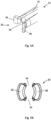
- Figs. 13A to 13C and 14A to 14C show two embodiments of a first insulating part 28a having two press fit elements 68.
- the press fit elements 68 may be formed as cuboidal elements having protrusions 74 that protrude over the surfaces of the cuboidal elements, as shown in Figs. 13A and 14A .
- Respective elements of the second insulating part 28b may be formed as cuboidal recesses 76 configured to receive the press fit elements 68 of the first insulating part 28a.
- a cross-sectional dimension of the cuboidal recesses 76 may be substantially the same as a cross-sectional dimension of the corresponding press fit elements 68 (the protrusions 74 not considered).
- the press fit elements 68 are inserted into the corresponding cuboidal recesses 76.
- the press fit elements 68 are secured in the recesses 76 by means of the protrusions 74. More specifically, the press fit elements 68 have to be pressed into the recesses 76 since the protrusions 74 lead to a cross-sectional dimension of the press fit elements 68 greater than that of the recesses 76.
- either radial forces 70 ( Fig. 13C ) or axial forces 72 ( Fig. 14C ) act between the first insulating part 28a, in particular the press fit elements 68, and the second insulating part 28b.
- a first insulating part 28a has at least one locking element 78.
- the locking element 78 may be formed as a cuboidal element having a mushroom head 79 ( Figs. 15A, 15C ) or having a Y-shaped or forked head 81 ( Figs.16A, 16C ).
- the second insulating part 28b comprises a matching substantially cuboidal locking recess 80 configured to receive the locking element 78 of the first insulating part 28a.
- the locking recess 80 may comprise a first recess part 80a and a second recess part 80b, as shown in Figs. 15C and 16C .
- a cross-sectional dimension of the first recess part 80a may be substantially the same as a cross-sectional dimension of the cuboidal locking element 78, i.e. the cuboidal locking element 78 fits into the first recess part 80a.
- a maximum outer cross-sectional dimension of the mushroom head 79 or the fork head 81 is greater than the cross-sectional dimension of the first recess part 80a.
- a cross-sectional dimension of the second recess part 80b of the locking recess 80 is greater than the maximum outer cross-sectional dimension of the mushroom head 79 or the forked head 81 and, thus, also greater than the first recess part 80a such that the first recess part 80a and the second recess part 80b of the locking recess 80 define a shoulder 82 at their transition ( Figs. 15C and 16C ).
- the locking element 78 is fully inserted into the locking recess 80, the mushroom head 79 or the forked head 81 sits on the shoulder 82 and thereby secures the first insulating part 28a to the second insulating part 28b ( Figs. 15C and 16C ).
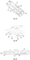
- Fig. 17A shows an embodiment of a first insulating part 28a and a second insulating part 28b having a locking pin 84 and a locking slot 86, respectively, in a partly assembled state of the connector assembly 110.
- the locking slot 86 is configured to receive the locking pin 84.
- the locking slot 86 comprises a first slot part 86a and a second slot part 86b.
- a cross-sectional dimension of the first slot part 86a of the locking slot 86 may be substantially the same as a cross-sectional dimension of the locking pin 84, i.e. the locking pin 84 fits into the first slot part 86a of the locking slot 86 ( Fig. 17A ).
- a cross-sectional dimension of the second slot part 86b is greater than the cross-sectional dimension of the locking pin 84 such that the first slot part 86a and the second slot part 86b define a shoulder 90 ( Fig. 17B ).
- the locking slot 86 may be similar to the locking recess 80 described above.
- the punch tool 88 presses on to a free end of the locking pin 84 such as to deform the free end of the locking pin 84 into a mushroom head that sits on the shoulder 90, thereby securing the first insulating part 28a to the second insulating part 28b ( Fig. 17B ).
- the locking pin 84 may be deformable in a cold or a hot state, i.e. the locking pin 84 is deformable by means of the punch tool 88 with or without preheating the locking pin 84 or the punch tool 88.
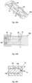
- Fig. 18A shows a first insulating part 28a having two tongues 96.
- the second insulating part 28b comprises corresponding grooves 94 in which the tongues 96 can be received.
- the first insulating part 28a is secured to the second insulating part 28b by inserting the tongues 96 into their associated grooves 94 and axially sliding the first insulating part 28a relative to the second insulating part 28b in a direction of the centre axes 98 defined by the inner signal contacts 12.
- Figs. 18B and 18C show a cross-sectional view of one of the tongues 96 inserted into its associated groove 94.
- a maximum outer dimension of the tongue 96 may be substantially the same as a maximum inner dimension of the groove 94, i.e.
- the tongue 96 may fit into the groove 94.
- the maximum outer dimension of the tongue 96 may be somewhat greater than the maximum inner dimension of the groove 94. Therefore, the tongue 96 has to be forced into the groove 94 and is somewhat deformed when fully inserted into the groove 94.
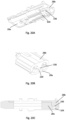
- Figs. 19A, 19B and 20A - 20C show two embodiments of an insulating element 28 in which a first insulating part 28a comprises a locking cavity 104 and a second insulating part 28b comprises a locking protrusion 106 to be received in the locking cavity 104.
- the locking protrusion 106 extends into the locking cavity 104 when the connector assembly 110 is correctly assembled.
- Figs. 21A and 21B depict a process of assembling a collector assembly 110 having an insulating element 28 as described in connection with Figs. 14A to 14C .
- conductors 21 of a cable 22 are connected to the inner signal contacts 12 by attaching the wire insulations 20 to the inner signal contacts 12 by means of a termination element 24, for example, crimping wings.
- a first insulating part 28a is then radially mounted to the inner signal contacts 12 such that the inner signal contacts 12 are embedded in cavities 32 of the first insulating part 28a.
- the first insulation part 28a is axially slid into position along the inner signal contacts 12 in a direction of the centre axes 98 defined by the inner signal contacts 12 ( Fig. 21B ).
- funnel-shaped end sections 30 of the inner signal contacts 12 are optionally widened by means of ribs 46, if ribs 46 are arranged in a front opening 40 of the first insulation part 28a, as described above.
- a second insulating part 28b is radially mounted to the inner signal contacts 12 and secured to the first insulating part 28a ( Fig. 21C ) as described above.
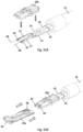
- Figs. 22A and 22B depict an alternative process of assembling a connector assembly 110 as described herein.
- conductors 21 of a cable 22 are connected to the inner signal contacts 12 by attaching the wire insulations 20 to the inner signal contacts 12 by means of a termination element 24, for example crimping wings.
- a second insulating part 28b is then radially mounted to the inner signal contacts 12 such that the inner signal contacts 12 are embedded in cavities 32 of the second insulating part 28b ( Figs. 22A ).
- a first insulating part 28a is mounted to the second insulating part 28b, as shown in Fig. 22B .
- the first insulation part 28a is axially slid onto the inner signal contacts 12 in a direction of the centre axes 98 defined by the inner signal contacts 12.
- funnel-shaped end sections 30 of the inner signal contacts 12 enter front openings 40 of the first insulating part 28a and are optionally widened by means of ribs 46, if ribs 46 are arranged in the front openings 40, as described above.
- the first insulating part 28a is secured to the second insulation part 28b by means as described above, for example, by means of tongues 96 and grooves 94.
- Figs. 23A to 23C depict another process of assembling a collector assembly 110, in particular for inner signal contacts 12 having welding openings 26 to connect the inner signal contacts 12 to conductors 21 of a cable 22 via welding, e.g. laser, ultrasonic or resistance welding.
- Fig. 23A shows a step of inserting inner signal contacts 12 into a first insulating part 28a.
- the inner signal contacts 12 are axially slid into cavities 32 of the first insulating part 28a in a direction of the centre axes 98 defined by the inner signal contacts 12.
- the inner signal contacts 12 may be secured in the first insulating part 28a by features as described above, for example, by means of hooks 103.
- a step of attaching conductors 21 of a cable 22 to the inner contacts 12 follows, as shown in Fig. 23B .
- the conductors 21 are connected to the inner signal contacts 12 via laser welding or ultrasonic welding or resistance welding in the welding openings 26.
- a second insulating part 28b is attached to the first insulating part 28a ( Fig. 23C ). More specifically, the second insulating part 28b is radially mounted to the inner signal contacts 12 and the first insulating part 28a. Therein, the second insulation part 28b is secured to the first insulating part 28a by means as described above.
Landscapes
- Connector Housings Or Holding Contact Members (AREA)
Abstract
Description
- The present disclosure relates to a connector assembly, preferably for multi GHz applications. In particular, the disclosure relates to an H-MTD® (High Speed Modular Twisted-Pair-Data) connector assembly.
- The so called H-MTD® system has been established by a company called "Rosenberger Hochfrequenztechnik GmbH & Co. KG". Applications for the H-MTD® system are 4K camera systems, autonomous driving, radar, lidar, high-resolution displays and rear seat entertainment. Connectors of said system are meant to allow data transmission up to 15 GHz or 20 Gbps while having a small package size.
- In such high-speed applications, every tenth of a millimeter of the interconnection channel and of the signal connectors should be within a certain data transmission (differential) impedance bandwidth (typical 100 +/- 5 Ω) and should be matched to preceding and succeeding sections. To this end, in each of these sections, metal portions of an inner contact or signal contact and an outer contact or shielding, insulating material of an insulating element and any air gaps must be balanced in size and position with respect to each other. However, there is also a need for these components to meet other non-signal-integrity requirements, in particular mechanical requirements. For example, it has to be ensured that a male signal contact is always correctly guided into a corresponding female signal contact. To achieve high data transmission, an optimum electrical and mechanical connection between a male signal contact and a female signal contact is indispensable.
- Accordingly, there is a need to provide a connector assembly of the H-MTD® kind that enables a more accurate connection between male and female signal contacts.
- This demand is satisfied by a connector assembly according to claim 1.
- The present disclosure provides a connector assembly according to claim 1. Embodiments can be taken from the dependent claims, the description and the drawings.
- In one aspect, the present disclosure is directed at a connector assembly, wherein the connector assembly comprises at least one elongated inner signal contact having a first connection portion, wherein the first connection portion comprises a tube-like main section and a funnel-shaped end section; and an insulating element, wherein the insulating element defines at least one elongated cavity designed to accommodate the elongated inner signal contact, wherein a maximum outer cross-sectional dimension of the funnel-shaped end section is greater than a minimum cross-sectional dimension of the elongated cavity.
- The connector assembly may be configured for high speed data transmission. In particular, the connector assembly may be of the H-MTD® type for automotive applications.
- The connector assembly described herein is a female connector assembly, i.e. the inner signal contact is a female signal contact. The inner signal contact has a funnel-shaped end section allowing for pin movement, i.e. allowing insertion of a male signal contact pin.
- The inner signal contact is embedded in an insulating element which may form a one-part housing or a multi-part housing, in particular a two-part housing. More specifically, the insulating element may define a cavity having a first cavity portion which receives the tube-like main section of the inner signal contact, and a second cavity portion which receives the funnel-shaped end section of the inner signal contact. A cross-sectional dimension of the first cavity portion, also referred to as a minimum cross-sectional dimension of the cavity, and an outer cross-sectional dimension of the tube-like main section may be substantially equal, i.e. the tube-like main section may be embedded in the first cavity portion with marginal clearance between the tube-like main section and the insulating material defining the first cavity portion.
- Since the inner signal contact expands or flares in a direction away from the tube-like main section to form the funnel-shaped end section, a maximum outer cross-sectional dimension of the funnel-shaped end section is greater than the outer cross-sectional dimension of the tube-like main section. Consequently, the maximum outer cross-sectional dimension of the funnel-shaped end section is also greater than the cross-sectional dimension of the first cavity portion, i.e. the minimum cross-sectional dimension of the cavity, thereby making it generally impossible for the inner signal contact to be pushed along the length of the cavity.
- It is to be understood that in order to be able to accommodate the funnel-shaped end section of the inner signal contact, the cross-sectional dimension of the second cavity portion, also referred to as a maximum cross-sectional dimension of the cavity, must at least correspond to the maximum outer cross-sectional dimension of the funnel-shaped end section and as such is also greater than the minimum cross-sectional dimension of the cavity.
- According to an embodiment, the funnel-shaped end section may comprise a first end section part and a second end section part, wherein the first end section part and the second end section part are separated by two air gaps. The air gaps may be diagonally arranged, i.e. the two air gaps are arranged opposite from each other. The first end section and the second end section of the funnel-shaped end section allow a spreading apart of the funnel-shaped end section to thereby make the insertion of a male signal contact pin easier. According to another embodiment, the funnel-shaped end section may be a machined end section or a stamped, rolled, or bended end section, in which a first end section part and a second end section part are separated by just one small slit.
- According to an embodiment, the insulating element may comprise at least one front opening configured to receive the funnel-shaped end section, and two chamfers protruding into the air gaps such that the first end section part, the second end section part and the two chamfers define an inlet. In other words, the chamfers may radially protrude into the front opening. The two chamfers may be arranged diagonally to each other.
- The front opening of the insulating element may be configured to receive a male signal contact, and the inlet serves to lead the male signal contact into the female inner signal contact of the connector assembly. The inlet may provide an at least approximately 360° lead-in cone to guide the male signal contact into the tube-like main section of the female inner signal contact. Thus, an incorrect connection of the signal contacts can be prevented which may occur by inserting the male signal contact past the inner signal contact. Furthermore, damage to at least one of the male signal contact, the inner signal contact and the insulating element may be avoided.
- According to an embodiment, the funnel-shaped end section comprises a first end section part and a second end section part, wherein the first end section part and the second end section part are separated by two air gaps, and wherein the insulating element comprises at least one rib engaging one of the air gaps and thereby widening the funnel-shaped end section. By widening the funnel-shaped end section the size of the inlet may be maximized. The two air gaps may be arranged diagonally to each other.
- According to an embodiment, the insulating element and the at least one elongated inner signal contact may comprise at least one protrusion and at least one recess, respectively, wherein the protrusion and the recess are configured to cooperate in order to at least reduce or even prevent a rotation and/or an axial movement of the at least one elongated inner signal contact relative to the insulating element. The at least one protrusion may be a blocking element that provides a forward stop and/or a backward stop for the at least one elongated inner signal contact in the insulating element. A precise rotational control and limitation of movement of the inner signal contact as well as a precise rigid back and forward stop of the inner signal contact may thus be achieved.
- According to an embodiment, the insulating element may comprise a control element and the at least one elongated inner signal contact may comprise a hole receiving the control element when the connector assembly is correctly assembled. The control element may be visible in the hole of the at least one elongated inner signal contact when the at least one elongated inner signal contact reaches its correct end-position during assembling. Thus, easy visual confirmation of a correct assembly of the at least one elongated inner signal contact in the insulating element is possible.
- According to an embodiment, the insulating element may comprise at least one clamping element configured to secure a wire to which the at least one elongated inner signal contact is connected.
- According to an embodiment, the at least one elongated inner signal contact may comprise a termination element configured to receive a wire and the insulating element may comprise at least one retaining element configured to secure the termination element and/or the wire in the insulating element. The termination element may comprise a pair of crimping wings or any other suitable termination means.
- According to another embodiment, the insulating element may comprise a first insulating part and a second insulating part, wherein the first insulating part and the second insulating part together surround the at least one inner signal contact. The terms "first" and "second" are only used to differentiate the two insulation parts. There is no restriction to features concerning the first insulating part or the second insulating part, i.e. all features of the first insulating part may be also features of the second insulating part.
- According to an embodiment, one of the first insulating part and the second insulating part may be configured to be radially mounted in respect of the at least one elongated inner signal contact and the respective other one of the first insulating part and the second insulating part is configured to be axially slid onto the at least one elongated inner signal contact.
- According to an embodiment, the at least one elongated inner signal contact may be pinched into the first insulating part or the second insulating part.
- According to an embodiment, the first insulating part or the second insulating part may comprise a press fit element configured to secure the first insulating part to the second insulating part.
- According to an embodiment, the first insulating part or the second insulating part may comprise at least one locking element configured to snap fit the first insulating part and the second insulating part together and thereby secure the first insulating part to the second insulating part. The locking element may provide a passive lock and/or an active lock.
- According to an embodiment, the first insulating part or the second insulating part may comprise a pin and the respective other one of the first insulating part and the second insulating part comprises a slot, wherein the slot is configured to receive the pin and the pin is deformed and secured in the slot to thereby secure the first insulating part to the second insulating part.
- According to an embodiment, the first insulating part or the second insulating part may comprise a groove and the respective other one of the first insulating part and the second insulating part may comprise a tongue received in the groove.
- According to an embodiment, the first insulating part or the second insulating part may comprise a locking cavity and the respective other one of the first insulating part and the second insulating part may comprise a locking protrusion received in the locking cavity.
- Exemplary embodiments and functions of the present disclosure are described herein in conjunction with the following drawings showing:
- Fig. 1
- an exploded view of a connector;
- Fig. 2A
- a perspective view of a connector assembly according to an embodiment of the present disclosure;
- Fig. 2B
- an exploded view of the connector assembly of
Fig. 2A ; - Fig. 3A
- a perspective view of inner signal contacts according to an embodiment of the present disclosure;
- Fig. 3B
- a perspective view of inner signal contacts according to another embodiment of the present disclosure;
- Fig. 3C
- a perspective view of inner signal contacts according to another embodiment of the present disclosure;
- Fig. 4A
- a cross-sectional view of the connector assembly in a partly assembled state;
- Fig. 4B
- a cross-sectional view of the connector assembly in a fully assembled state;
- Fig. 5A
- a perspective view of a funnel-shaped end section of an inner signal contact;
- Fig. 5B
- a cross-sectional view of the funnel-shaped end section;
- Fig. 6A
- a perspective view of front openings of an insulating element;
- Fig. 6B
- a front view of the front openings having inner signal contacts;
- Fig. 6C
- a front view of an inlet opening defined by the inner signal contacts;
- Fig. 7A
- a perspective view of a part of an insulating element having inner signal contacts in a partly assembled state;
- Fig. 7B
- a cross-sectional view of the part of the insulating element having the inner signal contacts in the partly assembled state;
- Fig. 7C
- a perspective view of the part of the insulating element having inner signal contacts in a fully assembled state;
- Fig. 7D
- a cross-sectional view of the part of the insulating element having inner signal contacts in the fully assembled state;
- Fig. 8A
- a cross-sectional top view of a connector assembly;
- Fig. 8B
- a cross-sectional side view of the connector assembly of
Fig. 8A ; - Fig. 8C
- a cross-sectional top view of a connector assembly according to another embodiment;
- Fig. 8D
- a cross-sectional side view of the connector assembly of
Fig. 8C ; - Fig. 8E
- a cross-sectional top view of a connector assembly according to another embodiment;
- Fig. 8F
- a cross-sectional side view of the connector assembly of
Fig. 8E ; - Fig. 9A
- a perspective view of a part of an insulating element having inner signal contacts;
- Fig. 9B
- a perspective cross-sectional view of the part of the insulating element having inner signal contacts;
- Fig. 9C
- a cross-sectional side view of the part of the insulating element having inner signal contacts;
- Fig. 10A
- a perspective view of a part of an insulating element according to a further embodiment of the present disclosure;
- Fig. 10B
- a cross-sectional top view of the part of the insulating element having wires;
- Fig. 11A
- a perspective view of a part of a further embodiment of an insulating element having inner signal contacts;
- Fig. 11B
- a perspective view of a part of a further embodiment of an insulating element;
- Fig. 12A
- a cross-sectional view of a first embodiment of a first insulating part having inner signal contacts in a partly assembled state;
- Fig. 12B
- a cross-sectional view of the first embodiment of the first insulating part having inner signal contacts in a fully assembled state;
- Fig. 12C
- a cross-sectional view of a second embodiment of a second insulating part having the inner signal contacts in a final position, but not yet in a fully assembled state;
- Fig. 12D
- a cross-sectional view of the second embodiment of the first insulating part having the inner signal contacts in a fully assembled state;
- Fig. 13A
- a perspective view of a first embodiment of a first insulating part having two press-fit elements;
- Fig. 13B
- a cross-sectional top view of the first insulating part;
- Fig. 13C
- a cross-sectional view of one of the press-fit elements engaging a second insulating part;
- Fig. 14A
- a perspective view of a second embodiment of a first insulating part having two press-fit elements;
- Fig. 14B
- a cross-sectional top view of the first insulating part;
- Fig. 14C
- a cross-sectional view of one of the press-fit elements engaging a second insulating part;
- Fig. 15A
- a perspective view of a first insulating part having a locking element according to a first embodiment;
- Fig. 15B
- a cross-sectional top view of the first insulating part;
- Fig. 15C
- a cross-sectional view of the locking element engaging a second insulating part;
- Fig. 16A
- a perspective view of a first insulating part having a locking element according to a second embodiment;
- Fig. 16B
- a cross-sectional top view of the first insulating part;
- Fig. 16C
- a cross-sectional view of the locking element engaging a second insulating part;
- Fig. 17A
- a perspective view of a first insulating part having a pin and a second insulating part having a slot in a partly assembled state;
- Fig. 17B
- a perspective view of the first insulating part and the second insulating part in a fully assembled state;
- Fig. 18A
- a perspective view of a first insulating part having two tongues;
- Fig. 18B
- a cross-sectional view of the first insulating part and a second insulating part showing one of the tongues in a corresponding groove of the second insulating part;
- Fig. 18C
- an enlargement of the tongue in the groove;
- Fig. 18D
- a cross-sectional view of a first insulating part having a tongue and a second insulating part having a groove according to an alternative embodiment;
- Fig. 18E
- an enlargement of the tongue in the groove;
- Fig. 19A
- a perspective view of a first insulating part and a second insulating part according to a further embodiment;
- Fig. 19B
- a cross-sectional view of the first insulating part and the second insulating part;
- Fig. 20A
- a perspective view of a first insulating part and a second insulating part;
- Fig. 20B
- a perspective cross-sectional view of the first insulating part and the second insulating part;
- Fig. 20C
- a cross-sectional side view of the first insulating part and the second insulating part;
- Fig. 21A
- a first step of mounting a first insulating part to inner signal contacts;
- Fig. 21B
- a second step of mounting the first insulating part to the inner signal contacts;
- Fig. 21C
- a step of mounting a second insulating part to the assembly of the first insulating part and the inner signal contacts;
- Fig. 22A
- a step of mounting a second insulating part to inner signal contacts;
- Fig. 22B
- a step of mounting a first insulating part to the assembly of the second insulating part and the inner signal contacts;
- Fig. 23A
- a step of inserting inner signal contacts into a first insulating part;
- Fig. 23B
- a step of attaching wires to the inner signal contacts;
- Fig. 23C
- a step of attaching a second insulating part to the assembly of the first insulating part and the inner signal contacts.
-
Fig. 1 depicts an exploded view of aconnector 10, in particular a female connector, comprising two elongatedinner signal contacts 12 arranged generally parallel to each other along anaxial direction 14 of theconnector 10. Thesignal contacts 12 have afirst connection portion 16 for connecting theconnector 10 to a mating connector, in particular a male connector, and asecond connection portion 18 for connecting thesignal contacts 12 torespective conductors 21 of acable 22. Theconductors 21 may be strands. Furthermore, theconductors 21 may be embedded in awire insulation 20. Thesecond connection portion 18 may include atermination element 24 comprising, for example, two crimping wings (shown inFigs. 3A and 3B ) or may have a welding portion having a welding opening 26 (shown inFig. 3C ). Thewelding opening 26 may be used to connect thesignal contacts 12 torespective conductors 21 of thecable 22 via laser welding or ultrasonic welding. Alternatively, resistance welding can be used to connect thesignal contacts 12 torespective conductors 21 of thecable 22. - The
inner signal contacts 12 are arranged in an insulatingelement 28 which may form a di-electric housing. In the embodiment shown inFig. 1 , the insulatingelement 28 comprises two separate insulating parts, a first insulatingpart 28a and a secondinsulating part 28b, which together enclose theinner signal contacts 12. The firstinsulating part 28a and the second insulatingpart 28b may be attached to each other, for example, by a click-on connection, i.e. by a snap fit engagement. It is to be understood that the first insulatingpart 28a and the second insulatingpart 28b may be attached to each other by other suitable connections, as will be described further below. Furthermore, it is to be understood that the insulatingelement 28 may also be a one-part insulating element 28, for example, produced by injection molding, i.e. by overmolding theinner signal contacts 12. In such an insulatingelement 28, undesirable air pockets may be minimized. - The first
insulating part 28a fulfills the task of locking thesignal contacts 12 in theaxial direction 14 so that theinner signal contacts 12 maintain their axial position when theconnector 10 is connected to a mating connector. It is to be understood that, additionally or alternatively, the second insulatingpart 28b may fulfill the task of locking thesignal contacts 12 in theaxial direction 14. - The
connector 10 further comprises afirst shielding part 31 and asecond shielding part 33 both formed as half shells which together form anouter shielding contact 35. Theouter shielding contact 35 surrounds theinner signal contacts 12 and the insulatingelement 28 to provide a shield against interfering signals. However, theouter shielding contact 35 can also be used as an electrical conductor to transport electric power. At adistal end 37 of theconnector 10, theconnector 10 comprises multiple shieldingcontacts 39. At aproximal end 41 of theconnector 10, the first shieldingpart 31 forms acover 43. Thesecond shielding part 33 forms a crimpingportion 45 at theproximal end 41 of theconnector 10 to mechanically and electrically connect theouter shielding contact 35 to thecable 22. Furthermore, theconnector 10 comprises aninner crimp ferrule 47 which is placed around thecable 22. - The
inner signal contacts 12 and the insulatingelement 28 together form aconnector assembly 110 according to an embodiment of the present disclosure, as shown inFig. 2A. Fig. 2B shows an exploded view of theconnector assembly 110. -
Figs. 3A, 3B and 3C depict a perspective view of theinner signal contacts 12 according to various embodiments. Theinner signal contacts 12 generally extend parallel to one another. Eachinner signal contact 12 has afirst connection portion 16 for connecting thesignal contact 12 to a mating signal contact and asecond connection portion 18 for connecting thesignal contact 12 to arespective conductor 21 of a cable 22 (Fig. 1 ). Thefirst connection portion 16 has a tube-likemain section 29 defining afirst centre axis 98 and a funnel-shapedend section 30, wherein the tube-likemain section 29 may have a round, in particular a generally circular or oval, or a polygonal cross-section. Thesecond connection portion 18 defines asecond centre axis 100 where a centre axis of thecable 22 is placed at. A distance A between the centre axes 98 of thefirst connection portions 16 may be equal or larger than a distance B between the centre axes 100 of thesecond connection portions 18. Alternatively, a distance A between the centre axes 98 of thefirst connection portions 16 may be smaller than a distance B between the centre axes 100 of thesecond connection portions 18. In other words, theinner signal contacts 12 may be formed so that a pitch translation may be generated. Each of theinner signal contacts 12 may be formed so that thefirst centre axis 98 is spaced apart in parallel from thesecond centre axis 100. - In another embodiment, shown in
Fig. 3C , theinner signal contacts 12 differ from theinner signal contacts 12 ofFigs. 3A and 3B in that hooks 103 are formed at side surfaces of thefirst connection portions 16. Thehooks 103 help to axially fix theinner signal contacts 12 in the insulatingelement 28. - The
second connection portions 18 of theinner signal contacts 12 may comprise welding openings 26 (Fig. 3C ) that are arranged to allow, for example, a laser beam to weld aconductor 21 to theinner signal contacts 12. Alternatively,termination elements 24 can be formed at thesecond connection portions 18 so that theinner signal contacts 12 can be attached onto the wires insulating 20 of the cable 22 (Figs. 3A and 3B ). - The
inner signal contacts 12 may comprisesignal contact portions 50. In one embodiment, thesignal contact portions 50 may have an oval cross-section, as shown inFig. 3A . In another embodiment thesignal contact portions 50 may have a U-shaped cross-section, as shown inFig. 3B . In yet another embodiment, thesignal contact portions 50 may have a circular cross-section, as shown inFig. 3C . It is to be understood, that the shape of thesignal contact portions 50 is not limited to the shapes shown inFigs. 3A to 3C . Rather, thesignal contact portions 50 may be of any suitable shape. Thesignal portions 50 may be configured to at least reduce or even prevent a rotation and/or an axial movement of the at least one elongatedinner signal contact 12 relative to the insulatingelement 28. Thesignal portions 50 may be defined as blocking elements that provide a forward stop and/or a backward stop for the at least one elongatedinner signal contact 12 in the insulatingelement 28. A precise rotational control and limitation of movement of theinner signal contact 12 as well as a precise rigid back and forward stop of theinner signal contact 12 may thus be achieved. Thesignal portions 50 may also be configured to receive awire insulation 20. -
Figs. 4A and 4B show cross-sectional views of aconnector assembly 110 in a partly assembled state (Fig. 4A ) and in a fully assembled state (Fig. 4B ). Theconnector assembly 110 comprises at least one elongatedinner signal contact 12, in the present embodiment twoinner signal contacts 12. Eachinner signal contact 12 comprises afirst connection portion 16 having a tube-likemain section 29 and a funnel-shapedend section 30. The tube-likemain section 29 may have a round, in particular a generally circular or oval, or a polygonal cross-section. The funnel-shapedend section 30 expands from one end of the tube-likemain section 29 such that a maximum outer cross-sectional dimension C of the funnel-shapedend section 30 is greater than a maximum outer cross-sectional dimension of the tube-likemain section 29. - The at least one elongated
inner signal contact 12 is accommodated in anelongated cavity 32 of the insulatingelement 28. A first part of thecavity 32 is designed to generally form fittingly receive the tube-likemain section 29, i.e. a cross-sectional dimension of the first part of thecavity 32 is generally equal to the outer cross-sectional dimension of the tube-likemain section 29, and a second part of thecavity 32 makes room for the funnel-shapedend section 30. In other words, a cross-sectional dimension D of the first part of thecavity 32, also referred to as a minimum cross-sectional dimension D of thecavity 32, corresponds to the outer cross-sectional dimension of the tube-likemain section 29, whereas a cross-sectional dimension of the second part of thecavity 32, also referred to as a maximum cross-sectional dimension of thecavity 32, is at least equal to or greater than the maximum outer cross-sectional dimension C of the funnel-shapedend section 30. Since the maximum outer cross-sectional dimension C of the funnel-shapedend section 30 is greater than the maximum outer cross-sectional dimension of the tube-likemain section 29, the maximum outer cross-sectional dimension C of the flaring funnel-shapedend section 30 is also greater than the cross-sectional dimension D of the first part of thecavity 32, i.e. the minimum cross-sectional dimension D of thecavity 32. It is to be understood that the dimensions described herein may be diameters if the tube-likemain section 29 and thecavity 32 are of circular cross-section. -
Figs. 5A and 5B show a perspective view and a cross-sectional view, respectively, of the funnel-shapedend section 30 of theinner contact 12. The funnel-shapedend section 30 comprises a firstend section part 36 and a secondend section part 38. The firstend section part 36 and the secondend section part 38 are separated by twoair gaps 34, i.e. there is a clearance between the firstend section part 36 and the secondend section part 38. The firstend section part 36 and the secondend section part 38 may be diagonally arranged, i.e. arranged opposite from each other. Accordingly, the twoair gaps 34 may be diagonally arranged, i.e. arranged opposite from each other. - As shown in
Figs. 6A to 6C , eachcavity 32 ends in afront opening 40 of theinsulation element 28, which allows a mating contact to be connected to theinner contact 12 arranged in thecavity 32. Eachfront opening 40 is configured to receive the funnel-shapedend section 30 of theinner signal contact 12. Two, for example, diagonally arrangedchamfers 42 protrude into thefront opening 40 and, more specifically, into theair gaps 34 of the funnel-shapedend section 30 received in thefront opening 40. - When the funnel-shaped
end section 30 is received in thefront opening 40, the firstend section part 36, the secondend section part 38 and the twochamfers 42 together define aninlet 44 configured to correctly guide a matching male signal contact (not shown) into the femaleinner signal contact 12. Theinlet 44 may form a 360-degree lead-in cone, in particular having an at least substantially closed perimeter, to guide the male signal contact into theinner signal contact 12. Depending on the geometrical definition of theend section parts corresponding chamfers 42, the inlet may be of round, in particular circular or oval, or of polygonal cross-section. -
Figs. 7A and 7B show a part of the insulatingelement 28 havinginner signal contacts 12 in a partly assembled state of theconnector assembly 110. The insulatingelement 28 comprises at least onerib 46 in eachcavity 32, wherein therib 46 may be an extension of one of thechamfers 42 in a direction of thefirst centre axis 98 defined by the respectiveinner signal contact 12. Therib 46 engages one of theair gaps 34 when the funnel-shapedend section 30 of theinner signal contact 12 is inserted into thefront opening 40 and thereby widens the funnel-shapedend section 30. In a not fully assembled state (Figs. 7A and 7B ), the funnel-shapedend section 30 of theinner signal contact 12 is not in contact with therib 46 and, thus, in a relaxed state. -
Fig. 7C shows a perspective view andFig. 7D shows a cross-sectional view of the part of the insulatingelement 28 havinginner signal contacts 12 in a fully assembled state of theconnector assembly 110. When theinner signal contacts 12 are inserted into the insulatingelement 28, the funnel-shapedend section 30, in particular the firstend section part 36 and the secondend section part 38 are pushed apart by therib 46 as shown inFigs. 7C and 7D . -
Figs. 8A to 8F show cross-sectional top views and a cross-sectional side views of further embodiments of theconnector assembly 110 in which the insulatingelement 28 comprises at least oneprotrusion 52 and at least onerecess 54 for eachinner signal contact 12. The at least one respectiveinner signal contact 12 also comprises at least oneprotrusion 56 and at least onerecess 58, respectively. The at least oneprotrusion 52 of the insulatingelement 28 engages with the at least onerecess 58 of theinner signal contact 12, and vice versa. In other words, theprotrusions recesses inner signal contact 12 relative to the insulatingelement 28. More specifically, the rotation and/or the axial movement of theinner signal contact 12 relative to the insulatingelement 28 is reduced, or minimized, or limited to some degree, such that only an insignificant amount of rotation and axial movement of theinner signal contact 12 relative to the insulatingelement 28 may occur. - The insulating
element 28 may comprise twoprotrusions 52 for eachinner signal contact 12, wherein oneprotrusion 52 of the insulatingelement 28 is arranged in front of theprotrusion 56 of theinner signal contact 12 and oneprotrusion 52 of the insulatingelement 28 is arranged behind theprotrusion 56 of theinner signal contact 12, as shown inFigs. 8A to 8C . Theprotrusion 52 of the insulatingelement 28 arranged in front of theprotrusion 56 of theinner signal contact 12 may act as a forward stop or a backward stop and theprotrusion 52 of the insulatingelement 28 arranged behind theprotrusion 56 of theinner signal contact 12 may act as a backward stop. A forward stop may reduce or even prevent an axial movement of the at least one elongatedinner signal contact 12 relative to the insulatingelement 28 in a forward direction, i.e. in a direction towards the funnel-shapedend section 30 of theinner signal contact 12. A backward stop may reduce or even prevent an axial movement of the at least one elongatedinner signal contact 12 relative to the insulatingelement 28 in a backward direction, i.e. in a direction towards thesecond connection portion 18 of theinner signal contact 12. -
Fig. 9A shows a perspective view of a part of an insulatingelement 28 having twoinner signal contacts 12 wherein eachinner signal contact 12 comprises ahole 62 defined to receive acorresponding control element 60 of the insulatingelement 28. Thecontrol elements 60 are arranged such that they engage with theholes 62 when theconnector assembly 110 is correctly assembled, i.e. when theinner signal contacts 12 are correctly embedded in the insulatingelement 28.Figs. 9B and Fig. 9C show thecontrol elements 60 inserted into theholes 62 of U-shapedsignal contact portions 50 of theinner signal contacts 12. It is to be understood that theholes 62 and, thus, thecontrol elements 60 may also be arranged at other parts of theinner signal contacts 12. Thecontrol elements 60 are visible in theholes 62 of theinner signal contacts 12 when theinner signal contacts 12 reach an end-position during the assembling of theconnector assembly 110. Thus, a visual control of the end-position of theinner signal contacts 12 is possible when theinner signal contacts 12 are mounted in the insulatingelement 28. -
Figs. 10A and 10B show an insulatingelement 28 according to a further embodiment. Theinsulation element 28 comprises at least one clampingelement 48 in eachcavity 32, which is configured to secure thewire insulation 20 of a cable 22 (not shown) and/or aconductor 21 to which the respectiveinner signal contact 12 is connected. To secure thewire insulation 20 or theconductor 21 in the insulatingelement 28, a gap defined by two opposingclamping elements 48 is less than a main diameter of thewire insulation 20 or theconductor 21. Thus, thewire insulation 20 or theconductor 21 is clamped in the insulatingelement 28 when thewire insulation 20 or theconductor 21 is inserted into the gap. -
Fig. 11A shows a perspective view of a part of the insulatingelement 28 having twoinner signal contacts 12 according to a further embodiment. Theinner signal contacts 12 each comprise atermination element 24, for example, a pair of crimping wings, arranged at thesecond connection portion 18, wherein thetermination element 24 may be configured to secure awire insulation 20 or aconductor 21, e.g. a conductor, in theinner signal contact 12. The insulatingelement 28 comprises at least one retainingelement 64 for eachinner signal contact 12, which is configured to secure at least one of therespective termination element 24, therespective wire insulation 20, theconductor 21 and a respectivesignal contact portion 50 in the insulatingelement 28. Each retainingelement 64 may be designed as a snap arm, wherein two opposing retainingelements 64 may form a cavity that is configured to hold or secure thetermination element 24 or thewire insulation 20. -
Fig. 11B shows another embodiment of a part of an insulatingelement 28 in which the retainingelement 64 is designed as a bracket that encloses at least one of thetermination element 24, thewire insulation 20, theconductor 21 and thesignal contact 50. The shape of the bracket may be adapted to the contour of the received element. For example, the bracket may define circular cavities to receive thesignal contact portions 50 of theinner signal contacts 12. -
Fig. 12A shows a cross-sectional view of a further embodiment of a first insulatingpart 28a having twoinner signal contacts 12 in a partly assembled state. The firstinsulating part 28a may be radially mounted to theinner signal contacts 12. As shown inFig. 12B , theinner signal contacts 12, in particular thesignal contact portions 50, are pinched into the first insulatingpart 28a in a fully assembled state of theconnector assembly 110. To this end, thesignal contact portions 50 may have a greater cross-sectional dimension thanrespective cavities 66 of the first insulatingpart 28a (Fig. 12A ). By pressing thesignal contact portions 50 into thecavities 66, the cross-sectional dimension of thesignal contact portions 50 is reduced to a cross-sectional dimension of thecavity 66 as shown inFig. 12B . Furthermore, due to the reduction of the cross-sectional dimension of thesignal contact portions 50, thewire insulations 20 or theconductors 21 attached to theinner signal contacts 12 are secured in thesignal contact portions 50. The secondinsulating part 28b of the insulatingelement 28 may then be axially slid onto theinner signal contacts 12 in a direction of thefirst centre axis 98 defined by theinner signal contacts 12 such that theinner signal contacts 12 are fully enclosed by the first insulatingpart 28a and the second insulatingpart 28b. A detailed description of an assembly process will be described further below. - Alternatively, according to another embodiment, the
inner signal contacts 12 may be inserted into the second insulatingpart 28b as shown inFig. 12C . More specifically,Fig. 12C shows theinner signal contacts 12 in their final position in thesecond insulation part 28b, but not yet in their fully assembled state since the first insulatingpart 28a is still to be mounted. Thus, one elongatedinner signal contact 12 is pinched into the first insulatingpart 28a by radially mounting the first insulatingpart 28a in respect of the at least one elongatedinner signal contact 12 and the second insulatingpart 28b, as shown inFig. 12D . The cross-sectional dimension of thesignal contact 50 is reduced to a cross-sectional dimension of thecavity 66 by pressing the first insulatingpart 28a onto thesignal contact 50. Thus, theinner signal contact 12, in particular thesignal contact 50, is pinched into the first insulatingpart 28a as shown inFig. 12 D in a fully assembled state of theconnector assembly 110. -
Figs. 13A to 13C and14A to 14C show two embodiments of a first insulatingpart 28a having two pressfit elements 68. The pressfit elements 68 may be formed as cuboidalelements having protrusions 74 that protrude over the surfaces of the cuboidal elements, as shown inFigs. 13A and14A . Respective elements of the second insulatingpart 28b may be formed ascuboidal recesses 76 configured to receive the pressfit elements 68 of the first insulatingpart 28a. A cross-sectional dimension of thecuboidal recesses 76 may be substantially the same as a cross-sectional dimension of the corresponding press fit elements 68 (theprotrusions 74 not considered). When the first insulatingpart 28a and the second insulatingpart 28b are radially mounted to theinner signal contacts 12, the pressfit elements 68 are inserted into the corresponding cuboidal recesses 76. The pressfit elements 68 are secured in therecesses 76 by means of theprotrusions 74. More specifically, the pressfit elements 68 have to be pressed into therecesses 76 since theprotrusions 74 lead to a cross-sectional dimension of the pressfit elements 68 greater than that of therecesses 76. Depending on the arrangement of theprotrusions 74, either radial forces 70 (Fig. 13C ) or axial forces 72 (Fig. 14C ) act between the first insulatingpart 28a, in particular the pressfit elements 68, and the second insulatingpart 28b. - According to other embodiments shown in
Figs. 15A to 15C and16A to 16C , a first insulatingpart 28a has at least one lockingelement 78. The lockingelement 78 may be formed as a cuboidal element having a mushroom head 79 (Figs. 15A, 15C ) or having a Y-shaped or forked head 81 (Figs.16A, 16C ). The secondinsulating part 28b comprises a matching substantiallycuboidal locking recess 80 configured to receive the lockingelement 78 of the first insulatingpart 28a. The lockingrecess 80 may comprise afirst recess part 80a and asecond recess part 80b, as shown inFigs. 15C and16C . A cross-sectional dimension of thefirst recess part 80a may be substantially the same as a cross-sectional dimension of thecuboidal locking element 78, i.e. thecuboidal locking element 78 fits into thefirst recess part 80a. A maximum outer cross-sectional dimension of themushroom head 79 or thefork head 81 is greater than the cross-sectional dimension of thefirst recess part 80a. Thus, the lockingelement 78 has to be pressed through thefirst recess part 80a of the lockingrecess 80 until themushroom head 79 or thefork head 81 reaches into thesecond recess part 80b. A cross-sectional dimension of thesecond recess part 80b of the lockingrecess 80 is greater than the maximum outer cross-sectional dimension of themushroom head 79 or the forkedhead 81 and, thus, also greater than thefirst recess part 80a such that thefirst recess part 80a and thesecond recess part 80b of the lockingrecess 80 define ashoulder 82 at their transition (Figs. 15C and16C ). When the lockingelement 78 is fully inserted into the lockingrecess 80, themushroom head 79 or the forkedhead 81 sits on theshoulder 82 and thereby secures the first insulatingpart 28a to the second insulatingpart 28b (Figs. 15C and16C ). -
Fig. 17A shows an embodiment of a first insulatingpart 28a and a secondinsulating part 28b having a lockingpin 84 and alocking slot 86, respectively, in a partly assembled state of theconnector assembly 110. The lockingslot 86 is configured to receive the lockingpin 84. The lockingslot 86 comprises a first slot part 86a and a second slot part 86b. A cross-sectional dimension of the first slot part 86a of the lockingslot 86 may be substantially the same as a cross-sectional dimension of the lockingpin 84, i.e. the lockingpin 84 fits into the first slot part 86a of the locking slot 86 (Fig. 17A ). A cross-sectional dimension of the second slot part 86b is greater than the cross-sectional dimension of the lockingpin 84 such that the first slot part 86a and the second slot part 86b define a shoulder 90 (Fig. 17B ). The lockingslot 86 may be similar to the lockingrecess 80 described above. When the lockingpin 84 is fully inserted into the lockingslot 86 the lockingpin 84 may be deformed by means of apunch tool 88. Thepunch tool 88 presses on to a free end of the lockingpin 84 such as to deform the free end of the lockingpin 84 into a mushroom head that sits on theshoulder 90, thereby securing the first insulatingpart 28a to the second insulatingpart 28b (Fig. 17B ). The lockingpin 84 may be deformable in a cold or a hot state, i.e. the lockingpin 84 is deformable by means of thepunch tool 88 with or without preheating the lockingpin 84 or thepunch tool 88. -
Fig. 18A shows a first insulatingpart 28a having twotongues 96. The secondinsulating part 28b comprises correspondinggrooves 94 in which thetongues 96 can be received. The firstinsulating part 28a is secured to the second insulatingpart 28b by inserting thetongues 96 into their associatedgrooves 94 and axially sliding the first insulatingpart 28a relative to the second insulatingpart 28b in a direction of the centre axes 98 defined by theinner signal contacts 12.Figs. 18B and 18C show a cross-sectional view of one of thetongues 96 inserted into its associatedgroove 94. A maximum outer dimension of thetongue 96 may be substantially the same as a maximum inner dimension of thegroove 94, i.e. thetongue 96 may fit into thegroove 94. In an alternative embodiment shown inFigs. 18D and 18E , the maximum outer dimension of thetongue 96 may be somewhat greater than the maximum inner dimension of thegroove 94. Therefore, thetongue 96 has to be forced into thegroove 94 and is somewhat deformed when fully inserted into thegroove 94. -
Figs. 19A, 19B and20A - 20C show two embodiments of an insulatingelement 28 in which a first insulatingpart 28a comprises alocking cavity 104 and a secondinsulating part 28b comprises a lockingprotrusion 106 to be received in thelocking cavity 104. The lockingprotrusion 106 extends into the lockingcavity 104 when theconnector assembly 110 is correctly assembled. -
Figs. 21A and 21B depict a process of assembling acollector assembly 110 having an insulatingelement 28 as described in connection withFigs. 14A to 14C . First,conductors 21 of acable 22 are connected to theinner signal contacts 12 by attaching thewire insulations 20 to theinner signal contacts 12 by means of atermination element 24, for example, crimping wings. A first insulatingpart 28a is then radially mounted to theinner signal contacts 12 such that theinner signal contacts 12 are embedded incavities 32 of the first insulatingpart 28a. Once theinner signal contacts 12 are arranged in thecavities 32, thefirst insulation part 28a is axially slid into position along theinner signal contacts 12 in a direction of the centre axes 98 defined by the inner signal contacts 12 (Fig. 21B ). By sliding the first insulatingpart 28a in the direction of the centre axes 98, funnel-shapedend sections 30 of theinner signal contacts 12 are optionally widened by means ofribs 46, ifribs 46 are arranged in afront opening 40 of thefirst insulation part 28a, as described above. Subsequently, a secondinsulating part 28b is radially mounted to theinner signal contacts 12 and secured to the first insulatingpart 28a (Fig. 21C ) as described above. -
Figs. 22A and 22B depict an alternative process of assembling aconnector assembly 110 as described herein. First,conductors 21 of acable 22 are connected to theinner signal contacts 12 by attaching thewire insulations 20 to theinner signal contacts 12 by means of atermination element 24, for example crimping wings. A second insulatingpart 28b is then radially mounted to theinner signal contacts 12 such that theinner signal contacts 12 are embedded incavities 32 of the second insulatingpart 28b (Figs. 22A ). Once theinner signal contacts 12 are secured in the second insulatingpart 28b as described above, a first insulatingpart 28a is mounted to the second insulatingpart 28b, as shown inFig. 22B . Thefirst insulation part 28a is axially slid onto theinner signal contacts 12 in a direction of the centre axes 98 defined by theinner signal contacts 12. By sliding the first insulatingpart 28a in the direction of the centre axes 98 of theinner signal contacts 12, funnel-shapedend sections 30 of theinner signal contacts 12 enterfront openings 40 of the first insulatingpart 28a and are optionally widened by means ofribs 46, ifribs 46 are arranged in thefront openings 40, as described above. The firstinsulating part 28a is secured to thesecond insulation part 28b by means as described above, for example, by means oftongues 96 andgrooves 94. -
Figs. 23A to 23C depict another process of assembling acollector assembly 110, in particular forinner signal contacts 12 havingwelding openings 26 to connect theinner signal contacts 12 toconductors 21 of acable 22 via welding, e.g. laser, ultrasonic or resistance welding.Fig. 23A shows a step of insertinginner signal contacts 12 into a first insulatingpart 28a. Theinner signal contacts 12 are axially slid intocavities 32 of the first insulatingpart 28a in a direction of the centre axes 98 defined by theinner signal contacts 12. Thus, theinner signal contacts 12 may be secured in the first insulatingpart 28a by features as described above, for example, by means ofhooks 103. Once theinner signal contacts 12 are secured in the first insulatingpart 28b, a step of attachingconductors 21 of acable 22 to theinner contacts 12 follows, as shown inFig. 23B . Theconductors 21 are connected to theinner signal contacts 12 via laser welding or ultrasonic welding or resistance welding in thewelding openings 26. Subsequently, a secondinsulating part 28b is attached to the first insulatingpart 28a (Fig. 23C ). More specifically, the second insulatingpart 28b is radially mounted to theinner signal contacts 12 and the first insulatingpart 28a. Therein, thesecond insulation part 28b is secured to the first insulatingpart 28a by means as described above. -
- 10
- connector
- 12
- inner signal contact
- 14
- plug direction
- 16
- first connection portion
- 18
- second connection portion
- 20
- wire insulation
- 21
- conductor
- 22
- cable
- 24
- termination element
- 26
- welding opening
- 28
- insulating element
- 28a
- first insulating part
- 28b
- second insulating part
- 29
- tube-liked main section
- 30
- funnel-shaped end section
- 31
- first shielding part
- 32
- cavity
- 33
- second shielding part
- 34
- air gap
- 35
- shielding contact
- 36
- first end section part
- 37
- distal end
- 38
- second end section part
- 39
- shielding contact
- 40
- front opening
- 41
- proximal end
- 42
- chamfer
- 43
- cover
- 44
- inlet
- 45
- crimping portion
- 46
- rib
- 47
- crimp ferrule
- 48
- clamping element
- 50
- signal contact portion
- 52
- protrusion of the insulating element
- 54
- recess of the insulating element
- 56
- protrusion of the inner signal contact
- 58
- recess of the inner signal contact
- 60
- control element
- 62
- hole
- 64
- retaining element
- 66
- cavity
- 68
- press-fit element
- 70
- force
- 72
- force
- 74
- protrusion
- 76
- recess
- 78
- locking element
- 79
- mushroom head
- 80
- locking recess
- 80a
- first recess part
- 80b
- second recess part
- 81
- forked head
- 82
- shoulder
- 84
- locking pin
- 86
- locking slot
- 86a
- first slot part of
- 86b
- second slot part
- 88
- punch tool
- 90
- shoulder
- 94
- groove
- 96
- tongue
- 98
- centre axis
- 100
- centre axis
- 103
- hook
- 104
- locking cavity
- 106
- locking protrusion
- 110
- connector assembly
- A
- distance between the centre axes of the first connection portions
- B
- distance between the centre axes of the second connection portions
- C
- maximum outer cross-sectional dimension of a funnel-shaped end section
- D
- minimum cross-sectional dimension of an elongated cavity
Claims (15)
- A connector assembly (110), comprising:at least one elongated inner signal contact (12) having a first connection portion (16), wherein the first connection portion (16) comprises a tube-like main section (29) and a funnel-shaped end section (30); andan insulating element (28), wherein the insulating element (28) defines at least one elongated cavity (32) designed to accommodate the elongated inner signal contact (12),wherein a maximum outer cross-sectional dimension (C) of the funnel-shaped end section (30) is greater than a minimum cross-sectional dimension (D) of the elongated cavity (32).
- The connector assembly (110) according to claim 1,wherein the funnel-shaped end section (30) comprises a first end section part (36) and a second end section part (38), wherein the first end section part (36) and the second end section part (38) are separated by two air gaps (34),wherein the insulating element (28) comprises at least one front opening (40) configured to receive the funnel-shaped end section (30), and two chamfers (42) protruding into the air gaps (34) such that the first end section part (36), the second end section part (38) and the two chamfers (42) define an inlet (44).
- The connector assembly (110) according to claim 1 or 2,wherein the funnel-shaped end section (30) comprises a first end section part (36) and a second end section part (38), wherein the first end section part (36) and the second end section part (38) are separated by two air gaps (34), andwherein the insulating element (28) comprises at least one rib (46) engaging one of the air gaps (34) and thereby widening the funnel-shaped end section (30).
- The connector assembly (110) according to any one of claims 1 to 3, wherein the insulating element (28) and the at least one elongated inner signal contact (12) comprise at least one protrusion (52) and at least one recess (54), respectively, wherein the protrusion (52) and the recess (54) are configured to cooperate in order to at least reduce a rotation and/or an axial movement of the at least one elongated inner signal contact (12) relative to the insulating element (28).
- The connector assembly (110) according to any one of claims 1 to 4, wherein the insulating element (28) comprises a control element (60) and the at least one elongated inner signal contact (12) comprises a hole (62) receiving the control element (60) when the connector assembly (110) is correctly assembled.
- The connector assembly according to any one of claims 1 to 5,
wherein the insulating element (28) comprises at least one clamping element (48) configured to secure a wire insulation (20) or a conductor (21) to which the at least one elongated inner signal contact (12) is connected. - The connector assembly (110) according to any one of claims 1 to 6, wherein the at least one elongated inner signal contact (12) comprises a termination element (24) configured to receive a wire insulation (20) and wherein the insulating element (28) comprises at least one retaining element (64) configured to secure the termination element (24) and/or the wire insulation (20) in the insulating element (28).
- The connector assembly (110) according to any one of claims 1 to 7, wherein the insulating element (28) comprises a first insulating part (28a) and a second insulating part (28b), wherein the first insulating part (28a) and the second insulating part (28b) together surround the at least one inner signal contact (12).
- The connector assembly (110) according to claim 8,
wherein one of the first insulating part (28a) and the second insulating part (28b) is configured to be radially mounted in respect of the at least one elongated inner signal contact (12) and the respective other of the first insulating part (28a) and the second insulating part (28b) is configured to be axially slid onto the at least one elongated inner signal contact (12). - The connector assembly (110) according to claim 8 or 9,
wherein the at least one elongated inner signal contact (12) is pinched into the first insulating part (28a) or the second insulating part (28b). - The connector assembly (110) according to claim 8,
wherein the first insulating part (28a) or the second insulating part (28b) comprises a press fit element (68) configured to secure the first insulating part (28a) to the second insulating part (28b). - The connector assembly (110) according to claim 8,
wherein the first insulating part (28a) or the second insulating part (28b) comprises at least one locking element (78) configured to snap fit the first insulating part (28a) and the second insulating part (28b) together and thereby secure the first insulating part (28a) to the second insulating part (28b). - The connector assembly (110) according to claim 8,
wherein the first insulating part (28a) or the second insulating part (28b) comprises a locking pin (84) and the respective other one of the first insulating part (28a) and the second insulating part (28b) comprises a locking slot (86), wherein the locking slot (86) is configured to receive the locking pin (84) and the locking pin (84) is deformed and secured in the locking slot (86) to thereby secure the first insulating part (28a) to the second insulating part (28b). - The connector assembly (110) according to claim 8,
wherein the first insulating part (28a) or the second insulating part (28b) comprises a groove (94) and the respective other one of the first insulating part (28a) and the second insulating part (28b) comprises a tongue (96) received in the groove (94). - The connector assembly (110) according to claim 8,
wherein the first insulating part (28a) or the second insulating part (28b) comprises a locking cavity (104) and the respective other one of the first insulating part (28a) and the second insulating part (28b) comprises a locking protrusion (106) received in the locking cavity (104).
Priority Applications (2)
| Application Number | Priority Date | Filing Date | Title |
|---|---|---|---|
| CN202211398846.6A CN116111385A (en) | 2021-11-10 | 2022-11-09 | connector assembly |
| US17/983,731 US12322894B2 (en) | 2021-11-10 | 2022-11-09 | Connector assembly with funnel-shaped signal contact end section |
Applications Claiming Priority (1)
| Application Number | Priority Date | Filing Date | Title |
|---|---|---|---|
| EP21207596 | 2021-11-10 |
Publications (1)
| Publication Number | Publication Date |
|---|---|
| EP4181323A1 true EP4181323A1 (en) | 2023-05-17 |
Family
ID=78598851
Family Applications (1)
| Application Number | Title | Priority Date | Filing Date |
|---|---|---|---|
| EP21213495.1A Pending EP4181323A1 (en) | 2021-11-10 | 2021-12-09 | Connector assembly |
Country Status (3)
| Country | Link |
|---|---|
| US (1) | US12322894B2 (en) |
| EP (1) | EP4181323A1 (en) |
| CN (1) | CN116111385A (en) |
Families Citing this family (2)
| Publication number | Priority date | Publication date | Assignee | Title |
|---|---|---|---|---|
| US20230402782A1 (en) * | 2022-06-10 | 2023-12-14 | J.S.T. Corporation | Electrical connector having living hinge and independent secondary terminal lock (isl), and method for operating thereof |
| CN117154455B (en) * | 2023-10-27 | 2024-02-27 | 安费诺汽车连接系统(常州)有限公司 | Connector device and assembling method thereof |
Citations (5)
| Publication number | Priority date | Publication date | Assignee | Title |
|---|---|---|---|---|
| US3212052A (en) * | 1962-08-06 | 1965-10-12 | United Carr Inc | Electrical connector |
| FR2270694A1 (en) * | 1974-05-09 | 1975-12-05 | Bunker Ramo | |
| DE2526407B1 (en) * | 1975-06-13 | 1976-09-02 | Stocko Metallwarenfab Henkels | Leaf spring contact for plug connections |
| DE8518567U1 (en) * | 1984-07-06 | 1985-08-29 | Deutsche Itt Industries Gmbh, 7800 Freiburg | Electrical connector |
| EP3783754A1 (en) * | 2019-08-20 | 2021-02-24 | Aptiv Technologies Limited | Connector for automotive applications |
Family Cites Families (18)
| Publication number | Priority date | Publication date | Assignee | Title |
|---|---|---|---|---|
| US3122408A (en) * | 1960-12-16 | 1964-02-25 | Laszczewski Jojne | Electrical connector |
| US4634201A (en) * | 1984-05-07 | 1987-01-06 | The United States Of America As Represented By The Department Of The Navy | Connector/nitinol Δ contact force device |
| IT1283191B1 (en) * | 1996-03-05 | 1998-04-16 | Luigi Ramari | QUICK CONNECTOR WITH AUTOMATIC ENGAGEMENT AND RELEASE BY MOVING AN EXTERNAL BODY |
| DE102009026402B4 (en) | 2008-11-19 | 2023-11-02 | Endress + Hauser Wetzer Gmbh + Co. Kg | Device for determining and/or monitoring a process variable |
| US9325095B2 (en) * | 2011-05-05 | 2016-04-26 | Lear Corporation | Female type contact for an electrical connector |
| US8858264B2 (en) * | 2012-11-28 | 2014-10-14 | Lear Corporation | Electrical terminal retainer and receptacle assembly |
| DE102013010981B3 (en) | 2013-07-01 | 2014-08-28 | Audi Ag | Method and device for connecting an electrical conductor to an electrical contact part |
| DE102015001328A1 (en) * | 2015-02-03 | 2016-08-04 | Yamaichi Electronics Deutschland Gmbh | Socket contact and manufacturing process |
| DE102016105227B4 (en) | 2016-03-21 | 2021-10-28 | Lisa Dräxlmaier GmbH | Connection device, connection method, contact element and connector housing |
| DE102017102912B4 (en) | 2017-02-14 | 2018-12-13 | Türk & Hillinger GmbH | Method for connecting an electrical device to a connection cable and electrical device to a connection cable |
| CN208508037U (en) | 2018-07-04 | 2019-02-15 | 广州华烽启望电子科技有限公司 | One kind is dropproof to be excused from a college course scissors-type radio frequency connecting connector |
| EP3783751A1 (en) * | 2019-08-20 | 2021-02-24 | Aptiv Technologies Limited | Connector for automotive applications |
| EP3783755B1 (en) | 2019-08-20 | 2022-11-02 | Aptiv Technologies Limited | Assembly comprising a connector and a cable |
| EP3783741A1 (en) * | 2019-08-20 | 2021-02-24 | Aptiv Technologies Limited | Connector and assembly for automotive applications |
| CN212380615U (en) * | 2020-07-08 | 2021-01-19 | 四川永贵科技有限公司 | Claw spring assembling jack component for electric connector |
| CN112290244B (en) | 2020-09-25 | 2022-07-08 | 京信通信技术(广州)有限公司 | S-parameter-adjustable radio frequency connector |
| CN215645123U (en) | 2021-06-16 | 2022-01-25 | 江苏森度智能科技有限公司 | Fireproof plug connector device for circuit board |
| TWI831103B (en) * | 2021-12-17 | 2024-02-01 | 技嘉科技股份有限公司 | Electrical connector |
-
2021
- 2021-12-09 EP EP21213495.1A patent/EP4181323A1/en active Pending
-
2022
- 2022-11-09 US US17/983,731 patent/US12322894B2/en active Active
- 2022-11-09 CN CN202211398846.6A patent/CN116111385A/en active Pending
Patent Citations (5)
| Publication number | Priority date | Publication date | Assignee | Title |
|---|---|---|---|---|
| US3212052A (en) * | 1962-08-06 | 1965-10-12 | United Carr Inc | Electrical connector |
| FR2270694A1 (en) * | 1974-05-09 | 1975-12-05 | Bunker Ramo | |
| DE2526407B1 (en) * | 1975-06-13 | 1976-09-02 | Stocko Metallwarenfab Henkels | Leaf spring contact for plug connections |
| DE8518567U1 (en) * | 1984-07-06 | 1985-08-29 | Deutsche Itt Industries Gmbh, 7800 Freiburg | Electrical connector |
| EP3783754A1 (en) * | 2019-08-20 | 2021-02-24 | Aptiv Technologies Limited | Connector for automotive applications |
Also Published As
| Publication number | Publication date |
|---|---|
| US12322894B2 (en) | 2025-06-03 |
| US20230143087A1 (en) | 2023-05-11 |
| CN116111385A (en) | 2023-05-12 |
Similar Documents
| Publication | Publication Date | Title |
|---|---|---|
| US6361348B1 (en) | Right angle, snap on coaxial electrical connector | |
| KR102796882B1 (en) | Connector and assembly for a automotive applications | |
| KR102777178B1 (en) | Assembly comprising a connector and a cable | |
| US6409534B1 (en) | Coax cable connector assembly with latching housing | |
| EP2761700B1 (en) | Shield connector and method of assembling shield connector | |
| EP3203586B1 (en) | Electrical connector | |
| KR102765171B1 (en) | Connector for automotive applications | |
| CN101587215A (en) | Mix the multiconductor joint | |
| EP2479850B1 (en) | High speed electrical contact assembly | |
| EP3783754A1 (en) | Connector for automotive applications | |
| US12322894B2 (en) | Connector assembly with funnel-shaped signal contact end section | |
| JP2001035565A (en) | Electrical connector for coaxial cable | |
| GB2139018A (en) | Coaxial plug and jack connectors | |
| US20240213702A1 (en) | Connector assembly | |
| US7070440B1 (en) | Coaxial cable insulation displacement connector | |
| US12500366B2 (en) | Electrical plug connector and method for assembling an electrical plug connector | |
| US11462342B2 (en) | Cable harness assembly with a shielded twisted pair cable | |
| EP4462608B1 (en) | High-speed data connector assembly | |
| EP2779318A1 (en) | Method for assembling an electrical connector and electrical connector | |
| JP2025158082A (en) | Shielded Connector | |
| EP0920080A1 (en) | Single-pole coaxial crimp connector |
Legal Events
| Date | Code | Title | Description |
|---|---|---|---|
| PUAI | Public reference made under article 153(3) epc to a published international application that has entered the european phase |
Free format text: ORIGINAL CODE: 0009012 |
|
| STAA | Information on the status of an ep patent application or granted ep patent |
Free format text: STATUS: THE APPLICATION HAS BEEN PUBLISHED |
|
| AK | Designated contracting states |
Kind code of ref document: A1 Designated state(s): AL AT BE BG CH CY CZ DE DK EE ES FI FR GB GR HR HU IE IS IT LI LT LU LV MC MK MT NL NO PL PT RO RS SE SI SK SM TR |
|
| STAA | Information on the status of an ep patent application or granted ep patent |
Free format text: STATUS: REQUEST FOR EXAMINATION WAS MADE |
|
| 17P | Request for examination filed |
Effective date: 20231116 |
|
| RBV | Designated contracting states (corrected) |
Designated state(s): AL AT BE BG CH CY CZ DE DK EE ES FI FR GB GR HR HU IE IS IT LI LT LU LV MC MK MT NL NO PL PT RO RS SE SI SK SM TR |
|
| STAA | Information on the status of an ep patent application or granted ep patent |
Free format text: STATUS: EXAMINATION IS IN PROGRESS |
|
| RAP1 | Party data changed (applicant data changed or rights of an application transferred) |
Owner name: APTIV TECHNOLOGIES AG |
|
| 17Q | First examination report despatched |
Effective date: 20240425 |
|
| RAP3 | Party data changed (applicant data changed or rights of an application transferred) |
Owner name: APTIV TECHNOLOGIES AG |