EP4181298A1 - Battery pack and vehicle including same - Google Patents
Battery pack and vehicle including same Download PDFInfo
- Publication number
- EP4181298A1 EP4181298A1 EP22736942.8A EP22736942A EP4181298A1 EP 4181298 A1 EP4181298 A1 EP 4181298A1 EP 22736942 A EP22736942 A EP 22736942A EP 4181298 A1 EP4181298 A1 EP 4181298A1
- Authority
- EP
- European Patent Office
- Prior art keywords
- battery
- pack
- battery pack
- cell
- case
- Prior art date
- Legal status (The legal status is an assumption and is not a legal conclusion. Google has not performed a legal analysis and makes no representation as to the accuracy of the status listed.)
- Granted
Links
Images



Classifications
-
- B—PERFORMING OPERATIONS; TRANSPORTING
- B60—VEHICLES IN GENERAL
- B60K—ARRANGEMENT OR MOUNTING OF PROPULSION UNITS OR OF TRANSMISSIONS IN VEHICLES; ARRANGEMENT OR MOUNTING OF PLURAL DIVERSE PRIME-MOVERS IN VEHICLES; AUXILIARY DRIVES FOR VEHICLES; INSTRUMENTATION OR DASHBOARDS FOR VEHICLES; ARRANGEMENTS IN CONNECTION WITH COOLING, AIR INTAKE, GAS EXHAUST OR FUEL SUPPLY OF PROPULSION UNITS IN VEHICLES
- B60K1/00—Arrangement or mounting of electrical propulsion units
- B60K1/04—Arrangement or mounting of electrical propulsion units of the electric storage means for propulsion
-
- H—ELECTRICITY
- H01—ELECTRIC ELEMENTS
- H01M—PROCESSES OR MEANS, e.g. BATTERIES, FOR THE DIRECT CONVERSION OF CHEMICAL ENERGY INTO ELECTRICAL ENERGY
- H01M50/00—Constructional details or processes of manufacture of the non-active parts of electrochemical cells other than fuel cells, e.g. hybrid cells
- H01M50/20—Mountings; Secondary casings or frames; Racks, modules or packs; Suspension devices; Shock absorbers; Transport or carrying devices; Holders
- H01M50/271—Lids or covers for the racks or secondary casings
-
- B—PERFORMING OPERATIONS; TRANSPORTING
- B60—VEHICLES IN GENERAL
- B60L—PROPULSION OF ELECTRICALLY-PROPELLED VEHICLES; SUPPLYING ELECTRIC POWER FOR AUXILIARY EQUIPMENT OF ELECTRICALLY-PROPELLED VEHICLES; ELECTRODYNAMIC BRAKE SYSTEMS FOR VEHICLES IN GENERAL; MAGNETIC SUSPENSION OR LEVITATION FOR VEHICLES; MONITORING OPERATING VARIABLES OF ELECTRICALLY-PROPELLED VEHICLES; ELECTRIC SAFETY DEVICES FOR ELECTRICALLY-PROPELLED VEHICLES
- B60L50/00—Electric propulsion with power supplied within the vehicle
- B60L50/50—Electric propulsion with power supplied within the vehicle using propulsion power supplied by batteries or fuel cells
- B60L50/60—Electric propulsion with power supplied within the vehicle using propulsion power supplied by batteries or fuel cells using power supplied by batteries
- B60L50/64—Constructional details of batteries specially adapted for electric vehicles
-
- B—PERFORMING OPERATIONS; TRANSPORTING
- B60—VEHICLES IN GENERAL
- B60L—PROPULSION OF ELECTRICALLY-PROPELLED VEHICLES; SUPPLYING ELECTRIC POWER FOR AUXILIARY EQUIPMENT OF ELECTRICALLY-PROPELLED VEHICLES; ELECTRODYNAMIC BRAKE SYSTEMS FOR VEHICLES IN GENERAL; MAGNETIC SUSPENSION OR LEVITATION FOR VEHICLES; MONITORING OPERATING VARIABLES OF ELECTRICALLY-PROPELLED VEHICLES; ELECTRIC SAFETY DEVICES FOR ELECTRICALLY-PROPELLED VEHICLES
- B60L58/00—Methods or circuit arrangements for monitoring or controlling batteries or fuel cells, specially adapted for electric vehicles
- B60L58/10—Methods or circuit arrangements for monitoring or controlling batteries or fuel cells, specially adapted for electric vehicles for monitoring or controlling batteries
- B60L58/24—Methods or circuit arrangements for monitoring or controlling batteries or fuel cells, specially adapted for electric vehicles for monitoring or controlling batteries for controlling the temperature of batteries
- B60L58/26—Methods or circuit arrangements for monitoring or controlling batteries or fuel cells, specially adapted for electric vehicles for monitoring or controlling batteries for controlling the temperature of batteries by cooling
-
- B—PERFORMING OPERATIONS; TRANSPORTING
- B62—LAND VEHICLES FOR TRAVELLING OTHERWISE THAN ON RAILS
- B62D—MOTOR VEHICLES; TRAILERS
- B62D21/00—Understructures, i.e. chassis frame on which a vehicle body may be mounted
- B62D21/15—Understructures, i.e. chassis frame on which a vehicle body may be mounted having impact absorbing means, e.g. a frame designed to permanently or temporarily change shape or dimension upon impact with another body
-
- H—ELECTRICITY
- H01—ELECTRIC ELEMENTS
- H01M—PROCESSES OR MEANS, e.g. BATTERIES, FOR THE DIRECT CONVERSION OF CHEMICAL ENERGY INTO ELECTRICAL ENERGY
- H01M10/00—Secondary cells; Manufacture thereof
- H01M10/60—Heating or cooling; Temperature control
- H01M10/61—Types of temperature control
- H01M10/613—Cooling or keeping cold
-
- H—ELECTRICITY
- H01—ELECTRIC ELEMENTS
- H01M—PROCESSES OR MEANS, e.g. BATTERIES, FOR THE DIRECT CONVERSION OF CHEMICAL ENERGY INTO ELECTRICAL ENERGY
- H01M10/00—Secondary cells; Manufacture thereof
- H01M10/60—Heating or cooling; Temperature control
- H01M10/62—Heating or cooling; Temperature control specially adapted for specific applications
- H01M10/625—Vehicles
-
- H—ELECTRICITY
- H01—ELECTRIC ELEMENTS
- H01M—PROCESSES OR MEANS, e.g. BATTERIES, FOR THE DIRECT CONVERSION OF CHEMICAL ENERGY INTO ELECTRICAL ENERGY
- H01M10/00—Secondary cells; Manufacture thereof
- H01M10/60—Heating or cooling; Temperature control
- H01M10/64—Heating or cooling; Temperature control characterised by the shape of the cells
- H01M10/643—Cylindrical cells
-
- H—ELECTRICITY
- H01—ELECTRIC ELEMENTS
- H01M—PROCESSES OR MEANS, e.g. BATTERIES, FOR THE DIRECT CONVERSION OF CHEMICAL ENERGY INTO ELECTRICAL ENERGY
- H01M10/00—Secondary cells; Manufacture thereof
- H01M10/60—Heating or cooling; Temperature control
- H01M10/65—Means for temperature control structurally associated with the cells
- H01M10/653—Means for temperature control structurally associated with the cells characterised by electrically insulating or thermally conductive materials
-
- H—ELECTRICITY
- H01—ELECTRIC ELEMENTS
- H01M—PROCESSES OR MEANS, e.g. BATTERIES, FOR THE DIRECT CONVERSION OF CHEMICAL ENERGY INTO ELECTRICAL ENERGY
- H01M10/00—Secondary cells; Manufacture thereof
- H01M10/60—Heating or cooling; Temperature control
- H01M10/65—Means for temperature control structurally associated with the cells
- H01M10/655—Solid structures for heat exchange or heat conduction
-
- H—ELECTRICITY
- H01—ELECTRIC ELEMENTS
- H01M—PROCESSES OR MEANS, e.g. BATTERIES, FOR THE DIRECT CONVERSION OF CHEMICAL ENERGY INTO ELECTRICAL ENERGY
- H01M10/00—Secondary cells; Manufacture thereof
- H01M10/60—Heating or cooling; Temperature control
- H01M10/65—Means for temperature control structurally associated with the cells
- H01M10/655—Solid structures for heat exchange or heat conduction
- H01M10/6551—Surfaces specially adapted for heat dissipation or radiation, e.g. fins or coatings
-
- H—ELECTRICITY
- H01—ELECTRIC ELEMENTS
- H01M—PROCESSES OR MEANS, e.g. BATTERIES, FOR THE DIRECT CONVERSION OF CHEMICAL ENERGY INTO ELECTRICAL ENERGY
- H01M10/00—Secondary cells; Manufacture thereof
- H01M10/60—Heating or cooling; Temperature control
- H01M10/65—Means for temperature control structurally associated with the cells
- H01M10/655—Solid structures for heat exchange or heat conduction
- H01M10/6556—Solid parts with flow channel passages or pipes for heat exchange
-
- H—ELECTRICITY
- H01—ELECTRIC ELEMENTS
- H01M—PROCESSES OR MEANS, e.g. BATTERIES, FOR THE DIRECT CONVERSION OF CHEMICAL ENERGY INTO ELECTRICAL ENERGY
- H01M10/00—Secondary cells; Manufacture thereof
- H01M10/60—Heating or cooling; Temperature control
- H01M10/65—Means for temperature control structurally associated with the cells
- H01M10/656—Means for temperature control structurally associated with the cells characterised by the type of heat-exchange fluid
- H01M10/6567—Liquids
-
- H—ELECTRICITY
- H01—ELECTRIC ELEMENTS
- H01M—PROCESSES OR MEANS, e.g. BATTERIES, FOR THE DIRECT CONVERSION OF CHEMICAL ENERGY INTO ELECTRICAL ENERGY
- H01M50/00—Constructional details or processes of manufacture of the non-active parts of electrochemical cells other than fuel cells, e.g. hybrid cells
- H01M50/20—Mountings; Secondary casings or frames; Racks, modules or packs; Suspension devices; Shock absorbers; Transport or carrying devices; Holders
- H01M50/204—Racks, modules or packs for multiple batteries or multiple cells
- H01M50/207—Racks, modules or packs for multiple batteries or multiple cells characterised by their shape
- H01M50/213—Racks, modules or packs for multiple batteries or multiple cells characterised by their shape adapted for cells having curved cross-section, e.g. round or elliptic
-
- H—ELECTRICITY
- H01—ELECTRIC ELEMENTS
- H01M—PROCESSES OR MEANS, e.g. BATTERIES, FOR THE DIRECT CONVERSION OF CHEMICAL ENERGY INTO ELECTRICAL ENERGY
- H01M50/00—Constructional details or processes of manufacture of the non-active parts of electrochemical cells other than fuel cells, e.g. hybrid cells
- H01M50/20—Mountings; Secondary casings or frames; Racks, modules or packs; Suspension devices; Shock absorbers; Transport or carrying devices; Holders
- H01M50/233—Mountings; Secondary casings or frames; Racks, modules or packs; Suspension devices; Shock absorbers; Transport or carrying devices; Holders characterised by physical properties of casings or racks, e.g. dimensions
- H01M50/242—Mountings; Secondary casings or frames; Racks, modules or packs; Suspension devices; Shock absorbers; Transport or carrying devices; Holders characterised by physical properties of casings or racks, e.g. dimensions adapted for protecting batteries against vibrations, collision impact or swelling
-
- H—ELECTRICITY
- H01—ELECTRIC ELEMENTS
- H01M—PROCESSES OR MEANS, e.g. BATTERIES, FOR THE DIRECT CONVERSION OF CHEMICAL ENERGY INTO ELECTRICAL ENERGY
- H01M50/00—Constructional details or processes of manufacture of the non-active parts of electrochemical cells other than fuel cells, e.g. hybrid cells
- H01M50/20—Mountings; Secondary casings or frames; Racks, modules or packs; Suspension devices; Shock absorbers; Transport or carrying devices; Holders
- H01M50/249—Mountings; Secondary casings or frames; Racks, modules or packs; Suspension devices; Shock absorbers; Transport or carrying devices; Holders specially adapted for aircraft or vehicles, e.g. cars or trains
-
- H—ELECTRICITY
- H01—ELECTRIC ELEMENTS
- H01M—PROCESSES OR MEANS, e.g. BATTERIES, FOR THE DIRECT CONVERSION OF CHEMICAL ENERGY INTO ELECTRICAL ENERGY
- H01M50/00—Constructional details or processes of manufacture of the non-active parts of electrochemical cells other than fuel cells, e.g. hybrid cells
- H01M50/20—Mountings; Secondary casings or frames; Racks, modules or packs; Suspension devices; Shock absorbers; Transport or carrying devices; Holders
- H01M50/262—Mountings; Secondary casings or frames; Racks, modules or packs; Suspension devices; Shock absorbers; Transport or carrying devices; Holders with fastening means, e.g. locks
- H01M50/264—Mountings; Secondary casings or frames; Racks, modules or packs; Suspension devices; Shock absorbers; Transport or carrying devices; Holders with fastening means, e.g. locks for cells or batteries, e.g. straps, tie rods or peripheral frames
-
- H—ELECTRICITY
- H01—ELECTRIC ELEMENTS
- H01M—PROCESSES OR MEANS, e.g. BATTERIES, FOR THE DIRECT CONVERSION OF CHEMICAL ENERGY INTO ELECTRICAL ENERGY
- H01M50/00—Constructional details or processes of manufacture of the non-active parts of electrochemical cells other than fuel cells, e.g. hybrid cells
- H01M50/30—Arrangements for facilitating escape of gases
-
- H—ELECTRICITY
- H01—ELECTRIC ELEMENTS
- H01M—PROCESSES OR MEANS, e.g. BATTERIES, FOR THE DIRECT CONVERSION OF CHEMICAL ENERGY INTO ELECTRICAL ENERGY
- H01M50/00—Constructional details or processes of manufacture of the non-active parts of electrochemical cells other than fuel cells, e.g. hybrid cells
- H01M50/30—Arrangements for facilitating escape of gases
- H01M50/342—Non-re-sealable arrangements
- H01M50/3425—Non-re-sealable arrangements in the form of rupturable membranes or weakened parts, e.g. pierced with the aid of a sharp member
-
- H—ELECTRICITY
- H01—ELECTRIC ELEMENTS
- H01M—PROCESSES OR MEANS, e.g. BATTERIES, FOR THE DIRECT CONVERSION OF CHEMICAL ENERGY INTO ELECTRICAL ENERGY
- H01M50/00—Constructional details or processes of manufacture of the non-active parts of electrochemical cells other than fuel cells, e.g. hybrid cells
- H01M50/30—Arrangements for facilitating escape of gases
- H01M50/35—Gas exhaust passages comprising elongated, tortuous or labyrinth-shaped exhaust passages
- H01M50/358—External gas exhaust passages located on the battery cover or case
-
- H—ELECTRICITY
- H01—ELECTRIC ELEMENTS
- H01M—PROCESSES OR MEANS, e.g. BATTERIES, FOR THE DIRECT CONVERSION OF CHEMICAL ENERGY INTO ELECTRICAL ENERGY
- H01M50/00—Constructional details or processes of manufacture of the non-active parts of electrochemical cells other than fuel cells, e.g. hybrid cells
- H01M50/40—Separators; Membranes; Diaphragms; Spacing elements inside cells
- H01M50/409—Separators, membranes or diaphragms characterised by the material
- H01M50/411—Organic material
- H01M50/414—Synthetic resins, e.g. thermoplastics or thermosetting resins
-
- H—ELECTRICITY
- H01—ELECTRIC ELEMENTS
- H01M—PROCESSES OR MEANS, e.g. BATTERIES, FOR THE DIRECT CONVERSION OF CHEMICAL ENERGY INTO ELECTRICAL ENERGY
- H01M50/00—Constructional details or processes of manufacture of the non-active parts of electrochemical cells other than fuel cells, e.g. hybrid cells
- H01M50/50—Current conducting connections for cells or batteries
- H01M50/502—Interconnectors for connecting terminals of adjacent batteries; Interconnectors for connecting cells outside a battery casing
- H01M50/503—Interconnectors for connecting terminals of adjacent batteries; Interconnectors for connecting cells outside a battery casing characterised by the shape of the interconnectors
-
- B—PERFORMING OPERATIONS; TRANSPORTING
- B60—VEHICLES IN GENERAL
- B60K—ARRANGEMENT OR MOUNTING OF PROPULSION UNITS OR OF TRANSMISSIONS IN VEHICLES; ARRANGEMENT OR MOUNTING OF PLURAL DIVERSE PRIME-MOVERS IN VEHICLES; AUXILIARY DRIVES FOR VEHICLES; INSTRUMENTATION OR DASHBOARDS FOR VEHICLES; ARRANGEMENTS IN CONNECTION WITH COOLING, AIR INTAKE, GAS EXHAUST OR FUEL SUPPLY OF PROPULSION UNITS IN VEHICLES
- B60K1/00—Arrangement or mounting of electrical propulsion units
- B60K1/04—Arrangement or mounting of electrical propulsion units of the electric storage means for propulsion
- B60K2001/0405—Arrangement or mounting of electrical propulsion units of the electric storage means for propulsion characterised by their position
- B60K2001/0438—Arrangement under the floor
-
- H—ELECTRICITY
- H01—ELECTRIC ELEMENTS
- H01M—PROCESSES OR MEANS, e.g. BATTERIES, FOR THE DIRECT CONVERSION OF CHEMICAL ENERGY INTO ELECTRICAL ENERGY
- H01M2220/00—Batteries for particular applications
- H01M2220/20—Batteries in motive systems, e.g. vehicle, ship, plane
-
- Y—GENERAL TAGGING OF NEW TECHNOLOGICAL DEVELOPMENTS; GENERAL TAGGING OF CROSS-SECTIONAL TECHNOLOGIES SPANNING OVER SEVERAL SECTIONS OF THE IPC; TECHNICAL SUBJECTS COVERED BY FORMER USPC CROSS-REFERENCE ART COLLECTIONS [XRACs] AND DIGESTS
- Y02—TECHNOLOGIES OR APPLICATIONS FOR MITIGATION OR ADAPTATION AGAINST CLIMATE CHANGE
- Y02E—REDUCTION OF GREENHOUSE GAS [GHG] EMISSIONS, RELATED TO ENERGY GENERATION, TRANSMISSION OR DISTRIBUTION
- Y02E60/00—Enabling technologies; Technologies with a potential or indirect contribution to GHG emissions mitigation
- Y02E60/10—Energy storage using batteries
Definitions
- the present disclosure relates to a battery pack and a vehicle comprising the same.
- secondary batteries Due to their characteristics of being easily applicable to various products and electrical properties such as a high energy density, secondary batteries are not only commonly applied to portable devices, but universally applied to electric vehicles (EVs) or hybrid electric vehicle (HEVs) that are driven by an electrical driving source. Such secondary batteries are gaining attention for their primary advantage of remarkably reducing the use of fossil fuels and not generating by-products from the use of energy, making it a new eco-friendly and energy efficient source of energy.
- EVs electric vehicles
- HEVs hybrid electric vehicle
- the types of secondary batteries widely used at present include lithium ion batteries, lithium polymer batteries, nickel cadmium batteries, nickel hydrogen batteries, nickel zinc batteries or the like.
- This unit secondary battery cell i.e., a unit battery cell has an operating voltage of about 2.5V to 4.5V. Accordingly, when a higher output voltage is required, a plurality of battery cells may be connected in series to fabricate a battery pack. Additionally, the battery pack may be fabricated by connecting the plurality of battery cells in parallel according to the charge/discharge capacity required for the battery pack. Accordingly, the number of battery cells included in the battery pack may be variously set depending on the required output voltage or charge/discharge capacity.
- the battery pack when fabricating the battery pack by connecting the plurality of battery cells in series/in parallel, it is general to make a battery module including at least one battery cell, and then fabricate a battery pack or a battery rack using at least one battery module with an addition of any other component.
- the conventional battery pack case includes a plurality of battery cells, a pack case to accommodate the plurality of battery cells, a pack cover to cover the plurality of battery cells at the upper part of the pack case and a heat sink mounted below the pack case to cool the plurality of battery cells.
- the conventional pack case includes an assembly of a plurality of plate members to accommodate the plurality of battery cells.
- the plurality of plate members that constitute the pack case increases the total size of the battery pack, and thus there is an energy density disadvantage.
- additional members such as the top cover and the heat sink reduce the total energy density.
- the present disclosure is directed to providing a battery pack with a more compact structure and increased energy density and a vehicle comprising the same.
- the present disclosure is further directed to providing a battery pack with improved safety performance and a vehicle comprising the same.
- the present disclosure provides a battery pack including at least one battery cell including a vent portion to force gas out; and a pack case which accommodates the at least one battery cell such that the vent portion faces a lower side of the battery pack, with the vent portion exposed from the battery pack.
- the battery pack may include a pack cover which is coupled to the pack case and covers the at least one battery cell on a side opposite to the vent portion.
- the pack cover may have a cooling channel inside to cool the at least one battery cell.
- the pack cover may include a bottom heat sink positioned in contact with the at least one battery cell; and a top heat sink coupled to the bottom heat sink to form the cooling channel inside.
- the at least one battery cell may be fixed to a lower surface of the bottom heat sink.
- the pack cover may include a cooling water inlet port which communicates with the cooling channel, and protrudes from a side of the top heat sink; and a cooling water outlet port which is provided in the top heat sink, spaced apart from the cooling water inlet port, and communicates with the cooling channel.
- the pack case may include a case body which covers the at least one battery cell, and is coupled to the pack cover; and a cell insertion portion provided on a bottom of the case body, into which the at least one battery cell is inserted.
- the cell insertion portion may have at least one opening through which the vent portion is exposed from the pack case.
- the cell insertion portion may protrude to a predetermined height from a lower side of the pack case.
- the cell insertion portion may protrude downward below the pack case more than the vent portion.
- the cell insertion portion may cover a side of a bottom of the at least one battery cell.
- An inner space of the pack case may be filled with a resin material to cover the at least one battery cell.
- a plurality of battery cells may be provided, and the resin material may be filled between the plurality of battery cells.
- the resin material may include a potting resin.
- the vent portion may be provided at an end of a lengthwise direction of the at least one battery cell, and the end of the at least one battery cell may be positioned below the pack case.
- the pack cover may cover an opposite end of the at least one battery cell.
- the present disclosure provides a vehicle including at least one battery pack according to the above-described embodiments.
- a lower surface of the pack case may be spaced a predetermined height apart from an under body frame of the vehicle to form a safety space.
- the battery pack may include a reinforcing plate mounted in an under body frame of the vehicle.
- a lower surface of the pack case may be spaced a predetermined height apart from the reinforcing plate to form a safety space.
- FIG. 1 is a diagram illustrating a battery pack mounted in a vehicle according to an embodiment of the present disclosure.
- the vehicle 1 may be an electric vehicle or a hybrid electric vehicle, and may include at least one battery pack 10.
- a seating space having an interior sheet for a driver and passengers may be provided above the at least one battery pack 10, and an under body frame 5 of the vehicle 1 may be provided below the battery pack 10.
- the battery pack 10 may be spaced a predetermined height H apart from the under body frame 5 provided at the lower part of the vehicle 1.
- the battery pack 10 is spaced the predetermined height H apart to form a safety space S, and hereinafter, the related placement structure of the battery pack 10 and its entire configuration will be described in more detail with reference to the related drawings.
- FIG. 2 is an exploded perspective view of the battery pack of FIG. 1 .
- the battery pack 10 may include a battery cell 100 and a pack case 200. Meanwhile, the battery pack 10 may further include a pack cover 300, a busbar unit 400 and various types of electrical components that constitute the battery pack 10.
- the battery cell 100 may be a secondary battery, for example, a cylindrical secondary battery, a pouch-type secondary battery or a prismatic secondary battery.
- a cylindrical secondary battery for example, a cylindrical secondary battery, a pouch-type secondary battery or a prismatic secondary battery.
- this embodiment is described based on a cylindrical secondary battery as the battery cell 100.
- At least one battery cell 100 may be provided. Hereinafter, this embodiment is described based on a plurality of battery cells 100.
- FIG. 3 is a diagram illustrating the battery cells of the battery pack of FIG. 2 .
- a resin material R may be filled between the plurality of battery cells 100.
- the resin material R may fix the plurality of battery cells 100 more stably and transfer heat generated from the plurality of battery cells 100 more uniformly, thereby increasing the cooling performance of the plurality of battery cells 100.
- the resin material R may include a potting resin.
- the potting resin may be formed by injecting a thin resin material into the plurality of battery cells 100 and curing it.
- the injection of the resin material R may be performed at room temperature of about 15°C to 25°C to prevent thermal damage of the plurality of battery cells 100.
- the resin material R may include a silicone resin.
- the resin material R is not limited thereto, and may include any resin material other than the silicone resin, capable of fixing the battery cells 100 and improving the heat transfer efficiency.
- a positive electrode 110 and a negative electrode 130 for electrical connection of the battery cells 100 may be provided at a lower end 102 of the plurality of battery cells 100.
- the positive electrode 110 may be provided at the center of the lower end 102 of the battery cell 100
- the negative electrode 130 may be provided at the edge of the lower end 102 of the battery cell 100.
- the positive electrode 110 and the negative electrode 130 are not limited thereto and may be provided with any other placement structure such that they are insulated from each other.
- the positive electrode 110 and the negative electrode 130 of the plurality of battery cells 100 may be electrically connected to the busbar unit 400 as described below on the lower side of the pack case 200 (see FIGS. 1 and 2 ).
- a vent portion 150 may be provided at the lower end 102 of each of the plurality of battery cells 100 to force gas G (see FIG. 7 ) generated from each battery cell 100 out.
- the vent portion 150 may be provided at the end 102 of the lengthwise direction of the battery cell 100.
- the end 102 of the battery cell 100 may be positioned below the pack case 200 (see FIGS. 1 and 2 ).
- the vent portion 150 may be provided at the lower end 102 of the battery cell 100, and may be positioned at the lower part of the pack case 200. More specifically, the vent portion 150 may be provided in a positive electrode plate area near the center of the lower end of the battery cell 100 having the positive electrode 110.
- the vent portion 150 may be formed with a smaller thickness than any other area at the lower end 102 of the battery cell 100.
- the vent portion 150 ruptures to force the gas G (see FIG. 7 ) out of the battery cell 100 more easily when the internal pressure increases above a predetermined level due to an abnormal situation in the battery cell 100.
- the vent portion 150 may be provided in the shape of an opening or notch of a predetermined size. Furthermore, the vent portion 150 may have a structure in which a film that ruptures above the predetermined level of pressure is added to the opening of the predetermined size.
- vent portion 150 As the vent portion 150 is positioned at the lower part of the pack case 200, when an overheat or fire occurs due to an abnormal situation in the battery cell 100, gas or flame may move out through the lower side of the pack case 200, not the upper side of the pack case 200. Accordingly, when the abnormal situation occurs, it is possible to ensure safety of the driver and passengers of the vehicle 1 positioned above the pack case 200 to the maximum, thereby minimizing damage to the passengers.
- the vent portion 150 may be provided near the center of the lower end 102 of the battery cell 100.
- the vent portion 150 is not limited thereto, and may be provided at any other location for forcing gas toward the lower part of the battery cell 100.
- the upper end 106 of the plurality of battery cells 100 may be provided in a flat shape, and may be fixed to the lower surface of the pack cover 300 (see FIGS. 1 and 2 ).
- the positive electrode 110 and the negative electrode 130 are provided at the lower end 102 of the plurality of battery cells 100, as the upper end of the plurality of battery cells 100 is provided in a flat shape having no uneven structure, the upper end of all the plurality of battery cells 100 may be mounted in contact with the lower surface of the pack cover 300 without a predetermined gap space on the lower surface of the pack cover 300.
- the adhesive mounting of the plurality of battery cells 100 and the pack cover 300 may be accomplished through a thermally conductive adhesive.
- the pack cover 300 may be provided as a heat sink to cool the battery cells 100 as described below.
- any other member such as a thermally conductive sheet may be interposed between the upper end 106 of the battery cells 100 and the pack cover 300 to increase the cooling performance. Furthermore, any other member such as a thermally conductive space having a groove structure for fixing the battery cells 100 more stably may be provided at the upper end 106 of the battery cells 100.
- FIG. 4 is a diagram illustrating the pack case of the battery pack of FIG. 2 .
- the pack case 200 may accommodate the at least one battery cell 100. Specifically, the pack case 200 may accommodate the battery cells 100 such that the vent portion 150 of the battery cells 100 face the lower part of the battery pack 10, and may expose the vent portion 150 from the battery pack 10.
- the lower surface of the pack case 200 may be spaced the predetermined height H apart from the under body frame 5 of the vehicle 1 to form the safety space S.
- the safety space S may prevent the direct transfer of the external impact to the battery pack 10, thereby effectively preventing damage to the battery pack 10 caused by the external impact and further, explosion of the battery pack 10.
- the safety space S may guide gas or flame emitting from the battery cells 100 to move to the lower part of the vehicle 1, not the driver and passengers.
- the inner space of the pack case 200 may be filled with the resin material R to cover the at least one battery cell 100, and in this embodiment, the plurality of battery cells 100.
- the resin material R may be filled in the pack case 200 such that the battery cells 100 are submerged in at least part, so the resin material R may cover the plurality of battery cells 100.
- the pack case 200 may include a case body 210 and a cell insertion portion 230.
- the case body 210 may be coupled to the pack cover 300 as described below, to cover the at least one battery cell 100, and in this embodiment, the plurality of battery cells 100.
- the resin material R may be filled in the case body 210.
- the cell insertion portion 230 may be provided on the bottom of the case body 210, and the end 102 of the at least one battery cell 100, and in this embodiment, the plurality of battery cells 100 may be inserted into the cell insertion portion 230.
- a plurality of cell insertion portions 230 may be provided, and the lower end 102 of the plurality of battery cells 100 may be inserted into the plurality of cell insertion portions 230.
- Each of the plurality of cell insertion portions 230 may have at least one opening 235 to accommodate the positive electrode 110 of the battery cells 100 and expose the vent portion 150 of the battery cells 100 from the pack case 200.
- the at least one opening 235 may be sealed up with a thin film that may rupture by gas coming out of the vent portion 150. This is to prevent water filtration through the at least one opening 235.
- FIGS. 5 and 6 are diagrams illustrating a pack case according to another embodiment of the battery pack of FIG. 2 .
- a cell insertion portion 240 may be provided on the bottom of the case body 210.
- the cell insertion portion 240 may protrude to a predetermined height from the lower side of the pack case 200.
- the cell insertion portion 240 may protrude downward from the pack case 200 more than the vent portion 150.
- the cell insertion portion 240 may form a protruding rib structure on the bottom of the pack case 200.
- the cell insertion portion 240 may cover one side of the bottom of the at least one battery cell 100, and in this embodiment, the plurality of battery cells 100. Accordingly, the cell insertion portion 240 may fix at least one battery cell 100, and in this embodiment, the plurality of battery cells 100 more firmly.
- the cell insertion portion 240 may have an opening 245. Furthermore, the cell insertion portion 240 may have at least one fastening hole 247 through which a fastening member for coupling to the pack cover 300 passes or is fastened.
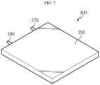
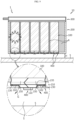
- FIGS. 7 and 8 are diagrams illustrating the pack cover of the battery pack of FIG. 2 .
- the pack cover 300 may be coupled to the pack case 200, and may cover the at least one battery cell 100 on a side opposite to the vent portion 150. Specifically, the pack cover 300 may cover the opposite end 106 of the at least one battery cell 100. More specifically, the pack cover 300 may be coupled to the upper end of the pack case 200 and may cover the upper end 106 of the plurality of battery cells 200.
- the pack cover 300 may include a cooling channel 310, a bottom heat sink 330, a top heat sink 350, a cooling water inlet port 370 and a cooling water outlet port 390.
- the cooling channel 310 may be provided inside the pack cover 300 to cool the at least one battery cell 100, and in this embodiment, the plurality of battery cells 100.
- a cooling water for cooling the battery cells 100 may circulate in the cooling channel 310.
- the bottom heat sink 330 may be positioned in contact with the at least one battery cell 100.
- the bottom heat sink 330 may be positioned in contact with the opposite end 106 of the plurality of battery cells 100. Specifically, the bottom heat sink 330 may come into surface contact with the upper end 106 of the plurality of battery cells 100.
- the at least one battery cell 100 may be fixed to the lower surface of the bottom heat sink 330.
- the opposite end 106 of the plurality of battery cells 100 may be fixed to the lower surface of the bottom heat sink 330.
- the upper end 106 of the plurality of battery cells 100 may be fixed to the lower surface of the bottom heat sink 330 through the thermally conductive adhesive.
- the bottom heat sink 330 is fixed in surface contact with the upper end 106 of the battery cells 100, it is possible to improve the cooling performance of the battery cells 100 and guide the more stable mounting of the battery cells 100 in the pack case 200.
- the top heat sink 350 may be coupled to the bottom heat sink 330 to form the cooling channel 310 inside.
- the top heat sink 350 may be coupled to the case body 210 of the pack case 200.
- the cooling water inlet port 370 is used to guide the cooling water to the cooling channel 310, and may protrude from one side of the top heat sink 350, and may be connected in communication with the cooling unit.
- the cooling water inlet port 370 may protrude at a side of the side surface of the top heat sink 350. Accordingly, in this embodiment, it is possible to form a flat structure in the heightwise direction of the battery pack 10, thereby achieving a more compact structure of the battery pack 10.
- the cooling water outlet port 390 is used to deliver the cooling water in the cooling channel 310 to the cooling unit, and may communicate with the cooling channel 310 and may be provided in the top heat sink 350, spaced apart from the cooling water inlet port 370.
- the cooling water outlet port 390 may protrude from a side of the side surface of the top heat sink 350, spaced a predetermined distance apart from the cooling water inlet port 370. Accordingly, in this embodiment, it is possible to form a flat structure in the heightwise direction of the battery pack 10, thereby achieving a more compact structure of the battery pack 10.
- a heat sink structure for cooling the battery cells 100 is integrally formed in the top cover 300, it is possible to reduce the total size of the battery pack 10 and significantly increase the energy density of the battery pack 10, compared to the conventional heat sink structure provided separately from the top cover 300.
- the busbar unit 400 is used for electrical connection of the plurality of battery cells 100, and may be provided below the pack case 200.
- the electrical connection may be a parallel and/or series connection.
- the busbar unit 400 may be electrically connected to the positive electrode 110 and the negative electrode 130 of the plurality of battery cells 100, and may be electrically connected to an external charge/discharge line through a connector.
- both the positive electrode 110 and the negative electrode 130 of the plurality of battery cells 100 are provided on a side of the battery cells 100, to be specific, the lower side of the battery cells 100, it may be easier to make an electrical connection to the busbar unit 400.
- FIG. 9 is a diagram illustrating the gas release of the battery cell through the safety space when an overheat or fire situation occurs in the battery pack mounted in the vehicle of FIG. 1 .
- gas G or flame may occur when at least one of the battery cells 100 of the battery pack 10 is overheated or catches fire due to an abnormal situation in the battery pack 10 of the vehicle 1.
- the vent portion 150 of the battery cells 100 is positioned toward the lower side of the battery pack 10, the gas G released from the battery cells 100 through the vent portion 150 may be forced out downward from the pack case 200.
- the gas G generated from the battery cells 100 due to an abnormal situation may be guided to pass through the vent portion 150 positioned toward the lower side of the pack case 200 and move to the safety space S below the pack case 200 through the opening 235 of the cell insertion portion 230 of the pack case 200.
- the gas G or flame is guided downward below the battery pack 10 at which the driver and passengers are located, not upward above the battery pack 10, thereby ensuring safety of the driver and passengers.
- the battery pack 10 has the safety space S on the under body frame 5 of the vehicle 1 to guide the release of the gas G and mitigate external impacts, thereby ensuring safety of the driver and passengers of the vehicle 1 when the above-described dangerous situation occurs. Accordingly, in this embodiment, it is possible to provide the battery pack 10 having higher safety performance when the battery pack 10 is mounted in the vehicle 1.
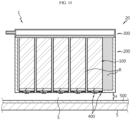
- FIG. 10 is a diagram illustrating a battery pack according to another embodiment of the present disclosure.
- the battery pack 20 according to this embodiment is similar to the battery pack 10 of the previous embodiment, an overlapping description of substantially identical or similar elements to the previous embodiment is omitted, and hereinafter, difference(s) between this embodiment and the previous embodiment will be described.
- the vehicle 1 may include the battery pack 20.
- the battery pack 20 may include the battery cells 100, the pack case 200, the pack cover 300, the busbar unit 400 and a reinforcing plate 500.
- the battery cells 100, the pack case 200, the pack cover 300 and the busbar unit 400 are substantially identical or similar to the previous embodiment, and hereinafter, an overlapping description is omitted.
- the reinforcing plate 500 may be mounted in the under body frame 5 of the vehicle 1.
- the lower surface of the pack case 200 may be spaced the predetermined height H apart from the reinforcing plate 500 to form the safety space S.
- the reinforcing plate 500 may mitigate the flame, thereby minimizing or delaying damage to the under body frame 5 to the maximum.
- the battery pack 10, 20 with a more compact structure and increased energy density and the vehicle 1 including the battery pack 10, 20.
- the battery pack 10, 20 with improved safety performance and the vehicle 1 including the battery pack 10, 20.
Landscapes
- Chemical & Material Sciences (AREA)
- Engineering & Computer Science (AREA)
- Chemical Kinetics & Catalysis (AREA)
- Electrochemistry (AREA)
- General Chemical & Material Sciences (AREA)
- Manufacturing & Machinery (AREA)
- Transportation (AREA)
- Mechanical Engineering (AREA)
- Aviation & Aerospace Engineering (AREA)
- Life Sciences & Earth Sciences (AREA)
- Power Engineering (AREA)
- Sustainable Energy (AREA)
- Sustainable Development (AREA)
- Combustion & Propulsion (AREA)
- Battery Mounting, Suspending (AREA)
- Secondary Cells (AREA)
- Gas Exhaust Devices For Batteries (AREA)
Abstract
Description
- The present disclosure relates to a battery pack and a vehicle comprising the same.
- The present application claims the benefit of
Korean Patent Application No. 10-2021-0003547 filed on January 11, 2021 - Due to their characteristics of being easily applicable to various products and electrical properties such as a high energy density, secondary batteries are not only commonly applied to portable devices, but universally applied to electric vehicles (EVs) or hybrid electric vehicle (HEVs) that are driven by an electrical driving source. Such secondary batteries are gaining attention for their primary advantage of remarkably reducing the use of fossil fuels and not generating by-products from the use of energy, making it a new eco-friendly and energy efficient source of energy.
- The types of secondary batteries widely used at present include lithium ion batteries, lithium polymer batteries, nickel cadmium batteries, nickel hydrogen batteries, nickel zinc batteries or the like. This unit secondary battery cell, i.e., a unit battery cell has an operating voltage of about 2.5V to 4.5V. Accordingly, when a higher output voltage is required, a plurality of battery cells may be connected in series to fabricate a battery pack. Additionally, the battery pack may be fabricated by connecting the plurality of battery cells in parallel according to the charge/discharge capacity required for the battery pack. Accordingly, the number of battery cells included in the battery pack may be variously set depending on the required output voltage or charge/discharge capacity.
- Meanwhile, when fabricating the battery pack by connecting the plurality of battery cells in series/in parallel, it is general to make a battery module including at least one battery cell, and then fabricate a battery pack or a battery rack using at least one battery module with an addition of any other component.
- In general, the conventional battery pack case includes a plurality of battery cells, a pack case to accommodate the plurality of battery cells, a pack cover to cover the plurality of battery cells at the upper part of the pack case and a heat sink mounted below the pack case to cool the plurality of battery cells. Here, the conventional pack case includes an assembly of a plurality of plate members to accommodate the plurality of battery cells.
- However, in the case of the conventional battery pack, the plurality of plate members that constitute the pack case increases the total size of the battery pack, and thus there is an energy density disadvantage. Additionally, in the case of the conventional battery pack, additional members such as the top cover and the heat sink reduce the total energy density.
- Furthermore, when an overheat or fire situation occurs in the conventional battery pack, gas emitting from the battery cells moves to the upper part of the battery pack, which poses a great threat to safety of a driver and passengers located on the battery pack.
- Accordingly, it is aimed at providing a battery pack with a more compact structure and increased energy density as well as improved safety performance and a vehicle including the battery pack.
- Accordingly, the present disclosure is directed to providing a battery pack with a more compact structure and increased energy density and a vehicle comprising the same.
- Additionally, the present disclosure is further directed to providing a battery pack with improved safety performance and a vehicle comprising the same.
- To solve the above-described problem, the present disclosure provides a battery pack including at least one battery cell including a vent portion to force gas out; and a pack case which accommodates the at least one battery cell such that the vent portion faces a lower side of the battery pack, with the vent portion exposed from the battery pack.
- The battery pack may include a pack cover which is coupled to the pack case and covers the at least one battery cell on a side opposite to the vent portion.
- The pack cover may have a cooling channel inside to cool the at least one battery cell.
- The pack cover may include a bottom heat sink positioned in contact with the at least one battery cell; and a top heat sink coupled to the bottom heat sink to form the cooling channel inside.
- The at least one battery cell may be fixed to a lower surface of the bottom heat sink.
- The pack cover may include a cooling water inlet port which communicates with the cooling channel, and protrudes from a side of the top heat sink; and a cooling water outlet port which is provided in the top heat sink, spaced apart from the cooling water inlet port, and communicates with the cooling channel.
- The pack case may include a case body which covers the at least one battery cell, and is coupled to the pack cover; and a cell insertion portion provided on a bottom of the case body, into which the at least one battery cell is inserted.
- The cell insertion portion may have at least one opening through which the vent portion is exposed from the pack case.
- The cell insertion portion may protrude to a predetermined height from a lower side of the pack case.
- The cell insertion portion may protrude downward below the pack case more than the vent portion.
- The cell insertion portion may cover a side of a bottom of the at least one battery cell.
- An inner space of the pack case may be filled with a resin material to cover the at least one battery cell.
- A plurality of battery cells may be provided, and the resin material may be filled between the plurality of battery cells.
- The resin material may include a potting resin.
- The vent portion may be provided at an end of a lengthwise direction of the at least one battery cell, and the end of the at least one battery cell may be positioned below the pack case.
- The pack cover may cover an opposite end of the at least one battery cell.
- Additionally, the present disclosure provides a vehicle including at least one battery pack according to the above-described embodiments.
- A lower surface of the pack case may be spaced a predetermined height apart from an under body frame of the vehicle to form a safety space.
- The battery pack may include a reinforcing plate mounted in an under body frame of the vehicle.
- A lower surface of the pack case may be spaced a predetermined height apart from the reinforcing plate to form a safety space.
- According to the various embodiments as described above, it is possible to provide a battery pack with a more compact structure and increased energy density and a vehicle comprising the same.
- Additionally, according to the various embodiments as described above, it is possible to provide a battery pack with improved safety performance and a vehicle comprising the same.
- The accompanying drawings illustrate a preferred embodiment of the present disclosure, and together with the detailed description of the present disclosure described below, serve to provide a further understanding of the technical aspects of the present disclosure, and thus the present disclosure should not be construed as being limited to the drawings.
-
FIG. 1 is a diagram illustrating a battery pack mounted in a vehicle according to an embodiment of the present disclosure. -
FIG. 2 is an exploded perspective view of the battery pack ofFIG. 1 . -
FIG. 3 is a diagram illustrating battery cells of the battery pack ofFIG. 2 . -
FIG. 4 is a diagram illustrating a pack case of the battery pack ofFIG. 2 . -
FIGS. 5 and6 are diagrams illustrating a pack case according to another embodiment of the battery pack ofFIG. 2 . -
FIGS. 7 and8 are diagrams illustrating a pack cover of the battery pack ofFIG. 2 . -
FIG. 9 is a diagram illustrating the gas release of a battery cell through a safety space when an overheat or fire situation occurs in a battery pack mounted in the vehicle ofFIG. 1 . -
FIG. 10 is a diagram illustrating a battery pack according to another embodiment of the present disclosure. - The present disclosure will become apparent by describing a preferred embodiment of the present disclosure in detail with reference to the accompanying drawings. The embodiment described herein is provided by way of illustration to help an understanding of the present disclosure, and it should be understood that various modifications may be made to the present disclosure in other embodiments than the embodiment described herein. Additionally, to help an understanding of the present disclosure, the accompanying drawings are not shown in true scale and may depict some exaggerated elements.
-
FIG. 1 is a diagram illustrating a battery pack mounted in a vehicle according to an embodiment of the present disclosure. - Referring to
FIG. 1 , thevehicle 1 may be an electric vehicle or a hybrid electric vehicle, and may include at least onebattery pack 10. In thevehicle 1, a seating space having an interior sheet for a driver and passengers may be provided above the at least onebattery pack 10, and an underbody frame 5 of thevehicle 1 may be provided below thebattery pack 10. - The
battery pack 10 may be spaced a predetermined height H apart from the underbody frame 5 provided at the lower part of thevehicle 1. Thebattery pack 10 is spaced the predetermined height H apart to form a safety space S, and hereinafter, the related placement structure of thebattery pack 10 and its entire configuration will be described in more detail with reference to the related drawings. -
FIG. 2 is an exploded perspective view of the battery pack ofFIG. 1 . - Referring to
FIG. 2 , thebattery pack 10 may include abattery cell 100 and apack case 200. Meanwhile, thebattery pack 10 may further include apack cover 300, abusbar unit 400 and various types of electrical components that constitute thebattery pack 10. - The
battery cell 100 may be a secondary battery, for example, a cylindrical secondary battery, a pouch-type secondary battery or a prismatic secondary battery. Hereinafter, this embodiment is described based on a cylindrical secondary battery as thebattery cell 100. - At least one
battery cell 100 may be provided. Hereinafter, this embodiment is described based on a plurality ofbattery cells 100. - Hereinafter, the plurality of
battery cells 100 will be described in more detail. -
FIG. 3 is a diagram illustrating the battery cells of the battery pack ofFIG. 2 . - Referring to
FIG. 3 , a resin material R may be filled between the plurality ofbattery cells 100. The resin material R may fix the plurality ofbattery cells 100 more stably and transfer heat generated from the plurality ofbattery cells 100 more uniformly, thereby increasing the cooling performance of the plurality ofbattery cells 100. - The resin material R may include a potting resin. The potting resin may be formed by injecting a thin resin material into the plurality of
battery cells 100 and curing it. Here, the injection of the resin material R may be performed at room temperature of about 15°C to 25°C to prevent thermal damage of the plurality ofbattery cells 100. - Specifically, the resin material R may include a silicone resin. The resin material R is not limited thereto, and may include any resin material other than the silicone resin, capable of fixing the
battery cells 100 and improving the heat transfer efficiency. - A
positive electrode 110 and anegative electrode 130 for electrical connection of thebattery cells 100 may be provided at alower end 102 of the plurality ofbattery cells 100. Here, thepositive electrode 110 may be provided at the center of thelower end 102 of thebattery cell 100, and thenegative electrode 130 may be provided at the edge of thelower end 102 of thebattery cell 100. In thebattery cell 100, thepositive electrode 110 and thenegative electrode 130 are not limited thereto and may be provided with any other placement structure such that they are insulated from each other. - The
positive electrode 110 and thenegative electrode 130 of the plurality ofbattery cells 100 may be electrically connected to thebusbar unit 400 as described below on the lower side of the pack case 200 (seeFIGS. 1 and2 ). - A
vent portion 150 may be provided at thelower end 102 of each of the plurality ofbattery cells 100 to force gas G (seeFIG. 7 ) generated from eachbattery cell 100 out. - The
vent portion 150 may be provided at theend 102 of the lengthwise direction of thebattery cell 100. Theend 102 of thebattery cell 100 may be positioned below the pack case 200 (seeFIGS. 1 and2 ). - Specifically, the
vent portion 150 may be provided at thelower end 102 of thebattery cell 100, and may be positioned at the lower part of thepack case 200. More specifically, thevent portion 150 may be provided in a positive electrode plate area near the center of the lower end of thebattery cell 100 having thepositive electrode 110. - The
vent portion 150 may be formed with a smaller thickness than any other area at thelower end 102 of thebattery cell 100. Thevent portion 150 ruptures to force the gas G (seeFIG. 7 ) out of thebattery cell 100 more easily when the internal pressure increases above a predetermined level due to an abnormal situation in thebattery cell 100. - The
vent portion 150 may be provided in the shape of an opening or notch of a predetermined size. Furthermore, thevent portion 150 may have a structure in which a film that ruptures above the predetermined level of pressure is added to the opening of the predetermined size. - In this embodiment, as the
vent portion 150 is positioned at the lower part of thepack case 200, when an overheat or fire occurs due to an abnormal situation in thebattery cell 100, gas or flame may move out through the lower side of thepack case 200, not the upper side of thepack case 200. Accordingly, when the abnormal situation occurs, it is possible to ensure safety of the driver and passengers of thevehicle 1 positioned above thepack case 200 to the maximum, thereby minimizing damage to the passengers. - The
vent portion 150 may be provided near the center of thelower end 102 of thebattery cell 100. Thevent portion 150 is not limited thereto, and may be provided at any other location for forcing gas toward the lower part of thebattery cell 100. - The
upper end 106 of the plurality ofbattery cells 100 may be provided in a flat shape, and may be fixed to the lower surface of the pack cover 300 (seeFIGS. 1 and2 ). In this embodiment, since thepositive electrode 110 and thenegative electrode 130 are provided at thelower end 102 of the plurality ofbattery cells 100, as the upper end of the plurality ofbattery cells 100 is provided in a flat shape having no uneven structure, the upper end of all the plurality ofbattery cells 100 may be mounted in contact with the lower surface of thepack cover 300 without a predetermined gap space on the lower surface of thepack cover 300. - Here, the adhesive mounting of the plurality of
battery cells 100 and thepack cover 300 may be accomplished through a thermally conductive adhesive. Meanwhile, thepack cover 300 may be provided as a heat sink to cool thebattery cells 100 as described below. - In this embodiment, as the upper end of all the
battery cells 100 is mounted in contact with the lower surface of thepack cover 300 without an uneven structure, it is possible to significantly increase the cooling performance of thebattery cells 100. - Furthermore, in this embodiment, through the contact placement structure between the
upper end 106 of thebattery cells 100 and thepack cover 300, it is possible to reduce the total height of the vertical direction of thebattery pack 10, thereby achieving a more compact structure of thebattery pack 10 and significantly increasing the total energy density. Accordingly, in this embodiment, it is possible to mount the maximum number of battery packs 10 in thevehicle 1, thereby significantly increasing the total battery capacity of thevehicle 1. - Meanwhile, any other member such as a thermally conductive sheet may be interposed between the
upper end 106 of thebattery cells 100 and thepack cover 300 to increase the cooling performance. Furthermore, any other member such as a thermally conductive space having a groove structure for fixing thebattery cells 100 more stably may be provided at theupper end 106 of thebattery cells 100. -
FIG. 4 is a diagram illustrating the pack case of the battery pack ofFIG. 2 . - Referring to
FIG. 4 together withFIGS. 1 and2 , thepack case 200 may accommodate the at least onebattery cell 100. Specifically, thepack case 200 may accommodate thebattery cells 100 such that thevent portion 150 of thebattery cells 100 face the lower part of thebattery pack 10, and may expose thevent portion 150 from thebattery pack 10. - Furthermore, the lower surface of the
pack case 200 may be spaced the predetermined height H apart from the underbody frame 5 of thevehicle 1 to form the safety space S. - When an external impact occurs in the under
body frame 5 of thevehicle 1, the safety space S may prevent the direct transfer of the external impact to thebattery pack 10, thereby effectively preventing damage to thebattery pack 10 caused by the external impact and further, explosion of thebattery pack 10. - Furthermore, when an overheat or fire situation occurs due to an abnormal situation in the
battery pack 10, the safety space S may guide gas or flame emitting from thebattery cells 100 to move to the lower part of thevehicle 1, not the driver and passengers. - The inner space of the
pack case 200 may be filled with the resin material R to cover the at least onebattery cell 100, and in this embodiment, the plurality ofbattery cells 100. Specifically, the resin material R may be filled in thepack case 200 such that thebattery cells 100 are submerged in at least part, so the resin material R may cover the plurality ofbattery cells 100. - The
pack case 200 may include acase body 210 and acell insertion portion 230. - The
case body 210 may be coupled to thepack cover 300 as described below, to cover the at least onebattery cell 100, and in this embodiment, the plurality ofbattery cells 100. The resin material R may be filled in thecase body 210. - The
cell insertion portion 230 may be provided on the bottom of thecase body 210, and theend 102 of the at least onebattery cell 100, and in this embodiment, the plurality ofbattery cells 100 may be inserted into thecell insertion portion 230. Specifically, a plurality ofcell insertion portions 230 may be provided, and thelower end 102 of the plurality ofbattery cells 100 may be inserted into the plurality ofcell insertion portions 230. - Each of the plurality of
cell insertion portions 230 may have at least oneopening 235 to accommodate thepositive electrode 110 of thebattery cells 100 and expose thevent portion 150 of thebattery cells 100 from thepack case 200. - The at least one
opening 235 may be sealed up with a thin film that may rupture by gas coming out of thevent portion 150. This is to prevent water filtration through the at least oneopening 235. -
FIGS. 5 and6 are diagrams illustrating a pack case according to another embodiment of the battery pack ofFIG. 2 . - Referring to
FIGS. 5 and6 , acell insertion portion 240 may be provided on the bottom of thecase body 210. Thecell insertion portion 240 may protrude to a predetermined height from the lower side of thepack case 200. Here, thecell insertion portion 240 may protrude downward from thepack case 200 more than thevent portion 150. Thecell insertion portion 240 may form a protruding rib structure on the bottom of thepack case 200. - In this embodiment, it is possible to prevent the interference with the
vent portion 150 of thebattery cells 100 more effectively through thecell insertion portion 240 of the protruding rib structure, thereby forcing gas out more quickly without interference of thecell insertion portion 240 when forcing gas out through thevent portion 150 when thebattery cells 100 are overheated. - Additionally, the
cell insertion portion 240 may cover one side of the bottom of the at least onebattery cell 100, and in this embodiment, the plurality ofbattery cells 100. Accordingly, thecell insertion portion 240 may fix at least onebattery cell 100, and in this embodiment, the plurality ofbattery cells 100 more firmly. - Additionally, in the same way as the
opening 235 of the previous embodiment, thecell insertion portion 240 may have anopening 245. Furthermore, thecell insertion portion 240 may have at least onefastening hole 247 through which a fastening member for coupling to thepack cover 300 passes or is fastened. -
FIGS. 7 and8 are diagrams illustrating the pack cover of the battery pack ofFIG. 2 . - Referring to
FIGS. 7 and8 together withFIGS. 1 and2 , thepack cover 300 may be coupled to thepack case 200, and may cover the at least onebattery cell 100 on a side opposite to thevent portion 150. Specifically, thepack cover 300 may cover theopposite end 106 of the at least onebattery cell 100. More specifically, thepack cover 300 may be coupled to the upper end of thepack case 200 and may cover theupper end 106 of the plurality ofbattery cells 200. - The
pack cover 300 may include acooling channel 310, abottom heat sink 330, atop heat sink 350, a coolingwater inlet port 370 and a coolingwater outlet port 390. - The cooling
channel 310 may be provided inside thepack cover 300 to cool the at least onebattery cell 100, and in this embodiment, the plurality ofbattery cells 100. A cooling water for cooling thebattery cells 100 may circulate in thecooling channel 310. - The
bottom heat sink 330 may be positioned in contact with the at least onebattery cell 100. In this embodiment, thebottom heat sink 330 may be positioned in contact with theopposite end 106 of the plurality ofbattery cells 100. Specifically, thebottom heat sink 330 may come into surface contact with theupper end 106 of the plurality ofbattery cells 100. - Furthermore, the at least one
battery cell 100 may be fixed to the lower surface of thebottom heat sink 330. In this embodiment, theopposite end 106 of the plurality ofbattery cells 100 may be fixed to the lower surface of thebottom heat sink 330. Specifically, theupper end 106 of the plurality ofbattery cells 100 may be fixed to the lower surface of thebottom heat sink 330 through the thermally conductive adhesive. - As described above, in this embodiment, as the
bottom heat sink 330 is fixed in surface contact with theupper end 106 of thebattery cells 100, it is possible to improve the cooling performance of thebattery cells 100 and guide the more stable mounting of thebattery cells 100 in thepack case 200. - The
top heat sink 350 may be coupled to thebottom heat sink 330 to form thecooling channel 310 inside. Thetop heat sink 350 may be coupled to thecase body 210 of thepack case 200. - The cooling
water inlet port 370 is used to guide the cooling water to thecooling channel 310, and may protrude from one side of thetop heat sink 350, and may be connected in communication with the cooling unit. - Specifically, the cooling
water inlet port 370 may protrude at a side of the side surface of thetop heat sink 350. Accordingly, in this embodiment, it is possible to form a flat structure in the heightwise direction of thebattery pack 10, thereby achieving a more compact structure of thebattery pack 10. - The cooling
water outlet port 390 is used to deliver the cooling water in thecooling channel 310 to the cooling unit, and may communicate with the coolingchannel 310 and may be provided in thetop heat sink 350, spaced apart from the coolingwater inlet port 370. - Specifically, the cooling
water outlet port 390 may protrude from a side of the side surface of thetop heat sink 350, spaced a predetermined distance apart from the coolingwater inlet port 370. Accordingly, in this embodiment, it is possible to form a flat structure in the heightwise direction of thebattery pack 10, thereby achieving a more compact structure of thebattery pack 10. - As described above, in this embodiment, as a heat sink structure for cooling the
battery cells 100 is integrally formed in thetop cover 300, it is possible to reduce the total size of thebattery pack 10 and significantly increase the energy density of thebattery pack 10, compared to the conventional heat sink structure provided separately from thetop cover 300. - Additionally, in this embodiment, it is possible to increase the assembly process efficiency of the
battery pack 10 and reduce the fabrication cost of thebattery pack 10 through the integratedtop cover 300 structure, thereby increasing the price competitiveness of thebattery pack 10. - Referring back to
FIG. 2 , thebusbar unit 400 is used for electrical connection of the plurality ofbattery cells 100, and may be provided below thepack case 200. The electrical connection may be a parallel and/or series connection. Thebusbar unit 400 may be electrically connected to thepositive electrode 110 and thenegative electrode 130 of the plurality ofbattery cells 100, and may be electrically connected to an external charge/discharge line through a connector. - In this embodiment, as both the
positive electrode 110 and thenegative electrode 130 of the plurality ofbattery cells 100 are provided on a side of thebattery cells 100, to be specific, the lower side of thebattery cells 100, it may be easier to make an electrical connection to thebusbar unit 400. - That is, in this embodiment, with the structure in which the
positive electrode 110 and thenegative electrode 130 of the plurality ofbattery cells 100 are positioned in the same direction, it is possible to simplify the connection structure to thebusbar unit 400 and reduce the occupied volume, compared to a structure which the positive electrode and the negative electrode are positioned in the opposite directions. - Accordingly, in this embodiment, it is possible to simplify the electrical connection structure of the
busbar unit 400 and thebattery cells 100, make the entire structure compact and improve the energy density. - Hereinafter, when an overheat or fire situation occurs in the
battery pack 10 according to this embodiment, the mechanism to force gas out or ensure safety of the battery cell through the safety space S will be described in more detail. -
FIG. 9 is a diagram illustrating the gas release of the battery cell through the safety space when an overheat or fire situation occurs in the battery pack mounted in the vehicle ofFIG. 1 . - Referring to
FIG. 9 , gas G or flame may occur when at least one of thebattery cells 100 of thebattery pack 10 is overheated or catches fire due to an abnormal situation in thebattery pack 10 of thevehicle 1. - In this embodiment, as the
vent portion 150 of thebattery cells 100 is positioned toward the lower side of thebattery pack 10, the gas G released from thebattery cells 100 through thevent portion 150 may be forced out downward from thepack case 200. - Specifically, the gas G generated from the
battery cells 100 due to an abnormal situation may be guided to pass through thevent portion 150 positioned toward the lower side of thepack case 200 and move to the safety space S below thepack case 200 through theopening 235 of thecell insertion portion 230 of thepack case 200. - That is, in this embodiment, in case of a dangerous situation such as the overheat or fire situation, the gas G or flame is guided downward below the
battery pack 10 at which the driver and passengers are located, not upward above thebattery pack 10, thereby ensuring safety of the driver and passengers. - As described above, in this embodiment, the
battery pack 10 has the safety space S on the underbody frame 5 of thevehicle 1 to guide the release of the gas G and mitigate external impacts, thereby ensuring safety of the driver and passengers of thevehicle 1 when the above-described dangerous situation occurs. Accordingly, in this embodiment, it is possible to provide thebattery pack 10 having higher safety performance when thebattery pack 10 is mounted in thevehicle 1. -
FIG. 10 is a diagram illustrating a battery pack according to another embodiment of the present disclosure. - As the
battery pack 20 according to this embodiment is similar to thebattery pack 10 of the previous embodiment, an overlapping description of substantially identical or similar elements to the previous embodiment is omitted, and hereinafter, difference(s) between this embodiment and the previous embodiment will be described. - Referring to
FIG. 10 , thevehicle 1 may include thebattery pack 20. - The
battery pack 20 may include thebattery cells 100, thepack case 200, thepack cover 300, thebusbar unit 400 and a reinforcingplate 500. - The
battery cells 100, thepack case 200, thepack cover 300 and thebusbar unit 400 are substantially identical or similar to the previous embodiment, and hereinafter, an overlapping description is omitted. - The reinforcing
plate 500 may be mounted in the underbody frame 5 of thevehicle 1. The lower surface of thepack case 200 may be spaced the predetermined height H apart from the reinforcingplate 500 to form the safety space S. - In this embodiment, it is possible to increase the structure strength of the
vehicle 1 through the reinforcingplate 500. Furthermore, in this embodiment, when an external impact occurs outside the underbody frame 5 of thevehicle 1, it is possible to absorb and mitigate the external impact through the reinforcingplate 500 together with the underbody frame 5, thereby minimizing the risk of impact transfer to thepack case 200 of thebattery pack 10. - Additionally, in this embodiment, when flame caused by an abnormal situation in the
battery cell 100 goes out below thepack case 200, the reinforcingplate 500 may mitigate the flame, thereby minimizing or delaying damage to the underbody frame 5 to the maximum. - According to the various embodiments as described above, it is possible to provide the
battery pack vehicle 1 including thebattery pack - Additionally, according to the various embodiments as described above, it is possible to provide the
battery pack vehicle 1 including thebattery pack - While the preferred embodiment of the present disclosure has been hereinabove shown and described, the present disclosure is not limited to the above-described particular embodiment, and it is obvious to those skilled in the art that a variety of modifications may be made thereto without departing from the essence of the present disclosure claimed in the appended claims, and such modifications should not be individually understood from the technical aspect or scope of the present disclosure.
Claims (20)
- A battery pack, comprising:at least one battery cell including a vent portion to force gas out; anda pack case which accommodates the at least one battery cell such that the vent portion faces a lower side of the battery pack, with the vent portion exposed from the battery pack.
- The battery pack according to claim 1, comprising:
a pack cover which is coupled to the pack case and covers the at least one battery cell on a side opposite to the vent portion. - The battery pack according to claim 2, wherein the pack cover has a cooling channel inside to cool the at least one battery cell.
- The battery pack according to claim 3, wherein the pack cover includes:a bottom heat sink positioned in contact with the at least one battery cell; anda top heat sink coupled to the bottom heat sink to form the cooling channel inside.
- The battery pack according to claim 4, wherein the at least one battery cell is fixed to a lower surface of the bottom heat sink.
- The battery pack according to claim 5, wherein the pack cover includes:a cooling water inlet port which communicates with the cooling channel, and protrudes from a side of the top heat sink; anda cooling water outlet port which is provided in the top heat sink, spaced apart from the cooling water inlet port, and communicates with the cooling channel.
- The battery pack according to claim 2, wherein the pack case includes:a case body which covers the at least one battery cell, and is coupled to the pack cover; anda cell insertion portion provided on a bottom of the case body, into which the at least one battery cell is inserted.
- The battery pack according to claim 7, wherein the cell insertion portion has at least one opening through which the vent portion is exposed from the pack case.
- The battery pack according to claim 7, wherein the cell insertion portion protrudes to a predetermined height from a lower side of the pack case.
- The battery pack according to claim 9, wherein the cell insertion portion protrudes downward below the pack case more than the vent portion.
- The battery pack according to claim 9, wherein the cell insertion portion covers a side of a bottom of the at least one battery cell.
- The battery pack according to claim 1, wherein an inner space of the pack case is filled with a resin material to cover the at least one battery cell.
- The battery pack according to claim 12, wherein a plurality of battery cells is provided, and
the resin material is filled between the plurality of battery cells. - The battery pack according to claim 13, wherein the resin material includes a potting resin.
- The battery pack according to claim 2, wherein the vent portion is provided at an end of a lengthwise direction of the at least one battery cell, and
the end of the at least one battery cell is positioned below the pack case. - The battery pack according to claim 15, wherein the pack cover covers an opposite end of the at least one battery cell.
- A vehicle comprising at least one battery pack according to claim 1.
- The vehicle according to claim 17, wherein a lower surface of the pack case is spaced a predetermined height apart from an under body frame of the vehicle to form a safety space.
- The vehicle according to claim 17, wherein the battery pack includes a reinforcing plate mounted in an under body frame of the vehicle.
- The vehicle according to claim 19, wherein a lower surface of the pack case is spaced a predetermined height apart from the reinforcing plate to form a safety space.
Priority Applications (1)
| Application Number | Priority Date | Filing Date | Title |
|---|---|---|---|
| EP25192378.5A EP4664644A1 (en) | 2021-01-11 | 2022-01-11 | Battery pack and vehicle including same |
Applications Claiming Priority (2)
| Application Number | Priority Date | Filing Date | Title |
|---|---|---|---|
| KR20210003547 | 2021-01-11 | ||
| PCT/KR2022/000502 WO2022149965A1 (en) | 2021-01-11 | 2022-01-11 | Battery pack and vehicle including same |
Related Child Applications (2)
| Application Number | Title | Priority Date | Filing Date |
|---|---|---|---|
| EP25192378.5A Division-Into EP4664644A1 (en) | 2021-01-11 | 2022-01-11 | Battery pack and vehicle including same |
| EP25192378.5A Division EP4664644A1 (en) | 2021-01-11 | 2022-01-11 | Battery pack and vehicle including same |
Publications (3)
| Publication Number | Publication Date |
|---|---|
| EP4181298A1 true EP4181298A1 (en) | 2023-05-17 |
| EP4181298A4 EP4181298A4 (en) | 2024-06-05 |
| EP4181298B1 EP4181298B1 (en) | 2025-09-24 |
Family
ID=82357337
Family Applications (2)
| Application Number | Title | Priority Date | Filing Date |
|---|---|---|---|
| EP25192378.5A Pending EP4664644A1 (en) | 2021-01-11 | 2022-01-11 | Battery pack and vehicle including same |
| EP22736942.8A Active EP4181298B1 (en) | 2021-01-11 | 2022-01-11 | Battery pack and vehicle including same |
Family Applications Before (1)
| Application Number | Title | Priority Date | Filing Date |
|---|---|---|---|
| EP25192378.5A Pending EP4664644A1 (en) | 2021-01-11 | 2022-01-11 | Battery pack and vehicle including same |
Country Status (8)
| Country | Link |
|---|---|
| US (5) | US12562426B2 (en) |
| EP (2) | EP4664644A1 (en) |
| JP (1) | JP7536897B2 (en) |
| KR (3) | KR102752032B1 (en) |
| CN (1) | CN115803951B (en) |
| ES (1) | ES3057109T3 (en) |
| PL (1) | PL4181298T3 (en) |
| WO (1) | WO2022149965A1 (en) |
Cited By (3)
| Publication number | Priority date | Publication date | Assignee | Title |
|---|---|---|---|---|
| EP4391174A1 (en) * | 2022-12-19 | 2024-06-26 | Rimac Technology LLC | Mounted battery system |
| EP4645526A1 (en) * | 2024-04-30 | 2025-11-05 | Eve Energy Co., Ltd. | Battery pack |
| EP4578065A4 (en) * | 2023-07-26 | 2026-01-07 | Lg Energy Solution Ltd | Battery pack |
Families Citing this family (12)
| Publication number | Priority date | Publication date | Assignee | Title |
|---|---|---|---|---|
| DE102021109302B3 (en) * | 2021-04-14 | 2022-07-28 | Dr. Ing. H.C. F. Porsche Aktiengesellschaft | battery device |
| EP4395040A4 (en) * | 2022-08-31 | 2025-04-30 | LG Energy Solution, Ltd. | BATTERY PACK AND VEHICLE WITH IT |
| EP4611127A4 (en) * | 2022-12-02 | 2025-12-31 | Lg Energy Solution Ltd | BATTERY PACK AND METHOD FOR MANUFACTURING IT |
| CN119111013A (en) * | 2022-12-22 | 2024-12-10 | 株式会社Lg新能源 | Battery module, battery pack and vehicle including the battery module |
| KR102728167B1 (en) * | 2022-12-22 | 2024-11-08 | 주식회사 엘지에너지솔루션 | Battery module, battery pack and vehicle including the same |
| CN220065796U (en) * | 2023-05-08 | 2023-11-21 | 远景动力技术(江苏)有限公司 | Battery module and battery pack |
| CN221596667U (en) * | 2024-01-17 | 2024-08-23 | 株式会社Aesc日本 | A battery module and a battery pack |
| WO2025165008A1 (en) * | 2024-01-31 | 2025-08-07 | 주식회사 엘지에너지솔루션 | Battery pack |
| KR20250147389A (en) * | 2024-04-04 | 2025-10-13 | 주식회사 엘지에너지솔루션 | Battery pack with improved cooling performance |
| EP4683047A1 (en) * | 2024-05-29 | 2026-01-21 | LG Energy Solution Ltd. | Battery pack and vehicle comprising same |
| US20260005331A1 (en) * | 2024-06-27 | 2026-01-01 | Kyma Batteries LLC | Battery cells with thermally conductive potting |
| DE102024128968A1 (en) * | 2024-10-08 | 2026-04-09 | Bayerische Motoren Werke Aktiengesellschaft | High-voltage storage and methods for manufacturing a high-voltage storage system |
Family Cites Families (40)
| Publication number | Priority date | Publication date | Assignee | Title |
|---|---|---|---|---|
| JPS56155719A (en) | 1980-05-07 | 1981-12-02 | Mitsubishi Chem Ind Ltd | Solvent welding device |
| JPH0730413Y2 (en) * | 1988-08-10 | 1995-07-12 | 株式会社豊田自動織機製作所 | Drainage structure for battery-powered industrial vehicles |
| JP2581398B2 (en) | 1993-07-12 | 1997-02-12 | 日本電気株式会社 | PLL frequency synthesizer |
| JP3669048B2 (en) | 1995-04-18 | 2005-07-06 | 日本電池株式会社 | Assembled battery |
| KR100477752B1 (en) | 2002-12-26 | 2005-03-21 | 삼성에스디아이 주식회사 | Protector and lithium secondary battery having the same |
| KR101151110B1 (en) | 2007-02-21 | 2012-06-01 | 닛본 덴끼 가부시끼가이샤 | Packaged battery, stacked battery assembly, and film-covered battery |
| JP5096842B2 (en) | 2007-08-29 | 2012-12-12 | 本田技研工業株式会社 | Battery storage unit |
| US20090061305A1 (en) | 2007-08-29 | 2009-03-05 | Honda Motor Co., Ltd. | Battery container unit |
| TWI473324B (en) | 2011-11-21 | 2015-02-11 | Yamaha Motor Co Ltd | Battery |
| JP6056499B2 (en) | 2013-01-21 | 2017-01-11 | 株式会社豊田自動織機 | Battery case |
| CN105531846B (en) | 2013-10-31 | 2019-04-05 | 松下知识产权经营株式会社 | battery module |
| JP6057961B2 (en) * | 2014-09-18 | 2017-01-11 | 三菱重工業株式会社 | Battery module |
| JP6144658B2 (en) * | 2014-10-01 | 2017-06-07 | トヨタ自動車株式会社 | In-vehicle power supply |
| JP6212017B2 (en) | 2014-10-22 | 2017-10-11 | トヨタ自動車株式会社 | Power storage module |
| JP6476915B2 (en) | 2015-01-27 | 2019-03-06 | 株式会社デンソー | Battery pack |
| EP3414584B1 (en) | 2016-02-09 | 2023-08-23 | Koninklijke Philips N.V. | Steady state magnetic resonance fingerprinting |
| EP3220444B1 (en) * | 2016-03-14 | 2026-04-22 | Miba Battery Systems GmbH | Battery |
| WO2018003291A1 (en) * | 2016-06-30 | 2018-01-04 | 三洋電機株式会社 | Battery block |
| JP6968792B2 (en) | 2016-06-30 | 2021-11-17 | 三洋電機株式会社 | Battery block |
| KR20180006150A (en) * | 2016-07-08 | 2018-01-17 | 주식회사 엘지화학 | Cell module assembly improved in safety |
| CN106207042B (en) * | 2016-09-12 | 2019-11-12 | 北京新能源汽车股份有限公司 | Battery module and car |
| US10601090B2 (en) * | 2017-04-28 | 2020-03-24 | Nio Usa, Inc. | Using a spacer to block path of thermally conductive structural adhesive in lithium ion cells |
| US10476115B2 (en) * | 2017-05-31 | 2019-11-12 | Nio Usa, Inc. | Battery cell cooling plate with cell vents |
| DE102017212223A1 (en) * | 2017-07-18 | 2019-01-24 | Bayerische Motoren Werke Aktiengesellschaft | BATTERY OF AN ELECTRICALLY DRIVEN MOTOR VEHICLE |
| US10930910B2 (en) | 2017-08-22 | 2021-02-23 | Toyota Jidosha Kabushiki Kaisha | Power storage module |
| JP7087663B2 (en) | 2017-08-22 | 2022-06-21 | トヨタ自動車株式会社 | Power storage module |
| KR102204303B1 (en) * | 2017-10-27 | 2021-01-15 | 주식회사 엘지화학 | Battery module having fixing structure intergrated with cooling material for battery cells and Battery pack including the same |
| KR102258178B1 (en) | 2017-10-27 | 2021-06-03 | 주식회사 엘지에너지솔루션 | Battery module simplified cooling and assembling structure and Method for manufacturing the same |
| JP6526846B1 (en) | 2018-01-12 | 2019-06-05 | エヌ・イーケムキャット株式会社 | Exhaust gas purification catalyst and method for producing the same |
| US11024901B2 (en) * | 2018-01-19 | 2021-06-01 | Hanon Systems | Battery cooling plate with integrated air vents |
| KR102277035B1 (en) | 2018-03-21 | 2021-07-13 | 주식회사 엘지에너지솔루션 | Battery module, battery pack comprising the battery module and vehicle comprising the battery pack |
| CN111106278B (en) | 2018-12-29 | 2021-02-12 | 宁德时代新能源科技股份有限公司 | Battery pack |
| CN111755636B (en) | 2019-03-28 | 2021-09-17 | 宁德时代新能源科技股份有限公司 | Battery pack |
| CN209592134U (en) | 2019-04-04 | 2019-11-05 | 宁德时代新能源科技股份有限公司 | Battery pack and vehicle |
| KR102262338B1 (en) | 2019-07-02 | 2021-06-07 | 고진우 | Method, apparatus and program for generating website automatically using gan |
| US11569546B2 (en) * | 2019-09-05 | 2023-01-31 | Samsung Sdi Co., Ltd. | Energy storage module |
| CN211907633U (en) | 2020-05-26 | 2020-11-10 | 无锡龙创汽车技术有限公司 | New energy battery package structure |
| GB2598346B (en) | 2020-08-27 | 2024-05-22 | Jaguar Land Rover Ltd | Battery module |
| GB2598350B (en) | 2020-08-27 | 2024-07-31 | Jaguar Land Rover Ltd | Battery module |
| EP4064436A4 (en) * | 2020-09-30 | 2023-05-03 | Contemporary Amperex Technology Co., Limited | Battery, device, and production method and apparatus for battery |
-
2022
- 2022-01-11 JP JP2022575253A patent/JP7536897B2/en active Active
- 2022-01-11 WO PCT/KR2022/000502 patent/WO2022149965A1/en not_active Ceased
- 2022-01-11 EP EP25192378.5A patent/EP4664644A1/en active Pending
- 2022-01-11 CN CN202280005510.0A patent/CN115803951B/en active Active
- 2022-01-11 KR KR1020220004338A patent/KR102752032B1/en active Active
- 2022-01-11 EP EP22736942.8A patent/EP4181298B1/en active Active
- 2022-01-11 US US18/010,202 patent/US12562426B2/en active Active
- 2022-01-11 PL PL22736942.8T patent/PL4181298T3/en unknown
- 2022-01-11 ES ES22736942T patent/ES3057109T3/en active Active
-
2024
- 2024-02-14 US US18/441,738 patent/US12597670B2/en active Active
- 2024-04-25 US US18/646,606 patent/US20240274956A1/en not_active Abandoned
- 2024-07-24 US US18/783,320 patent/US12506211B2/en active Active
-
2025
- 2025-01-03 KR KR1020250000989A patent/KR102932562B1/en active Active
- 2025-10-31 US US19/376,602 patent/US20260112756A1/en active Pending
-
2026
- 2026-02-20 KR KR1020260032279A patent/KR20260045730A/en active Pending
Cited By (3)
| Publication number | Priority date | Publication date | Assignee | Title |
|---|---|---|---|---|
| EP4391174A1 (en) * | 2022-12-19 | 2024-06-26 | Rimac Technology LLC | Mounted battery system |
| EP4578065A4 (en) * | 2023-07-26 | 2026-01-07 | Lg Energy Solution Ltd | Battery pack |
| EP4645526A1 (en) * | 2024-04-30 | 2025-11-05 | Eve Energy Co., Ltd. | Battery pack |
Also Published As
| Publication number | Publication date |
|---|---|
| US12506211B2 (en) | 2025-12-23 |
| KR20250011219A (en) | 2025-01-21 |
| KR20220101580A (en) | 2022-07-19 |
| JP2023528515A (en) | 2023-07-04 |
| US20240186636A1 (en) | 2024-06-06 |
| US20240380052A1 (en) | 2024-11-14 |
| EP4181298A4 (en) | 2024-06-05 |
| EP4181298B1 (en) | 2025-09-24 |
| PL4181298T3 (en) | 2026-01-26 |
| KR20260045730A (en) | 2026-04-03 |
| US12597670B2 (en) | 2026-04-07 |
| US20230216126A1 (en) | 2023-07-06 |
| WO2022149965A1 (en) | 2022-07-14 |
| US20260112756A1 (en) | 2026-04-23 |
| KR102932562B1 (en) | 2026-02-27 |
| EP4664644A1 (en) | 2025-12-17 |
| ES3057109T3 (en) | 2026-02-26 |
| CN115803951B (en) | 2026-05-01 |
| US12562426B2 (en) | 2026-02-24 |
| KR102752032B1 (en) | 2025-01-09 |
| JP7536897B2 (en) | 2024-08-20 |
| US20240274956A1 (en) | 2024-08-15 |
| CN115803951A (en) | 2023-03-14 |
Similar Documents
| Publication | Publication Date | Title |
|---|---|---|
| EP4181298B1 (en) | Battery pack and vehicle including same | |
| US11646464B2 (en) | Battery module and battery pack comprising same | |
| KR102065199B1 (en) | Battery module having a battery module housing and battery cells | |
| EP3460871B1 (en) | Battery module, battery pack including the battery module, and automobile including the battery pack | |
| EP3361555A1 (en) | Battery pack and vehicle comprising battery pack | |
| EP4191750B1 (en) | Battery pack with improved cooling performance and device comprising same | |
| US20230187755A1 (en) | Battery pack, and manufacturing device and manufacturing method for battery pack | |
| EP4210154A1 (en) | Battery pack and device comprising same | |
| CN115039280A (en) | Battery pack and apparatus including the same | |
| EP4411940B1 (en) | Battery pack and vehicle comprising the same | |
| JP2024508122A (en) | Battery modules, battery packs including them, and energy storage devices | |
| EP4322312A1 (en) | Bus bar assembly, battery pack including same, and automobile | |
| EP4181275A1 (en) | Battery module and battery pack including same | |
| US20250273810A1 (en) | Battery module, and battery pack and vehicle including the same | |
| EP4432446B1 (en) | Battery module, and battery pack and vehicle including the same | |
| KR101514426B1 (en) | Connector, battery pack having the same and assembling method thereof | |
| EP4661187A1 (en) | Battery pack and vehicle comprising same | |
| US20260142293A1 (en) | Eco-friendly power source such as battery module for a transportation vehicle | |
| EP4325633A1 (en) | Battery module, battery pack including such battery module, and energy storage device and vehicle including such battery pack | |
| US20240072347A1 (en) | Eco-friendly power source such as battery module for a transportation vehicle | |
| KR20260053682A (en) | Battery device | |
| CN121153162A (en) | Battery pack and vehicle including the battery pack |
Legal Events
| Date | Code | Title | Description |
|---|---|---|---|
| STAA | Information on the status of an ep patent application or granted ep patent |
Free format text: STATUS: THE INTERNATIONAL PUBLICATION HAS BEEN MADE |
|
| PUAI | Public reference made under article 153(3) epc to a published international application that has entered the european phase |
Free format text: ORIGINAL CODE: 0009012 |
|
| STAA | Information on the status of an ep patent application or granted ep patent |
Free format text: STATUS: REQUEST FOR EXAMINATION WAS MADE |
|
| 17P | Request for examination filed |
Effective date: 20230207 |
|
| AK | Designated contracting states |
Kind code of ref document: A1 Designated state(s): AL AT BE BG CH CY CZ DE DK EE ES FI FR GB GR HR HU IE IS IT LI LT LU LV MC MK MT NL NO PL PT RO RS SE SI SK SM TR |
|
| DAV | Request for validation of the european patent (deleted) | ||
| DAX | Request for extension of the european patent (deleted) | ||
| A4 | Supplementary search report drawn up and despatched |
Effective date: 20240503 |
|
| RIC1 | Information provided on ipc code assigned before grant |
Ipc: H01M 10/613 20140101ALI20240429BHEP Ipc: H01M 50/213 20210101ALI20240429BHEP Ipc: B60L 50/64 20190101ALI20240429BHEP Ipc: B62D 21/15 20060101ALI20240429BHEP Ipc: B60K 1/04 20190101ALI20240429BHEP Ipc: H01M 50/249 20210101ALI20240429BHEP Ipc: H01M 50/24 20210101ALI20240429BHEP Ipc: H01M 10/625 20140101ALI20240429BHEP Ipc: H01M 10/6567 20140101ALI20240429BHEP Ipc: H01M 10/6551 20140101ALI20240429BHEP Ipc: H01M 10/6556 20140101ALI20240429BHEP Ipc: H01M 50/30 20210101AFI20240429BHEP |
|
| STAA | Information on the status of an ep patent application or granted ep patent |
Free format text: STATUS: EXAMINATION IS IN PROGRESS |
|
| 17Q | First examination report despatched |
Effective date: 20241206 |
|
| GRAP | Despatch of communication of intention to grant a patent |
Free format text: ORIGINAL CODE: EPIDOSNIGR1 |
|
| STAA | Information on the status of an ep patent application or granted ep patent |
Free format text: STATUS: GRANT OF PATENT IS INTENDED |
|
| INTG | Intention to grant announced |
Effective date: 20250415 |
|
| GRAS | Grant fee paid |
Free format text: ORIGINAL CODE: EPIDOSNIGR3 |
|
| GRAA | (expected) grant |
Free format text: ORIGINAL CODE: 0009210 |
|
| STAA | Information on the status of an ep patent application or granted ep patent |
Free format text: STATUS: THE PATENT HAS BEEN GRANTED |
|
| AK | Designated contracting states |
Kind code of ref document: B1 Designated state(s): AL AT BE BG CH CY CZ DE DK EE ES FI FR GB GR HR HU IE IS IT LI LT LU LV MC MK MT NL NO PL PT RO RS SE SI SK SM TR |
|
| REG | Reference to a national code |
Ref country code: GB Ref legal event code: FG4D |
|
| REG | Reference to a national code |
Ref country code: CH Ref legal event code: EP |
|
| P01 | Opt-out of the competence of the unified patent court (upc) registered |
Free format text: CASE NUMBER: UPC_APP_6317_4181298/2025 Effective date: 20250909 |
|
| REG | Reference to a national code |
Ref country code: DE Ref legal event code: R096 Ref document number: 602022021980 Country of ref document: DE |
|
| REG | Reference to a national code |
Ref country code: IE Ref legal event code: FG4D |
|
| REG | Reference to a national code |
Ref country code: NL Ref legal event code: FP |
|
| REG | Reference to a national code |
Ref country code: SE Ref legal event code: TRGR |
|
| PGFP | Annual fee paid to national office [announced via postgrant information from national office to epo] |
Ref country code: GB Payment date: 20251222 Year of fee payment: 5 |
|
| PG25 | Lapsed in a contracting state [announced via postgrant information from national office to epo] |
Ref country code: NO Free format text: LAPSE BECAUSE OF FAILURE TO SUBMIT A TRANSLATION OF THE DESCRIPTION OR TO PAY THE FEE WITHIN THE PRESCRIBED TIME-LIMIT Effective date: 20251224 |
|
| REG | Reference to a national code |
Ref country code: LT Ref legal event code: MG9D |
|
| PG25 | Lapsed in a contracting state [announced via postgrant information from national office to epo] |
Ref country code: FI Free format text: LAPSE BECAUSE OF FAILURE TO SUBMIT A TRANSLATION OF THE DESCRIPTION OR TO PAY THE FEE WITHIN THE PRESCRIBED TIME-LIMIT Effective date: 20250924 |
|
| PG25 | Lapsed in a contracting state [announced via postgrant information from national office to epo] |
Ref country code: HR Free format text: LAPSE BECAUSE OF FAILURE TO SUBMIT A TRANSLATION OF THE DESCRIPTION OR TO PAY THE FEE WITHIN THE PRESCRIBED TIME-LIMIT Effective date: 20250924 |
|
| PGFP | Annual fee paid to national office [announced via postgrant information from national office to epo] |
Ref country code: NL Payment date: 20251223 Year of fee payment: 5 Ref country code: FR Payment date: 20251223 Year of fee payment: 5 |
|
| PG25 | Lapsed in a contracting state [announced via postgrant information from national office to epo] |
Ref country code: GR Free format text: LAPSE BECAUSE OF FAILURE TO SUBMIT A TRANSLATION OF THE DESCRIPTION OR TO PAY THE FEE WITHIN THE PRESCRIBED TIME-LIMIT Effective date: 20251225 |
|
| PGFP | Annual fee paid to national office [announced via postgrant information from national office to epo] |
Ref country code: BE Payment date: 20251229 Year of fee payment: 5 |
|
| PGFP | Annual fee paid to national office [announced via postgrant information from national office to epo] |
Ref country code: SE Payment date: 20251223 Year of fee payment: 5 |
|
| PG25 | Lapsed in a contracting state [announced via postgrant information from national office to epo] |
Ref country code: LV Free format text: LAPSE BECAUSE OF FAILURE TO SUBMIT A TRANSLATION OF THE DESCRIPTION OR TO PAY THE FEE WITHIN THE PRESCRIBED TIME-LIMIT Effective date: 20250924 |
|
| PG25 | Lapsed in a contracting state [announced via postgrant information from national office to epo] |
Ref country code: BG Free format text: LAPSE BECAUSE OF FAILURE TO SUBMIT A TRANSLATION OF THE DESCRIPTION OR TO PAY THE FEE WITHIN THE PRESCRIBED TIME-LIMIT Effective date: 20250924 |
|
| PG25 | Lapsed in a contracting state [announced via postgrant information from national office to epo] |
Ref country code: RS Free format text: LAPSE BECAUSE OF FAILURE TO SUBMIT A TRANSLATION OF THE DESCRIPTION OR TO PAY THE FEE WITHIN THE PRESCRIBED TIME-LIMIT Effective date: 20251224 |
|
| PGFP | Annual fee paid to national office [announced via postgrant information from national office to epo] |
Ref country code: HU Payment date: 20260129 Year of fee payment: 5 |
|
| REG | Reference to a national code |
Ref country code: ES Ref legal event code: FG2A Ref document number: 3057109 Country of ref document: ES Kind code of ref document: T3 Effective date: 20260226 |
|
| REG | Reference to a national code |
Ref country code: AT Ref legal event code: MK05 Ref document number: 1841141 Country of ref document: AT Kind code of ref document: T Effective date: 20250924 |
|
| PG25 | Lapsed in a contracting state [announced via postgrant information from national office to epo] |
Ref country code: SM Free format text: LAPSE BECAUSE OF FAILURE TO SUBMIT A TRANSLATION OF THE DESCRIPTION OR TO PAY THE FEE WITHIN THE PRESCRIBED TIME-LIMIT Effective date: 20250924 |
|
| PGFP | Annual fee paid to national office [announced via postgrant information from national office to epo] |
Ref country code: ES Payment date: 20260212 Year of fee payment: 5 |
|
| PGFP | Annual fee paid to national office [announced via postgrant information from national office to epo] |
Ref country code: DE Payment date: 20251222 Year of fee payment: 5 |
|
| PG25 | Lapsed in a contracting state [announced via postgrant information from national office to epo] |
Ref country code: AT Free format text: LAPSE BECAUSE OF FAILURE TO SUBMIT A TRANSLATION OF THE DESCRIPTION OR TO PAY THE FEE WITHIN THE PRESCRIBED TIME-LIMIT Effective date: 20250924 |
|
| PGFP | Annual fee paid to national office [announced via postgrant information from national office to epo] |
Ref country code: IT Payment date: 20251223 Year of fee payment: 5 |
|
| PG25 | Lapsed in a contracting state [announced via postgrant information from national office to epo] |
Ref country code: IS Free format text: LAPSE BECAUSE OF FAILURE TO SUBMIT A TRANSLATION OF THE DESCRIPTION OR TO PAY THE FEE WITHIN THE PRESCRIBED TIME-LIMIT Effective date: 20260124 |
|
| PGFP | Annual fee paid to national office [announced via postgrant information from national office to epo] |
Ref country code: TR Payment date: 20260108 Year of fee payment: 5 |
|
| PG25 | Lapsed in a contracting state [announced via postgrant information from national office to epo] |
Ref country code: CZ Free format text: LAPSE BECAUSE OF FAILURE TO SUBMIT A TRANSLATION OF THE DESCRIPTION OR TO PAY THE FEE WITHIN THE PRESCRIBED TIME-LIMIT Effective date: 20250924 Ref country code: PT Free format text: LAPSE BECAUSE OF FAILURE TO SUBMIT A TRANSLATION OF THE DESCRIPTION OR TO PAY THE FEE WITHIN THE PRESCRIBED TIME-LIMIT Effective date: 20260126 |
|
| PGFP | Annual fee paid to national office [announced via postgrant information from national office to epo] |
Ref country code: PL Payment date: 20251222 Year of fee payment: 5 |
|
| PG25 | Lapsed in a contracting state [announced via postgrant information from national office to epo] |
Ref country code: SK Free format text: LAPSE BECAUSE OF FAILURE TO SUBMIT A TRANSLATION OF THE DESCRIPTION OR TO PAY THE FEE WITHIN THE PRESCRIBED TIME-LIMIT Effective date: 20250924 Ref country code: EE Free format text: LAPSE BECAUSE OF FAILURE TO SUBMIT A TRANSLATION OF THE DESCRIPTION OR TO PAY THE FEE WITHIN THE PRESCRIBED TIME-LIMIT Effective date: 20250924 |