EP4181294A2 - Battery module having structure enabling uniform pressure to be applied during swelling, and battery pack and vehicle comprising same - Google Patents
Battery module having structure enabling uniform pressure to be applied during swelling, and battery pack and vehicle comprising same Download PDFInfo
- Publication number
- EP4181294A2 EP4181294A2 EP22753009.4A EP22753009A EP4181294A2 EP 4181294 A2 EP4181294 A2 EP 4181294A2 EP 22753009 A EP22753009 A EP 22753009A EP 4181294 A2 EP4181294 A2 EP 4181294A2
- Authority
- EP
- European Patent Office
- Prior art keywords
- battery module
- cell stack
- battery
- base plate
- cover plate
- Prior art date
- Legal status (The legal status is an assumption and is not a legal conclusion. Google has not performed a legal analysis and makes no representation as to the accuracy of the status listed.)
- Granted
Links
Images






Classifications
-
- H—ELECTRICITY
- H01—ELECTRIC ELEMENTS
- H01M—PROCESSES OR MEANS, e.g. BATTERIES, FOR THE DIRECT CONVERSION OF CHEMICAL ENERGY INTO ELECTRICAL ENERGY
- H01M50/00—Constructional details or processes of manufacture of the non-active parts of electrochemical cells other than fuel cells, e.g. hybrid cells
- H01M50/20—Mountings; Secondary casings or frames; Racks, modules or packs; Suspension devices; Shock absorbers; Transport or carrying devices; Holders
- H01M50/233—Mountings; Secondary casings or frames; Racks, modules or packs; Suspension devices; Shock absorbers; Transport or carrying devices; Holders characterised by physical properties of casings or racks, e.g. dimensions
- H01M50/242—Mountings; Secondary casings or frames; Racks, modules or packs; Suspension devices; Shock absorbers; Transport or carrying devices; Holders characterised by physical properties of casings or racks, e.g. dimensions adapted for protecting batteries against vibrations, collision impact or swelling
-
- H—ELECTRICITY
- H01—ELECTRIC ELEMENTS
- H01M—PROCESSES OR MEANS, e.g. BATTERIES, FOR THE DIRECT CONVERSION OF CHEMICAL ENERGY INTO ELECTRICAL ENERGY
- H01M10/00—Secondary cells; Manufacture thereof
- H01M10/04—Construction or manufacture in general
- H01M10/0481—Compression means other than compression means for stacks of electrodes and separators
-
- H—ELECTRICITY
- H01—ELECTRIC ELEMENTS
- H01M—PROCESSES OR MEANS, e.g. BATTERIES, FOR THE DIRECT CONVERSION OF CHEMICAL ENERGY INTO ELECTRICAL ENERGY
- H01M10/00—Secondary cells; Manufacture thereof
- H01M10/60—Heating or cooling; Temperature control
- H01M10/62—Heating or cooling; Temperature control specially adapted for specific applications
- H01M10/625—Vehicles
-
- H—ELECTRICITY
- H01—ELECTRIC ELEMENTS
- H01M—PROCESSES OR MEANS, e.g. BATTERIES, FOR THE DIRECT CONVERSION OF CHEMICAL ENERGY INTO ELECTRICAL ENERGY
- H01M50/00—Constructional details or processes of manufacture of the non-active parts of electrochemical cells other than fuel cells, e.g. hybrid cells
- H01M50/10—Primary casings; Jackets or wrappings
- H01M50/102—Primary casings; Jackets or wrappings characterised by their shape or physical structure
- H01M50/103—Primary casings; Jackets or wrappings characterised by their shape or physical structure prismatic or rectangular
-
- H—ELECTRICITY
- H01—ELECTRIC ELEMENTS
- H01M—PROCESSES OR MEANS, e.g. BATTERIES, FOR THE DIRECT CONVERSION OF CHEMICAL ENERGY INTO ELECTRICAL ENERGY
- H01M50/00—Constructional details or processes of manufacture of the non-active parts of electrochemical cells other than fuel cells, e.g. hybrid cells
- H01M50/20—Mountings; Secondary casings or frames; Racks, modules or packs; Suspension devices; Shock absorbers; Transport or carrying devices; Holders
- H01M50/204—Racks, modules or packs for multiple batteries or multiple cells
-
- H—ELECTRICITY
- H01—ELECTRIC ELEMENTS
- H01M—PROCESSES OR MEANS, e.g. BATTERIES, FOR THE DIRECT CONVERSION OF CHEMICAL ENERGY INTO ELECTRICAL ENERGY
- H01M50/00—Constructional details or processes of manufacture of the non-active parts of electrochemical cells other than fuel cells, e.g. hybrid cells
- H01M50/20—Mountings; Secondary casings or frames; Racks, modules or packs; Suspension devices; Shock absorbers; Transport or carrying devices; Holders
- H01M50/204—Racks, modules or packs for multiple batteries or multiple cells
- H01M50/207—Racks, modules or packs for multiple batteries or multiple cells characterised by their shape
- H01M50/209—Racks, modules or packs for multiple batteries or multiple cells characterised by their shape adapted for prismatic or rectangular cells
-
- H—ELECTRICITY
- H01—ELECTRIC ELEMENTS
- H01M—PROCESSES OR MEANS, e.g. BATTERIES, FOR THE DIRECT CONVERSION OF CHEMICAL ENERGY INTO ELECTRICAL ENERGY
- H01M50/00—Constructional details or processes of manufacture of the non-active parts of electrochemical cells other than fuel cells, e.g. hybrid cells
- H01M50/20—Mountings; Secondary casings or frames; Racks, modules or packs; Suspension devices; Shock absorbers; Transport or carrying devices; Holders
- H01M50/218—Mountings; Secondary casings or frames; Racks, modules or packs; Suspension devices; Shock absorbers; Transport or carrying devices; Holders characterised by the material
- H01M50/22—Mountings; Secondary casings or frames; Racks, modules or packs; Suspension devices; Shock absorbers; Transport or carrying devices; Holders characterised by the material of the casings or racks
- H01M50/222—Inorganic material
- H01M50/224—Metals
-
- H—ELECTRICITY
- H01—ELECTRIC ELEMENTS
- H01M—PROCESSES OR MEANS, e.g. BATTERIES, FOR THE DIRECT CONVERSION OF CHEMICAL ENERGY INTO ELECTRICAL ENERGY
- H01M50/00—Constructional details or processes of manufacture of the non-active parts of electrochemical cells other than fuel cells, e.g. hybrid cells
- H01M50/20—Mountings; Secondary casings or frames; Racks, modules or packs; Suspension devices; Shock absorbers; Transport or carrying devices; Holders
- H01M50/233—Mountings; Secondary casings or frames; Racks, modules or packs; Suspension devices; Shock absorbers; Transport or carrying devices; Holders characterised by physical properties of casings or racks, e.g. dimensions
- H01M50/24—Mountings; Secondary casings or frames; Racks, modules or packs; Suspension devices; Shock absorbers; Transport or carrying devices; Holders characterised by physical properties of casings or racks, e.g. dimensions adapted for protecting batteries from their environment, e.g. from corrosion
-
- H—ELECTRICITY
- H01—ELECTRIC ELEMENTS
- H01M—PROCESSES OR MEANS, e.g. BATTERIES, FOR THE DIRECT CONVERSION OF CHEMICAL ENERGY INTO ELECTRICAL ENERGY
- H01M50/00—Constructional details or processes of manufacture of the non-active parts of electrochemical cells other than fuel cells, e.g. hybrid cells
- H01M50/20—Mountings; Secondary casings or frames; Racks, modules or packs; Suspension devices; Shock absorbers; Transport or carrying devices; Holders
- H01M50/249—Mountings; Secondary casings or frames; Racks, modules or packs; Suspension devices; Shock absorbers; Transport or carrying devices; Holders specially adapted for aircraft or vehicles, e.g. cars or trains
-
- H—ELECTRICITY
- H01—ELECTRIC ELEMENTS
- H01M—PROCESSES OR MEANS, e.g. BATTERIES, FOR THE DIRECT CONVERSION OF CHEMICAL ENERGY INTO ELECTRICAL ENERGY
- H01M50/00—Constructional details or processes of manufacture of the non-active parts of electrochemical cells other than fuel cells, e.g. hybrid cells
- H01M50/20—Mountings; Secondary casings or frames; Racks, modules or packs; Suspension devices; Shock absorbers; Transport or carrying devices; Holders
- H01M50/262—Mountings; Secondary casings or frames; Racks, modules or packs; Suspension devices; Shock absorbers; Transport or carrying devices; Holders with fastening means, e.g. locks
- H01M50/264—Mountings; Secondary casings or frames; Racks, modules or packs; Suspension devices; Shock absorbers; Transport or carrying devices; Holders with fastening means, e.g. locks for cells or batteries, e.g. straps, tie rods or peripheral frames
-
- H—ELECTRICITY
- H01—ELECTRIC ELEMENTS
- H01M—PROCESSES OR MEANS, e.g. BATTERIES, FOR THE DIRECT CONVERSION OF CHEMICAL ENERGY INTO ELECTRICAL ENERGY
- H01M50/00—Constructional details or processes of manufacture of the non-active parts of electrochemical cells other than fuel cells, e.g. hybrid cells
- H01M50/20—Mountings; Secondary casings or frames; Racks, modules or packs; Suspension devices; Shock absorbers; Transport or carrying devices; Holders
- H01M50/271—Lids or covers for the racks or secondary casings
-
- H—ELECTRICITY
- H01—ELECTRIC ELEMENTS
- H01M—PROCESSES OR MEANS, e.g. BATTERIES, FOR THE DIRECT CONVERSION OF CHEMICAL ENERGY INTO ELECTRICAL ENERGY
- H01M50/00—Constructional details or processes of manufacture of the non-active parts of electrochemical cells other than fuel cells, e.g. hybrid cells
- H01M50/20—Mountings; Secondary casings or frames; Racks, modules or packs; Suspension devices; Shock absorbers; Transport or carrying devices; Holders
- H01M50/289—Mountings; Secondary casings or frames; Racks, modules or packs; Suspension devices; Shock absorbers; Transport or carrying devices; Holders characterised by spacing elements or positioning means within frames, racks or packs
- H01M50/291—Mountings; Secondary casings or frames; Racks, modules or packs; Suspension devices; Shock absorbers; Transport or carrying devices; Holders characterised by spacing elements or positioning means within frames, racks or packs characterised by their shape
-
- H—ELECTRICITY
- H01—ELECTRIC ELEMENTS
- H01M—PROCESSES OR MEANS, e.g. BATTERIES, FOR THE DIRECT CONVERSION OF CHEMICAL ENERGY INTO ELECTRICAL ENERGY
- H01M50/00—Constructional details or processes of manufacture of the non-active parts of electrochemical cells other than fuel cells, e.g. hybrid cells
- H01M50/20—Mountings; Secondary casings or frames; Racks, modules or packs; Suspension devices; Shock absorbers; Transport or carrying devices; Holders
- H01M50/296—Mountings; Secondary casings or frames; Racks, modules or packs; Suspension devices; Shock absorbers; Transport or carrying devices; Holders characterised by terminals of battery packs
-
- H—ELECTRICITY
- H01—ELECTRIC ELEMENTS
- H01M—PROCESSES OR MEANS, e.g. BATTERIES, FOR THE DIRECT CONVERSION OF CHEMICAL ENERGY INTO ELECTRICAL ENERGY
- H01M2220/00—Batteries for particular applications
- H01M2220/20—Batteries in motive systems, e.g. vehicle, ship, plane
-
- H—ELECTRICITY
- H01—ELECTRIC ELEMENTS
- H01M—PROCESSES OR MEANS, e.g. BATTERIES, FOR THE DIRECT CONVERSION OF CHEMICAL ENERGY INTO ELECTRICAL ENERGY
- H01M50/00—Constructional details or processes of manufacture of the non-active parts of electrochemical cells other than fuel cells, e.g. hybrid cells
- H01M50/20—Mountings; Secondary casings or frames; Racks, modules or packs; Suspension devices; Shock absorbers; Transport or carrying devices; Holders
- H01M50/204—Racks, modules or packs for multiple batteries or multiple cells
- H01M50/207—Racks, modules or packs for multiple batteries or multiple cells characterised by their shape
- H01M50/211—Racks, modules or packs for multiple batteries or multiple cells characterised by their shape adapted for pouch cells
-
- Y—GENERAL TAGGING OF NEW TECHNOLOGICAL DEVELOPMENTS; GENERAL TAGGING OF CROSS-SECTIONAL TECHNOLOGIES SPANNING OVER SEVERAL SECTIONS OF THE IPC; TECHNICAL SUBJECTS COVERED BY FORMER USPC CROSS-REFERENCE ART COLLECTIONS [XRACs] AND DIGESTS
- Y02—TECHNOLOGIES OR APPLICATIONS FOR MITIGATION OR ADAPTATION AGAINST CLIMATE CHANGE
- Y02E—REDUCTION OF GREENHOUSE GAS [GHG] EMISSIONS, RELATED TO ENERGY GENERATION, TRANSMISSION OR DISTRIBUTION
- Y02E60/00—Enabling technologies; Technologies with a potential or indirect contribution to GHG emissions mitigation
- Y02E60/10—Energy storage using batteries
Definitions
- the present disclosure relates to a battery module having a structure allowing uniform pressure to be applied when swelling occurs, and a battery pack and a vehicle including the same. More specifically, the present disclosure relates to a battery module including a module housing in which a structural change is made to prevent pressure from being concentrated only in the central region of a battery cell when swelling of a battery cell occurs, and a battery pack and a vehicle including the same.
- a conventional battery module includes a cell stack including a battery cell 100 and a swelling absorbing pad 200, and a module housing 300 accommodating the cell stack.
- a module housing 300 accommodating the cell stack.
- an upper plate 300a and a lower plate 300b of the module housing 300 have an approximately flat shape.
- the upper plate 300a and the lower plate 300b of the module housing 300 have such a flat shape, the upper plate 300a and the lower plate 300b are bent upward and downward, respectively according to swelling of the battery cell 100.
- the pressure of the upper plate 300a and the lower plate 300b with respect to the battery cell 100 is relatively low in the central region of the battery cell 100 and is relatively strong as approaching to the edge regions.
- the separator constituting the electrode assembly may show wrinkles, and it functions as a factor impeding the movement of electrons, thereby accelerating degradation of the battery cell 100.
- the present disclosure is designed to solve the problems of the related art, and therefore the present disclosure is directed to providing a battery module housing having a structure in which deviation of the pressure applied to a battery cell due to swelling is resolved and the bending rigidity of the module housing is improved at a position corresponding to the central region of the battery cell.
- a battery module including a cell stack including a plurality of battery cells; and a module housing including a base plate covering a lower surface of the cell stack, a cover plate covering an upper surface of the cell stack, and a connector connecting the base plate and the cover plate, and accommodating the cell stack, wherein the base plate and the cover plate have a curved shape so that the central region thereof is located closer to the cell stack than the edge regions.
- the cell stack may further include a pair of swelling absorbing pads disposed at both outermost sides of the cell stack in a stacking direction.
- Each of the pair of swelling absorbing pads may have a shape in which the thickness of the central region is thinner than that of the edge regions.
- Each of the pair of swelling absorbing pads may have a stepped shape so that the surfaces facing the base plate and the cover plate become lower from the edge regions toward the central region.
- Each of the pair of swelling absorbing pads may have a curved shape so that the surfaces facing the base plate and the cover plate are in full contact with the base plate and the cover plate.
- the connector may include an elongation portion having a relatively higher elongation than the peripheral region.
- the elongation portion may correspond to a region made of a metal having a relatively low elongation compared to the peripheral region.
- the elongation portion may correspond to a region formed to be thinner than the peripheral region.
- a battery pack including a battery module according to an embodiment of the present disclosure.
- a vehicle including a battery pack according to an embodiment of the present disclosure.
- the battery module 1 includes a cell stack 10 and a module housing 20.
- the cell stack 10 includes a plurality of battery cells 11.
- a pouch-type battery cell may be applied.
- the battery cell 11 includes a pair of electrode leads 11a extending to the outside of the battery cell 11 in a longitudinal direction (direction parallel to the X-axis) of the battery cell 11.
- the pair of electrode leads 11a may be drawn out in the same direction or in opposite directions.
- the plurality of battery cells 11 are stacked to face each other in a vertical direction (direction parallel to the Z-axis).
- the cell stack 10 may further include a pair of swelling absorbing pads 12 disposed at both outermost sides of the cell stack 10 in a stacking direction (direction parallel to the Z-axis).
- the swelling absorbing pad 12 may be disposed between the battery cells 11 adjacent to each other in addition to both outermost sides of the cell stack 10 in a stacking direction.
- the swelling absorbing pad 12 may be compressed when swelling of the battery cell 11 occurs due to repeated charge/discharge, thereby absorbing volume expansion of the battery cell 11.
- the swelling absorbing pad 12 may have a flat shape like the swelling absorbing pad 200 provided in the conventional battery module shown in FIG. 1 , but may have a shape corresponding to a module housing 20 having a curved shape as described below.
- the specific shape of the swelling absorbing pad 12 will be described later in detail after the description of the module housing 20 of the present disclosure.
- the module housing 20 includes a base plate 21, a cover plate 22, and a connector 23.
- the module housing 20 accommodates the cell stack 10 therein.
- the module housing 20 may be made of a metal material to ensure rigidity.
- the base plate 21 covers a lower surface (surface parallel to the X-Y plane) of the cell stack 10.
- the cover plate 22 covers an upper surface (surface parallel to the X-Y plane) of the cell stack 10.
- the connector 23 connects the base plate 21 and the cover plate 22.
- the connector 23 may be integrally formed with the base plate 21 and/or the cover plate 22.
- the connector 23 may be formed separately from the base plate 21 and/or the cover plate 22 and may be fastened to the base plate 21 and/or the cover plate 22 by welding, bolting, or the like.
- the connector 23 may have a shape including side plates forming a side surface of the module housing 20.
- the connector 23 may have a bar or beam shape for connecting and fixing the base plate 21 and the cover plate 22. In this case, the connector 23 may be fastened to four corner regions of each of the base plate 21 and the cover plate 22.
- the base plate 21 and the cover plate 22 have a curved shape so that the central region thereof is located closer to the cell stack 10 than the edge regions.
- the swelling absorbing pad 12 is interposed between the base plate 21 and the battery cell 11 and between the cover plate 22 and the battery cell 11, respectively.
- the present disclosure is not limited thereto, but also includes the case in which the swelling absorbing pad 12 is excluded.
- the central region of the battery cell 11 comes into contact with the base plate 21 and the cover plate 22 prior to the edge regions thereof due to the curved shape of the base plate 21 and the cover plate 22. Therefore, the central region of the battery cell 11 is pressurized first until the volume expansion of the battery cell 11 occurs at a predetermined level or more due to swelling.
- the edge regions of the battery cell 11 also come into contact with the base plate 21 and the cover plate 22, thereby allowing pressure to be applied over the entire area of the battery cell 11.
- each of the pair of swelling absorbing pads 12 may have a shape in which the thickness of the central region thereof is thinner than that of the edge regions thereof.
- the contact area between the cell stack 10 and the base plate 21 and the contact area between the cell stack 10 and the cover plate 22 may be increased. Therefore, when the volume expansion occurs due to swelling of the battery cell 11, uniform pressure may be applied over the entire area of the battery cell 11.
- each of the pair of swelling absorbing pads 12 may have a stepped shape so that a surface facing the base plate 21 and the cover plate 22 is gradually lowering from the edge regions toward the central region.
- a stepped shape formed on the swelling absorbing pad 12 one stepped structure may be provided as shown in FIGS. 2 to 7 , or a plurality of stepped structures may be provided as shown in FIG. 8 .
- each of the pair of swelling absorbing pads 12 has a curved shape in which a surface facing the base plate 21 and the cover plate 22 is in full contact with the base plate 21 and the cover plate 22.
- the battery module 1 includes the base plate 21 and the cover plate 22 having a curved shape, and optionally includes the swelling absorbing pad 12 having a shape corresponding to the base plate 21 and the cover plate 22, thereby allowing uniform pressure to be applied over the entire area of the battery cell 11 when swelling occurs.
- the battery module 1 according to another embodiment of the present disclosure may include the same characteristics as the battery module 1 according to the previous embodiment, except that the elongation portion 23a is provided in the connector 23 as compared with the battery module 1 according to the previous embodiment. Therefore, in describing the battery module 1 according to another embodiment of the present disclosure, the connector 23 may be intensively described, and a description overlapping with the previous embodiment may be omitted.
- the connector 23 includes an elongation portion 23a having a relatively higher elongation than the peripheral region.
- the elongation portion 23a may correspond to a region made of a metal having a relatively lower elongation than the peripheral region.
- the elongation portion 23a may correspond to a region formed to be thinner than the peripheral region.
- the elongation portion 23a may be finely extended when a tensile force exceeding a predetermined level is applied to the connector 23 as the base plate 21 is subjected to a downward force and the cover plate 22 is subjected to an upward force due to the pressure caused by swelling. Due to the elongation of the elongation portion 23a, it is possible to prevent the pressure applied to the battery cell 11 from being excessively increased.
- the metal material constituting the elongation portion 23a and/or the thickness of the elongation portion 23a may be appropriately selected in consideration of the magnitude of pressure according to swelling of the battery cell 11.
- the battery module 1 according to another embodiment of the present disclosure may have a structure in which the connector 23 may be finely extended when a tensile force exceeding a predetermined level is applied, in addition to a structure in which the pressure due to swelling may be uniformly applied over the entire area of the battery cell 11. Therefore, in the battery module 1 according to another embodiment of the present disclosure, it is possible to prevent damage to the battery cell 11 due to excessively large pressure applied to the battery cell 11.
- a battery pack 3 includes at least one battery module 1 according to the present disclosure.
- the battery pack 3 may have a shape in which the battery module 1 is accommodated in the pack housing 2.
- a vehicle 4 according to an embodiment of the present disclosure includes the battery pack 3 according to an embodiment of the present disclosure as described above.
- the vehicle 4 may be, for example, an electric vehicle operated by the power from the battery pack 3.
Landscapes
- Chemical & Material Sciences (AREA)
- Chemical Kinetics & Catalysis (AREA)
- Electrochemistry (AREA)
- General Chemical & Material Sciences (AREA)
- Engineering & Computer Science (AREA)
- Aviation & Aerospace Engineering (AREA)
- Manufacturing & Machinery (AREA)
- Inorganic Chemistry (AREA)
- Battery Mounting, Suspending (AREA)
Abstract
Description
- The present disclosure relates to a battery module having a structure allowing uniform pressure to be applied when swelling occurs, and a battery pack and a vehicle including the same. More specifically, the present disclosure relates to a battery module including a module housing in which a structural change is made to prevent pressure from being concentrated only in the central region of a battery cell when swelling of a battery cell occurs, and a battery pack and a vehicle including the same.
- The present application claims priority to
Korean Patent Application No. 10-2021-0020137 filed on February 15, 2021 - As shown in
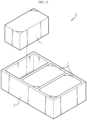
FIG. 1 , a conventional battery module includes a cell stack including abattery cell 100 and aswelling absorbing pad 200, and amodule housing 300 accommodating the cell stack. In the conventional battery module, anupper plate 300a and alower plate 300b of themodule housing 300 have an approximately flat shape. - When the
upper plate 300a and thelower plate 300b of themodule housing 300 have such a flat shape, theupper plate 300a and thelower plate 300b are bent upward and downward, respectively according to swelling of thebattery cell 100. - Due to bending of the
upper plate 300a and thelower plate 300b, the pressure of theupper plate 300a and thelower plate 300b with respect to thebattery cell 100 is relatively low in the central region of thebattery cell 100 and is relatively strong as approaching to the edge regions. - Accordingly, as the gas generated in the
battery cell 100 is concentrated in the central region of thebattery cell 100, the separator constituting the electrode assembly may show wrinkles, and it functions as a factor impeding the movement of electrons, thereby accelerating degradation of thebattery cell 100. - In addition, when the pressure is concentrated on the edge regions of the
battery cell 100, the expansion amount due to swelling in the central region is excessively large, which may cause tearing in the pouch module housing. - Therefore, there is a need for developing a battery module having a structure in which deviation of the pressure applied to the battery cell due to swelling is resolved and the bending rigidity of the module housing is improved at a position corresponding to the central region of the battery cell.
- The present disclosure is designed to solve the problems of the related art, and therefore the present disclosure is directed to providing a battery module housing having a structure in which deviation of the pressure applied to a battery cell due to swelling is resolved and the bending rigidity of the module housing is improved at a position corresponding to the central region of the battery cell.
- However, technical problems to be solved by the present disclosure are not limited to the above-described problems, and other problems not mentioned herein may be clearly understood by one of ordinary skill in the art from the following description of the present disclosure.
- In one aspect of the present disclosure, there is provided a battery module including a cell stack including a plurality of battery cells; and a module housing including a base plate covering a lower surface of the cell stack, a cover plate covering an upper surface of the cell stack, and a connector connecting the base plate and the cover plate, and accommodating the cell stack, wherein the base plate and the cover plate have a curved shape so that the central region thereof is located closer to the cell stack than the edge regions.
- The cell stack may further include a pair of swelling absorbing pads disposed at both outermost sides of the cell stack in a stacking direction.
- Each of the pair of swelling absorbing pads may have a shape in which the thickness of the central region is thinner than that of the edge regions.
- Each of the pair of swelling absorbing pads may have a stepped shape so that the surfaces facing the base plate and the cover plate become lower from the edge regions toward the central region.
- Each of the pair of swelling absorbing pads may have a curved shape so that the surfaces facing the base plate and the cover plate are in full contact with the base plate and the cover plate.
- The connector may include an elongation portion having a relatively higher elongation than the peripheral region.
- The elongation portion may correspond to a region made of a metal having a relatively low elongation compared to the peripheral region.
- The elongation portion may correspond to a region formed to be thinner than the peripheral region.
- Meanwhile, in another aspect of the present disclosure, there is provided a battery pack including a battery module according to an embodiment of the present disclosure.
- In another aspect of the present disclosure, there is provided a vehicle including a battery pack according to an embodiment of the present disclosure.
- According to an aspect of the present disclosure, it is possible to resolve deviation of the pressure applied to a battery cell due to swelling, and to improve the bending rigidity of the module housing at a position corresponding to the central region of the battery cell.
- The accompanying drawings illustrate a preferred embodiment of the present disclosure and together with the foregoing disclosure, serve to provide further understanding of the technical features of the present disclosure, and thus the present disclosure is not construed as being limited to the drawings.
-
FIG. 1 is a view illustrating a conventional battery module. -
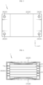
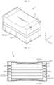
FIGS. 2 to 5 are views illustrating a battery module according to an embodiment of the present disclosure. -
FIGS. 6 and7 are views illustrating a shape in which a module housing is deformed due to swelling in a battery module according to an embodiment of the present disclosure. -
FIGS. 8 and 9 are views illustrating various shapes of a swelling absorbing pad in a battery module according to an embodiment of the present disclosure. -
FIGS. 10 to 12 are views illustrating a battery module according to another embodiment of the present disclosure. -
FIGS. 13 and14 are views illustrating a battery module according to still another embodiment of the present disclosure. -
FIG. 15 is a view illustrating a battery pack according to an embodiment of the present disclosure. -
FIG. 16 is a view illustrating a vehicle according to an embodiment of the present disclosure. - Hereinafter, preferred embodiments of the present disclosure will be described in detail with reference to the accompanying drawings. Prior to the description, it should be understood that the terms used in the specification and the appended claims should not be construed as limited to general and dictionary meanings, but interpreted based on the meanings and concepts corresponding to technical aspects of the present disclosure on the basis of the principle that the inventor is allowed to define terms appropriately for the best explanation. Therefore, the description proposed herein is just a preferable example for the purpose of illustrations only, not intended to limit the scope of the disclosure, so it should be understood that other equivalents and modifications could be made thereto without departing from the scope of the disclosure.
- A
battery module 1 according to an embodiment of the present disclosure will be described with reference toFIGS. 2 to 7 . Referring toFIGS. 2 to 7 , thebattery module 1 according to an embodiment of the present disclosure includes acell stack 10 and amodule housing 20. - The
cell stack 10 includes a plurality ofbattery cells 11. As thebattery cell 11, for example, a pouch-type battery cell may be applied. Thebattery cell 11 includes a pair of electrode leads 11a extending to the outside of thebattery cell 11 in a longitudinal direction (direction parallel to the X-axis) of thebattery cell 11. The pair of electrode leads 11a may be drawn out in the same direction or in opposite directions. The plurality ofbattery cells 11 are stacked to face each other in a vertical direction (direction parallel to the Z-axis). - The
cell stack 10 may further include a pair ofswelling absorbing pads 12 disposed at both outermost sides of thecell stack 10 in a stacking direction (direction parallel to the Z-axis). Theswelling absorbing pad 12 may be disposed between thebattery cells 11 adjacent to each other in addition to both outermost sides of thecell stack 10 in a stacking direction. Theswelling absorbing pad 12 may be compressed when swelling of thebattery cell 11 occurs due to repeated charge/discharge, thereby absorbing volume expansion of thebattery cell 11. - The
swelling absorbing pad 12 may have a flat shape like theswelling absorbing pad 200 provided in the conventional battery module shown inFIG. 1 , but may have a shape corresponding to amodule housing 20 having a curved shape as described below. The specific shape of theswelling absorbing pad 12 will be described later in detail after the description of themodule housing 20 of the present disclosure. - The
module housing 20 includes abase plate 21, acover plate 22, and aconnector 23. The module housing 20 accommodates thecell stack 10 therein. Themodule housing 20 may be made of a metal material to ensure rigidity. - The
base plate 21 covers a lower surface (surface parallel to the X-Y plane) of thecell stack 10. Thecover plate 22 covers an upper surface (surface parallel to the X-Y plane) of thecell stack 10. Theconnector 23 connects thebase plate 21 and thecover plate 22. - The
connector 23 may be integrally formed with thebase plate 21 and/or thecover plate 22. On the other hand, theconnector 23 may be formed separately from thebase plate 21 and/or thecover plate 22 and may be fastened to thebase plate 21 and/or thecover plate 22 by welding, bolting, or the like. - As shown in
FIGS. 2 and3 , theconnector 23 may have a shape including side plates forming a side surface of themodule housing 20. On the other hand, as shown inFIGS. 4 and5 , theconnector 23 may have a bar or beam shape for connecting and fixing thebase plate 21 and thecover plate 22. In this case, theconnector 23 may be fastened to four corner regions of each of thebase plate 21 and thecover plate 22. - The
base plate 21 and thecover plate 22 have a curved shape so that the central region thereof is located closer to thecell stack 10 than the edge regions. In the drawings of the present disclosure, there is shown only the case in which theswelling absorbing pad 12 is interposed between thebase plate 21 and thebattery cell 11 and between thecover plate 22 and thebattery cell 11, respectively. However, the present disclosure is not limited thereto, but also includes the case in which theswelling absorbing pad 12 is excluded. - Referring to
FIGS. 6 and7 , when swelling of thebattery cell 11 occurs, the central region of thebattery cell 11 comes into contact with thebase plate 21 and thecover plate 22 prior to the edge regions thereof due to the curved shape of thebase plate 21 and thecover plate 22. Therefore, the central region of thebattery cell 11 is pressurized first until the volume expansion of thebattery cell 11 occurs at a predetermined level or more due to swelling. When the volume expansion of thebattery cell 11 is made at a predetermined level or more due to swelling, the edge regions of thebattery cell 11 also come into contact with thebase plate 21 and thecover plate 22, thereby allowing pressure to be applied over the entire area of thebattery cell 11. - Meanwhile, when the
battery module 1 according to an embodiment of the present disclosure includes a pair of swelling absorbingpads 12 located at both outermost sides of thecell stack 10 in a stacking direction, each of the pair of swelling absorbingpads 12 may have a shape in which the thickness of the central region thereof is thinner than that of the edge regions thereof. In this case, the contact area between thecell stack 10 and thebase plate 21 and the contact area between thecell stack 10 and thecover plate 22 may be increased. Therefore, when the volume expansion occurs due to swelling of thebattery cell 11, uniform pressure may be applied over the entire area of thebattery cell 11. - Referring to
FIGS. 2 to 8 , each of the pair of swelling absorbingpads 12 may have a stepped shape so that a surface facing thebase plate 21 and thecover plate 22 is gradually lowering from the edge regions toward the central region. In a stepped shape formed on theswelling absorbing pad 12, one stepped structure may be provided as shown inFIGS. 2 to 7 , or a plurality of stepped structures may be provided as shown inFIG. 8 . - Referring to
FIG. 9 , unlike those shown inFIGS. 2 to 8 , each of the pair of swelling absorbingpads 12 has a curved shape in which a surface facing thebase plate 21 and thecover plate 22 is in full contact with thebase plate 21 and thecover plate 22. - As described above, the
battery module 1 according to an embodiment of the present disclosure includes thebase plate 21 and thecover plate 22 having a curved shape, and optionally includes the swelling absorbingpad 12 having a shape corresponding to thebase plate 21 and thecover plate 22, thereby allowing uniform pressure to be applied over the entire area of thebattery cell 11 when swelling occurs. - Next, the
battery module 1 according to another embodiment of the present disclosure will be described with reference toFIGS. 10 to 14 . Thebattery module 1 according to another embodiment of the present disclosure may include the same characteristics as thebattery module 1 according to the previous embodiment, except that theelongation portion 23a is provided in theconnector 23 as compared with thebattery module 1 according to the previous embodiment. Therefore, in describing thebattery module 1 according to another embodiment of the present disclosure, theconnector 23 may be intensively described, and a description overlapping with the previous embodiment may be omitted. - Referring to
FIGS. 10 to 14 , theconnector 23 includes anelongation portion 23a having a relatively higher elongation than the peripheral region. As shown inFIGS. 10 to 12 , theelongation portion 23a may correspond to a region made of a metal having a relatively lower elongation than the peripheral region. On the other hand, as shown inFIGS. 13 and14 , theelongation portion 23a may correspond to a region formed to be thinner than the peripheral region. - The
elongation portion 23a may be finely extended when a tensile force exceeding a predetermined level is applied to theconnector 23 as thebase plate 21 is subjected to a downward force and thecover plate 22 is subjected to an upward force due to the pressure caused by swelling. Due to the elongation of theelongation portion 23a, it is possible to prevent the pressure applied to thebattery cell 11 from being excessively increased. The metal material constituting theelongation portion 23a and/or the thickness of theelongation portion 23a may be appropriately selected in consideration of the magnitude of pressure according to swelling of thebattery cell 11. - As described above, the
battery module 1 according to another embodiment of the present disclosure may have a structure in which theconnector 23 may be finely extended when a tensile force exceeding a predetermined level is applied, in addition to a structure in which the pressure due to swelling may be uniformly applied over the entire area of thebattery cell 11. Therefore, in thebattery module 1 according to another embodiment of the present disclosure, it is possible to prevent damage to thebattery cell 11 due to excessively large pressure applied to thebattery cell 11. - Referring to
FIG. 15 , abattery pack 3 according to an embodiment of the present disclosure includes at least onebattery module 1 according to the present disclosure. Thebattery pack 3 may have a shape in which thebattery module 1 is accommodated in thepack housing 2. - Meanwhile, referring to
FIG. 16 , avehicle 4 according to an embodiment of the present disclosure includes thebattery pack 3 according to an embodiment of the present disclosure as described above. Thevehicle 4 may be, for example, an electric vehicle operated by the power from thebattery pack 3. - The present disclosure has been described in detail. However, it should be understood that the detailed description and specific examples, while indicating preferred embodiments of the disclosure, are given by way of illustration only, since various changes and modifications within the scope of the disclosure will become apparent to those skilled in the art from this detailed description.
-
- 1: battery module
- 2: pack housing
- 3: battery pack
- 4: vehicle
- 10: cell stack
- 11: battery cell
- 12: swelling absorbing pad
- 20: module housing
- 21: base plate
- 22: cover plate
- 23: connector
- 23a: elongation portion
Claims (10)
- A battery module comprising:a cell stack comprising a plurality of battery cells; anda module housing comprising a base plate covering a lower surface of the cell stack, a cover plate covering an upper surface of the cell stack, and a connector connecting the base plate and the cover plate, and accommodating the cell stack,wherein the base plate and the cover plate have a curved shape so that the central region thereof is located closer to the cell stack than the edge regions.
- The battery module according to claim 1,
wherein the cell stack further comprises a pair of swelling absorbing pads disposed at both outermost sides of the cell stack in a stacking direction. - The battery module according to claim 2,
wherein each of the pair of swelling absorbing pads has a shape in which the thickness of the central region is thinner than that of the edge regions. - The battery module according to claim 2,
wherein each of the pair of swelling absorbing pads has a stepped shape so that the surfaces facing the base plate and the cover plate become lower from the edge regions toward the central region. - The battery module according to claim 2,
wherein each of the pair of swelling absorbing pads has a curved shape so that the surfaces facing the base plate and the cover plate are in full contact with the base plate and the cover plate. - The battery module according to claim 1,
wherein the connector comprises an elongation portion having a relatively higher elongation than the peripheral region. - The battery module according to claim 6,
wherein the elongation portion corresponds to a region made of a metal having a relatively low elongation compared to the peripheral region. - The battery module according to claim 6,
wherein the elongation portion corresponds to a region formed to be thinner than the peripheral region. - A battery pack comprising a battery module according to any one of claims 1 to 8.
- A vehicle comprising a battery pack according to claim 9.
Applications Claiming Priority (2)
| Application Number | Priority Date | Filing Date | Title |
|---|---|---|---|
| KR1020210020137A KR102806373B1 (en) | 2021-02-15 | 2021-02-15 | A battery module having a structure in which even pressure can be applied when swelling occurs, and a battery pack and vehicle including the same |
| PCT/KR2022/002052 WO2022173249A2 (en) | 2021-02-15 | 2022-02-10 | Battery module having structure enabling uniform pressure to be applied during swelling, and battery pack and vehicle comprising same |
Publications (3)
| Publication Number | Publication Date |
|---|---|
| EP4181294A2 true EP4181294A2 (en) | 2023-05-17 |
| EP4181294A4 EP4181294A4 (en) | 2024-10-16 |
| EP4181294B1 EP4181294B1 (en) | 2026-04-01 |
Family
ID=82838038
Family Applications (1)
| Application Number | Title | Priority Date | Filing Date |
|---|---|---|---|
| EP22753009.4A Active EP4181294B1 (en) | 2021-02-15 | 2022-02-10 | Battery module having structure enabling uniform pressure to be applied during swelling, and battery pack and vehicle comprising same |
Country Status (6)
| Country | Link |
|---|---|
| US (1) | US20230387531A1 (en) |
| EP (1) | EP4181294B1 (en) |
| JP (1) | JP7543443B2 (en) |
| KR (1) | KR102806373B1 (en) |
| CN (1) | CN115668609A (en) |
| WO (1) | WO2022173249A2 (en) |
Families Citing this family (3)
| Publication number | Priority date | Publication date | Assignee | Title |
|---|---|---|---|---|
| JP7518048B2 (en) * | 2021-09-07 | 2024-07-17 | プライムプラネットエナジー&ソリューションズ株式会社 | Power storage device |
| KR20240070282A (en) * | 2022-11-14 | 2024-05-21 | 주식회사 엘지에너지솔루션 | Battery pack |
| DE102023132168B3 (en) | 2023-11-20 | 2025-04-30 | Dr. Ing. H.C. F. Porsche Aktiengesellschaft | Method for producing a cell module for a high-voltage battery and a cell module and a high-voltage battery |
Family Cites Families (12)
| Publication number | Priority date | Publication date | Assignee | Title |
|---|---|---|---|---|
| JPH11329373A (en) * | 1998-05-12 | 1999-11-30 | Furukawa Battery Co Ltd:The | Sealed lead-acid storage battery |
| JP2009182001A (en) * | 2008-01-29 | 2009-08-13 | Nisshin Steel Co Ltd | Cell stack structure |
| US8697275B2 (en) * | 2009-03-04 | 2014-04-15 | Samsung Sdi Co., Ltd. | Rechargeable battery having an extendable case region |
| JP6252216B2 (en) | 2014-02-07 | 2017-12-27 | 株式会社Soken | Assembled battery |
| JP2016035876A (en) * | 2014-08-04 | 2016-03-17 | 日産自動車株式会社 | Battery module |
| JP6258272B2 (en) * | 2015-08-11 | 2018-01-10 | 株式会社東芝 | Battery module |
| CN205508901U (en) * | 2016-03-14 | 2016-08-24 | 湖南大学 | Lithium ion battery concatenation formula layer unit frame and lithium ion battery module that constitutes thereof |
| KR102018721B1 (en) * | 2016-05-31 | 2019-09-09 | 주식회사 엘지화학 | Battery module, battery pack comprising the battery module and vehicle comprising the battery pack |
| KR102159347B1 (en) * | 2017-11-14 | 2020-09-23 | 주식회사 엘지화학 | Battery module having end plates pressurizing battery cells and extensible sensing housing parts |
| CN113243106B (en) | 2018-06-29 | 2022-11-01 | 华为技术有限公司 | Apparatus and method for intra prediction of prediction block of video image |
| KR102396437B1 (en) | 2019-06-25 | 2022-05-09 | 주식회사 엘지에너지솔루션 | Battery module and battery pack including the same |
| CN112201801B (en) * | 2020-10-30 | 2025-09-16 | 时代天源(深圳)科技有限公司 | Battery pressurizing device and battery pressurizing method |
-
2021
- 2021-02-15 KR KR1020210020137A patent/KR102806373B1/en active Active
-
2022
- 2022-02-10 CN CN202280004413.XA patent/CN115668609A/en active Pending
- 2022-02-10 JP JP2022574821A patent/JP7543443B2/en active Active
- 2022-02-10 US US18/032,336 patent/US20230387531A1/en active Pending
- 2022-02-10 EP EP22753009.4A patent/EP4181294B1/en active Active
- 2022-02-10 WO PCT/KR2022/002052 patent/WO2022173249A2/en not_active Ceased
Also Published As
| Publication number | Publication date |
|---|---|
| US20230387531A1 (en) | 2023-11-30 |
| WO2022173249A2 (en) | 2022-08-18 |
| EP4181294A4 (en) | 2024-10-16 |
| CN115668609A (en) | 2023-01-31 |
| JP2023528505A (en) | 2023-07-04 |
| JP7543443B2 (en) | 2024-09-02 |
| EP4181294B1 (en) | 2026-04-01 |
| KR102806373B1 (en) | 2025-05-09 |
| KR20220116815A (en) | 2022-08-23 |
| WO2022173249A3 (en) | 2022-10-06 |
Similar Documents
| Publication | Publication Date | Title |
|---|---|---|
| EP4181294A2 (en) | Battery module having structure enabling uniform pressure to be applied during swelling, and battery pack and vehicle comprising same | |
| US11769925B2 (en) | Battery module having initial pressing force reinforcing structure for cell assembly and method of manufacturing the same | |
| KR102848263B1 (en) | Secondary batteries, battery modules and devices using batteries as a power source | |
| KR102018721B1 (en) | Battery module, battery pack comprising the battery module and vehicle comprising the battery pack | |
| CN109962192A (en) | battery module | |
| KR102834536B1 (en) | Battery module comprising expansion relief unit | |
| KR102788645B1 (en) | Battery Pack | |
| US20230344053A1 (en) | Support structure | |
| EP3796420A1 (en) | Battery module and battery pack | |
| EP1808915B1 (en) | Conductive plate and secondary battery pack using conductive plate | |
| EP4037078B1 (en) | Battery module comprising constant-force spring, and battery pack comprising same | |
| EP4318749A1 (en) | Battery cell and electrical device | |
| WO2026081971A1 (en) | Battery case and vehicle | |
| EP4138189A1 (en) | Secondary battery module and method for manufacturing same | |
| EP4435960A1 (en) | Secondary battery having improved terminal structure | |
| JP7844292B2 (en) | All-solid-state battery assembly | |
| US20250007072A1 (en) | Battery pack | |
| JP7630097B2 (en) | Energy Storage Module | |
| KR20230174035A (en) | Battery cell fixing apparatus | |
| JP2025112373A (en) | Power storage device | |
| KR20240176325A (en) | Guide and spacer comprising the same | |
| KR20260008348A (en) | Battery device | |
| KR20260052531A (en) | Battery case and pouch type secondary battery comprising the same | |
| KR20260052509A (en) | Battery apparatus and manufacturing method of battery apparatus | |
| KR20240037049A (en) | Secondary battery and secondary battery module including the same |
Legal Events
| Date | Code | Title | Description |
|---|---|---|---|
| STAA | Information on the status of an ep patent application or granted ep patent |
Free format text: STATUS: THE INTERNATIONAL PUBLICATION HAS BEEN MADE |
|
| PUAI | Public reference made under article 153(3) epc to a published international application that has entered the european phase |
Free format text: ORIGINAL CODE: 0009012 |
|
| STAA | Information on the status of an ep patent application or granted ep patent |
Free format text: STATUS: REQUEST FOR EXAMINATION WAS MADE |
|
| 17P | Request for examination filed |
Effective date: 20230210 |
|
| AK | Designated contracting states |
Kind code of ref document: A2 Designated state(s): AL AT BE BG CH CY CZ DE DK EE ES FI FR GB GR HR HU IE IS IT LI LT LU LV MC MK MT NL NO PL PT RO RS SE SI SK SM TR |
|
| DAV | Request for validation of the european patent (deleted) | ||
| DAX | Request for extension of the european patent (deleted) | ||
| A4 | Supplementary search report drawn up and despatched |
Effective date: 20240912 |
|
| RIC1 | Information provided on ipc code assigned before grant |
Ipc: H01M 50/211 20210101ALI20240906BHEP Ipc: H01M 50/249 20210101ALI20240906BHEP Ipc: H01M 50/242 20210101AFI20240906BHEP |
|
| STAA | Information on the status of an ep patent application or granted ep patent |
Free format text: STATUS: EXAMINATION IS IN PROGRESS |
|
| 17Q | First examination report despatched |
Effective date: 20250509 |
|
| GRAP | Despatch of communication of intention to grant a patent |
Free format text: ORIGINAL CODE: EPIDOSNIGR1 |
|
| STAA | Information on the status of an ep patent application or granted ep patent |
Free format text: STATUS: GRANT OF PATENT IS INTENDED |
|
| INTG | Intention to grant announced |
Effective date: 20251031 |
|
| GRAS | Grant fee paid |
Free format text: ORIGINAL CODE: EPIDOSNIGR3 |
|
| GRAA | (expected) grant |
Free format text: ORIGINAL CODE: 0009210 |
|
| STAA | Information on the status of an ep patent application or granted ep patent |
Free format text: STATUS: THE PATENT HAS BEEN GRANTED |
|
| AK | Designated contracting states |
Kind code of ref document: B1 Designated state(s): AL AT BE BG CH CY CZ DE DK EE ES FI FR GB GR HR HU IE IS IT LI LT LU LV MC MK MT NL NO PL PT RO RS SE SI SK SM TR |
|
| P01 | Opt-out of the competence of the unified patent court (upc) registered |
Free format text: CASE NUMBER: UPC_APP_0006068_4181294/2026 Effective date: 20260219 |
|
| REG | Reference to a national code |
Ref country code: CH Ref legal event code: F10 Free format text: ST27 STATUS EVENT CODE: U-0-0-F10-F00 (AS PROVIDED BY THE NATIONAL OFFICE) Effective date: 20260401 Ref country code: GB Ref legal event code: FG4D |
|
| REG | Reference to a national code |
Ref country code: DE Ref legal event code: R096 Ref document number: 602022033545 Country of ref document: DE |
|
| REG | Reference to a national code |
Ref country code: IE Ref legal event code: FG4D |