EP4181269B1 - Expansion member for probe for charging and discharging battery - Google Patents
Expansion member for probe for charging and discharging battery Download PDFInfo
- Publication number
- EP4181269B1 EP4181269B1 EP21213338.3A EP21213338A EP4181269B1 EP 4181269 B1 EP4181269 B1 EP 4181269B1 EP 21213338 A EP21213338 A EP 21213338A EP 4181269 B1 EP4181269 B1 EP 4181269B1
- Authority
- EP
- European Patent Office
- Prior art keywords
- fluid
- battery
- probe
- expansion member
- unit
- Prior art date
- Legal status (The legal status is an assumption and is not a legal conclusion. Google has not performed a legal analysis and makes no representation as to the accuracy of the status listed.)
- Active
Links
Images


Classifications
-
- H—ELECTRICITY
- H01—ELECTRIC ELEMENTS
- H01M—PROCESSES OR MEANS, e.g. BATTERIES, FOR THE DIRECT CONVERSION OF CHEMICAL ENERGY INTO ELECTRICAL ENERGY
- H01M10/00—Secondary cells; Manufacture thereof
- H01M10/42—Methods or arrangements for servicing or maintenance of secondary cells or secondary half-cells
- H01M10/44—Methods for charging or discharging
- H01M10/446—Initial charging measures
-
- H—ELECTRICITY
- H01—ELECTRIC ELEMENTS
- H01M—PROCESSES OR MEANS, e.g. BATTERIES, FOR THE DIRECT CONVERSION OF CHEMICAL ENERGY INTO ELECTRICAL ENERGY
- H01M10/00—Secondary cells; Manufacture thereof
- H01M10/04—Construction or manufacture in general
-
- H—ELECTRICITY
- H02—GENERATION; CONVERSION OR DISTRIBUTION OF ELECTRIC POWER
- H02J—ELECTRIC POWER NETWORKS; CIRCUIT ARRANGEMENTS OR SYSTEMS FOR SUPPLYING OR DISTRIBUTING ELECTRIC POWER; SYSTEMS FOR STORING ELECTRIC ENERGY
- H02J7/00—Circuit arrangements for charging or discharging batteries or for supplying loads from batteries
- H02J7/70—Circuit arrangements for charging or discharging batteries or for supplying loads from batteries characterised by the mechanical construction
- H02J7/751—Circuit arrangements for charging or discharging batteries or for supplying loads from batteries characterised by the mechanical construction concerning the insertion or the connection of the batteries
-
- H—ELECTRICITY
- H01—ELECTRIC ELEMENTS
- H01M—PROCESSES OR MEANS, e.g. BATTERIES, FOR THE DIRECT CONVERSION OF CHEMICAL ENERGY INTO ELECTRICAL ENERGY
- H01M10/00—Secondary cells; Manufacture thereof
- H01M10/42—Methods or arrangements for servicing or maintenance of secondary cells or secondary half-cells
- H01M10/48—Accumulators combined with arrangements for measuring, testing or indicating the condition of cells, e.g. the level or density of the electrolyte
-
- H—ELECTRICITY
- H01—ELECTRIC ELEMENTS
- H01M—PROCESSES OR MEANS, e.g. BATTERIES, FOR THE DIRECT CONVERSION OF CHEMICAL ENERGY INTO ELECTRICAL ENERGY
- H01M50/00—Constructional details or processes of manufacture of the non-active parts of electrochemical cells other than fuel cells, e.g. hybrid cells
- H01M50/20—Mountings; Secondary casings or frames; Racks, modules or packs; Suspension devices; Shock absorbers; Transport or carrying devices; Holders
- H01M50/204—Racks, modules or packs for multiple batteries or multiple cells
- H01M50/207—Racks, modules or packs for multiple batteries or multiple cells characterised by their shape
- H01M50/209—Racks, modules or packs for multiple batteries or multiple cells characterised by their shape adapted for prismatic or rectangular cells
-
- H—ELECTRICITY
- H02—GENERATION; CONVERSION OR DISTRIBUTION OF ELECTRIC POWER
- H02J—ELECTRIC POWER NETWORKS; CIRCUIT ARRANGEMENTS OR SYSTEMS FOR SUPPLYING OR DISTRIBUTING ELECTRIC POWER; SYSTEMS FOR STORING ELECTRIC ENERGY
- H02J7/00—Circuit arrangements for charging or discharging batteries or for supplying loads from batteries
- H02J7/865—Battery or charger load switching, e.g. concurrent charging and load supply
-
- H—ELECTRICITY
- H02—GENERATION; CONVERSION OR DISTRIBUTION OF ELECTRIC POWER
- H02J—ELECTRIC POWER NETWORKS; CIRCUIT ARRANGEMENTS OR SYSTEMS FOR SUPPLYING OR DISTRIBUTING ELECTRIC POWER; SYSTEMS FOR STORING ELECTRIC ENERGY
- H02J7/00—Circuit arrangements for charging or discharging batteries or for supplying loads from batteries
- H02J7/90—Regulation of charging or discharging current or voltage
- H02J7/96—Regulation of charging or discharging current or voltage in response to battery voltage
-
- H—ELECTRICITY
- H01—ELECTRIC ELEMENTS
- H01M—PROCESSES OR MEANS, e.g. BATTERIES, FOR THE DIRECT CONVERSION OF CHEMICAL ENERGY INTO ELECTRICAL ENERGY
- H01M10/00—Secondary cells; Manufacture thereof
- H01M10/42—Methods or arrangements for servicing or maintenance of secondary cells or secondary half-cells
- H01M10/44—Methods for charging or discharging
- H01M10/445—Methods for charging or discharging in response to gas pressure
-
- Y—GENERAL TAGGING OF NEW TECHNOLOGICAL DEVELOPMENTS; GENERAL TAGGING OF CROSS-SECTIONAL TECHNOLOGIES SPANNING OVER SEVERAL SECTIONS OF THE IPC; TECHNICAL SUBJECTS COVERED BY FORMER USPC CROSS-REFERENCE ART COLLECTIONS [XRACs] AND DIGESTS
- Y02—TECHNOLOGIES OR APPLICATIONS FOR MITIGATION OR ADAPTATION AGAINST CLIMATE CHANGE
- Y02E—REDUCTION OF GREENHOUSE GAS [GHG] EMISSIONS, RELATED TO ENERGY GENERATION, TRANSMISSION OR DISTRIBUTION
- Y02E60/00—Enabling technologies; Technologies with a potential or indirect contribution to GHG emissions mitigation
- Y02E60/10—Energy storage using batteries
Definitions
- the present disclosure relates to an expansion member for a probe for battery charging and discharging and a probe including the same, and more particularly, to an expansion member for a probe of a charger and discharger, which can come into contact with posts provided on both sides of a prismatic battery.
- a rechargeable battery is a power source for a portable electronic device for information communication, such as a mobile phone, a tablet PC or a notebook computer, an electric bicycle, an electric vehicle, etc., and a demand for the rechargeable battery suddenly increases.
- a process of manufacturing the rechargeable battery may be basically divided into an electrode process, a stacking process, an activation process, a test process, etc.
- the activation process means a process of activating a stacked battery (or a battery cell) so that the stacked battery can be used. Specifically, during the activation process, the battery is charged and discharged by supplying a voltage and a current to the battery.
- the probe For the charging and discharging of the battery, after a probe including an electrode is brought into contact with the battery, a current or a voltage is supplied to the electrode included in the battery through the probe. Accordingly, the probe is commonly disposed at a position corresponding to the electrode of the battery.
- the battery is divided into a prismatic type, a pouch type and a cylindrical type.
- an electrode of the prismatic battery is commonly provided on the top of the battery.
- a probe for the charging and discharging of the battery is also disposed on the top of the battery.
- the electrode of the prismatic battery is provided on the side of the battery, the probe also needs to be disposed on the side of the battery.
- the probe is disposed on the side of the battery, it is necessary to efficiently dispose the probe on the side of the battery because there is a good possibility that the probe may interfere with the battery in an arrangement aspect.
- additional pressurization means for bringing the probe into contact with the battery is present, there is a problem in that a space occupied by the probe is increased.
- US 5 329 932 A discloses an apparatus for measuring respiration includes gauges comprised of a compliant tube, e.g., natural or silicone rubber filled with a conductive gel.
- a compliant tube e.g., natural or silicone rubber filled with a conductive gel.
- US 2015/171480 A1 teaches an apparatus for preventing battery overcharge, in which an installation space is formed between outer parts of at least two holders that enclose cells stacked within a battery.
- a fluid pouch is disposed within the installation space and contains a fluid therein.
- the present disclosure is intended to provide an expansion member included in a probe for battery charging and discharging, which enables a contact with an electrode of the battery without a separate pressurization apparatus.
- a probe which enables battery charging and discharging although an electrode of a prismatic battery is disposed on both sides of the prismatic battery which face each other.
- the invention provides an expansion member according to claim 1. Further developments of the invention are defined in the dependent claims.
- An expansion member for a probe for battery charging and discharging includes a first fluid accommodation part configured to form a space in which a fluid is introduced and stored and a fluid supply pipe equipped with a path along which the fluid is introduced and discharged and connected to the first fluid accommodation part.
- the first fluid accommodation part may include a first cover and a second cover. The first cover and the second cover may be bonded together to form a first fluid accommodation space in which the fluid is accommodated.
- the first fluid accommodation space may be surrounded by a first junction region in which the first cover and the second cover are bonded together.
- a penetration hole may be formed on the top of the first junction region.
- a probe for the charging and discharging of a prismatic battery is a probe for charging and discharging of a prismatic battery, including a contact point unit disposed on one side of the probe and equipped, on one surface thereof, with an electrode part for providing a current to the prismatic battery, an expansion member disposed on another surface of the contact point unit and configured to expand when a fluid is introduced therein so that an electrode part comes into contact with an electrode of the prismatic battery, a support unit disposed on another side of the probe and configured to support the expansion member, and a connection unit coupled with the support unit configured to limit a moving direction of the expansion member.
- the battery can be charged and discharged in accordance with a location of the electrode.
- an electrode of a battery can be charged and discharged without a separate pressurization apparatus for a contact with the electrode, such as a motor. Accordingly, space utilization can be improved because a space occupied by the motor for pressurization is obviated.
- a pressure value of the contact point unit coming into contact with the electrode can be adjusted by adjusting the amount of the introduced fluid without replacing a separate part.
- transverse direction used in the following description means a front side, rear side, left or right direction in the state in which a position in the up or down direction is not changed.
- perpendicular direction used in the following description means the up or down direction in the state in which a position in the front side, rear side, left or right direction is not changed.
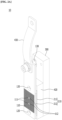
- FIG. 1 is a diagram illustrating a structure in which a probe for the charging and discharging of a prismatic battery according to the present disclosure is provided in plural and coupled with a plurality of batteries 1.
- the structure in which the probe for the charging and discharging of a prismatic battery according to an embodiment of the present disclosure is coupled with the plurality of batteries includes the battery 1, a probe 10, and a battery accommodation unit 20.
- An electrode of a conventional battery is disposed on the top of the battery, but an electrode of the battery 1 with which the probe 10 according to embodiments of the present disclosure comes into contact is disposed on both sides of the battery which face each other.
- the battery accommodation unit 20 forms a space in which one or more batteries 1 can be accommodated, and further includes fitting units protruded toward the inside thereof on both sides of the battery which face each other.
- the probe 10 may be fitted and coupled to the fitting units.
- FIG. 2a is a perspective view of the probe 10 for the charging and discharging of a prismatic battery according to the present disclosure.
- FIG. 2b is an exploded perspective view of FIG. 2a .
- FIG. 3a is a cross-sectional view of FIG. 2a .
- FIG. 3b is a diagram illustrating the state in which a fluid has been introduced into an expansion member 200 in FIG. 3a .
- the probe 10 includes a contact point unit 100, the expansion member 200, a support unit 300 and a connection unit 400.
- the contact point unit 100 is disposed on one side of the probe 10. A current may be applied to the contact point unit 100 by a shunt 430.
- the one side means a position neighboring an electrode of the battery 1.
- the contact point unit 100 comes into contact with the electrode of the battery 1 and supplies a current to the battery 1.
- the contact point unit 100 according to embodiments of the present disclosure selectively comes into contact with the electrode of the battery 1 depending on whether a fluid is introduced into the probe 10.
- the fluid may mean a gas or a liquid.
- the fluid may be air.
- the contact point unit 100 further includes an electrode part 110 and a guide hole 120.
- the electrode part 110 is disposed on one surface of the contact point unit 100, and includes a pin insertion hole 111 and a voltage sensing pin 112.
- the electrode part 110 is connected to the shunt 430 in a way to electrically communicate with the shunt.
- the electrode part 110 may be formed by performing surface processing on one surface of the contact point unit 100.
- the electrode part 110 may include a plurality of prominences and depressions formed on the contact point unit 100.
- an insulation unit 130 is disposed between the contact point unit 100 and the expansion member 200.
- One or more pin insertion holes 111 may be provided.
- the voltage sensing pin 112 is configured to detect a voltage of the battery 1 and disposed within the pin insertion hole 111.
- the voltage sensing pin 112 may be insulated from the electrode part 110.
- the voltage sensing pin 112 is isolated from the pin insertion hole 111 and disposed within the pin insertion hole 111.
- An electric wire connected to the voltage sensing pin 112 is disposed within the insulation unit 130, so that the voltage sensing pin 112 can be insulated from the electrode part 110.
- a controller 700 to be described later controls a power unit 500 to apply a current to the electrode part 110, and a detailed description thereof will be given later.
- the guide hole 120 is provided to be coupled with one end of a guide part 410.
- One or more guide holes 120 may be formed, and are formed in accordance with the number and positions of the guide part 410.
- a coupling member 411 of the guide part 410 may be protruded to the outside through one end of the guide part and fastened to the guide hole 120.
- the guide hole 120 is formed in an area of the contact point unit 100 other than the electrode part 110. If the guide hole 120 is formed in the electrode part 110, charging and discharging efficiency of the battery 1 may be reduced because a contact area between the electrode of the battery 1 and the electrode part 110 is reduced.
- the guide hole 120 has an internal diameter reduced from the battery 1 to the expansion member 200.
- An external diameter of the coupling member 411 is formed in accordance with the internal diameter of the guide hole 120.
- an external diameter of one end of the coupling member 411 is greater than an internal diameter of a portion close to the electrode of the battery 1 of the guide hole 120. In such a case, if a fluid leaks from the expansion member 200, the coupling member 411 may attract the contact point unit 100 so that the contact point unit 100 returns to a position before the fluid is introduced into the expansion member 200 because a restoring force of an elastic member (not illustrated) is directed toward a direction that becomes distant from the contact point unit 100.
- the expansion member 200 is a structure for enabling the contact point unit 100 to expand and come into contact with the electrode of the battery 1 when a fluid is introduced therein, and is disposed on a surface opposite to a surface with which the electrode of the battery 1 of the contact point unit 100 comes into contact.
- the support unit 300 is an element for supporting the expansion member 200, and is disposed on the other side of the probe 10.
- the other side means a position corresponding to the one side described in order to describe the position of the contact point unit 100.
- the support unit 300 is configured to fix a part of the probe 10 coupled with the fitting unit 21 of the battery accommodation unit 20 to be described later.
- the support unit 300 may include a given element for being coupled and fixed to the fitting unit 21 of the battery accommodation unit 20.
- a screw or a bolt may correspond to the given element.
- connection unit 400 is an element coupled with the support unit 300 configured to limit a moving direction of the expansion member 200, and a detailed description thereof is given later.
- FIG. 4 is a perspective view illustrating that only the expansion member 200 in FIG. 2a is separated and enlarged.
- the expansion member 200 further includes a fluid accommodation unit 210 and a fluid supply pipe 220.
- the fluid accommodation unit 210 includes a space in which a fluid introduced into the expansion member 200 is stored, and may be made of an elastic material.
- the fluid accommodation unit 210 further includes a first fluid accommodation part 211 and a second fluid accommodation part 212.
- the first fluid accommodation part 211 is connected to the fluid supply pipe 220 to be described later and is configured to enable the inflow and outflow of a fluid through the fluid supply pipe 220.
- the second fluid accommodation part 212 is disposed by being overlapped with the first fluid accommodation part 211.
- the size of a cross-sectional area of the second fluid accommodation part 212 may be smaller than the size of a cross-sectional area of the first fluid accommodation part 211. Specifically, it is preferred that the size of the second fluid accommodation part 212 corresponds to the size of the electrode part 110 so that the electrode of the battery 1 and the electrode part 110 are closely brought into contact with each other.
- a penetration hole 214 through which the coupling member 411 of the guide part 410 can pass is provided in the fluid accommodation unit 210.
- the number of penetration holes 214 and a position where the penetration hole 214 is formed may be determined in accordance with the number and position of the guide part 410, and a detailed description thereof is given later.
- the fluid supply pipe 220 is connected to the fluid accommodation unit 210 and configured to enable the inflow and outflow of a fluid in and from the fluid accommodation unit 210. Specifically, the fluid supply pipe 220 is connected to the first fluid accommodation part 211, so that a fluid flows in and out of the first fluid accommodation part 211.
- the fluid supply pipe 220 is isolated from the penetration area of the penetration hole 214.
- a fluid that flows in and out through the fluid supply pipe 220 may be air, for example, a non-conductive gas.
- FIG. 5 is a cross-sectional view of a cutting part taken along line A-A in FIG. 4 .
- FIG. 6 is a side cross-sectional view of the expansion member 200 in FIG. 4 .
- the first fluid accommodation part 211 forms a space in which a fluid may be introduced and stored, and further includes a first cover 2111 and a second cover 2112.
- the first cover 2111 and the second cover 2112 are bonded together in a way to form a first fluid accommodation space 2113 in which a fluid may be accommodated.
- the first fluid accommodation space 2113 is surrounded by a first junction region 2114 in which the first cover 2111 and the second cover 2112 are bonded together.
- the second fluid accommodation part 212 communicates with the first fluid accommodation part 211, and is disposed to overlap the first fluid accommodation part 211.
- the second fluid accommodation part 212 further includes a third cover 2121 and a fourth cover 2122.
- the third cover 2121 and the fourth cover 2122 are bonded together in a way to form a second fluid accommodation space 2123 in which a fluid may be accommodated.
- the second fluid accommodation space 2123 is surrounded by a second junction region 2124 in which the third cover 2121 and the fourth cover 2122 are bonded together.
- the penetration hole 214 is formed in the first junction region 2114 in which the first cover 2111 and the second cover 2112 are bonded together.
- the penetration hole 214 may be formed in pair. It is preferred that a pair of penetration holes 214 is disposed to face each other with the first fluid accommodated space 2113 interposed therebetween.
- the fluid supply pipe 220 may be buried in and fixed to the first junction region 2114.
- the fluid supply pipe 220 is fixed to the first junction region 2114, although a fluid is introduced into the fluid supply pipe 220, the fluid supply pipe 220 cannot be moved. Accordingly, the speed at which the fluid accommodation unit 210 is expanded can be predicted because the amount of a fluid introduced into the fluid accommodation unit 210 is constantly maintained.
- the fluid supply pipe 220 is not fixed to a specific location, when a fluid is introduced into the fluid supply pipe 220, the fluid supply pipe 220 may be moved. In this case, the amount of the fluid introduced into the fluid accommodation unit 210 may not be constant. Furthermore, if the fluid supply pipe 220 collides against another element while moving, an unexpected problem in that charging and discharging efficiency of the electrode of the battery 1 is reduced due to the expansion of the expansion member 200 to be described later may occur.
- FIG. 7 is a cross-sectional view of a cutting part taken along line B-B in FIG. 4 .
- the second fluid accommodation part 212 is coupled with the first fluid accommodation part 211 so that a fluid communicates with the second fluid accommodation part 212 and the first fluid accommodation part 211 through a fluid hole 213. Accordingly, when a fluid is introduced into the first fluid accommodation part 211, the fluid may be introduced into the second fluid accommodation part 212 through the fluid hole 213.
- the fluid hole 213 has been described as being illustrated in a cross section corresponding to line B-B in FIG. 4 , but embodiments of the present disclosure are not limited thereto.
- the fluid hole 213 may be formed in a given area between the first fluid accommodation part 211 and the second fluid accommodation part 212.
- the fluid supply pipe 220 is connected to the upper part of the first fluid accommodation part 211 and isolated from the penetration hole 214, but a position thereof is not essentially limited to the illustrated position.
- FIG. 8 is a cross-sectional view of FIG. 1 .
- FIG. 9 is a diagram illustrating the state in which a fluid has been introduced into the expansion member 200 in FIG. 8 .
- one side of the expansion member 200 is expanded in a direction that becomes distant from the other side of the expansion member 200 in the state in which the other side of the expansion member 200 has been fixed by the support unit 300.
- the contact point unit 100 coming into contact with the expansion member 200 becomes distant from the expansion member 200. Accordingly, if a fluid is introduced into the expansion member 200 to the maximum, the electrode part 110 of the contact point unit 100 and the electrode of the battery 1 come into contact with each other. Accordingly, when a current flows into the electrode part 110 of the contact point unit 100, the battery 1 may be charged and discharged.
- a pressure value of the contact point unit coming into contact with the electrode may be adjusted without replacing a separate part by adjusting the amount of a fluid introduced into the fluid accommodation unit 210 of the expansion member 200.
- the second fluid accommodation parts 212 may be disposed in parallel and connected to the first fluid accommodation part 211.
- a connection between the first fluid accommodation part 211 and the second fluid accommodation part 212 is performed by the fluid hole 213, and a description thereof has been given above and thus omitted.
- pressure of the electrode part 110 of the contact point unit 100 which may be applied to the electrode of the battery 1 may be increased because the amount of a fluid accommodated in the fluid accommodation unit 210 is increased. Accordingly, there is an effect in that precise charging and discharging can be performed because the electrode of the battery 1 and one surface of the contact point unit 100 can be closely brought into contact with each other by strong pressure.
- the illustrated embodiments include the guide part 410, a guide support part 420, etc.
- the guide part 410, the guide support part 420, etc. are described in detail later.
- the fluid accommodation unit 210 of the expansion member 200 includes only the first fluid accommodation part 211, as the first fluid accommodation part 2110 is expanded, the electrode part 110 of the contact point unit 100 and the electrode of the battery 1 may come into contact with each other.
- connection unit 400 is an element coupled with the support unit 300 and configured to limit a moving direction of the expansion member 200, and further includes the guide part 410, the guide support part 420 and the shunt 430.
- the guide part 410 has one end coupled with the contact point unit 100 and the other end coupled with the support unit 300.
- One or more guide parts 410 may be provided.
- the guide part 410 further includes the coupling member 411, a shaft 412 and an elastic member 413 therein.
- the shaft 412 is provided within the guide part 410 and forms a center axis of the guide part 410 in the length direction thereof.
- the elastic member 413 is provided within the guide part 410 and provided in a form to surround the shaft 412.
- the coupling member 411 is coupled with one end of the shaft 412 and protruded to the outside of the guide part 410. A detailed description of an effect attributable to the coupling of the elastic member 413 and the coupling member 411 is given later.
- the guide support part 420 includes a through hole 421 so that the guide part 410 can slide through the through hole 421 such that the moving direction of the guide part 410 is limited.
- the contact point unit 100 when air is introduced into the expansion member 200 and the expansion member 200 is expanded toward the electrode of the battery 1, the contact point unit 100 also moves toward the electrode of the battery 1, and the guide part 410 connected to the contact point unit 100 also moves. At this time, the guide part 410 slides and moves along the through hole 421.
- the contact point unit 100 no longer moves toward the electrode of the battery 1. Since the guide part 410 returns to its original position by a restoring force of the elastic member 413 included in the guide part 410, the contact point unit 100 coupled with the guide part 410 is also detached from the electrode of the battery 1 and thus may return to its original position along the guide part 410.
- the shunt 430 is formed in a curved form in which one side thereof is brought into contact and connected with the contact point unit 100 and the other side thereof is coupled with the support unit 300.
- the shunt 430 is flexibly configured. Accordingly, if the expansion member 200 is expanded due to the introduction of a fluid and the contact point unit 100 simultaneously moves toward the electrode of the battery 1, a shape of the shunt 430 may be deformed accordingly.
- FIG. 10 is a block diagram of a system including the probe for the charging and discharging of a prismatic battery according to the present disclosure.
- the system including the probe for the charging and discharging of a prismatic battery includes the probe 10, the power unit 500, a fluid supply unit 600 and the controller 700.
- the probe 10 is provided on both sides of each of one or more batteries 1 as described above, and may charge and discharge the batteries 1.
- the probe 10 further includes the contact point unit 100, the expansion member 200, the support unit 300 and the connection unit 400.
- the probe 10 and the elements constituting the probe are the same as those described above, and a description thereof is omitted.
- the power unit 500 may supply power to the probe 10.
- the power unit 500 may include a given element for power supply.
- the power supply is a well-known technology, and a detailed description thereof is omitted.
- the fluid supply unit 600 may supply a fluid to the probe 10.
- the fluid supply unit 600 may include a given element for supplying a fluid.
- the controller 700 may control the power supply of the power unit 500, and further includes a sensor unit 710.
- the controller 700 is connected to the sensor unit 710 in a way to electrically communicate therewith.
- the sensor unit 710 is configured to detect voltage information of the battery 1 through the voltage sensing pin 112 provided in the electrode part 110, and is connected to the controller 700 in a way to electrically communicate therewith.
- a method of detecting a voltage is a well-known technology, and a detailed description thereof is omitted.
- the controller 700 receives the voltage information and generates control information based on the received voltage information so that the power unit 500 supplies a current to the electrode part 110.
- FIG. 11 is a perspective view of a fixture including the probe for the charging and discharging of a prismatic battery according to the present disclosure.
- the fixture including the probe for the charging and discharging of a prismatic battery includes the probe 10, a power cable 800 and a fluid manifold 900.
- the probe 10 is disposed in plural at given intervals.
- the support unit 300 and shunt 430 of the probe 10 are coupled and fixed to a frame 30.
- the probe 10 and the elements constituting the probe are the same as those described above, and a description thereof is omitted.
- the frame 30 further includes a first frame 31 and a second frame 32, and a detailed description of the first frame 31 and the second frame 32 is given later.
- the power cable 800 is an element for supplying a current to the probe 10. To this end, the power cable 800 is connected to the shunt 430 in a way to electrically communicate therewith.
- the fluid manifold 900 is configured to supply a fluid to the probe 10, and is disposed in plural at given intervals.
- the fluid manifolds 900 are coupled and fixed to the frames 30.
- FIG. 12 is a cross-sectional view of FIG. 11 .
- the shunt 430 is coupled with the first frame 31.
- the support unit 300 is coupled with the second frame 32.
- the fluid manifold 900 to be described later is disposed on the top of the second frame 32.
- FIG. 13 is an enlarged perspective view of FIG. 11 .
- the probe 10 is disposed in plural at given intervals.
- a plurality of the shunts 430 is also coupled with the first frames 31, respectively, at given intervals.
- Each of the shunts 430 may be coupled with the same surface of the first frame 31.
- a plurality of the shunts 430 is alternately coupled with surfaces of the first frames 31 which face each other.
- the power cable 800 is connected to the shunt 430 in a way to electrically communicate therewith as described above.
- the power cable 800 is thick so that a high voltage current can flow into the power cable 800. Accordingly, if the shunts 430 are coupled with only the same surfaces of the first frames 31, an installation interval between the probes 10 needs to be wide.
- FIG. 14 is an enlarged perspective view of FIG. 11 , which is viewed at another angle.
- the fluid manifold 900 is configured to supply a fluid to the probe 10.
- one end of a fluid cable (not illustrated) and the fluid manifold 900 are coupled together.
- the fluid manifold 900 is configured to store a fluid introduced therein through the fluid cable (not illustrated) and to supply the stored fluid to each of the fluid supply pipes 220 of the plurality of probes 10. Accordingly, the expansion member 200 of the probe 10 may be expanded.
- the fluid manifold 900 may be disposed in the second frame 32 at given intervals. In this case, surfaces of the fluid manifold 900 and another adjacent fluid manifold 900, which face each other, may be connected by a connection pipe 910. When a fluid is introduced into the fluid manifold 900 with which the fluid cable (not illustrated) is coupled, the fluid communicates with an adjacent fluid manifold 900 through the connection pipe 910.
Landscapes
- Engineering & Computer Science (AREA)
- Chemical & Material Sciences (AREA)
- Chemical Kinetics & Catalysis (AREA)
- Electrochemistry (AREA)
- General Chemical & Material Sciences (AREA)
- Power Engineering (AREA)
- Manufacturing & Machinery (AREA)
- Secondary Cells (AREA)
Description
- The present disclosure relates to an expansion member for a probe for battery charging and discharging and a probe including the same, and more particularly, to an expansion member for a probe of a charger and discharger, which can come into contact with posts provided on both sides of a prismatic battery.
- In general, a rechargeable battery is a power source for a portable electronic device for information communication, such as a mobile phone, a tablet PC or a notebook computer, an electric bicycle, an electric vehicle, etc., and a demand for the rechargeable battery suddenly increases.
- A process of manufacturing the rechargeable battery may be basically divided into an electrode process, a stacking process, an activation process, a test process, etc. The activation process means a process of activating a stacked battery (or a battery cell) so that the stacked battery can be used. Specifically, during the activation process, the battery is charged and discharged by supplying a voltage and a current to the battery.
- For the charging and discharging of the battery, after a probe including an electrode is brought into contact with the battery, a current or a voltage is supplied to the electrode included in the battery through the probe. Accordingly, the probe is commonly disposed at a position corresponding to the electrode of the battery.
- The battery is divided into a prismatic type, a pouch type and a cylindrical type. Among them, an electrode of the prismatic battery is commonly provided on the top of the battery. In this case, a probe for the charging and discharging of the battery is also disposed on the top of the battery. If the electrode of the prismatic battery is provided on the side of the battery, the probe also needs to be disposed on the side of the battery. However, if the probe is disposed on the side of the battery, it is necessary to efficiently dispose the probe on the side of the battery because there is a good possibility that the probe may interfere with the battery in an arrangement aspect. In particular, if additional pressurization means for bringing the probe into contact with the battery is present, there is a problem in that a space occupied by the probe is increased.
- Contents described in "Background Art" help understanding of the background of the present disclosure, and may include contents that are not disclosed conventional technologies.
-
US 5 329 932 A discloses an apparatus for measuring respiration includes gauges comprised of a compliant tube, e.g., natural or silicone rubber filled with a conductive gel. -
US 2015/171480 A1 teaches an apparatus for preventing battery overcharge, in which an installation space is formed between outer parts of at least two holders that enclose cells stacked within a battery. A fluid pouch is disposed within the installation space and contains a fluid therein. -
Korean Patent No. 10-2131506 (July 1, 2020 - The present disclosure is intended to provide an expansion member included in a probe for battery charging and discharging, which enables a contact with an electrode of the battery without a separate pressurization apparatus.
- Furthermore, a probe is described which enables battery charging and discharging although an electrode of a prismatic battery is disposed on both sides of the prismatic battery which face each other.
- Objects to be solved by the present disclosure are not limited to the aforementioned objects, and the other objects not described above may be evidently understood from the following description by those skilled in the art.
- The invention provides an expansion member according to
claim 1. Further developments of the invention are defined in the dependent claims. - An expansion member for a probe for battery charging and discharging according to an embodiment of the present disclosure includes a first fluid accommodation part configured to form a space in which a fluid is introduced and stored and a fluid supply pipe equipped with a path along which the fluid is introduced and discharged and connected to the first fluid accommodation part. The first fluid accommodation part may include a first cover and a second cover. The first cover and the second cover may be bonded together to form a first fluid accommodation space in which the fluid is accommodated. The first fluid accommodation space may be surrounded by a first junction region in which the first cover and the second cover are bonded together. A penetration hole may be formed on the top of the first junction region.
- A probe for the charging and discharging of a prismatic battery is a probe for charging and discharging of a prismatic battery, including a contact point unit disposed on one side of the probe and equipped, on one surface thereof, with an electrode part for providing a current to the prismatic battery, an expansion member disposed on another surface of the contact point unit and configured to expand when a fluid is introduced therein so that an electrode part comes into contact with an electrode of the prismatic battery, a support unit disposed on another side of the probe and configured to support the expansion member, and a connection unit coupled with the support unit configured to limit a moving direction of the expansion member.
- According to the present disclosure, the following effects may be obtained.
- First, if an electrode of a battery is disposed on both sides of the battery which face each other, the battery can be charged and discharged in accordance with a location of the electrode.
- Furthermore, since the expansion member is provided, an electrode of a battery can be charged and discharged without a separate pressurization apparatus for a contact with the electrode, such as a motor. Accordingly, space utilization can be improved because a space occupied by the motor for pressurization is obviated.
- Furthermore, if a fluid is introduced into the expansion member, as the expansion member expands, the contact point unit comes into contact with an electrode of a battery. Accordingly, a pressure value of the contact point unit coming into contact with the electrode can be adjusted by adjusting the amount of the introduced fluid without replacing a separate part.
- Furthermore, if a plurality of probes is fixed, more battery cells can be simultaneously charged and discharged because an interval between the probes can be more narrowed.
- Effects of the present disclosure are not limited to the aforementioned effects, and effects not described above may be evidently understood from the following description by those skilled in the art.
-
-
FIG. 1 is a diagram illustrating a structure in which a probe for the charging and discharging of a prismatic battery according to the present disclosure is provided in plural and coupled with a plurality of batteries. -
FIG. 2a is a perspective view of the probe for the charging and discharging of a prismatic battery according to the present disclosure. -
FIG. 2b is an exploded perspective view ofFIG. 2a . -
FIG. 3a is a cross-sectional view ofFIG. 2a . -
FIG. 3b is a diagram illustrating the state in which a fluid has been introduced into an expansion member inFIG. 3a . -
FIG. 4 is a perspective view illustrating that only the expansion member inFIG. 2a is separated and enlarged. -
FIG. 5 is a cross-sectional view of a cutting part taken along line A-A inFIG. 4 . -
FIG. 6 is a side cross-sectional view of the expansion member inFIG. 4 . -
FIG. 7 is a cross-sectional view of a cutting part taken along line B-B inFIG. 4 . -
FIG. 8 is a cross-sectional view ofFIG. 1 . -
FIG. 9 is a diagram illustrating the state in which a fluid has been introduced into the expansion member inFIG. 8 . -
FIG. 10 is a block diagram of a system including the probe for the charging and discharging of a prismatic battery according to the present disclosure. -
FIG. 11 is a perspective view of a fixture including the probe for the charging and discharging of a prismatic battery according to the present disclosure. -
FIG. 12 is a cross-sectional view ofFIG. 11 . -
FIG. 13 is an enlarged perspective view ofFIG. 11 . -
FIG. 14 is an enlarged perspective view ofFIG. 11 , which is viewed at another angle. - Advantages and characteristics of the present disclosure and a method for achieving the advantages and characteristics will become apparent from the embodiments described in detail in conjunction with the accompanying drawings. However, the present disclosure is not limited to the disclosed embodiments, but may be implemented in various different forms. The embodiments are provided to only complete the present disclosure and to fully notify a person having ordinary knowledge in the art to which the present disclosure pertains of the category of the present disclosure. The disclosure is defined by the category of the claims.
- Terms used herein are used to describe specific embodiments and are not intended to limit the present disclosure. Furthermore, an expression of the singular number used in this specification may include an expression of the plural number unless clearly defined otherwise in the context.
- The term "includes" and/or "including" used in this specification does not exclude the presence or addition of one or more other elements in addition to a mentioned element.
- "and/or" used in this specification includes each of mentioned elements and all combinations of one or more of the mentioned elements. Although the terms "first", "second", etc. are used to describe various elements, these elements are not limited by these terms. These terms are merely used to distinguish between one element and another element. Accordingly, a first element mentioned hereinafter may be a second element within the technical teaching of the present disclosure.
- A term "transverse direction" used in the following description means a front side, rear side, left or right direction in the state in which a position in the up or down direction is not changed. A term "perpendicular direction" used in the following description means the up or down direction in the state in which a position in the front side, rear side, left or right direction is not changed.
- The drawings are merely for enabling the spirit of the present disclosure to be understood, and it should not be interpreted that the scope of the present disclosure is limited by the drawings. Furthermore, in the drawings, a relative thickness or length or a relative size may be enlarged for convenience and the clarity of description. The same reference numerals refer to the same elements throughout the specification.
- Hereinafter, embodiments of the present disclosure are described in detail with reference to the accompanying drawings.
-
FIG. 1 is a diagram illustrating a structure in which a probe for the charging and discharging of a prismatic battery according to the present disclosure is provided in plural and coupled with a plurality ofbatteries 1. - Referring to
FIG. 1 , the structure in which the probe for the charging and discharging of a prismatic battery according to an embodiment of the present disclosure is coupled with the plurality of batteries includes thebattery 1, aprobe 10, and abattery accommodation unit 20. - An electrode of a conventional battery is disposed on the top of the battery, but an electrode of the
battery 1 with which theprobe 10 according to embodiments of the present disclosure comes into contact is disposed on both sides of the battery which face each other. - The
battery accommodation unit 20 forms a space in which one ormore batteries 1 can be accommodated, and further includes fitting units protruded toward the inside thereof on both sides of the battery which face each other. Theprobe 10 may be fitted and coupled to the fitting units. -
FIG. 2a is a perspective view of theprobe 10 for the charging and discharging of a prismatic battery according to the present disclosure.FIG. 2b is an exploded perspective view ofFIG. 2a .FIG. 3a is a cross-sectional view ofFIG. 2a .FIG. 3b is a diagram illustrating the state in which a fluid has been introduced into anexpansion member 200 inFIG. 3a . - Referring to
FIGS. 2a ,2b ,3a and 3b , theprobe 10 includes acontact point unit 100, theexpansion member 200, asupport unit 300 and a connection unit 400. - The
contact point unit 100 is disposed on one side of theprobe 10. A current may be applied to thecontact point unit 100 by ashunt 430. In this case, the one side means a position neighboring an electrode of thebattery 1. - The
contact point unit 100 comes into contact with the electrode of thebattery 1 and supplies a current to thebattery 1. Thecontact point unit 100 according to embodiments of the present disclosure selectively comes into contact with the electrode of thebattery 1 depending on whether a fluid is introduced into theprobe 10. The fluid may mean a gas or a liquid. For example, the fluid may be air. - The
contact point unit 100 further includes anelectrode part 110 and aguide hole 120. - The
electrode part 110 is disposed on one surface of thecontact point unit 100, and includes apin insertion hole 111 and avoltage sensing pin 112. Theelectrode part 110 is connected to theshunt 430 in a way to electrically communicate with the shunt. - According to embodiments, the
electrode part 110 may be formed by performing surface processing on one surface of thecontact point unit 100. For example, theelectrode part 110 may include a plurality of prominences and depressions formed on thecontact point unit 100. - In order to prevent a short circuit in the
electrode part 110, aninsulation unit 130 is disposed between thecontact point unit 100 and theexpansion member 200. - One or more pin insertion holes 111 may be provided.
- The
voltage sensing pin 112 is configured to detect a voltage of thebattery 1 and disposed within thepin insertion hole 111. - According to an illustrated embodiment, the
voltage sensing pin 112 may be insulated from theelectrode part 110. For example, thevoltage sensing pin 112 is isolated from thepin insertion hole 111 and disposed within thepin insertion hole 111. An electric wire connected to thevoltage sensing pin 112 is disposed within theinsulation unit 130, so that thevoltage sensing pin 112 can be insulated from theelectrode part 110. - When the
voltage sensing pin 112 detects a voltage of thebattery 1, acontroller 700 to be described later controls apower unit 500 to apply a current to theelectrode part 110, and a detailed description thereof will be given later. - The
guide hole 120 is provided to be coupled with one end of aguide part 410. One or more guide holes 120 may be formed, and are formed in accordance with the number and positions of theguide part 410. - A
coupling member 411 of theguide part 410 may be protruded to the outside through one end of the guide part and fastened to theguide hole 120. - The
guide hole 120 is formed in an area of thecontact point unit 100 other than theelectrode part 110. If theguide hole 120 is formed in theelectrode part 110, charging and discharging efficiency of thebattery 1 may be reduced because a contact area between the electrode of thebattery 1 and theelectrode part 110 is reduced. - Furthermore, in the illustrated embodiment, it is preferred that the
guide hole 120 has an internal diameter reduced from thebattery 1 to theexpansion member 200. An external diameter of thecoupling member 411 is formed in accordance with the internal diameter of theguide hole 120. - It is preferred that an external diameter of one end of the
coupling member 411 is greater than an internal diameter of a portion close to the electrode of thebattery 1 of theguide hole 120. In such a case, if a fluid leaks from theexpansion member 200, thecoupling member 411 may attract thecontact point unit 100 so that thecontact point unit 100 returns to a position before the fluid is introduced into theexpansion member 200 because a restoring force of an elastic member (not illustrated) is directed toward a direction that becomes distant from thecontact point unit 100. - The
expansion member 200 is a structure for enabling thecontact point unit 100 to expand and come into contact with the electrode of thebattery 1 when a fluid is introduced therein, and is disposed on a surface opposite to a surface with which the electrode of thebattery 1 of thecontact point unit 100 comes into contact. - The
support unit 300 is an element for supporting theexpansion member 200, and is disposed on the other side of theprobe 10. In this case, the other side means a position corresponding to the one side described in order to describe the position of thecontact point unit 100. - The
support unit 300 is configured to fix a part of theprobe 10 coupled with thefitting unit 21 of thebattery accommodation unit 20 to be described later. - The
support unit 300 may include a given element for being coupled and fixed to thefitting unit 21 of thebattery accommodation unit 20. For example, a screw or a bolt may correspond to the given element. - The connection unit 400 is an element coupled with the
support unit 300 configured to limit a moving direction of theexpansion member 200, and a detailed description thereof is given later. -
FIG. 4 is a perspective view illustrating that only theexpansion member 200 inFIG. 2a is separated and enlarged. - Referring to
FIG. 4 , theexpansion member 200 further includes afluid accommodation unit 210 and afluid supply pipe 220. - The
fluid accommodation unit 210 includes a space in which a fluid introduced into theexpansion member 200 is stored, and may be made of an elastic material. - The
fluid accommodation unit 210 further includes a firstfluid accommodation part 211 and a secondfluid accommodation part 212. - The first
fluid accommodation part 211 is connected to thefluid supply pipe 220 to be described later and is configured to enable the inflow and outflow of a fluid through thefluid supply pipe 220. - The second
fluid accommodation part 212 is disposed by being overlapped with the firstfluid accommodation part 211. - The size of a cross-sectional area of the second
fluid accommodation part 212 may be smaller than the size of a cross-sectional area of the firstfluid accommodation part 211. Specifically, it is preferred that the size of the secondfluid accommodation part 212 corresponds to the size of theelectrode part 110 so that the electrode of thebattery 1 and theelectrode part 110 are closely brought into contact with each other. - Furthermore, a
penetration hole 214 through which thecoupling member 411 of theguide part 410 can pass is provided in thefluid accommodation unit 210. - The number of penetration holes 214 and a position where the
penetration hole 214 is formed may be determined in accordance with the number and position of theguide part 410, and a detailed description thereof is given later. - The
fluid supply pipe 220 is connected to thefluid accommodation unit 210 and configured to enable the inflow and outflow of a fluid in and from thefluid accommodation unit 210. Specifically, thefluid supply pipe 220 is connected to the firstfluid accommodation part 211, so that a fluid flows in and out of the firstfluid accommodation part 211. - The
fluid supply pipe 220 is isolated from the penetration area of thepenetration hole 214. - A fluid that flows in and out through the
fluid supply pipe 220 may be air, for example, a non-conductive gas. -
FIG. 5 is a cross-sectional view of a cutting part taken along line A-A inFIG. 4 .FIG. 6 is a side cross-sectional view of theexpansion member 200 inFIG. 4 . - Referring to
FIGS. 5 and6 , the firstfluid accommodation part 211 forms a space in which a fluid may be introduced and stored, and further includes afirst cover 2111 and asecond cover 2112. - The
first cover 2111 and thesecond cover 2112 are bonded together in a way to form a firstfluid accommodation space 2113 in which a fluid may be accommodated. - The first
fluid accommodation space 2113 is surrounded by afirst junction region 2114 in which thefirst cover 2111 and thesecond cover 2112 are bonded together. - The second
fluid accommodation part 212 communicates with the firstfluid accommodation part 211, and is disposed to overlap the firstfluid accommodation part 211. The secondfluid accommodation part 212 further includes athird cover 2121 and afourth cover 2122. - The
third cover 2121 and thefourth cover 2122 are bonded together in a way to form a secondfluid accommodation space 2123 in which a fluid may be accommodated. - The second
fluid accommodation space 2123 is surrounded by asecond junction region 2124 in which thethird cover 2121 and thefourth cover 2122 are bonded together. - The
penetration hole 214 is formed in thefirst junction region 2114 in which thefirst cover 2111 and thesecond cover 2112 are bonded together. - The
penetration hole 214 may be formed in pair. It is preferred that a pair of penetration holes 214 is disposed to face each other with the first fluid accommodatedspace 2113 interposed therebetween. - Referring to
FIGS. 4 and5 together, thefluid supply pipe 220 may be buried in and fixed to thefirst junction region 2114. - If the
fluid supply pipe 220 is fixed to thefirst junction region 2114, although a fluid is introduced into thefluid supply pipe 220, thefluid supply pipe 220 cannot be moved. Accordingly, the speed at which thefluid accommodation unit 210 is expanded can be predicted because the amount of a fluid introduced into thefluid accommodation unit 210 is constantly maintained. - If the
fluid supply pipe 220 is not fixed to a specific location, when a fluid is introduced into thefluid supply pipe 220, thefluid supply pipe 220 may be moved. In this case, the amount of the fluid introduced into thefluid accommodation unit 210 may not be constant. Furthermore, if thefluid supply pipe 220 collides against another element while moving, an unexpected problem in that charging and discharging efficiency of the electrode of thebattery 1 is reduced due to the expansion of theexpansion member 200 to be described later may occur. -
FIG. 7 is a cross-sectional view of a cutting part taken along line B-B inFIG. 4 . - Referring to
FIG. 7 , the secondfluid accommodation part 212 is coupled with the firstfluid accommodation part 211 so that a fluid communicates with the secondfluid accommodation part 212 and the firstfluid accommodation part 211 through afluid hole 213. Accordingly, when a fluid is introduced into the firstfluid accommodation part 211, the fluid may be introduced into the secondfluid accommodation part 212 through thefluid hole 213. - The
fluid hole 213 has been described as being illustrated in a cross section corresponding to line B-B inFIG. 4 , but embodiments of the present disclosure are not limited thereto. Thefluid hole 213 may be formed in a given area between the firstfluid accommodation part 211 and the secondfluid accommodation part 212. - In the illustrated embodiment, the
fluid supply pipe 220 is connected to the upper part of the firstfluid accommodation part 211 and isolated from thepenetration hole 214, but a position thereof is not essentially limited to the illustrated position. -
FIG. 8 is a cross-sectional view ofFIG. 1 .FIG. 9 is a diagram illustrating the state in which a fluid has been introduced into theexpansion member 200 inFIG. 8 . - Referring to
FIGS. 8 and9 , when air is introduced into theexpansion member 200, one side of theexpansion member 200 is expanded in a direction that becomes distant from the other side of theexpansion member 200 in the state in which the other side of theexpansion member 200 has been fixed by thesupport unit 300. - As one side of the
expansion member 200 is expanded, thecontact point unit 100 coming into contact with theexpansion member 200 becomes distant from theexpansion member 200. Accordingly, if a fluid is introduced into theexpansion member 200 to the maximum, theelectrode part 110 of thecontact point unit 100 and the electrode of thebattery 1 come into contact with each other. Accordingly, when a current flows into theelectrode part 110 of thecontact point unit 100, thebattery 1 may be charged and discharged. - A pressure value of the contact point unit coming into contact with the electrode may be adjusted without replacing a separate part by adjusting the amount of a fluid introduced into the
fluid accommodation unit 210 of theexpansion member 200. - According to an embodiment of the present disclosure, the second
fluid accommodation parts 212 may be disposed in parallel and connected to the firstfluid accommodation part 211. A connection between the firstfluid accommodation part 211 and the secondfluid accommodation part 212 is performed by thefluid hole 213, and a description thereof has been given above and thus omitted. If the plurality offluid accommodation units 210 is connected in parallel, pressure of theelectrode part 110 of thecontact point unit 100 which may be applied to the electrode of thebattery 1 may be increased because the amount of a fluid accommodated in thefluid accommodation unit 210 is increased. Accordingly, there is an effect in that precise charging and discharging can be performed because the electrode of thebattery 1 and one surface of thecontact point unit 100 can be closely brought into contact with each other by strong pressure. - Furthermore, for a close contact, if a fluid is introduced into the
expansion member 200 as described above and thecontact point unit 100 becomes close to the electrode of thebattery 1, it is preferred that a cross section of one surface of thecontact point unit 100 is moved and maintained to be perpendicular to a moving direction of thecontact point unit 100. To this end, the illustrated embodiments include theguide part 410, aguide support part 420, etc. Theguide part 410, theguide support part 420, etc. are described in detail later. - Although the
fluid accommodation unit 210 of theexpansion member 200 includes only the firstfluid accommodation part 211, as the first fluid accommodation part 2110 is expanded, theelectrode part 110 of thecontact point unit 100 and the electrode of thebattery 1 may come into contact with each other. - The connection unit 400 is an element coupled with the
support unit 300 and configured to limit a moving direction of theexpansion member 200, and further includes theguide part 410, theguide support part 420 and theshunt 430. - The
guide part 410 has one end coupled with thecontact point unit 100 and the other end coupled with thesupport unit 300. One ormore guide parts 410 may be provided. - The
guide part 410 further includes thecoupling member 411, ashaft 412 and anelastic member 413 therein. - The
shaft 412 is provided within theguide part 410 and forms a center axis of theguide part 410 in the length direction thereof. Theelastic member 413 is provided within theguide part 410 and provided in a form to surround theshaft 412. Thecoupling member 411 is coupled with one end of theshaft 412 and protruded to the outside of theguide part 410. A detailed description of an effect attributable to the coupling of theelastic member 413 and thecoupling member 411 is given later. - The
guide support part 420 includes a throughhole 421 so that theguide part 410 can slide through the throughhole 421 such that the moving direction of theguide part 410 is limited. - In the illustrated embodiment, when air is introduced into the
expansion member 200 and theexpansion member 200 is expanded toward the electrode of thebattery 1, thecontact point unit 100 also moves toward the electrode of thebattery 1, and theguide part 410 connected to thecontact point unit 100 also moves. At this time, theguide part 410 slides and moves along the throughhole 421. - In contrast, when a fluid is discharged from the
expansion member 200, thecontact point unit 100 no longer moves toward the electrode of thebattery 1. Since theguide part 410 returns to its original position by a restoring force of theelastic member 413 included in theguide part 410, thecontact point unit 100 coupled with theguide part 410 is also detached from the electrode of thebattery 1 and thus may return to its original position along theguide part 410. - The
shunt 430 is formed in a curved form in which one side thereof is brought into contact and connected with thecontact point unit 100 and the other side thereof is coupled with thesupport unit 300. Theshunt 430 is flexibly configured. Accordingly, if theexpansion member 200 is expanded due to the introduction of a fluid and thecontact point unit 100 simultaneously moves toward the electrode of thebattery 1, a shape of theshunt 430 may be deformed accordingly. -
FIG. 10 is a block diagram of a system including the probe for the charging and discharging of a prismatic battery according to the present disclosure. - Referring to
FIG. 10 , the system including the probe for the charging and discharging of a prismatic battery includes theprobe 10, thepower unit 500, afluid supply unit 600 and thecontroller 700. - The
probe 10 is provided on both sides of each of one ormore batteries 1 as described above, and may charge and discharge thebatteries 1. Theprobe 10 further includes thecontact point unit 100, theexpansion member 200, thesupport unit 300 and the connection unit 400. - The
probe 10 and the elements constituting the probe are the same as those described above, and a description thereof is omitted. - The
power unit 500 may supply power to theprobe 10. Thepower unit 500 may include a given element for power supply. The power supply is a well-known technology, and a detailed description thereof is omitted. - The
fluid supply unit 600 may supply a fluid to theprobe 10. Thefluid supply unit 600 may include a given element for supplying a fluid. - The
controller 700 may control the power supply of thepower unit 500, and further includes asensor unit 710. Thecontroller 700 is connected to thesensor unit 710 in a way to electrically communicate therewith. - The
sensor unit 710 is configured to detect voltage information of thebattery 1 through thevoltage sensing pin 112 provided in theelectrode part 110, and is connected to thecontroller 700 in a way to electrically communicate therewith. A method of detecting a voltage is a well-known technology, and a detailed description thereof is omitted. - In this case, when the
sensor unit 710 detects the voltage information, thecontroller 700 receives the voltage information and generates control information based on the received voltage information so that thepower unit 500 supplies a current to theelectrode part 110. -
FIG. 11 is a perspective view of a fixture including the probe for the charging and discharging of a prismatic battery according to the present disclosure. - Referring to
FIG. 11 , the fixture including the probe for the charging and discharging of a prismatic battery includes theprobe 10, apower cable 800 and afluid manifold 900. - In the illustrated embodiment, the
probe 10 is disposed in plural at given intervals. In this case, thesupport unit 300 and shunt 430 of theprobe 10 are coupled and fixed to aframe 30. Theprobe 10 and the elements constituting the probe are the same as those described above, and a description thereof is omitted. - The
frame 30 further includes afirst frame 31 and asecond frame 32, and a detailed description of thefirst frame 31 and thesecond frame 32 is given later. - The
power cable 800 is an element for supplying a current to theprobe 10. To this end, thepower cable 800 is connected to theshunt 430 in a way to electrically communicate therewith. - The
fluid manifold 900 is configured to supply a fluid to theprobe 10, and is disposed in plural at given intervals. Thefluid manifolds 900 are coupled and fixed to theframes 30. -
FIG. 12 is a cross-sectional view ofFIG. 11 . - Referring to
FIG. 12 , theshunt 430 is coupled with thefirst frame 31. Thesupport unit 300 is coupled with thesecond frame 32. Thefluid manifold 900 to be described later is disposed on the top of thesecond frame 32. -
FIG. 13 is an enlarged perspective view ofFIG. 11 . - Referring to
FIG. 13 , theprobe 10 is disposed in plural at given intervals. A plurality of theshunts 430 is also coupled with thefirst frames 31, respectively, at given intervals. - Each of the
shunts 430 may be coupled with the same surface of thefirst frame 31. - In this case, it is most preferred that a plurality of the
shunts 430 is alternately coupled with surfaces of thefirst frames 31 which face each other. Thepower cable 800 is connected to theshunt 430 in a way to electrically communicate therewith as described above. In this case, thepower cable 800 is thick so that a high voltage current can flow into thepower cable 800. Accordingly, if theshunts 430 are coupled with only the same surfaces of thefirst frames 31, an installation interval between theprobes 10 needs to be wide. -
FIG. 14 is an enlarged perspective view ofFIG. 11 , which is viewed at another angle. - Referring to
FIG. 14 , thefluid manifold 900 is configured to supply a fluid to theprobe 10. To this end, one end of a fluid cable (not illustrated) and thefluid manifold 900 are coupled together. Specifically, thefluid manifold 900 is configured to store a fluid introduced therein through the fluid cable (not illustrated) and to supply the stored fluid to each of thefluid supply pipes 220 of the plurality ofprobes 10. Accordingly, theexpansion member 200 of theprobe 10 may be expanded. - The
fluid manifold 900 may be disposed in thesecond frame 32 at given intervals. In this case, surfaces of thefluid manifold 900 and anotheradjacent fluid manifold 900, which face each other, may be connected by aconnection pipe 910. When a fluid is introduced into thefluid manifold 900 with which the fluid cable (not illustrated) is coupled, the fluid communicates with anadjacent fluid manifold 900 through theconnection pipe 910. - The above description is merely a description of the technical spirit of the present disclosure, and those skilled in the art may change and modify the present disclosure in various ways without departing from the essential characteristic of the present disclosure. Accordingly, the embodiments described in the present disclosure should not be construed as limiting the technical spirit of the present disclosure, but should be construed as describing the technical spirit of the present disclosure. The technical spirit of the present disclosure is not restricted by the embodiments. The range of protection of the present disclosure should be construed based on the appended claims.
-
1: battery 10: probe 20: battery accommodation unit 21: fitting unit 30: frame 31: first frame 32: second frame 100: contact point unit 110: electrode part 111: pin insertion hole 112: voltage sensing pin 120: guide hole 130: insulation unit 200: expansion member 210: fluid accommodation unit 211: first fluid accommodation part 2111: first cover 2112: second cover 2113: first fluid accommodation space 212: second fluid accommodation part 2114: first junction region 2122: fourth cover 2121: third cover 2123: second fluid accommodation space 213: fluid hole 2124: second junction region 214: penetration hole 220: fluid supply pipe 300: support unit 400: connection unit 410: guide part 411: coupling member 412: shaft 413: elastic member 420: guide support part 421: through hole 430: shunt 500: power unit 600: fluid supply unit 700: controller 710: sensor unit 800: power cable 900: fluid manifold 910: connection pipe
Claims (5)
- An expansion member (200) for a probe (10) for battery charging and discharging, comprising:a first fluid accommodation part (211) configured to form a space in which a fluid is introduced and stored; anda fluid supply pipe (220) equipped with a path along which the fluid is introduced and discharged and connected to the first fluid accommodation part (211),wherein the first fluid accommodation part (211) comprises a first cover (2111) and a second cover (2112),the first cover (2111) and the second cover (2112) are bonded together to form a first fluid accommodation space (2113) in which the fluid is accommodated,the first fluid accommodation space (2113) is surrounded by a first junction region (2114) in which the first cover (2111) and the second cover (2112) are bonded together, anda penetration hole (214) is formed on a top of the first junction region (2114).
- The expansion member (200) of claim 1, further comprising a second fluid accommodation part (212) configured to communicate with the first fluid accommodation part (211) and disposed to overlap the first fluid accommodation part (211),wherein the second fluid accommodation part (212) comprises a third cover (2121) and a fourth cover (2122),the third cover (2121) and the fourth cover (2122) are bonded together to form a second fluid accommodation space (2123) in which the fluid is accommodated, andthe second fluid accommodation space (2123) is surrounded by a second junction region (2124) in which the third cover (2121) and the fourth cover (2122) are bonded together.
- The expansion member (200) of claim 2, further comprising a fluid hole (213) through which the first fluid accommodation part (211) and the second fluid accommodation part (212) communicate with each other.
- The expansion member (200) of claim 3, wherein the fluid hole (213) is configured to introduce, into the second fluid accommodation space (2123), the fluid introduced into the first fluid accommodation space (2113).
- The expansion member (200) of claim 1, wherein:the penetration hole (214) is formed in plural, andthe penetration holes (214) are disposed to face each other with the first fluid accommodation space (2113) interposed therebetween.
Applications Claiming Priority (3)
| Application Number | Priority Date | Filing Date | Title |
|---|---|---|---|
| KR1020210156571A KR102429758B1 (en) | 2021-11-15 | 2021-11-15 | Ficture apparatus for fixing the probe |
| KR1020210156570A KR102429749B1 (en) | 2021-11-15 | 2021-11-15 | A probe for charging and discharging a prismatic battery and a system including the same |
| KR1020210156566A KR102429746B1 (en) | 2021-11-15 | 2021-11-15 | Expansion member including a probe for charging and discharging battery |
Publications (2)
| Publication Number | Publication Date |
|---|---|
| EP4181269A1 EP4181269A1 (en) | 2023-05-17 |
| EP4181269B1 true EP4181269B1 (en) | 2024-02-14 |
Family
ID=78828013
Family Applications (1)
| Application Number | Title | Priority Date | Filing Date |
|---|---|---|---|
| EP21213338.3A Active EP4181269B1 (en) | 2021-11-15 | 2021-12-09 | Expansion member for probe for charging and discharging battery |
Country Status (4)
| Country | Link |
|---|---|
| US (1) | US12046939B2 (en) |
| EP (1) | EP4181269B1 (en) |
| CN (1) | CN116130737A (en) |
| WO (1) | WO2023085502A1 (en) |
Family Cites Families (13)
| Publication number | Priority date | Publication date | Assignee | Title |
|---|---|---|---|---|
| US5099855A (en) * | 1989-11-09 | 1992-03-31 | State Of Oregon, Acting By And Through The Oregon State Board Of Higher Education, Acting For And On Behalf Of The Oregon Health Sciences University | Methods of and apparatus for monitoring respiration and conductive gel used therewith |
| JP2001305158A (en) * | 2000-04-26 | 2001-10-31 | Sony Corp | Contact probe for charge / discharge device and charge / discharge method thereof |
| KR100829737B1 (en) * | 2002-04-11 | 2008-05-15 | 삼성에스디아이 주식회사 | Clip for electrode contact of battery charge / discharge system |
| KR100837211B1 (en) * | 2006-03-29 | 2008-06-12 | (주)이티에이치 | Battery charge gripper |
| CN103283063B (en) * | 2010-12-28 | 2016-02-24 | 株式会社Lg化学 | Battery module receiving device, battery module thermostat, and power storage system including the same |
| KR101451731B1 (en) * | 2012-03-08 | 2014-10-16 | 주식회사 엘지화학 | Battery Cell Charge-Discharge Device with Novel Structure |
| KR101451316B1 (en) * | 2012-11-26 | 2014-10-15 | (주)에이치엔티 | Secondary battery charge and discharge probe |
| KR20150052384A (en) * | 2013-11-04 | 2015-05-14 | 주식회사 엘지엠 | Battery Management System of Boat |
| KR101500222B1 (en) * | 2013-12-18 | 2015-03-06 | 현대자동차주식회사 | Apparatus for preventing over charging of battery |
| WO2017069297A1 (en) | 2015-10-19 | 2017-04-27 | 주식회사 알란텀 | Three-way catalytic converter including metal foam substrate |
| JP6461401B1 (en) * | 2018-03-28 | 2019-01-30 | 株式会社ソフトエナジーコントロールズ | Charge / discharge device |
| KR102131506B1 (en) | 2018-09-04 | 2020-07-08 | 주식회사 피앤이솔루션 | Jig part assembly of jig for charging and discharging of secondarybattery |
| KR102799858B1 (en) * | 2020-04-10 | 2025-04-23 | 주식회사 엘지에너지솔루션 | Cell jig comprising multi-stage hydraulic cylinder, battery module and secondary battery evaluation apparatus comprising the same |
-
2021
- 2021-12-06 CN CN202111477608.XA patent/CN116130737A/en active Pending
- 2021-12-08 US US17/545,800 patent/US12046939B2/en active Active
- 2021-12-09 WO PCT/KR2021/018572 patent/WO2023085502A1/en not_active Ceased
- 2021-12-09 EP EP21213338.3A patent/EP4181269B1/en active Active
Also Published As
| Publication number | Publication date |
|---|---|
| US12046939B2 (en) | 2024-07-23 |
| EP4181269A1 (en) | 2023-05-17 |
| CN116130737A (en) | 2023-05-16 |
| US20230155405A1 (en) | 2023-05-18 |
| WO2023085502A1 (en) | 2023-05-19 |
Similar Documents
| Publication | Publication Date | Title |
|---|---|---|
| CN101147278B (en) | Secondary battery module with piezoelectric sensor | |
| US10326180B2 (en) | Submodule for high voltage battery | |
| US20120189887A1 (en) | Electrical energy storage device made of flat cells and frame elements with a supply channel | |
| KR20150048501A (en) | Battery Pack | |
| US10964990B2 (en) | Battery pack and electrical combination | |
| US20110129702A1 (en) | Secondary battery and battery pack using the same | |
| EP4358239A1 (en) | Battery pack, thermal management system of battery, and electric device | |
| US20150207126A1 (en) | Flexible busbar holder for welded cells | |
| KR20140083344A (en) | Pouch type secondary battery | |
| EP4087047A1 (en) | Battery module, battery pack including same, and automobile | |
| US11695189B2 (en) | Battery system with flexible printed circuit | |
| KR20190032883A (en) | Battery management sytem | |
| KR20180137308A (en) | Battery module | |
| EP4181269B1 (en) | Expansion member for probe for charging and discharging battery | |
| KR102447552B1 (en) | Secondary battery state detection device | |
| US10027139B2 (en) | Battery module | |
| KR102429749B1 (en) | A probe for charging and discharging a prismatic battery and a system including the same | |
| KR102429758B1 (en) | Ficture apparatus for fixing the probe | |
| KR102429746B1 (en) | Expansion member including a probe for charging and discharging battery | |
| KR20190060963A (en) | Secondary battery | |
| US20250343314A1 (en) | Battery module | |
| KR20220060131A (en) | Temperature sensor integrated clip for formation charger and discharger | |
| CN222851490U (en) | Cell pre-charging device | |
| US20250364611A1 (en) | Bms wakeup device and method | |
| JP7841799B2 (en) | Flexible printed circuit board and secondary battery module including the same |
Legal Events
| Date | Code | Title | Description |
|---|---|---|---|
| PUAI | Public reference made under article 153(3) epc to a published international application that has entered the european phase |
Free format text: ORIGINAL CODE: 0009012 |
|
| STAA | Information on the status of an ep patent application or granted ep patent |
Free format text: STATUS: REQUEST FOR EXAMINATION WAS MADE |
|
| 17P | Request for examination filed |
Effective date: 20211214 |
|
| AK | Designated contracting states |
Kind code of ref document: A1 Designated state(s): AL AT BE BG CH CY CZ DE DK EE ES FI FR GB GR HR HU IE IS IT LI LT LU LV MC MK MT NL NO PL PT RO RS SE SI SK SM TR |
|
| GRAP | Despatch of communication of intention to grant a patent |
Free format text: ORIGINAL CODE: EPIDOSNIGR1 |
|
| STAA | Information on the status of an ep patent application or granted ep patent |
Free format text: STATUS: GRANT OF PATENT IS INTENDED |
|
| RIC1 | Information provided on ipc code assigned before grant |
Ipc: H01M 10/48 20060101ALN20230726BHEP Ipc: G01B 21/02 20060101ALI20230726BHEP Ipc: H01M 10/44 20060101AFI20230726BHEP |
|
| INTG | Intention to grant announced |
Effective date: 20230829 |
|
| GRAS | Grant fee paid |
Free format text: ORIGINAL CODE: EPIDOSNIGR3 |
|
| GRAA | (expected) grant |
Free format text: ORIGINAL CODE: 0009210 |
|
| STAA | Information on the status of an ep patent application or granted ep patent |
Free format text: STATUS: THE PATENT HAS BEEN GRANTED |
|
| AK | Designated contracting states |
Kind code of ref document: B1 Designated state(s): AL AT BE BG CH CY CZ DE DK EE ES FI FR GB GR HR HU IE IS IT LI LT LU LV MC MK MT NL NO PL PT RO RS SE SI SK SM TR |
|
| REG | Reference to a national code |
Ref country code: GB Ref legal event code: FG4D |
|
| REG | Reference to a national code |
Ref country code: CH Ref legal event code: EP |
|
| REG | Reference to a national code |
Ref country code: DE Ref legal event code: R096 Ref document number: 602021009366 Country of ref document: DE |
|
| REG | Reference to a national code |
Ref country code: IE Ref legal event code: FG4D |
|
| P01 | Opt-out of the competence of the unified patent court (upc) registered |
Effective date: 20240208 |
|
| REG | Reference to a national code |
Ref country code: LT Ref legal event code: MG9D |
|
| REG | Reference to a national code |
Ref country code: NL Ref legal event code: MP Effective date: 20240214 |
|
| PG25 | Lapsed in a contracting state [announced via postgrant information from national office to epo] |
Ref country code: IS Free format text: LAPSE BECAUSE OF FAILURE TO SUBMIT A TRANSLATION OF THE DESCRIPTION OR TO PAY THE FEE WITHIN THE PRESCRIBED TIME-LIMIT Effective date: 20240614 |
|
| PG25 | Lapsed in a contracting state [announced via postgrant information from national office to epo] |
Ref country code: LT Free format text: LAPSE BECAUSE OF FAILURE TO SUBMIT A TRANSLATION OF THE DESCRIPTION OR TO PAY THE FEE WITHIN THE PRESCRIBED TIME-LIMIT Effective date: 20240214 |
|
| PG25 | Lapsed in a contracting state [announced via postgrant information from national office to epo] |
Ref country code: GR Free format text: LAPSE BECAUSE OF FAILURE TO SUBMIT A TRANSLATION OF THE DESCRIPTION OR TO PAY THE FEE WITHIN THE PRESCRIBED TIME-LIMIT Effective date: 20240515 |
|
| REG | Reference to a national code |
Ref country code: AT Ref legal event code: MK05 Ref document number: 1657842 Country of ref document: AT Kind code of ref document: T Effective date: 20240214 |
|
| PG25 | Lapsed in a contracting state [announced via postgrant information from national office to epo] |
Ref country code: NL Free format text: LAPSE BECAUSE OF FAILURE TO SUBMIT A TRANSLATION OF THE DESCRIPTION OR TO PAY THE FEE WITHIN THE PRESCRIBED TIME-LIMIT Effective date: 20240214 Ref country code: RS Free format text: LAPSE BECAUSE OF FAILURE TO SUBMIT A TRANSLATION OF THE DESCRIPTION OR TO PAY THE FEE WITHIN THE PRESCRIBED TIME-LIMIT Effective date: 20240514 Ref country code: HR Free format text: LAPSE BECAUSE OF FAILURE TO SUBMIT A TRANSLATION OF THE DESCRIPTION OR TO PAY THE FEE WITHIN THE PRESCRIBED TIME-LIMIT Effective date: 20240214 |
|
| PG25 | Lapsed in a contracting state [announced via postgrant information from national office to epo] |
Ref country code: ES Free format text: LAPSE BECAUSE OF FAILURE TO SUBMIT A TRANSLATION OF THE DESCRIPTION OR TO PAY THE FEE WITHIN THE PRESCRIBED TIME-LIMIT Effective date: 20240214 |
|
| PG25 | Lapsed in a contracting state [announced via postgrant information from national office to epo] |
Ref country code: AT Free format text: LAPSE BECAUSE OF FAILURE TO SUBMIT A TRANSLATION OF THE DESCRIPTION OR TO PAY THE FEE WITHIN THE PRESCRIBED TIME-LIMIT Effective date: 20240214 |
|
| PG25 | Lapsed in a contracting state [announced via postgrant information from national office to epo] |
Ref country code: RS Free format text: LAPSE BECAUSE OF FAILURE TO SUBMIT A TRANSLATION OF THE DESCRIPTION OR TO PAY THE FEE WITHIN THE PRESCRIBED TIME-LIMIT Effective date: 20240514 Ref country code: NO Free format text: LAPSE BECAUSE OF FAILURE TO SUBMIT A TRANSLATION OF THE DESCRIPTION OR TO PAY THE FEE WITHIN THE PRESCRIBED TIME-LIMIT Effective date: 20240514 Ref country code: NL Free format text: LAPSE BECAUSE OF FAILURE TO SUBMIT A TRANSLATION OF THE DESCRIPTION OR TO PAY THE FEE WITHIN THE PRESCRIBED TIME-LIMIT Effective date: 20240214 Ref country code: LT Free format text: LAPSE BECAUSE OF FAILURE TO SUBMIT A TRANSLATION OF THE DESCRIPTION OR TO PAY THE FEE WITHIN THE PRESCRIBED TIME-LIMIT Effective date: 20240214 Ref country code: IS Free format text: LAPSE BECAUSE OF FAILURE TO SUBMIT A TRANSLATION OF THE DESCRIPTION OR TO PAY THE FEE WITHIN THE PRESCRIBED TIME-LIMIT Effective date: 20240614 Ref country code: HR Free format text: LAPSE BECAUSE OF FAILURE TO SUBMIT A TRANSLATION OF THE DESCRIPTION OR TO PAY THE FEE WITHIN THE PRESCRIBED TIME-LIMIT Effective date: 20240214 Ref country code: GR Free format text: LAPSE BECAUSE OF FAILURE TO SUBMIT A TRANSLATION OF THE DESCRIPTION OR TO PAY THE FEE WITHIN THE PRESCRIBED TIME-LIMIT Effective date: 20240515 Ref country code: FI Free format text: LAPSE BECAUSE OF FAILURE TO SUBMIT A TRANSLATION OF THE DESCRIPTION OR TO PAY THE FEE WITHIN THE PRESCRIBED TIME-LIMIT Effective date: 20240214 Ref country code: ES Free format text: LAPSE BECAUSE OF FAILURE TO SUBMIT A TRANSLATION OF THE DESCRIPTION OR TO PAY THE FEE WITHIN THE PRESCRIBED TIME-LIMIT Effective date: 20240214 Ref country code: BG Free format text: LAPSE BECAUSE OF FAILURE TO SUBMIT A TRANSLATION OF THE DESCRIPTION OR TO PAY THE FEE WITHIN THE PRESCRIBED TIME-LIMIT Effective date: 20240214 Ref country code: AT Free format text: LAPSE BECAUSE OF FAILURE TO SUBMIT A TRANSLATION OF THE DESCRIPTION OR TO PAY THE FEE WITHIN THE PRESCRIBED TIME-LIMIT Effective date: 20240214 |
|
| PG25 | Lapsed in a contracting state [announced via postgrant information from national office to epo] |
Ref country code: PT Free format text: LAPSE BECAUSE OF FAILURE TO SUBMIT A TRANSLATION OF THE DESCRIPTION OR TO PAY THE FEE WITHIN THE PRESCRIBED TIME-LIMIT Effective date: 20240614 Ref country code: PL Free format text: LAPSE BECAUSE OF FAILURE TO SUBMIT A TRANSLATION OF THE DESCRIPTION OR TO PAY THE FEE WITHIN THE PRESCRIBED TIME-LIMIT Effective date: 20240214 |
|
| PG25 | Lapsed in a contracting state [announced via postgrant information from national office to epo] |
Ref country code: SE Free format text: LAPSE BECAUSE OF FAILURE TO SUBMIT A TRANSLATION OF THE DESCRIPTION OR TO PAY THE FEE WITHIN THE PRESCRIBED TIME-LIMIT Effective date: 20240214 Ref country code: PT Free format text: LAPSE BECAUSE OF FAILURE TO SUBMIT A TRANSLATION OF THE DESCRIPTION OR TO PAY THE FEE WITHIN THE PRESCRIBED TIME-LIMIT Effective date: 20240614 Ref country code: PL Free format text: LAPSE BECAUSE OF FAILURE TO SUBMIT A TRANSLATION OF THE DESCRIPTION OR TO PAY THE FEE WITHIN THE PRESCRIBED TIME-LIMIT Effective date: 20240214 Ref country code: LV Free format text: LAPSE BECAUSE OF FAILURE TO SUBMIT A TRANSLATION OF THE DESCRIPTION OR TO PAY THE FEE WITHIN THE PRESCRIBED TIME-LIMIT Effective date: 20240214 |
|
| PG25 | Lapsed in a contracting state [announced via postgrant information from national office to epo] |
Ref country code: DK Free format text: LAPSE BECAUSE OF FAILURE TO SUBMIT A TRANSLATION OF THE DESCRIPTION OR TO PAY THE FEE WITHIN THE PRESCRIBED TIME-LIMIT Effective date: 20240214 |
|
| PG25 | Lapsed in a contracting state [announced via postgrant information from national office to epo] |
Ref country code: SM Free format text: LAPSE BECAUSE OF FAILURE TO SUBMIT A TRANSLATION OF THE DESCRIPTION OR TO PAY THE FEE WITHIN THE PRESCRIBED TIME-LIMIT Effective date: 20240214 |
|
| PG25 | Lapsed in a contracting state [announced via postgrant information from national office to epo] |
Ref country code: EE Free format text: LAPSE BECAUSE OF FAILURE TO SUBMIT A TRANSLATION OF THE DESCRIPTION OR TO PAY THE FEE WITHIN THE PRESCRIBED TIME-LIMIT Effective date: 20240214 Ref country code: CZ Free format text: LAPSE BECAUSE OF FAILURE TO SUBMIT A TRANSLATION OF THE DESCRIPTION OR TO PAY THE FEE WITHIN THE PRESCRIBED TIME-LIMIT Effective date: 20240214 |
|
| PG25 | Lapsed in a contracting state [announced via postgrant information from national office to epo] |
Ref country code: SK Free format text: LAPSE BECAUSE OF FAILURE TO SUBMIT A TRANSLATION OF THE DESCRIPTION OR TO PAY THE FEE WITHIN THE PRESCRIBED TIME-LIMIT Effective date: 20240214 |
|
| PG25 | Lapsed in a contracting state [announced via postgrant information from national office to epo] |
Ref country code: SM Free format text: LAPSE BECAUSE OF FAILURE TO SUBMIT A TRANSLATION OF THE DESCRIPTION OR TO PAY THE FEE WITHIN THE PRESCRIBED TIME-LIMIT Effective date: 20240214 Ref country code: SK Free format text: LAPSE BECAUSE OF FAILURE TO SUBMIT A TRANSLATION OF THE DESCRIPTION OR TO PAY THE FEE WITHIN THE PRESCRIBED TIME-LIMIT Effective date: 20240214 Ref country code: RO Free format text: LAPSE BECAUSE OF FAILURE TO SUBMIT A TRANSLATION OF THE DESCRIPTION OR TO PAY THE FEE WITHIN THE PRESCRIBED TIME-LIMIT Effective date: 20240214 Ref country code: EE Free format text: LAPSE BECAUSE OF FAILURE TO SUBMIT A TRANSLATION OF THE DESCRIPTION OR TO PAY THE FEE WITHIN THE PRESCRIBED TIME-LIMIT Effective date: 20240214 Ref country code: DK Free format text: LAPSE BECAUSE OF FAILURE TO SUBMIT A TRANSLATION OF THE DESCRIPTION OR TO PAY THE FEE WITHIN THE PRESCRIBED TIME-LIMIT Effective date: 20240214 Ref country code: CZ Free format text: LAPSE BECAUSE OF FAILURE TO SUBMIT A TRANSLATION OF THE DESCRIPTION OR TO PAY THE FEE WITHIN THE PRESCRIBED TIME-LIMIT Effective date: 20240214 |
|
| REG | Reference to a national code |
Ref country code: DE Ref legal event code: R097 Ref document number: 602021009366 Country of ref document: DE |
|
| PG25 | Lapsed in a contracting state [announced via postgrant information from national office to epo] |
Ref country code: IT Free format text: LAPSE BECAUSE OF FAILURE TO SUBMIT A TRANSLATION OF THE DESCRIPTION OR TO PAY THE FEE WITHIN THE PRESCRIBED TIME-LIMIT Effective date: 20240214 |
|
| PLBE | No opposition filed within time limit |
Free format text: ORIGINAL CODE: 0009261 |
|
| STAA | Information on the status of an ep patent application or granted ep patent |
Free format text: STATUS: NO OPPOSITION FILED WITHIN TIME LIMIT |
|
| PG25 | Lapsed in a contracting state [announced via postgrant information from national office to epo] |
Ref country code: IT Free format text: LAPSE BECAUSE OF FAILURE TO SUBMIT A TRANSLATION OF THE DESCRIPTION OR TO PAY THE FEE WITHIN THE PRESCRIBED TIME-LIMIT Effective date: 20240214 |
|
| 26N | No opposition filed |
Effective date: 20241115 |
|
| PG25 | Lapsed in a contracting state [announced via postgrant information from national office to epo] |
Ref country code: SI Free format text: LAPSE BECAUSE OF FAILURE TO SUBMIT A TRANSLATION OF THE DESCRIPTION OR TO PAY THE FEE WITHIN THE PRESCRIBED TIME-LIMIT Effective date: 20240214 |
|
| PG25 | Lapsed in a contracting state [announced via postgrant information from national office to epo] |
Ref country code: MC Free format text: LAPSE BECAUSE OF FAILURE TO SUBMIT A TRANSLATION OF THE DESCRIPTION OR TO PAY THE FEE WITHIN THE PRESCRIBED TIME-LIMIT Effective date: 20240214 |
|
| REG | Reference to a national code |
Ref country code: CH Ref legal event code: PL |
|
| PG25 | Lapsed in a contracting state [announced via postgrant information from national office to epo] |
Ref country code: LU Free format text: LAPSE BECAUSE OF NON-PAYMENT OF DUE FEES Effective date: 20241209 |
|
| REG | Reference to a national code |
Ref country code: BE Ref legal event code: MM Effective date: 20241231 |
|
| PG25 | Lapsed in a contracting state [announced via postgrant information from national office to epo] |
Ref country code: BE Free format text: LAPSE BECAUSE OF NON-PAYMENT OF DUE FEES Effective date: 20241231 |
|
| PGFP | Annual fee paid to national office [announced via postgrant information from national office to epo] |
Ref country code: FR Payment date: 20250930 Year of fee payment: 5 |
|
| PG25 | Lapsed in a contracting state [announced via postgrant information from national office to epo] |
Ref country code: CH Free format text: LAPSE BECAUSE OF NON-PAYMENT OF DUE FEES Effective date: 20241231 |
|
| PG25 | Lapsed in a contracting state [announced via postgrant information from national office to epo] |
Ref country code: IE Free format text: LAPSE BECAUSE OF NON-PAYMENT OF DUE FEES Effective date: 20241209 |
|
| PGFP | Annual fee paid to national office [announced via postgrant information from national office to epo] |
Ref country code: DE Payment date: 20250930 Year of fee payment: 5 |