EP4181255A1 - Manufacturing method of secondary battery - Google Patents
Manufacturing method of secondary battery Download PDFInfo
- Publication number
- EP4181255A1 EP4181255A1 EP22742829.9A EP22742829A EP4181255A1 EP 4181255 A1 EP4181255 A1 EP 4181255A1 EP 22742829 A EP22742829 A EP 22742829A EP 4181255 A1 EP4181255 A1 EP 4181255A1
- Authority
- EP
- European Patent Office
- Prior art keywords
- electrode assembly
- tape
- electrode
- battery
- secondary battery
- Prior art date
- Legal status (The legal status is an assumption and is not a legal conclusion. Google has not performed a legal analysis and makes no representation as to the accuracy of the status listed.)
- Granted
Links
Images




Classifications
-
- H—ELECTRICITY
- H01—ELECTRIC ELEMENTS
- H01M—PROCESSES OR MEANS, e.g. BATTERIES, FOR THE DIRECT CONVERSION OF CHEMICAL ENERGY INTO ELECTRICAL ENERGY
- H01M10/00—Secondary cells; Manufacture thereof
- H01M10/04—Construction or manufacture in general
- H01M10/0431—Cells with wound or folded electrodes
-
- H—ELECTRICITY
- H01—ELECTRIC ELEMENTS
- H01M—PROCESSES OR MEANS, e.g. BATTERIES, FOR THE DIRECT CONVERSION OF CHEMICAL ENERGY INTO ELECTRICAL ENERGY
- H01M10/00—Secondary cells; Manufacture thereof
- H01M10/04—Construction or manufacture in general
- H01M10/0422—Cells or battery with cylindrical casing
-
- H—ELECTRICITY
- H01—ELECTRIC ELEMENTS
- H01M—PROCESSES OR MEANS, e.g. BATTERIES, FOR THE DIRECT CONVERSION OF CHEMICAL ENERGY INTO ELECTRICAL ENERGY
- H01M10/00—Secondary cells; Manufacture thereof
- H01M10/04—Construction or manufacture in general
- H01M10/049—Processes for forming or storing electrodes in the battery container
-
- H—ELECTRICITY
- H01—ELECTRIC ELEMENTS
- H01M—PROCESSES OR MEANS, e.g. BATTERIES, FOR THE DIRECT CONVERSION OF CHEMICAL ENERGY INTO ELECTRICAL ENERGY
- H01M10/00—Secondary cells; Manufacture thereof
- H01M10/05—Accumulators with non-aqueous electrolyte
- H01M10/052—Li-accumulators
-
- H—ELECTRICITY
- H01—ELECTRIC ELEMENTS
- H01M—PROCESSES OR MEANS, e.g. BATTERIES, FOR THE DIRECT CONVERSION OF CHEMICAL ENERGY INTO ELECTRICAL ENERGY
- H01M10/00—Secondary cells; Manufacture thereof
- H01M10/05—Accumulators with non-aqueous electrolyte
- H01M10/058—Construction or manufacture
- H01M10/0587—Construction or manufacture of accumulators having only wound construction elements, i.e. wound positive electrodes, wound negative electrodes and wound separators
-
- H—ELECTRICITY
- H01—ELECTRIC ELEMENTS
- H01M—PROCESSES OR MEANS, e.g. BATTERIES, FOR THE DIRECT CONVERSION OF CHEMICAL ENERGY INTO ELECTRICAL ENERGY
- H01M50/00—Constructional details or processes of manufacture of the non-active parts of electrochemical cells other than fuel cells, e.g. hybrid cells
- H01M50/10—Primary casings; Jackets or wrappings
- H01M50/102—Primary casings; Jackets or wrappings characterised by their shape or physical structure
- H01M50/107—Primary casings; Jackets or wrappings characterised by their shape or physical structure having curved cross-section, e.g. round or elliptic
-
- H—ELECTRICITY
- H01—ELECTRIC ELEMENTS
- H01M—PROCESSES OR MEANS, e.g. BATTERIES, FOR THE DIRECT CONVERSION OF CHEMICAL ENERGY INTO ELECTRICAL ENERGY
- H01M50/00—Constructional details or processes of manufacture of the non-active parts of electrochemical cells other than fuel cells, e.g. hybrid cells
- H01M50/10—Primary casings; Jackets or wrappings
- H01M50/147—Lids or covers
- H01M50/166—Lids or covers characterised by the methods of assembling casings with lids
-
- Y—GENERAL TAGGING OF NEW TECHNOLOGICAL DEVELOPMENTS; GENERAL TAGGING OF CROSS-SECTIONAL TECHNOLOGIES SPANNING OVER SEVERAL SECTIONS OF THE IPC; TECHNICAL SUBJECTS COVERED BY FORMER USPC CROSS-REFERENCE ART COLLECTIONS [XRACs] AND DIGESTS
- Y02—TECHNOLOGIES OR APPLICATIONS FOR MITIGATION OR ADAPTATION AGAINST CLIMATE CHANGE
- Y02E—REDUCTION OF GREENHOUSE GAS [GHG] EMISSIONS, RELATED TO ENERGY GENERATION, TRANSMISSION OR DISTRIBUTION
- Y02E60/00—Enabling technologies; Technologies with a potential or indirect contribution to GHG emissions mitigation
- Y02E60/10—Energy storage using batteries
-
- Y—GENERAL TAGGING OF NEW TECHNOLOGICAL DEVELOPMENTS; GENERAL TAGGING OF CROSS-SECTIONAL TECHNOLOGIES SPANNING OVER SEVERAL SECTIONS OF THE IPC; TECHNICAL SUBJECTS COVERED BY FORMER USPC CROSS-REFERENCE ART COLLECTIONS [XRACs] AND DIGESTS
- Y02—TECHNOLOGIES OR APPLICATIONS FOR MITIGATION OR ADAPTATION AGAINST CLIMATE CHANGE
- Y02P—CLIMATE CHANGE MITIGATION TECHNOLOGIES IN THE PRODUCTION OR PROCESSING OF GOODS
- Y02P70/00—Climate change mitigation technologies in the production process for final industrial or consumer products
- Y02P70/50—Manufacturing or production processes characterised by the final manufactured product
Definitions
- the present invention relates to a method of manufacturing a secondary battery, and more particularly, to a method of manufacturing a secondary battery including a jelly-roll electrode assembly.
- a nickel cadmium battery, a nickel hydrogen battery, a nickel zinc battery, a lithium secondary battery, and the like are used as the secondary battery.
- the lithium secondary battery in comparison with the nickel-based secondary battery, the lithium secondary battery causes almost no memory effect and thus is freely charged and discharged. Further, the lithium secondary battery has a very low self-discharge rate, a high operating voltage, and a high energy density per unit weight, and thus the lithium secondary battery is widely used in a cutting-edge electronic device field.
- the secondary batteries are classified into a cylindrical battery having an electrode assembly embedded in a cylindrical metal can, an angular battery having an electrode assembly embedded in an angular metal can, and a pouch-type battery having an electrode assembly embedded in a pouch-type casing configured by an aluminum laminated sheet.
- the cylindrical battery advantageously has a relatively large capacity and is structurally stable.
- the electrode assembly embedded in the battery casing is a power generating element that is chargeable and dischargeable and has a layered structure including a positive electrode, a separator, and a negative electrode.
- the electrode assemblies are classified into a jelly-roll electrode assembly, a stack electrode assembly, and a stack/folding electrode assembly.
- the jelly-roll electrode assembly is made by winding positive and negative electrodes with a separator interposed therebetween, the positive and negative electrodes each being provided in the form of a long sheet onto which an active material is applied.
- the stack electrode assembly is made by sequentially stacking a plurality of positive electrodes having a predetermined size and a plurality of negative electrodes having a predetermined size with separators interposed therebetween.
- the stack/folding electrode assembly is a combination of the jelly-roll electrode assembly and the stack electrode assembly. Among these electrode assembly, the jelly-roll electrode assembly is advantageously easy to manufacture and has a high energy density per weight.
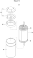
- FIG. 1 is an exploded perspective view of a cylindrical secondary battery in the related art.
- a cylindrical secondary battery 10 may be manufactured by accommodating a jelly-roll electrode assembly 20 in a cylindrical battery casing 30, injecting an electrolyte into the battery casing 30, and then coupling a cap assembly 70 to an upper end of the battery casing 30.
- the cap assembly 70 may include an upper end cap 71 configured to define a positive electrode terminal, and a cap plate 72 configured to be in close contact with the upper end cap 71.
- the cap assembly 70 and the battery casing 30 are coupled by crimping coupling, such that the secondary battery 10 may be sealed.
- a gasket 80 may be positioned between the cap assembly 70 and the battery casing 30 in order to improve sealability.
- an electrode current collector of an electrode sheet included in the electrode assembly 20 may be exposed to an outer peripheral surface of the electrode assembly 20.
- the exposed electrode current collector is brought into contact with an inner wall of the battery casing 30, such that it is possible to ensure an electron movement route in addition to an electrode tab and reduce resistance of the secondary battery.
- the electrode current collector is in direct contact with the inner wall of the battery casing 30, such that the heat dissipation performance is improved.
- a sealing tape 50 is generally attached to an outer peripheral surface of the jelly-roll electrode assembly in order to prevent the jelly-roll electrode assembly from being unwound.
- the sealing tape 50 is attached only to a part of the outer peripheral surface of the electrode assembly 20 without being attached to the entire outer peripheral surface of the electrode assembly 20 in order to guide the contact between the electrode current collector and the battery casing 30.
- the presence of the sealing tape 50 acts as a factor that hinders the reduction in resistance and the improvement of the heat dissipation performance.
- the present invention has been made in an effort to provide a method of manufacturing a secondary battery, which is capable of increasing a contact area between an electrode current collector and an inner wall of the battery casing.
- An exemplary embodiment of the present invention provides a method of manufacturing a secondary battery, the method including: manufacturing a jelly-roll electrode assembly by winding a first electrode, a second electrode, and a separator together; attaching a tape to cover an outermost edge portion of the electrode assembly; accommodating the electrode assembly in a battery casing opened at an upper side thereof; and removing the tape attached to the electrode assembly from the electrode assembly.
- the tape may include a first portion attached to the electrode assembly, and a second portion extending in an upward direction of the electrode assembly from the first portion. In the removing of the tape, the tape may be removed by pulling the second portion.
- the tape may extend in a height direction of the electrode assembly and cover the outermost edge portion of the electrode assembly.
- the first electrode may include a first electrode current collector, and a first active material layer formed by applying an electrode active material onto the first electrode current collector, and the first electrode current collector may include an exposed portion exposed to an outer peripheral surface of the electrode assembly.
- the electrode assembly may be unwound in the battery casing, and the exposed portion may be in contact with an inner wall of the battery casing.
- the second portion of the tape may extend in the upward direction from the electrode assembly and be exposed.
- the second portion may be a portion having no adhesiveness.
- the second portion may be in a state in which the second portion is folded so that portions having adhesiveness face each other.
- the tape may include a bending portion that is a portion curved between the first portion and the second portion.
- the bending portion may be formed at lower sides of the first and second portions.
- the tape may be removed by pulling the second portion in the upward direction.
- a portion of the first portion, which has adhesiveness, may be positioned at a side directed toward the electrode assembly, and a portion of the second portion, which has adhesiveness, may be positioned at a side opposite to the electrode assembly.
- the battery casing may be a cylindrical casing.
- the structure in which the tape attached to the outer peripheral surface of the electrode assembly may be easily removed is provided. Further, the tape is removed in the state in which the electrode assembly is accommodated in the battery casing. Therefore, it is possible to maximize the contact area between the inner wall of the battery casing and the electrode current collector exposed to the outer peripheral surface of the electrode assembly.
- one component such as a layer, a film, a region, or a plate
- one component can be positioned “directly on” another component, and one component can also be positioned on another component with other components interposed therebetween.
- one component is described as being positioned “directly on” another component, there is no component therebetween.
- the component may be positioned “above” or “below” the reference part, and this configuration does not necessarily mean that the component is positioned “above” or “on” the reference part in a direction opposite to gravity.
- the word “in a plan view” means when an object is viewed from above, and the word “in a cross-sectional view” means when a cross section made by vertically cutting an object is viewed from a lateral side.
- FIG. 2 is an exploded perspective view illustrating a state in which an electrode assembly according to an embodiment of the present invention is disassembled before the electrode assembly is wound.
- FIG. 3 is a perspective view illustrating a state in which the electrode assembly in FIG. 2 is wound.
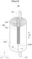
- FIG. 4 is a perspective view illustrating a state in which a tape is attached to an outer peripheral surface of the electrode assembly in FIG. 3 .
- a method of manufacturing a secondary battery includes a step of manufacturing a jelly-roll electrode assembly 200 by winding a first electrode 210, a second electrode 220, and separators 230 and 240 together, and a step of attaching a tape 500 to cover an outermost edge portion 211ED of the electrode assembly 200.
- the jelly-roll electrode assembly 200 may be manufactured by winding the first electrode 210, the second electrode 220, and the separator 230 together.
- the separator 230 may be interposed between the first electrode 210 and the second electrode 220.
- the separator 240 may be additionally disposed under the second electrode 220 in order to prevent the first electrode 210 and the second electrode 220 from adjoining each other when the first electrode 210, the second electrode 220, and the separator 230 are wound in a jelly-roll shape.
- the first electrode 210 may include a first electrode current collector 211, and a first active material layer 212 formed on the first electrode current collector 211 by applying an electrode active material. Specifically, the first active material layer 212 is formed by applying the electrode active material onto the first electrode current collector 211.
- a first electrode tab 213 may be attached, by welding or the like, to a portion of the first electrode current collector 211 that is not coated with the electrode active material such that the first electrode current collector 211 is exposed. In this case, the first electrode tab 213 is illustrated as being positioned at one end of the first electrode 210, but the position of the first electrode tab 213 is not particularly limited. The first electrode tab 213 may be positioned at a central portion of the first electrode 210.
- the second electrode 220 may include a second electrode current collector 221, and a second active material layer 222 formed on the second electrode current collector 221 by applying an electrode active material. Specifically, the second active material layer 222 is formed by applying the electrode active material onto the second electrode current collector 221.
- a second electrode tab 223 may be attached, by welding or the like to a portion of the second electrode current collector 221 that is not coated with the electrode active material such that the second electrode current collector 221 is exposed. In this case, the second electrode tab 223 is illustrated as being positioned at a central portion of the second electrode 220, but the position of the second electrode tab 223 is not particularly limited. The second electrode tab 223 may be positioned at one end of the second electrode 220.
- the first electrode current collector 211 includes an exposed portion 211E exposed to the outer peripheral surface of the electrode assembly 200. That is, the exposed portion 211E may be a portion of the first electrode current collector 211 that is exposed regardless of the attachment of the first electrode tab 213. As illustrated in FIG. 2 , the exposed portion 211E may be positioned at the other end of the first electrode 210 spaced apart from the portion to which the first electrode tab 213 is attached. As illustrated in FIG. 3 , the exposed portion 211E is exposed to the outer peripheral surface of the electrode assembly 200 when the electrode assembly 200 illustrated in FIG. 2 is wound. The tape 500 may be attached to the outer peripheral surface of the electrode assembly 200.
- the tape 500 according to the present embodiment may extend in a height direction d1 of the electrode assembly 200 and cover the outermost edge portion 211ED of the exposed portion 211E.
- FIG. 3 illustrates a state before the tape is attached
- FIG. 4 illustrates a state after the tape is attached.
- the outer peripheral surface of the electrode assembly 200 means an outer curved portion of the wound electrode assembly 200 having a cylindrical shape.
- the height direction d1 of the electrode assembly 200 means directions (z-axis direction and -z-axis direction) in which the electrode tabs 213 and 223 protrude relative to the electrode assembly 200.
- the outermost edge portion 211ED of the exposed portion 211E means one end that is finally wound when the first electrode 210 is wound.
- the first electrode current collector 211 extends toward one side to form the exposed portion 211E, and the exposed portion 211E is further wound to the extent that the first electrode current collector 211 extends. Therefore, the exposed portion 211E may be formed on at least a part of the outer peripheral surface of the electrode assembly 200.
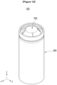
- FIG. 5 is a perspective view illustrating a state in which the electrode assembly in FIG. 4 is accommodated in a battery casing.
- the method of manufacturing a secondary battery according to the present embodiment includes a step of accommodating the electrode assembly 200 in a battery casing 300 opened at an upper side thereof.
- the battery casing 300 is a structure for accommodating the electrode assembly 200 impregnated with the electrolyte.
- the battery casing 300 may be made of a metallic material and be a cylindrical casing.
- the tape 500 covers the outermost edge portion 211ED of the wound jelly-roll electrode assembly 200, it is possible to prevent the wound electrode assembly 200 from being unwound during the manufacturing process of moving the electrode assembly 200 or accommodating the electrode assembly 200 in the battery casing 300. As described above, to prevent the electrode assembly 200 from being unwound, the tape 500 may be continuously formed in the height direction d1 instead of a direction d2 in which the electrode assembly 200 is wound.
- FIG. 6 is a perspective view illustrating a step of removing the tape from the electrode assembly according to the embodiment of the present invention.
- the method of manufacturing a secondary battery according to the present embodiment includes a step of removing the tape 500 attached to the electrode assembly 200 from the electrode assembly 200.
- the tape 500 attached to the outer peripheral surface of the electrode assembly 200 may be removed in the state in which the electrode assembly 200 is accommodated in the battery casing 300.
- the tape 500 may include a first portion 510 attached to the electrode assembly 200, and a second portion 520 extending in an upward direction of the electrode assembly 200 from the first portion 510.
- the tape 500 is removed from the electrode assembly 200 by pulling the second portion 520 of the tape 500. That is, to make it easy to remove the tape 500, the second portion 520 of the tape 500 may extend in the upward direction from the electrode assembly 200 and be exposed.
- the first portion 510 is a portion having adhesiveness and configured to be attached to the outer peripheral surface of the electrode assembly 200
- the second portion 520 according to the present embodiment may be a portion having no adhesiveness.
- the second portion 520 may have no adhesiveness because the second portion 520 need not be attached to other components as well as the electrode assembly 200.
- first portion 510 of the tape 500 may have a somewhat low bonding force so that the tape 500 is easily removed.
- FIG. 7 is a cross-sectional view illustrating a cross-section taken along cutting line A-A' in FIG. 6 .
- FIG. 7 illustrates a state after the tape 500 illustrated in FIG. 6 is removed.
- the electrode assembly 200 when the tape 500 is removed in the step of removing the tape 500, the electrode assembly 200 may be unwound in the battery casing 300, and the exposed portion 211E may come into contact with an inner wall of the battery casing 300. That is, when the tape 500 is pulled so as to be removed, the wound electrode assembly 200 is naturally unwound in the battery casing 300 by a pulling force. Therefore, the exposed portion 211E, which is exposed to the outer peripheral surface of the electrode assembly 200, may be in contact with the inner wall of the battery casing 300. Because the tape 500 is completely removed, the exposed portion 211E may be in contact with the inner wall of the battery casing 300 through a large area.
- the first electrode tab 213 protruding from the electrode assembly 200 may be joined to a bottom of the battery casing 300 and serve as an electrode terminal for connecting the battery casing 300 to an external circuit.
- the contact between the exposed portion 211E and the inner wall of the battery casing 300 may ensure an additional electron movement route in addition to the first electrode tab 213. Because the additional electron movement route is ensured, the resistance of the secondary battery 100 may be reduced. Therefore, the lifespan and efficiency of the secondary battery according to the present embodiment may be improved.
- heat is generated from the electrode assembly 200 of the secondary battery as the secondary battery is repeatedly charged and discharged. Because the exposed portion 211E of the electrode assembly 200 is in direct contact with the battery casing 300, the heat may be easily dissipated to the outside, thereby improving the heat dissipation performance.
- the electrode assembly 20 is accommodated in the battery casing 30 in the state in which the sealing tape 50 is attached to the outer peripheral surface of the electrode assembly 20, and then the battery casing 30 is sealed by the cap assembly 70.
- the sealing tape 50 attached to the outer peripheral surface of the electrode assembly 20 inevitably restricts the contact between the electrode current collector and the battery casing.
- the secondary battery 10 in the related art is inevitably poor in terms of resistance characteristics or heat dissipation performance in comparison with the secondary battery manufactured by removing the tape 500 according to the embodiment of the present invention.
- FIG. 8 is a graph for comparing resistance characteristics between the secondary battery including the electrode assembly according to the embodiment of the present invention and the secondary battery including the electrode assembly in the related art.
- the secondary battery including the electrode assembly to which the two sealing tapes 50 are attached as illustrated in FIG. 1 corresponds to sample A.
- the secondary battery including the electrode assembly from which the tape 500 is removed according to the embodiment of the present invention corresponds to sample E.
- a tape made of polyimide was used as the sealing tape 50 of sample A.
- Resistance of sample A and resistance of sample E were measured by a 1 khz HIOKI AC resistance measurer. Ten samples were provided, and distribution levels were checked.
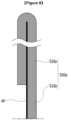
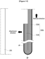
- FIG. 9 is a partial view illustrating an upper portion of a tape according to another embodiment of the present invention.
- a tape 500a according to another embodiment of the present invention may include a first portion 510a attached to the electrode assembly 200, and a second portion 520a extending in the upward direction of the electrode assembly 200 from the first portion 510a.
- the second portion 520a may be in a state in which the second portion 520a is folded so that portions AP having adhesiveness face each other.
- a part of an upper end of the tape 500a having the portions AP each having adhesiveness on only one surface is folded so that the portions AP having adhesiveness face each other, such that the first portion 510a and the second portion 520a may be simply provided.
- the second portion 520a is not attached to the other components as well as the electrode assembly 200. Further, the tape 500a may be removed from the electrode assembly in the battery casing by pulling the second portion 520a.
- FIG. 10 is a perspective view illustrating an electrode assembly and a tape according to a modified embodiment of the present invention.
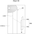
- FIG. 11 is a top plan view illustrating the electrode assembly and the tape in FIG. 10 .
- a tape 500b according to the modified embodiment of the present invention is attached to cover the outermost edge portion 211ED of the jelly-roll electrode assembly 200.
- the electrode assembly 200 is inserted into the battery casing, and then the tape 500b is removed from the electrode assembly 200.
- the tape 500b is similar to the above-mentioned tape 500.
- the tape 500b according to the modified embodiment of the present invention includes a first portion 510b attached to the electrode assembly 200, and a second portion 520b extending in the upward direction of the electrode assembly 200 from the first portion 510b.
- the tape 500b is removed from the electrode assembly 200 by pulling the second portion 520b.
- the tape 500b according to the present embodiment differs from the above-mentioned tapes in that a bending portion BP, which is a curved portion, is provided between the first portion 510b and the second portion 520b.
- the bending portion BP is formed at lower sides of the first and second portions 510b and 520b.
- the bending portion BP which separates the first portion 510b and the second portion 520b, may be formed by bending the tape 500b upward once according to the present embodiment.
- FIG. 10 illustrates that the first portion 510b and the second portion 520b are somewhat spaced apart from each other for the convenience of description. However, as illustrated in FIG. 11 , the first portion 510b and the second portion 520b may be in close contact with each other.
- the portion AP of the first portion 510b which has adhesiveness
- the portion AP of the second portion 520b which has adhesiveness, may be positioned at a side opposite to the electrode assembly 200. That is, the portion AP having adhesiveness may be provided on the outer portion of the tape 500b.
- the tape 500b may be removed by pulling the second portion 520b in the upward direction.
- the tape 500b may be naturally removed from the electrode assembly 200 while being moved upward. That is, according to the present embodiment, the tape 500b has the bending portion BP, such that the tape 500b may be more easily removed.
- the tape 500b may be naturally removed by an upward force.
- FIG. 12 is a perspective view illustrating the secondary battery to which a cap assembly is coupled.
- a cap assembly 700 is coupled to the opened upper side of the battery casing 300 after the tape 500 is removed, such that the battery casing 300 may be sealed, and the secondary battery 100 may be manufactured.
- the battery casing 300 and the cap assembly 700 may be coupled by crimping coupling by bending the upper end of the battery casing 300 in a direction toward the cap assembly 700.
- the terms 'front,' 'rear,' 'left,' 'right,' 'upper,' and 'lower' have been used to indicate the directions. However, these terms may be changed depending on a position of a target object or a position of an observer.
- a battery module may be configured by assembling the plurality of secondary batteries manufactured according to the present embodiment.
- the battery modules may be mounted together with various types of control and protection systems such as a battery management system (BMS), a cooling system, and the like, thereby constituting the battery pack.
- BMS battery management system
- a cooling system and the like
- the secondary battery, the battery module, or the battery pack may be applied to various devices.
- the battery module or the battery pack may be applied to transportation means such as electric bicycles, electric vehicles, hybrid vehicles, and the like, but the present invention is not limited thereto.
- the battery module or the battery pack may be applied to various devices capable of using the secondary battery.
Landscapes
- Chemical & Material Sciences (AREA)
- Chemical Kinetics & Catalysis (AREA)
- Electrochemistry (AREA)
- General Chemical & Material Sciences (AREA)
- Engineering & Computer Science (AREA)
- Manufacturing & Machinery (AREA)
- Secondary Cells (AREA)
- Sealing Battery Cases Or Jackets (AREA)
- Hybrid Cells (AREA)
Abstract
Description
- This application claims priority to and the benefit of
Korean Patent Application No. 10-2021-0008179 filed in the Korean Intellectual Property Office on January 20, 2021 - The present invention relates to a method of manufacturing a secondary battery, and more particularly, to a method of manufacturing a secondary battery including a jelly-roll electrode assembly.
- Recently, there is an increasing demand for portable electronic products such as laptops, video cameras, and mobile phones, and the research and development are being actively conducted on electric vehicles, energy storage batteries, robots, satellites, and the like. Therefore, lots of studies are being conducted on secondary batteries used as driving power sources.
- For example, a nickel cadmium battery, a nickel hydrogen battery, a nickel zinc battery, a lithium secondary battery, and the like are used as the secondary battery. Among these batteries, in comparison with the nickel-based secondary battery, the lithium secondary battery causes almost no memory effect and thus is freely charged and discharged. Further, the lithium secondary battery has a very low self-discharge rate, a high operating voltage, and a high energy density per unit weight, and thus the lithium secondary battery is widely used in a cutting-edge electronic device field.
- Depending on shapes of battery casings, the secondary batteries are classified into a cylindrical battery having an electrode assembly embedded in a cylindrical metal can, an angular battery having an electrode assembly embedded in an angular metal can, and a pouch-type battery having an electrode assembly embedded in a pouch-type casing configured by an aluminum laminated sheet. Among these batteries, the cylindrical battery advantageously has a relatively large capacity and is structurally stable.
- The electrode assembly embedded in the battery casing is a power generating element that is chargeable and dischargeable and has a layered structure including a positive electrode, a separator, and a negative electrode. The electrode assemblies are classified into a jelly-roll electrode assembly, a stack electrode assembly, and a stack/folding electrode assembly. The jelly-roll electrode assembly is made by winding positive and negative electrodes with a separator interposed therebetween, the positive and negative electrodes each being provided in the form of a long sheet onto which an active material is applied. The stack electrode assembly is made by sequentially stacking a plurality of positive electrodes having a predetermined size and a plurality of negative electrodes having a predetermined size with separators interposed therebetween. The stack/folding electrode assembly is a combination of the jelly-roll electrode assembly and the stack electrode assembly. Among these electrode assembly, the jelly-roll electrode assembly is advantageously easy to manufacture and has a high energy density per weight.
-
FIG. 1 is an exploded perspective view of a cylindrical secondary battery in the related art. - Referring to
FIG. 1 , a cylindricalsecondary battery 10 may be manufactured by accommodating a jelly-roll electrode assembly 20 in acylindrical battery casing 30, injecting an electrolyte into thebattery casing 30, and then coupling acap assembly 70 to an upper end of thebattery casing 30. - The
cap assembly 70 may include anupper end cap 71 configured to define a positive electrode terminal, and acap plate 72 configured to be in close contact with theupper end cap 71. Thecap assembly 70 and thebattery casing 30 are coupled by crimping coupling, such that thesecondary battery 10 may be sealed. In this case, agasket 80 may be positioned between thecap assembly 70 and thebattery casing 30 in order to improve sealability. - In this case, an electrode current collector of an electrode sheet included in the
electrode assembly 20 may be exposed to an outer peripheral surface of theelectrode assembly 20. The exposed electrode current collector is brought into contact with an inner wall of thebattery casing 30, such that it is possible to ensure an electron movement route in addition to an electrode tab and reduce resistance of the secondary battery. In addition, the electrode current collector is in direct contact with the inner wall of thebattery casing 30, such that the heat dissipation performance is improved. - However, a
sealing tape 50 is generally attached to an outer peripheral surface of the jelly-roll electrode assembly in order to prevent the jelly-roll electrode assembly from being unwound. Thesealing tape 50 is attached only to a part of the outer peripheral surface of theelectrode assembly 20 without being attached to the entire outer peripheral surface of theelectrode assembly 20 in order to guide the contact between the electrode current collector and thebattery casing 30. However, the presence of thesealing tape 50 acts as a factor that hinders the reduction in resistance and the improvement of the heat dissipation performance. - The present invention has been made in an effort to provide a method of manufacturing a secondary battery, which is capable of increasing a contact area between an electrode current collector and an inner wall of the battery casing.
- However, the object to be achieved by the embodiments of the present invention is not limited to the above-mentioned object but may be variously expanded without departing from the technical spirit of the present invention.
- An exemplary embodiment of the present invention provides a method of manufacturing a secondary battery, the method including: manufacturing a jelly-roll electrode assembly by winding a first electrode, a second electrode, and a separator together; attaching a tape to cover an outermost edge portion of the electrode assembly; accommodating the electrode assembly in a battery casing opened at an upper side thereof; and removing the tape attached to the electrode assembly from the electrode assembly. The tape may include a first portion attached to the electrode assembly, and a second portion extending in an upward direction of the electrode assembly from the first portion. In the removing of the tape, the tape may be removed by pulling the second portion.
- The tape may extend in a height direction of the electrode assembly and cover the outermost edge portion of the electrode assembly.
- The first electrode may include a first electrode current collector, and a first active material layer formed by applying an electrode active material onto the first electrode current collector, and the first electrode current collector may include an exposed portion exposed to an outer peripheral surface of the electrode assembly.
- As the tape is removed in the removing of the tape, the electrode assembly may be unwound in the battery casing, and the exposed portion may be in contact with an inner wall of the battery casing.
- The second portion of the tape may extend in the upward direction from the electrode assembly and be exposed.
- The second portion may be a portion having no adhesiveness.
- The second portion may be in a state in which the second portion is folded so that portions having adhesiveness face each other.
- The tape may include a bending portion that is a portion curved between the first portion and the second portion.
- The bending portion may be formed at lower sides of the first and second portions.
- In the removing of the tape, the tape may be removed by pulling the second portion in the upward direction.
- A portion of the first portion, which has adhesiveness, may be positioned at a side directed toward the electrode assembly, and a portion of the second portion, which has adhesiveness, may be positioned at a side opposite to the electrode assembly.
- The battery casing may be a cylindrical casing.
- According to the embodiments of the present invention, the structure in which the tape attached to the outer peripheral surface of the electrode assembly may be easily removed is provided. Further, the tape is removed in the state in which the electrode assembly is accommodated in the battery casing. Therefore, it is possible to maximize the contact area between the inner wall of the battery casing and the electrode current collector exposed to the outer peripheral surface of the electrode assembly.
- The effects of the present invention are not limited to the aforementioned effects, and other effects, which are not mentioned above, will be clearly understood by those skilled in the art from the claims.
-
-
FIG. 1 is an exploded perspective view of a cylindrical secondary battery in the related art. -
FIG. 2 is an exploded perspective view illustrating a state in which an electrode assembly according to an embodiment of the present invention is disassembled before the electrode assembly is wound. -
FIG. 3 is a perspective view illustrating a state in which the electrode assembly inFIG. 2 is wound. -
FIG. 4 is a perspective view illustrating a state in which a tape is attached to an outer peripheral surface of the electrode assembly inFIG. 3 . -
FIG. 5 is a perspective view illustrating a state in which the electrode assembly inFIG. 4 is accommodated in a battery casing. -
FIG. 6 is a perspective view illustrating a step of removing the tape from the electrode assembly according to the embodiment of the present invention. -
FIG. 7 is a cross-sectional view illustrating a cross-section taken along cutting line A-A' inFIG. 6 . -
FIG. 8 is a graph for comparing resistance characteristics between a secondary battery including the electrode assembly according to the embodiment of the present invention and a secondary battery including an electrode assembly in the related art. -
FIG. 9 is a partial view illustrating an upper portion of a tape according to another embodiment of the present invention. -
FIG. 10 is a perspective view illustrating an electrode assembly and a tape according to a modified embodiment of the present invention. -
FIG. 11 is a top plan view illustrating the electrode assembly and the tape inFIG. 10 . -
FIG. 12 is a perspective view illustrating the secondary battery to which a cap assembly is coupled. - Hereinafter, several exemplary embodiments of the present invention will be described in detail with reference to the accompanying drawings so that those with ordinary skill in the art to which the present invention pertains may easily carry out the exemplary embodiments. The present invention may be implemented in various different ways and is not limited to the embodiments described herein.
- A part irrelevant to the description will be omitted to clearly describe the present invention, and the same or similar constituent elements will be designated by the same reference numerals throughout the specification.
- In addition, a size and a thickness of each constituent element illustrated in the drawings are arbitrarily shown for convenience of description, but the present invention is not limited thereto. In order to clearly describe several layers and regions, thicknesses thereof are enlarged in the drawings. In the drawings, the thicknesses of some layers and regions are exaggerated for convenience of description.
- In addition, when one component such as a layer, a film, a region, or a plate is described as being positioned "above" or "on" another component, one component can be positioned "directly on" another component, and one component can also be positioned on another component with other components interposed therebetween. On the contrary, when one component is described as being positioned "directly on" another component, there is no component therebetween. In addition, when a component is described as being positioned "above" or "on" a reference part, the component may be positioned "above" or "below" the reference part, and this configuration does not necessarily mean that the component is positioned "above" or "on" the reference part in a direction opposite to gravity.
- Throughout the specification, unless explicitly described to the contrary, the word "comprise/include" and variations such as "comprises/includes" or "comprising/including" will be understood to imply the inclusion of stated elements, not the exclusion of any other elements.
- Throughout the specification, the word "in a plan view" means when an object is viewed from above, and the word "in a cross-sectional view" means when a cross section made by vertically cutting an object is viewed from a lateral side.
-
FIG. 2 is an exploded perspective view illustrating a state in which an electrode assembly according to an embodiment of the present invention is disassembled before the electrode assembly is wound.FIG. 3 is a perspective view illustrating a state in which the electrode assembly inFIG. 2 is wound.FIG. 4 is a perspective view illustrating a state in which a tape is attached to an outer peripheral surface of the electrode assembly inFIG. 3 . - Referring to
FIGS. 2 to 4 , a method of manufacturing a secondary battery according to an embodiment of the present invention includes a step of manufacturing a jelly-roll electrode assembly 200 by winding afirst electrode 210, asecond electrode 220, andseparators tape 500 to cover an outermost edge portion 211ED of theelectrode assembly 200. - Specifically, the jelly-
roll electrode assembly 200 may be manufactured by winding thefirst electrode 210, thesecond electrode 220, and theseparator 230 together. Theseparator 230 may be interposed between thefirst electrode 210 and thesecond electrode 220. Further, theseparator 240 may be additionally disposed under thesecond electrode 220 in order to prevent thefirst electrode 210 and thesecond electrode 220 from adjoining each other when thefirst electrode 210, thesecond electrode 220, and theseparator 230 are wound in a jelly-roll shape. - The
first electrode 210 may include a first electrodecurrent collector 211, and a firstactive material layer 212 formed on the first electrodecurrent collector 211 by applying an electrode active material. Specifically, the firstactive material layer 212 is formed by applying the electrode active material onto the first electrodecurrent collector 211. Afirst electrode tab 213 may be attached, by welding or the like, to a portion of the first electrodecurrent collector 211 that is not coated with the electrode active material such that the first electrodecurrent collector 211 is exposed. In this case, thefirst electrode tab 213 is illustrated as being positioned at one end of thefirst electrode 210, but the position of thefirst electrode tab 213 is not particularly limited. Thefirst electrode tab 213 may be positioned at a central portion of thefirst electrode 210. - The
second electrode 220 may include a second electrodecurrent collector 221, and a secondactive material layer 222 formed on the second electrodecurrent collector 221 by applying an electrode active material. Specifically, the secondactive material layer 222 is formed by applying the electrode active material onto the second electrodecurrent collector 221. Asecond electrode tab 223 may be attached, by welding or the like to a portion of the second electrodecurrent collector 221 that is not coated with the electrode active material such that the second electrodecurrent collector 221 is exposed. In this case, thesecond electrode tab 223 is illustrated as being positioned at a central portion of thesecond electrode 220, but the position of thesecond electrode tab 223 is not particularly limited. Thesecond electrode tab 223 may be positioned at one end of thesecond electrode 220. - Meanwhile, the first electrode
current collector 211 includes an exposedportion 211E exposed to the outer peripheral surface of theelectrode assembly 200. That is, the exposedportion 211E may be a portion of the first electrodecurrent collector 211 that is exposed regardless of the attachment of thefirst electrode tab 213. As illustrated inFIG. 2 , the exposedportion 211E may be positioned at the other end of thefirst electrode 210 spaced apart from the portion to which thefirst electrode tab 213 is attached. As illustrated inFIG. 3 , the exposedportion 211E is exposed to the outer peripheral surface of theelectrode assembly 200 when theelectrode assembly 200 illustrated inFIG. 2 is wound. Thetape 500 may be attached to the outer peripheral surface of theelectrode assembly 200. Thetape 500 according to the present embodiment may extend in a height direction d1 of theelectrode assembly 200 and cover the outermost edge portion 211ED of the exposedportion 211E. For the convenience of description,FIG. 3 illustrates a state before the tape is attached, andFIG. 4 illustrates a state after the tape is attached. - In this case, the outer peripheral surface of the
electrode assembly 200 means an outer curved portion of thewound electrode assembly 200 having a cylindrical shape. The height direction d1 of theelectrode assembly 200 means directions (z-axis direction and -z-axis direction) in which theelectrode tabs electrode assembly 200. The outermost edge portion 211ED of the exposedportion 211E means one end that is finally wound when thefirst electrode 210 is wound. - The first electrode
current collector 211 extends toward one side to form the exposedportion 211E, and the exposedportion 211E is further wound to the extent that the first electrodecurrent collector 211 extends. Therefore, the exposedportion 211E may be formed on at least a part of the outer peripheral surface of theelectrode assembly 200. -
FIG. 5 is a perspective view illustrating a state in which the electrode assembly inFIG. 4 is accommodated in a battery casing. - Referring to
FIGS. 4 and5 , the method of manufacturing a secondary battery according to the present embodiment includes a step of accommodating theelectrode assembly 200 in abattery casing 300 opened at an upper side thereof. Thebattery casing 300 is a structure for accommodating theelectrode assembly 200 impregnated with the electrolyte. Thebattery casing 300 may be made of a metallic material and be a cylindrical casing. - Because the
tape 500 covers the outermost edge portion 211ED of the wound jelly-roll electrode assembly 200, it is possible to prevent thewound electrode assembly 200 from being unwound during the manufacturing process of moving theelectrode assembly 200 or accommodating theelectrode assembly 200 in thebattery casing 300. As described above, to prevent theelectrode assembly 200 from being unwound, thetape 500 may be continuously formed in the height direction d1 instead of a direction d2 in which theelectrode assembly 200 is wound. -
FIG. 6 is a perspective view illustrating a step of removing the tape from the electrode assembly according to the embodiment of the present invention. - Referring to
FIGS. 4 to 6 , the method of manufacturing a secondary battery according to the present embodiment includes a step of removing thetape 500 attached to theelectrode assembly 200 from theelectrode assembly 200. Specifically, thetape 500 attached to the outer peripheral surface of theelectrode assembly 200 may be removed in the state in which theelectrode assembly 200 is accommodated in thebattery casing 300. - In this case, as illustrated in
FIG. 4 , thetape 500 according to the present embodiment may include afirst portion 510 attached to theelectrode assembly 200, and asecond portion 520 extending in an upward direction of theelectrode assembly 200 from thefirst portion 510. - In the step of removing the
tape 500, thetape 500 is removed from theelectrode assembly 200 by pulling thesecond portion 520 of thetape 500. That is, to make it easy to remove thetape 500, thesecond portion 520 of thetape 500 may extend in the upward direction from theelectrode assembly 200 and be exposed. In addition, thefirst portion 510 is a portion having adhesiveness and configured to be attached to the outer peripheral surface of theelectrode assembly 200, whereas thesecond portion 520 according to the present embodiment may be a portion having no adhesiveness. For the convenience of processes, thesecond portion 520 may have no adhesiveness because thesecond portion 520 need not be attached to other components as well as theelectrode assembly 200. - In addition, the
first portion 510 of thetape 500 may have a somewhat low bonding force so that thetape 500 is easily removed. -
FIG. 7 is a cross-sectional view illustrating a cross-section taken along cutting line A-A' inFIG. 6 . In this case,FIG. 7 illustrates a state after thetape 500 illustrated inFIG. 6 is removed. - Referring to
FIGS. 3 ,4 ,6 , and7 , when thetape 500 is removed in the step of removing thetape 500, theelectrode assembly 200 may be unwound in thebattery casing 300, and the exposedportion 211E may come into contact with an inner wall of thebattery casing 300. That is, when thetape 500 is pulled so as to be removed, thewound electrode assembly 200 is naturally unwound in thebattery casing 300 by a pulling force. Therefore, the exposedportion 211E, which is exposed to the outer peripheral surface of theelectrode assembly 200, may be in contact with the inner wall of thebattery casing 300. Because thetape 500 is completely removed, the exposedportion 211E may be in contact with the inner wall of thebattery casing 300 through a large area. - Specifically, although not illustrated, the
first electrode tab 213 protruding from theelectrode assembly 200 may be joined to a bottom of thebattery casing 300 and serve as an electrode terminal for connecting thebattery casing 300 to an external circuit. In this case, the contact between the exposedportion 211E and the inner wall of thebattery casing 300 may ensure an additional electron movement route in addition to thefirst electrode tab 213. Because the additional electron movement route is ensured, the resistance of thesecondary battery 100 may be reduced. Therefore, the lifespan and efficiency of the secondary battery according to the present embodiment may be improved. - In addition, heat is generated from the
electrode assembly 200 of the secondary battery as the secondary battery is repeatedly charged and discharged. Because the exposedportion 211E of theelectrode assembly 200 is in direct contact with thebattery casing 300, the heat may be easily dissipated to the outside, thereby improving the heat dissipation performance. - In the case of the
secondary battery 10 in the related art illustrated inFIG. 1 , theelectrode assembly 20 is accommodated in thebattery casing 30 in the state in which the sealingtape 50 is attached to the outer peripheral surface of theelectrode assembly 20, and then thebattery casing 30 is sealed by thecap assembly 70. Even though the electrode current collector is exposed to the outer peripheral surface of theelectrode assembly 20, the sealingtape 50 attached to the outer peripheral surface of theelectrode assembly 20 inevitably restricts the contact between the electrode current collector and the battery casing. For this reason, thesecondary battery 10 in the related art is inevitably poor in terms of resistance characteristics or heat dissipation performance in comparison with the secondary battery manufactured by removing thetape 500 according to the embodiment of the present invention. -
FIG. 8 is a graph for comparing resistance characteristics between the secondary battery including the electrode assembly according to the embodiment of the present invention and the secondary battery including the electrode assembly in the related art. - Referring to
FIG. 8 , the secondary battery including the electrode assembly to which the two sealingtapes 50 are attached as illustrated inFIG. 1 corresponds to sample A. The secondary battery including the electrode assembly from which thetape 500 is removed according to the embodiment of the present invention corresponds to sample E. In this case, a tape made of polyimide was used as the sealingtape 50 of sample A. - Resistance of sample A and resistance of sample E were measured by a 1 khz HIOKI AC resistance measurer. Ten samples were provided, and distribution levels were checked.
- It can be seen from the result of measuring the resistance characteristics that the resistance characteristics of the secondary battery from which the tape removed according to the present embodiment are improved by about 1m ohm in comparison with the secondary battery in the related art to which the sealing tape is attached.
-
FIG. 9 is a partial view illustrating an upper portion of a tape according to another embodiment of the present invention. - As described above, the
second portion 520 of thetape 500 according to the embodiment of the present invention may have no adhesiveness. Atape 500a according to another embodiment of the present invention may include afirst portion 510a attached to theelectrode assembly 200, and asecond portion 520a extending in the upward direction of theelectrode assembly 200 from thefirst portion 510a. In this case, thesecond portion 520a may be in a state in which thesecond portion 520a is folded so that portions AP having adhesiveness face each other. A part of an upper end of thetape 500a having the portions AP each having adhesiveness on only one surface is folded so that the portions AP having adhesiveness face each other, such that thefirst portion 510a and thesecond portion 520a may be simply provided. - Therefore, the
second portion 520a is not attached to the other components as well as theelectrode assembly 200. Further, thetape 500a may be removed from the electrode assembly in the battery casing by pulling thesecond portion 520a. - Hereinafter, a tape according to a modified embodiment of the present invention will be described with reference to
FIGS. 10 and11 . -
FIG. 10 is a perspective view illustrating an electrode assembly and a tape according to a modified embodiment of the present invention.FIG. 11 is a top plan view illustrating the electrode assembly and the tape inFIG. 10 . - Referring to
FIGS. 10 and11 , atape 500b according to the modified embodiment of the present invention is attached to cover the outermost edge portion 211ED of the jelly-roll electrode assembly 200. Theelectrode assembly 200 is inserted into the battery casing, and then thetape 500b is removed from theelectrode assembly 200. In this point, thetape 500b is similar to the above-mentionedtape 500. - The
tape 500b according to the modified embodiment of the present invention includes afirst portion 510b attached to theelectrode assembly 200, and asecond portion 520b extending in the upward direction of theelectrode assembly 200 from thefirst portion 510b. Thetape 500b is removed from theelectrode assembly 200 by pulling thesecond portion 520b. - However, the
tape 500b according to the present embodiment differs from the above-mentioned tapes in that a bending portion BP, which is a curved portion, is provided between thefirst portion 510b and thesecond portion 520b. The bending portion BP is formed at lower sides of the first andsecond portions first portion 510b and thesecond portion 520b, may be formed by bending thetape 500b upward once according to the present embodiment.FIG. 10 illustrates that thefirst portion 510b and thesecond portion 520b are somewhat spaced apart from each other for the convenience of description. However, as illustrated inFIG. 11 , thefirst portion 510b and thesecond portion 520b may be in close contact with each other. - In this case, as illustrated in
FIG. 11 , the portion AP of thefirst portion 510b, which has adhesiveness, may be positioned at a side directed toward theelectrode assembly 200. The portion AP of thesecond portion 520b, which has adhesiveness, may be positioned at a side opposite to theelectrode assembly 200. That is, the portion AP having adhesiveness may be provided on the outer portion of thetape 500b. - In a step of removing the
tape 500b according to the present embodiment, thetape 500b may be removed by pulling thesecond portion 520b in the upward direction. As thesecond portion 520b is pulled in the upward direction, thetape 500b may be naturally removed from theelectrode assembly 200 while being moved upward. That is, according to the present embodiment, thetape 500b has the bending portion BP, such that thetape 500b may be more easily removed. In particular, there is a process advantage in that in the limited space in the battery casing, thetape 500b may be naturally removed by an upward force. -
FIG. 12 is a perspective view illustrating the secondary battery to which a cap assembly is coupled. - Referring to
FIGS. 6 and12 , acap assembly 700 is coupled to the opened upper side of thebattery casing 300 after thetape 500 is removed, such that thebattery casing 300 may be sealed, and thesecondary battery 100 may be manufactured. - The
battery casing 300 and thecap assembly 700 may be coupled by crimping coupling by bending the upper end of thebattery casing 300 in a direction toward thecap assembly 700. - In the present embodiment, the terms 'front,' 'rear,' 'left,' 'right,' 'upper,' and 'lower' have been used to indicate the directions. However, these terms may be changed depending on a position of a target object or a position of an observer.
- A battery module may be configured by assembling the plurality of secondary batteries manufactured according to the present embodiment. The battery modules may be mounted together with various types of control and protection systems such as a battery management system (BMS), a cooling system, and the like, thereby constituting the battery pack.
- The secondary battery, the battery module, or the battery pack may be applied to various devices. Specifically, the battery module or the battery pack may be applied to transportation means such as electric bicycles, electric vehicles, hybrid vehicles, and the like, but the present invention is not limited thereto. The battery module or the battery pack may be applied to various devices capable of using the secondary battery.
- Although preferred examples of the present invention have been described in detail hereinabove, the right scope of the present invention is not limited thereto, and many variations and modifications of those skilled in the art using the basic concept of the present invention, which is defined in the following claims, will also belong to the right scope of the present invention.
-
- 200: Electrode assembly
- 211E: Exposed portion
- 211ED: Outermost edge portion
- 500, 500a, 500b: Tape
Claims (12)
- A method of manufacturing a secondary battery, the method comprising:manufacturing a jelly-roll electrode assembly by winding a first electrode, a second electrode, and a separator together;attaching a tape to cover an outermost edge portion of the electrode assembly;accommodating the electrode assembly in a battery casing opened at an upper side thereof; andremoving the tape attached to the electrode assembly from the electrode assembly,wherein the tape comprises a first portion attached to the electrode assembly, and a second portion extending in an upward direction of the electrode assembly from the first portion, andwherein in the removing of the tape, the tape is removed by pulling the second portion.
- The method of claim 1, wherein:
the tape extends in a height direction of the electrode assembly and covers the outermost edge portion of the electrode assembly. - The method of claim 1, wherein:the first electrode comprises a first electrode current collector, and a first active material layer formed by applying an electrode active material onto the first electrode current collector, andthe first electrode current collector comprises an exposed portion exposed to an outer peripheral surface of the electrode assembly.
- The method of claim 3, wherein:
as the tape is removed in the removing of the tape, the electrode assembly is unwound in the battery casing, and the exposed portion is in contact with an inner wall of the battery casing. - The method of claim 1, wherein:
the second portion of the tape extends in the upward direction from the electrode assembly and is exposed. - The method of claim 1, wherein:
the second portion is a portion having no adhesiveness. - The method of claim 1, wherein:
the second portion is in a state in which the second portion is folded so that portions having adhesiveness face each other. - The method of claim 1, wherein:
the tape comprises a bending portion that is a portion curved between the first portion and the second portion. - The method of claim 8, wherein:
the bending portion is formed at lower sides of the first and second portions. - The method of claim 9, wherein:
in the removing of the tape, the tape is removed by pulling the second portion in the upward direction. - The method of claim 8, wherein:a portion of the first portion, which has adhesiveness, is positioned at a side directed toward the electrode assembly, anda portion of the second portion, which has adhesiveness, is positioned at a side opposite to the electrode assembly.
- The method of claim 1, wherein:
the battery casing is a cylindrical casing.
Applications Claiming Priority (2)
| Application Number | Priority Date | Filing Date | Title |
|---|---|---|---|
| KR1020210008179A KR102754514B1 (en) | 2021-01-20 | 2021-01-20 | Manufacturing method of secondary battery |
| PCT/KR2022/000994 WO2022158853A1 (en) | 2021-01-20 | 2022-01-19 | Manufacturing method of secondary battery |
Publications (3)
| Publication Number | Publication Date |
|---|---|
| EP4181255A1 true EP4181255A1 (en) | 2023-05-17 |
| EP4181255A4 EP4181255A4 (en) | 2025-01-08 |
| EP4181255B1 EP4181255B1 (en) | 2025-12-03 |
Family
ID=82548862
Family Applications (1)
| Application Number | Title | Priority Date | Filing Date |
|---|---|---|---|
| EP22742829.9A Active EP4181255B1 (en) | 2021-01-20 | 2022-01-19 | Method of manufacturing secondary battery |
Country Status (7)
| Country | Link |
|---|---|
| US (1) | US12597629B2 (en) |
| EP (1) | EP4181255B1 (en) |
| JP (1) | JP7428308B2 (en) |
| KR (1) | KR102754514B1 (en) |
| CN (1) | CN115917813A (en) |
| ES (1) | ES3064248T3 (en) |
| WO (1) | WO2022158853A1 (en) |
Families Citing this family (1)
| Publication number | Priority date | Publication date | Assignee | Title |
|---|---|---|---|---|
| KR20250101458A (en) * | 2023-12-27 | 2025-07-04 | 주식회사 엘지에너지솔루션 | Electrode assembly, and battery and battery pack comprising the same |
Family Cites Families (22)
| Publication number | Priority date | Publication date | Assignee | Title |
|---|---|---|---|---|
| US5184997A (en) * | 1986-06-20 | 1993-02-09 | Curwood, Inc. | Easy-open case taping method and apparatus |
| US4802275A (en) | 1987-03-12 | 1989-02-07 | Saft, S.A. | Method of manufacturing an electrochemical cell having an alkaline electrolyte and spiral-wound electrodes |
| US4929519A (en) * | 1989-07-20 | 1990-05-29 | Gates Energy Products, Inc. | Wound electrode assembly for an electrochemical cell |
| JP2860350B2 (en) * | 1991-04-30 | 1999-02-24 | コニカ株式会社 | Tape peeling method for roll-shaped sheet and its peeling device |
| JPH11273743A (en) * | 1998-03-24 | 1999-10-08 | Sony Corp | Cylindrical non-aqueous electrolyte secondary battery |
| JP2001196090A (en) | 2000-01-12 | 2001-07-19 | Matsushita Electric Ind Co Ltd | Alkaline storage battery |
| JP2003187874A (en) * | 2001-12-14 | 2003-07-04 | Matsushita Electric Ind Co Ltd | Flat battery |
| KR20040042375A (en) * | 2002-11-14 | 2004-05-20 | 삼성에스디아이 주식회사 | Jelly-roll electrode assembly and secondary battery therewith |
| US7078082B2 (en) * | 2004-01-15 | 2006-07-18 | Sonoco Development, Inc. | Dual-functioning mechanism for startup during winding of web material and for splicing during unwinding |
| JP2006302801A (en) | 2005-04-25 | 2006-11-02 | Matsushita Electric Ind Co Ltd | Winding type secondary battery |
| KR100686813B1 (en) | 2005-04-26 | 2007-02-26 | 삼성에스디아이 주식회사 | Secondary battery |
| KR101152651B1 (en) | 2007-09-12 | 2012-06-04 | 주식회사 엘지화학 | Secondary Battery of Improved Stability by Both Sides Adhesive Tape |
| US8288036B2 (en) * | 2009-05-18 | 2012-10-16 | Samsung Sdi Co., Ltd. | Secondary battery and method of making the secondary battery |
| JP2011034859A (en) | 2009-08-04 | 2011-02-17 | Hitachi Maxell Ltd | Wound electrode body for battery, battery, and its manufacturing method |
| WO2012046911A1 (en) | 2010-10-04 | 2012-04-12 | 주식회사 엘지화학 | Seal tape and secondary battery using same |
| KR101877568B1 (en) | 2012-02-03 | 2018-07-11 | 삼성에스디아이 주식회사 | Pouch type battery |
| JP5900150B2 (en) | 2012-05-21 | 2016-04-06 | 株式会社デンソー | Start control device for in-cylinder internal combustion engine |
| KR20160021514A (en) | 2014-08-18 | 2016-02-26 | 주식회사 엘지화학 | Jelly-Roll Type Electrode Assembly of Improved Stability and Battery Cell Comprising the Same |
| JP6245142B2 (en) | 2014-10-30 | 2017-12-13 | トヨタ自動車株式会社 | Secondary battery manufacturing method and secondary battery |
| KR101835215B1 (en) | 2015-05-22 | 2018-03-06 | 주식회사 엘지화학 | Cylinderical Secondary Battery And Method For Manufacturing The Same |
| JP7211246B2 (en) | 2019-04-22 | 2023-01-24 | トヨタ自動車株式会社 | BATTERY MANUFACTURING METHOD AND BATTERY |
| KR20220021780A (en) * | 2020-08-14 | 2022-02-22 | 주식회사 엘지에너지솔루션 | Rechargeable battery and rechargeable battery manufacturing method |
-
2021
- 2021-01-20 KR KR1020210008179A patent/KR102754514B1/en active Active
-
2022
- 2022-01-19 ES ES22742829T patent/ES3064248T3/en active Active
- 2022-01-19 EP EP22742829.9A patent/EP4181255B1/en active Active
- 2022-01-19 WO PCT/KR2022/000994 patent/WO2022158853A1/en not_active Ceased
- 2022-01-19 US US18/022,909 patent/US12597629B2/en active Active
- 2022-01-19 JP JP2023504685A patent/JP7428308B2/en active Active
- 2022-01-19 CN CN202280005761.9A patent/CN115917813A/en active Pending
Also Published As
| Publication number | Publication date |
|---|---|
| EP4181255A4 (en) | 2025-01-08 |
| CN115917813A (en) | 2023-04-04 |
| KR102754514B1 (en) | 2025-01-13 |
| US12597629B2 (en) | 2026-04-07 |
| KR20220105459A (en) | 2022-07-27 |
| US20230318013A1 (en) | 2023-10-05 |
| JP2023536429A (en) | 2023-08-25 |
| ES3064248T3 (en) | 2026-04-23 |
| JP7428308B2 (en) | 2024-02-06 |
| WO2022158853A1 (en) | 2022-07-28 |
| EP4181255B1 (en) | 2025-12-03 |
Similar Documents
| Publication | Publication Date | Title |
|---|---|---|
| CN103098256B (en) | Pouch case and battery pack including same | |
| US8986871B2 (en) | Electrode assembly and secondary battery having the same | |
| EP3709392A1 (en) | Secondary battery | |
| EP2216841B1 (en) | Pouch-type lithium secondary battery | |
| EP4213295A1 (en) | Secondary battery | |
| KR101915325B1 (en) | Secondary Battery | |
| US20230411811A1 (en) | Secondary battery and device including the same | |
| KR20160032590A (en) | Case assembly, Prismatic secondary battery, and the fabrication method thereof | |
| US20240313331A1 (en) | Connection Wire and Battery Pack Including the Same | |
| KR20220030627A (en) | Secondary battery and device including the same | |
| EP4181255B1 (en) | Method of manufacturing secondary battery | |
| US20170288182A1 (en) | Secondary battery | |
| JP7764637B2 (en) | Prismatic secondary battery | |
| EP4213277A1 (en) | Secondary battery and method of manufacturing the same | |
| KR100580767B1 (en) | Pouch Type Lithium-ion Polymer Battery | |
| KR20040107868A (en) | Pouched-type lithium secondary battery | |
| KR101792578B1 (en) | Battery Cell Having modified Lead Film | |
| KR20140013132A (en) | Secondary battery | |
| US20170069902A1 (en) | Secondary battery | |
| KR20180035510A (en) | Electrode assembly and rechargeable battery including the same | |
| EP4601077A1 (en) | Battery cell and battery device having the same | |
| EP4657614A1 (en) | Battery, battery manufacturing method and automated plant | |
| KR20240012307A (en) | Battery cell unit and battery cell assembly including the same | |
| KR20230133570A (en) | Secondary battery and battery module including the same | |
| KR101211217B1 (en) | Pouch type secondary battery capable of preventing short between electrode lead |
Legal Events
| Date | Code | Title | Description |
|---|---|---|---|
| STAA | Information on the status of an ep patent application or granted ep patent |
Free format text: STATUS: THE INTERNATIONAL PUBLICATION HAS BEEN MADE |
|
| PUAI | Public reference made under article 153(3) epc to a published international application that has entered the european phase |
Free format text: ORIGINAL CODE: 0009012 |
|
| STAA | Information on the status of an ep patent application or granted ep patent |
Free format text: STATUS: REQUEST FOR EXAMINATION WAS MADE |
|
| 17P | Request for examination filed |
Effective date: 20230208 |
|
| AK | Designated contracting states |
Kind code of ref document: A1 Designated state(s): AL AT BE BG CH CY CZ DE DK EE ES FI FR GB GR HR HU IE IS IT LI LT LU LV MC MK MT NL NO PL PT RO RS SE SI SK SM TR |
|
| DAV | Request for validation of the european patent (deleted) | ||
| DAX | Request for extension of the european patent (deleted) | ||
| REG | Reference to a national code |
Ref country code: DE Ref legal event code: R079 Free format text: PREVIOUS MAIN CLASS: H01M0010040000 Ipc: H01M0010052000 Ref document number: 602022026144 Country of ref document: DE |
|
| A4 | Supplementary search report drawn up and despatched |
Effective date: 20241209 |
|
| RIC1 | Information provided on ipc code assigned before grant |
Ipc: H01M 50/107 20210101ALI20241203BHEP Ipc: H01M 10/0587 20100101ALI20241203BHEP Ipc: H01M 50/166 20210101ALI20241203BHEP Ipc: H01M 10/04 20060101ALI20241203BHEP Ipc: H01M 10/052 20100101AFI20241203BHEP |
|
| GRAP | Despatch of communication of intention to grant a patent |
Free format text: ORIGINAL CODE: EPIDOSNIGR1 |
|
| STAA | Information on the status of an ep patent application or granted ep patent |
Free format text: STATUS: GRANT OF PATENT IS INTENDED |
|
| INTG | Intention to grant announced |
Effective date: 20250904 |
|
| GRAS | Grant fee paid |
Free format text: ORIGINAL CODE: EPIDOSNIGR3 |
|
| GRAA | (expected) grant |
Free format text: ORIGINAL CODE: 0009210 |
|
| STAA | Information on the status of an ep patent application or granted ep patent |
Free format text: STATUS: THE PATENT HAS BEEN GRANTED |
|
| AK | Designated contracting states |
Kind code of ref document: B1 Designated state(s): AL AT BE BG CH CY CZ DE DK EE ES FI FR GB GR HR HU IE IS IT LI LT LU LV MC MK MT NL NO PL PT RO RS SE SI SK SM TR |
|
| P01 | Opt-out of the competence of the unified patent court (upc) registered |
Free format text: CASE NUMBER: UPC_APP_0011104_4181255/2025 Effective date: 20251027 |
|
| REG | Reference to a national code |
Ref country code: CH Ref legal event code: F10 Free format text: ST27 STATUS EVENT CODE: U-0-0-F10-F00 (AS PROVIDED BY THE NATIONAL OFFICE) Effective date: 20251203 Ref country code: GB Ref legal event code: FG4D |
|
| REG | Reference to a national code |
Ref country code: DE Ref legal event code: R096 Ref document number: 602022026144 Country of ref document: DE |
|
| REG | Reference to a national code |
Ref country code: IE Ref legal event code: FG4D |
|
| PGFP | Annual fee paid to national office [announced via postgrant information from national office to epo] |
Ref country code: GB Payment date: 20251222 Year of fee payment: 5 |
|
| PGFP | Annual fee paid to national office [announced via postgrant information from national office to epo] |
Ref country code: FR Payment date: 20251223 Year of fee payment: 5 |
|
| PGFP | Annual fee paid to national office [announced via postgrant information from national office to epo] |
Ref country code: BE Payment date: 20251229 Year of fee payment: 5 |
|
| PGFP | Annual fee paid to national office [announced via postgrant information from national office to epo] |
Ref country code: SE Payment date: 20251223 Year of fee payment: 5 |
|
| REG | Reference to a national code |
Ref country code: NL Ref legal event code: MP Effective date: 20251203 |
|
| PGFP | Annual fee paid to national office [announced via postgrant information from national office to epo] |
Ref country code: ES Payment date: 20260211 Year of fee payment: 5 |
|
| REG | Reference to a national code |
Ref country code: LT Ref legal event code: MG9D |
|
| PG25 | Lapsed in a contracting state [announced via postgrant information from national office to epo] |
Ref country code: NO Free format text: LAPSE BECAUSE OF FAILURE TO SUBMIT A TRANSLATION OF THE DESCRIPTION OR TO PAY THE FEE WITHIN THE PRESCRIBED TIME-LIMIT Effective date: 20260303 |
|
| PGFP | Annual fee paid to national office [announced via postgrant information from national office to epo] |
Ref country code: DE Payment date: 20251222 Year of fee payment: 5 |
|
| PG25 | Lapsed in a contracting state [announced via postgrant information from national office to epo] |
Ref country code: FI Free format text: LAPSE BECAUSE OF FAILURE TO SUBMIT A TRANSLATION OF THE DESCRIPTION OR TO PAY THE FEE WITHIN THE PRESCRIBED TIME-LIMIT Effective date: 20251203 Ref country code: HR Free format text: LAPSE BECAUSE OF FAILURE TO SUBMIT A TRANSLATION OF THE DESCRIPTION OR TO PAY THE FEE WITHIN THE PRESCRIBED TIME-LIMIT Effective date: 20251203 |
|
| PGFP | Annual fee paid to national office [announced via postgrant information from national office to epo] |
Ref country code: AT Payment date: 20260301 Year of fee payment: 5 |
|
| PGFP | Annual fee paid to national office [announced via postgrant information from national office to epo] |
Ref country code: HU Payment date: 20260227 Year of fee payment: 5 |
|
| PG25 | Lapsed in a contracting state [announced via postgrant information from national office to epo] |
Ref country code: RS Free format text: LAPSE BECAUSE OF FAILURE TO SUBMIT A TRANSLATION OF THE DESCRIPTION OR TO PAY THE FEE WITHIN THE PRESCRIBED TIME-LIMIT Effective date: 20260303 |
|
| REG | Reference to a national code |
Ref country code: ES Ref legal event code: FG2A Ref document number: 3064248 Country of ref document: ES Kind code of ref document: T3 Effective date: 20260423 |
|
| PG25 | Lapsed in a contracting state [announced via postgrant information from national office to epo] |
Ref country code: LV Free format text: LAPSE BECAUSE OF FAILURE TO SUBMIT A TRANSLATION OF THE DESCRIPTION OR TO PAY THE FEE WITHIN THE PRESCRIBED TIME-LIMIT Effective date: 20251203 |
|
| PG25 | Lapsed in a contracting state [announced via postgrant information from national office to epo] |
Ref country code: BG Free format text: LAPSE BECAUSE OF FAILURE TO SUBMIT A TRANSLATION OF THE DESCRIPTION OR TO PAY THE FEE WITHIN THE PRESCRIBED TIME-LIMIT Effective date: 20251203 |