EP4181085A1 - Method and system for training a neural network to classify objects or events - Google Patents
Method and system for training a neural network to classify objects or events Download PDFInfo
- Publication number
- EP4181085A1 EP4181085A1 EP22213941.2A EP22213941A EP4181085A1 EP 4181085 A1 EP4181085 A1 EP 4181085A1 EP 22213941 A EP22213941 A EP 22213941A EP 4181085 A1 EP4181085 A1 EP 4181085A1
- Authority
- EP
- European Patent Office
- Prior art keywords
- classifier
- sensor
- data
- image data
- apprentice
- Prior art date
- Legal status (The legal status is an assumption and is not a legal conclusion. Google has not performed a legal analysis and makes no representation as to the accuracy of the status listed.)
- Granted
Links
Images


Classifications
-
- G—PHYSICS
- G06—COMPUTING OR CALCULATING; COUNTING
- G06V—IMAGE OR VIDEO RECOGNITION OR UNDERSTANDING
- G06V40/00—Recognition of biometric, human-related or animal-related patterns in image or video data
- G06V40/10—Human or animal bodies, e.g. vehicle occupants or pedestrians; Body parts, e.g. hands
-
- G—PHYSICS
- G06—COMPUTING OR CALCULATING; COUNTING
- G06V—IMAGE OR VIDEO RECOGNITION OR UNDERSTANDING
- G06V10/00—Arrangements for image or video recognition or understanding
- G06V10/70—Arrangements for image or video recognition or understanding using pattern recognition or machine learning
- G06V10/82—Arrangements for image or video recognition or understanding using pattern recognition or machine learning using neural networks
-
- G—PHYSICS
- G06—COMPUTING OR CALCULATING; COUNTING
- G06F—ELECTRIC DIGITAL DATA PROCESSING
- G06F18/00—Pattern recognition
- G06F18/20—Analysing
- G06F18/21—Design or setup of recognition systems or techniques; Extraction of features in feature space; Blind source separation
- G06F18/214—Generating training patterns; Bootstrap methods, e.g. bagging or boosting
-
- G—PHYSICS
- G06—COMPUTING OR CALCULATING; COUNTING
- G06F—ELECTRIC DIGITAL DATA PROCESSING
- G06F18/00—Pattern recognition
- G06F18/20—Analysing
- G06F18/21—Design or setup of recognition systems or techniques; Extraction of features in feature space; Blind source separation
- G06F18/217—Validation; Performance evaluation; Active pattern learning techniques
- G06F18/2178—Validation; Performance evaluation; Active pattern learning techniques based on feedback of a supervisor
-
- G—PHYSICS
- G06—COMPUTING OR CALCULATING; COUNTING
- G06F—ELECTRIC DIGITAL DATA PROCESSING
- G06F18/00—Pattern recognition
- G06F18/20—Analysing
- G06F18/24—Classification techniques
-
- G—PHYSICS
- G06—COMPUTING OR CALCULATING; COUNTING
- G06F—ELECTRIC DIGITAL DATA PROCESSING
- G06F18/00—Pattern recognition
- G06F18/20—Analysing
- G06F18/24—Classification techniques
- G06F18/241—Classification techniques relating to the classification model, e.g. parametric or non-parametric approaches
- G06F18/2411—Classification techniques relating to the classification model, e.g. parametric or non-parametric approaches based on the proximity to a decision surface, e.g. support vector machines
-
- G—PHYSICS
- G06—COMPUTING OR CALCULATING; COUNTING
- G06F—ELECTRIC DIGITAL DATA PROCESSING
- G06F18/00—Pattern recognition
- G06F18/20—Analysing
- G06F18/24—Classification techniques
- G06F18/241—Classification techniques relating to the classification model, e.g. parametric or non-parametric approaches
- G06F18/2413—Classification techniques relating to the classification model, e.g. parametric or non-parametric approaches based on distances to training or reference patterns
-
- G—PHYSICS
- G06—COMPUTING OR CALCULATING; COUNTING
- G06F—ELECTRIC DIGITAL DATA PROCESSING
- G06F18/00—Pattern recognition
- G06F18/20—Analysing
- G06F18/25—Fusion techniques
-
- G—PHYSICS
- G06—COMPUTING OR CALCULATING; COUNTING
- G06F—ELECTRIC DIGITAL DATA PROCESSING
- G06F18/00—Pattern recognition
- G06F18/20—Analysing
- G06F18/285—Selection of pattern recognition techniques, e.g. of classifiers in a multi-classifier system
-
- G—PHYSICS
- G06—COMPUTING OR CALCULATING; COUNTING
- G06N—COMPUTING ARRANGEMENTS BASED ON SPECIFIC COMPUTATIONAL MODELS
- G06N3/00—Computing arrangements based on biological models
- G06N3/02—Neural networks
- G06N3/04—Architecture, e.g. interconnection topology
- G06N3/0464—Convolutional networks [CNN, ConvNet]
-
- G—PHYSICS
- G06—COMPUTING OR CALCULATING; COUNTING
- G06N—COMPUTING ARRANGEMENTS BASED ON SPECIFIC COMPUTATIONAL MODELS
- G06N3/00—Computing arrangements based on biological models
- G06N3/02—Neural networks
- G06N3/08—Learning methods
- G06N3/0895—Weakly supervised learning, e.g. semi-supervised or self-supervised learning
-
- G—PHYSICS
- G06—COMPUTING OR CALCULATING; COUNTING
- G06N—COMPUTING ARRANGEMENTS BASED ON SPECIFIC COMPUTATIONAL MODELS
- G06N3/00—Computing arrangements based on biological models
- G06N3/02—Neural networks
- G06N3/08—Learning methods
- G06N3/09—Supervised learning
-
- G—PHYSICS
- G06—COMPUTING OR CALCULATING; COUNTING
- G06N—COMPUTING ARRANGEMENTS BASED ON SPECIFIC COMPUTATIONAL MODELS
- G06N3/00—Computing arrangements based on biological models
- G06N3/02—Neural networks
- G06N3/08—Learning methods
- G06N3/096—Transfer learning
-
- G—PHYSICS
- G06—COMPUTING OR CALCULATING; COUNTING
- G06V—IMAGE OR VIDEO RECOGNITION OR UNDERSTANDING
- G06V10/00—Arrangements for image or video recognition or understanding
- G06V10/20—Image preprocessing
- G06V10/22—Image preprocessing by selection of a specific region containing or referencing a pattern; Locating or processing of specific regions to guide the detection or recognition
-
- G—PHYSICS
- G06—COMPUTING OR CALCULATING; COUNTING
- G06V—IMAGE OR VIDEO RECOGNITION OR UNDERSTANDING
- G06V10/00—Arrangements for image or video recognition or understanding
- G06V10/20—Image preprocessing
- G06V10/25—Determination of region of interest [ROI] or a volume of interest [VOI]
-
- G—PHYSICS
- G06—COMPUTING OR CALCULATING; COUNTING
- G06V—IMAGE OR VIDEO RECOGNITION OR UNDERSTANDING
- G06V10/00—Arrangements for image or video recognition or understanding
- G06V10/70—Arrangements for image or video recognition or understanding using pattern recognition or machine learning
- G06V10/764—Arrangements for image or video recognition or understanding using pattern recognition or machine learning using classification, e.g. of video objects
-
- G—PHYSICS
- G06—COMPUTING OR CALCULATING; COUNTING
- G06V—IMAGE OR VIDEO RECOGNITION OR UNDERSTANDING
- G06V10/00—Arrangements for image or video recognition or understanding
- G06V10/70—Arrangements for image or video recognition or understanding using pattern recognition or machine learning
- G06V10/77—Processing image or video features in feature spaces; using data integration or data reduction, e.g. principal component analysis [PCA] or independent component analysis [ICA] or self-organising maps [SOM]; Blind source separation
- G06V10/778—Active pattern-learning, e.g. online learning of image or video features
- G06V10/7784—Active pattern-learning, e.g. online learning of image or video features based on feedback from supervisors
-
- G—PHYSICS
- G06—COMPUTING OR CALCULATING; COUNTING
- G06V—IMAGE OR VIDEO RECOGNITION OR UNDERSTANDING
- G06V20/00—Scenes; Scene-specific elements
- G06V20/50—Context or environment of the image
- G06V20/52—Surveillance or monitoring of activities, e.g. for recognising suspicious objects
-
- G—PHYSICS
- G06—COMPUTING OR CALCULATING; COUNTING
- G06N—COMPUTING ARRANGEMENTS BASED ON SPECIFIC COMPUTATIONAL MODELS
- G06N3/00—Computing arrangements based on biological models
- G06N3/02—Neural networks
- G06N3/04—Architecture, e.g. interconnection topology
- G06N3/044—Recurrent networks, e.g. Hopfield networks
Definitions
- the present invention relates to a method and system for training a neural network to classify objects or events.
- Classification of objects and/or of events may be achieved by means of a neural network, sometimes also referred to as artificial intelligence Al.
- a neural network sometimes also referred to as artificial intelligence Al.
- the trend right now is of an increased use of these technologies for classifying objects or events from captured still images or video.
- These classifying neural networks are often used in applications like character recognition, monitoring, surveillance, image analysis, natural language processing etc.
- neural network algorithms/technologies that may be used for classifying objects, e.g. Convolutional Neural Networks, Recurrent Neural Networks, etc.
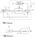
- a general training setup 10 for training a general neural network 12 for classification is shown in Fig. 1a.
- the neural network 12 is fed labeled data 14.
- the labeled data 14 is for example an image of an object to be classified, wherein the image is labeled with the correct class, i.e. the labeled data 14 includes the ground truth 18 of the image data 16 and the image data 16 itself.
- the image data 16 is inputted to the classifier and the ground truth 18 is sent to a loss function calculator 20.
- the classifier 12 processes the data representing an object to be classified and generates a classification identifier 22.
- the processing in the classifier includes applying weights to values as the data is fed through the classifier 12.
- the classification identifier 22 may be a feature vector, a classification vector, or a single value identifying a class.
- the loss function the classification identifier 22 is compared to the ground truth 18 using, e.g. a loss function.
- the result from the loss function 24 is then transferred to a weight adjustment function 26 that is configured to adjust the weights used in the classifier 12.
- the classifier 12 when the classifier 12 is fully trained it may be used as depicted in Fig. 2 , wherein a classification is performed by loading the data 30 to be classified into the classifier 12.
- the data 30 to be classified is in the same form as the labeled data used during training, but without the label.
- the classifier 12 then output data 32 identifying the class determined for the data inputted.
- the classifier may be any type of neural network, artificial intelligence, or machine learning scheme.
- an artificial intelligence includes a neural network, hence when we describes neural networks it also applies to any artificial intelligences including such neural networks.
- a neural network to be used as a classifier may be implemented in a lot of different ways known to the skilled person. Neural networks sometimes are referred to as artificial neural networks.
- One object of the present invention is to make training of a classifier less labour intensive.
- a method for training a classifier comprises:
- One advantage of the above method is that it enables training a classifier for a new set of sensor data using an already trained classifier operating on a first set of sensor data, wherein the data of the second set of sensor data represent the same object or event as the first set of sensor data and during a corresponding time period.
- the first set of sensor data sent to the tutor classifier is a subset of the first set of sensor data including the object or the event, wherein the subset of the first set of sensor data represents sensor data relating to a spatial position of the object or the event in a monitored environment, and wherein the second set of sensor data sent to the apprentice neural network represents a subset of the second sensor data, wherein the subset of the second sensor data represents data relating to the corresponding spatial position in the monitored environment as the subset of the first set of sensor data.
- the advantage of using the spatial position from the first set of sensor data of the object to classify may be that the identification of the corresponding object is facilitated in situations where multiple objects are present at least in the second data set. Further, the use of the spatial position may facilitate and/or speed up finding the object from the first set of sensor data in the second set of sensor data.
- the first set of sensor data and the second set of sensor data are generated by the same sensor.
- an image sensor may provide still image data and video data, i.e. in cases wherein the sensor is an image sensor the first set of sensor data may be a still image and the second set of sensor data may be a sequence of video frames.
- the first set of sensor data is generated by a first sensor and the second set of sensor data is generated by a second sensor. This is advantageous in cases when it is desired facilitating training classification of another type of sensor data than the available classifier is capable of classifying. By using such an embodiment, there is no need to go through the process of manually creating training data, hence the training process is facilitated.
- the first sensor and the second sensor are arranged to generate data from different types of sensor inputs. To train a classifier to classify data of a different type than an already trained classifier is trained on also facilitate the training process as there is no need to manually create a labelled training set of data for the type of data represented by the second set of data.
- the first sensor is an image sensor and wherein the second sensor is any sensor type from the group of radar sensor, audio sensor, sound field sensor, LIDAR sensor, sensor for laser absorption spectroscopy, sonar sensor, radiation sensor, X-ray sensor, ultra sound.
- the image sensor is a sensor registering visible light.
- the first sensor is a sensor registering visible light and the second sensor is a sensor registering infra-red light.
- the tutor classifier is based on a neural network and according to some embodiments the apprentice classifier is based on a neural network.
- a system arranged to train a classifier comprising a tutor classifier arranged to receive a first set of sensor data including data representing an object or an event in a monitored environment and to generate a classification of the object or event, an apprentice classifier arranged to be trained wherein the training includes receiving a second set of sensor data representing a corresponding time period as a time period represented by the first set of sensor data, a loss value calculator arranged to receive an output classification from the tutor classifier, to receive an output classification from the apprentice classifier, and to calculate a loss value identifying a difference between the two received classifications, and a weight adjuster arranged to adjust weights in the apprentice classifier in response to the loss value calculated by the loss value calculator.
- One advantage of the above system is that it enables training a classifier for a new set of sensor data using an already trained classifier operating on a first set of sensor data, wherein the data of the second set of sensor data represent the same object or event as the first set of sensor data and during a corresponding time period.
- the system further comprises a sensor generating both the first set of sensor data and the second set of sensor data.
- a sensor generating both the first set of sensor data and the second set of sensor data.
- system further comprises a first sensor generating the first set of sensor data and a second sensor generating the second set of sensor data. This is advantageous in cases when it is desired facilitating training classification of another type of sensor data than the available classifier is capable of classifying. By using such an embodiment, there is no need to go through the process of manually creating training data, hence the training process is facilitated.
- a sensor is an image sensor.
- the present invention relates to classifiers that are being configured to classify objects and/or events by means of processing data from a sensor.
- the invention relates to having a first classifier already configured to classify objects and/or events from a first set of data provided by a sensor to assist in configuring a second classifier to classify objects and/or events from a second set of data provided by the same or a different sensor.
- the first classifier may be seen as teaching the second classifier and therefore the first classifier will be referred to as tutor classifier and the second classifier will be referred to as apprentice classifier.
- the tutor classifier is configured to classify data from an image sensor, e.g. a sensor for capturing images from visible light or infra-red light.
- an image sensor e.g. a sensor for capturing images from visible light or infra-red light.
- One advantage of having the tutor classifier configured to classify objects and/or events based on data from a visible light image sensor is that there are a lot of labelled data sets already prepared for this type of data and, thus, this will facilitate the training of such a classifier. There may even be pre-configured classifiers that may be used.
- the apprentice classifier may be configured to be trained to classify data from any type of sensor for which it is possible to correlate a classification made by the tutor classifier.
- the apprentice classifier may be trained to classify data from the same sensor or same type of sensor as the tutor classifier is trained to classify, but in a different form.
- the apprentice classifier is to be trained to classify data from a second sensor.
- the second sensor may for example be a visible light image sensor, an infra-red light image sensor, a radar sensor, a microphone, a microphone matrix, a sound field sensor, ultra sound, a Lidar sensor, a sensor for laser absorption spectroscopy, a sonar sensor, a radiation sensor, an X-ray sensor, etc.
- Fig. 3 depicting an example of a system arranged for making one classifier configure or train another classifier to classify.
- the system includes a configured and/or trained tutor classification module 102 and an apprentice classification module 104 to be configured and/or trained.
- the tutor classification module 102 is arranged to receive sensor data from a first sensor 106 and the apprentice classification module 104 is arranged to receive data from a second sensor 108.
- the first sensor 106 is, in this example, an image sensor delivering two dimensional image of a scene.
- the tutor classification module includes an object detector 110, a cropping module 112, and a tutor classifier 114.
- the object detector 110 may be any kind of object detector arranged to detect objects in a two dimensional image that is known to the skilled person.
- the object detector 110 is arranged to detect objects appearing in the image of the scene captured in data received from the first sensor 106.
- the cropping module 112 is arranged to extract a subset of the data from the first sensor 106 and transmit the extracted subset of data to the tutor classifier 114.
- the subset to be extracted is determined by the position and size of the object detected in the object detector 110.
- the cropping area may be of rectangular shape and be somewhat larger than the object.
- the cropping module 112 In addition to cropping the data by extracting said subset of data and sending the subset of data to the tutor classifier the cropping module 112 transfer information of the position of the detected object to the apprentice classification module 104. Moreover, in addition to transferring the position of the detected object to the apprentice classification module the cropping module may be arranged to transfer any one of the following features: area of the cropped area, width of the cropped area, height of the cropped area, direction to the cropped area.
- the tutor classifier 114 processes the cropped image data and generates an indicator that indicates the class of the detected object.
- the indicator may be a feature vector, a classification vector, a single value or it may be a data set indicating the class and the likelihood of the object being correctly classified, i.e. the confidence value for the indicated class.
- the class indicator or a filtered version of the class indicator is then transferred to the apprentice classification module 104.
- the filtered version may be a class indicator in which a limited number or a single one class indicator having the best confidence value/s are transferred to the apprentice classification module.
- a class indicator may be stopped from being transferred if the confidence value is below a predetermined threshold.
- the apprentice classification module 104 includes a crop translator 116, a cropping module 118, an apprentice classifier 120, a loss function calculator 122, and a weight adjuster 124.
- the crop translator 116 is arranged to translate the information relating to the cropping performed in the cropping module 112 in the tutor classification module102 into a corresponding position represented in the data from the second sensor 108.
- FIG. 4a depicts an image 150 captured by an image sensor, e.g. visible light image sensor or infra-red image sensor and Fig. 4b depicts a representation 152 of sensor data from a radar sensor at a corresponding time period as the capturing of the image in Fig. 4a .
- the image in Fig. 4a shows two persons 154,156 in the captured scene.
- An object detector, such as the one 110 in the tutor classification module 102 will probably detect both persons 154,156, however, the system should only classify one object at a time.
- the classifying module is in the stage to process the person 156 to the right and the hatched area 158 indicates that this is the detected object and the cropping module 112 has determined the area to crop, indicated by the hatched area 158.
- the information relating to the cropping determined in the cropping module 112 is then transferred to the crop translator 116 of the apprentice classification module 104, as previously mentioned.
- the crop translator 116 will in this case translate the position to a corresponding direction in the data of the radar sensor, indicated by the hatched sector 160 in Fig. 4b .
- the angle ⁇ may be determined from the width of the cropping area 158 in Fig. 4a or may be determined on an independent object detection for the radar data in the determined direction.
- the cropping module 118 is arranged to extract a subset of data from the second sensor 108.
- the selection of the subset of data to be extracted is at least partially determined using data from the crop translator.
- the apprentice classifier 120 is arranged to receive the cropped data from the cropping module 118 and generate a value or a vector of values indicating an estimated class for the corresponding object in the data from the second sensor 108.
- the loss function calculator 122 is arranged to evaluate the result from the apprentice classifier 120 in comparison to the ground truth provided from the tutor classifier 114. In machine learning the ground truth is, for the example of classifiers, the class of the object which is provided as the correct class for the particular image, i.e.
- This evaluation results in an output that is used for adjustment of the processing in the apprentice classifier 120, e.g. by adjusting weights in various process steps.
- the weight adjuster 124 is arranged to use this evaluation result from the loss function 122 and generate the appropriate weight adjustments for the apprentice classifier 120 in order to get closer to a correct classification.
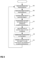
- FIG. 5 shows a portion of the training process relating to the processing of the data from the first sensor 106 and generating of data for use in training the classification of the data from the second sensor 108.
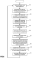
- Fig. 6 shows a portion of the training process relating to the processing of the data from the second sensor 108 and the adjustment of weights in the apprentice classifier using inputs from the processing of data from the first sensor 106.
- a training loop starts with the input of two data sets from the two sensors 106, 108. Accordingly the process receives data from the first sensor 106, step 202 in Fig. 5 , and from the second sensor 108, step 252 in Fig. 6 .
- the first sensor 106 being an image sensor as described above.
- the data registered by the two sensors 106, 108, are registered by each sensor 106, 108, at corresponding points in time, i.e. the data is captured at the two sensors, respectively, at a short temporal distance or for overlapping time periods in order to make it likely that the two sensors capture data relating to the same object, or event.
- step 202 the process continues by detecting an object in the data from the first sensor 106, step 206.
- the detected object is then analysed for cropping and a subset of data representing the detected object is selected, i.e. cropped, step 208.
- data relating to one of or any combination of the following features relating to the detected object is determined and transferred, step 210, for use in a cropping operation to be performed on the data from the second sensor 108 in the apprentice classification module104.
- the features are: a position of the detected object, an indication of the area occupied by the object, the width of the cropped area, the height of the cropped area.
- the cropped data from the first sensor is then inputted to the tutor classifier 114, step 212, and a classification identifier is generated, step 214, by the tutor classifier 114.
- the classification identifier relating to the detected object is then sent to the loss function 122 in the apprentice classification module 104, step 216.
- the process then returns to step 202 for receipt of new image data.
- the repetition of a training loop may be performed as fast as possible.
- the training may be limited to the classifications having good enough confidence values.
- the training is performed on live data and in some embodiments it is performed on recorded data that registered or captured at points in time that suggest that the data represents the same event or object.
- the sensor data from the second sensor is received, step 252, as previously mentioned.
- the features relating to the cropping and object detection described in connection with the description of Fig. 5 , is received from the tutor classification module 102, step 254.
- the features are translated to values that are relevant for the type of data delivered by the sensor in order to enable correlation between positions in the data sets from the two sensors 106, 108, step 256.
- Cropping parameters are then determined using at least some translated values from the tutor classification module 102, step 258.
- the data from the second sensor 108 is then cropped using these cropping parameters, step 260, and the cropped data is inputted into the apprentice classifier 120, step 262.
- the apprentice classifier 120 then generates a classification identifier of the object in the processed cropped data, step 264.
- the classification identifier generated by the apprentice classifier 120 is then received at the loss function calculator 122, where the loss function is calculated from the classification identifier received from the apprentice classifier 120 and the classification identifier received from the tutor classifier 114, step 266.
- the calculated loss function is then used for generating weight adjustments for the apprentice classifier, step 268.
- the weight adjustments are then introduced in the apprentice classifier in order to improve the classification accuracy, step 270.
- the process then returns to step 252 for receipt of new image data.
- the image data captured by the first sensor 106 and the data captured by the second sensor 108 should both include data representing the same object at the same moment in time, e.g. the data should be captured at essentially the same point in time or covering overlapping time periods.
- the apprentice classification module may be arranged to process a sequence of sensor data sets, i.e. a plurality of sensor data sets captured sequentially at different time points. Examples of this type of sequential data are, motion video, audio, radar, sequences of still images, etc.
- the apprentice classification module 704 includes a crop translator 116 similar to the one described in Fig. 3 and a cropping module 706.
- the cropping module may be arranged to initially find the object or the event in the sensor data by using the translated crop data from the tutor classification module and then track the object or the event initially found in order to crop relevant data.
- the cropped data could be a subset of data representing a tighter rectangle surrounding the object of interest. For some sensor data cropping of data makes no sense and will in those cases be skipped, e.g.
- the apprentice classification module further includes a buffer 708, a feature extractor 710, the apprentice classifier 120, the loss function 122, and the weight adjuster.
- the buffer 708 is arranged to buffer the sequence of cropped data from the sensor, or the sequence of data if no cropping is performed.
- the feature extractor 710 operates on the data in the buffer to find and extract features from the sequence, e.g. angular movement, change in distance, object speed, changes in shape of the object, movement characteristics, etc.
- the apprentice classifier 120, the loss function 122, and the weight adjuster are very much the same devices and/or modules as described in connection with Fig. 3 .
- the sensor data has been described as originating from different sensors.
- the sensor data received by the tutor classification module 102 and the sensor data received by the apprentice classification module 104; 704 may originate from the same sensor but delivering different sensor data.
- the tutor classification module 102 may receive image data representing a still picture and the apprentice classification module 104; 704 may receive motion video data, i.e. a sequence of video frames, from the same sensor.
- the advantages of training classification of objects in the video data based on a classification of an object in the still image may be the same as for the corresponding training using data from different sensors.
- An additional advantage may be that the training of classifying an object using motion video data is that motion patterns of the object may be added to a final classification system and that the likelihood of making a correct classification will be increased.
- Motion patterns may for instance be the gait of a human or an animal.
- the sensor data received by the tutor classification module 104; 704 may originate from the same sensor which is delivering both image data based on visible light and image data based on infrared light.
- Such a sensor may be an RGB-IR sensor.
Landscapes
- Engineering & Computer Science (AREA)
- Theoretical Computer Science (AREA)
- Physics & Mathematics (AREA)
- General Physics & Mathematics (AREA)
- Data Mining & Analysis (AREA)
- Evolutionary Computation (AREA)
- Artificial Intelligence (AREA)
- Life Sciences & Earth Sciences (AREA)
- General Engineering & Computer Science (AREA)
- Computer Vision & Pattern Recognition (AREA)
- Health & Medical Sciences (AREA)
- General Health & Medical Sciences (AREA)
- Software Systems (AREA)
- Computing Systems (AREA)
- Multimedia (AREA)
- Bioinformatics & Cheminformatics (AREA)
- Evolutionary Biology (AREA)
- Bioinformatics & Computational Biology (AREA)
- Biomedical Technology (AREA)
- Biophysics (AREA)
- Mathematical Physics (AREA)
- Computational Linguistics (AREA)
- Molecular Biology (AREA)
- Databases & Information Systems (AREA)
- Medical Informatics (AREA)
- Human Computer Interaction (AREA)
- Image Analysis (AREA)
- Information Retrieval, Db Structures And Fs Structures Therefor (AREA)
Abstract
Description
- The present invention relates to a method and system for training a neural network to classify objects or events.
- Classification of objects and/or of events may be achieved by means of a neural network, sometimes also referred to as artificial intelligence Al. The trend right now is of an increased use of these technologies for classifying objects or events from captured still images or video. These classifying neural networks are often used in applications like character recognition, monitoring, surveillance, image analysis, natural language processing etc. There are many neural network algorithms/technologies that may be used for classifying objects, e.g. Convolutional Neural Networks, Recurrent Neural Networks, etc.
- A
general training setup 10 for training a generalneural network 12 for classification is shown in Fig. 1a. Theneural network 12 is fed labeleddata 14. The labeleddata 14 is for example an image of an object to be classified, wherein the image is labeled with the correct class, i.e. the labeleddata 14 includes theground truth 18 of theimage data 16 and theimage data 16 itself. Theimage data 16 is inputted to the classifier and theground truth 18 is sent to aloss function calculator 20. Theclassifier 12 processes the data representing an object to be classified and generates aclassification identifier 22. The processing in the classifier includes applying weights to values as the data is fed through theclassifier 12. Theclassification identifier 22 may be a feature vector, a classification vector, or a single value identifying a class. In the loss function theclassification identifier 22 is compared to theground truth 18 using, e.g. a loss function. The result from theloss function 24 is then transferred to aweight adjustment function 26 that is configured to adjust the weights used in theclassifier 12. Then when theclassifier 12 is fully trained it may be used as depicted inFig. 2 , wherein a classification is performed by loading thedata 30 to be classified into theclassifier 12. Thedata 30 to be classified is in the same form as the labeled data used during training, but without the label. Theclassifier 12 thenoutput data 32 identifying the class determined for the data inputted. - To achieve a properly trained classifier a very large number of labeled data instances is required, e.g. labeled images. Generally hundreds of thousands of instances of labeled data is required, in many cases even millions. This training data is very cumbersome to generate. For some classifications you may buy large labeled data sets. The most common data sets includes images that are classified. One problem with these existing data sets is that they may not be labeled with the classes you would like to train your classifier to recognize. Another problem with the existing data sets is that they may not use the form of input data that you would like to make your classification on.
- The classifier may be any type of neural network, artificial intelligence, or machine learning scheme. In the present description an artificial intelligence includes a neural network, hence when we describes neural networks it also applies to any artificial intelligences including such neural networks. A neural network to be used as a classifier may be implemented in a lot of different ways known to the skilled person. Neural networks sometimes are referred to as artificial neural networks.
- One object of the present invention is to make training of a classifier less labour intensive.
- The object is achieved by means of a method for training a classifier according to
claim 1. Further embodiments of the invention are presented in the dependent claims. - More precisely, according to one aspect of the invention, a method for training a classifier comprises:
- receiving a first set of sensor data including data representing an object or an event in a monitored environment,
- receiving a second set of sensor data representing a corresponding time period as a time period represented by the first set of sensor data,
- inputting to a tutor classifier data representing the first set of data and including data representing the object or the event,
- generating a classification of the object or event in the tutor classifier,
- receiving the second set of sensor data at an apprentice classifier training process,
- receiving the classification generated in the tutor classifier at the apprentice classifier training process,
- training the apprentice classifier in the apprentice classifier training process using the second set of sensor data as input and using the classification received from the tutor classifier as a ground-truth for the classification of the second set of sensor data.
- One advantage of the above method is that it enables training a classifier for a new set of sensor data using an already trained classifier operating on a first set of sensor data, wherein the data of the second set of sensor data represent the same object or event as the first set of sensor data and during a corresponding time period.
- In other embodiments the first set of sensor data sent to the tutor classifier is a subset of the first set of sensor data including the object or the event, wherein the subset of the first set of sensor data represents sensor data relating to a spatial position of the object or the event in a monitored environment, and wherein the second set of sensor data sent to the apprentice neural network represents a subset of the second sensor data, wherein the subset of the second sensor data represents data relating to the corresponding spatial position in the monitored environment as the subset of the first set of sensor data. The advantage of using the spatial position from the first set of sensor data of the object to classify may be that the identification of the corresponding object is facilitated in situations where multiple objects are present at least in the second data set. Further, the use of the spatial position may facilitate and/or speed up finding the object from the first set of sensor data in the second set of sensor data.
- In some embodiments the first set of sensor data and the second set of sensor data are generated by the same sensor. This is advantageous for sensors that are enabled to provide various types of sensor data. For example, an image sensor may provide still image data and video data, i.e. in cases wherein the sensor is an image sensor the first set of sensor data may be a still image and the second set of sensor data may be a sequence of video frames.
- In yet other embodiments the first set of sensor data is generated by a first sensor and the second set of sensor data is generated by a second sensor. This is advantageous in cases when it is desired facilitating training classification of another type of sensor data than the available classifier is capable of classifying. By using such an embodiment, there is no need to go through the process of manually creating training data, hence the training process is facilitated. In other embodiments the first sensor and the second sensor are arranged to generate data from different types of sensor inputs. To train a classifier to classify data of a different type than an already trained classifier is trained on also facilitate the training process as there is no need to manually create a labelled training set of data for the type of data represented by the second set of data.
- According to some embodiments the first sensor is an image sensor and wherein the second sensor is any sensor type from the group of radar sensor, audio sensor, sound field sensor, LIDAR sensor, sensor for laser absorption spectroscopy, sonar sensor, radiation sensor, X-ray sensor, ultra sound. According to yet other embodiments the image sensor is a sensor registering visible light. In other embodiments the first sensor is a sensor registering visible light and the second sensor is a sensor registering infra-red light.
- In some embodiments the tutor classifier is based on a neural network and according to some embodiments the apprentice classifier is based on a neural network.
- According to another aspect of the invention a system arranged to train a classifier comprising a tutor classifier arranged to receive a first set of sensor data including data representing an object or an event in a monitored environment and to generate a classification of the object or event, an apprentice classifier arranged to be trained wherein the training includes receiving a second set of sensor data representing a corresponding time period as a time period represented by the first set of sensor data, a loss value calculator arranged to receive an output classification from the tutor classifier, to receive an output classification from the apprentice classifier, and to calculate a loss value identifying a difference between the two received classifications, and a weight adjuster arranged to adjust weights in the apprentice classifier in response to the loss value calculated by the loss value calculator. One advantage of the above system is that it enables training a classifier for a new set of sensor data using an already trained classifier operating on a first set of sensor data, wherein the data of the second set of sensor data represent the same object or event as the first set of sensor data and during a corresponding time period.
- In some embodiments the system further comprises a sensor generating both the first set of sensor data and the second set of sensor data. This is advantages for sensors that are enabled to provide various types of sensor data. For example, an image sensor may provide still image data and video data, i.e. in cases wherein the sensor is an image sensor the first set of sensor data may be still image and the second set of sensor data may be a sequence of video frames.
- In other embodiments the system further comprises a first sensor generating the first set of sensor data and a second sensor generating the second set of sensor data. This is advantageous in cases when it is desired facilitating training classification of another type of sensor data than the available classifier is capable of classifying. By using such an embodiment, there is no need to go through the process of manually creating training data, hence the training process is facilitated.
- In some embodiments a sensor is an image sensor.
- A further scope of applicability of the present invention will become apparent from the detailed description given below. However, it should be understood that the detailed description and specific examples, while indicating preferred embodiments of the invention, are given by way of illustration only, since various changes and modifications within the scope of the invention will become apparent to those skilled in the art from this detailed description. Hence, it is to be understood that this invention is not limited to the particular component parts of the device described or steps of the methods described as such device and method may vary. It is also to be understood that the terminology used herein is for purpose of describing particular embodiments only, and is not intended to be limiting. It must be noted that, as used in the specification and the appended claim, the articles "a," "an," "the," and "said" are intended to mean that there are one or more of the elements unless the context clearly dictates otherwise. Thus, for example, reference to "a sensor" or "the sensor" may include several sensors, and the like. Furthermore, the word "comprising" does not exclude other elements or steps.
- Other features and advantages of the present invention will become apparent from the following detailed description of a presently preferred embodiment, with reference to the accompanying drawings, in which:
-
Fig. 1 is a schematic block diagram of a training system for training a classifier in accordance with prior art, -
Fig. 2 is a schematic block diagram of a prior art classifier when used after training, -
Fig. 3 is a schematic block diagram of a training system for training a classifier according to an embodiment of the invention, -
Fig. 4a is a schematic view of sensor data of a scene captured by an image sensor, -
Fig. 4b is a schematic view of sensor data of the corresponding scene ofFig. 4a , but captured by a radar sensor, -
Fig. 5 is a flowchart of a classification process being part of the training process according to an embodiment of the invention, -
Fig. 6 is a flowchart of a learning process for an apprentice neural network being part of the training process according to an embodiment of the invention, and -
Fig. 7 is a schematic block diagram of an apprentice portion of the training system according to an alternative embodiment. - Further, in the figures like reference characters designate like or corresponding parts throughout the several figures.
- The present invention relates to classifiers that are being configured to classify objects and/or events by means of processing data from a sensor. In particular the invention relates to having a first classifier already configured to classify objects and/or events from a first set of data provided by a sensor to assist in configuring a second classifier to classify objects and/or events from a second set of data provided by the same or a different sensor. The first classifier may be seen as teaching the second classifier and therefore the first classifier will be referred to as tutor classifier and the second classifier will be referred to as apprentice classifier.
- In some embodiments the tutor classifier is configured to classify data from an image sensor, e.g. a sensor for capturing images from visible light or infra-red light. One advantage of having the tutor classifier configured to classify objects and/or events based on data from a visible light image sensor is that there are a lot of labelled data sets already prepared for this type of data and, thus, this will facilitate the training of such a classifier. There may even be pre-configured classifiers that may be used.
- The apprentice classifier may be configured to be trained to classify data from any type of sensor for which it is possible to correlate a classification made by the tutor classifier. The apprentice classifier may be trained to classify data from the same sensor or same type of sensor as the tutor classifier is trained to classify, but in a different form. According to some embodiments the apprentice classifier is to be trained to classify data from a second sensor. The second sensor may for example be a visible light image sensor, an infra-red light image sensor, a radar sensor, a microphone, a microphone matrix, a sound field sensor, ultra sound, a Lidar sensor, a sensor for laser absorption spectroscopy, a sonar sensor, a radiation sensor, an X-ray sensor, etc.
- Now referring to
Fig. 3 depicting an example of a system arranged for making one classifier configure or train another classifier to classify. The system includes a configured and/or trainedtutor classification module 102 and anapprentice classification module 104 to be configured and/or trained. Thetutor classification module 102 is arranged to receive sensor data from afirst sensor 106 and theapprentice classification module 104 is arranged to receive data from asecond sensor 108. Thefirst sensor 106 is, in this example, an image sensor delivering two dimensional image of a scene. - The tutor classification module includes an
object detector 110, acropping module 112, and atutor classifier 114. Theobject detector 110 may be any kind of object detector arranged to detect objects in a two dimensional image that is known to the skilled person. Theobject detector 110 is arranged to detect objects appearing in the image of the scene captured in data received from thefirst sensor 106. Thecropping module 112 is arranged to extract a subset of the data from thefirst sensor 106 and transmit the extracted subset of data to thetutor classifier 114. The subset to be extracted is determined by the position and size of the object detected in theobject detector 110. The cropping area may be of rectangular shape and be somewhat larger than the object. In addition to cropping the data by extracting said subset of data and sending the subset of data to the tutor classifier thecropping module 112 transfer information of the position of the detected object to theapprentice classification module 104. Moreover, in addition to transferring the position of the detected object to the apprentice classification module the cropping module may be arranged to transfer any one of the following features: area of the cropped area, width of the cropped area, height of the cropped area, direction to the cropped area. - The
tutor classifier 114 processes the cropped image data and generates an indicator that indicates the class of the detected object. The indicator may be a feature vector, a classification vector, a single value or it may be a data set indicating the class and the likelihood of the object being correctly classified, i.e. the confidence value for the indicated class. The class indicator or a filtered version of the class indicator is then transferred to theapprentice classification module 104. The filtered version may be a class indicator in which a limited number or a single one class indicator having the best confidence value/s are transferred to the apprentice classification module. Moreover, in some embodiments a class indicator may be stopped from being transferred if the confidence value is below a predetermined threshold. - The
apprentice classification module 104 includes acrop translator 116, acropping module 118, anapprentice classifier 120, aloss function calculator 122, and aweight adjuster 124. Thecrop translator 116 is arranged to translate the information relating to the cropping performed in thecropping module 112 in the tutor classification module102 into a corresponding position represented in the data from thesecond sensor 108. - This translation is illustrated in
Figs 4a-b in whichFig. 4a depicts animage 150 captured by an image sensor, e.g. visible light image sensor or infra-red image sensor andFig. 4b depicts arepresentation 152 of sensor data from a radar sensor at a corresponding time period as the capturing of the image inFig. 4a . The image inFig. 4a shows two persons 154,156 in the captured scene. An object detector, such as the one 110 in thetutor classification module 102 will probably detect both persons 154,156, however, the system should only classify one object at a time. Let us assume that the classifying module is in the stage to process theperson 156 to the right and the hatchedarea 158 indicates that this is the detected object and thecropping module 112 has determined the area to crop, indicated by the hatchedarea 158. The information relating to the cropping determined in thecropping module 112 is then transferred to thecrop translator 116 of theapprentice classification module 104, as previously mentioned. Thecrop translator 116 will in this case translate the position to a corresponding direction in the data of the radar sensor, indicated by the hatchedsector 160 inFig. 4b . The angle α may be determined from the width of thecropping area 158 inFig. 4a or may be determined on an independent object detection for the radar data in the determined direction. - Now returning to
Fig. 3 and the description of the features of theapprentice classification module 104. Thecropping module 118 is arranged to extract a subset of data from thesecond sensor 108. The selection of the subset of data to be extracted is at least partially determined using data from the crop translator. Theapprentice classifier 120 is arranged to receive the cropped data from thecropping module 118 and generate a value or a vector of values indicating an estimated class for the corresponding object in the data from thesecond sensor 108. Theloss function calculator 122 is arranged to evaluate the result from theapprentice classifier 120 in comparison to the ground truth provided from thetutor classifier 114. In machine learning the ground truth is, for the example of classifiers, the class of the object which is provided as the correct class for the particular image, i.e. by manual labelling of objects. This evaluation results in an output that is used for adjustment of the processing in theapprentice classifier 120, e.g. by adjusting weights in various process steps. Theweight adjuster 124 is arranged to use this evaluation result from theloss function 122 and generate the appropriate weight adjustments for theapprentice classifier 120 in order to get closer to a correct classification. - Now referring to
Figs 5 and6 showing an example process for the training of a classifier.Fig. 5 shows a portion of the training process relating to the processing of the data from thefirst sensor 106 and generating of data for use in training the classification of the data from thesecond sensor 108.Fig. 6 shows a portion of the training process relating to the processing of the data from thesecond sensor 108 and the adjustment of weights in the apprentice classifier using inputs from the processing of data from thefirst sensor 106. A training loop starts with the input of two data sets from the twosensors first sensor 106,step 202 inFig. 5 , and from thesecond sensor 108,step 252 inFig. 6 . Thefirst sensor 106 being an image sensor as described above. The data registered by the twosensors sensor - Now let us take a look at the processing of the data from the
first sensor 106 inFig. 5 . After the image sensor data have been received, when it has been captured by thefirst sensor 106,step 202, the process continues by detecting an object in the data from thefirst sensor 106,step 206. The detected object is then analysed for cropping and a subset of data representing the detected object is selected, i.e. cropped,step 208. Further, data relating to one of or any combination of the following features relating to the detected object is determined and transferred,step 210, for use in a cropping operation to be performed on the data from thesecond sensor 108 in the apprentice classification module104. The features are: a position of the detected object, an indication of the area occupied by the object, the width of the cropped area, the height of the cropped area. - The cropped data from the first sensor is then inputted to the
tutor classifier 114,step 212, and a classification identifier is generated,step 214, by thetutor classifier 114. The classification identifier relating to the detected object is then sent to theloss function 122 in theapprentice classification module 104,step 216. The process then returns to step 202 for receipt of new image data. The repetition of a training loop may be performed as fast as possible. In some embodiment, the training may be limited to the classifications having good enough confidence values. In some embodiments the training is performed on live data and in some embodiments it is performed on recorded data that registered or captured at points in time that suggest that the data represents the same event or object. Continuing the description of the training process by looking at the processing of the data from the second sensor inFig. 6 , the sensor data from the second sensor is received,step 252, as previously mentioned. Then the features relating to the cropping and object detection, described in connection with the description ofFig. 5 , is received from thetutor classification module 102,step 254. The features are translated to values that are relevant for the type of data delivered by the sensor in order to enable correlation between positions in the data sets from the twosensors step 256. Cropping parameters are then determined using at least some translated values from thetutor classification module 102,step 258. The data from thesecond sensor 108 is then cropped using these cropping parameters,step 260, and the cropped data is inputted into theapprentice classifier 120,step 262. Theapprentice classifier 120 then generates a classification identifier of the object in the processed cropped data,step 264. The classification identifier generated by theapprentice classifier 120 is then received at theloss function calculator 122, where the loss function is calculated from the classification identifier received from theapprentice classifier 120 and the classification identifier received from thetutor classifier 114,step 266. The calculated loss function is then used for generating weight adjustments for the apprentice classifier,step 268. The weight adjustments are then introduced in the apprentice classifier in order to improve the classification accuracy,step 270. The process then returns to step 252 for receipt of new image data. - As described above in relation to some embodiments, the image data captured by the
first sensor 106 and the data captured by thesecond sensor 108 should both include data representing the same object at the same moment in time, e.g. the data should be captured at essentially the same point in time or covering overlapping time periods. - In some embodiments of the invention the apprentice classification module may be arranged to process a sequence of sensor data sets, i.e. a plurality of sensor data sets captured sequentially at different time points. Examples of this type of sequential data are, motion video, audio, radar, sequences of still images, etc.
- An example of an apprentice classification module arranged to handle these situations, i.e. processing a sequence of sensor data sets, are depicted in
Fig 7 . Theapprentice classification module 704 includes acrop translator 116 similar to the one described inFig. 3 and acropping module 706. The cropping module may be arranged to initially find the object or the event in the sensor data by using the translated crop data from the tutor classification module and then track the object or the event initially found in order to crop relevant data. When the data relates to motion video the cropped data could be a subset of data representing a tighter rectangle surrounding the object of interest. For some sensor data cropping of data makes no sense and will in those cases be skipped, e.g. sensor data from a single microphone or other sensor data having no spatial information relating a data point spatially to another data point. The apprentice classification module further includes abuffer 708, afeature extractor 710, theapprentice classifier 120, theloss function 122, and the weight adjuster. Thebuffer 708 is arranged to buffer the sequence of cropped data from the sensor, or the sequence of data if no cropping is performed. Thefeature extractor 710 operates on the data in the buffer to find and extract features from the sequence, e.g. angular movement, change in distance, object speed, changes in shape of the object, movement characteristics, etc. These features from the feature extractor will then be used as inputs to the apprentice classifier which will be trained on these features in order to identify them as belonging to a class identified in thetutor classification module 102. Theapprentice classifier 120, theloss function 122, and the weight adjuster are very much the same devices and/or modules as described in connection withFig. 3 . - In all previous example embodiments the sensor data has been described as originating from different sensors. However, the sensor data received by the
tutor classification module 102 and the sensor data received by theapprentice classification module 104; 704 may originate from the same sensor but delivering different sensor data. For example, thetutor classification module 102 may receive image data representing a still picture and theapprentice classification module 104; 704 may receive motion video data, i.e. a sequence of video frames, from the same sensor. The advantages of training classification of objects in the video data based on a classification of an object in the still image may be the same as for the corresponding training using data from different sensors. An additional advantage may be that the training of classifying an object using motion video data is that motion patterns of the object may be added to a final classification system and that the likelihood of making a correct classification will be increased. Motion patterns may for instance be the gait of a human or an animal. In another example the sensor data received by thetutor classification module 104; 704, may originate from the same sensor which is delivering both image data based on visible light and image data based on infrared light. Such a sensor may be an RGB-IR sensor.
Claims (8)
- Method for training a classifier, the method comprising:generating, by an image sensor (106, 108) registering visible light and infra-red light, image data based on visible light including data representing an object or an event in a monitored environment,generating, by the image sensor (106, 108), image data based on infra-red light representing a corresponding time period as a time period represented by the image data based on visible light,inputting (202) to a tutor classifier (114) data representing the image data based on visible light including data representing the object or the event,generating (214) a classification of the object or event in the tutor classifier (114),receiving (252) the image data based on infra-red light at an apprentice classifier training process,receiving (216) the classification generated in the tutor classifier (114) at the apprentice classifier training process,training (266, 268, 270) the apprentice classifier (114) in the apprentice classifier training process using the image data based on infra-red light as input and using the classification received from the tutor classifier (114) as a ground-truth for the classification of the image data based on infra-red light.
- Method according to claim 1, wherein the tutor classifier (114) is based on a neural network.
- Method according to any one of claims 1 and 2, wherein the apprentice classifier (120) is based on a neural network.
- Method according to any one of claims 1-3, further comprising:detecting (206) at an object detector (110) an object appearing in an image of the scene captured in said first set of sensor data,cropping (208) at a first cropping module (112) from the first set of sensor data a subset of data representing the detected object, a cropping area thereof being determined by the position and size of the detected object,determining (210) at said first cropping module (112) features of said cropping area, said features comprising a position of the detected object, an indication of the area occupied by the object, a width of the cropping area, a height of the cropping area and/or a direction of the cropping area, anddetermining (258) at a second cropping module (118) cropping parameters, wherein the image data based on infra-red light is then cropped (260) using said cropping parameters,wherein, in the act of training the apprentice classifier, the cropped image data based on infra-red light is used as input (262).
- System arranged to train a classifier, the system comprising:an image sensor (106, 108) registering visible light and infra-red light arranged to generate image data based on visible light including data representing an object or an event in a monitored environment and to generate image data based on infra-red light representing a corresponding time period as a time period represented by the image data based on visible light,a tutor classifier (114) arranged to receive the image data based on visible light, and to generate a classification of the object or event,an apprentice classifier (120) arranged to be trained wherein the training includes receiving the image data based on infra-red light,a loss value calculator (122) arranged to receive an output classification from the tutor classifier (114), to receive an output classification from the apprentice classifier (120), and to calculate a loss value identifying a difference between the two received classifications, anda weight adjuster (124) arranged to adjust weights in the apprentice classifier (120) in response to the loss value calculated by the loss value calculator.
- System according to claim 5, wherein the tutor classifier (114) is based on a neural network.
- System according to any one of claims 5 and 6, wherein the apprentice classifier 8120) is based on a neural network.
- System according to any one of claims 5-7, further comprising:an object detector (110) arranged to detect an object appearing in an image of the scene captured in said first set of sensor data,a first cropping module (112) arranged to crop from image data based on visible light a subset of data representing the detected object, a cropping area thereof being determined by the position and size of the detected object, said cropping module (112) further being arranged to determine features of said cropping area, said features comprising a position of the detected object, an indication of the area occupied by the object, a width of the cropping area, a height of the cropping area and/or a direction of the cropping area, anda second cropping module (118) arranged to determine cropping parameters, wherein the image data based on infra-red light is then cropped using said cropping parameters.
Priority Applications (1)
| Application Number | Priority Date | Filing Date | Title |
|---|---|---|---|
| EP22213941.2A EP4181085B1 (en) | 2017-06-30 | 2017-06-30 | Method and system for training a neural network to classify objects or events |
Applications Claiming Priority (2)
| Application Number | Priority Date | Filing Date | Title |
|---|---|---|---|
| EP22213941.2A EP4181085B1 (en) | 2017-06-30 | 2017-06-30 | Method and system for training a neural network to classify objects or events |
| EP17178915.9A EP3422255B1 (en) | 2017-06-30 | 2017-06-30 | Method and system for training a neural network to classify objects or events |
Related Parent Applications (2)
| Application Number | Title | Priority Date | Filing Date |
|---|---|---|---|
| EP17178915.9A Division EP3422255B1 (en) | 2017-06-30 | 2017-06-30 | Method and system for training a neural network to classify objects or events |
| EP17178915.9A Division-Into EP3422255B1 (en) | 2017-06-30 | 2017-06-30 | Method and system for training a neural network to classify objects or events |
Publications (3)
| Publication Number | Publication Date |
|---|---|
| EP4181085A1 true EP4181085A1 (en) | 2023-05-17 |
| EP4181085C0 EP4181085C0 (en) | 2025-05-28 |
| EP4181085B1 EP4181085B1 (en) | 2025-05-28 |
Family
ID=59296703
Family Applications (2)
| Application Number | Title | Priority Date | Filing Date |
|---|---|---|---|
| EP22213941.2A Active EP4181085B1 (en) | 2017-06-30 | 2017-06-30 | Method and system for training a neural network to classify objects or events |
| EP17178915.9A Active EP3422255B1 (en) | 2017-06-30 | 2017-06-30 | Method and system for training a neural network to classify objects or events |
Family Applications After (1)
| Application Number | Title | Priority Date | Filing Date |
|---|---|---|---|
| EP17178915.9A Active EP3422255B1 (en) | 2017-06-30 | 2017-06-30 | Method and system for training a neural network to classify objects or events |
Country Status (3)
| Country | Link |
|---|---|
| US (1) | US10635936B2 (en) |
| EP (2) | EP4181085B1 (en) |
| CN (1) | CN109214261B (en) |
Families Citing this family (13)
| Publication number | Priority date | Publication date | Assignee | Title |
|---|---|---|---|---|
| EP3667557B1 (en) * | 2018-12-13 | 2021-06-16 | Axis AB | Method and device for tracking an object |
| US12094160B2 (en) * | 2019-04-22 | 2024-09-17 | Nec Corporation | Object detection apparatus, object detection system, object detection method, and non-transitory computer readable medium storing program |
| US20220277552A1 (en) * | 2019-07-11 | 2022-09-01 | Nec Corporation | Object sensing device, learning method, and recording medium |
| FR3100358B1 (en) * | 2019-08-27 | 2021-09-03 | Thales Sa | Method for assisting in the detection of associated elements, device and platform |
| EP3800581A1 (en) | 2019-10-03 | 2021-04-07 | Axis AB | A method and apparatus for generating an object classification for an object |
| DE102019218613B4 (en) * | 2019-11-29 | 2021-11-11 | Volkswagen Aktiengesellschaft | Object classification method, object classification circuit, motor vehicle |
| US20210209144A1 (en) * | 2020-01-03 | 2021-07-08 | International Business Machines Corporation | Internet of things sensor equivalence ontology |
| EP3920082A1 (en) * | 2020-06-04 | 2021-12-08 | TOMRA Sorting GmbH | Method and system for training a neural network-implemented sensor system to classify objects in a bulk flow |
| CN112054967A (en) * | 2020-08-07 | 2020-12-08 | 北京邮电大学 | Network traffic classification method and device, electronic equipment and storage medium |
| US12488250B2 (en) | 2020-11-02 | 2025-12-02 | International Business Machines Corporation | Weight repetition on RPU crossbar arrays |
| CN112598050A (en) * | 2020-12-18 | 2021-04-02 | 四川省成都生态环境监测中心站 | Ecological environment data quality control method |
| US12125081B2 (en) | 2021-11-05 | 2024-10-22 | Target Brands, Inc. | Shopping cart with sound-based validation |
| CN116204642B (en) * | 2023-03-06 | 2023-10-27 | 上海阅文信息技术有限公司 | Intelligent character implicit attribute recognition analysis method, system and application in digital reading |
Family Cites Families (9)
| Publication number | Priority date | Publication date | Assignee | Title |
|---|---|---|---|---|
| US6968294B2 (en) * | 2001-03-15 | 2005-11-22 | Koninklijke Philips Electronics N.V. | Automatic system for monitoring person requiring care and his/her caretaker |
| US20100210975A1 (en) * | 2009-01-21 | 2010-08-19 | SwimSense, LLC | Multi-state performance monitoring system |
| US9940533B2 (en) * | 2014-09-30 | 2018-04-10 | Qualcomm Incorporated | Scanning window for isolating pixel values in hardware for computer vision operations |
| US9838635B2 (en) * | 2014-09-30 | 2017-12-05 | Qualcomm Incorporated | Feature computation in a sensor element array |
| DE102015212953B4 (en) * | 2015-07-10 | 2024-08-22 | Siemens Healthineers Ag | Artificial neural networks for the classification of medical image data sets |
| EP3136289A1 (en) * | 2015-08-28 | 2017-03-01 | Thomson Licensing | Method and device for classifying an object of an image and corresponding computer program product and computer-readable medium |
| US10289925B2 (en) * | 2016-11-29 | 2019-05-14 | Sap Se | Object classification in image data using machine learning models |
| US10282639B2 (en) * | 2016-11-29 | 2019-05-07 | Sap Se | Object detection in image data using depth segmentation |
| US20180314253A1 (en) * | 2017-05-01 | 2018-11-01 | Mentor Graphics Development (Deutschland) Gmbh | Embedded automotive perception with machine learning classification of sensor data |
-
2017
- 2017-06-30 EP EP22213941.2A patent/EP4181085B1/en active Active
- 2017-06-30 EP EP17178915.9A patent/EP3422255B1/en active Active
-
2018
- 2018-06-19 US US16/011,688 patent/US10635936B2/en active Active
- 2018-06-28 CN CN201810685772.1A patent/CN109214261B/en active Active
Non-Patent Citations (5)
| Title |
|---|
| "Network and Parallel Computing", vol. 8681, 1 January 2014, SPRINGER INTERNATIONAL PUBLISHING, Cham, ISBN: 978-3-642-24784-2, ISSN: 0302-9743, article CHETAK KANDASWAMY ET AL: "Improving Deep Neural Network Performance by Reusing Features Trained with Transductive Transference", pages: 265 - 272, XP055425704, 032548, DOI: 10.1007/978-3-319-11179-7_34 * |
| DIANE COOK ET AL: "Transfer learning for activity recognition: a survey", KNOWLEDGE AND INFORMATION SYSTEMS, vol. 36, no. 3, 7 June 2013 (2013-06-07), GB, pages 537 - 556, XP055500532, ISSN: 0219-1377, DOI: 10.1007/s10115-013-0665-3 * |
| KURZ MARC ET AL: "Real-Time Transfer and Evaluation of Activity Recognition Capabilities in an Opportunistic System", ADAPTIVE 2011 : THE THIRD INTERNATIONAL CONFERENCE ON ADAPTIVE AND SELF-ADAPTIVE SYSTEMS AND APPLICATIONS, 30 September 2011 (2011-09-30), pages 73 - 78, XP055792619, ISBN: 978-1-61208-156-4, Retrieved from the Internet <URL:http://citeseerx.ist.psu.edu/viewdoc/download?doi=10.1.1.417.461&rep=rep1&type=pdf> * |
| LU JIE ET AL: "Transfer learning using computational intelligence: A survey", KNOWLEDGE-BASED SYSTEMS, ELSEVIER, AMSTERDAM, NL, vol. 80, 22 January 2015 (2015-01-22), pages 14 - 23, XP029583969, ISSN: 0950-7051, DOI: 10.1016/J.KNOSYS.2015.01.010 * |
| SINNO JIALIN PAN ET AL: "A Survey on Transfer Learning", IEEE TRANSACTIONS ON KNOWLEDGE AND DATA ENGINEERING, IEEE SERVICE CENTER, LOS ALAMITOS, CA, US, vol. 22, no. 10, 1 October 2010 (2010-10-01), pages 1345 - 1359, XP011296423, ISSN: 1041-4347 * |
Also Published As
| Publication number | Publication date |
|---|---|
| EP3422255A1 (en) | 2019-01-02 |
| US10635936B2 (en) | 2020-04-28 |
| CN109214261B (en) | 2020-12-01 |
| EP4181085C0 (en) | 2025-05-28 |
| CN109214261A (en) | 2019-01-15 |
| EP4181085B1 (en) | 2025-05-28 |
| US20190005353A1 (en) | 2019-01-03 |
| EP3422255B1 (en) | 2023-03-15 |
Similar Documents
| Publication | Publication Date | Title |
|---|---|---|
| US10635936B2 (en) | Method and system for training a neural network to classify objects or events | |
| US11195038B2 (en) | Device and a method for extracting dynamic information on a scene using a convolutional neural network | |
| US10614310B2 (en) | Behavior recognition | |
| TWI749113B (en) | Methods, systems and computer program products for generating alerts in a video surveillance system | |
| US9560323B2 (en) | Method and system for metadata extraction from master-slave cameras tracking system | |
| JP6032921B2 (en) | Object detection apparatus and method, and program | |
| US20070116364A1 (en) | Apparatus and method for feature recognition | |
| US20150262068A1 (en) | Event detection apparatus and event detection method | |
| KR102653485B1 (en) | Electronic apparatus for building fire detecting model and method thereof | |
| CN110443824A (en) | Method and apparatus for generating information | |
| CN111626240B (en) | Face image recognition method, device and equipment and readable storage medium | |
| CN110991385A (en) | Method and device for identifying ship driving track and electronic equipment | |
| KR20200009530A (en) | System and method for detecting abnormal object | |
| Gonzalez-Trejo et al. | Dense crowds detection and surveillance with drones using density maps | |
| Kabir et al. | Deep learning inspired vision based frameworks for drone detection | |
| KR20220019377A (en) | Drone detection apparatus using deep learning and method thereof | |
| KR20230056832A (en) | Method for building data set for a CNN-based AI classification model | |
| CN111291597A (en) | Image-based crowd situation analysis method, device, equipment and system | |
| CN113837087A (en) | Animal target detection system and method based on YOLOv3 | |
| Srinivas et al. | Intelligent surveillance with real time object detection coupled with distance estimation and voice alerts | |
| Chen et al. | Social distance monitoring of site workers for COVID-19 using context-guided data augmentation, deep learning, and homography transformation | |
| US20240273908A1 (en) | Video monitoring device, and method, computer program and storage medium for retraining a video monitoring device | |
| Yusuf et al. | Multiple Vehicle Detection and Tracking via RetinaNet with KLT Tracker | |
| Kumar et al. | Human Face Recognition and Detection System with Genetic and Ant Colony Optimization Algorithm | |
| KR20200123323A (en) | Method for segmentation of occluded pig objects using rotated bounding boxes based on yolo algorithm |
Legal Events
| Date | Code | Title | Description |
|---|---|---|---|
| PUAI | Public reference made under article 153(3) epc to a published international application that has entered the european phase |
Free format text: ORIGINAL CODE: 0009012 |
|
| STAA | Information on the status of an ep patent application or granted ep patent |
Free format text: STATUS: THE APPLICATION HAS BEEN PUBLISHED |
|
| AC | Divisional application: reference to earlier application |
Ref document number: 3422255 Country of ref document: EP Kind code of ref document: P |
|
| AK | Designated contracting states |
Kind code of ref document: A1 Designated state(s): AL AT BE BG CH CY CZ DE DK EE ES FI FR GB GR HR HU IE IS IT LI LT LU LV MC MK MT NL NO PL PT RO RS SE SI SK SM TR |
|
| STAA | Information on the status of an ep patent application or granted ep patent |
Free format text: STATUS: REQUEST FOR EXAMINATION WAS MADE |
|
| 17P | Request for examination filed |
Effective date: 20230614 |
|
| RBV | Designated contracting states (corrected) |
Designated state(s): AL AT BE BG CH CY CZ DE DK EE ES FI FR GB GR HR HU IE IS IT LI LT LU LV MC MK MT NL NO PL PT RO RS SE SI SK SM TR |
|
| STAA | Information on the status of an ep patent application or granted ep patent |
Free format text: STATUS: EXAMINATION IS IN PROGRESS |
|
| 17Q | First examination report despatched |
Effective date: 20230809 |
|
| GRAP | Despatch of communication of intention to grant a patent |
Free format text: ORIGINAL CODE: EPIDOSNIGR1 |
|
| STAA | Information on the status of an ep patent application or granted ep patent |
Free format text: STATUS: GRANT OF PATENT IS INTENDED |
|
| RIC1 | Information provided on ipc code assigned before grant |
Ipc: G06N 3/09 20230101ALI20250227BHEP Ipc: G06N 3/0464 20230101ALI20250227BHEP Ipc: G06N 3/044 20230101ALI20250227BHEP Ipc: G06N 3/096 20230101ALI20250227BHEP Ipc: G06V 10/82 20220101ALI20250227BHEP Ipc: G06V 10/25 20220101ALI20250227BHEP Ipc: G06V 10/22 20220101ALI20250227BHEP Ipc: G06V 20/52 20220101AFI20250227BHEP |
|
| INTG | Intention to grant announced |
Effective date: 20250314 |
|
| GRAS | Grant fee paid |
Free format text: ORIGINAL CODE: EPIDOSNIGR3 |
|
| GRAA | (expected) grant |
Free format text: ORIGINAL CODE: 0009210 |
|
| STAA | Information on the status of an ep patent application or granted ep patent |
Free format text: STATUS: THE PATENT HAS BEEN GRANTED |
|
| AC | Divisional application: reference to earlier application |
Ref document number: 3422255 Country of ref document: EP Kind code of ref document: P |
|
| AK | Designated contracting states |
Kind code of ref document: B1 Designated state(s): AL AT BE BG CH CY CZ DE DK EE ES FI FR GB GR HR HU IE IS IT LI LT LU LV MC MK MT NL NO PL PT RO RS SE SI SK SM TR |
|
| REG | Reference to a national code |
Ref country code: GB Ref legal event code: FG4D |
|
| REG | Reference to a national code |
Ref country code: CH Ref legal event code: EP |
|
| REG | Reference to a national code |
Ref country code: IE Ref legal event code: FG4D Ref country code: DE Ref legal event code: R096 Ref document number: 602017089734 Country of ref document: DE |
|
| U01 | Request for unitary effect filed |
Effective date: 20250528 |
|
| U07 | Unitary effect registered |
Designated state(s): AT BE BG DE DK EE FI FR IT LT LU LV MT NL PT RO SE SI Effective date: 20250605 |
|
| PGFP | Annual fee paid to national office [announced via postgrant information from national office to epo] |
Ref country code: GB Payment date: 20250619 Year of fee payment: 9 |
|
| U20 | Renewal fee for the european patent with unitary effect paid |
Year of fee payment: 9 Effective date: 20250620 |
|
| PG25 | Lapsed in a contracting state [announced via postgrant information from national office to epo] |
Ref country code: ES Free format text: LAPSE BECAUSE OF FAILURE TO SUBMIT A TRANSLATION OF THE DESCRIPTION OR TO PAY THE FEE WITHIN THE PRESCRIBED TIME-LIMIT Effective date: 20250528 |
|
| PG25 | Lapsed in a contracting state [announced via postgrant information from national office to epo] |
Ref country code: GR Free format text: LAPSE BECAUSE OF FAILURE TO SUBMIT A TRANSLATION OF THE DESCRIPTION OR TO PAY THE FEE WITHIN THE PRESCRIBED TIME-LIMIT Effective date: 20250829 Ref country code: NO Free format text: LAPSE BECAUSE OF FAILURE TO SUBMIT A TRANSLATION OF THE DESCRIPTION OR TO PAY THE FEE WITHIN THE PRESCRIBED TIME-LIMIT Effective date: 20250828 |
|
| PG25 | Lapsed in a contracting state [announced via postgrant information from national office to epo] |
Ref country code: PL Free format text: LAPSE BECAUSE OF FAILURE TO SUBMIT A TRANSLATION OF THE DESCRIPTION OR TO PAY THE FEE WITHIN THE PRESCRIBED TIME-LIMIT Effective date: 20250528 |
|
| PG25 | Lapsed in a contracting state [announced via postgrant information from national office to epo] |
Ref country code: HR Free format text: LAPSE BECAUSE OF FAILURE TO SUBMIT A TRANSLATION OF THE DESCRIPTION OR TO PAY THE FEE WITHIN THE PRESCRIBED TIME-LIMIT Effective date: 20250528 |
|
| PG25 | Lapsed in a contracting state [announced via postgrant information from national office to epo] |
Ref country code: RS Free format text: LAPSE BECAUSE OF FAILURE TO SUBMIT A TRANSLATION OF THE DESCRIPTION OR TO PAY THE FEE WITHIN THE PRESCRIBED TIME-LIMIT Effective date: 20250828 |
|
| PG25 | Lapsed in a contracting state [announced via postgrant information from national office to epo] |
Ref country code: IS Free format text: LAPSE BECAUSE OF FAILURE TO SUBMIT A TRANSLATION OF THE DESCRIPTION OR TO PAY THE FEE WITHIN THE PRESCRIBED TIME-LIMIT Effective date: 20250928 |
|
| PG25 | Lapsed in a contracting state [announced via postgrant information from national office to epo] |
Ref country code: SM Free format text: LAPSE BECAUSE OF FAILURE TO SUBMIT A TRANSLATION OF THE DESCRIPTION OR TO PAY THE FEE WITHIN THE PRESCRIBED TIME-LIMIT Effective date: 20250528 |
|
| PG25 | Lapsed in a contracting state [announced via postgrant information from national office to epo] |
Ref country code: CZ Free format text: LAPSE BECAUSE OF FAILURE TO SUBMIT A TRANSLATION OF THE DESCRIPTION OR TO PAY THE FEE WITHIN THE PRESCRIBED TIME-LIMIT Effective date: 20250528 |
|
| PG25 | Lapsed in a contracting state [announced via postgrant information from national office to epo] |
Ref country code: SK Free format text: LAPSE BECAUSE OF FAILURE TO SUBMIT A TRANSLATION OF THE DESCRIPTION OR TO PAY THE FEE WITHIN THE PRESCRIBED TIME-LIMIT Effective date: 20250528 |
|
| REG | Reference to a national code |
Ref country code: CH Ref legal event code: H13 Free format text: ST27 STATUS EVENT CODE: U-0-0-H10-H13 (AS PROVIDED BY THE NATIONAL OFFICE) Effective date: 20260127 |
|
| PG25 | Lapsed in a contracting state [announced via postgrant information from national office to epo] |
Ref country code: MC Free format text: LAPSE BECAUSE OF FAILURE TO SUBMIT A TRANSLATION OF THE DESCRIPTION OR TO PAY THE FEE WITHIN THE PRESCRIBED TIME-LIMIT Effective date: 20250528 |
|
| PLBE | No opposition filed within time limit |
Free format text: ORIGINAL CODE: 0009261 |
|
| STAA | Information on the status of an ep patent application or granted ep patent |
Free format text: STATUS: NO OPPOSITION FILED WITHIN TIME LIMIT |
|
| REG | Reference to a national code |
Ref country code: CH Ref legal event code: L10 Free format text: ST27 STATUS EVENT CODE: U-0-0-L10-L00 (AS PROVIDED BY THE NATIONAL OFFICE) Effective date: 20260409 |
|
| PG25 | Lapsed in a contracting state [announced via postgrant information from national office to epo] |
Ref country code: IE Free format text: LAPSE BECAUSE OF NON-PAYMENT OF DUE FEES Effective date: 20250630 |
|
| PG25 | Lapsed in a contracting state [announced via postgrant information from national office to epo] |
Ref country code: CH Free format text: LAPSE BECAUSE OF NON-PAYMENT OF DUE FEES Effective date: 20250630 |
|
| 26N | No opposition filed |
Effective date: 20260303 |