EP4180829A1 - Method for the diagnosis of thermal runaway in an electric battery - Google Patents
Method for the diagnosis of thermal runaway in an electric battery Download PDFInfo
- Publication number
- EP4180829A1 EP4180829A1 EP22206886.8A EP22206886A EP4180829A1 EP 4180829 A1 EP4180829 A1 EP 4180829A1 EP 22206886 A EP22206886 A EP 22206886A EP 4180829 A1 EP4180829 A1 EP 4180829A1
- Authority
- EP
- European Patent Office
- Prior art keywords
- stack
- cell
- electric
- electric voltage
- thermal runaway
- Prior art date
- Legal status (The legal status is an assumption and is not a legal conclusion. Google has not performed a legal analysis and makes no representation as to the accuracy of the status listed.)
- Granted
Links
Images


Classifications
-
- G—PHYSICS
- G01—MEASURING; TESTING
- G01R—MEASURING ELECTRIC VARIABLES; MEASURING MAGNETIC VARIABLES
- G01R31/00—Arrangements for testing electric properties; Arrangements for locating electric faults; Arrangements for electrical testing characterised by what is being tested not provided for elsewhere
- G01R31/36—Arrangements for testing, measuring or monitoring the electrical condition of accumulators or electric batteries, e.g. capacity or state of charge [SoC]
- G01R31/385—Arrangements for measuring battery or accumulator variables
-
- G—PHYSICS
- G01—MEASURING; TESTING
- G01R—MEASURING ELECTRIC VARIABLES; MEASURING MAGNETIC VARIABLES
- G01R31/00—Arrangements for testing electric properties; Arrangements for locating electric faults; Arrangements for electrical testing characterised by what is being tested not provided for elsewhere
- G01R31/36—Arrangements for testing, measuring or monitoring the electrical condition of accumulators or electric batteries, e.g. capacity or state of charge [SoC]
- G01R31/392—Determining battery ageing or deterioration, e.g. state of health
-
- H—ELECTRICITY
- H01—ELECTRIC ELEMENTS
- H01M—PROCESSES OR MEANS, e.g. BATTERIES, FOR THE DIRECT CONVERSION OF CHEMICAL ENERGY INTO ELECTRICAL ENERGY
- H01M10/00—Secondary cells; Manufacture thereof
- H01M10/42—Methods or arrangements for servicing or maintenance of secondary cells or secondary half-cells
- H01M10/48—Accumulators combined with arrangements for measuring, testing or indicating the condition of cells, e.g. the level or density of the electrolyte
- H01M10/482—Accumulators combined with arrangements for measuring, testing or indicating the condition of cells, e.g. the level or density of the electrolyte for several batteries or cells simultaneously or sequentially
-
- G—PHYSICS
- G01—MEASURING; TESTING
- G01R—MEASURING ELECTRIC VARIABLES; MEASURING MAGNETIC VARIABLES
- G01R31/00—Arrangements for testing electric properties; Arrangements for locating electric faults; Arrangements for electrical testing characterised by what is being tested not provided for elsewhere
- G01R31/36—Arrangements for testing, measuring or monitoring the electrical condition of accumulators or electric batteries, e.g. capacity or state of charge [SoC]
- G01R31/396—Acquisition or processing of data for testing or for monitoring individual cells or groups of cells within a battery
-
- H—ELECTRICITY
- H01—ELECTRIC ELEMENTS
- H01M—PROCESSES OR MEANS, e.g. BATTERIES, FOR THE DIRECT CONVERSION OF CHEMICAL ENERGY INTO ELECTRICAL ENERGY
- H01M10/00—Secondary cells; Manufacture thereof
- H01M10/42—Methods or arrangements for servicing or maintenance of secondary cells or secondary half-cells
- H01M10/425—Structural combination with electronic components, e.g. electronic circuits integrated to the outside of the casing
-
- H—ELECTRICITY
- H01—ELECTRIC ELEMENTS
- H01M—PROCESSES OR MEANS, e.g. BATTERIES, FOR THE DIRECT CONVERSION OF CHEMICAL ENERGY INTO ELECTRICAL ENERGY
- H01M50/00—Constructional details or processes of manufacture of the non-active parts of electrochemical cells other than fuel cells, e.g. hybrid cells
- H01M50/20—Mountings; Secondary casings or frames; Racks, modules or packs; Suspension devices; Shock absorbers; Transport or carrying devices; Holders
- H01M50/204—Racks, modules or packs for multiple batteries or multiple cells
-
- H—ELECTRICITY
- H01—ELECTRIC ELEMENTS
- H01M—PROCESSES OR MEANS, e.g. BATTERIES, FOR THE DIRECT CONVERSION OF CHEMICAL ENERGY INTO ELECTRICAL ENERGY
- H01M50/00—Constructional details or processes of manufacture of the non-active parts of electrochemical cells other than fuel cells, e.g. hybrid cells
- H01M50/50—Current conducting connections for cells or batteries
- H01M50/502—Interconnectors for connecting terminals of adjacent batteries; Interconnectors for connecting cells outside a battery casing
- H01M50/509—Interconnectors for connecting terminals of adjacent batteries; Interconnectors for connecting cells outside a battery casing characterised by the type of connection, e.g. mixed connections
- H01M50/51—Connection only in series
-
- H—ELECTRICITY
- H01—ELECTRIC ELEMENTS
- H01M—PROCESSES OR MEANS, e.g. BATTERIES, FOR THE DIRECT CONVERSION OF CHEMICAL ENERGY INTO ELECTRICAL ENERGY
- H01M10/00—Secondary cells; Manufacture thereof
- H01M10/42—Methods or arrangements for servicing or maintenance of secondary cells or secondary half-cells
- H01M10/425—Structural combination with electronic components, e.g. electronic circuits integrated to the outside of the casing
- H01M2010/4271—Battery management systems including electronic circuits, e.g. control of current or voltage to keep battery in healthy state, cell balancing
-
- H—ELECTRICITY
- H01—ELECTRIC ELEMENTS
- H01M—PROCESSES OR MEANS, e.g. BATTERIES, FOR THE DIRECT CONVERSION OF CHEMICAL ENERGY INTO ELECTRICAL ENERGY
- H01M2220/00—Batteries for particular applications
- H01M2220/20—Batteries in motive systems, e.g. vehicle, ship, plane
-
- Y—GENERAL TAGGING OF NEW TECHNOLOGICAL DEVELOPMENTS; GENERAL TAGGING OF CROSS-SECTIONAL TECHNOLOGIES SPANNING OVER SEVERAL SECTIONS OF THE IPC; TECHNICAL SUBJECTS COVERED BY FORMER USPC CROSS-REFERENCE ART COLLECTIONS [XRACs] AND DIGESTS
- Y02—TECHNOLOGIES OR APPLICATIONS FOR MITIGATION OR ADAPTATION AGAINST CLIMATE CHANGE
- Y02E—REDUCTION OF GREENHOUSE GAS [GHG] EMISSIONS, RELATED TO ENERGY GENERATION, TRANSMISSION OR DISTRIBUTION
- Y02E60/00—Enabling technologies; Technologies with a potential or indirect contribution to GHG emissions mitigation
- Y02E60/10—Energy storage using batteries
Definitions
- the battery 1 comprises a plurality of stacks (assemblies) 2 of lithium-ion electrochemical cells 3 (illustrated in Figure 2 ) electrically connected to one another; the stacks 2 are all identical to one another, i.e. are all formed by the same number and by the same type of electrochemical cells 3 connected in series.
- the battery 1 comprises seven stacks 2 all electrically connected to one another in series, but the number of stacks 2 could be different and the stacks 2 could all be electrically connected to one another in parallel or they could be electrically connected to one another in part in series and in part in parallel.
- each stack 2 (assembly) comprises a plurality of lithium-ion electrochemical cells 3 which are connected to one another in series and are arranged in a single container 4 from which two terminals 5 of the stack 2 come out.
- each stack 2 comprises twelve lithium-ion electrochemical cells 3 which are connected to one another in series, but the number of electrochemical cells 3 could be different.
Landscapes
- Chemical & Material Sciences (AREA)
- Chemical Kinetics & Catalysis (AREA)
- Electrochemistry (AREA)
- General Chemical & Material Sciences (AREA)
- Physics & Mathematics (AREA)
- General Physics & Mathematics (AREA)
- Engineering & Computer Science (AREA)
- Manufacturing & Machinery (AREA)
- Microelectronics & Electronic Packaging (AREA)
- Secondary Cells (AREA)
- Charge And Discharge Circuits For Batteries Or The Like (AREA)
Abstract
Description
- This patent application claims priority from
Italian patent application no. 102021000028814 filed on November 12, 2021 - The present invention relates to a method for the diagnosis of thermal runaway in an electric battery.
- The present invention is advantageously applied to the diagnosis of thermal runaway in an electric battery composed of lithium-ion electrochemical cells and destined for the automotive, to which the following disclosure will explicitly refer without thereby losing generality.
- Patent application
CN112564240A describes the control of the battery of a vehicle which detects the onset of a thermal runaway in an electrochemical cell and thus activates a protection device which dissipates the electric energy contained in the electrochemical cell in thermal runaway. - Patent application
CN111913114A describes a method for detecting a thermal runaway in an electrochemical cell of a battery by comparing an electric voltage and a temperature of the electrochemical cell with respective information thresholds. - Electric batteries composed of lithium-ion electrochemical cells in certain circumstances can develop a phenomenon which is called "thermal runaway" and can potentially be very dangerous. The thermal runaway phenomenon occurs when an initial increase in temperature inside a lithium-ion electrochemical cell creates conditions which cause a further increase in temperature causing a particular case of positive feedback according to which an uncontrolled deviation from the equilibrium conditions of the system is generated. During a thermal runaway, an electrochemical cell can emit an overheated fluid (the so-called "venting") at a high temperature (beyond 500-800 °C); in order to prevent the explosion of the container of the electrochemical cell under the pressure of the overheated fluid generated by the thermal runaway, an electrochemical cell is provided with a calibrated air valve which opens under the pressure so as to make the overheated fluid generated by the thermal runaway pour out towards the outside without arriving at the explosion of the container. However, the outflow of the overheated fluid generated by the thermal runaway from an electrochemical cell can hit the adjacent electrochemical cells triggering a thermal runaway also in the adjacent electrochemical cells thus giving start to an uncontrollable chain reaction ("thermal propagation") which generally leads to the fire of the entire battery.
- For these reasons, the approved Chinese standard GB 38031-2020 (entered into force on 01/01/2021) requires, among the other things, a "thermal propagation test" designed for verifying that after the thermal instability of an electrochemical cell in a battery pack, the electrochemical cell will not cause a fire or an explosion of the battery pack for at least five minutes: this allows the passengers to leave the vehicle in case of danger of fire or explosion. In other words, the approved Chinese standard GB 38031-2020 requires diagnosing the "thermal propagation" phenomenon (at least) five minutes before it can become a risk for the passengers of the vehicle, so as to allow the passengers to abandon the vehicle in safety.
- The object of the present invention is to provide a method for the diagnosis of thermal runaway in an electric battery, said method allowing diagnosing effectively (i.e. without false negatives) and efficiently (i.e. without false positives) the thermal runaway of an electrochemical cell of the electric battery and, simultaneously, being easy and cost-effective to implement.
- According to the present invention, a method for the diagnosis of thermal runaway in an electric battery is provided, according to what claimed in the appended claims.
- The claims describe preferred embodiments of the present invention forming integral part of the present description.
- The present invention will now be described with reference to the accompanying drawings, which illustrate a non-limiting embodiment, wherein:
-
Figure 1 is a schematic view of an electric battery which is composed of a plurality of stacks connected to one another and wherein the diagnosis method provided in accordance with the present invention is implemented; -
Figure 2 is a schematic view of a stack of the electric battery ofFigure 1 ; -
Figure 3 is a flow diagram which summarises the diagnosis method provided in accordance with the present invention; and -
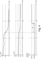
Figure 4 illustrates the temporal evolution of some quantities of the stack ofFigure 2 in case of thermal runaway of an electrochemical cell. - In
Figure 1 ,reference numeral 1 indicates, as a whole, an automotive electric battery (i.e. destined to be installed on board a vehicle). - The
battery 1 comprises a plurality of stacks (assemblies) 2 of lithium-ion electrochemical cells 3 (illustrated inFigure 2 ) electrically connected to one another; thestacks 2 are all identical to one another, i.e. are all formed by the same number and by the same type ofelectrochemical cells 3 connected in series. In the embodiment illustrated inFigure 1 , thebattery 1 comprises sevenstacks 2 all electrically connected to one another in series, but the number ofstacks 2 could be different and thestacks 2 could all be electrically connected to one another in parallel or they could be electrically connected to one another in part in series and in part in parallel. - According to what is illustrated in
Figure 2 , each stack 2 (assembly) comprises a plurality of lithium-ionelectrochemical cells 3 which are connected to one another in series and are arranged in asingle container 4 from which twoterminals 5 of thestack 2 come out. In the embodiment illustrated inFigure 2 , eachstack 2 comprises twelve lithium-ionelectrochemical cells 3 which are connected to one another in series, but the number ofelectrochemical cells 3 could be different. - Each
stack 2 comprises a plurality ofmeasuring instruments 6 which are configured to measure the electric voltage Vcell-i at the ends of eachelectrochemical cell 3 and are part of the so-called "BMU" ("Battery Management Unit", sometimes also called "Battery Management System") which is a control unit that monitors the state of the lithium-ionelectrochemical cells 3 based on their voltage; in particular, the "BMU" manages eachstack 2 of lithium-ionelectrochemical cells 3 defining a safe operating area (thanks to a careful balancing of the electric voltages between the electrochemical cells 3), i.e. a safety area inside which thestack 2 ensures the best technical and energy performance. - Furthermore, each
stack 2 comprises ameasuring instrument 7 which is still part of the "BMU" and is configured to measure the electric voltage Vstack at the ends of theentire stack 2 of electrochemical cells 3 (i.e. between theterminals 5 of the stack 2) which is given by the sum of the electric voltages Vcell-i of all theelectrochemical cells 3 which compose thestack 2 and are connected to one another in series. - The
battery 1 comprises acontrol unit 8 which is single and common to all thestacks 2 and reads the measurements carried out by themeasuring instruments stacks 2. - According to what is schematised in the flow diagram of
Figure 3 , thecontrol unit 8 is configured to diagnose the onset of a possible thermal runaway of anelectrochemical cell 3 by combining the electric information (the electric voltages Vcell-i and Vstack) provided by themeasuring instruments - In particular, the
control unit 8 cyclically verifies the electric voltage Vcell-i of eachelectrochemical cell 3 of eachstack 2 by comparing the electric voltage Vcell-i of theelectrochemical cell 3 with a threshold value TH1: if the electric voltage Vcell-i of anelectrochemical cell 3 is smaller than the threshold value TH1, then thecontrol unit 8 diagnoses a possible (not yet certain, since not yet confirmed by the following verifications described in the following) thermal runaway of theelectrochemical cell 3. - In order to confirm a possible (potential) thermal runaway of an
electrochemical cell 3, thecontrol unit 8 compares the electric voltage Vstack at the ends of theentire stack 2 of electrochemical cells 3 (in which theelectrochemical cell 3 potentially in thermal runaway is found) measured by themeasuring instrument 7 with the sum of the electric voltages Vcell-i of all theelectrochemical cells 3 which compose thestack 2 measured by the measuring instruments 6: if the difference (in absolute value) between the electric voltage Vstack at the ends of theentire stack 2 ofelectrochemical cells 3 and the sum of the electric voltages Vcell-i of all theelectrochemical cells 3 which compose thestack 2 is greater than a threshold value TH2, then thecontrol unit 8 diagnoses the breakage (malfunction) of one of themeasuring instruments 6 but does not diagnose a possible thermal runaway in theelectrochemical cells 3. - Obviously, also the breakage (malfunction) of one of the
measuring instruments 6 prevents the correct operation of theelectric battery 1 and thus it must be promptly reported and managed, but it does not cause (unlike a thermal runaway in the electrochemical cells 3) an immediate danger for the passengers of the vehicle in which theelectric battery 1 is installed. - Whereas, if the difference (in absolute value) between the electric voltage Vstack at the ends of the
entire stack 2 ofelectrochemical cells 3 and the sum of the electric voltages Vcell-i of all theelectrochemical cells 3 which compose thestack 2 is smaller than the threshold value TH2, then thecontrol unit 8 diagnoses a potential thermal runaway in the electrochemical cells 3 (not yet certain, since not yet confirmed by a further following verification described in the following). - According to a preferred embodiment, before diagnosing a thermal runaway in an
electrochemical cell 3, thecontrol unit 8 carries out a further control after the comparison between the electric voltage Vstack at the ends of theentire stack 2 ofelectrochemical cells 3 and the sum of the electric voltages Vcell-i of all theelectrochemical cells 3 which compose thestack 2. In particular, thecontrol unit 8 determines the maximum electric voltage Vstackmax between the electric voltages Vstack of all thestacks 2 and determines the minimum electric voltage Vstackmin between the electric voltages Vstack of all thestacks 2; subsequently, thecontrol unit 8 compares the maximum electric voltage Vstackmax (between all the stacks 2) with the minimum electric voltage Vstackmin (between all the stacks 2) and only if their difference in absolute value is greater than a threshold value TH3, then thecontrol unit 8 diagnoses an actual thermal runaway in anelectrochemical cell 3. That is, if the difference (in absolute value) between the maximum electric voltage Vstackmax (between all the stacks 2) and the minimum electric voltage Vstackmin (between all the stacks 2) is smaller than the threshold value TH3, then thecontrol unit 8 does not diagnose a thermal runaway in anelectrochemical cell 3; whereas, only if the difference (in absolute value) between the maximum electric voltage Vstackmax (between all the stacks 2) and the minimum electric voltage Vstackmin (between all the stacks 2) is greater than the threshold value TH3, then thecontrol unit 8 diagnoses a thermal runaway in anelectrochemical cell 3. - Preferably, before "publishing" (i.e. making final by sending out the corresponding signalling and the corresponding recovery procedures) a thermal runaway in an
electrochemical cell 3, thecontrol unit 8 waits for a confirmation amount of time ΔT (in the order of 1-5 seconds) during which the electric anomalies have to remain present and steady (in this manner, it is prevented to mistakenly signal a thermal runaway in anelectrochemical cell 3 by effect of temporary disturbances in the voltage measurements). - An example of what described in the foregoing is shown in the graphs illustrated in
Figure 4 , which illustrate the temporal evolution of an electric voltage Vcell-i of anelectrochemical cell 3 measured by ameasuring instrument 6 which at a certain instant is smaller than the threshold value TH1, the temporal evolution of the electric voltage Vstack at the ends of theentire stack 2 ofelectrochemical cells 3 measured by themeasuring instrument 7, and the temporal evolution of the diagnosis of thermal runaway. Shown inFigure 4 is the effect of the confirmation amount of time ΔT which delays the "publication" of the diagnosis of thermal runaway with respect to the evidence deriving from the electric voltages Vstack and Vcell-i. - According to a different embodiment, before diagnosing the thermal runaway of an
electrochemical cell 3, no comparison is carried out between the maximum electric voltage Vstackmax (between all the stacks 2) and the minimum electric voltage Vstackmin (between all the stacks 2); i.e. the thermal runaway of anelectrochemical cell 3 is diagnosed only by comparing the electric voltage Vcell-i of theelectrochemical cell 3 with the threshold value TH1 and by subsequently comparing the electric voltage Vstack at the ends of theentire stack 2 of electrochemical cells 3 (in which theelectrochemical cell 3 potentially in thermal runaway is found) with the sum of the electric voltages Vcell-i of all theelectrochemical cells 3 which compose thestack 2. - According to a further embodiment not illustrated, the
battery 1 could comprise asingle stack 2; obviously, in this embodiment, before diagnosing the thermal runaway of anelectrochemical cell 3 it is not possible to proceed with the comparison between the maximum electric voltage Vstackmax (between all the stacks 2) and the minimum electric voltage Vstackmin (between all the stacks 2) since asingle stack 2 is present. - It is important to observe that the diagnosis of the possible onset of a thermal runaway in one of the
electrochemical cells 3 is made only and exclusively based on the electric voltages Vcell-i measured by themeasuring instruments 6 and on the electric voltages Vstack measured by themeasuring instruments 7 and thus without using any thermal information (i.e. without using any temperature measurement). - The embodiments described herein can be combined together without departing from the scope of protection of the present invention.
- The above-described diagnosis method has numerous advantages.
- Firstly, the above-described diagnosis method allows diagnosing in an effective manner (i.e. without false negatives) the possible onset of a thermal runaway in one of the
electrochemical cells 3; in fact, the above-described diagnosis method always allows recognising the possible onset of a thermal runaway in one of theelectrochemical cells 3 since a thermal runaway necessarily causes a collapse of the electric voltage Vcell-i of theelectrochemical cell 3 in which the thermal runaway occurs. - Furthermore, the above-described diagnosis method allows diagnosing in an efficient manner (i.e. without false positives) the possible onset of a thermal runaway in one of the
electrochemical cells 3; in fact, the above-described diagnosis method always allows distinguishing between a problem in the measuring instruments and an actual thermal runaway in one of theelectrochemical cells 3. - Finally, the above-described diagnosis method is easy and cost-effective to implement, since it uses information which is generally already available and does not require a significant calculation power.
-
- 1
- electric battery
- 2
- stack
- 3
- electrochemical cells
- 4
- container
- 5
- terminals
- 6
- measuring instruments
- 7
- measuring instruments
- 8
- control unit
- Vstack
- electric voltage
- Vcell-i
- electric voltage
- Vstackmax
- electric voltage
- Vstackmin
- electric voltage
- TH1
- threshold
- TH2
- threshold
- TH3
- threshold
- ΔT
- confirmation amount of time
Claims (9)
- A method for the diagnosis of thermal runaway in an electric battery (1) comprising at least one stack (2) of electrochemical cells (3) connected to one another in series; the diagnosis method comprises the steps of:measuring a first electric voltage (Vcell-i) at the ends of each electrochemical cell (3);measuring a second electric voltage (Vstack) at the ends of the entire stack (2) of electrochemical cells (3); anddiagnosing a thermal runaway of an electrochemical cell (3), if the first electric voltage (Vcell-i) of the electrochemical cell (3) is smaller than a first threshold value (TH1);the diagnosis method is characterized in that it comprises the further steps of:calculating a difference between the second electric voltage (Vstack) and the sum of all first electric voltages (Vcell-i);diagnosing a thermal runaway of an electrochemical cell (3), only if the difference between the second electric voltage (Vstack) and the sum of all first electric voltages (Vcell-i) is smaller than a second threshold value (TH2);measuring all second electric voltages (Vstack) at the ends of each stack of the plurality of stacks (2) of electrochemical cells (3), identical to one another, making up the electric battery (1);determining, among all second electric voltages (Vstack) at the ends of each stack of the plurality of stacks (2) of electrochemical cells (3), a maximum second electric voltage (Vstackmax) and a minimum second electric voltage (Vstackmin);calculating a difference between the maximum second electric voltage (Vstackmax) and the minimum second electric voltage (Vstackmin);diagnosing a thermal runaway of an electrochemical cell (3), only if the difference between the maximum second electric voltage (Vstackmax) and the minimum second electric voltage (Vstackmin) is greater than a third threshold value (TH3) .
- The diagnosis method according to claim 1 and comprising the further step of diagnosing an error in the measurement of the first electric voltages (Vcell-i), if the difference between the second electric voltage (Vstack) and the sum of all first electric voltages (Vcell-i) is greater than the second threshold value (TH2).
- The diagnosis method according to claim 1 or 2 and comprising the further step of waiting for a confirmation amount of time (ΔT), during which the difference between the second electric voltage (Vstack) and the sum of all first electric voltages (Vcell-i) has to steadily remain smaller than the second threshold value (TH2), before making the diagnosis of a thermal runaway of an electrochemical cell (3) final.
- The diagnosis method according to claim 1, 2 or 3 and comprising the further step of diagnosing an error in the measurement of the first electric voltages (Vcell-i), if the difference between the maximum second electric voltage (Vstackmax) and the minimum second electric voltage (Vstackmin) is smaller than the third threshold value (TH3).
- The diagnosis method according to one of the claims from 1 to 4 and comprising the further step of waiting for a confirmation amount of time (ΔT), during which the difference between the maximum second electric voltage (Vstackmax) and the minimum second electric voltage (Vstackmin) has to steadily remain smaller than the third threshold value (TH3), before making the diagnosis of a thermal runaway of an electrochemical cell (3) final.
- The diagnosis method according to one of the claims from 1 to 5 and comprising the further step of diagnosing a thermal runaway of an electrochemical cell (3) only based on the first electric voltages (Vcell-i) and on the second electric voltage (Vstack), hence without using any thermal information.
- An electric battery (1) comprising:at least one stack (2) of electrochemical cells (3) connected to one another in series;a first measuring instrument (6) for each electrochemical cell (3), which is configured to measure a first electric voltage (Vcell-i) at the ends of the electrochemical cell (3);a second measuring instrument (7), which is configured to measure a second electric voltage (Vstack) at the ends of the entire stack (2) of electrochemical cells (3); anda control unit (8), which is configured to diagnose a thermal runaway of an electrochemical cell (3), if the first electric voltage (Vcell-i) is smaller than a first threshold value (TH1);the electric battery (1) is characterized in that the control unit (8) is configured for the steps of:calculating a difference between the second electric voltage (Vstack) and the sum of all first electric voltages (Vcell-i); anddiagnosing a thermal runaway of an electrochemical cell (3), only if the difference between the second electric voltage (Vstack) and the sum of all first electric voltages (Vcell-i) is smaller than a second threshold value (TH2);measuring all second electric voltages (Vstack) at the ends of each stack of the plurality of stacks (2) of electrochemical cells (3), identical to one another, making up the electric battery (1);determining, among all second electric voltages (Vstack) at the ends of each stack of the plurality of stacks (2) of electrochemical cells (3), a maximum second electric voltage (Vstackmax) and a minimum second electric voltage (Vstackmin);calculating a difference between the maximum second electric voltage (Vstackmax) and the minimum second electric voltage (Vstackmin); anddiagnosing a thermal runaway of an electrochemical cell (3), only if the difference between the maximum second electric voltage (Vstackmax) and the minimum second electric voltage (Vstackmin) is greater than a third threshold value (TH3) .
- A method for the diagnosis of thermal runaway in an electric battery (1) comprising at least one stack (2) of electrochemical cells (3) connected to one another in series; the diagnosis method comprises the steps of:measuring a first electric voltage (Vcell-i) at the ends of each electrochemical cell (3);measuring a second electric voltage (Vstack) at the ends of the entire stack (2) of electrochemical cells (3); anddiagnosing a thermal runaway of an electrochemical cell (3), if the first electric voltage (Vcell-i) of the electrochemical cell (3) is smaller than a first threshold value (TH1);the diagnosis method is characterized in that it comprises the further steps of:calculating a difference between the second electric voltage (Vstack) and the sum of all first electric voltages (Vcell-i);diagnosing a thermal runaway of an electrochemical cell (3), only if the difference between the second electric voltage (Vstack) and the sum of all first electric voltages (Vcell-i) is smaller than a second threshold value (TH2).
- An electric battery (1) comprising:at least one stack (2) of electrochemical cells (3) connected to one another in series;a first measuring instrument (6) for each electrochemical cell (3), which is configured to measure a first electric voltage (Vcell-i) at the ends of the electrochemical cell (3);a second measuring instrument (7), which is configured to measure a second electric voltage (Vstack) at the ends of the entire stack (2) of electrochemical cells (3); anda control unit (8), which is configured to diagnose a thermal runaway of an electrochemical cell (3), if the first electric voltage (Vcell-i) is smaller than a first threshold value (TH1);the electric battery (1) is characterized in that the control unit (8) is configured for the steps of:calculating a difference between the second electric voltage (Vstack) and the sum of all first electric voltages (Vcell-i); anddiagnosing a thermal runaway of an electrochemical cell (3), only if the difference between the second electric voltage (Vstack) and the sum of all first electric voltages (Vcell-i) is smaller than a second threshold value (TH2).
Applications Claiming Priority (1)
| Application Number | Priority Date | Filing Date | Title |
|---|---|---|---|
| IT202100028814 | 2021-11-12 |
Publications (2)
| Publication Number | Publication Date |
|---|---|
| EP4180829A1 true EP4180829A1 (en) | 2023-05-17 |
| EP4180829B1 EP4180829B1 (en) | 2024-05-22 |
Family
ID=79830831
Family Applications (1)
| Application Number | Title | Priority Date | Filing Date |
|---|---|---|---|
| EP22206886.8A Active EP4180829B1 (en) | 2021-11-12 | 2022-11-11 | Method for the diagnosis of thermal runaway in an electric battery |
Country Status (4)
| Country | Link |
|---|---|
| US (1) | US12469892B2 (en) |
| EP (1) | EP4180829B1 (en) |
| JP (1) | JP2023072679A (en) |
| CN (1) | CN116125305A (en) |
Cited By (1)
| Publication number | Priority date | Publication date | Assignee | Title |
|---|---|---|---|---|
| IT202300024903A1 (en) | 2023-11-23 | 2025-05-23 | Ferrari Spa | THERMAL PROPAGATION MANAGEMENT SYSTEM IN AN ELECTRIC BATTERY |
Citations (4)
| Publication number | Priority date | Publication date | Assignee | Title |
|---|---|---|---|---|
| US20130119941A1 (en) * | 2010-03-23 | 2013-05-16 | A123 Systems, Inc. | System and Method for Assessing ADC Operation and Voltage of a Battery Pack |
| EP3143655A1 (en) * | 2014-05-14 | 2017-03-22 | Bayerische Motoren Werke Aktiengesellschaft | Battery module with a controllable external heat sink |
| CN111913114A (en) | 2020-07-23 | 2020-11-10 | 蜂巢能源科技有限公司 | Battery thermal runaway detection method and device, storage medium and electronic equipment |
| CN112564240A (en) | 2020-12-18 | 2021-03-26 | 长城汽车股份有限公司 | Battery control system, battery control method, storage medium, and vehicle |
Family Cites Families (3)
| Publication number | Priority date | Publication date | Assignee | Title |
|---|---|---|---|---|
| US6037778A (en) * | 1997-11-05 | 2000-03-14 | Stat Engineering Company, L.L.C. | Electronic battery testing device and method for testing batteries |
| US9847558B1 (en) * | 2013-10-11 | 2017-12-19 | Hrl Laboratories, Llc | Methods and apparatus for real-time characterization of batteries with a reference electrode |
| KR102332444B1 (en) * | 2019-12-23 | 2021-11-26 | 삼성에스디아이 주식회사 | Thermal runaway detection device, battery system and thermal runaway detection method thereof |
-
2022
- 2022-11-01 US US18/051,601 patent/US12469892B2/en active Active
- 2022-11-09 JP JP2022179186A patent/JP2023072679A/en active Pending
- 2022-11-11 CN CN202211411611.6A patent/CN116125305A/en active Pending
- 2022-11-11 EP EP22206886.8A patent/EP4180829B1/en active Active
Patent Citations (4)
| Publication number | Priority date | Publication date | Assignee | Title |
|---|---|---|---|---|
| US20130119941A1 (en) * | 2010-03-23 | 2013-05-16 | A123 Systems, Inc. | System and Method for Assessing ADC Operation and Voltage of a Battery Pack |
| EP3143655A1 (en) * | 2014-05-14 | 2017-03-22 | Bayerische Motoren Werke Aktiengesellschaft | Battery module with a controllable external heat sink |
| CN111913114A (en) | 2020-07-23 | 2020-11-10 | 蜂巢能源科技有限公司 | Battery thermal runaway detection method and device, storage medium and electronic equipment |
| CN112564240A (en) | 2020-12-18 | 2021-03-26 | 长城汽车股份有限公司 | Battery control system, battery control method, storage medium, and vehicle |
Non-Patent Citations (1)
| Title |
|---|
| LIAO ZHENGHAI ET AL: "A survey of methods for monitoring and detecting thermal runaway of lithium-ion batteries", JOURNAL OF POWER SOURCES, ELSEVIER, AMSTERDAM, NL, vol. 436, 20 July 2019 (2019-07-20), XP085761281, ISSN: 0378-7753, [retrieved on 20190720], DOI: 10.1016/J.JPOWSOUR.2019.226879 * |
Cited By (1)
| Publication number | Priority date | Publication date | Assignee | Title |
|---|---|---|---|---|
| IT202300024903A1 (en) | 2023-11-23 | 2025-05-23 | Ferrari Spa | THERMAL PROPAGATION MANAGEMENT SYSTEM IN AN ELECTRIC BATTERY |
Also Published As
| Publication number | Publication date |
|---|---|
| EP4180829B1 (en) | 2024-05-22 |
| CN116125305A (en) | 2023-05-16 |
| JP2023072679A (en) | 2023-05-24 |
| US20230155196A1 (en) | 2023-05-18 |
| US12469892B2 (en) | 2025-11-11 |
Similar Documents
| Publication | Publication Date | Title |
|---|---|---|
| KR102332444B1 (en) | Thermal runaway detection device, battery system and thermal runaway detection method thereof | |
| EP2171824B1 (en) | Method of deactivating faulty battery cells | |
| US8618775B2 (en) | Detection of over-current shorts in a battery pack using pattern recognition | |
| US20190379030A1 (en) | Battery system configured to detect abnormal battery system conditions and method of the same | |
| EP3882944B1 (en) | Pyro igniter circuit and testing method | |
| EP3840083B1 (en) | Thermal runaway detection system and battery system | |
| US9520621B2 (en) | Method for detecting a triggering of a security device | |
| KR102738646B1 (en) | Apparatus For Fire Detection of Vehicle Battery and Method Thereof | |
| US20180340980A1 (en) | Method for checking a battery state and checking apparatus for checking a battery state | |
| KR102905953B1 (en) | Battery monitoring unit | |
| EP4180829B1 (en) | Method for the diagnosis of thermal runaway in an electric battery | |
| US20210184282A1 (en) | Method for diagnosis of a temperature control means of a battery pack | |
| Marcos et al. | A safety concept for an automotive lithium-based battery management system | |
| KR20150133065A (en) | Apparatus and method for determining reference voltage of detecting overcharge of battery | |
| CN115516324B (en) | Thermal diffusion determination method and thermal diffusion detection system of battery pack | |
| US20250055115A1 (en) | Battery system with impact detection | |
| US12438200B2 (en) | Battery cell and battery system including the same | |
| KR102923048B1 (en) | Apparatus of detecting thermal runaway for electric vehicle and method thereof | |
| KR20240149239A (en) | Fire monitoring system of vehicle carrier and method thereof | |
| EP4507064B1 (en) | Battery system for an electric vehicle and method for determination of a thermal runaway | |
| US20250023130A1 (en) | Battery arrangement, motor vehicle and method for detecting a gas discharge from a battery cell | |
| EP4407833A1 (en) | A protective circuit for a battery pack | |
| EP4559718A1 (en) | Method for detecting and evaluating a mechanical impact on a battery pack in an at least partially electric vehicle | |
| US20260100431A1 (en) | Systems and methods for detecting thermal runaway | |
| KR102960083B1 (en) | Battery module fault temperature sensor identification system and method |
Legal Events
| Date | Code | Title | Description |
|---|---|---|---|
| PUAI | Public reference made under article 153(3) epc to a published international application that has entered the european phase |
Free format text: ORIGINAL CODE: 0009012 |
|
| STAA | Information on the status of an ep patent application or granted ep patent |
Free format text: STATUS: THE APPLICATION HAS BEEN PUBLISHED |
|
| AK | Designated contracting states |
Kind code of ref document: A1 Designated state(s): AL AT BE BG CH CY CZ DE DK EE ES FI FR GB GR HR HU IE IS IT LI LT LU LV MC ME MK MT NL NO PL PT RO RS SE SI SK SM TR |
|
| STAA | Information on the status of an ep patent application or granted ep patent |
Free format text: STATUS: REQUEST FOR EXAMINATION WAS MADE |
|
| GRAP | Despatch of communication of intention to grant a patent |
Free format text: ORIGINAL CODE: EPIDOSNIGR1 |
|
| STAA | Information on the status of an ep patent application or granted ep patent |
Free format text: STATUS: GRANT OF PATENT IS INTENDED |
|
| 17P | Request for examination filed |
Effective date: 20231117 |
|
| RBV | Designated contracting states (corrected) |
Designated state(s): AL AT BE BG CH CY CZ DE DK EE ES FI FR GB GR HR HU IE IS IT LI LT LU LV MC ME MK MT NL NO PL PT RO RS SE SI SK SM TR |
|
| INTG | Intention to grant announced |
Effective date: 20231219 |
|
| GRAS | Grant fee paid |
Free format text: ORIGINAL CODE: EPIDOSNIGR3 |
|
| GRAA | (expected) grant |
Free format text: ORIGINAL CODE: 0009210 |
|
| STAA | Information on the status of an ep patent application or granted ep patent |
Free format text: STATUS: THE PATENT HAS BEEN GRANTED |
|
| AK | Designated contracting states |
Kind code of ref document: B1 Designated state(s): AL AT BE BG CH CY CZ DE DK EE ES FI FR GB GR HR HU IE IS IT LI LT LU LV MC ME MK MT NL NO PL PT RO RS SE SI SK SM TR |
|
| REG | Reference to a national code |
Ref country code: GB Ref legal event code: FG4D |
|
| REG | Reference to a national code |
Ref country code: CH Ref legal event code: EP |
|
| REG | Reference to a national code |
Ref country code: DE Ref legal event code: R096 Ref document number: 602022003591 Country of ref document: DE |
|
| REG | Reference to a national code |
Ref country code: IE Ref legal event code: FG4D |
|
| REG | Reference to a national code |
Ref country code: LT Ref legal event code: MG9D |
|
| REG | Reference to a national code |
Ref country code: NL Ref legal event code: MP Effective date: 20240522 |
|
| PG25 | Lapsed in a contracting state [announced via postgrant information from national office to epo] |
Ref country code: IS Free format text: LAPSE BECAUSE OF FAILURE TO SUBMIT A TRANSLATION OF THE DESCRIPTION OR TO PAY THE FEE WITHIN THE PRESCRIBED TIME-LIMIT Effective date: 20240922 |
|
| PG25 | Lapsed in a contracting state [announced via postgrant information from national office to epo] |
Ref country code: BG Free format text: LAPSE BECAUSE OF FAILURE TO SUBMIT A TRANSLATION OF THE DESCRIPTION OR TO PAY THE FEE WITHIN THE PRESCRIBED TIME-LIMIT Effective date: 20240522 |
|
| PG25 | Lapsed in a contracting state [announced via postgrant information from national office to epo] |
Ref country code: HR Free format text: LAPSE BECAUSE OF FAILURE TO SUBMIT A TRANSLATION OF THE DESCRIPTION OR TO PAY THE FEE WITHIN THE PRESCRIBED TIME-LIMIT Effective date: 20240522 Ref country code: FI Free format text: LAPSE BECAUSE OF FAILURE TO SUBMIT A TRANSLATION OF THE DESCRIPTION OR TO PAY THE FEE WITHIN THE PRESCRIBED TIME-LIMIT Effective date: 20240522 |
|
| PG25 | Lapsed in a contracting state [announced via postgrant information from national office to epo] |
Ref country code: GR Free format text: LAPSE BECAUSE OF FAILURE TO SUBMIT A TRANSLATION OF THE DESCRIPTION OR TO PAY THE FEE WITHIN THE PRESCRIBED TIME-LIMIT Effective date: 20240823 |
|
| PG25 | Lapsed in a contracting state [announced via postgrant information from national office to epo] |
Ref country code: PT Free format text: LAPSE BECAUSE OF FAILURE TO SUBMIT A TRANSLATION OF THE DESCRIPTION OR TO PAY THE FEE WITHIN THE PRESCRIBED TIME-LIMIT Effective date: 20240923 |
|
| REG | Reference to a national code |
Ref country code: AT Ref legal event code: MK05 Ref document number: 1689191 Country of ref document: AT Kind code of ref document: T Effective date: 20240522 |
|
| PG25 | Lapsed in a contracting state [announced via postgrant information from national office to epo] |
Ref country code: NL Free format text: LAPSE BECAUSE OF FAILURE TO SUBMIT A TRANSLATION OF THE DESCRIPTION OR TO PAY THE FEE WITHIN THE PRESCRIBED TIME-LIMIT Effective date: 20240522 |
|
| PG25 | Lapsed in a contracting state [announced via postgrant information from national office to epo] |
Ref country code: ES Free format text: LAPSE BECAUSE OF FAILURE TO SUBMIT A TRANSLATION OF THE DESCRIPTION OR TO PAY THE FEE WITHIN THE PRESCRIBED TIME-LIMIT Effective date: 20240522 |
|
| PG25 | Lapsed in a contracting state [announced via postgrant information from national office to epo] |
Ref country code: AT Free format text: LAPSE BECAUSE OF FAILURE TO SUBMIT A TRANSLATION OF THE DESCRIPTION OR TO PAY THE FEE WITHIN THE PRESCRIBED TIME-LIMIT Effective date: 20240522 |
|
| PG25 | Lapsed in a contracting state [announced via postgrant information from national office to epo] |
Ref country code: PL Free format text: LAPSE BECAUSE OF FAILURE TO SUBMIT A TRANSLATION OF THE DESCRIPTION OR TO PAY THE FEE WITHIN THE PRESCRIBED TIME-LIMIT Effective date: 20240522 |
|
| PG25 | Lapsed in a contracting state [announced via postgrant information from national office to epo] |
Ref country code: LV Free format text: LAPSE BECAUSE OF FAILURE TO SUBMIT A TRANSLATION OF THE DESCRIPTION OR TO PAY THE FEE WITHIN THE PRESCRIBED TIME-LIMIT Effective date: 20240522 |
|
| PG25 | Lapsed in a contracting state [announced via postgrant information from national office to epo] |
Ref country code: PT Free format text: LAPSE BECAUSE OF FAILURE TO SUBMIT A TRANSLATION OF THE DESCRIPTION OR TO PAY THE FEE WITHIN THE PRESCRIBED TIME-LIMIT Effective date: 20240923 Ref country code: PL Free format text: LAPSE BECAUSE OF FAILURE TO SUBMIT A TRANSLATION OF THE DESCRIPTION OR TO PAY THE FEE WITHIN THE PRESCRIBED TIME-LIMIT Effective date: 20240522 Ref country code: NO Free format text: LAPSE BECAUSE OF FAILURE TO SUBMIT A TRANSLATION OF THE DESCRIPTION OR TO PAY THE FEE WITHIN THE PRESCRIBED TIME-LIMIT Effective date: 20240822 Ref country code: NL Free format text: LAPSE BECAUSE OF FAILURE TO SUBMIT A TRANSLATION OF THE DESCRIPTION OR TO PAY THE FEE WITHIN THE PRESCRIBED TIME-LIMIT Effective date: 20240522 Ref country code: LV Free format text: LAPSE BECAUSE OF FAILURE TO SUBMIT A TRANSLATION OF THE DESCRIPTION OR TO PAY THE FEE WITHIN THE PRESCRIBED TIME-LIMIT Effective date: 20240522 Ref country code: IS Free format text: LAPSE BECAUSE OF FAILURE TO SUBMIT A TRANSLATION OF THE DESCRIPTION OR TO PAY THE FEE WITHIN THE PRESCRIBED TIME-LIMIT Effective date: 20240922 Ref country code: HR Free format text: LAPSE BECAUSE OF FAILURE TO SUBMIT A TRANSLATION OF THE DESCRIPTION OR TO PAY THE FEE WITHIN THE PRESCRIBED TIME-LIMIT Effective date: 20240522 Ref country code: GR Free format text: LAPSE BECAUSE OF FAILURE TO SUBMIT A TRANSLATION OF THE DESCRIPTION OR TO PAY THE FEE WITHIN THE PRESCRIBED TIME-LIMIT Effective date: 20240823 Ref country code: FI Free format text: LAPSE BECAUSE OF FAILURE TO SUBMIT A TRANSLATION OF THE DESCRIPTION OR TO PAY THE FEE WITHIN THE PRESCRIBED TIME-LIMIT Effective date: 20240522 Ref country code: ES Free format text: LAPSE BECAUSE OF FAILURE TO SUBMIT A TRANSLATION OF THE DESCRIPTION OR TO PAY THE FEE WITHIN THE PRESCRIBED TIME-LIMIT Effective date: 20240522 Ref country code: BG Free format text: LAPSE BECAUSE OF FAILURE TO SUBMIT A TRANSLATION OF THE DESCRIPTION OR TO PAY THE FEE WITHIN THE PRESCRIBED TIME-LIMIT Effective date: 20240522 Ref country code: AT Free format text: LAPSE BECAUSE OF FAILURE TO SUBMIT A TRANSLATION OF THE DESCRIPTION OR TO PAY THE FEE WITHIN THE PRESCRIBED TIME-LIMIT Effective date: 20240522 Ref country code: RS Free format text: LAPSE BECAUSE OF FAILURE TO SUBMIT A TRANSLATION OF THE DESCRIPTION OR TO PAY THE FEE WITHIN THE PRESCRIBED TIME-LIMIT Effective date: 20240822 |
|
| PG25 | Lapsed in a contracting state [announced via postgrant information from national office to epo] |
Ref country code: DK Free format text: LAPSE BECAUSE OF FAILURE TO SUBMIT A TRANSLATION OF THE DESCRIPTION OR TO PAY THE FEE WITHIN THE PRESCRIBED TIME-LIMIT Effective date: 20240522 |
|
| PG25 | Lapsed in a contracting state [announced via postgrant information from national office to epo] |
Ref country code: EE Free format text: LAPSE BECAUSE OF FAILURE TO SUBMIT A TRANSLATION OF THE DESCRIPTION OR TO PAY THE FEE WITHIN THE PRESCRIBED TIME-LIMIT Effective date: 20240522 |
|
| PG25 | Lapsed in a contracting state [announced via postgrant information from national office to epo] |
Ref country code: CZ Free format text: LAPSE BECAUSE OF FAILURE TO SUBMIT A TRANSLATION OF THE DESCRIPTION OR TO PAY THE FEE WITHIN THE PRESCRIBED TIME-LIMIT Effective date: 20240522 |
|
| PG25 | Lapsed in a contracting state [announced via postgrant information from national office to epo] |
Ref country code: RO Free format text: LAPSE BECAUSE OF FAILURE TO SUBMIT A TRANSLATION OF THE DESCRIPTION OR TO PAY THE FEE WITHIN THE PRESCRIBED TIME-LIMIT Effective date: 20240522 Ref country code: SK Free format text: LAPSE BECAUSE OF FAILURE TO SUBMIT A TRANSLATION OF THE DESCRIPTION OR TO PAY THE FEE WITHIN THE PRESCRIBED TIME-LIMIT Effective date: 20240522 |
|
| PG25 | Lapsed in a contracting state [announced via postgrant information from national office to epo] |
Ref country code: SK Free format text: LAPSE BECAUSE OF FAILURE TO SUBMIT A TRANSLATION OF THE DESCRIPTION OR TO PAY THE FEE WITHIN THE PRESCRIBED TIME-LIMIT Effective date: 20240522 Ref country code: RO Free format text: LAPSE BECAUSE OF FAILURE TO SUBMIT A TRANSLATION OF THE DESCRIPTION OR TO PAY THE FEE WITHIN THE PRESCRIBED TIME-LIMIT Effective date: 20240522 Ref country code: EE Free format text: LAPSE BECAUSE OF FAILURE TO SUBMIT A TRANSLATION OF THE DESCRIPTION OR TO PAY THE FEE WITHIN THE PRESCRIBED TIME-LIMIT Effective date: 20240522 Ref country code: DK Free format text: LAPSE BECAUSE OF FAILURE TO SUBMIT A TRANSLATION OF THE DESCRIPTION OR TO PAY THE FEE WITHIN THE PRESCRIBED TIME-LIMIT Effective date: 20240522 Ref country code: CZ Free format text: LAPSE BECAUSE OF FAILURE TO SUBMIT A TRANSLATION OF THE DESCRIPTION OR TO PAY THE FEE WITHIN THE PRESCRIBED TIME-LIMIT Effective date: 20240522 |
|
| REG | Reference to a national code |
Ref country code: DE Ref legal event code: R097 Ref document number: 602022003591 Country of ref document: DE |
|
| PLBE | No opposition filed within time limit |
Free format text: ORIGINAL CODE: 0009261 |
|
| STAA | Information on the status of an ep patent application or granted ep patent |
Free format text: STATUS: NO OPPOSITION FILED WITHIN TIME LIMIT |
|
| PG25 | Lapsed in a contracting state [announced via postgrant information from national office to epo] |
Ref country code: SI Free format text: LAPSE BECAUSE OF FAILURE TO SUBMIT A TRANSLATION OF THE DESCRIPTION OR TO PAY THE FEE WITHIN THE PRESCRIBED TIME-LIMIT Effective date: 20240522 |
|
| 26N | No opposition filed |
Effective date: 20250225 |
|
| PG25 | Lapsed in a contracting state [announced via postgrant information from national office to epo] |
Ref country code: MC Free format text: LAPSE BECAUSE OF FAILURE TO SUBMIT A TRANSLATION OF THE DESCRIPTION OR TO PAY THE FEE WITHIN THE PRESCRIBED TIME-LIMIT Effective date: 20240522 |
|
| PG25 | Lapsed in a contracting state [announced via postgrant information from national office to epo] |
Ref country code: LU Free format text: LAPSE BECAUSE OF NON-PAYMENT OF DUE FEES Effective date: 20241111 |
|
| REG | Reference to a national code |
Ref country code: BE Ref legal event code: MM Effective date: 20241130 |
|
| PG25 | Lapsed in a contracting state [announced via postgrant information from national office to epo] |
Ref country code: SE Free format text: LAPSE BECAUSE OF FAILURE TO SUBMIT A TRANSLATION OF THE DESCRIPTION OR TO PAY THE FEE WITHIN THE PRESCRIBED TIME-LIMIT Effective date: 20240522 |
|
| PG25 | Lapsed in a contracting state [announced via postgrant information from national office to epo] |
Ref country code: BE Free format text: LAPSE BECAUSE OF NON-PAYMENT OF DUE FEES Effective date: 20241130 |
|
| PG25 | Lapsed in a contracting state [announced via postgrant information from national office to epo] |
Ref country code: IE Free format text: LAPSE BECAUSE OF NON-PAYMENT OF DUE FEES Effective date: 20241111 |
|
| PGFP | Annual fee paid to national office [announced via postgrant information from national office to epo] |
Ref country code: DE Payment date: 20251126 Year of fee payment: 4 |
|
| PGFP | Annual fee paid to national office [announced via postgrant information from national office to epo] |
Ref country code: IT Payment date: 20251201 Year of fee payment: 4 |
|
| PGFP | Annual fee paid to national office [announced via postgrant information from national office to epo] |
Ref country code: FR Payment date: 20251124 Year of fee payment: 4 |
|
| PG25 | Lapsed in a contracting state [announced via postgrant information from national office to epo] |
Ref country code: HU Free format text: LAPSE BECAUSE OF FAILURE TO SUBMIT A TRANSLATION OF THE DESCRIPTION OR TO PAY THE FEE WITHIN THE PRESCRIBED TIME-LIMIT; INVALID AB INITIO Effective date: 20221111 |
|
| PG25 | Lapsed in a contracting state [announced via postgrant information from national office to epo] |
Ref country code: CY Free format text: LAPSE BECAUSE OF FAILURE TO SUBMIT A TRANSLATION OF THE DESCRIPTION OR TO PAY THE FEE WITHIN THE PRESCRIBED TIME-LIMIT; INVALID AB INITIO Effective date: 20221111 |
|
| PG25 | Lapsed in a contracting state [announced via postgrant information from national office to epo] |
Ref country code: SM Free format text: LAPSE BECAUSE OF FAILURE TO SUBMIT A TRANSLATION OF THE DESCRIPTION OR TO PAY THE FEE WITHIN THE PRESCRIBED TIME-LIMIT; INVALID AB INITIO Effective date: 20221111 |