EP4180730B1 - Air passage device, sterilization system, and ducting system - Google Patents
Air passage device, sterilization system, and ducting system Download PDFInfo
- Publication number
- EP4180730B1 EP4180730B1 EP22206128.5A EP22206128A EP4180730B1 EP 4180730 B1 EP4180730 B1 EP 4180730B1 EP 22206128 A EP22206128 A EP 22206128A EP 4180730 B1 EP4180730 B1 EP 4180730B1
- Authority
- EP
- European Patent Office
- Prior art keywords
- air passage
- passage device
- grid element
- air
- thickness
- Prior art date
- Legal status (The legal status is an assumption and is not a legal conclusion. Google has not performed a legal analysis and makes no representation as to the accuracy of the status listed.)
- Active
Links
Images



Classifications
-
- F—MECHANICAL ENGINEERING; LIGHTING; HEATING; WEAPONS; BLASTING
- F24—HEATING; RANGES; VENTILATING
- F24F—AIR-CONDITIONING; AIR-HUMIDIFICATION; VENTILATION; USE OF AIR CURRENTS FOR SCREENING
- F24F13/00—Details common to, or for air-conditioning, air-humidification, ventilation or use of air currents for screening
- F24F13/02—Ducting arrangements
-
- A—HUMAN NECESSITIES
- A61—MEDICAL OR VETERINARY SCIENCE; HYGIENE
- A61L—METHODS OR APPARATUS FOR STERILISING MATERIALS OR OBJECTS IN GENERAL; DISINFECTION, STERILISATION OR DEODORISATION OF AIR; CHEMICAL ASPECTS OF BANDAGES, DRESSINGS, ABSORBENT PADS OR SURGICAL ARTICLES; MATERIALS FOR BANDAGES, DRESSINGS, ABSORBENT PADS OR SURGICAL ARTICLES
- A61L9/00—Disinfection, sterilisation or deodorisation of air
- A61L9/16—Disinfection, sterilisation or deodorisation of air using physical phenomena
- A61L9/18—Radiation
- A61L9/20—Ultraviolet radiation
-
- B—PERFORMING OPERATIONS; TRANSPORTING
- B01—PHYSICAL OR CHEMICAL PROCESSES OR APPARATUS IN GENERAL
- B01D—SEPARATION
- B01D53/00—Separation of gases or vapours; Recovering vapours of volatile solvents from gases; Chemical or biological purification of waste gases, e.g. engine exhaust gases, smoke, fumes, flue gases, aerosols
- B01D53/007—Separation of gases or vapours; Recovering vapours of volatile solvents from gases; Chemical or biological purification of waste gases, e.g. engine exhaust gases, smoke, fumes, flue gases, aerosols by irradiation
-
- B—PERFORMING OPERATIONS; TRANSPORTING
- B01—PHYSICAL OR CHEMICAL PROCESSES OR APPARATUS IN GENERAL
- B01D—SEPARATION
- B01D53/00—Separation of gases or vapours; Recovering vapours of volatile solvents from gases; Chemical or biological purification of waste gases, e.g. engine exhaust gases, smoke, fumes, flue gases, aerosols
- B01D53/34—Chemical or biological purification of waste gases
- B01D53/38—Removing components of undefined structure
- B01D53/44—Organic components
-
- F—MECHANICAL ENGINEERING; LIGHTING; HEATING; WEAPONS; BLASTING
- F24—HEATING; RANGES; VENTILATING
- F24F—AIR-CONDITIONING; AIR-HUMIDIFICATION; VENTILATION; USE OF AIR CURRENTS FOR SCREENING
- F24F13/00—Details common to, or for air-conditioning, air-humidification, ventilation or use of air currents for screening
- F24F13/02—Ducting arrangements
- F24F13/06—Outlets for directing or distributing air into rooms or spaces, e.g. ceiling air diffuser
-
- F—MECHANICAL ENGINEERING; LIGHTING; HEATING; WEAPONS; BLASTING
- F24—HEATING; RANGES; VENTILATING
- F24F—AIR-CONDITIONING; AIR-HUMIDIFICATION; VENTILATION; USE OF AIR CURRENTS FOR SCREENING
- F24F13/00—Details common to, or for air-conditioning, air-humidification, ventilation or use of air currents for screening
- F24F13/08—Air-flow control members, e.g. louvres, grilles, flaps or guide plates
- F24F13/082—Grilles, registers or guards
- F24F13/084—Grilles, registers or guards with mounting arrangements, e.g. snap fasteners for mounting to the wall or duct
-
- F—MECHANICAL ENGINEERING; LIGHTING; HEATING; WEAPONS; BLASTING
- F24—HEATING; RANGES; VENTILATING
- F24F—AIR-CONDITIONING; AIR-HUMIDIFICATION; VENTILATION; USE OF AIR CURRENTS FOR SCREENING
- F24F7/00—Ventilation
- F24F7/003—Ventilation in combination with air cleaning
-
- F—MECHANICAL ENGINEERING; LIGHTING; HEATING; WEAPONS; BLASTING
- F24—HEATING; RANGES; VENTILATING
- F24F—AIR-CONDITIONING; AIR-HUMIDIFICATION; VENTILATION; USE OF AIR CURRENTS FOR SCREENING
- F24F7/00—Ventilation
- F24F7/04—Ventilation with ducting systems, e.g. by double walls; with natural circulation
- F24F7/06—Ventilation with ducting systems, e.g. by double walls; with natural circulation with forced air circulation, e.g. by fan positioning of a ventilator in or against a conduit
- F24F7/065—Ventilation with ducting systems, e.g. by double walls; with natural circulation with forced air circulation, e.g. by fan positioning of a ventilator in or against a conduit fan combined with single duct; mounting arrangements of a fan in a duct
-
- F—MECHANICAL ENGINEERING; LIGHTING; HEATING; WEAPONS; BLASTING
- F24—HEATING; RANGES; VENTILATING
- F24F—AIR-CONDITIONING; AIR-HUMIDIFICATION; VENTILATION; USE OF AIR CURRENTS FOR SCREENING
- F24F8/00—Treatment, e.g. purification, of air supplied to human living or working spaces otherwise than by heating, cooling, humidifying or drying
- F24F8/20—Treatment, e.g. purification, of air supplied to human living or working spaces otherwise than by heating, cooling, humidifying or drying by sterilisation
- F24F8/22—Treatment, e.g. purification, of air supplied to human living or working spaces otherwise than by heating, cooling, humidifying or drying by sterilisation using UV light
-
- A—HUMAN NECESSITIES
- A61—MEDICAL OR VETERINARY SCIENCE; HYGIENE
- A61L—METHODS OR APPARATUS FOR STERILISING MATERIALS OR OBJECTS IN GENERAL; DISINFECTION, STERILISATION OR DEODORISATION OF AIR; CHEMICAL ASPECTS OF BANDAGES, DRESSINGS, ABSORBENT PADS OR SURGICAL ARTICLES; MATERIALS FOR BANDAGES, DRESSINGS, ABSORBENT PADS OR SURGICAL ARTICLES
- A61L2209/00—Aspects relating to disinfection, sterilisation or deodorisation of air
- A61L2209/10—Apparatus features
- A61L2209/13—Dispensing or storing means for active compounds
- A61L2209/135—Vaporisers for active components
-
- A—HUMAN NECESSITIES
- A61—MEDICAL OR VETERINARY SCIENCE; HYGIENE
- A61L—METHODS OR APPARATUS FOR STERILISING MATERIALS OR OBJECTS IN GENERAL; DISINFECTION, STERILISATION OR DEODORISATION OF AIR; CHEMICAL ASPECTS OF BANDAGES, DRESSINGS, ABSORBENT PADS OR SURGICAL ARTICLES; MATERIALS FOR BANDAGES, DRESSINGS, ABSORBENT PADS OR SURGICAL ARTICLES
- A61L2209/00—Aspects relating to disinfection, sterilisation or deodorisation of air
- A61L2209/10—Apparatus features
- A61L2209/16—Connections to a HVAC unit
-
- B—PERFORMING OPERATIONS; TRANSPORTING
- B01—PHYSICAL OR CHEMICAL PROCESSES OR APPARATUS IN GENERAL
- B01D—SEPARATION
- B01D2257/00—Components to be removed
- B01D2257/91—Bacteria; Microorganisms
-
- B—PERFORMING OPERATIONS; TRANSPORTING
- B01—PHYSICAL OR CHEMICAL PROCESSES OR APPARATUS IN GENERAL
- B01D—SEPARATION
- B01D2258/00—Sources of waste gases
- B01D2258/06—Polluted air
-
- B—PERFORMING OPERATIONS; TRANSPORTING
- B01—PHYSICAL OR CHEMICAL PROCESSES OR APPARATUS IN GENERAL
- B01D—SEPARATION
- B01D2259/00—Type of treatment
- B01D2259/45—Gas separation or purification devices adapted for specific applications
- B01D2259/4508—Gas separation or purification devices adapted for specific applications for cleaning air in buildings
-
- B—PERFORMING OPERATIONS; TRANSPORTING
- B01—PHYSICAL OR CHEMICAL PROCESSES OR APPARATUS IN GENERAL
- B01D—SEPARATION
- B01D2259/00—Type of treatment
- B01D2259/80—Employing electric, magnetic, electromagnetic or wave energy, or particle radiation
- B01D2259/804—UV light
Definitions
- the present invention relates to an air passage device suitable for allowing the passage of air while preventing the passage of light, a sterilization system, and a ducting system.
- some closed environments need to be ventilated by preventing the entry of sunlight, such as darkrooms or special analysis laboratories, or greenhouses for growing certain plants.
- Document WO2016/178698A discloses an active oxidation and purifying system, provided to increase or maximize the rate of photocatalytic oxidation and ambient air purification capacity by implementing both direct ultraviolet (UV) light and reflected UV light directed to the surface and apertures of active cell panels coated with a photocatalytic material.
- UV direct ultraviolet
- a first set of the apertures could be disposed about 45 degrees relative to a median axis along the first and second surfaces, while a second set of apertures could be disposed about negative 45 degrees relative to the same median axis in order to increase the surface area impinged by the direct and reflected UV light.
- an air passage device for air ventilation in closed environments has been referred to collectively with reference number 1.
- the sterilization system 9 that comprises an air passage device 1 is also an object of the present invention.
- the air passage device comprises a first grid element 11 which extends mainly on a first imaginary plane A and which has a first thickness L1 along a first air passage direction Z-Z perpendicular to said first imaginary plane A.
- the first grid element 2 comprises a first grid body 110 in which first openings 51 are obtained, each extending respectively for the entire first thickness L1 with a first opening height H1, along first main opening axes C-C substantially parallel respectively to the first air passage direction Z-Z.
- said first openings 51 are delimited by first side walls 510 having a first diffusive reflecting inner surface 510'.
- the air passage device comprises a second grid element 12 which extends on a second imaginary plane B and which has a second thickness L2 along a second air passage direction Z'-Z' perpendicular to said second imaginary plane B.
- the second grid element 12 comprises a second grid body 120 in which second openings 52 are obtained, each extending respectively for the entire second thickness L2 with a second opening height H1, along second main opening axes C'-C' substantially parallel respectively to the second air passage direction Z'-Z'.
- said second openings 52 are delimited by second side walls 520 having a second diffusive reflecting inner surface 520'.
- first denotes features and components of the first grid element 11
- second denotes features and components of the second grid element 12. This distinction is only a convention and does not indicate differences in magnitude or flow.
- said first and second diffusive reflecting inner surfaces 510' and 520' are made of a material having a total reflectance coefficient lower than 0.5, preferably lower than 0.2 in the light ray spectrum of interest.
- Total reflectance is defined as the union of diffusive reflectance and specular reflectance.
- the air passage device further comprises a support frame 15 that supports and connects said first grid element 11 and said second grid element 12, so that the first grid element 11 and the second grid element 12 are crossed in series by air.
- the first imaginary plane A and the second imaginary plane B are mutually incident with an inclination angle ⁇ that is a function of said first and second thicknesses L1, L2 and of said first and second opening heights H1, H2, so that at least one portion of a light ray entering said openings 51, 52 is absorbed by the diffusive reflecting inner surface 510', 520' of at least one of said openings 51, 52.
- the inclination angle ⁇ is a function of said first and second thicknesses L1, L2 and of said first and second opening heights H1, H2 according to the formula: ⁇ ⁇ arctan H 1 / L 1 + arctan H 2 / L 2
- the inclination angle is greater than or equal to the sum of the arctangent of the ratio H1/L1 plus the arctangent of the ratio H2/L2.
- the air passage device comprises a minimum number of grid elements that is a function of the number of reflections of the light rays desired.
- the air passage device must comprise three grid elements mutually inclined at an inclination angle ⁇ .
- the first opening height H1 is less, preferably half, with respect to said first thickness L1 and the second opening height H2 is less, preferably half, with respect to said second thickness L2.
- the first opening height H1 is lower than half of said first thickness L1 and the second opening height H2 is lower than half of said second thickness L2.
- the first thickness L1 coincides with the second thickness L2.
- the air passage device 1 comprises an auxiliary grid element 16 arranged in series with said first grid element 11 and second grid element 12.
- the auxiliary grid element 16 also comprises a third grid body in which third openings are obtained.
- this auxiliary grid element 16 extends along a third imaginary plane D mutually incident with said first and second imaginary planes A, B.
- said third imaginary plane D forms, with the first imaginary plane A, a first auxiliary inclination angle ⁇ and forms, with the second imaginary plane B, a second auxiliary inclination angle ⁇ .
- said auxiliary grid element 16 is interposed between said first grid element 11 and said second grid element 12.
- the sum of these first and second auxiliary inclination angles ⁇ and ⁇ coincides with the inclination angle ⁇ .
- the first auxiliary inclination angle ⁇ and/or the second auxiliary inclination angle ⁇ coincides with the inclination angle ⁇ .
- the air passage device 1 comprises a plurality of auxiliary grid elements.
- the air passage device comprises a total number Ntot of grid elements (including said first and second grid elements and said auxiliary grid elements) at least greater than or equal to said minimum number of grid elements Nmin.
- an air passage device 1 comprising a total number Ntot of grid elements, at least a minimum number of grid elements Nmin, even if not adjacent, must be mutually inclined with said inclination angle ⁇ .
- the air passage device 1 comprises at least two grid elements inclined to each other by an inclination angle ⁇ that follows the formula described above.
- the additional grid elements 16 mutually form angles other than said inclination angle ⁇ .
- said first openings 51 and said second openings 52 have polygonal cross-sections.
- said first and second openings 51 and 52 have hexagonal cross-sections.
- the first diffusive reflecting inner surface 510' and the second diffusive reflecting inner surface 520' are made of a material that reflects the light rays diffusively in the spectrum of interest. In other words, they are made of a Lambertian-type material, having features of a non-ideal diffuser.
- a non-ideal diffuser means a material suitable for absorbing a portion of the incident ray, and reflecting the remaining portion diffusively.
- said first and second diffusive reflecting inner surfaces 510' and 520' are made of a material having a total reflectance coefficient (diffuse and specular) lower than 0.5, preferably lower than 0.2, in the visible spectrum.
- said first and second diffusive reflecting inner surfaces 510' and 520' are made of a material having a total reflectance coefficient (diffuse and specular) lower than 0.5, preferably lower than 0.2, in the UV spectrum.
- the air passage device also comprises a cover panel 125 applied externally to the first grid element 11.
- a window 130 is obtained in this cover panel 125, which window provides access to the first grid body 110 of said first grid element 11.
- this window 130 has a polygonal shape, for example, it is a rectangle, or it has an elliptical shape, or it is circular.
- the air passage device comprises a cover panel 125 also applied externally to the second grid element 12.
- the air passage device 1 comprises a fan 18 inside the first grid element 11, for the suction of the air passing through said first grid element 11.
- the fan 18 is inside the second grid element 12, for the purpose of suctioning the air passing through said second grid element 12.
- said fan 18 is positioned at said window 130.
- a sterilization system 9 for sterilizing air in a closed environment also forms an object of the present invention.
- the sterilization system 9 comprises:
- this sterilization system 9 comprises an air passage device 1 according to the invention also in proximity to the inlet mouth 910.
- This ducting system is suitable for allowing the ventilation of the closed environment by preventing the passage of light rays to or from said closed environment, preferably by preventing the entry of light rays from the ducting system.
- this closed environment is a dark environment, such as a darkroom.
- the air passage device, the sterilization system and the ducting system covered by the present invention largely fulfill the intended object, overcoming the typical problems of the prior art.
- the air passage device promotes air flow, minimizing the exit of light rays.
- the air passage device is easy to assemble and arrange.
- the air passage device may be easily adapted to any sterilization system or any pre-existing ducting system.
- the air passage device also does not require the use of filters.
- the air passage device does not force abrupt changes in flow, solving the problem of air pressure drops.
- the air passage device minimizes the turbulence, noise and air flow resistance caused when blocking the passage of light.
- the grid elements made of a material having a total reflectance coefficient lower than 0.5, preferably lower than 0.2, and preferably with the features of a non-ideal diffuser, allow for a good part of the reflected portion of the light ray to be absorbed with each reflection.
- using a fan positioned externally to the first or second grid element allows for increased airflow through the air passage device.
- the sterilization system according to the present invention effectively blocks the exit of UV rays from the irradiation chamber.
- the ducting system according to the present invention is effectively applicable to the walls of darkrooms or places that need to maintain a dark condition by blocking the entry of light but allowing the recirculation of air.
Landscapes
- Engineering & Computer Science (AREA)
- Chemical & Material Sciences (AREA)
- Combustion & Propulsion (AREA)
- Mechanical Engineering (AREA)
- General Engineering & Computer Science (AREA)
- Health & Medical Sciences (AREA)
- Oil, Petroleum & Natural Gas (AREA)
- Chemical Kinetics & Catalysis (AREA)
- General Chemical & Material Sciences (AREA)
- Analytical Chemistry (AREA)
- Public Health (AREA)
- Veterinary Medicine (AREA)
- Toxicology (AREA)
- General Health & Medical Sciences (AREA)
- Animal Behavior & Ethology (AREA)
- Epidemiology (AREA)
- Life Sciences & Earth Sciences (AREA)
- Biomedical Technology (AREA)
- Environmental & Geological Engineering (AREA)
- Disinfection, Sterilisation Or Deodorisation Of Air (AREA)
- Duct Arrangements (AREA)
Description
- The present invention relates to an air passage device suitable for allowing the passage of air while preventing the passage of light, a sterilization system, and a ducting system.
- In the prior art, there are situations where it is necessary to facilitate the passage of air without allowing the passage of light, from an outdoor environment to a closed environment, or vice versa, or between two closed environments.
- For example, some closed environments need to be ventilated by preventing the entry of sunlight, such as darkrooms or special analysis laboratories, or greenhouses for growing certain plants.
- Alternatively, in some situations it is necessary to shield light rays that are used for air treatment or therapy applications, so that they do not escape from the chamber in which they are emitted, while still allowing air exchange.
- Disadvantageously, the known solutions for this requirement have drawbacks.
- The most common solutions involve the use of a complex set of intricate channels and filters, so that light is absorbed through numerous reflections in said channels while at the same time allowing a portion of air to pass through. Document
WO2016/178698A discloses an active oxidation and purifying system, provided to increase or maximize the rate of photocatalytic oxidation and ambient air purification capacity by implementing both direct ultraviolet (UV) light and reflected UV light directed to the surface and apertures of active cell panels coated with a photocatalytic material. A first set of the apertures could be disposed about 45 degrees relative to a median axis along the first and second surfaces, while a second set of apertures could be disposed about negative 45 degrees relative to the same median axis in order to increase the surface area impinged by the direct and reflected UV light. - Disadvantageously, these solutions force the flow of air into the channels or through the filter fibers, changing its direction in a sudden and abrupt way. Because of these changes, turbulence and a multiplicity of boundary layers are generated in the airflow in the areas near the walls of channels or between the filter cavities. This turbulence leads to an amplification of noise in the ventilation process, as well as an increase in the resistance that air must overcome to pass through ventilation ducts.
- Furthermore, disadvantageously, these known solutions require the use of very powerful fans, and consequently result in an additional increase in power consumption.
- In other words, the known system solutions belonging to the prior art fail to effectively perform both functions: they either perform efficient air passage or efficient light blocking.
- In other words, some systems are very efficient in terms of ventilation but do not block all the light, while other systems block a large percentage of light rays but allow only a weakened airflow.
- Therefore, there appears to be a strong need to provide an air passage device that is able to overcome the aforementioned drawbacks of the prior art.
- This requirement is met by an air passage device defined in
claim 1. - The claims dependent thereon describe preferred or advantageous embodiments of the invention, comprising further advantageous features.
- The features and advantages of the air passage device, of a sterilization system and of a ducting system will become apparent from the following description of a number of preferred embodiments, given by way of non-limiting example, with reference to the attached figures, in which:
-
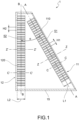
Fig. 1 is a sectional side view of an air passage device in accordance with a preferred embodiment according to the present invention; -
Fig. 2a and 2b are front views of two preferred alternative embodiments of the present invention; -
Fig. 3 is a sectional side view of an air passage device in accordance with a preferred embodiment, according to the present invention; -
Fig. 3b is a front view of the air passage device inFig. 3a ; -
Fig. 4 is a detailed side view of the grid elements of an air passage device in accordance with a preferred embodiment, according to the present invention; -
Fig. 5 is an axonometric view of a detail of a grid element of an air passage device in accordance with a preferred embodiment according to the present invention. -
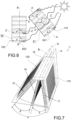
Fig. 6 is a schematic side view in which the path taken by light rays inside an air passage device is schematized in accordance with an embodiment according to the present invention; -
Fig. 7 shows a perspective view of an air passage device in accordance with an embodiment according to the present invention; -
Fig. 8 is a longitudinal section of a sterilization system in accordance with a preferred embodiment according to the present invention. - With reference to the aforesaid figures, an air passage device for air ventilation in closed environments has been referred to collectively with
reference number 1. - In the present discussion, speaking of "closed environments" refers to the rooms of a building, and also to the inner chambers, ducts, and compartments of a device or apparatus or system, such as the irradiation chamber of a sterilization system. For example, the
sterilization system 9 that comprises anair passage device 1 is also an object of the present invention. - According to the invention, the air passage device comprises a
first grid element 11 which extends mainly on a first imaginary plane A and which has a first thickness L1 along a first air passage direction Z-Z perpendicular to said first imaginary plane A. - Furthermore, the first grid element 2 comprises a
first grid body 110 in whichfirst openings 51 are obtained, each extending respectively for the entire first thickness L1 with a first opening height H1, along first main opening axes C-C substantially parallel respectively to the first air passage direction Z-Z. - Moreover, according to the present invention, said
first openings 51 are delimited byfirst side walls 510 having a first diffusive reflectinginner surface 510'. - According to the present invention, moreover, the air passage device comprises a
second grid element 12 which extends on a second imaginary plane B and which has a second thickness L2 along a second air passage direction Z'-Z' perpendicular to said second imaginary plane B. - Furthermore, the
second grid element 12 comprises asecond grid body 120 in whichsecond openings 52 are obtained, each extending respectively for the entire second thickness L2 with a second opening height H1, along second main opening axes C'-C' substantially parallel respectively to the second air passage direction Z'-Z'. - Moreover, according to the present invention, said
second openings 52 are delimited bysecond side walls 520 having a second diffusive reflecting inner surface 520'. - As just described in the aforesaid paragraphs, "first" denotes features and components of the
first grid element 11, and "second" denotes features and components of thesecond grid element 12. This distinction is only a convention and does not indicate differences in magnitude or flow. - Preferably, said first and second diffusive reflecting
inner surfaces 510' and 520' are made of a material having a total reflectance coefficient lower than 0.5, preferably lower than 0.2 in the light ray spectrum of interest. Total reflectance is defined as the union of diffusive reflectance and specular reflectance. - According to the invention, the air passage device further comprises a
support frame 15 that supports and connects saidfirst grid element 11 and saidsecond grid element 12, so that thefirst grid element 11 and thesecond grid element 12 are crossed in series by air. - Specifically, according to the invention, the first imaginary plane A and the second imaginary plane B are mutually incident with an inclination angle α that is a function of said first and second thicknesses L1, L2 and of said first and second opening heights H1, H2, so that at least one portion of a light ray entering said
openings inner surface 510', 520' of at least one of saidopenings - Preferably, the inclination angle α is a function of said first and second thicknesses L1, L2 and of said first and second opening heights H1, H2 according to the formula:

- In other words, the inclination angle is greater than or equal to the sum of the arctangent of the ratio H1/L1 plus the arctangent of the ratio H2/L2.
- According to a preferred embodiment, the air passage device comprises a minimum number of grid elements that is a function of the number of reflections of the light rays desired.
- In particular, preferably, the minimum number of grid elements varies according to the formula:

- In other words, for example, if at least two reflections are to be obtained, the air passage device must comprise three grid elements mutually inclined at an inclination angle α.
- It is clear that the inclination angle α is variable for each pair of mutually inclined grid elements, and varies with the geometry and dimensions of the respective grid elements.
- Preferably, moreover, the first opening height H1 is less, preferably half, with respect to said first thickness L1 and the second opening height H2 is less, preferably half, with respect to said second thickness L2.
- Even more preferably, the first opening height H1 is lower than half of said first thickness L1 and the second opening height H2 is lower than half of said second thickness L2.
- In an advantageous embodiment, the first thickness L1 coincides with the second thickness L2.
- In one embodiment of the invention, the
air passage device 1 comprises anauxiliary grid element 16 arranged in series with saidfirst grid element 11 andsecond grid element 12. - According to one embodiment of the invention, the
auxiliary grid element 16 also comprises a third grid body in which third openings are obtained. - Preferably, this
auxiliary grid element 16 extends along a third imaginary plane D mutually incident with said first and second imaginary planes A, B. - Preferably, moreover, said third imaginary plane D forms, with the first imaginary plane A, a first auxiliary inclination angle δ and forms, with the second imaginary plane B, a second auxiliary inclination angle β.
- Preferably, said
auxiliary grid element 16 is interposed between saidfirst grid element 11 and saidsecond grid element 12. - According to a preferred embodiment, with reference to an example embodiment depicted in
Fig. 7 , the sum of these first and second auxiliary inclination angles δ and β coincides with the inclination angle α. - In an alternative embodiment according to the present invention, the first auxiliary inclination angle δ and/or the second auxiliary inclination angle β coincides with the inclination angle α.
- Preferably, the
air passage device 1 comprises a plurality of auxiliary grid elements. - According to one embodiment, in accordance with the present invention, the air passage device comprises a total number Ntot of grid elements (including said first and second grid elements and said auxiliary grid elements) at least greater than or equal to said minimum number of grid elements Nmin.
- Preferably, in an
air passage device 1 comprising a total number Ntot of grid elements, at least a minimum number of grid elements Nmin, even if not adjacent, must be mutually inclined with said inclination angle α. - In other words, by way of example, in an air passage device comprising a total number of grid elements Ntot equal to five, and where the number of desired reflections Nref is equal to one, the minimum number of grid elements is equal to two. Therefore, preferably, the
air passage device 1 comprises at least two grid elements inclined to each other by an inclination angle α that follows the formula described above. - Preferably, the
additional grid elements 16 mutually form angles other than said inclination angle α. - According to a preferred embodiment, said
first openings 51 and saidsecond openings 52 have polygonal cross-sections. - Preferably, said first and
second openings - Even more preferably, the first diffusive reflecting
inner surface 510' and the second diffusive reflecting inner surface 520' are made of a material that reflects the light rays diffusively in the spectrum of interest. In other words, they are made of a Lambertian-type material, having features of a non-ideal diffuser. - It is specified that a non-ideal diffuser means a material suitable for absorbing a portion of the incident ray, and reflecting the remaining portion diffusively.
- In other words, if the light rays belong to the visible spectrum, said first and second diffusive reflecting
inner surfaces 510' and 520' are made of a material having a total reflectance coefficient (diffuse and specular) lower than 0.5, preferably lower than 0.2, in the visible spectrum. - Alternatively, if the light rays belong to the UV spectrum, said first and second diffusive reflecting
inner surfaces 510' and 520' are made of a material having a total reflectance coefficient (diffuse and specular) lower than 0.5, preferably lower than 0.2, in the UV spectrum. - In a variant embodiment, the air passage device also comprises a
cover panel 125 applied externally to thefirst grid element 11. - Preferably, with reference to some of the example embodiments depicted in
Fig. 2a, 2b ,3a and 3b , awindow 130 is obtained in thiscover panel 125, which window provides access to thefirst grid body 110 of saidfirst grid element 11. - According to a preferred embodiment, this
window 130 has a polygonal shape, for example, it is a rectangle, or it has an elliptical shape, or it is circular. - According to one embodiment, the air passage device comprises a
cover panel 125 also applied externally to thesecond grid element 12. - According to a variant embodiment, the
air passage device 1 comprises afan 18 inside thefirst grid element 11, for the suction of the air passing through saidfirst grid element 11. - According to a further variant embodiment, the
fan 18 is inside thesecond grid element 12, for the purpose of suctioning the air passing through saidsecond grid element 12. - Preferably, with reference to an example embodiment depicted in
Fig. 3a and 3b , saidfan 18 is positioned at saidwindow 130. - As mentioned above, a
sterilization system 9 for sterilizing air in a closed environment also forms an object of the present invention. - According to the present invention, the
sterilization system 9 comprises: - an
irradiation chamber 90 extending along an axis X-X, between anair inlet end 91 and anair outlet end 92, wherein saidirradiation chamber 90 is peripherally delimited by acasing 900 having a reflective casing inner surface; - an
inlet mouth 910 in proximity to saidair inlet end 91 and anoutlet mouth 920 in proximity to saidair outlet end 92; - an
emitter 95 suitable for emitting UV rays into theirradiation chamber 90; - an
air passage device 1 according to the present invention and as described. - Preferably, with reference to an example shown in
Fig. 8 , thissterilization system 9 comprises anair passage device 1 according to the invention also in proximity to theinlet mouth 910. - It is also a subject of the present invention to provide a ducting system for a closed environment, comprising an
air passage device 1 according to theclaims 1 to 7. - This ducting system is suitable for allowing the ventilation of the closed environment by preventing the passage of light rays to or from said closed environment, preferably by preventing the entry of light rays from the ducting system.
- Preferably, this closed environment is a dark environment, such as a darkroom.
- Innovatively, the air passage device, the sterilization system and the ducting system covered by the present invention largely fulfill the intended object, overcoming the typical problems of the prior art.
- Advantageously, the air passage device promotes air flow, minimizing the exit of light rays.
- Advantageously, the air passage device is easy to assemble and arrange.
- Advantageously, the air passage device may be easily adapted to any sterilization system or any pre-existing ducting system.
- Advantageously, the air passage device also does not require the use of filters.
- Advantageously, the air passage device does not force abrupt changes in flow, solving the problem of air pressure drops.
- Advantageously, the air passage device according to the invention minimizes the turbulence, noise and air flow resistance caused when blocking the passage of light.
- Advantageously, the grid elements made of a material having a total reflectance coefficient lower than 0.5, preferably lower than 0.2, and preferably with the features of a non-ideal diffuser, allow for a good part of the reflected portion of the light ray to be absorbed with each reflection.
- Advantageously, using a fan positioned externally to the first or second grid element allows for increased airflow through the air passage device.
- Advantageously, the sterilization system according to the present invention effectively blocks the exit of UV rays from the irradiation chamber.
- Advantageously, the ducting system according to the present invention is effectively applicable to the walls of darkrooms or places that need to maintain a dark condition by blocking the entry of light but allowing the recirculation of air.
- It is clear that a person skilled in the art may make changes to the invention in order to meet contingent needs, as long as said changes are all falling within the scope of protection as defined in the following claims.
-
- 1 air passage device
- 11 first grid element
- 12 second grid element
- 110 first grid body
- 120 second grid body
- A first imaginary plane
- B second imaginary plane
- C third imaginary plane
- L1 first thickness
- L2 second thickness
- H1 first opening height
- H2 second opening height
- Z-Z first air passage direction
- Z'-Z' second air passage direction
- 15 support frame
- 18 fan
- 125 cover panel
- 130 window
- 51 first openings
- 52 second openings
- 510 first side walls
- 520 second side walls
- 510' first diffusive reflecting inner surface
- 520' second diffusive reflecting inner surface
- C-C first main opening axes
- C'-C' second main opening axes
- α inclination angle
- δ first auxiliary inclination angle
- β second auxiliary inclination angle
- 16 auxiliary grid element
- 9 sterilization system
- 90 irradiation chamber
- 91 air inlet end
- 92 air outlet end
- 910 inlet mouth
- 920 outlet mouth
- 900 casing
- 95 emitter
- X-X axis
Claims (10)
- An air passage device (1) for the ventilation of air in closed environments, comprising:- a first grid element (11) extending mainly on a first imaginary plane (A) and which has a first thickness (L1) along a first air passage direction (Z-Z) perpendicular to said first imaginary plane (A), wherein said first grid element (11) comprises a first grid body (110) in which first openings (51) are obtained, each extending respectively for the entire first thickness (L1) with a first opening height (H1), along main opening axes (C-C) which are substantially parallel respectively to the first air passage direction (Z-Z), wherein said first openings (51) are delimited by first side walls (510) having a first diffusive reflecting inner surface (510');- a second grid element (12) extending on a second imaginary plane (B) and which has a second thickness (L2) along a second air passage direction (Z'-Z') which is perpendicular to said second imaginary plane (B), wherein said second grid element (12) comprises a second grid body (120) in which second openings (52) are obtained each extending respectively for the entire second thickness (L2) with a second opening height (H2), along second main opening axes (C'-C') which are substantially parallel respectively to the second air passage direction (Z'-Z'), wherein said second openings (52) are delimited by second side walls (520) having a second diffusive reflecting inner surface (520');- a support frame (15) which supports and connects said first grid element (11) and said second grid element (12), the air passage device being configured so that the first grid element (11) and the second grid element (12) are crossable in series by air, wherein the first imaginary plane (A) and the second imaginary plane (B) are mutually incident with an inclination angle (α) which is a function of said first and second thicknesses (L1, L2) and of said first and second opening heights (H1, H2), so that at least one portion of a light ray entering said openings (51, 52) is absorbed by the diffusive reflecting inner surface (510', 520') of at least one of said openings (51, 52).
- Air passage device (1) according to claim 1, wherein the first opening height (H1) is less, preferably about half, with respect to said first thickness (L1) and the second opening height (H2) is less, preferably about half, with respect to said second thickness (L2).
- Air passage device (1) according to any one of the preceding claims, wherein the first thickness (L1) coincides with the second thickness (L2).
- Air passage device (1) according to any one of the preceding claims, comprising at least one auxiliary grid element (16) arranged in series with said first grid element (11) and second grid element (12).
- Air passage device (1) according to any one of the preceding claims, wherein the first diffusive reflecting inner surface (510') and the second diffusive reflecting inner surface (520') are made of a material having a total reflectance coefficient lower than 0.5, preferably lower than 0.2 in the light ray spectrum of interest.
- Air passage device (1) according to any one of the preceding claims, wherein the first diffusive reflecting inner surface (510') and the second diffusive reflecting inner surface (520') are made of a material which reflects the light rays diffusively.
- Air passage device (1) according to any one of the preceding claims, comprising a fan (18) inside the first grid element (11) which is configured to suction the air passing through said first grid element (11).
- A sterilization system (9) for sterilizing air in a closed environment, comprising:- an irradiation chamber (90) extending along an axis (X-X), between an air inlet end (91) and an air outlet end (92), wherein said irradiation chamber (90) is peripherally delimited by a casing (900) having a reflective casing inner surface,- an inlet mouth (910) in proximity to said air inlet end (91) and an outlet mouth (920) in proximity to said air outlet end (92);- an emitter (95) suitable for emitting UV rays into the irradiation chamber (90);- an air passage device (1) according to any one of the preceding claims; wherein said air passage device (1) is positioned in proximity to said outlet mouth (920) and configured to block an exit of UV rays from the sterilization system (9).
- Sterilization system (9) according to claim 8, further comprising an air passage device (1) according to any one of the preceding claims 1 to 7 positioned in proximity to the inlet mouth (910).
- A ducting system for a closed environment, comprising an air passage device (1) according to any one of claims 1 to 7, wherein said ducting system is configured to allow the ventilation of the closed environment preventing the passage of light rays from or towards said closed environment.
Applications Claiming Priority (1)
| Application Number | Priority Date | Filing Date | Title |
|---|---|---|---|
| IT102021000028724A IT202100028724A1 (en) | 2021-11-11 | 2021-11-11 | AIR PASSAGE DEVICE, STERILIZATION SYSTEM AND DUCTING SYSTEM |
Publications (2)
| Publication Number | Publication Date |
|---|---|
| EP4180730A1 EP4180730A1 (en) | 2023-05-17 |
| EP4180730B1 true EP4180730B1 (en) | 2024-07-24 |
Family
ID=79831425
Family Applications (1)
| Application Number | Title | Priority Date | Filing Date |
|---|---|---|---|
| EP22206128.5A Active EP4180730B1 (en) | 2021-11-11 | 2022-11-08 | Air passage device, sterilization system, and ducting system |
Country Status (2)
| Country | Link |
|---|---|
| EP (1) | EP4180730B1 (en) |
| IT (1) | IT202100028724A1 (en) |
Family Cites Families (4)
| Publication number | Priority date | Publication date | Assignee | Title |
|---|---|---|---|---|
| US20030230477A1 (en) * | 2002-06-14 | 2003-12-18 | Fink Ronald G. | Environmental air sterilization system |
| US6949228B2 (en) * | 2002-07-23 | 2005-09-27 | Chieh Ou Yang | Sterilizing photo catalyst device of air conditioner |
| IT1399736B1 (en) * | 2010-04-27 | 2013-05-03 | Zupin | HIGH PERFORMANCE PHOTOCATALYTIC PURIFICATION CHAMBER FOR AIR PURIFIER. |
| WO2016178698A1 (en) * | 2015-05-06 | 2016-11-10 | Dbg Group Investments Llc | Active photocatalytic oxidation |
-
2021
- 2021-11-11 IT IT102021000028724A patent/IT202100028724A1/en unknown
-
2022
- 2022-11-08 EP EP22206128.5A patent/EP4180730B1/en active Active
Also Published As
| Publication number | Publication date |
|---|---|
| EP4180730A1 (en) | 2023-05-17 |
| IT202100028724A1 (en) | 2023-05-11 |
Similar Documents
| Publication | Publication Date | Title |
|---|---|---|
| EP0528696B1 (en) | Directional air diffuser panel for clean room ventilation system | |
| US6450289B1 (en) | Noise attenuation device | |
| EP3722126A1 (en) | Air vent | |
| KR102575991B1 (en) | Photocatalytic air conditioning filter module with antiviral performance | |
| JP2002506194A (en) | Molded polymer air diffusion screen | |
| EP4180730A1 (en) | Air passage device, sterilization system, and ducting system | |
| KR200397497Y1 (en) | Air chamber to protect indoor air from airborne infections by Germicidal ultraviolet lamp | |
| JPH09141054A (en) | Deodorizing device | |
| US12453798B2 (en) | UV-light air purifying apparatus | |
| KR102625401B1 (en) | Air sterilizer with uv-c blocking apparatus | |
| US12274817B2 (en) | Air disinfection troffer | |
| WO1993009389A1 (en) | Ventilation- and filtermodule comprising noise preventing means | |
| KR20230009548A (en) | UV-C LED Air Sterilization Apparatus | |
| US20240157016A1 (en) | UV Air Purifier With Baffle System | |
| US20230392805A1 (en) | Air conditioner | |
| RU242764U1 (en) | Protective grille | |
| RU201418U1 (en) | Sterile air curtain device | |
| EP4122505B1 (en) | Photocatalytic air-conditioning filter module having antiviral performance | |
| US12263267B2 (en) | Lamellar arrangement and device for sterilizing a fluid by means of UV radiation comprising such a lamellar arrangement | |
| US10513851B2 (en) | Curved reflective skylight curb insert to diffuse incident sunlight in the azimuthal direction | |
| JP7857801B2 (en) | air purifier | |
| GB2362707A (en) | A ventilation diffuser unit | |
| DE102020120655A1 (en) | Room air disinfection device, as well as suspended ceiling of a recreation room and method of operation | |
| KR102601645B1 (en) | Air conditioning system with silencer module | |
| JP2506467Y2 (en) | Animal breeding equipment |
Legal Events
| Date | Code | Title | Description |
|---|---|---|---|
| PUAI | Public reference made under article 153(3) epc to a published international application that has entered the european phase |
Free format text: ORIGINAL CODE: 0009012 |
|
| STAA | Information on the status of an ep patent application or granted ep patent |
Free format text: STATUS: THE APPLICATION HAS BEEN PUBLISHED |
|
| AK | Designated contracting states |
Kind code of ref document: A1 Designated state(s): AL AT BE BG CH CY CZ DE DK EE ES FI FR GB GR HR HU IE IS IT LI LT LU LV MC ME MK MT NL NO PL PT RO RS SE SI SK SM TR |
|
| STAA | Information on the status of an ep patent application or granted ep patent |
Free format text: STATUS: REQUEST FOR EXAMINATION WAS MADE |
|
| 17P | Request for examination filed |
Effective date: 20231109 |
|
| RBV | Designated contracting states (corrected) |
Designated state(s): AL AT BE BG CH CY CZ DE DK EE ES FI FR GB GR HR HU IE IS IT LI LT LU LV MC ME MK MT NL NO PL PT RO RS SE SI SK SM TR |
|
| GRAP | Despatch of communication of intention to grant a patent |
Free format text: ORIGINAL CODE: EPIDOSNIGR1 |
|
| STAA | Information on the status of an ep patent application or granted ep patent |
Free format text: STATUS: GRANT OF PATENT IS INTENDED |
|
| INTG | Intention to grant announced |
Effective date: 20240325 |
|
| GRAS | Grant fee paid |
Free format text: ORIGINAL CODE: EPIDOSNIGR3 |
|
| GRAA | (expected) grant |
Free format text: ORIGINAL CODE: 0009210 |
|
| STAA | Information on the status of an ep patent application or granted ep patent |
Free format text: STATUS: THE PATENT HAS BEEN GRANTED |
|
| AK | Designated contracting states |
Kind code of ref document: B1 Designated state(s): AL AT BE BG CH CY CZ DE DK EE ES FI FR GB GR HR HU IE IS IT LI LT LU LV MC ME MK MT NL NO PL PT RO RS SE SI SK SM TR |
|
| REG | Reference to a national code |
Ref country code: GB Ref legal event code: FG4D |
|
| REG | Reference to a national code |
Ref country code: CH Ref legal event code: EP |
|
| REG | Reference to a national code |
Ref country code: DE Ref legal event code: R096 Ref document number: 602022004804 Country of ref document: DE |
|
| REG | Reference to a national code |
Ref country code: IE Ref legal event code: FG4D |
|
| REG | Reference to a national code |
Ref country code: LT Ref legal event code: MG9D |
|
| REG | Reference to a national code |
Ref country code: NL Ref legal event code: MP Effective date: 20240724 |
|
| PG25 | Lapsed in a contracting state [announced via postgrant information from national office to epo] |
Ref country code: PT Free format text: LAPSE BECAUSE OF FAILURE TO SUBMIT A TRANSLATION OF THE DESCRIPTION OR TO PAY THE FEE WITHIN THE PRESCRIBED TIME-LIMIT Effective date: 20241125 |
|
| REG | Reference to a national code |
Ref country code: AT Ref legal event code: MK05 Ref document number: 1706612 Country of ref document: AT Kind code of ref document: T Effective date: 20240724 |
|
| PG25 | Lapsed in a contracting state [announced via postgrant information from national office to epo] |
Ref country code: NL Free format text: LAPSE BECAUSE OF FAILURE TO SUBMIT A TRANSLATION OF THE DESCRIPTION OR TO PAY THE FEE WITHIN THE PRESCRIBED TIME-LIMIT Effective date: 20240724 |
|
| PG25 | Lapsed in a contracting state [announced via postgrant information from national office to epo] |
Ref country code: PT Free format text: LAPSE BECAUSE OF FAILURE TO SUBMIT A TRANSLATION OF THE DESCRIPTION OR TO PAY THE FEE WITHIN THE PRESCRIBED TIME-LIMIT Effective date: 20241125 Ref country code: NL Free format text: LAPSE BECAUSE OF FAILURE TO SUBMIT A TRANSLATION OF THE DESCRIPTION OR TO PAY THE FEE WITHIN THE PRESCRIBED TIME-LIMIT Effective date: 20240724 |
|
| PG25 | Lapsed in a contracting state [announced via postgrant information from national office to epo] |
Ref country code: NO Free format text: LAPSE BECAUSE OF FAILURE TO SUBMIT A TRANSLATION OF THE DESCRIPTION OR TO PAY THE FEE WITHIN THE PRESCRIBED TIME-LIMIT Effective date: 20241024 |
|
| PG25 | Lapsed in a contracting state [announced via postgrant information from national office to epo] |
Ref country code: FI Free format text: LAPSE BECAUSE OF FAILURE TO SUBMIT A TRANSLATION OF THE DESCRIPTION OR TO PAY THE FEE WITHIN THE PRESCRIBED TIME-LIMIT Effective date: 20240724 Ref country code: PL Free format text: LAPSE BECAUSE OF FAILURE TO SUBMIT A TRANSLATION OF THE DESCRIPTION OR TO PAY THE FEE WITHIN THE PRESCRIBED TIME-LIMIT Effective date: 20240724 Ref country code: GR Free format text: LAPSE BECAUSE OF FAILURE TO SUBMIT A TRANSLATION OF THE DESCRIPTION OR TO PAY THE FEE WITHIN THE PRESCRIBED TIME-LIMIT Effective date: 20241025 |
|
| PG25 | Lapsed in a contracting state [announced via postgrant information from national office to epo] |
Ref country code: BG Free format text: LAPSE BECAUSE OF FAILURE TO SUBMIT A TRANSLATION OF THE DESCRIPTION OR TO PAY THE FEE WITHIN THE PRESCRIBED TIME-LIMIT Effective date: 20240724 |
|
| PG25 | Lapsed in a contracting state [announced via postgrant information from national office to epo] |
Ref country code: LV Free format text: LAPSE BECAUSE OF FAILURE TO SUBMIT A TRANSLATION OF THE DESCRIPTION OR TO PAY THE FEE WITHIN THE PRESCRIBED TIME-LIMIT Effective date: 20240724 |
|
| PG25 | Lapsed in a contracting state [announced via postgrant information from national office to epo] |
Ref country code: AT Free format text: LAPSE BECAUSE OF FAILURE TO SUBMIT A TRANSLATION OF THE DESCRIPTION OR TO PAY THE FEE WITHIN THE PRESCRIBED TIME-LIMIT Effective date: 20240724 Ref country code: IS Free format text: LAPSE BECAUSE OF FAILURE TO SUBMIT A TRANSLATION OF THE DESCRIPTION OR TO PAY THE FEE WITHIN THE PRESCRIBED TIME-LIMIT Effective date: 20241124 |
|
| PG25 | Lapsed in a contracting state [announced via postgrant information from national office to epo] |
Ref country code: HR Free format text: LAPSE BECAUSE OF FAILURE TO SUBMIT A TRANSLATION OF THE DESCRIPTION OR TO PAY THE FEE WITHIN THE PRESCRIBED TIME-LIMIT Effective date: 20240724 |
|
| PG25 | Lapsed in a contracting state [announced via postgrant information from national office to epo] |
Ref country code: RS Free format text: LAPSE BECAUSE OF FAILURE TO SUBMIT A TRANSLATION OF THE DESCRIPTION OR TO PAY THE FEE WITHIN THE PRESCRIBED TIME-LIMIT Effective date: 20241024 Ref country code: ES Free format text: LAPSE BECAUSE OF FAILURE TO SUBMIT A TRANSLATION OF THE DESCRIPTION OR TO PAY THE FEE WITHIN THE PRESCRIBED TIME-LIMIT Effective date: 20240724 |
|
| PG25 | Lapsed in a contracting state [announced via postgrant information from national office to epo] |
Ref country code: RS Free format text: LAPSE BECAUSE OF FAILURE TO SUBMIT A TRANSLATION OF THE DESCRIPTION OR TO PAY THE FEE WITHIN THE PRESCRIBED TIME-LIMIT Effective date: 20241024 Ref country code: PL Free format text: LAPSE BECAUSE OF FAILURE TO SUBMIT A TRANSLATION OF THE DESCRIPTION OR TO PAY THE FEE WITHIN THE PRESCRIBED TIME-LIMIT Effective date: 20240724 Ref country code: NO Free format text: LAPSE BECAUSE OF FAILURE TO SUBMIT A TRANSLATION OF THE DESCRIPTION OR TO PAY THE FEE WITHIN THE PRESCRIBED TIME-LIMIT Effective date: 20241024 Ref country code: LV Free format text: LAPSE BECAUSE OF FAILURE TO SUBMIT A TRANSLATION OF THE DESCRIPTION OR TO PAY THE FEE WITHIN THE PRESCRIBED TIME-LIMIT Effective date: 20240724 Ref country code: IS Free format text: LAPSE BECAUSE OF FAILURE TO SUBMIT A TRANSLATION OF THE DESCRIPTION OR TO PAY THE FEE WITHIN THE PRESCRIBED TIME-LIMIT Effective date: 20241124 Ref country code: HR Free format text: LAPSE BECAUSE OF FAILURE TO SUBMIT A TRANSLATION OF THE DESCRIPTION OR TO PAY THE FEE WITHIN THE PRESCRIBED TIME-LIMIT Effective date: 20240724 Ref country code: GR Free format text: LAPSE BECAUSE OF FAILURE TO SUBMIT A TRANSLATION OF THE DESCRIPTION OR TO PAY THE FEE WITHIN THE PRESCRIBED TIME-LIMIT Effective date: 20241025 Ref country code: FI Free format text: LAPSE BECAUSE OF FAILURE TO SUBMIT A TRANSLATION OF THE DESCRIPTION OR TO PAY THE FEE WITHIN THE PRESCRIBED TIME-LIMIT Effective date: 20240724 Ref country code: ES Free format text: LAPSE BECAUSE OF FAILURE TO SUBMIT A TRANSLATION OF THE DESCRIPTION OR TO PAY THE FEE WITHIN THE PRESCRIBED TIME-LIMIT Effective date: 20240724 Ref country code: BG Free format text: LAPSE BECAUSE OF FAILURE TO SUBMIT A TRANSLATION OF THE DESCRIPTION OR TO PAY THE FEE WITHIN THE PRESCRIBED TIME-LIMIT Effective date: 20240724 Ref country code: AT Free format text: LAPSE BECAUSE OF FAILURE TO SUBMIT A TRANSLATION OF THE DESCRIPTION OR TO PAY THE FEE WITHIN THE PRESCRIBED TIME-LIMIT Effective date: 20240724 |
|
| PG25 | Lapsed in a contracting state [announced via postgrant information from national office to epo] |
Ref country code: SM Free format text: LAPSE BECAUSE OF FAILURE TO SUBMIT A TRANSLATION OF THE DESCRIPTION OR TO PAY THE FEE WITHIN THE PRESCRIBED TIME-LIMIT Effective date: 20240724 Ref country code: DK Free format text: LAPSE BECAUSE OF FAILURE TO SUBMIT A TRANSLATION OF THE DESCRIPTION OR TO PAY THE FEE WITHIN THE PRESCRIBED TIME-LIMIT Effective date: 20240724 Ref country code: RO Free format text: LAPSE BECAUSE OF FAILURE TO SUBMIT A TRANSLATION OF THE DESCRIPTION OR TO PAY THE FEE WITHIN THE PRESCRIBED TIME-LIMIT Effective date: 20240724 |
|
| PG25 | Lapsed in a contracting state [announced via postgrant information from national office to epo] |
Ref country code: EE Free format text: LAPSE BECAUSE OF FAILURE TO SUBMIT A TRANSLATION OF THE DESCRIPTION OR TO PAY THE FEE WITHIN THE PRESCRIBED TIME-LIMIT Effective date: 20240724 |
|
| PG25 | Lapsed in a contracting state [announced via postgrant information from national office to epo] |
Ref country code: CZ Free format text: LAPSE BECAUSE OF FAILURE TO SUBMIT A TRANSLATION OF THE DESCRIPTION OR TO PAY THE FEE WITHIN THE PRESCRIBED TIME-LIMIT Effective date: 20240724 |
|
| REG | Reference to a national code |
Ref country code: DE Ref legal event code: R097 Ref document number: 602022004804 Country of ref document: DE |
|
| PG25 | Lapsed in a contracting state [announced via postgrant information from national office to epo] |
Ref country code: SK Free format text: LAPSE BECAUSE OF FAILURE TO SUBMIT A TRANSLATION OF THE DESCRIPTION OR TO PAY THE FEE WITHIN THE PRESCRIBED TIME-LIMIT Effective date: 20240724 |
|
| PLBE | No opposition filed within time limit |
Free format text: ORIGINAL CODE: 0009261 |
|
| STAA | Information on the status of an ep patent application or granted ep patent |
Free format text: STATUS: NO OPPOSITION FILED WITHIN TIME LIMIT |
|
| 26N | No opposition filed |
Effective date: 20250425 |
|
| PG25 | Lapsed in a contracting state [announced via postgrant information from national office to epo] |
Ref country code: MC Free format text: LAPSE BECAUSE OF FAILURE TO SUBMIT A TRANSLATION OF THE DESCRIPTION OR TO PAY THE FEE WITHIN THE PRESCRIBED TIME-LIMIT Effective date: 20240724 |
|
| PG25 | Lapsed in a contracting state [announced via postgrant information from national office to epo] |
Ref country code: LU Free format text: LAPSE BECAUSE OF NON-PAYMENT OF DUE FEES Effective date: 20241108 |
|
| REG | Reference to a national code |
Ref country code: BE Ref legal event code: MM Effective date: 20241130 |
|
| PG25 | Lapsed in a contracting state [announced via postgrant information from national office to epo] |
Ref country code: SE Free format text: LAPSE BECAUSE OF FAILURE TO SUBMIT A TRANSLATION OF THE DESCRIPTION OR TO PAY THE FEE WITHIN THE PRESCRIBED TIME-LIMIT Effective date: 20240724 |
|
| PG25 | Lapsed in a contracting state [announced via postgrant information from national office to epo] |
Ref country code: BE Free format text: LAPSE BECAUSE OF NON-PAYMENT OF DUE FEES Effective date: 20241130 |
|
| PG25 | Lapsed in a contracting state [announced via postgrant information from national office to epo] |
Ref country code: IE Free format text: LAPSE BECAUSE OF NON-PAYMENT OF DUE FEES Effective date: 20241108 |
|
| REG | Reference to a national code |
Ref country code: CH Ref legal event code: U11 Free format text: ST27 STATUS EVENT CODE: U-0-0-U10-U11 (AS PROVIDED BY THE NATIONAL OFFICE) Effective date: 20251201 |
|
| PGFP | Annual fee paid to national office [announced via postgrant information from national office to epo] |
Ref country code: DE Payment date: 20251125 Year of fee payment: 4 |
|
| PGFP | Annual fee paid to national office [announced via postgrant information from national office to epo] |
Ref country code: IT Payment date: 20251201 Year of fee payment: 4 |
|
| PGFP | Annual fee paid to national office [announced via postgrant information from national office to epo] |
Ref country code: FR Payment date: 20251128 Year of fee payment: 4 |
|
| PGFP | Annual fee paid to national office [announced via postgrant information from national office to epo] |
Ref country code: CH Payment date: 20251201 Year of fee payment: 4 |
|
| PG25 | Lapsed in a contracting state [announced via postgrant information from national office to epo] |
Ref country code: HU Free format text: LAPSE BECAUSE OF FAILURE TO SUBMIT A TRANSLATION OF THE DESCRIPTION OR TO PAY THE FEE WITHIN THE PRESCRIBED TIME-LIMIT; INVALID AB INITIO Effective date: 20221108 |
|
| PG25 | Lapsed in a contracting state [announced via postgrant information from national office to epo] |
Ref country code: CY Free format text: LAPSE BECAUSE OF FAILURE TO SUBMIT A TRANSLATION OF THE DESCRIPTION OR TO PAY THE FEE WITHIN THE PRESCRIBED TIME-LIMIT; INVALID AB INITIO Effective date: 20221108 |